
Semester 1 2016 Final Journal
211
STUDIO AIR 2016, SEMESTER 1, Finnian Warnock Jintao Huo, 634015
-
Upload
hehe44595747 -
Category
Documents
-
view
222 -
download
0
description
Â
Transcript of Semester 1 2016 Final Journal

STUDIO AIR2016, SEMESTER 1, Finnian WarnockJintao Huo, 634015

Table of Contents Introduction Part A Conceptualisation
A.1. Design futuring
A.2. Design Computation
A.3. Composition/Generation
A.4. Conclusion
A.5. Learning outcomes
A.6. Appendix - Algorithmic Sketches
Part B : Criteria Design
B.1. : Research Field
B.2. : Case Study 1.0
B.3 : Case Study 2.0
B.4 : Technique : Development
B.5. : Technique : Prototypes
B.6 : Technique Proposal
B.7 : Learning Objectives and Outcomes
B.8 : Appendix - Algorithmic Sketches
Part C : Detail Design
C.1. : Design Concept
C.2. : Tectonic Element & Prototypes
C.3. : Final Detail Model
C.4. : Learning Objectives and Outcomes


introductionMy name is Jintao Huo, I am a third year architecture student. I come from China and choose this major because my family is working on civil works, this makes me choosing a major which is related to building.
From my personal understanding, digital architecture is using computer as a tool in order to assist us to design. The word digital means that all data we created is number or symbol in computer, we use these numbers and symbols to build complex building projects in computer before we build them in real world. For the convenience of design process, few softwares are invented, like SketchUp, Revit and Rhino.
I am not very good at computer tools, I used SketchUp before, but it is not enough for now. Rhino and grasshopper are the main tools that we need to learn in this semester, Rhino is a more complex and useful tool, people use this tool commonly in their design works. So it is important for us to use it well. However, the tasks need to be done in semester ae not easy, I will work hard and try to work out some good designs.

A.1Design Futuring
I want to analysis design futuring from two dif-ferent aspects. Firstly, future design should be able to relate to sustainability. Sustainability is hot spot word in recent year, because of the bad condition of environment and human’s require-ments, more people are asking designer to design more sustainable houses.1 Secondly, from eco-nomic aspect, people don’t want to waste their money, if designer can design their house basic
on their old ones, it will be much cheaper. Com-paring to other aspects of design futuring like science fiction, I prefer these two aspects more, because they are real in our world.

BanQ Restaurant:Dan Gallagher 2008, Boston
BanQ restaurant1 in Boston which is designed by Dan Gallagher is one of my favorite sustainable design. The main material used for this restaurant is wood, curve wood boards are placed one above another and created waves.
The first impression of this restaurant for me is natural. It is correct that creating nature doesn’t mean sustain-ability, but when we walk into a building which creates a fantastic natural feeling, it makes people feel like they are stay in forest or sea, the information carries out from this building is sustainable. This could be seem as one way to achieve sustainability.
Dan Gallagher creates such a natural space by using wood, the first feeling this restaurant is absolutely forest, the columns with different size made by wood boards are standing inside space , when people eat here, they will feel like they are having a camping.
However, when we look at the housetop, a different feeling is created by the waves. Waves all have a smooth pattern which is created by the different height. The pat-tern of wave gives people an illusion, people might think
the waves are moving, it completely lets us feel that we are sit under sea. When we open blue lights, this feeling is much strong.
Furthermore, if we have an overall view of whole space, we will find that Dan creates a grotto, too. The pattern of wave and columns look like stalactite in grotto. When the air is wet inside building, we will have a strong feel-ing that we are stay in a grotto.
As a conclusion, BanQ Restaurant creates three differ-ent natural environments by using their amazing design. People could swap the environment by changing light or view. This gives me an inspiration of how to achieve sustainability by using design.
FIG.1 Interior space of BanQ with blue light FIG.2 Interior space of BanQ with yellow light
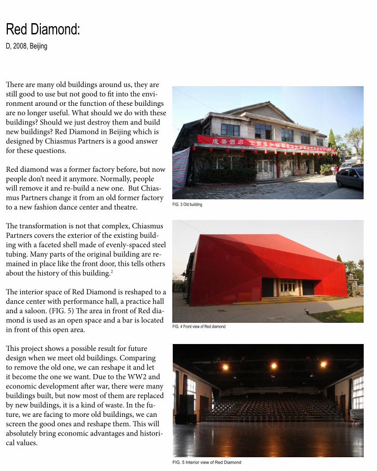
Red Diamond:D, 2008, Beijing
FIG. 3 Old building
FIG. 4 Front view of Red diamond
FIG. 5 Interior view of Red Diamond
There are many old buildings around us, they are still good to use but not good to fit into the envi-ronment around or the function of these buildings are no longer useful. What should we do with these buildings? Should we just destroy them and build new buildings? Red Diamond in Beijing which is designed by Chiasmus Partners is a good answer for these questions.
Red diamond was a former factory before, but now people don’t need it anymore. Normally, people will remove it and re-build a new one. But Chias-mus Partners change it from an old former factory to a new fashion dance center and theatre.
The transformation is not that complex, Chiasmus Partners covers the exterior of the existing build-ing with a faceted shell made of evenly-spaced steel tubing. Many parts of the original building are re-mained in place like the front door, this tells others about the history of this building.2
The interior space of Red Diamond is reshaped to a dance center with performance hall, a practice hall and a saloon. (FIG. 5) The area in front of Red dia-mond is used as an open space and a bar is located in front of this open area.
This project shows a possible result for future design when we meet old buildings. Comparing to remove the old one, we can reshape it and let it become the one we want. Due to the WW2 and economic development after war, there were many buildings built, but now most of them are replaced by new buildings, it is a kind of waste. In the fu-ture, we are facing to more old buildings, we can screen the good ones and reshape them. This will absolutely bring economic advantages and histori-cal values.


A.2Design Computation
Design computation is the most effective way to encourage design for all designers since 21th century. Why people would like to use computer? Issa (2010) says: “Computer, by their nature, are superb analytical engines. If correctly pro-grammed, they can follow a line of reasoning to its logical conclusion. They will never tired, never make silly arithmetical mistakes, and will gladly search through and correlate facts buried in the endless heaps of information they can store. They will do all that quickly and repeatedly, by follow-ing a set of instructions called a program, which tells them in minute detail how to manipulate the electrical impulses in their circuits. They can pres-ent the results of these manipulations in the form most suitable for human comprehension – even in dynamically changing images and sounds.”3 But the lack of computer is obvious, it is weak at cre-ative abilities and intuition. Therefore, it is a tool which is used to represent and liberate designers’ creative ability in an effective way.
However, the development of computation has three different phases. We are currently expe-riencing the third phase after “Folding” and “Non-Standard”. In this phase, it is “more easily accommodated the recognition of computational processes and the emerging technologies of ma-terialization.” (Oxman, Rivka and Robert Oxman 2014)
Furthermore, as the main part of design computa-tion and this semester’s study, parametric design should be described. It is emerged from late in post-Folding phase. It is a brand new form of
digital design thinking. Oxman and Rivka (2014) say: “parametric design thinking focuses upon a logic of associative and dependency relation-ship between objects and their parts-and- whole relationships.”4
In this part, I want to describe two precedents from two different aspects. Firstly, computer helps to break through the limitation vision like the form of building, many amazing buildings are designed. Secondly, computer is also smart at many aspects like physics acoustics and surround-ing environment. It helps designer to achieve their design target much easier.
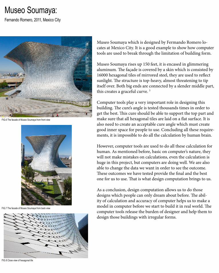
Museo Soumaya:Fernando Romero, 2011, Mexico City
Museo Soumaya which is designed by Fermando Romero lo-cates at Mexico City. It is a good example to show how computer tools are used to break through the limitation of building form.
Museo Soumaya rises up 150 feet, it is encased in glimmering aluminum. The façade is covered by a skin which is consisted by 16000 hexagonal tiles of mirrored steel, they are used to reflect sunlight. The structure is top-heavy, almost threatening to tip itself over. Both big ends are connected by a slender middle part, this creates a graceful curve. 5
Computer tools play a very important role in designing this building. The cure’s angle is tested thousands times in order to get the best. This cure should be able to support the top part and make sure that all hexagonal tiles are laid on a flat surface. It is also need to create an acceptable cure angle which must create good inner space for people to use. Concluding all these require-ments, it is impossible to do all the calculation by human brain.
However, computer tools are used to do all these calculation for human. As mentioned before, basic on computer’s nature, they will not make mistakes on calculations, even the calculation is huge in this project, but computers are doing well. We are also able to change the data we want in order to see the outcome. These outcomes we have tested provide the final and the best one for us to use. That is what design computation brings to us.
As a conclusion, design computation allows us to do those designs which people can only dream about before. The abil-ity of calculation and accuracy of computer helps us to make a model in computer before we start to build it in real world. The computer tools release the burden of designer and help them to design those buildings with irregular forms.
FIG.6 The facade of Museo Soumaya from front view
FIG.7 The facade of Museo Soumaya from back view
FIG.8 Close view of hexagonal tile
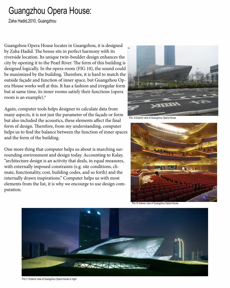
Guangzhou Opera House:Zaha Hadid,2010, Guangzhou
Guangzhou Opera House locates in Guangzhou, it is designed by Zaha Hadid. The house sits in perfect harmony with its riverside location. Its unique twin-boulder design enhances the city by opening it to the Pearl River. The form of this building is designed logically. In the opera room (FIG 10), the sound could be maximized by the building. Therefore, it is hard to match the outside façade and function of inner space, but Guangzhou Op-era House works well at this. It has a fashion and irregular form but at same time, its inner rooms satisfy their functions (opera room is an example).6
Again, computer tools helps designer to calculate data from many aspects, it is not just the parameter of the façade or form but also included the acoustics, these elements affect the final form of design. Therefore, from my understanding, computer helps us to find the balance between the function of inner spaces and the form of the building. One more thing that computer helps us about is marching sur-rounding environment and design today. Accounting to Kalay, “architecture design is an activity that deals, in equal measures, with externally imposed constraints (e.g. site conditions, cli-mate, functionality, cost, building codes, and so forth) and the internally drawn inspirations.” Computer helps us with most elements from the list, it is why we encourge to use design com-putation.
FIG. 9 Exterior view of Guangzhou Opera House
FIG.10 Interior view of Guangzhou Opera House
FIG.11 Exterior view of Guangzhou Opera House in night


A.3Composition/Generation
Currently, architecture is experiencing the shift from composition to generation. It leads a huge change of architectural process and brings both advantages and disadvantages to architecture. Before all, the definition of composition and generation are needed to describe. Composi-tion means the traditional way of architecture design, architects design their projects include thinking, modelling, sketching, manually. Gen-eration is a new way of design, it means the computational way of designing. The form of design is generated by a number of data, the outcomes will be created basic on these data and the designer choose the most appropriate one to use. Comparing these two deign methods, many differences are obvious. I would like to say, both methods have their own advantages and short-comings, so it is hard to say which one is better, but tend to generation is unstoppable, so I would like to have a brief and critical discussion about generation.
The concepts about “computerization” and “computation” are needed to explain. “Most
architects now use computers, but usually to simply digitize existing procedures with entities or processes that are preconceived in the mind of design” this mode is named computeriza-tion.7 However, computation is different. Sean Ahlquist and Achim Menges say: “computation is the processing of information and interactions between elements which constitute a specific en-vironment; it provides a framework for negotiat-ing the influencing, with the capacity to generate complex, order, form and structure.” Whatever, the generation here is more about computation.8
No one has question that generation brings huge benefits to design, but we all still in the develop-ment period of design computation, therefore the immature points are obvious, too. I will discuss two projects in this week to show some shortcomings in computational design.
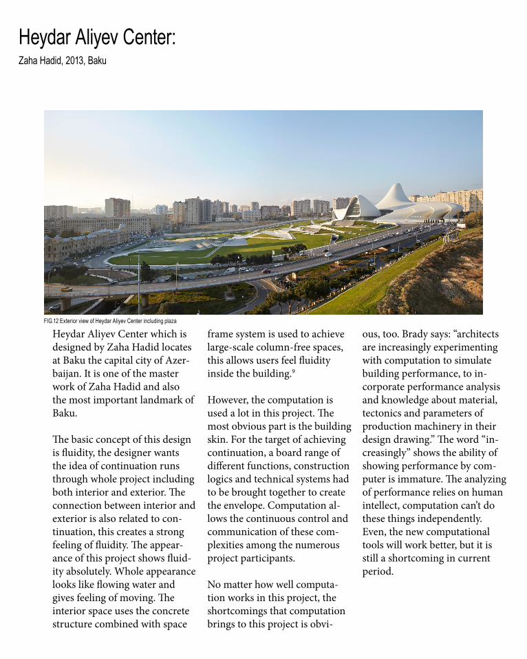
Heydar Aliyev Center:Zaha Hadid, 2013, Baku
Heydar Aliyev Center which is designed by Zaha Hadid locates at Baku the capital city of Azer-baijan. It is one of the master work of Zaha Hadid and also the most important landmark of Baku.
The basic concept of this design is fluidity, the designer wants the idea of continuation runs through whole project including both interior and exterior. The connection between interior and exterior is also related to con-tinuation, this creates a strong feeling of fluidity. The appear-ance of this project shows fluid-ity absolutely. Whole appearance looks like flowing water and gives feeling of moving. The interior space uses the concrete structure combined with space
frame system is used to achieve large-scale column-free spaces, this allows users feel fluidity inside the building.9
However, the computation is used a lot in this project. The most obvious part is the building skin. For the target of achieving continuation, a board range of different functions, construction logics and technical systems had to be brought together to create the envelope. Computation al-lows the continuous control and communication of these com-plexities among the numerous project participants.
No matter how well computa-tion works in this project, the shortcomings that computation brings to this project is obvi-
ous, too. Brady says: “architects are increasingly experimenting with computation to simulate building performance, to in-corporate performance analysis and knowledge about material, tectonics and parameters of production machinery in their design drawing.” The word “in-creasingly” shows the ability of showing performance by com-puter is immature. The analyzing of performance relies on human intellect, computation can’t do these things independently. Even, the new computational tools will work better, but it is still a shortcoming in current period.
FIG.12 Exterior view of Heydar Aliyev Center including plaza

Furthermore, the computation tool works weak to analysis surrounding environment from large scale, it is also weak to combine design target and traditional culture. From the picture (FIG.14), a feeling of unhar-monious comes to me. Even the designer works well on fit this building to surround-ing environment by creating the plaza, but if we look from a bigger scale, this building is strange, it looks like a UFO stands on rye. Another problem of combination of local culture is obvious, too. Because com-putation has no appreciation of beauty and understanding of local culture, all it does is following the logic of design tool, therefore the outcome might be strange. So, it always need human intellect to make some changes in order to let people feeling acceptable.
FIG.13 Exterior view of Heydar Aliyev Center
FIG.14 Exterior view of project from city scale
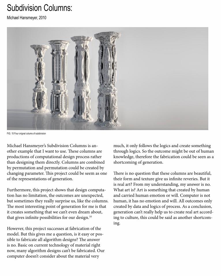
Subdivision Columns:Michael Hansmeyer, 2010
Michael Hansmeyer’s Subdivision Columns is an-other example that I want to use. These columns are productions of computational design process rather than designing them directly. Columns are combined by permutation and permutation could be created by changing parameter. This project could be seem as one of the representations of generation.
Furthermore, this project shows that design computa-tion has no limitation, the outcomes are unexpected, but sometimes they really surprise us, like the columns. The most interesting point of generation for me is that it creates something that we can’t even dream about, that gives infinite possibilities for our design.10
However, this project successes at fabrication of the model. But this gives me a question, is it easy or pos-sible to fabricate all algorithm designs? The answer is no. Basic on current technology of material right now, many algorithm designs can’t be fabricated. Our computer doesn’t consider about the material very
much, it only follows the logics and create something through logics. So the outcome might be out of human knowledge, therefore the fabrication could be seen as a shortcoming of generation.
There is no question that these columns are beautiful, their form and texture give us infinite reveries. But it is real art? From my understanding, my answer is no. What art is? Art is something that created by human and carried human emotion or will. Computer is not human, it has no emotion and will. All outcomes only created by data and logics of process. As a conclusion, generation can’t really help us to create real art accord-ing to culture, this could be said as another shortcom-ing.
FIG. 15 Four orignal colums of subdivision
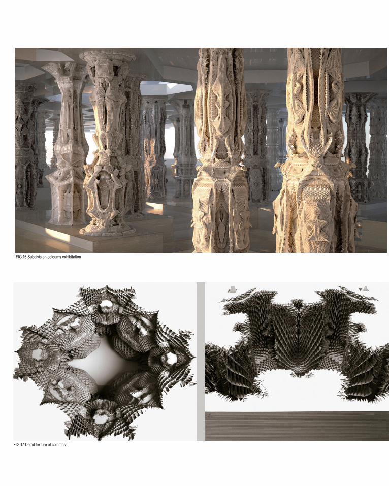
FIG.16 Subdivision coloums exhibitation
FIG.17 Detail texture of columns

A.4Conclusion
As a conclusion of Part A. There are mainly three parts are discussed: design futuring, design computation and composition/generation.
In the part of design futuring, two possible future designs are discussed. One of them is the design about sustainability. We all know that sustainability will be the main concept the in future, BanQ restaurant helps us have a brief understanding of one aspect of sustainability. The Red Diamond shows us another kind of future design, it shows how we reshape the old building to a new one. It gives us an economic way of design which is very useful.
In the part of design computation, two projects are described to show how computation assists us at many ways. Museo Soumaya shows that computer can help us with the complex calculations and simulation. Guangzhou Opera House shows that computation could not only help us at appearance but also interior design, like acoustics.
In the part of compotation/generation, two projects are selected to show what the shortcomings of genera-tion. Heydar Aliyev Center shows that computation is not that strong at working on building performance. It is also weak at combining design and surrounding environment from large scale. Subdivision Columns shows that computation works follow by computa-tional logics, it has no idea about human culture and emotion, therefore, the outcomes can’t be called as “real art”

A.5Learning outcome
Before I started this subject, even I already designed many times at computer, I thought that is computation, but after I have the understanding of computation, I find that the designs I learnt before can only be called “com-puterization”. However, the algorithmic thinking I learnt in last few weeks reshapes my understanding and my process of design. But, computation is not 100%, if we know the shortcomings of it, we might can do something to overcome them, this is what I get from the topic Com-position/Generation. We are going to future, therefore the understanding of tends of future design is another point that I get from learning of these weeks.

A.6Appendix- Algorithmic Sketches
I would like to choose this example is because, it is the box form of a Mobius circle. It shows that same geom-etry can be reformed to many different shapes in order to get unexpected outcomes.

Similar to last example, this time I reform the Mobius circle to straight line form and once again create box to the divided points. It shows that similar method could get different outcomes if the basic geometries are different.

Reference1, Fry, Tony (2008). Design Futuring: Sustainability, Ethics and New Practice (Oxford: Berg), pp. 1–16
2, Dezeen Magazine, “Red Diamond by Chiasmus Partners” ,2009 < http://www.dezeen.com/2009/10/26/red-diamond-by-chiasmus-partners/>
3, Issa, Rajaa ‘Essential Mathematics for Computational Design’, Second Edition, Robert McNeel and associates, pp 1
4, Oxman, Rivka and Robert Oxman, eds (2014). Theories of the Digital in Architecture (London; New York: Routledge), pp. 3
5, Dezeen Magazine, “Museo soumaya by Free fernando romero enterprise”, 2011 < http://www.dezeen.com/2011/04/28/museo-soumaya-by-free-fernando-romero-enterprise/>
6,Dezeen Magazine, “Guangzhou Opera House by Zaha Hadid Architects”, 2011 < http://www.dezeen.com/2011/02/25/guangzhou-opera-house-by-zaha-hadid-architects/>
7, Peters, Brady. (2013) ‘Computation Works: The Building of Algorithmic Thought’, Architectural Design, 83, 2, pp. 08-15
8, Sean Ahlquist and Achim Menges, Computation Design Thinking, John Wieley & Sons (Chichester), 2011
9, Archdaily, “Heydar Aliyev Center / Zaha Hadid Architects”, 2013 < http://www.archdaily.com/448774/heydar-aliyev-center-zaha-hadid-architects>
10, Hansmeyer Michael. “Subdivided Columns - A New Order”, 2010 < http://www.michael-hansmeyer.com/projects/columns_info.html>

Image Reference1-2 , John Horner, 2009, “BanQ / Office dA”, Photograph, viewed 01/08/2015, < http://www.archdaily.com/42581/banq-office-da>
3-5, Jenny Hung, 2009, “Red Diamond by Chiasmus Partners”, Photograph, viewed 01/08/2015, < http://www.dezeen.com/2009/10/26/red-diamond-by-chiasmus-partners/>
6-8, Unknown, 2011, “Museo soumaya by Free fernando romero enterprise”, Photograph, viewed 07/08/2015, < http://www.dezeen.com/2011/04/28/museo-soumaya-by-free-fernando-romero-enterprise/>
9-11, Unnknown, 2011, “Guangzhou Opera House by Zaha Hadid Architects”, Photograph, viewed 07/08/2015, < http://www.dezeen.com/2011/02/25/guangzhou-opera-house-by-zaha-hadid-architects/>
12-14, Hufton and Crow, 2013, “Heydar Aliyev Center / Zaha Hadid Architects”, Photograph, viewed 13/08/2015, < http://www.archdaily.com/448774/heydar-aliyev-center-zaha-hadid-architects>
15-17, Hansmeyer Michael, 2010, “Subdivided Columns - A New Order”, Photograph, viewed 13/08/2015, < http://www.michael-hansmeyer.com/projects/columns_info.html>

B.1. Research Field

Research Field Strip and Folding
There many different options for research field on LMS, I found strip and folding is the most imteresting one, From my perspective, strip and folding means folding a long , narrow structure using creative approach, including agnostic, non-linear and bottom up. Of course, one thing also interests me is the strips could loft to surfaces, a folding surface can be good to develop. By using strip and folding technique, the structure is fluid and dynamic, which varies constantly.
I choose to create and transform Biothing Pavillion ( one project of strip and folding ) using strip and folding techinique in Grasshopper. As a result, I get better understanding of computational design, which can also help me create my own project. Overall, this project is used as the starting point of developing my computational design skill.
As a designer, there are many things need to be considered, every little point that we consider might influence the whole structure of the design. How to let the building satisfy every exsting and potential users should be the biggest challenge for designers. Exterior desing is important, because it is the most showy part of a design, it plays an important role to attract users. However, even parametric design aims more about the exterior part, but it is also important to add practicability to the design. The design should consider the practicability part when they design a project, what they want to bring to users should be clearly considered. My object for this part is to integrate both practicbility and parateric design together, it will give the users all they want to obtain from this area.

Seroussi Pavilion Biothing Pairs 2007
The Seroussi Pavlilion is a good example of Stirp and Folding. Narrow plastic strips expand to different direction which looks like a mollusc swaying its feeler.
The Seroussi Pavilion’s structure is described as grown from self- modifing patterns of vectors based on magnetic Field. Magnetic field not only shape the form, but also create infinite variations and unexpect outcomes. The initial computations were done in plan then lifted via micoarching sections through frequencies of the sine function. Combing magnetic and sine function, it makes this project unique.
Serroussi Pavilion shows a different approach for creating forms using Strip and Fording technique, which provides me insights of computation design and new opportunities to develop my own design.


Selection Criteria
Acousic EffectThe biggest characteristic for parametric design is the appearcance. So the first selection criteria should be the acousic effect. It should be able to be accepted by users. Basic on the difference of user group, the type of design which could be accepted is different. In this case, the main users of a office should be young and mid age group, so the selected design could be able to satisfy their aesthetic
Constructivity
The selected iterations should be able to satisfy the principle of constructivity. It should be able to meet the basic definitions of physics. Grasshoppers sometims create inconceivable outcomes, they are beautiful but can not be built, because the outcome itself can not meet constructivity.
Material Performance
The selected iterations should be able to satisfy the material performance. I am doing strip and folding, it involves many folding surfaces or strips, so only appropriate material can help me achieve the effect I want
Light & Shadow Effect
As a ceiling, the ability to control light & shadow is important. The selected iterations should be good at doing this. which helps users to contain good experience.

B.2. Case Study 1.0
Seroussi Pavilion

SPECIES
Iterations
Division number of curveVariable = number slider ( Factor F)
F=1
F=2
F=3
F=10
Radius of center circleVariable = number slider ( Factor R)
R=0.01
R=1.08
R=2.52
R=10
Iterations
Division of center circleVariable = number slider ( Factor N)
N=1
N=10
N=35
N=75
Size of each simpleVariable = number slider ( Factor N)
N=10
N=35
N=150
N=500
SPECIES
Iterations
Division number/range of stripVariable = number slider ( Factor N)
N=1 for range
N=1 for divison
N=2 for range
N=2 for divison
N=5 for range
N=50 for divison
N=50 for range
N=5 for divison
length of stripsVariable = number slider ( Factor L)
L=-50
L=-24.5
L= 8.2
L= 36.6

Iterations
Curve pattern of strips Basic shape
B.3. Case Study 2.0
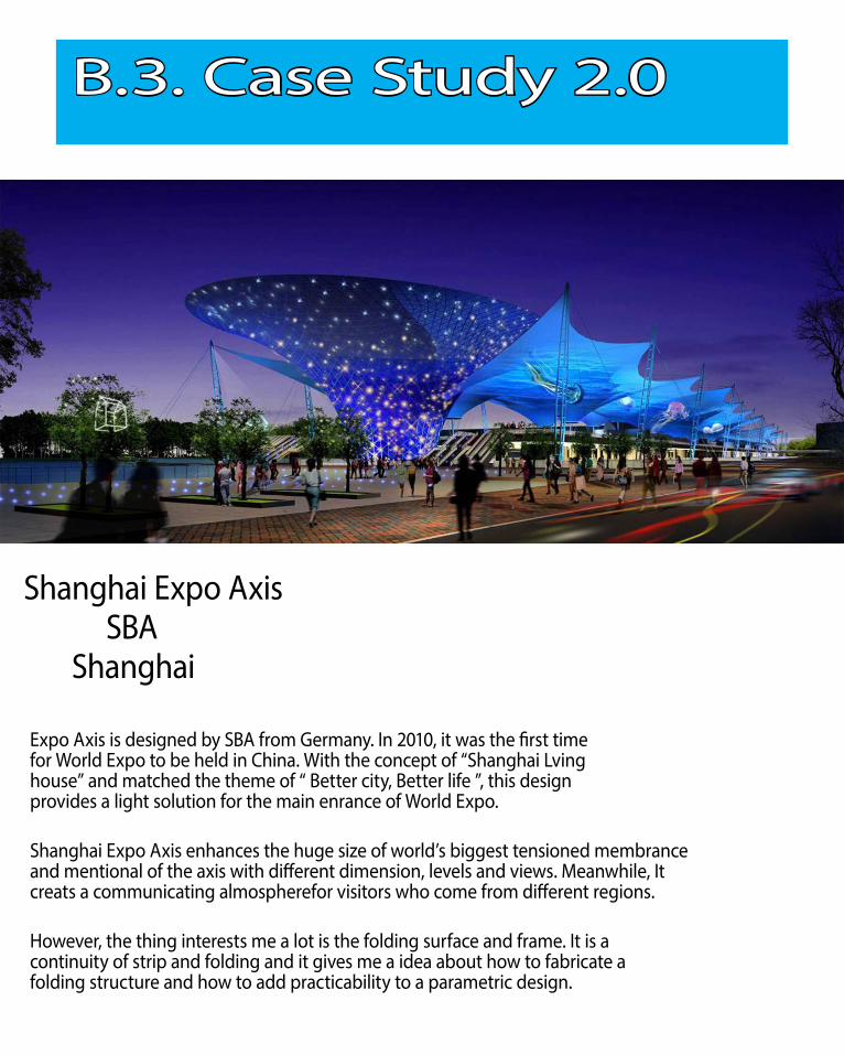
Shanghai Expo Axis SBA Shanghai
Expo Axis is designed by SBA from Germany. In 2010, it was the first time for World Expo to be held in China. With the concept of “Shanghai Lving house” and matched the theme of “ Better city, Better life ”, this design provides a light solution for the main enrance of World Expo.
Shanghai Expo Axis enhances the huge size of world’s biggest tensioned membrance and mentional of the axis with different dimension, levels and views. Meanwhile, It creats a communicating almospherefor visitors who come from different regions.
However, the thing interests me a lot is the folding surface and frame. It is a continuity of strip and folding and it gives me a idea about how to fabricate a folding structure and how to add practicability to a parametric design.

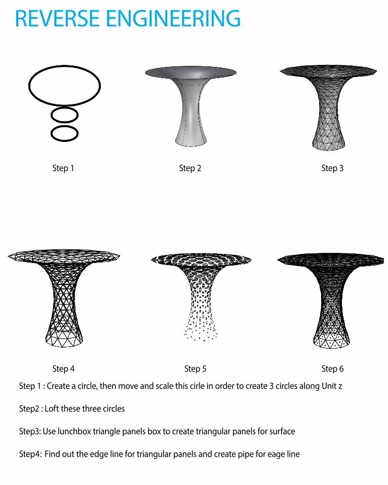
REVERSE ENGINEERING
Step 1 Step 2 Step 3
Step 4 Step 5 Step 6
Step 1 : Create a circle, then move and scale this cirle in order to create 3 circles along Unit z
Step2 : Loft these three circles
Step3: Use lunchbox triangle panels box to create triangular panels for surface
Step4:Find out the edge line for triangular panels and create pipe for eage line

Step 5 : Find out the triangles in triangular panels, then gradually varied the size of these tragnles by using attracting point.
Step 6 : Combine both pipe and triangles together.

B.4. Technique: Development
SPECIESIterations
Hight of basis supportVariable = number slider ( Factor H)
H=0 H=3.316
Radiu of basis circleVariable = number slider ( Factor R)
R=0.683 R=2.366
Height of the rised up mid circleVariable = number slider ( Factor H)
H=-10 H=--3

B.4. Technique: Development
H=6.176 H=12.256 H=18.941
R=5.466 R=9.543 R=10
H=0 H=20 H=50
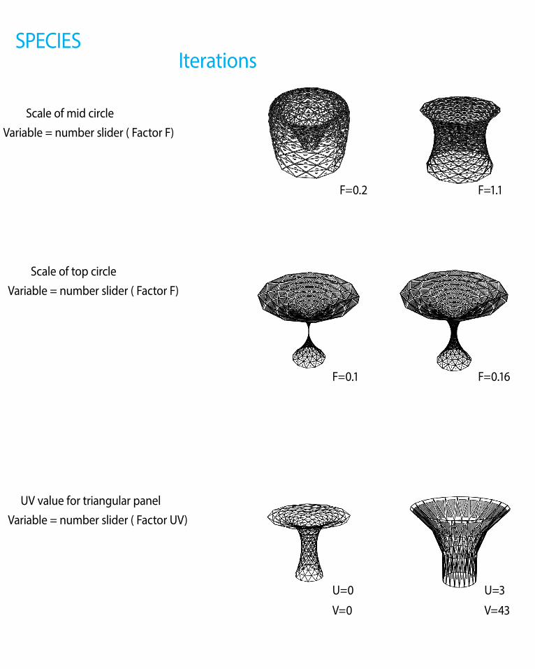
Scale of mid circleVariable = number slider ( Factor F)
SPECIESIterations
F=0.2 F=1.1
Scale of top circleVariable = number slider ( Factor F)
F=0.1 F=0.16
UV value for triangular panelVariable = number slider ( Factor UV)
U=0
V=0
U=3
V=43

F=5.3 F=7.3 F=10
F=0.52 F=1.11 F=2.46
U=5
V=14
U=21
V=9
U=21
V=43
SPECIESIterations
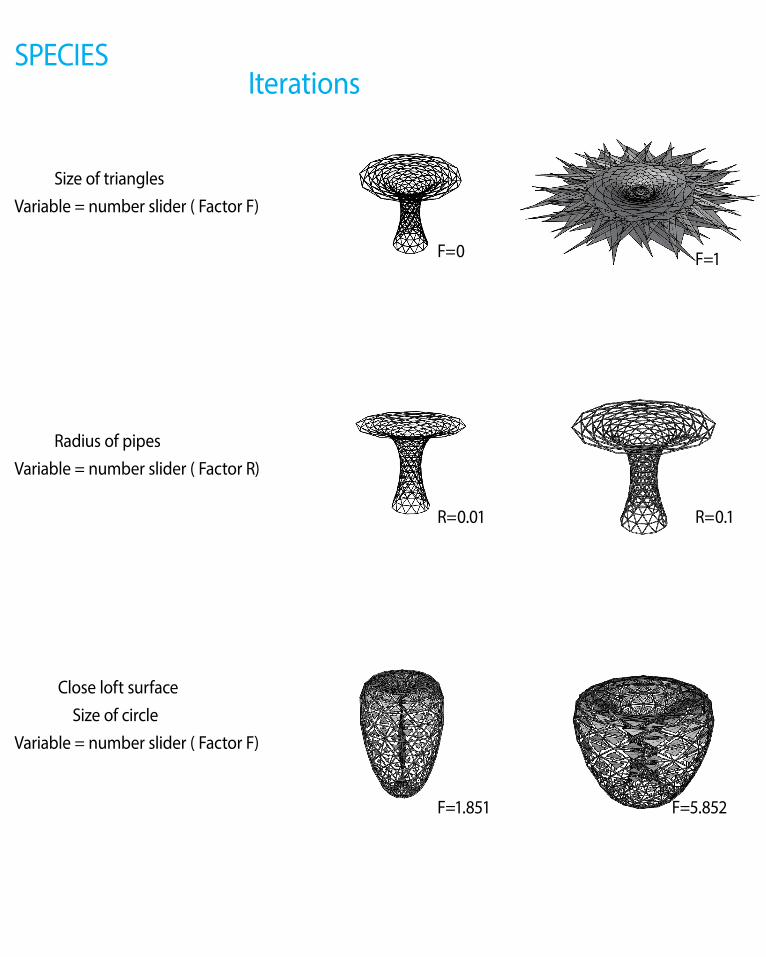
Size of trianglesVariable = number slider ( Factor F)
F=0 F=1
Radius of pipesVariable = number slider ( Factor R)
R=0.01 R=0.1
Close loft surface Size of circleVariable = number slider ( Factor F)
F=1.851 F=5.852

F=4 F=12 F=100
R=0.24 R=0.46 R=1
F=10 F=0 F=-1
SPECIESIterations
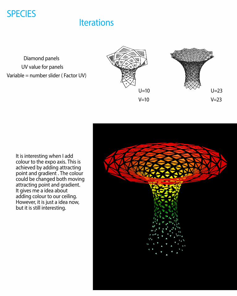
Diamond panels UV value for panelsVariable = number slider ( Factor UV)
U=10
V=10
U=23
V=23
It is interesting when I add colour to the expo axis. This is achieved by adding attracting point and gradient . The colour could be changed both moving attracting point and gradient. It gives me a idea about adding colour to our ceiling. However, it is just a idea now, but it is still interesting.

U=7
V=7
U=23
V=23
D=10
U=23
V=23
D=-10

B.5. Technique: Prototypes

The test of center joint is the starting point of my prototype. The center joint should satisfy two requirement. It should be sustainable to support the structure and the strips which connect to it. It also should be able to satisfy the design ideas. For examlple, the light and shadow effect. However, as the beginning, I tried different types of connection joints, in order to show how strips can connect to joint.

The second prototype I tested is Aperture. It is not designed by us. However, it is an good prototype in order to test how center joint could help human users o control the light. It could be decribled as a development from first prototype, which is quiet interesting.

Our group decide to loft those strips in order to get a surface which will allow as to add patterning definition. As shown before, the strips which created by magnetic field or other kinds of force always make the strips irregularly. Therefore, it is important to test the flexibility of the materials. The test we made above shows that it possible to create irregular surface, which supports our design concept. However, the rectangles on the surface is used to test that the surface still flexible when there has patterening on surface, which allows us to add patterening and control light/shadow in our design.

B.6. Technique: Proposal
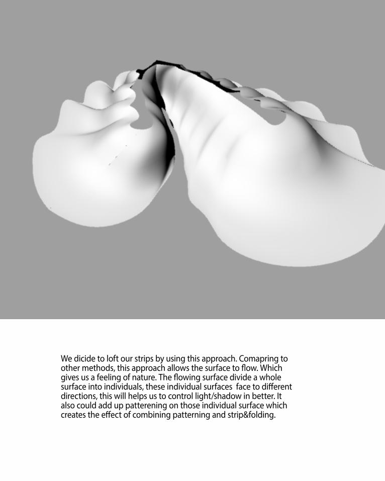
We dicide to loft our strips by using this approach. Comapring to other methods, this approach allows the surface to flow. Which gives us a feeling of nature. The flowing surface divide a whole surface into individuals, these individual surfaces face to different directions, this will helps us to control light/shadow in better. It also could add up patterening on those individual surface which creates the effect of combining patterning and strip&folding.

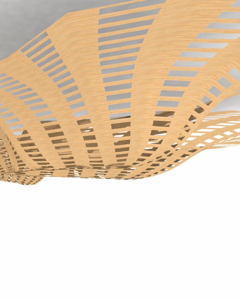
As mentioned before, light/shadow is one of the most important thing for desgining a ceilling. Our group’s idea is combining patterening and strips. Patterening is a good choice to control light. In our design, we use two different patterens, the one with big rectangle is used for the area/direction which needs more light, the one with small rectangle is used for area/direction which needs less light. The render effect with light shows the design achieves our goal.

One important thing need to mention about is the center joint. From prototype, we find out that center joint can not only be connection, it also can be light controller. The Aperture can be one way to achieve this. In future, the type of center joint could be developed further.
The last thing I want to talk is the basic form of our design. We choose to have 3 curves in total as the basic shape. These curves are facing to different directions and they have different form. This will help us better to manage our patterening on surfaces in order to control light/shadow.


B.7. Learning Objectives and Outcomes
The main objective for part B is making student understand what parametric desgin is and how it works. In part A, I analysized computational and parametric designs. These designs give me a brief idea about what are they, but they gives no idea about how the process of design works. However, as an continued process after part a, part b starts introduce the whole process of parametric design. Through the pratices of part b, I have a clear idea about how to do a parametric design.
There mainly two steps for the process of parametric design. Firstly, I need to find a direction on computer. The design idea could be started from very easy point, like what we do in case study 1. By setting the selection criterias, it is not hard to find out the useful iterations from the matrix. After that, we should keep developing the selected iterations until find out the best one. Secondly, I need to transfer a digital design to a real one. Parametric design is not like the normal design approach, the outcome from parametric could be very irrational, so it is my job to find out the best way to make my digital model to be made in real world.
As a conclusion, part b teaches me :1, the ability to revearse a design/thing back to computer. 2, the ability to make variations from original design. 3, the ability to set selection criterias in order to pick up the useful iterations. 4, the ability to transfer and develop the digital model to production in real world. 5, the ability to reform the production in order to make is satisfy the requirements from users. However, I am not good at these abilities right now. I believe during the process of part c, I will be better on doing a parametric design.
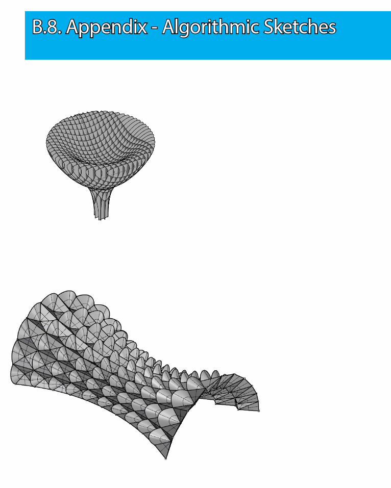
B.8. Appendix - Algorithmic Sketches

C.1 Design concept

C.1 Design concept

Finn: “ The prototypes that you fabricated were both well presented and compelling. Combining operability with material performance/patterning could yield a successful result. You should however set away from an approach which relies too heavily on man moving, mechanical pieces, as friction and fabrication tolerance make this sort of approach difficult to execute. The voussoir cloud-esque hanging ceiling installation seems to suggest an appropriate affect, however the loss of detail that is necessary to fabricated this design from timber strips in unfortunate. For part C focus on the material performance based operability of the system. Keep the mechanism simple and add interest by varying the performance along an element by adjusting the controlling pattern.”
The main problems for our design in part B are :
1, It relies too heavily on man moving, the prototype of the mechanical piece is not very successful. In our next stage, I will consider about how to control the multiple mechanical pieces by one device. It will allow the mechanical pieces to open and close in simple way rather than open or close them one after another by hand.
2, The details of fabrication are not shown roundly, some important details like the connection between strips and mechanical pieces, the connection between design and roof are missing. It leads some misundertandings about our project when people look at it. In next stage, I will consider more about the joints, it is also important in bringing parametric design to real life, without the joints, the design will not be able to build.
3, As a parametric design, our design could be more creative. I will look at new approaches of technique in order to bring better appearance.
4, The site should be considered more. I will find better forms of design to combine the site and our design together in better way. In the work of our part B, the site is considered but not enough yet. What we want to bring to our users should be the precondition before we design everything for this ceiling project.
5, The materials should be test in order to achieve the design goal. In our work in part B, we are lacking on testing the material which we can do better in my next stage.
C.1.1 Feedback of Pervious Work

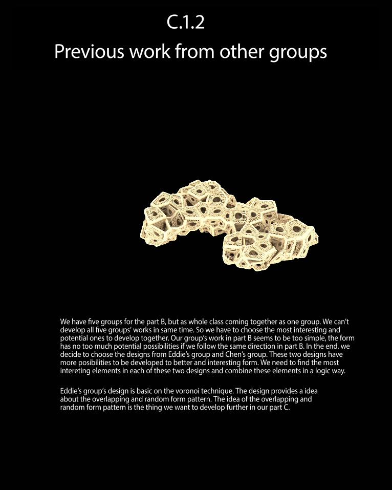
C.1.2 Previous work from other groups
We have five groups for the part B, but as whole class coming together as one group. We can’t develop all five groups’ works in same time. So we have to choose the most interesting and potential ones to develop together. Our group’s work in part B seems to be too simple, the form has no too much potential possibilities if we follow the same direction in part B. In the end, we decide to choose the designs from Eddie’s group and Chen’s group. These two designs have more posibilities to be developed to better and interesting form. We need to find the most intereting elements in each of these two designs and combine these elements in a logic way.
Eddie’s group’s design is basic on the voronoi technique. The design provides a idea about the overlapping and random form pattern. The idea of the overlapping and random form pattern is the thing we want to develop further in our part C.
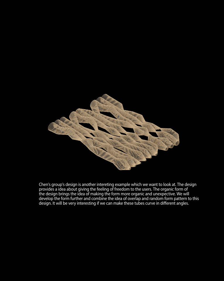
Chen’s group’s design is another intereting example which we want to look at. The design provides a idea about giving the feeling of freedom to the users. The organic form of the design brings the idea of making the form more organic and unexpective. We will develop the form further and combine the idea of overlap and random form pattern to this design. It will be very interesting if we can make these tubes curve in different angles.

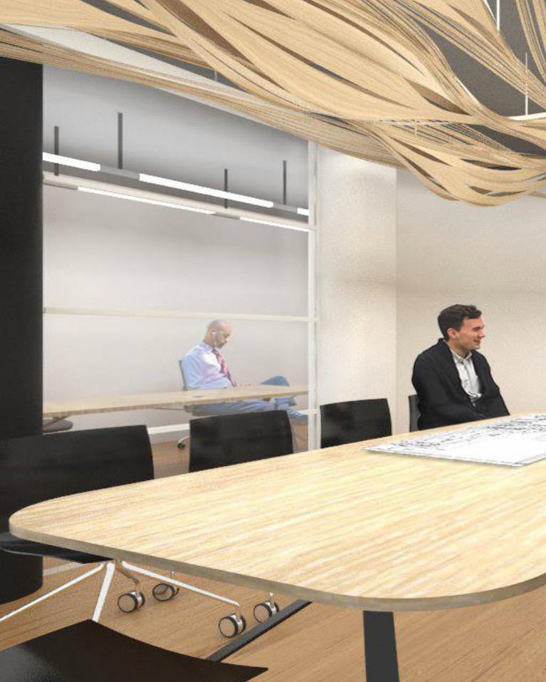
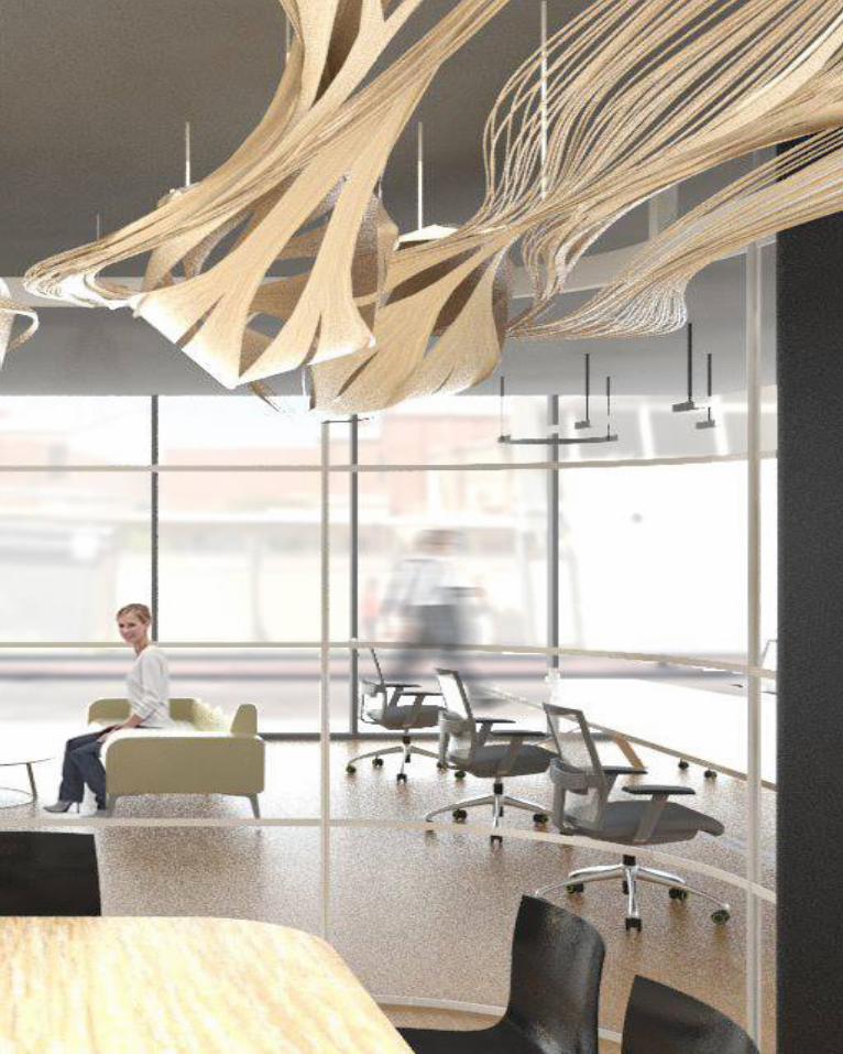
In part C, we are going to design a ceiling for one meeting room of Brunswick Office. The room locates at the middle area in a big offcial area, Three side walls are glass wall, the left one is concrete wall with a television. As a conference room, the main function is conference. The users will do the conference mainly in this room and maybe some daily works if they need a place.
After analyzing who will use this room and how they use it. It is important to anaysis what do users want to obtain from this area:
1, The users will want to work in a bright room when they have conference. It is necessary for us to bring enough light to the room.
2, The users want to have a dark room when they use television. So we have to consider block the light if it is necessary.
3, The room must provides a comforable feeling to the users. People might stay in this room for long time, if people can’t feel comforable in this area, it will be hard for them to stay inside for long time.
Overall Site Plan of the Floor
The Site Plan : Conference Room
C.1.3 Site Analysis - Brunswick Office

Light Requirement for the Room
The light requirement is the key issue which needs to be analysis carefully. The room is consisted by three glasswall, so the light accesses to room well through the glasswall. But When people sit around the table, the most important area we want to get brightness is the table, but people block the light from outside which comes through the glasswalls. Therefore, the key concept of the design is : let more light from the top of room arrive table. In this case, we can minimum the light source but get enough brightness. It will help to reduce the energy consumption.

FlOW
We start our design concept from FLOW. In order to bring a fluid structure, the idea of FLOW is what we want to start from. FLOW means moving or running smoothly with the unbroken continuity. The feeling of the continuity is what we want to create basic on our part B work. Most of my group mates do the STRIP & FOLDING as their case study, the contunity which shown by Seroussi Pavilion is the effect we want to achieve and develop.
C.1.4 Finalising Design Concept

C.1.4 Finalising Design Concept

C.1.4 Finalising Design Concept
BIOMIMICRY
As mentioned in last pages, the FLOW is the starting point of our design concept. In this step, we want to develop the idea of FLOW further. The natural flows seem to be the one of the most creative and amazing thing in the world. There are many great designs bring the natural things to architectural world. So we want bring the natural flows to our design as well. The successful examples bring the inspiration to us. Which we want to develop our form in more stochastic and unexpectable ways.


C.1.4 Finalising Design Concept
SYSTEMIC GROWTH
Here are some attempts which bring the unexpectable flow lines to the site. However, it is only a test to see the effect, but it provides some ideas about how to fit the room by using the flow.
We will develop further about the flow and we will add up our design concepts in order to make these lines more logic and useful, rather than just saying it is beautiful.

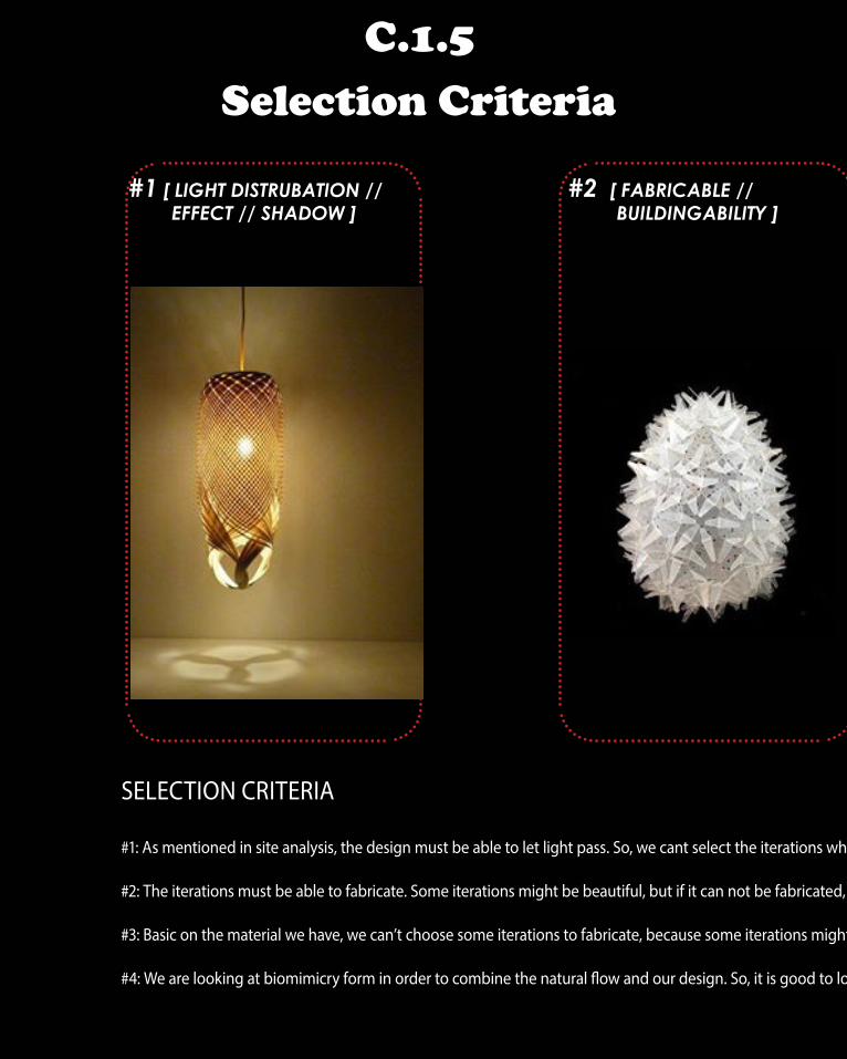
C.1.5 Selection Criteria
#1 [ LIGHT DISTRUBATION // EFFECT // SHADOW ]
#2 [ FABRICABLE // BUILDINGABILITY ]
SELECTION CRITERIA
#1: As mentioned in site analysis, the design must be able to let light pass. So, we cant select the iterations which block the light in large area.
#2: The iterations must be able to fabricate. Some iterations might be beautiful, but if it can not be fabricated, we will not develop it further. Because we need to bring the digital model to real world.
#3: Basic on the material we have, we can’t choose some iterations to fabricate, because some iterations might be bended by large curve. If we can’t find the material which allow to bend by large curve, we will fail to fabricate it.
#4: We are looking at biomimicry form in order to combine the natural flow and our design. So, it is good to look at the iterations which have better biomimicry morphology.

# 4 [ BIOMMICRY MORPHOLOGY // DESIGNWISE ]
#3 [ MATERIAL PERFORMANCE ]
SELECTION CRITERIA
#1: As mentioned in site analysis, the design must be able to let light pass. So, we cant select the iterations which block the light in large area.
#2: The iterations must be able to fabricate. Some iterations might be beautiful, but if it can not be fabricated, we will not develop it further. Because we need to bring the digital model to real world.
#3: Basic on the material we have, we can’t choose some iterations to fabricate, because some iterations might be bended by large curve. If we can’t find the material which allow to bend by large curve, we will fail to fabricate it.
#4: We are looking at biomimicry form in order to combine the natural flow and our design. So, it is good to look at the iterations which have better biomimicry morphology.
C.1.6 Form Finding - Matrix

C.1.6 Form Finding - Matrix

#01 #05
#02 #06
#03 #07
#04 #08

#09 #13
#10 #14
#11 #15
#12 #16
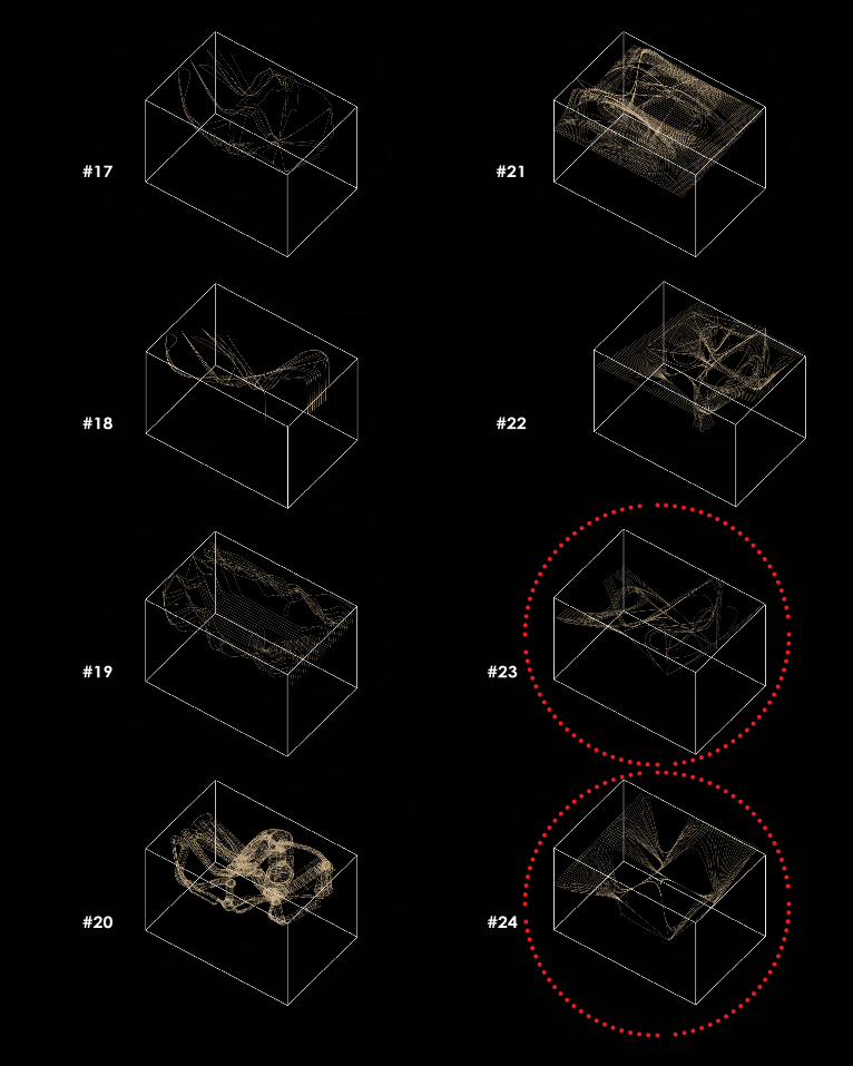
#17 #21
#18 #22
#19 #23
#20 #24

#25 #29
#26 #30
#27 #31
#28 #32

#33 #37
#34 #38
#34
#35 #39
#36 #40

#41
#42
#43
#44
C.1.7 Selected Iterations
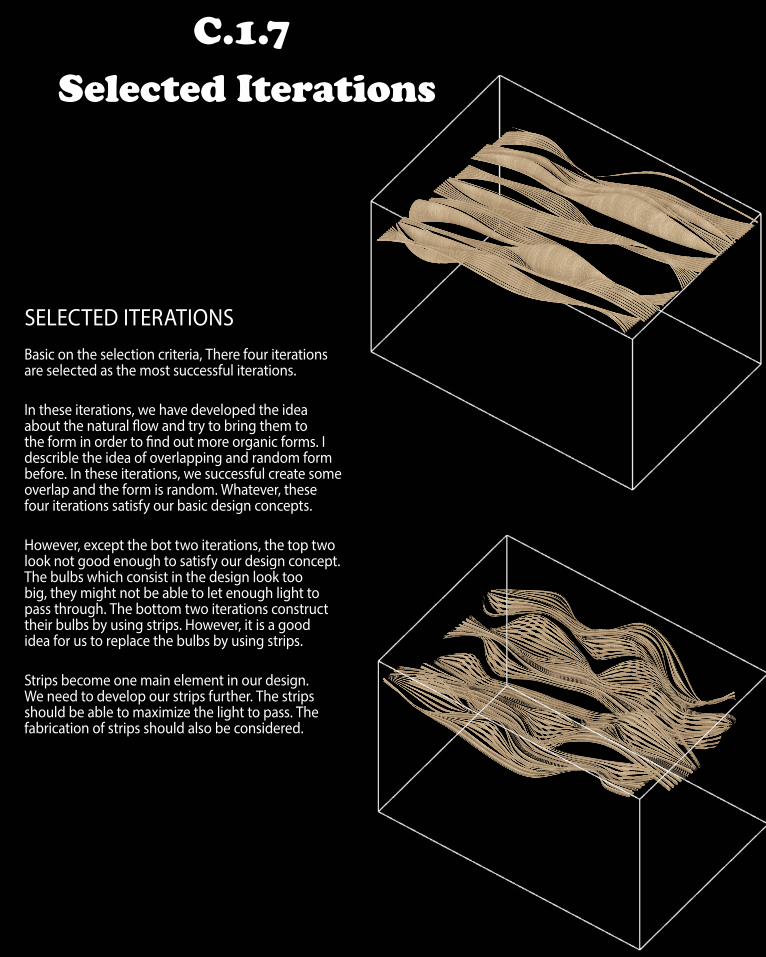
SELECTED ITERATIONSBasic on the selection criteria, There four iterations are selected as the most successful iterations.
In these iterations, we have developed the idea about the natural flow and try to bring them to the form in order to find out more organic forms. I describle the idea of overlapping and random form before. In these iterations, we successful create some overlap and the form is random. Whatever, these four iterations satisfy our basic design concepts.
However, except the bot two iterations, the top two look not good enough to satisfy our design concept. The bulbs which consist in the design look too big, they might not be able to let enough light to pass through. The bottom two iterations construct their bulbs by using strips. However, it is a good idea for us to replace the bulbs by using strips.
Strips become one main element in our design. We need to develop our strips further. The strips should be able to maximize the light to pass. The fabrication of strips should also be considered.


Option 1
C.1.8 Final Geometry Selection

Option 2
We picked four iterations as our selected iteration. However, we have to choose one as our final geometry, Comparing to the option 1, option 2 seems to be more organized, because of the restriction of fabrication, option 2 is more possible to be frabricated. Even option 1 looks better at appearance, but option 2 is the final decision for our final geometry selection.
However, there has one importat thing we need to change, the both ends of option 2 look like be cutting by the room. It breaks the cotinuity of whole structure. So we have to bring the dispersive ends to some points in order to save the integrality of the structure. It will also help the fabrication rather than the dispersive ends one.

C.1.8 Final Geometry


Environmental feedback within the design process creadit: Nick Dean
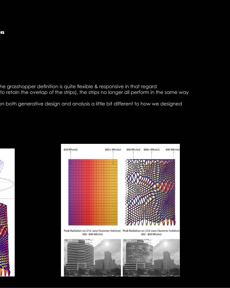
• Workflow that narrows the gap between 3d modeling and analysis• Creates a feedback loop that allows for iterations to occur with reference to real-world parameters (i.e. light exposure & distribution) instead of in isolation• Exploration into design potentials and performance at a very early stage within the design process
• More time to reach the optimum performance of the building/installation
Ladybug plug-in creadit: Nick Dean
• Whilst it is a plug-in that analyses sunlight exposure and distribution, there is quite a high level of control that allows the user to pinpoint exact locations for the sun
• these locations ‘acted’ as lights within the meeting room (4 different loca-tions/positions were input into the SUNPATH COMPONENT)
• RADIATION ANALYSIS component was used in order to analyse the distribu-tion of light within the meeting room
• Areas of most light exposure were located• A point was set at each of these areas• Points then used as ATTRACTOR POINTS in order to vary the thickness of the
strips throughout the geometry• Closest to attractor points = thinner stripsNote: Still had to retain the overlap of the strips in order for the rivet connec-tions to be possible
As mentioned before, the light and shadow effect is one of the most impor-tant element for designing a ceiling. From the selected iterations part, we find out that the bulbs might block most light. Therefore, in this stage, we are go-ing to transfer bulbs to strip covered bulbs. We are going to design the strips in order to bring more gaps for light passing
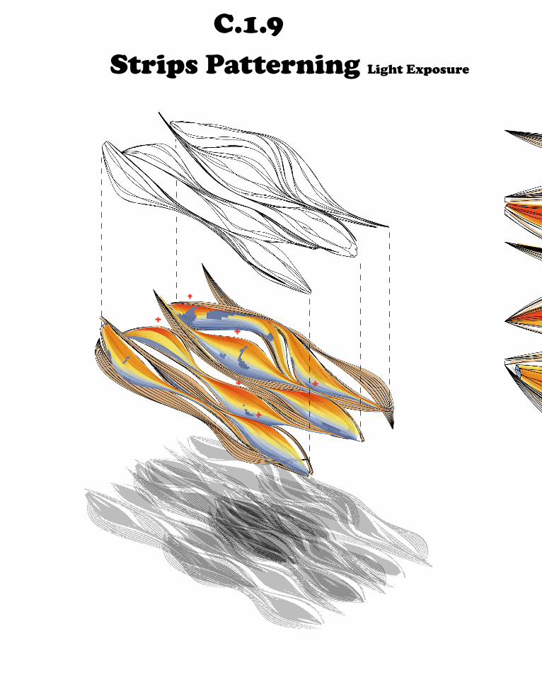
C.1.9 Strips Patterning Influencing Form & Pattern Distribution
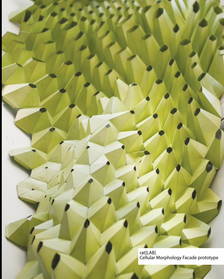
rat[LAB]Cellular Morphology Facade prototype
C.1.9 Strips Patterning Influencing Form & Pattern Distribution

C.1.9 Strips Patterning Influencing Form & Pattern Distribution
Contribution/relevance to the design creadit: Nick Dean
• Works towards creating context-dependent parameters• Design is somewhat unique to the meeting room site• Different ‘lighting plan/layout’ would contribute to different effects, therefore, the grasshopper definition is quite flexible & responsive in that regard• Although the effect is not overly noticeable due to fabrication restrictions (had to retain the overlap of the strips), the strips no longer all perform in the same way • strip thicknesses vary within each bulb• In a general sense, working with Ladybug establishes a workflow that draws upon both generative design and analysis a little bit different to how we designed
throughout the semester

C.1.9 Strips Patterning Establishing Light Points

C.1.9 Strips Patterning Establishing Light Points
C.1.9 Strips Patterning Light Exposure

With the hellp from ladybug plug-in, the light export status is shwon in dia-grams. As we can see, the bulbs are the main areas which receive more light. In another word, they block more lights. As mentioned before, our design concept is letting more light pass through our design, so it is not good enough for us if we keep our bulbs in solid. Therefore, the report from light exposure provides evidence for why we need to rebuild these bulbs into strip cover bulbs.
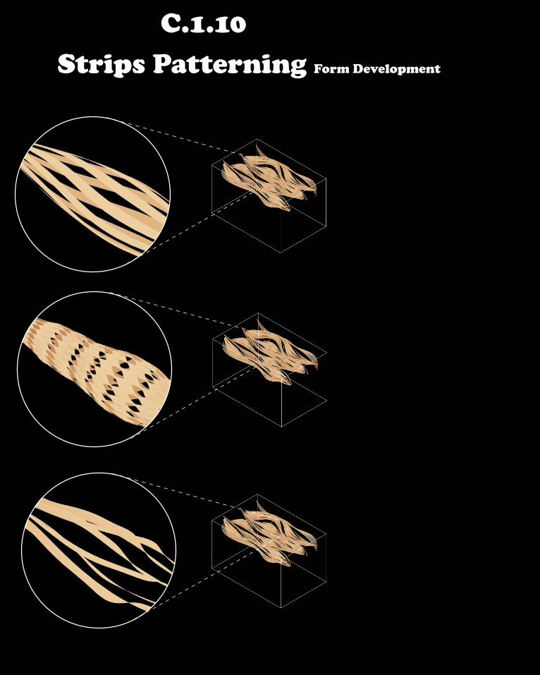
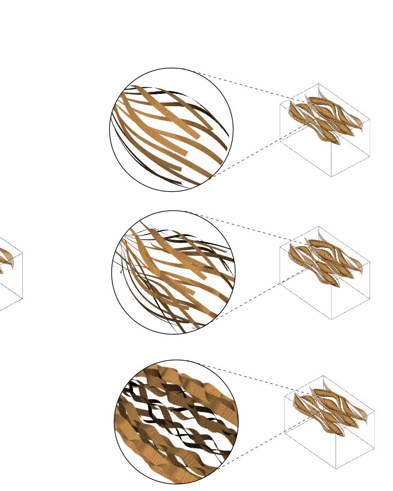
C.1.10 Strips Patterning Form Development


C.1.10 Strips Patterning Form Development
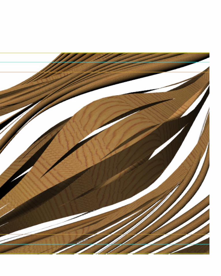
Here are many different variations for the form of strips, most of these varia-tions are beautiful and pratical. But relate to the fabrication, we have to let the strips overlap each other. So these beautiful strips will not be able to use on our design. We have to discover more approaches to create overlapping strips and good ability of light passing.
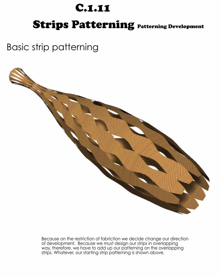
C.1.11 Strips Patterning Patterning Development
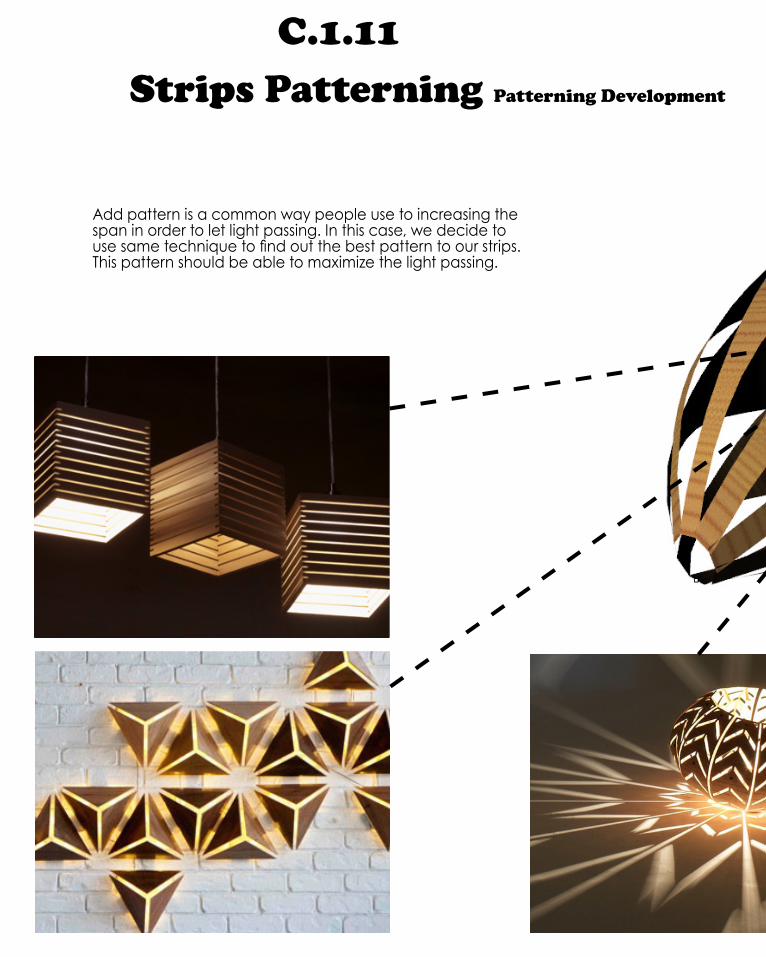
Basic strip patterning
Because on the restriction of fabriction we decide change our direction of development. Because we must design our strips in overlapping way, therefore, we have to add up our patterning on the overlapping strips. Whatever, our starting strip patterning is shown above.

Developed strip patterning
Before we add patterning on the strips. Our final strips is developed in order to increase the overlapping area. This helps us to have larger span area at the parts which strips away from each other. Furthermore, the overlapping strips create a larger touching area beween strips and the ribs inside.
C.1.11 Strips Patterning Patterning Development
Add pattern is a common way people use to increasing the span in order to let light passing. In this case, we decide to use same technique to find out the best pattern to our strips. This pattern should be able to maximize the light passing.


C.1.11 Strips Patterning Patterning Development
Option 1

Option 2

C.1.11 Strips Patterning Patterning Development
By testing light passing ability for each of these two options, option 2 seems to be better both at the apperance. But it still has some problems. The gap is still small comparing to the whole strips. Even it allows more light go through, but I think it is not good enough. As mention in light exposure part, the bulbs block most light, the bigger bulb is, the more light is blocked by it. Therefore, I suggest to have bigger span on bigger area of bulb. I mean, when the bulb is getting bigger in some areas, the gap should be better as well. Let the span area always 60% of the total area, this should be better to achieve the light requirement goal. Whatever, the group decide to use option2 as our final patterning.

Option 1
Option 2

C.1.12 Strips Patterning Final Pattern

C.1.13 Final Geometry With Patterning

C.1.13 Final Geometry With Patterning

C.2 Tectonic Element & Prototypes
C.2 Tectonic Element & Prototypes

B A S E G E O M E T R Y
S T R I P S A P P L I E D T O B R E P
W E A V I N G S T R I P S T O I N T E R S E C T
F I N D I N G T H E M I D P O I N T O F I N -T E R S E C T I O N S T O C R E A T E P O I N T S F O R F A B R I C A T I O N .
C.2.1 Strips Test - Prototype Modeling

C.2.1 Strips Test - Prototype Modeling

C.2.1 Strips Test - Prototype Modeling
I n i t i a l P r o t o t y p e : P o l y p r o p y l e m e | T a b s

C.2.1 Strips Test - Prototype Modeling P r o t o t y p e : T i m b e r V e n e e r L a m i n a t e B a c k | R i v e t s
P r e s s S t u d s R i v e t s
We start our prototype from a polypropyleme. At that time, we have not yet decide the final strip patterning, so we just use polypropyleme to make one bulb in order to show the effct. The effect is not bad, Whatever, in order to achieve your design concept, we have to use timber as the material for our design. We have the timber venner laminate back to make bulb. We use rivets and press studs as the connect method, it is very strong connection. But the shortcomings are clear, too. Some areas of the bulb are quiet narrow, these areas might not be able to give the screw hole. Furthermore, the connections change the integral flexibility of the material, the area around connection is more tough than other areas along materials.

C.2.2 Ribs Test - Interior structure
South Pond Pavilion, Chicago 2010 by Studio Gang Architects
1 2 3 4 5
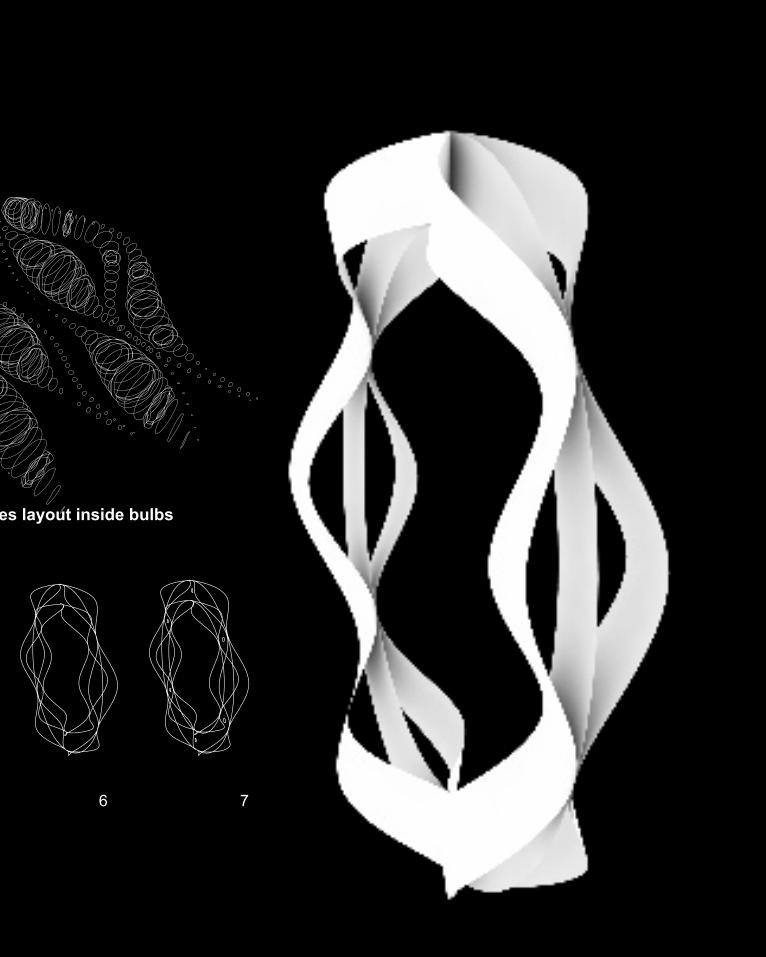
Circles layout inside bulbs
C.2.2 Ribs Test - Interior structure
6 7
Circles layout inside bulbs

C.2.2 Ribs Prototype Test - Interior structure
Paper rib prototype
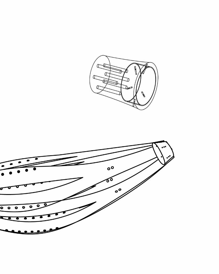
We start our rib which will be the interior structure inside the bulb. It is like the bone in human body, the main function for ribs is should be structure, the strips will connect to the ribs in order to stay at the position where we want them to stay. However, the bulbs have some very narrow areas, like the areas shown in picture at left hand side. We decide to design bulb only for those wide areas and use the technique of cane for the narrow part, which means bulbs for wide area and connect the end to cane in order to finish the long narrow part.
Back to the rib part, we design the rib in a complex way and it looks nice. We start our prototype by paper, the paper rib looks good which 100% represent our design idea about rib. But we need to use timber material for our deisgn, therefore we start to test the timber venner laminate back material which we used for our strips. It looks very flexiable in the strips test, but it disappoints us. It breaks at some areas, the timber venner laminate back material is not flexiable enough to satisfy our needs. Therefore, we have to test more materials to find out the suitable one.
Whatever, the test is expensive. The material costs us $300, but now it can’t be used anyway. I guess next time we have to buy small pieces to test rather than just believe one material and buy it without a reasonable test.

C.2.2 Ribs Prototype Test - Interior structure
Timber veneer laminate back rib prototype

C.2.3 Material Test - Selection of Material
TIMBER VENEER PAPER BACKTIMBER VENEER LAMINATE BACK
BREAKING POINT

C.2.3 Material Test - Selection of Material
TIMBER VENEER PAPER BACKTIMBER VENEER LAMINATE BACK
BREAKING POINT
Timber veneer laminate back Timber veneer paper back
As mentioned before, because our rib prototype breaks beause the flexibility of material. We decide to change another material for our design.
The compare is between timber venner laminate back and timber veneer paper back. Comparing to timber veneer liminate back material, timber venner paper back is more flexiable, it allow big-ger bend before break. The diagram at left hand side shows tim-ber venner paper back has smoother curve.
After analyzing the breaking point of each metrial, the colour of the materials is also important element to consider. The brighter colour of timber veneer paper back is not good at bring the natu-ral wood colour to the room which we are bit of disappointing, but the advantage of brighter colour brings the brighter feeling of the room, however, it is definitely what we want in our design, so timber venner paper back material is not 100% we want but it is still acceptable.
Comparing timber veneer laminate back, timber venner paper back is much cheaper, it is not only benefit for our prototype and fabrication, but also good to save cost if we want to build it in real world for a real design project. The cost is an important element for designer to consider when they design something.

C.2.4 Bulb Design - Connetion design
Pro to t y p e 1
Pro to t y p e 2

C.2.4 Bulb Design - Connetion design
FA B R I C AT I O N P R O C E S S DA MAG E
D I F F U S E D T E N S I L E P R E S S U R E

C.2.4 Bulb Design - Sewn Strip/Rib connection

C.2.4 Bulb Design - Sewn Strip/Rib connection
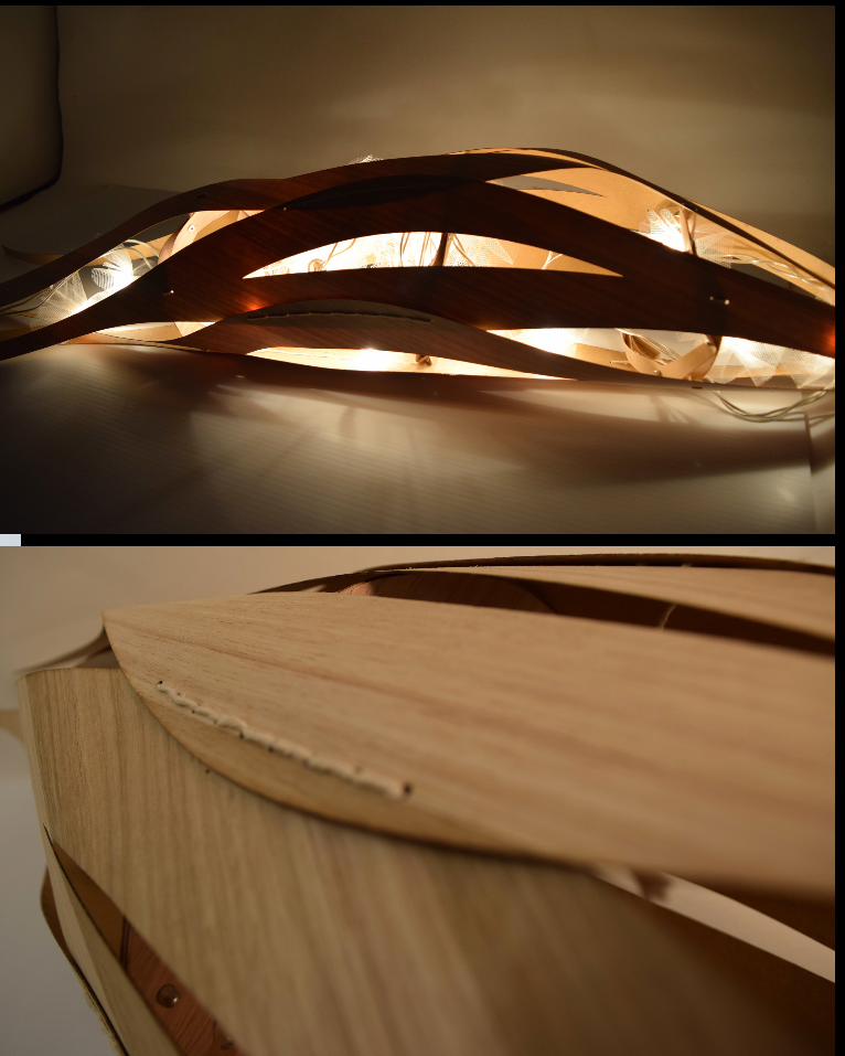
Sewn strip/rib connection is a very beatiful and effective way to connect strip to rib. Comparing to use rivet, it is more soft way in order to protect material and flexibility. The effect is good, it achieves most our requirements.
However, it is very time comsuming method. We only make two 1:3 model, but it take more than 20 hours to fabricate. I think it has better way to achieve same goal but much less time consuming. As a designer, it is important to have the ability to bring the digital model to reality. Whatever, this method is a very good attempt. But I guess somethings complex method doesn’t mean better effect. This could be a lesson for me.

C.2.4 Bulb Design - Strip/Rod connection
C.2.4 Bulb Design - Strip/Rod connection

C.2.4 Bulb Design - Febrication Process

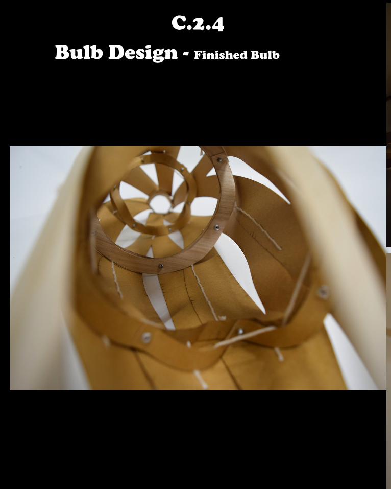
C.2.4 Bulb Design - Finished Bulb
C.2.4 Bulb Design - Finished Bulb
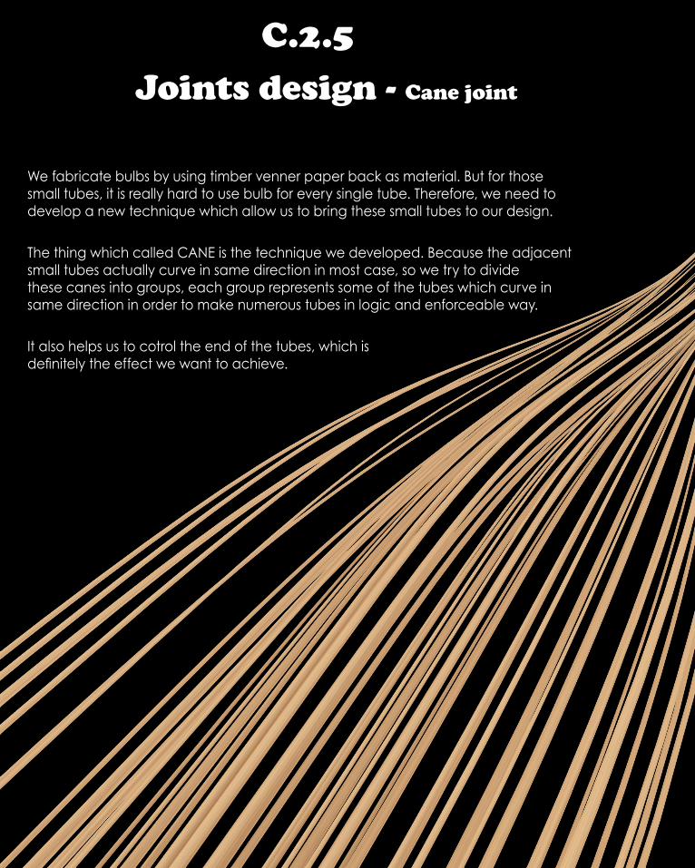
C.2.5 Joints design - Cane joint
We fabricate bulbs by using timber venner paper back as material. But for those small tubes, it is really hard to use bulb for every single tube. Therefore, we need to develop a new technique which allow us to bring these small tubes to our design.
The thing which called CANE is the technique we developed. Because the adjacent small tubes actually curve in same direction in most case, so we try to divide these canes into groups, each group represents some of the tubes which curve in same direction in order to make numerous tubes in logic and enforceable way.
It also helps us to cotrol the end of the tubes, which is definitely the effect we want to achieve.

C.2.5 Joints design - Cane joint

C.2.5 Joint Design - Cane joint
Material & Precedent

C.2.5 Joint Design - Cane joint
The Rise By Cita

C.2.5 Joint Design - Cane joint

C.2.5 Joint Design - Cane joint

C.2.5 Joint Design - Cane joint

C.2.5 Joint Design - Cane joint

C.2.5 Joint Design - Cane joint
C.2.5 Joint Design - Cane joint
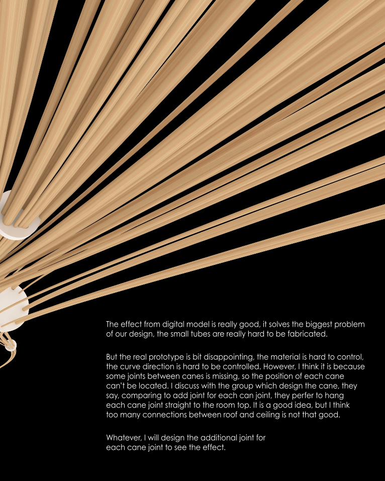
The effect from digital model is really good, it solves the biggest problem of our design, the small tubes are really hard to be fabricated.
But the real prototype is bit disappointing, the material is hard to control, the curve direction is hard to be controlled. However, I think it is because some joints between canes is missing, so the position of each cane can’t be located. I discuss with the group which design the cane, they say, comparing to add joint for each can joint, they perfer to hang each cane joint straight to the room top. It is a good idea, but I think too many connections between roof and ceiling is not that good.
Whatever, I will design the additional joint for each cane joint to see the effect.

C.2.5 Joint Design - Cane joint

C.2.5 Joint Design - Cane joint

C.2.6 Joint Design - Joint between elements
Initially, we decide to have many intersections between ribs and canes, in order to create good overlap appearance and natural/stochastic flows. Therefore, it becomes very important to add up joints for each intersections, in order to bring a effective and strong connection to connect the elements together.
There are two types of elements we have for our design - Cane and Rib. Therefore, it brings three potential intersections : 1, the intersection between two ribs. (rib to rib) 2, the intersection between two canes. (cane to cane) 3, the intersection between rib and cane. (rib to cane) Basic on these three potential intersection types, my job is designing the joint in order to satisfy the goal of connection.
Joints between elements is restricted by many factors which means I cant decide which material I am going to use and which overall form I am going to design. I must follow others work in order to keep minimulm number of joints.
Whatever, even the joint design for my part has many restriction, but it is still the part which I am interesting. Unlike the core element like bulb and cane which is important and visible. Joint are normally tiny and invisiable, but it proves the sense of connecting different part together, in order to achieve the final design goal. Without the joint, the design will be different fragments.Furthermore, unlike the core elements, joints is normally designed at late stages, in our case, I designed my joints after my group decide to use the rib as the skelcton for bulb and cane joint for cane, because when they decide these core element, all designs which I designed beforehand can not be used, because they are not relevant to these two core elements. However, I like the desgin things under restrictions, it helps me to aim my goal straight way.

C.2.6 Joint Design - Joint between elements
Rib to Rib
Cane to Cane
Rib to Cane

C.2.6 Joint Design - Rib to Rib
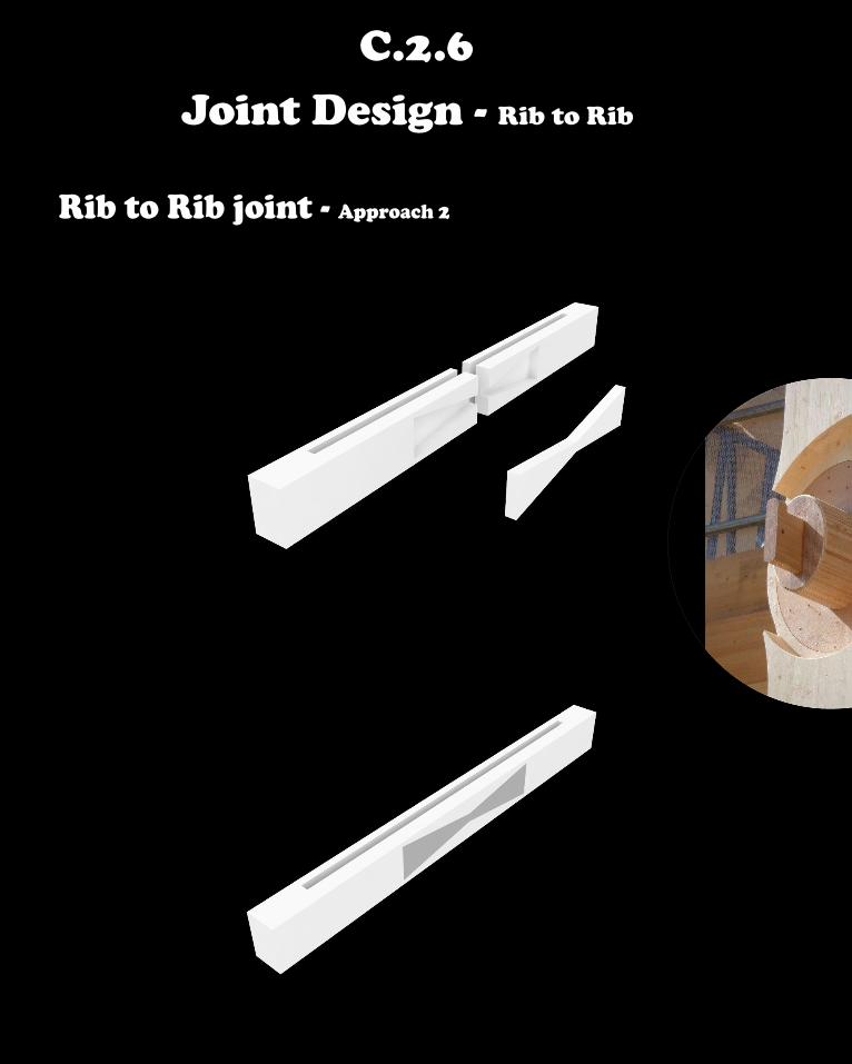
Rib to Rib joint - Approach 1
C.2.6 Joint Design - Rib to Rib
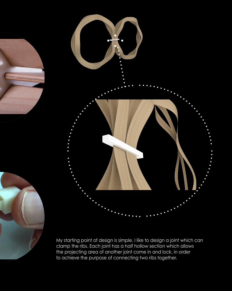
My starting point of design is simple. I like to design a joint which can clamp the ribs. Each joint has a half hollow section which allows the projecting area of another joint come in and lock, in order to achieve the purpose of connecting two ribs together.
C.2.6 Joint Design - Rib to Rib
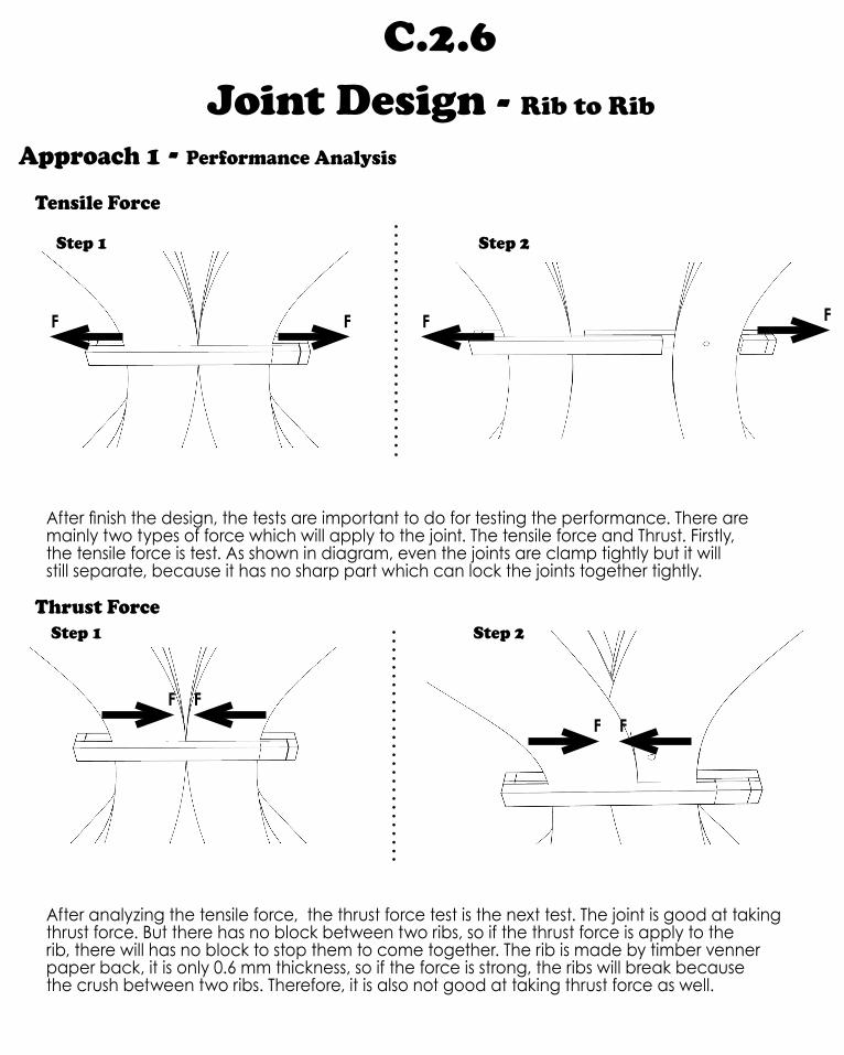
Approach 1 - Performance Analysis
Tensile Force
F F F F
After finish the design, the tests are important to do for testing the performance. There are mainly two types of force which will apply to the joint. The tensile force and Thrust. Firstly, the tensile force is test. As shown in diagram, even the joints are clamp tightly but it will still separate, because it has no sharp part which can lock the joints together tightly.
Step 1 Step 2
Thrust Force
FFFF
After analyzing the tensile force, the thrust force test is the next test. The joint is good at taking thrust force. But there has no block between two ribs, so if the thrust force is apply to the rib, there will has no block to stop them to come together. The rib is made by timber venner paper back, it is only 0.6 mm thickness, so if the force is strong, the ribs will break because the crush between two ribs. Therefore, it is also not good at taking thrust force as well.
Step 1 Step 2

F
3D print Prototype
When I fabricate the joint, I find an technical problem, which 3D printer will print a thickness for the surface which is not set thickness. So when I print out the prototype, the hollow section can be inserted, because printer set a thickness with 0.3 mm for the four side surface of hollow section.
For solving this problem, the only method is increase the hight and weight of the hollow section and leave enough area for insertion.But it will create a result that the hollow section (Short side of the joint) is higher and fater than solid area (long side).
Therefore, for maintaining the intergrality of the joint. This approach is given up.
One more question about this prototype is colour. For keeping the same with my groupmates’ 3D print, I use white material for my first prototype, but I find it is better to use yellow colour. In order to hide our joint when we use timer as our material for the design. So, I will try to use yellow for my other joints.
C.2.6 3D Printer Study

C.2.6 3D Printer Study
ABS Plastic Filament - Colour Selection
As mentioned, the colour of ABS plastic filament is needed to select. There are mainly seven colours of ABS plastic filament. White is normally we use, but the material we use for our design is timber. White colour is conspicuous. So I think yellow is better colour to use.
C.2.6 Joint Design - Rib to Rib
Rib to Rib joint - Approach 2

C.2.6 Joint Design - Rib to Rib
In my previous design, the two problems of design are discovered through the test. In order to solve the problem, I designed my second design. It is used to overcome the tensile force. I designed a sharp rabbet at the front side, in order to achieve the goal of againsting tensile force.
C.2.6 Joint Design - Rib to Rib
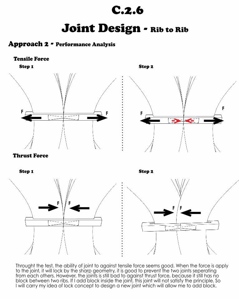
Approach 2 - Performance Analysis
Tensile Force
F F FF
Step 1 Step 2
Thrust Force
F F
Step 1 Step 2
Throught the test, the ability of joint to against tensile force seems good. When the force is apply to the joint, it will lock by the sharp geometry, it is good to prevent the two joints seperating from each others. However, the joints is still bad to against thrust force, because it still has no block between two ribs. If I add block inside the joint, this joint will not satisfy the principle. So I will carry my idea of lock concept to design a new joint which will allow me to add block.
F F
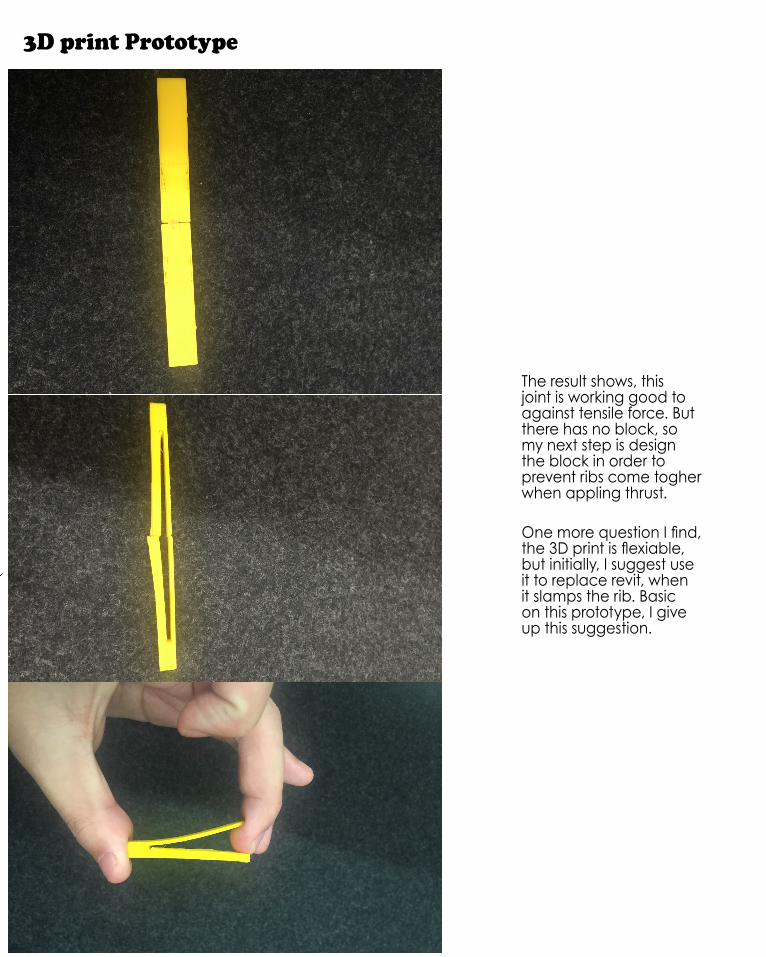
3D print Prototype
The result shows, this joint is working good to against tensile force. But there has no block, so my next step is design the block in order to prevent ribs come togher when appling thrust.
One more question I find, the 3D print is flexiable, but initially, I suggest use it to replace revit, when it slamps the rib. Basic on this prototype, I give up this suggestion.
C.2.6 Joint Design - Rib to Rib
Rib to Rib joint - Approach 3
C.2.6 Joint Design - Rib to Rib
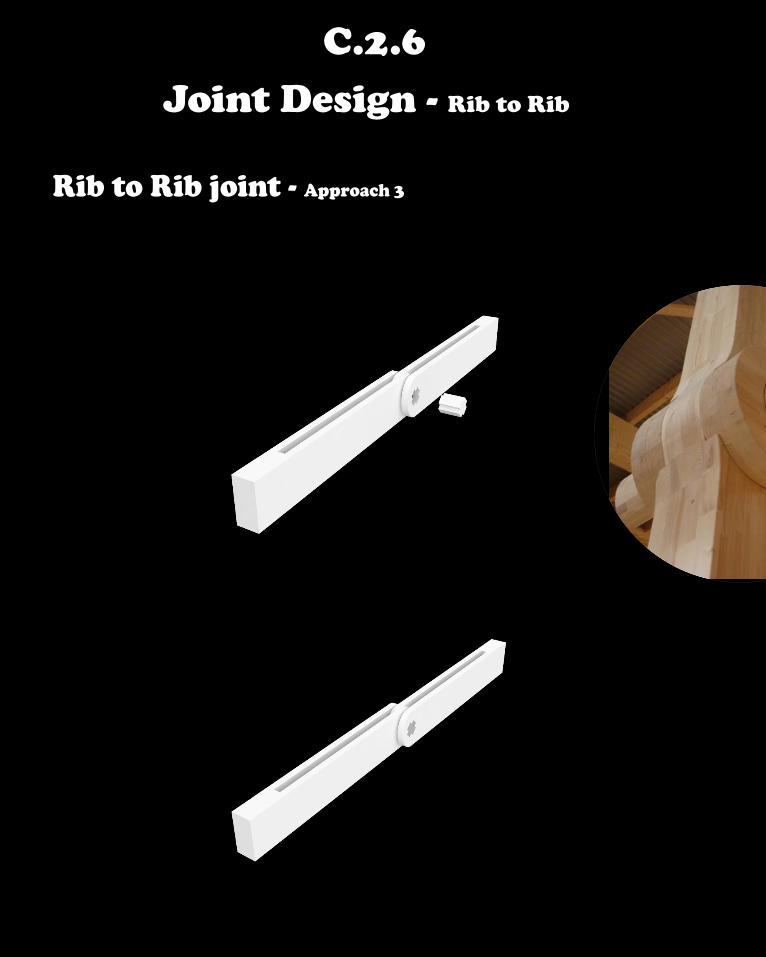
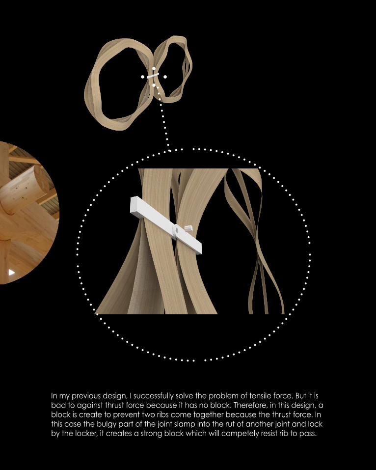
In my previous design, I successfully solve the problem of tensile force. But it is bad to against thrust force because it has no block. Therefore, in this design, a block is create to prevent two ribs come together because the thrust force. In this case the bulgy part of the joint slamp into the rut of another joint and lock by the locker, it creates a strong block which will competely resist rib to pass.
C.2.6 Joint Design - Rib to Rib
Approach 3 - Performance Analysis
Tensile Force
F F F F
Step 1 Step 2
Thrust Force
Step 1 Step 2
F FF F
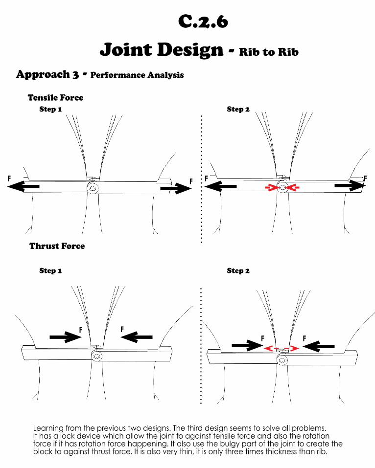
Learning from the previous two designs. The third design seems to solve all problems. It has a lock device which allow the joint to against tensile force and also the rotation force if it has rotation force happening. It also use the bulgy part of the joint to create the block to against thrust force. It is also very thin, it is only three times thickness than rib.
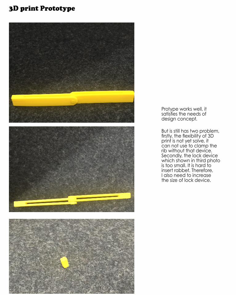
3D print Prototype
Protype works well, it satisfies the needs of design concept.
But is still has two problem, firstly, the flexibility of 3D print is not yet solve, it can not use to clamp the rib without that device. Secondly, the lock device which shown in third photo is too small. It is hard to insert rabbet. Therefore, I also need to increase the size of lock device.

C.2.6 Joint Design - Rib to Rib
Approach 3 - Development
The approach 3 seems good in digital model, but when 3D print them, I find they are not as strong as I imaging. The two strip sides are flexiable, that is definitely not what I want. Initally, I want use the joint to replace the rivet at the intersection, because I think the joint will clamp joint tighly. But the outcome is disappointing. Therefore, I have to develop my joint one more step in order to let it satisfing the design concept. The joint method is fine, so I only need to consider about how to let the joint clamping rib tightly. Fortunately, I could just use the rivet to fix the joint straight to rib. It will 100% fix two elements together tightly.
But because we can’t control the rivet’s size, because it is factory-making. The size of screw hole is 1.05cm, but in my design, my joint is only 1cm hight. So I need to increase the hight of the joint. Fortunately, in the purpose to reduce the size of joint, the previous joint is small, so it is totally okay to crease the hight, the best hight from my test is 15 cm. I will add the screw hold up to the 15cm hight new joint. Furthermore, I think the lock device for previous design is small, it is not good enough to against the force when the force is huge. It also very hard to put the small lock device into the rabbt. So it is important for to increase the size of lock device, too.
One more thing which need to be mentioned is after I have the prototype, I find I can reduce the length of the joint in order to minimum the size of joint.
Previous design
Developed design

C.2.6 Joint Design - Rib to Rib
Final Joint - Rib to Rib

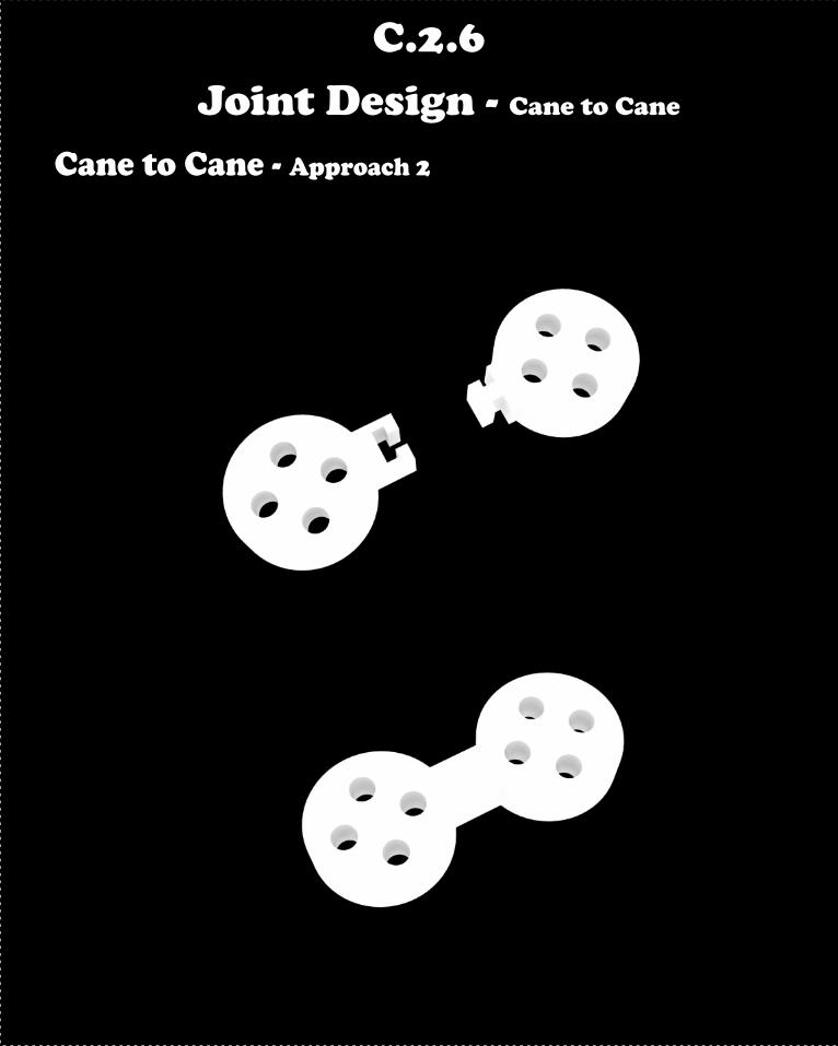
C.2.6 Joint Design - Cane to Cane
Cane to Cane - Approach 1

C.2.6 Joint Design - Cane to Cane
For the Cane to Cane joint, I want to add my joint to the cane joint which design by my classmates. For the purpose of reducing joint, I design the addtion part to the cane joint in order to connect different cane groups together to create form.
I start my design from a simple design. It is consisted by two parts. An cyclinder area and a shell area, the principle is simple, put the cyclinder to the shell part and the shell part will lock them together. It needs a good thickness in order to lock them together (if the cane joint is too thin, the touching area will be small, it might not good enough to lock. Therefore, before my classmates decide the thickness, I would like to make the prototype with thickness 1cm.

C.2.6 Joint Design - Cane to Cane
Approach 1 - Performance Analysis
F
F
Rotation Force
F
F
Step 1
Step 2
Weakest Part
A
There are mainly two disadvantages of this design. Firstly, because it has the cylinder part, so it can not be fix in shell 100%, the smooth curve surface bring a slight movement when the force apply to the joint. Secondly, because we want to assemable two joints together, so it needs a thin area at the start of the cylinder in order to lock. (As shown in right diagrams) So the thin area of the joint might be the weakest part of the joint, it may break in the futher. So the design can not satisfy all the needs from the test result.

C.2.6 Joint Design - Cane to Cane
3D print Prototype
The prototype is fine, but the lack of design still need to develop.
However, I study a little about the size of joint connection. The first photo’s joint has smaller size and it can not connect as well as the big one which shown in second photo. Therefore, the size of joint connection is important thing to consider.
C.2.6 Joint Design - Cane to Cane
Cane to Cane - Approach 2
C.2.6 Joint Design - Cane to Cane
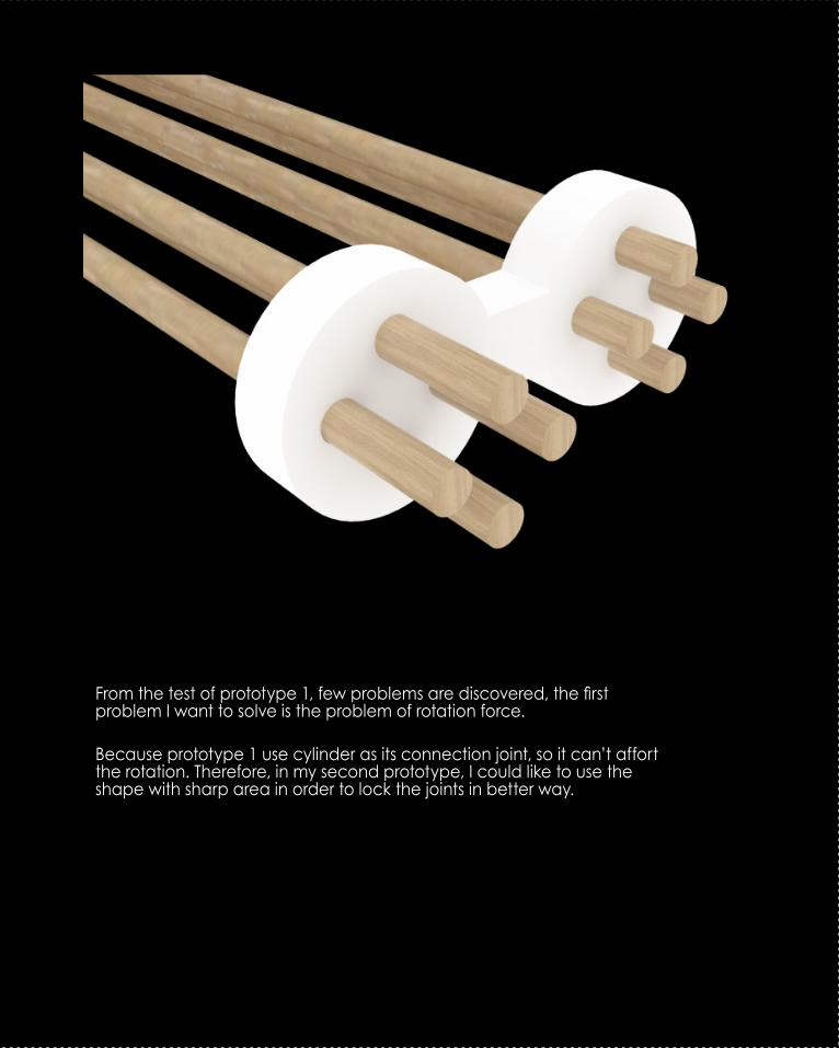
From the test of prototype 1, few problems are discovered, the first problem I want to solve is the problem of rotation force.
Because prototype 1 use cylinder as its connection joint, so it can’t affort the rotation. Therefore, in my second prototype, I could like to use the shape with sharp area in order to lock the joints in better way.

C.2.6 Joint Design - Cane to Cane
Approach 2 - Performance Analysis
Rotation Force
Step 1
Step 2
F
F
F
F
This design is mainly used to solve the problem of rotation. By swaping a sharp geometry, the joint is good to against the rotation force right now. But the second problem is not yet be solved. Even when two joint come together, the connection part will be an cube. But they are not real integrity, when a huge tensile force apply to the joint, the thin part will definitely break at first.
So it is important bring more smooth shape rather than a H shape which is too sharp.
Weakest Part

3D print Prototype
The prototype is fine, but the lack of design still need to develop. I still print two different sizes joint connection, once again, the bigger one have better performance.
C.2.6 Joint Design - Cane to Cane
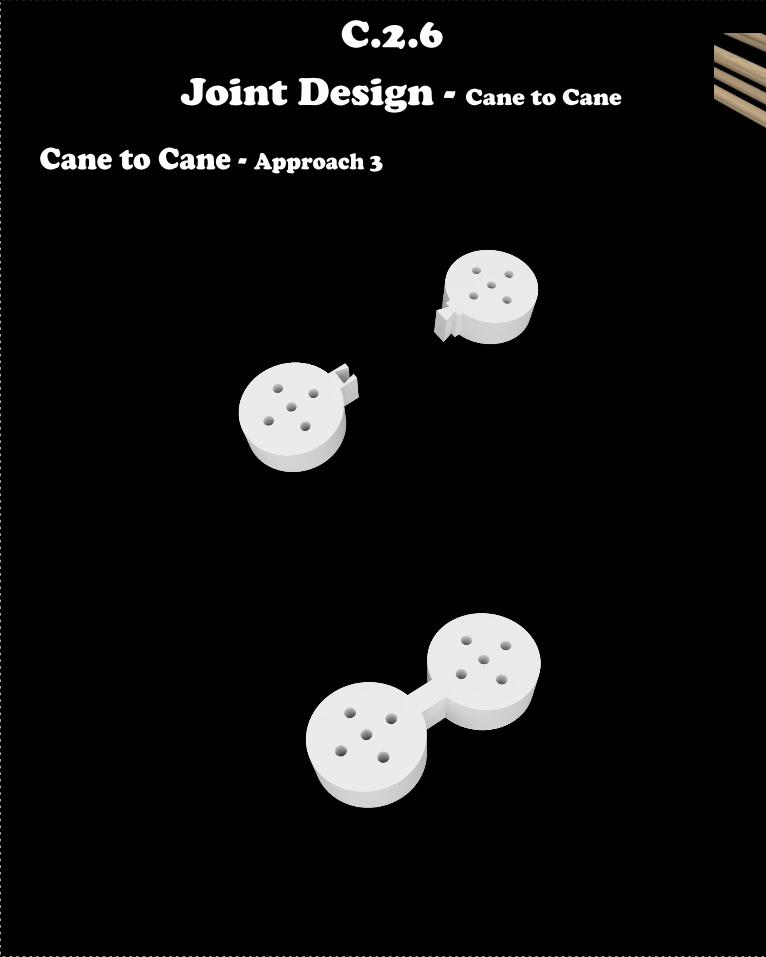
Cane to Cane - Approach 3

C.2.6 Joint Design - Cane to Cane
This time, my design is aiming to solve the second problem which reduce the thin area and bring a smooth geometry for the connection area.
Trapezoid is selected to be used. There are many good example from real live, which trapezoid is used as the connection at tables.
Whatever, it seems good to overcome all problems I have at current stage. I would like to do the test to see the outcome.
C.2.6 Joint Design - Cane to Cane
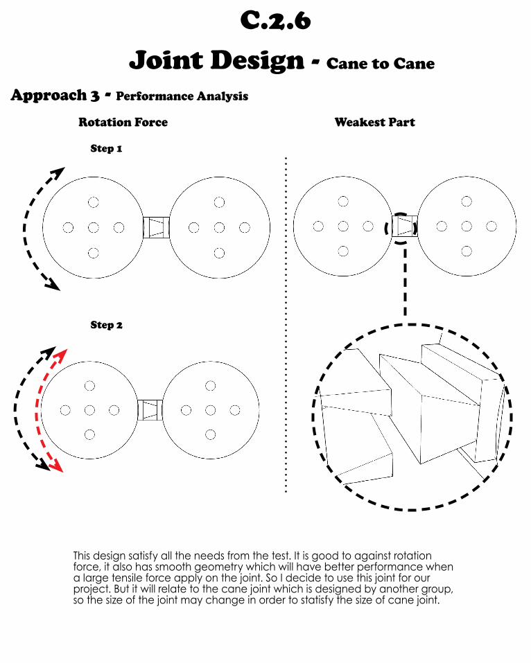
Approach 3 - Performance Analysis
Rotation Force
Step 1
Step 2
Weakest Part
This design satisfy all the needs from the test. It is good to against rotation force, it also has smooth geometry which will have better performance when a large tensile force apply on the joint. So I decide to use this joint for our project. But it will relate to the cane joint which is designed by another group, so the size of the joint may change in order to statisfy the size of cane joint.
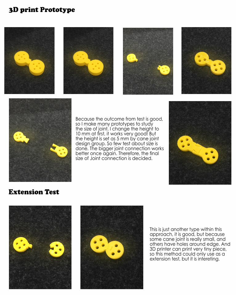
3D print Prototype
Because the outcome from test is good, so I make many prototypes to study the size of joint. I change the height to 10 mm at first, it works very good! But the height is set as 5 mm by cane joint design group. So few test about size is done. The bigger joint connection works better once again. Therefore, the final size of Joint connection is decided.
Extension Test
This is just another type within this approach, it is good, but because some cane joint is really small, and others have holes around edge. And 3D printer can print very tiny piece, so this method could only use as a extension test, but it is intereting.
C.2.6 Joint Design - Cane to Cane
Approach 3 - Development
Prototype
Real cane joint
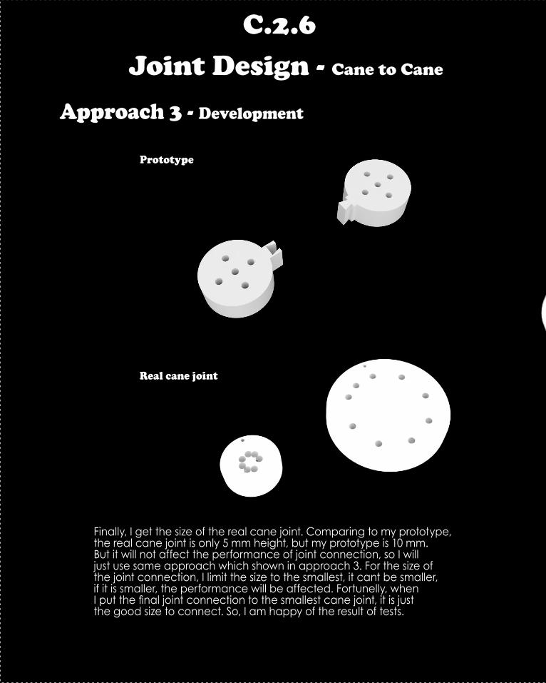
Finally, I get the size of the real cane joint. Comparing to my prototype, the real cane joint is only 5 mm height, but my prototype is 10 mm. But it will not affect the performance of joint connection, so I will just use same approach which shown in approach 3. For the size of the joint connection, I limit the size to the smallest, it cant be smaller, if it is smaller, the performance will be affected. Fortunelly, when I put the final joint connection to the smallest cane joint, it is just the good size to connect. So, I am happy of the result of tests.

C.2.6 Joint Design - Cane to Cane
Final joint - Cane to Cane

C.2.6 Joint Design - Cane to Rib
Finally, the joint between cane and rib is needed to design. But through the tests in designing joint between rib to rib and cane to cane. The best approach is already be found. So just combine them together to get the result is logic and effective. The joint shown above is the combination result. It looks good and 100% able to use for the connection between rib and cane.

C.2.6 Joint Design - Cane to Rib
Final joint - Rib to Cane
C.2.7 Ceiling Connection - Joint

C.2.7 Ceiling Connection - Joint

C.2.7 Ceiling Connection - Joint

C.2.7 Ceiling Connection - Joint

C.2.7 Ceiling Connection - Joint
C.2.7 Ceiling Connection - Joint

C.2.7 Ceiling Connection - Joint
C.2.7 Ceiling Connection - Joint
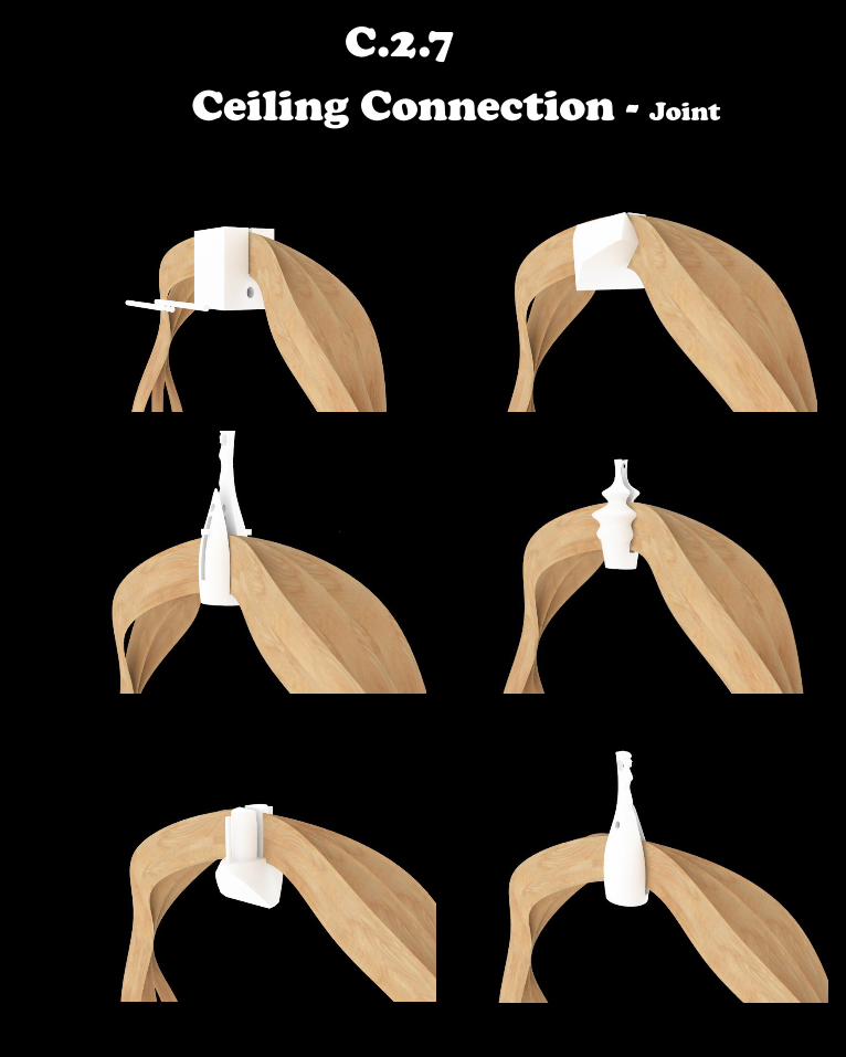
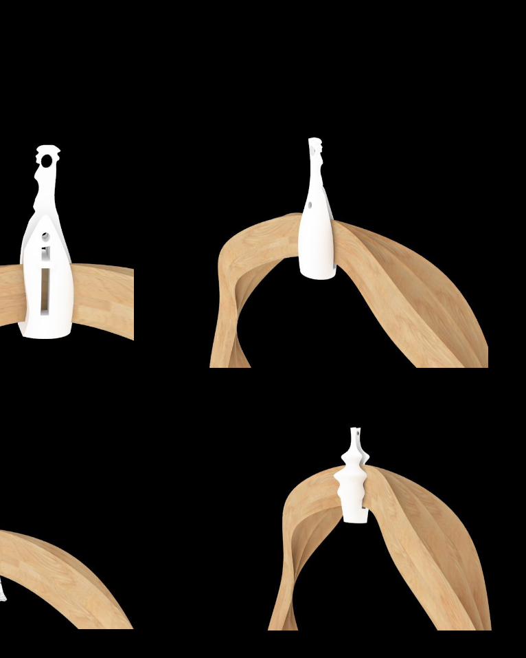
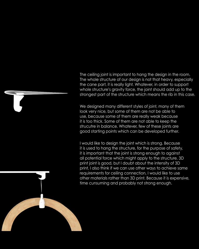
The ceiling joint is important to hang the design in the room. The whole structure of our design is not that heavy, especially the cane part, it is really light. Whatever, in order to support whole structure’s gravity force, the joint should add up to the strongest part of the structure which means the rib in this case.
We designed many different styles of joint, many of them look very nice, but some of them are not be able to use, because some of them are really weak because it is too thick. Some of them are not able to keep the strucutre in balance. Whatever, few of these joints are good starting points which can be developed further.
I would like to design the joint which is strong. Because it is used to hang the structure, for the purpose of safety, it is important that the joint is strong enough to against all potential force which might apply to the structure. 3D print joint is good, but I doubt about the intensity of 3D print, I also think if we can use other ways to achieve same requirements for ceiling connection, I would like to use other materials rather than 3D print. Because it is expensive, time cunsuming and probably not strong enough.
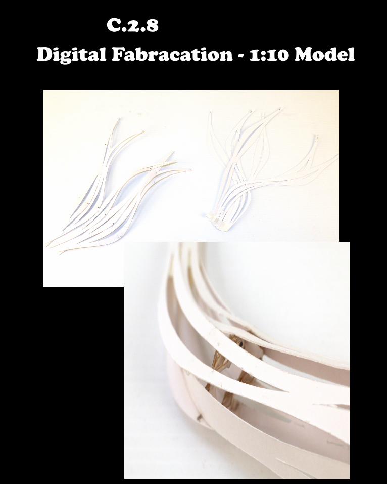
C.2.8 Digital Fabracation - 1:10 Model


C.3 Final Detail Model

C.3 Final Detail Model

C.3. Final Overall 3D print model


C.4 Learning Objectives and Outcomes
C.4 Learning Objectives and Outcomes
C.4 Learning Outcomes
As a group work, we start all most everything from beginning, exppecially my group design from part b is not selected to develop in part C.
We work in a big group, it is amazing that we combine everyone’s idea to our final design in only three weeks, In this period, everyone works well one their own work and tries to contribute their part to the final design. It can be said that the final outcome is consisted by everyone’s effort. It is a good experience to work in a big group like this. It gives sense of how to work in a group and connect all people in a group as integrity.
However, we don’t get a very good result. The lack of conherence within the project is saw clearly. Because everyone is responsible for only one part of the design, so it looks everything in our project is over-designed. Furthermore, because we are not working together as a team, so the continuity of design is not that good. Because everyone just aim one direction, so it is hard for us to consider others’ part as whole, that makes us can’t make a final entire model because we can’t assemble all parts together. The lack of communication is true, if everyone just work together day and night as an architectural team, I think it will be much better. I agree about the feedback from the presentation, comparing to the groups in other class, we are better at the detail element design, but bad at the overall design and model making.
I like the experience that all people work in a group, sharing ideas and giving inspiration to each other. We are working well at the design for each section but just not good enough to combine them together logicly. I believe if we have more time, our design could be much better.

C.4 Learning Outcomes
Back to myself. Through the semester, I develop an understanding of computional design and parametric design. As a complex design approach, I believe studio air is just a beginning. In this semester, I already have the understanding of computional design process. How to move step by step from design concept to digital model to physical model. How to express my idea through the model, diagram and analysis. How to improve my design by testing and analyzing. I understand it has a long process to make a idea or concept to the final real design, but the process is intereting and necessary for an architectural student.
Through my joint design in part C, I undertad the process to improve my joint in order to satisfy the needs from design concept. I learn that we can find the inspiration from life, everything like the connection of table could be useful for my design, all I need to do is bring the inspiration and reform it too fit my design, it is impossible that I can design a good thing straight way. There are always some errors in my design which I need to solve them one by one until get the final most suitable result.
I have learnt a lot of things through the semester. I understand the computation from Rhino and grasshopper, I understand the logic inside the computational design tools and how to use these tools to assist my design. It is good to see my improvement in this semester, I have very less ideas about the Rhino and grasshopper before, but now I am okay to make something which is in my mind in Rhino by using grasshopper and express them in a effective way. Thank you a lot for the helps through the semster. I will keep develop my techniques in future.


![Index []...Autumn Semester classes resume Autumn Semester Make-up Classes Autumn Semester Final Exams schedule available on Loyola Autumn Semester classes end Autumn Semester Final](https://static.fdocuments.net/doc/165x107/5eccb0aaa0af283cb576e713/index-autumn-semester-classes-resume-autumn-semester-make-up-classes-autumn.jpg)