Self-powered and low mass autonomous platform for ... · Este paradigma de exploraci´on ......
252
UNIVERSIDAD CARLOS III DE MADRID TESIS DOCTORAL Self-powered and low mass autonomous platform for planetary surface exploration Autor: Francisco Javier ´ Alvarez Fern´ andez Director: Luis Enrique Moreno Lorente Codirector: Diego Fern´ andez Infante DEPARTAMENTO DE INGENIER ´ IA DE SISTEMAS Y AUTOM ´ ATICA Legan´ es, Febrero 2016
Transcript of Self-powered and low mass autonomous platform for ... · Este paradigma de exploraci´on ......
UNIVERSIDAD CARLOS III DE MADRID
TESIS DOCTORAL
Self-powered and low massautonomous platform for
planetary surface exploration
Autor:Francisco Javier Alvarez Fernandez
Director:Luis Enrique Moreno Lorente
Codirector:Diego Fernandez Infante
DEPARTAMENTO DE INGENIERIA DE SISTEMAS Y
AUTOMATICA
Leganes, Febrero 2016


TESIS DOCTORAL (THESIS)
Self-powered and low mass autonomous platform for
planetary surface exploration
Autor (Candidate): Francisco Javier Alvarez Fernandez
Director (Adviser): Luis Enrique Moreno LorenteCodirector (Co-Adviser): Diego Fernandez Infante
Tribunal (Review Committee)
Javier Gomez-Elvira Rodrıguez. Presidente (Chair):
Ernesto Gambao Galan. Vocal (Member):
Marıa Dolores Blanco Rojas. Secretario (Secretary):
Calificacion (Qualification):
Tıtulo (Grade): Doctorado en Ingenierıa Electrica, Electronica y Automatica
Leganes, de Febrero de 2016


Abstract
Nowadays and during the following decades, planetary surface exploration of rockybodies in our Solar System (especially the Moon, Mars and some asteroids), will beone of the main strategic goals for the different space agencies around the world. Thisthesis stablishes the technological basis for the implementation of a fixed scientificmonitoring infrastructure over a planet surface. The concept proposed is aimed toprovide a reliable and cost effective system for the continuous surface monitoring ofthe inner rocky planets of our Solar System.
Traditionally these surface exploration missions have been led by progressivelymore and more complex and expensive systems with challenging scientific andtechnological objectives (i.e. NASA Mars rovers, ESA ExoMars program or theChinese Chang’e 3 mission). This space exploration paradigm benefits fromdeploying highly ambitious and expensive platforms able to perform complexscientific experiments, but it is exposed to the risk of a complete mission loss in thecase of a platform failure.
Beyond the traditional rovers or landers, the concept proposed is based onan ad-hoc Wireless Sensor Network composed of small fixed platforms aimed tosense, process, share between them and finally transmit scientific data to a satelliteorbiter for further transmission to Earth. The conceived system is able to operateautonomously during years, harvesting the required energy from the planet surfaceenvironment. Such a concept deployed over a planet surface would represent the firstfixed infrastructure over an extraterrestrial rocky body.
This work is focused in the platform overall design, including the ad-hoc scientificpayload, and provides reliable technological solutions for the different critical aspectsof the concept proposed.
The platform conceived is a low mass dual body: (i) a tetrahedron body highlyoptimized both in mass (2000g) and volume (tetrahedron envelope of 200x200 mm ofbase and 200 mm of height) that will remain over the planet surface; (ii) a penetratorbody (3260 g) of 300 mm in height, 100 mm in diameter and with the shape ofa ballistic missile aimed to go between 0.3 and 1.2 meters below the subsurface of
i

the planet. The deployment method selected is penetration (hard-landing). Thismethod drastically simplifies the descent system required, thus reducing the relatedcosts. Specific solutions for the conceived platform are proposed with the objectiveof ensuring the platform operability after the landing impact.
The scientific payload conceived is highly integrated with low power consumptionrequirements. The payload presented in this work comprises a dust depositionsensor, three surface temperature sensors, a radiation sensor and three multiespectralirradiance sensors.
Day and night energy harvesting systems are proposed, which represents aninnovation in this kind of platforms.
Finally, a specific control architecture is presented aimed to provide the requiredautonomous behavior to the platform. This autonomous behavior in combinationwith a dynamic thermal regulation and the day and night energy harvesting systemsallow the platform conceived to drastically increase its science return and life time.
ii

Resumen
En la actualidad y durante las proximas decadas, la exploracion de las superficiesplanetarias de los cuerpos rocosos de nuestro Sistema Solar (especialmente de laLuna, Marte y la de algunos asteroides), sera uno de los objetivos estrategicos delas diferentes agencias espaciales de todo el mundo. Esta tesis establece las basestecnologicas para la implantacion de una infraestructura de monitorizacion cientıficasobre la superficie de un planeta. El concepto propuesto esta orientado a obtener unsistema fiable y economico para la monitorizacion continua de la superficie planetariade los cuerpos rocosos internos de nuestro Sistema Solar.
Tradicionalmente este tipo de exploracion de superficies planetarias ha sidollevada a cabo por sistemas cada vez mas y mas complejos y costosos (por ejemplo losvehıculos exploradores para Marte de la NASA, el programa ExoMars de la AgenciaEspacial Europea o la mision china Chang’e 3). Este paradigma de exploracionespacial aprovecha la oportunidad de desplegar plataformas muy complejas yambiciosas capaces de realizar complejos experimentos cientıficos, pero expuestas alriesgo de la perdida completa de la mision en caso de un fallo en la plataforma deexploracion.
Mas alla de los tradicionales vehıculos exploradores o sondas, el conceptopropuesto se basa en pequenas plataformas capaces de medir, procesar, compartirentre ellas y finalmente enviar los datos medidos a un satelite en orbita para unaposterior transmision a la Tierra, mediante el uso de redes de sensores inalambricosa medida. El sistema ideado es capaz de operar autonomamente durante anos,recolectando la energıa requerida en el propio ambiente de la superficie del planeta.Este tipo de concepto, desplegado sobre la superficie de un planeta, representarıa laprimera infraestructura fija sobre la superficie de un cuerpo rocoso extraterrestre.
El trabajo presentado se enfoca en el diseno global de la plataforma, incluyendo lainstrumentacion cientıfica y aporta soluciones tecnicas para los aspectos mas crıticosdel concepto propuesto.
La plataforma ideada esta basada en dos cuerpos: (i) un cuerpo con formatetraedrica muy optimizado en peso (2000 gr) y en volumen (envolvente del tetraedro
iii

de 200x200 mm de base y 200 mm de altura) que permanecera en la superficie delplaneta; (ii) el cuerpo del penetrador (3260 gr) de 300 mm de altura, 100 mm dediametro y con la forma de un misil balıstico enfocado a enterrarse entre 0.3 y 1.2metros por debajo de la superficie del planeta. El sistema de despliegue seleccionado esla insercion (�aterrizaje duro�del ingles �hard-landing�), simplificando drasticamentede esta forma el sistema de descenso requerido, y por lo tanto reduciendo los costesasociados. Se proponen igualmente soluciones especıficas para la plataforma ideadade forma que se asegure su integridad operacional despues del impacto durante elaterrizaje.
Se ha definido una instrumentacion cientıfica altamente integrada y con unosrequisitos de consumo muy bajos. La instrumentacion desarrollada consta de unsensor de polvo depositado, tres sensores de temperatura superficial, un sensor deradiacion y tres sensores de irradiacion multiespectral.
Se proponen asimismo sistemas de obtencion de energıa durante el dıa y la noche,lo que representa una innovacion en este tipo de plataformas. Finalmente, se presentauna arquitectura de control especıfica enfocada a proporcionar a la plataforma elcomportamiento autonomo que se requiere. Este comportamiento autonomo encombinacion con un sistema dinamico de regulacion termica y de los sistemas deobtencion de energıa durante el dıa y la noche permite a la plataforma concebidaincrementar en gran medida la informacion cientıfica obtenida y la vida util de lamision en su conjunto.
iv

A mis padres.
v

Agradecimientos
Es difıcil incluir en una pocas lıneas la gran ayuda recibida, tanto personalcomo profesional, para la consecucion de este trabajo. Por ello, y sabiendo queinevitablemente no podre mencionar a todos, haceros llegar mi gratitud mas sincerapor vuestra ayuda.
En primer lugar me gustarıa agradecer a mis tutores, Luis y Diego, que meapoyaron y acompanaron desde los inicios, y no me refiero solo a este trabajo, sinodesde hace ya mas de 10 anos en los diferentes proyectos fin de carrera y tesinas quehe ido realizando. Gracias por vuestra confianza.
Quiero agradecer al equipo del Grupo Arquimea Ingenierıa, desde el primerohasta el ultimo, su gran ayuda en estos anos en los que hemos ido creciendo juntosprofesionalmente en el mundo del I+D. Especialmente me gustarıa agradecer aCayetano sus inestimables aportaciones a este trabajo, no solo en el ambito delos mecanismos disenados, sino tambien por todo su apoyo. No quiero olvidarmede Carlos y Jesus, disenadores del ASIC de radiacion y que perdieron algun queotro fin de semana por llegar a tiempo para la fabricacion de los mismos. GraciasNaiara, Marcelo, Paco y Dani por vuestras correcciones y comentarios en las diferentespublicaciones y en este mismo trabajo. Agradecer igualmente a David sus indicacionespara la electronica del sensor de polvo. Aunque ya no esta entre nosotros porque pasoa una mejor vida (en las soleadas costas de Florida), agradecer a Lorenzo su ayuda yconfianza durante los inicios de esta tesis.
No puedo dejar de incluir aquı mis agradecimientos al grupo de trabajo delproyecto europeo SWIPE: �My most sincere gratitude to the SWIPE Project team:thank you for your great collaboration �.
Gracias a mi hermano, a mi sobrino por arrancarme sonrisas y a mis padres porllevarme hasta aqui. Finalmente, quiero agradecer a Stephy no solo toda su ayuda,apoyo y carino durante estos anos, sino tambien por haberme aguantado, lo cual esmucho mas complejo que cualquiera de los conceptos aquı propuestos.
A todos, gracias.
vii

viii

Abbreviations
AI - Artificial IntelligenceASIC - Application-Specific Integrated CircuitAU - Astronomical UnitCAD - Computer-Aided DesignCOSPAR - Committee on Space ResearchDDS - Dust Deposition SensorDHMR - Dry Heat Microbial ReductionDLR - German Aerospace CentreDM - Descent ModuleDS2 - Deep Space 2EM - Engineering ModelEoL- End of LifeFPGA - Field-Programmable Gate ArrayFM - Flight ModelGS - Ground SegmentGSP - General Studies ProgrammeIR - Infra-RedISAS - Institute of Space and Astronautical ScienceITAR - International Traffic in Arms RegulationsLED - Laser Emitting DiodeLEO - Low Earth OrbitLoS - Line-of-SightMANET - Mobile wireless Ad hoc NETworksMIT - Massachusetts Institute of TechnologyMLI - Multi-Layer InsulationMMRTG - Multi-Mission Radioisotope Thermoelectric GeneratorMNL - Met-Net LanderMPL - Mars Polar LanderPCB - Printed Circuit BoardPDS - Penetrator Delivery System
ix
PEM - Proton Exchange MembranePSRR -Power Supply Rejection RatioQM - Qualification ModelREACT - REsettable Hold-Down and Release ACTuatornR&D - Research and DevelopmentRTG - Radioisotope Thermoelectric GeneratorSEB - Single-Event BurnoutSEGR - Single-Event Gate RuptureSEL - Single-Event Latch-upSEFI - Single Event Functional InterruptSET - Single Event TransientsSEUs - Single Effect UpsetsSMA - Shape Memory AlloySOC - State of ChargeSPOF - Single Point of FailureSS- Space SegmentSWIPE - Space WIreless sensor networks for Planetary ExplorationTEG - Thermoelectric GeneratorTID - Total Ionizing DoseTMM - Thermal Mathematical ModelTRL - Technology Readiness LevelUC3M - Carlos III University of MadridUV - Ultra-VioletVIS - Visible
x

Contents
Abstract i
Resumen iii
Agradecimientos vii
Abbreviations ix
1 Motivation 11.1 Space research motivation general outline . . . . . . . . . . . . . . . 31.2 Cost . . . . . . . . . . . . . . . . . . . . . . . . . . . . . . . . . . . . 41.3 Planetary surface environmental constrains . . . . . . . . . . . . . . . 81.4 Motivation summary . . . . . . . . . . . . . . . . . . . . . . . . . . . 15
2 Objectives 172.1 Objectives description . . . . . . . . . . . . . . . . . . . . . . . . . . 192.2 Objectives considerations . . . . . . . . . . . . . . . . . . . . . . . . . 22
3 Research approach 233.1 Research framework . . . . . . . . . . . . . . . . . . . . . . . . . . . . 25
3.1.1 SWIPE: FP–7 project . . . . . . . . . . . . . . . . . . . . . . 253.2 General outline of the proposed solution . . . . . . . . . . . . . . . . 26
3.2.1 The Moon: selection as target scenario for technologiesdemonstration . . . . . . . . . . . . . . . . . . . . . . . . . . . 31
4 State of the Art 334.1 State of the art in small platforms for planetary exploration . . . . . 35
4.1.1 The Lunar-A mission . . . . . . . . . . . . . . . . . . . . . . . 354.1.2 UK Penetrator Consortium (MoonLITE mission) . . . . . . . 364.1.3 Deep Space 2 . . . . . . . . . . . . . . . . . . . . . . . . . . . 374.1.4 Luna-Glob . . . . . . . . . . . . . . . . . . . . . . . . . . . . . 40
xi
4.1.5 Met-Net . . . . . . . . . . . . . . . . . . . . . . . . . . . . . . 414.1.6 RF-WIPE . . . . . . . . . . . . . . . . . . . . . . . . . . . . . 434.1.7 Hopping robots . . . . . . . . . . . . . . . . . . . . . . . . . . 43
4.2 State of the art analysis . . . . . . . . . . . . . . . . . . . . . . . . . 48
5 Self–powered and low mass fixed platform 535.1 Platform configuration . . . . . . . . . . . . . . . . . . . . . . . . . . 555.2 Surface tetrahedral platform description . . . . . . . . . . . . . . . . 58
5.2.1 Tetrahedron shape selection . . . . . . . . . . . . . . . . . . . 585.2.2 Inner electronics bay . . . . . . . . . . . . . . . . . . . . . . . 615.2.3 Scientific payload distribution . . . . . . . . . . . . . . . . . . 625.2.4 Solar panels deployment subsystem . . . . . . . . . . . . . . . 63
5.3 Penetrator body description . . . . . . . . . . . . . . . . . . . . . . . 645.4 Harnessing . . . . . . . . . . . . . . . . . . . . . . . . . . . . . . . . . 655.5 Redundancy considerations . . . . . . . . . . . . . . . . . . . . . . . . 675.6 Main and redundant On Board Computer architecture overview . . . 715.7 Platform mass budget . . . . . . . . . . . . . . . . . . . . . . . . . . 73
6 Scientific low mass and low power consumption payload 776.1 Scientific payload conceived . . . . . . . . . . . . . . . . . . . . . . . 796.2 Dust Deposition Sensor . . . . . . . . . . . . . . . . . . . . . . . . . . 80
6.2.1 Introduction and requirements definition . . . . . . . . . . . . 806.2.2 Proposed Dust Deposition Sensor design . . . . . . . . . . . . 80
6.3 Radiation sensor . . . . . . . . . . . . . . . . . . . . . . . . . . . . . 856.3.1 Introduction and requirements definition . . . . . . . . . . . . 856.3.2 Proposed radiation sensor design . . . . . . . . . . . . . . . . 87
6.4 Multispectral Irradiance sensor . . . . . . . . . . . . . . . . . . . . . 906.4.1 Introduction and requirements definition . . . . . . . . . . . . 906.4.2 Mathematical model for Moon�s surface solar irradiance
estimation . . . . . . . . . . . . . . . . . . . . . . . . . . . . 926.4.3 Proposed Multispectral Irradiance Sensor design . . . . . . . . 96
6.5 Surface temperature sensor . . . . . . . . . . . . . . . . . . . . . . . . 996.5.1 Introduction and requirements definition . . . . . . . . . . . . 996.5.2 Mathematical model for lunar Surface temperature estimation 996.5.3 Proposed lunar surface temperature sensor . . . . . . . . . . . 1036.5.4 Scientific payload acquisition electronics . . . . . . . . . . . . 106
7 Solutions for the deployment of a large number of robotic platformsover the planet surface 1137.1 Trade-off of platform deployment methods . . . . . . . . . . . . . . . 1157.2 Platform deployment: solution conceived . . . . . . . . . . . . . . . . 117
xii

7.2.1 General overview . . . . . . . . . . . . . . . . . . . . . . . . . 117
7.2.2 The descent phase and descent module . . . . . . . . . . . . . 119
7.2.3 The surface impact: configuration and high impact survivaltechniques proposed. . . . . . . . . . . . . . . . . . . . . . . . 122
8 Thermal design: conceived technologies for thermal regulation ofthe exploration platform 129
8.1 Thermal design introduction and objectives . . . . . . . . . . . . . . 131
8.2 Thermal Mathematical Model . . . . . . . . . . . . . . . . . . . . . . 132
8.2.1 The energy balance . . . . . . . . . . . . . . . . . . . . . . . . 132
8.2.2 Platform multi-node discretization . . . . . . . . . . . . . . . 135
8.3 Thermal design solutions and model results . . . . . . . . . . . . . . . 139
9 Energy management and innovative concepts for energy harvesting.147
9.1 Energy harvesting for space exploration . . . . . . . . . . . . . . . . . 149
9.2 Energy management and energy consumption mathematical model . . 150
9.3 Solutions proposed for energy harvesting . . . . . . . . . . . . . . . . 153
9.3.1 Energy harvesting for space exploration . . . . . . . . . . . . . 155
9.3.2 Thermoelectric generator . . . . . . . . . . . . . . . . . . . . 156
9.3.3 Solar energy harvesting . . . . . . . . . . . . . . . . . . . . . . 166
10 High level control architecture 173
10.1 Control architecture introduction . . . . . . . . . . . . . . . . . . . . 175
10.2 The sequencer . . . . . . . . . . . . . . . . . . . . . . . . . . . . . . . 178
10.3 World model estimator . . . . . . . . . . . . . . . . . . . . . . . . . . 182
10.4 The planning layer: Automated planning and checker . . . . . . . . . 184
10.5 The control layer . . . . . . . . . . . . . . . . . . . . . . . . . . . . . 187
11 Platform prototyping and laboratory test results 189
11.1 Platform prototyping introduction . . . . . . . . . . . . . . . . . . . . 191
11.2 Tetrahedral platform structure . . . . . . . . . . . . . . . . . . . . . 192
11.3 Solar panels deployment system, functional tests and results . . . . . 194
11.4 Scientific payload prototype functional tests and results . . . . . . . . 195
11.4.1 Dust Deposition Sensor prototype and laboratory tests results 195
11.4.2 Irradiance sensor prototype and laboratory test results . . . . 200
11.4.3 Surface temperature sensor prototype and laboratory test results202
11.4.4 Acquisition electronics prototype . . . . . . . . . . . . . . . . 204
11.5 Thermal switch prototype functional tests and results . . . . . . . . . 204
xiii

12 Conclusions and future research 20912.1 Conclusions . . . . . . . . . . . . . . . . . . . . . . . . . . . . . . . . 21112.2 Future research . . . . . . . . . . . . . . . . . . . . . . . . . . . . . . 213
Bibliography 215
xiv

List of Tables
1.1 Temperature, gravity and atmospheric pressure characteristics of mainsolar system rocky bodies (data obtained from [WB4] and [Heikenet al., 1991]) . . . . . . . . . . . . . . . . . . . . . . . . . . . . . . . . 12
1.2 Dust main effects over planetary surface systems . . . . . . . . . . . . 13
4.1 State of the art comparative table . . . . . . . . . . . . . . . . . . . . 50
5.1 Platform redundancy summary . . . . . . . . . . . . . . . . . . . . . 725.2 Platform mass budget . . . . . . . . . . . . . . . . . . . . . . . . . . 75
6.1 List of commands for the acquisition electronics . . . . . . . . . . . . 111
8.1 Platform thermal coupling node matrix . . . . . . . . . . . . . . . . . 1378.2 Parameters used in the Thermal Mathematical Model . . . . . . . . . 138
9.1 Platform subsystems power consumption estimation . . . . . . . . . . 1529.2 Energy consumption mathematical model equations . . . . . . . . . . 1539.3 TEG for the lunar platform exploration characteristics . . . . . . . . 1649.4 TEG designed output characteristics for steady state condition (Th =
250, 15K and Tc = 100K and RL = RTEG) . . . . . . . . . . . . . . . 1659.5 Solar panels parameters construction . . . . . . . . . . . . . . . . . . 169
10.1 Control layer hardware operations. . . . . . . . . . . . . . . . . . . . 188
11.1 Power consumption DDS actuator test results. . . . . . . . . . . . . . 19611.2 Summary of results obtained during the two DDS laboratory test
campaigns. . . . . . . . . . . . . . . . . . . . . . . . . . . . . . . . . . 199
xv


List of Figures
2.1 hayabusa . . . . . . . . . . . . . . . . . . . . . . . . . . . . . . . . . . 20
4.1 Lunar A mission . . . . . . . . . . . . . . . . . . . . . . . . . . . . . 36
4.2 MoonLITE . . . . . . . . . . . . . . . . . . . . . . . . . . . . . . . . 37
4.3 DS2 . . . . . . . . . . . . . . . . . . . . . . . . . . . . . . . . . . . . 39
4.4 LunaGlob . . . . . . . . . . . . . . . . . . . . . . . . . . . . . . . . . 41
4.5 METNET . . . . . . . . . . . . . . . . . . . . . . . . . . . . . . . . . 43
4.6 Canadian Space Agency hopping mechanism (extracted from[Montminy et al., 2008] . . . . . . . . . . . . . . . . . . . . . . . . . . 44
4.7 hayabusa . . . . . . . . . . . . . . . . . . . . . . . . . . . . . . . . . . 47
5.1 closedplatform . . . . . . . . . . . . . . . . . . . . . . . . . . . . . . . 56
5.2 openplatform . . . . . . . . . . . . . . . . . . . . . . . . . . . . . . . 57
5.3 25 N pin puller based on SMA . . . . . . . . . . . . . . . . . . . . . . 63
5.4 Harness . . . . . . . . . . . . . . . . . . . . . . . . . . . . . . . . . . 66
5.5 umbilical . . . . . . . . . . . . . . . . . . . . . . . . . . . . . . . . . . 67
5.6 OBC . . . . . . . . . . . . . . . . . . . . . . . . . . . . . . . . . . . . 73
6.1 dust Moon . . . . . . . . . . . . . . . . . . . . . . . . . . . . . . . . . 81
6.2 esquema DDS . . . . . . . . . . . . . . . . . . . . . . . . . . . . . . . 82
6.3 DDS and auxiliary electronics. Functional prototype. . . . . . . . . . 84
6.4 radiation moon . . . . . . . . . . . . . . . . . . . . . . . . . . . . . . 86
6.5 rad scheme . . . . . . . . . . . . . . . . . . . . . . . . . . . . . . . . . 89
6.6 radfet . . . . . . . . . . . . . . . . . . . . . . . . . . . . . . . . . . . 90
6.7 Radiation sensor functional prototype (RADFET not included) . . . 90
6.8 Solar Irradiance spectra for a total integrated irradiance of1367.28�0.02 W/m2 (Extracted from [Tobiska et al., 2000]) . . . . . . 91
6.9 geome . . . . . . . . . . . . . . . . . . . . . . . . . . . . . . . . . . . 94
6.10 irr . . . . . . . . . . . . . . . . . . . . . . . . . . . . . . . . . . . . . 96
xvii

6.11 Solar Irradiance at 90◦ latitude (top) and −90◦ latitude (center)obtained with the model developed for year 1994. Solar irradianceresults for year 1994 extracted from [Badescu, 2012], chapter 15. NorthPole (solid line, bottom figure) and South Pole (dotted line, bottomfigure) . . . . . . . . . . . . . . . . . . . . . . . . . . . . . . . . . . . 97
6.12 Disposition of the irradiance sensors on the platform structure (topview). . . . . . . . . . . . . . . . . . . . . . . . . . . . . . . . . . . . 97
6.13 Photodiodes selected for the multispectral irradiance sensor ([Pacific-Silicon-Sensor, 2010], and [GmbH, 2013] [Optoelectronics, 2015]) 98
6.14 Front end electronics (Photovoltaic mode). . . . . . . . . . . . . . . . 996.15 Thermal balance sketch . . . . . . . . . . . . . . . . . . . . . . . . . . 1016.16 Lunar surface temperature at equator (bottom left) and 80◦N (top left)
in one year extracted from [Li et al., ] compared with results obtainedfor year 2015 with the model developed at the equator (bottom right)and at 80◦N (top right). . . . . . . . . . . . . . . . . . . . . . . . . . 103
6.17 Model calculations of lunar surface temperature variations as a functionof local time and latitude extracted from [Paige et al., 2010] after[Vasavada et al., 1999]. Local time is expressed in lunar hourswhich correspond to 1/24 of a lunar month. At 89◦ latitude, diurnaltemperature variations are shown at summer and winter solstices(bottom). Results obtained using the model herein developed (top). . 104
6.18 Temperature probes for lunar surface temperature monitoring (left)and selected thermistor P1K0.232.6w.A.010 ( [IST, 2014]) (right) . . 105
6.19 Temperature sensors front end electronics and Voltage output range infunction of the PTC resistance values . . . . . . . . . . . . . . . . . . 105
6.20 Low power/low mass acquisition electronics block diagram . . . . . . 108
7.1 Highly schematic cross-section illustrating the idealized effects oflarge-scale cratering on the structure of the upper lunar crust.(Extracted from [Heiken et al., 1991] . . . . . . . . . . . . . . . . . . 117
7.2 Section of the pressurized compartment and the clamp band systemconceived for docking the tetrahedral platform to the Descent Module(Descent Module based in the concept proposed by the UK PenetratorConsortium, [Gowen et al., 2011] and used as example of DescentModule in the figure) . . . . . . . . . . . . . . . . . . . . . . . . . . 121
7.3 Schematic section of the tetrahedral platform illustrating the differentcohesion materials used for shock protection . . . . . . . . . . . . . . 126
7.4 Compression curve for metal foam (schematic extracted from [Ashbyet al., 2000]) . . . . . . . . . . . . . . . . . . . . . . . . . . . . . . . . 128
8.1 Isothermal nodes selection for the platform thermal model . . . . . . 135
xviii
8.2 Thermal switch model . . . . . . . . . . . . . . . . . . . . . . . . . . 139
8.3 SMA based thermal switch (7mm in height and 111 mm in diameter). 140
8.4 Thermal nodes temperature evolution during approximately 1 lunarday considering 0W dissipation. . . . . . . . . . . . . . . . . . . . . 142
8.5 Thermal nodes temperature evolution during approximately 1 lunarday considering 0.2 W continuous power dissipation in the innerelectronics bay. . . . . . . . . . . . . . . . . . . . . . . . . . . . . . . 143
8.6 Thermal nodes temperature evolution during approximately 1 lunarday considering 2 W power dissipation during 10 hours in the innerelectronics bay for a punctual measurement during the lunar night. . 145
9.1 Overview of the harvesting techniques conceived for the platform . . . 154
9.2 Mean substrate temperature at the four probes from the Apollomissions in function of depth (extracted from [Langseth et al., 1976]). 155
9.3 Commercial thermoelectric generator system from Marlow Industries( [Marlow Industries, 2015], model XLT6-4-01LS) (left) and schematicsection of a TEG (right), extracted from [LeBlanc, 2014]. . . . . . . . 157
9.4 Proposed metal wires bundle sketch . . . . . . . . . . . . . . . . . . 159
9.5 First and second derivative Seebeck coefficients for type Jthermocouples in function of the temperature (extracted from [Powellet al., 1974]) . . . . . . . . . . . . . . . . . . . . . . . . . . . . . . . . 161
9.6 TEG performance during one lunar cycle . . . . . . . . . . . . . . . . 166
9.7 Solar power generated per solar panel (top), total power generated byall the solar panels (centre) and solar incident angle (bottom). Dataobtained for January 2016, 0�latitude,0�longitude and solar panel 1facing the lunar equator. . . . . . . . . . . . . . . . . . . . . . . . . . 170
9.8 Maximum solar power harvested for January 2006 in function of theincreasing latitude towards North Pole (top); and maximum solar angleof the Sun in function of the latitude (bottom) . . . . . . . . . . . . . 171
10.1 Traditional remote control and proposed control scheme. . . . . . . . 176
10.2 High level control architecture proposal. . . . . . . . . . . . . . . . . 178
10.3 Proposed sequencer flowchart. . . . . . . . . . . . . . . . . . . . . . . 179
10.4 OBC status checking subroutines between the redundant OBC andmain OBC. . . . . . . . . . . . . . . . . . . . . . . . . . . . . . . . . 182
10.5 Planning algorithm scheme overview. . . . . . . . . . . . . . . . . . . 186
11.2 Node structure assembled (left). Upper structure with PP assembled(center). Lower structure with electronics rack integrated (right). . . 192
xix

11.1 SWIPE node platform without solar panels (top); SWIPE node withsolar panels closed and power cable (bottom left) and open with powercable removed (bottom right). . . . . . . . . . . . . . . . . . . . . . . 193
11.3 Solar panels deployment sequence. . . . . . . . . . . . . . . . . . . . . 19411.4 Low temperature tests. . . . . . . . . . . . . . . . . . . . . . . . . . . 19511.5 DDS actuator activation sequence at ambient temperature. . . . . . . 19611.6 5μm samples with a different dust particles distribution over the optical
window (top); 100μm Corundum sample (bottom right); and 100μmglass microspheres sample (bottom left). . . . . . . . . . . . . . . . . 197
11.7 100μm Corundum dust particles suspension and samples prepared fordry in the oven at 85�C. . . . . . . . . . . . . . . . . . . . . . . . . . 198
11.8 Assembled irradiance sensor. . . . . . . . . . . . . . . . . . . . . . . . 20011.9 Optical test bench (left and center) and measurements at ambient light
(right). . . . . . . . . . . . . . . . . . . . . . . . . . . . . . . . . . . . 20111.10Temperature probe prototype details . . . . . . . . . . . . . . . . . . 20211.11Calibration of temperature sensor. 0�C top and 100�C bottom. . . . . 20311.12Acquisition electronics PCB (left) and acquisition electronics
integrated in the SWIPE structure (right). . . . . . . . . . . . . . . . 20511.13Thermal switch test set-up. . . . . . . . . . . . . . . . . . . . . . . . 20511.14Thermal vacuum test results. . . . . . . . . . . . . . . . . . . . . . . 206
xx

Chapter 1
Motivation
1


1.1. Space research motivation general outline 3
Planetary surface exploration using robotic systems became a reality in the lastcentury; nevertheless we have just scratched the surface of a vast field of the scienceand engineering.
In this chapter a general overview of the main drivers of space exploration is given,focusing on the reasons that motivate the development of new technologies able toreduce the overall cost mission for planetary surface exploration. Particularly, theanalysis is focused on the necessity of developing new technologies with low mass andlow power consumption with the objective of reducing the costs of future planetaryexploration missions using robotic systems.
1.1 Space research motivation general outline
Space exploration and more specifically planetary surface exploration representsnowadays one of the most challenging and effort demanding dares for the humanity.Space exploration is usually followed by controversy due to the high cost and effortsrequired to perform advances in our knowledge of the outer space, when in our ownworld there are innumerable scientific and engineering challenges to face. Besides thehigh cost and high demanding efforts required it is important to consider the followingmain significant returns that the space exploration generates:
� Development of new technologies and science reinforcement that used interrestrial applications enhances our quality of life. Space environmentalconstrains represents an extraordinary experimental platform for technologicalinnovation.
� Increase human understanding of the Earth origin, evolution and its place inthe Universe.
� Enable the exploitation of space natural resources, as telecommunicationcapabilities, by means of communication satellites or new possibilities of energyand material harvesting.
� Generation of links and cooperation between different nations worldwideby means of a common objective, that promote peaceful relations betweengovernments.
From centuries, astronomical observations from the Earth have providedimportant information about the bodies of our Solar System and beyond. Nowadaysthis exploration from our world is providing invaluable information year by yearobtaining fascinating findings. During the past fifty years different orbiter orfly-by missions have been used in order to provide fundamental information from

4 Chapter 1. Motivation
the different elements of our Solar System. The data gather by these meansincludes information that cannot been obtained from the observations from theEarth (imaging, magnetic, gravity and other remote sensing instruments operatingin gamma rays, X-rays, ultraviolet, visible, infrared or radio waves giving global andsynoptic data of the explored bodies ( [Bhandari, 2008], p.190).
The following step, previous to direct exploration by humans, is the surfaceexploration by robotic systems. Robotic systems are used as reliable environmentalmonitoring systems for planetary surface exploration. During the past decades,several landing missions (including fix platforms as landers or mobile platformsas rovers) have performed experiments over the surface of different Solar Systembodies that gathered information about the body environment as precise surfacetemperature, pressure, mineralogical and chemical soil composition, solar irradianceconditions, atmosphere characterization . . .
Planetary surface exploration by robotic means is a challenging and costly activitydue to multiple hard constrains as explained in detail afterwards. Although, roboticexploration is indispensable for future manned missions.
This thesis is focused in the development of a new autonomous, SMA-actuated, lowmass and self-powered platform for planetary surface exploration with the objectiveof reducing the overall cost of planetary surface exploration. The cost reduction of theoverall mission is a prior objective in order to be able to afford the space exploration.
Nowadays, and during the following decades, missions to explore the planetarysurface of the rocky bodies in our Solar System (especially Moon, Mars and asteroids)will be one of the main strategic goals for the space agencies ( [Hufenbach et al.,2014]). This thesis is motivated due to the necessity to incorporate new low powerconsumption and low mass technologies able to work reliably in the harsh environmentof outer bodies exploration.
1.2 Cost
General space access costs
During the cold war, the space race (1955–1972) endorsed the investment ofenormous quantities of money in space research, been the technology the limitingfactor. The Soviet Union (USSR) and the United States (US) were the main playersin this investment. Nowadays, the cost has become the main driven factor for spaceexploration and the number and complexity of players in the space access have growndrastically, including private companies, conglomerate of different nations and evenresearch institutions as private Universities.

1.2. Cost 5
The transport cost to space depends on the launcher used and on the capacityof the launcher�s rocket (biggest rockets are more expensive). US dollars per poundto Low Earth Orbit (�/pound-LEO) is the main key parameter used to quantify thecosts related to transport mass to space. This cost is changing year by year due tothe different private and public organizations that provide transport capabilities tospace. Therefore, reducing the mass of the space systems is a straightforward way ofreducing the mission costs. Transport cost just represents a part of the total costsrequired to develop space systems, other relevant actors that determinate the spacemission costs are:
� Reliability. Reliability is a main driver of aerospace designs. A high reliabilitydesign implies that all the systems and subsystems developed shall consider highsafety factors and procedures to comply with the mission constrains. Moreover,the systems (and all the elements, materials or parts that conforms them) shallbe subjected to a complex qualification and validation tests campaigns thatimply a huge cost in manufacturing prototypes, models for testing, facilities oftests, personnel, etc.
� Limited producers, reduced market and inability to large production.The availability of space qualified components is highly limited. The spacesector generates a reduced market in terms of units per year and usually theproduction techniques and the product itself is not compatible directly withnon-space applications. For these reasons the cost of recurrent componentsfor space application are between tens to hundreds times larger than theircommercial equivalents. Obviously this represents an important cost factorto be considered. Additionally we have to be aware that the delivery lead timescould be as large as 1 year or even more for certain components, what clearlyimplies a great impact for the mission scheduling.
Finally, it is important to note that the environmental conditions differdrastically from one planet to other and moreover are usually different fromthe outer space conditions. Most of the developed space technologies arefocused on the satellite market (operational phase is perform in outer spaceconditions), thus there is a lack of technologies or components available forplanetary surface exploration missions as the proposed in this work. A greatpart of the components used for planetary surface exploration missions have tobe qualified specifically for the mission with the consequent expenses.
� ITAR and other export restrictions. Components used in space marketare subjected also to ITAR (International Traffic in Arms Regulations) becauseof their potential use in military applications. Availability in Europe of some

6 Chapter 1. Motivation
space components developed in USA are occasionally limited, or the lead time isincreased due to the complex burocrazy in order to apply for an export license.
� Ground segment. During the lunch phase and mission phase, Earth facilities(control rooms, computers, high gain antennas for space signal tracking, etc.)and personnel shall be able to follow and command the space segment. Moreoverit is required to receive, gather and record the data during the missionexploitation phase. In most of the cases, analysis of the data gathered duringthe mission could take years after the mission ending.
� Additional infrastructure for planetary surface exploration.Infrastructure required for surface planetary exploration does not end withthe launchers and the ground segment. The communications infrastructurebetween the robotic system over the planet surface and the ground segmentis accomplished using communication satellites. An orbiter shall receive thedata from the surface exploration systems and transmit this data to Earth�sground segment network. Obviously this infrastructure represents a huge costand complexity and the deployment of orbiter satellites around the planet understudy are considered missions on their own.
Primary energy source selection, power consumption and massreduction as strategies for mission cost decrease.
Mass reduction strategy implies a direct cost reduction of the mission, reducingthe cost of space access as explained previously. Consequently innovative systems andsubsystems, as the proposed in this document, that could perform their functionalitiesreducing their mass with respect to traditional systems would decrease the missionoverheads. A main factor related to the system mass is the power consumption.Technologies that decrease their power consumption increase the system efficiencyand consequently reduce the power demand of the primary energy source, that canbe smaller, thus saving mass. Following this approach it is possible to go further:low power consumption could reach to the possibility of changing the primary energysource from one expensive with high performance to other with less capabilities andcheaper, reducing drastically the mission costs.
The primary energy source is known as the technology that converts from theenergy form found in the nature to electrical power by a transformation process. Ina satellite �primary energy source converts a fuel into electrical power�, [Fortescueet al., 2011], p.326.
Current technologies for planetary exploration are mainly based on RadioisotopeThermoelectric Generators (RTGs) as primary energy source. RTGs use the heat

1.2. Cost 7
generated from the natural decay of radioisotope materials (in USA systems mainlyPlutonium 238) and transform this heat into electricity thanks to the principle ofthermoelectric generation. Not only the electricity generated by the RTG is used,also the heat continuously generated in the RTG permits to heat the systems duringextreme cold conditions. As described in [Furlong and Wahlquist, 1999], there aremainly four reasons why RTGs have been used in several space exploration missionssince 1961:
� Long life. New developments at NASA (Multi-Mission RadioisotopeThermoelectric Generator or MMRTG) obtains lifetimes for this technologyas a minimum of 14 years.
� Environment. Nuclear power sources can operate in extreme environmentalconditions, even during night at very low temperatures (solar panels are justoperative with incident radiation). They are not affected by dust (e.g. solarpanels covered by dust reduce its efficiency depending on the quantity of dustdeposited over their surface).
� Operational independence. Apart from a temperature difference betweenthe surrounding environment and the RTG it does not require any externalelement to generate electricity.
� Reliability. Missions working up to three decades have proven the reliabilityof these power generators.
Europe is currently developing its own RTGs. As described in [Williams et al.,2012], Europe is focused on developing 241Am (Americium–241) as an alternativeisotope for future European RTGs.
However, besides the great advantages of RTGs, we have to consider two maindisadvantages in relation to the use of RTGs as primary energy source: cost andradiation contamination risk. RTGs are very expensive elements with low availability.The necessity of using radioisotope materials directly implies hard restrictions relatedto their procurement and final use that shall be managed by governments. Also wehave to consider that these materials are only available at long term (e.g. reducedavailability worldwide of Plutonium 238).
Additionally we have to consider the environmental impact of using radioisotopematerials not only just in the Earth, also in the environment of the planet understudy. Potential accidents that could result in the release of radioactive material in theenvironment shall be also considered. In [Dahl, 2006], we can find an environmentalimpact study as an example of the environmental impact of using RTGs in Earthand Mars. The development of new technologies with a low power consumption thatcould be powered using energy harvested over the planet surface could permit to

8 Chapter 1. Motivation
reduce drastically the cost of the mission and also would reduce the risk of potentialaccidents with radiative materials involved.
1.3 Planetary surface environmental constrains
Right after transportation, environmental conditions are the responsible of a greatpart of the elevated costs related to outer planets surface exploration. The reasonis because those environmental conditions are incompatible with the commercial,industrial or even military technologies developed for Earth operation. This meansthat specific technologies shall be developed to withstand the specific environmentalconditions of each individual mission. Furthermore the space systems shall completealmost three different environmental conditions or phases: pre-launch, launch andspace operation. In [Fortescue et al., 2011], p. 11 and following, it is possible to finda general description of the pre-launch and launch phases environmental constrains.Herein the environmental constrains of the operation phase are described specificallyfor the planetary surface exploration case.
Pending on each individual mission, the following environmental conditions willvary. In most of the cases the specific environmental conditions will imply a designconstraint that will require custom and innovative developments.
In the following paragraphs, the more important environmental factors involvedin space exploration that will play an important role in this thesis are presented,as main drivers for design decision making or as scientific measurement objectivesby themselves. During the dissertation of this thesis, the environmental parameterspresented below are described in detail for the lunar surface exploration environmentcase in order to determine boundary conditions for the technologies proposed. Belowa general overview of each parameter is described.
Radiation
We can briefly overview the natural space radiation environment differentiatingtwo main groups:
� Particles trapped by planetary magnetospheres including protons, electrons,and heavier ions of all of the elements of the periodic table.
� Transient radiation consisting of galactic cosmic rays (GCR mainly originatingoutside the Solar System are composed primarily of high-energy protons andatomic nuclei) and particles from solar events, such as coronal mass ejectionsand flares.

1.3. Planetary surface environmental constrains 9
The harmful radiation effects over the space exploration subsystems and crewshave been studied from the origin of the space exploration and nowadays are currentlyunder further analysis in numerous knowledge areas as physics, medics or engineering.
The effects of the radiation over the astronauts depend mainly on the type andamount of radiation exposure. We can consider two main categories of effects: shortand long term effects. Between the short term effects the astronauts can experimentnausea, vomiting, central nervous system damage and even death. The main concernrelated to the long terms effects is the increase of cancer risk for astronaut radiationexposure to space radiation.
The radiation effects over the robotic exploration subsystems are diverse.Important effects are the material degradation of textiles, optic elements as lens orwindows, solar cells or even dielectric materials that could result in punctual harmfularc discharges.
Radiation effects are specially challenging for the electronics and microelectronicelements of the space systems. For a general overview we can consider two differentradiation effects over the electronics subsystems:
� Cumulative effects. Usually defined as the cumulative damage caused byionizing radiation over the exposition time. These effects are responsible ofthe gradual degradation of the electronic devices. Total Ionizing Dose (TID)parameter is used to characterize these effects and it is measured in rads (1rad =0.01Gy = 0.01J\kg). In semiconductors (as CMOS devices) the effects couldgo from a total failure of the device to important drifts of several parameters asthreshold voltage modifications or increase of leakage currents thru transistors.
� Single Event Effects (SEE). The main organization for microelectronicsstandards, JEDEC, defines the SEE as �any measurable or observable changein state or performance of a microelectronic device, component, subsystem, orsystem (digital or analog) resulting from a single energetic-particle strike�. Forsimplicity we can divide in two big groups of SEE:
– Soft errors: nondestructive functional errors induced by energetic ionstrikes. The main characteristic of this group is that the effect itselfis momentary, thus introducing a temporary malfunction (more or lesscritical depending in the outcome of the malfunction and the functionalityaffected). Two of their most known effects are the Single Event Transients(SET) and Single Event Upset (SEU). The main difference is if theseeffects are affecting an analogue circuit parameter (SET) or a digitalcircuit output (SEU). The SET is a modification of the voltage or currentin a circuit causing a non-permanent effect. A SEU is the temporalmodification of a digital circuit output momentarily.

10 Chapter 1. Motivation
– Destructive SEE. The most common are the single-event latch-up (SEL),single-event burnout (SEB) and single-event gate rupture (SEGR).
� Single Event Gate Rupture. Affects the gate oxide of a MOSFETgenerating a permanent malfunction of the MOSFET.
� Single Event Burnout. Generation of high current state in the devicedue to the strike of a high energy particle that generates a permanentfailure of the device functionality.
� Single Event Latchup, SEL. A SEL is an abnormal high-current statein a device caused by the strike of a single energetic particle (heavyion or high energy proton) creating a parasitic bipolar (p-n-p-n) thatconnects with a very low impedance the power supply to ground. Ifthe device is not powered off the effect could cause the permanent lossof device functionality.
Temperature
The environmental temperature drastically depends on the specific planet understudy, however all of them share extreme temperature conditions: large temperatureranges due to night and day cycle and maximum/minimum temperatures whichrepresent a real engineering challenge (table 1.1). As it can be appreciated infigure 6.16, the Moon�s surface temperature can vary from 390K to 100K atmid latitudes. The robotic subsystems must be capable of surviving cryogenictemperatures during extended night periods, and at the same time, be able to toleratehigh temperatures during the day. These extreme variations make the temperaturea major environmental constrain for space exploration. All the robotic subsystemshave two main defined temperature ranges:
� Survival temperature range: The system/subsystem shall be preserved withinthis temperature range (even unpowered) to avoid partial or total failure.
� Operational temperature range: Within this range the system/subsystem isable to operate under its nominal specification.
The extreme temperatures generate the following major problems:
� Electrical and electronics critical subsystems (OBC, batteries, sensors, etc.)have operational and survival temperature ranges considerably reducedcompared to the environmental temperature variation over the planet surface.As a consequence, thermal regulation is required. This implies elevated costs,risks and reduced performance of the subsystems.

1.3. Planetary surface environmental constrains 11
� The temperature rate of change is another important parameter that generatesthermal stresses and could potentially damage permanently the equipment.
� Thermal expansions and contractions generate structural deformations thataffect all the robotic subsystems.
Traditionally RTGs have been used to heat up the robotics subsystems duringspace exploration; however, as commented in section 1.2, one of the objectives of thisthesis is to substitute these costly, risky and controversial devices using alternativeapproaches. In this way, the temperature is a major environmental constrain thatdrives most of the design decisions contemplated in this document.
Atmospheric pressure
From the high density atmosphere of Venus to the nearly vacuum of the Moon orMercury (table 1.1), the robotic systems design has to consider the implications ofthe atmospheric pressure:
� The atmospheric pressure of the planet influences directly the mission outline(possibility of using the atmosphere to reduce the entrance velocity).
� The thermal design of the systems changes drastically between planets with asignificant atmosphere or planets with nearly vacuum conditions without heatlosses by convection.
� Influences the planetary surface temperatures. Planets with near vacuumconditions experiment drastic temperature changes during the day and nightcycles, whereas planets with a medium dense atmosphere mitigates theday-night temperature variations.
Vibration and shock
Vibration and shock cannot be considered formal planetary environmentalconstrains as the main vibration and shock effects are generated during the transportof the systems to the planet surface. However, as the robotic systems shall survivethe vibration and shock effects during the whole mission, they have to be considered.
Mainly, we can consider three different phases during the robotic system transportfrom Earth to the planet surface, where high vibration and shock effects has to beanalyzed:

12 Chapter 1. Motivation
Planetg
[m· s−2]
MeanTemperature
[K]
Atm. press(x Earth�s)
Atmospheric composition
Mercury 0.378100 night
590–725 day1· 10−15 42%O2,
29%Na, 22%H2, 6%He, 0.5%K
Venus 0.905 737 9296.5%CO2, 3.5%N20.015%SO2,
0.007%Ar, 0.002%H2O,0.002%CO, 0.001%He, 0.001%Ne
Earth 1283 night293 day
178.08%N2, 20.95%O2,0.934%Ar, 0.038%CO2,
H2Ohighly variable(< 1%)
Mars 0.379184 night242 day
0.004–0.00995.32%CO2, 2.7%N2,
1.6%Ar, 0.13%O2, 0.08%CO,0.021%H2O, 0.01%NO
Pluto 0.059 ∼ 50 3· 10−6 CH4, N2
Moon 0.1654100night
390 day (at equator)
Tracesof Ar, He, Ne, Na, K and H
Table 1.1: Temperature, gravity and atmospheric pressure characteristics of mainsolar system rocky bodies (data obtained from [WB4] and [Heiken et al., 1991])
During the launch phase:As described in [Fortescue et al., 2011], the launch sequence entails high levelsof vibration, associated both with the noise field and structural vibration,modest–to–high levels of acceleration during ascent and mechanical shock due topyrotechnique device operation. The severe acoustic/vibration environment duringlaunch is due to both the operation of the launch vehicle�s main engines, and alsothe aerodynamic buffeting as the vehicle rises through the lower region of the Earth’satmosphere.
Separation from launcher, spacecraft or lander:During the separation of the robotic systems from a vehicle (launcher, spacecraft orlander) the systems are subjected to medium/high shock levels. These instantaneousevents can provide extremely high–acceleration levels lasting only a few milliseconds.Their frequency spectrum is characterized by high–frequency components. In thecase of Ariane 5, during payload separation the peak excitation that the satellitemust survive is some 1000g at frequencies above 35kHz ( [Fortescue et al., 2011]).
Landing over the planet surface:Depending on the considered landing approach, the shock and vibration levelsperceived by the robotic systems during this phase differ drastically. In section7.1, a brief trade-off between the different landing approaches is presented. Twomain approaches can be considered: soft and hard landing. The first considers

1.3. Planetary surface environmental constrains 13
auxiliary systems that reduce or mitigates significantly the shock perceived by thesubsystems during the landing. The second considers the robotic system is robustenough to support elevated g–forces and the landing occurs by impact of the roboticsystem over the planet surface. Obviously this generates tremendous levels of shock(1· 104 to 3· 104g).
Therefore the shock and vibration effects shall be considered as a criticalparameter for the robotic systems design as they could potentially destroy thesystems in seconds.
Dust
The dust over the upper surface of outer rocky space bodies as planets, moonsor comets is a problem of main importance for the space subsystems. Usually, thisenvironmental parameter is not as known or characterized as the previously presented,however it is critical for the mission success.
Some of the most relevant effects of the dust are listed in the table below:
Effect CauseReduction of solarpanels efficiency
By dust accumulation over the solar paneland scattering of light if the dust is suspended or levitating.
Material prematureend of life due
to adhesion and abrasion
Adhesion of particles by surface energy related forces as van derWaals or electrostatic charges. Once the particles are adhered to thematerial, due to the abrasive nature of the fine dust could cause
the material end of life reduction by degradation.
Damage to seals andmechanisms
Adhesion of particles by surface energy related forces as van derWaals or electrostatic charges. Once the particles are adhered to the
surface of the mechanism tribology effectscould cause severe damage to mechanism and seals.
Astronaut health hazards
The size of the dust and chemical reactivity are two of the mainfactors that make the dust especially harmful for astronauts. The
sealing mechanism to avoid dust to be in contact with the astronautcould not work properly due to the sub-micro sizeof the dust of some planetary surfaces as the Moon.
Optical depth reductionThe dust levitating or suspended in the atmosphere
will scatter the light reducing the optical depth of optical systems.
Thermal regulationproblems
Dust adhesion to thermal control surfaces (as radiators) changesthe absorptivity (α) and the emissivity (ε)
thus reducing the thermal regulation efficiency of those surfaces.Electrical disturbancesin electronic systems
If the dust is charged it could induce disturbances due to charging ofthe surface in contact with the dust.
Table 1.2: Dust main effects over planetary surface systems
Apollo missions to the Moon that landed several man crews to the lunar surface

14 Chapter 1. Motivation
(Apollo 11, 12, 14, 15 16 and 17) are the main source of data related to the harmfuleffects of the dust. In [Gaier, 2005] we can find several examples of these harmfuleffects during the Apollo missions: �Lunar dust was identified by the astronauts as anunforeseen problem that affected all exposed surfaces, movable parts or mechanismsand spatial suits, by adhesion and subsequent abrasion, besides posing other problemsrelated to electrostatic charges, vision, airlocks, or even health issues�.
The dust transportation over the planetary surface can be generated by naturalmeans (dust electrostatic levitation or dust transport by the wind) or by man-madeor man-induced disturbances. It will be important to reduce as much as possible thesecond cause with the objective of reducing the harmful effects of the dust.
Planetary protection considerations
Other important restrictions related with the environment, which must beconsidered for planetary surface exploration missions, are the planetary protectionconsiderations. These, usually less known restrictions, are imposed by the humanlaw and not by the natural environment of the planet under study. Planetary surfaceoperations imply a potential danger to contaminate the planet under study withterrestrial microorganisms (or vice versa in return missions). Planetary protectionconsiderations are aimed to mitigate the potential contamination risks.
The Committee on Space Research (COSPAR) meets every two years andone of its tasks is to develop recommendations for avoiding interplanetarycontamination, specifying regulations for space systems cleanliness. PlanetaryProtection requirements are applied according to the mission category consideringthe severity of the possible contamination (restrictions more severe are applied in thecase of missions to planets where conditions are favorable for life as Mars). Landingon the Moon requires the implementation of planetary protection requirements ofcategory II as specified by COSPAR in [Rummel et al., 2009]. Landing on Marsrequires the implementation of a more severe Planetary Protection plan ( [Margheritiset al., 2015]).
The planetary protection requirements depends on the category of the specificmission, and contemplate measurements as clean room assembly with differentcleanness levels, clean procedures using alcohol wiping or procedures as Dry HeatMicrobial Reduction (DHMR) to reduce the number of bacterial spores. Planetaryprotection requirements shall be stablished and studied at the beginning of the missionto ensure compatibility of the robotic systems used with these requirements.

1.4. Motivation summary 15
1.4 Motivation summary
During the next decades missions to explore the planetary surface of the rocky bodiesin our Solar System will be one of the main objectives for the different space agencies.Traditionally these missions have been led by complex systems with a wide range ofscience objectives, with high cost and long development timelines.
With the objective to be able to fund these missions, new technologies capable ofreliably withstand the harsh environment conditions with a reasonable cost will be ofmajor interest.
Innovative approaches that reduce the mass of the robotic platforms for surfaceexploration imply directly an important cost reduction and therefore are of greatinterest. Similarly, technologies that could reduce their power consumption wouldpermit increase the efficiency of the system, therefore reducing the power requirementsof the primary energy source that could potentially be smaller, thus saving mass.
With the reduction of mass and power consumption of the different platformsubsystems and considering the availability of energy resources over the planet surfaceit would be possible to think about replacing the costly and low available RTGs asprimary power source and use energy harvesting techniques, consequently reducingdrastically the cost of the mission.
Motivated by these reasons this thesis presents an innovative self-poweredplatform including low mass and low power consumption technologies to be usedfor environmental planetary surface monitoring. The need of developing suchtechnologies is founded on the lack of technologies that could permit, with reducedcosts, address the challenging constrains of planetary surface exploration. Specificallythe technologies proposed are particularly interesting for Wireless Sensor Networksconsisting in a large number of small nodes that collaborate to acquire scientific dataover the planet surface.


Chapter 2
Objectives
17


2.1. Objectives description 19
2.1 Objectives description
Traditionally, surface exploration missions have been led by progressively more andmore complex and expensive systems with challenging scientific and technologicalobjectives (i.e. NASA Mars rovers, ESA ExoMars program or the Chinese Chang�e 3mission). This space exploration paradigm benefits from deploying highly ambitiousand expensive platforms able to perform complex scientific experiments, but it isexposed to the risk of a complete mission loss in the case of a platform failure. Besides,current technologies for planetary exploration are mainly based on RadioisotopeThermoelectric Generators (RTGs) as main source of power. The use of RTGsimplies elevated costs and risk, environmental impact and uncertainty due to thereduced availability of these systems. With the aim of reducing the dependencyon Radioisotope-based nuclear power systems for planetary exploration where othersource of power could be exploited (e.g. solar power), it is required the development ofnew technologies that could face the planetary exploration constrains with a reducedpower consumption, mass and volume.
The main objective of this thesis is to propose new solutions that could permitto reduce the cost, the power consumption and the total mass of planetary surfaceexploration systems. The technologies proposed herein shall permit to improve theenergy consumption of the robotic systems, thus opening the possibilities of usingharvested energy instead of RTGs. Moreover, the proposed technologies shall be lowmass, reliable and compatible with the thermal environment of application. Withthese characteristics the overall cost of the mission will be reduced in relation toconventional technologies.
The specific objectives and the expected achievements associated to this thesisare listed and described in detail below.
Specific objective 1: Conception of a self-powered and low mass fixedplatform for planetary surface exploration.
A low mass and low volume fixed platform for planetary surface space explorationshall be proposed. This platform shall be shelf-powered using energy harvestingtechnologies over the planet surface and additionally be compatible with the planetenvironment. The platform proposed shall be autonomous and shall permit to monitorthe environmental surface characteristics.
The expected achievement of this specific objective is to obtain a new platformout of the state of the art for space exploration. The platform proposed shall also beable to support the other technologies proposed in this thesis.

20 Chapter 2. Objectives
Figure 2.1: Thesis main objectives overview.
Specific objective 2: Definition of a low mass and low powerconsumption scientific payload for planetary exploration.
New sensors for planetary surface environmental characterization shall beproposed. The conceived sensors shall be low mass, low power consumption andbe compatible with the robotic platform proposed in the specific objective 1.
The expected achievement of this particular objective is to obtain a new lowpower and low mass payload for planetary surface exploration that could be used indifferent exploration missions for environmental characterization.

2.1. Objectives description 21
Specific objective 3: Solutions for the deployment of a large number ofrobotic platforms over the planet surface.
The deployment of a large number of small platforms over the surface of an outerspace body is a complex challenge. The system shall permit to deploy the smallplatforms undamaged, and what is more complex, use a low mass system to do it.If it is required to deploy a large number of platforms, the landing system has to belight in order to allow affordable missions that could deploy tens of platforms permission.
The expected achievement of this objective is to propose a valid solution thatcould permit a feasible method for the deployment of a large number of the platformsobtained in the specific objective 1.
Specific objective 4: Solve the thermal regulation problem of theproposed fixed robotic platform.
Innovative technologies for thermal regulation of the node shall be proposed.Night/day cycles over the planetary surface will require advanced thermal regulationtechniques. Solutions for this thermal regulation shall be proposed. A good thermalregulation will imply directly a more efficient use of the energy harvested from theplanet surface.
The expected achievement of this objective is to obtain efficient approaches forthermal regulation of robotic systems subjected to a wide operational temperaturerange.
Specific objective 5: Innovative concepts for harvesting energy over theplanet surface.
If it is desired to reduce the dependency of Radioisotope-based nuclear power forexploration systems, then it is required to propose new energy harvesting techniques.Innovative concepts for energy harvesting shall be proposed.
The expected achievement of this specific objective is to propose new energyharvesting techniques for future missions that could potentially substitute directlythe use of RTGs as primary power source.

22 Chapter 2. Objectives
Specific objective 6: Definition of a high level control architecture forthe autonomous robotic platform.
A specific control architecture shall be defined. The platform proposed in specificobjective 1 shall be autonomous (impossibility of communicate with the GroundSegment during large periods of time pending on the orbiter satellite field of viewand distance between Earth and the planetary surface explored). The expectedachievement of this specific objective is to define a high level architecture compatiblewith the new platform proposed that could demonstrate the autonomy of the roboticsystem.
2.2 Objectives considerations
The objectives proposed for this thesis are highly ambitious, extensive and covera large different number of fields of knowledge (thermal design, control design,aerospace design, electronics design, systems design, etc.). In order to propose realisticobjectives for this work the following elements will be considered out of the scope ofthis thesis.
� Communication systems, algorithms and methods of communication betweenthe different platforms or with the orbiter satellite.
� Specific mechanical designs.
� ASICs (Application-Specific Integrated Circuit) and FPGA(Field-Programmable Gate Array) design.
When a specific development would require any of the fields listed above and withthe purpose of achieve the research objectives stated, the following procedure willapply:
1. The required element will be completely specified including interfacerequirements, functionality requirements and performance requirements.
2. The design of the specific element will be done by an expert designer or anexternal organization in the specific field and the solution proposed will bestudied and re-defined if necessary.
3. Once the proposed design is agreed, it will be manufactured and included asother subsystem in the platform/technology proposed in this thesis.

Chapter 3
Research approach
23

3.1. Research framework 25
3.1 Research framework
The research work presented in this thesis is the result of the collaboration betweenthe University Carlos III of Madrid and the research company Arquimea IngenierıaS.L.U during the last 8 years in the area of space robotics.
This thesis presents a dissertation of the proposed solutions to the technologicalproblem of planetary surface exploration using low mass and self-powered platforms.The University Carlos III of Madrid through its Robotics Lab group guides this thesiswith the objective of stablish the proper research methodologies and procedures.
3.1.1 SWIPE: FP–7 project
SWIPE (Space WIreless sensor networks for Planetary Exploration) project intendsto bring Mobile wireless Ad hoc NETworks (MANET) to space. In order to preparefor manned missions to other planets, it is necessary to monitor permanently thesurface environment and have a clear notion of its conditions. Dozens and up tohundreds of autonomous sensors would create their own ad hoc network.
The author of this thesis is involved in this project as the responsible for thedevelopment of the platform concept and structure, solar panels deployment systemand scientific payload of the SWIPE node for technological demonstration of theSWIPE project. The synergies of the work developed by the author of this thesisunder the FP–7 program and the thesis development itself are of great interest andpermitted the manufacturing and the test of some of the technologies herein described.
It is important to remark that SWIPE project includes only some of the conceptsproposed in this thesis: scientific payload, solar panels deployment system, thermalswitch and tetrahedral platform structure. However, the following technologies andconcepts proposed in this thesis are not covered, included or considered within theSWIPE project:
� Platform deployment system over the planet surface: the penetrator conceptand auxiliary shock absorption subsystems.
� Thermal design.
� Thermoelectric and thermal energy harvesting techniques.
� Redundant techniques herein proposed.
� OBC high level architecture and related mathematical modelling.
On the other hand, SWIPE project is focused on the development and demonstrationof WSN communications systems (including radio antenna interface, communicationsoftware, WSN smart algorithms and data fusion techniques) that are not covered
26 Chapter 3. Research approach
in any form in this thesis. The communication technologies developed and theresults obtained under SWIPE project are an important input for this thesis, as theydemonstrate the feasibility of implementing a WSN using the hardware platformsherein conceived.
SWIPE project received funding from the European Union�s Seventh FrameworkProgramme for research, technological development and demonstration under grantagreement no 312826. SWIPE consortium members are Tekever, Arquimea IngenierıaS.L.U, University of Leicester, CRAT and Airbus Defence and Space.
As part of the activities dedicated to the project results and knowledgediffusion throughout the scientific and technological community, industrial andservice providers and the public in general this thesis is contemplated within thedissemination plan of SWIPE project.
3.2 General outline of the proposed solution
With the objective of creating an overall picture of the proposed solutions, beforeto introduce them in detail, in this section a general outline depicts the approachfollowed to solve the objectives stated in chapter 2.
The approach proposed in this thesis for planetary surface exploration is thedeployment of a large number of small fixed platforms over the planetary surfaceto be explored. These platforms are completely autonomous system units that areable to obtain and gather the atmospheric data of the planetary surface, share thisinformation between the different platforms, store it and send this data to a satelliteorbiting the planet, moon or asteroid under study. The proposed fixed roboticsplatforms are able to harvest energy to operate from the planetary surface, usingsolar power and thermal energy. Low mass, low power consumption and smartthermal regulation are three of the main objectives to be achieved when usingenergy harvesting as the main power source instead of RTGs conventionally usedfor planetary exploration as analysed in chapter 1 . Solar energy instead RTGssignificantly reduces the cost of each single node.
This approximation matches the requirements of technology needs described inchapter 1. A trade-off study of the solution proposed is presented below.
Main advantages of this approach are the following:
� The overall mission risk is significantly reduced because the failure of a singleplatform does not represent the mission failure as could be the case of landersand rovers approach.
� It is possible to obtain data simultaneously from many different locations overthe planet surface under study. This is of main importance for some scientific

3.2. General outline of the proposed solution 27
measurement, as radiation monitoring, and it is a procedure that is impossibleto be implemented using single or a reduced number of landers or rovers.
� The communication scheme changes drastically. With this approximation itwill be possible to generate a WSN as the proposed in SWIPE and described in[Rodrigues et al., 2014] and [Rodrigues et al., 2015], using smart data gatheringand fusion algorithms as described in [Oddi et al., 2014a] and in [Zhai et al.,2014].
� The increase in the number of exploration platforms will permit to reducethe cost of each individual platform with respect to conventional large landerstraditionally used (recurring manufacturing costs).
� Each node platform can be configured with different sets of instruments, thusincreasing significantly the scientific objectives of the whole mission.
� Hard-landing (penetrator) approach can be used for low mass platforms as theone herein proposed (refer to section 7.1 for hard and soft landing definition),thus reducing considerably the cost of each platform deployment.
� The reduced size, mass and power consumption permit to use energy harvesting,extending the mission life without increasing its costs.
� The small platforms can be developed using a modular approach, enablingto swap subsystems easily, without losing or significantly redesigning theirfunctionality and in this way be able to re-use the platform concept for differentmissions targeting different planets, moons or asteroids.
In the other hand we have to consider the following disadvantages:
� The limitation in the available mass and energy imply restrictions in thecomplexity of the sensors included in the node platforms. Thus, complexinstrumentation packages demanding high power or mass/volume cannot beenincluded in the platform proposed.
� Solar energy as primary source of power is just a solution for inner solar systemrocky bodies (Mercury, Venus, Mars their respective moons and asteroids asCeres or other big asteroids of the asteroid belt).
Obviously, the proposed solution will be only adequate for a certain type of missions,although a very interesting solution for those missions compatible.
Following, a more specific overview of each of the main technological solutionsproposed in this thesis are presented in relation with the corresponding objective
28 Chapter 3. Research approach
stated in chapter 2.
Specific objective 1. Conception of a low mass and volume fixedplatform for planetary surface exploration.
The solution proposed is a dual body fixed platform. The platform can besubdivided in two different bodies: (i) a tetrahedron body (also referred as aftbodyfollowing the nomenclature commonly used in the literature) highly optimized both inmass (2000g) and volume (tetrahedron envelope of 200x200 mm of base and 200 mmof height); (ii) a penetrator body of 300 mm in height, 60 mm in diameter and withthe shape of a ballistic missile. The penetrator is attached to the baseplate of thetetrahedral platform and its total mass is below 3300 grams. The tetrahedral bodyremains over the planet surface while the penetrator body is introduced in the lunarsubsurface using the kinetic energy generated during the platform deployment fromthe orbit. Both bodies are interconnected using umbilical cables. The tetrahedralplatform will contain all the scientific payload, solar panels, communication systems,power modules and auxiliary batteries while the penetrator body will contain the OnBoard Computer with the principal batteries and related electronics.
The system proposed can be considered as a fixed micro-meteorological platformdue to its dimensions, volume and because it is aimed to monitor the atmosphericcharacteristics of the rocky body surface where it is deployed. Each of the platformsdeployed are considered a node of the Wireless Sensor Network approach describedpreviously.
Figure 5.1 and figure 5.2 illustrate a general overview of the platform proposed.The robotic platform configuration foresees deployable solar panels installed inthe surface platform. When closed, the deployable walls in form of petals protectthe node from environment during transportation and deployment (avoiding dustcontamination of the sensors and solar panels). A light aluminum structure thatforms the tetrahedron and provides stiffness to the node keeps all the elementstogether. The inner part of the tetrahedron includes a dust sealed electronics baythermally regulated.
Specific objective 2. Definition of a low mass and low powerconsumption scientific payload for planetary exploration.
The scientific payload is the ultimate objective of the complete system and itsdefinition is of main importance in order to obtain scientific valuable data to fulfillthe scientific mission objectives. Scientific payload definition shall be consequent

3.2. General outline of the proposed solution 29
with the mission objectives, the specific planetary surface to be explored and withthe platform to be used to support this payload. As previously stated, one of the maindrawbacks of a small low power consumption platform is the complexity limitationof the scientific payload associated. For this reason, in this thesis an ultra-low powerand mass scientific package of sensors is proposed to demonstrate the potential ofthese platforms. The payload proposed is conceived for the Moon surface scenario;nevertheless the scientific package shall be re-defined in function of possible newtargets or scientific objectives.
Four different scientific sensors compatible with the platform concept proposed inthis thesis have been defined:
� A novel Dust Deposition Sensor (DDS) that will measure the dust deposited bynatural means during a certain exposition period over a flat surface and thatwill determine the dust deposition rate as a function of both the solar incidenceand soil temperature. The DDS is an ultra-low mass sensor/actuator system of40g. This kind of sensor represents an innovative scientific instrument with avery challenging mass and power consumption characteristics.
� Three temperature probes (located in the base of the surface platform willenter in contact with the lunar soil during the landing), will be responsible fortemperature characterization of the top layer of the planetary soil.
� Radiation over the Moon surface is an environmental parameter of majorimportance for a future stable human presence on the Moon surface. Inorder to reduce at a minimum the mass of this sensor and optimize the powerconsumption, a radiation sensor based on a mixed signal ASIC has been specifiedand manufactured. The detailed design of this ASIC was completed by theMicroelectronics Group of Arquimea Ingenierıa S.L.U. The design of the ASICis outside the scope of this thesis, although herein the ASIC overall specificationand integration in the platform are introduced. This sensor is able to provideTotal Ionizing Dose (TID) and Single Effect Upsets (SEUs) radiation monitoringover the planetary surface.
� Three multispectral irradiance sensors (each one including three sensors atVisible, IR and UV) have been conceived for irradiance characterization ofthe planetary surface under study. The robotic platform shape proposed isfundamental for this sensor. Three of these multispectral sensors are aimed tobe placed with a separation of 180◦ for a total field of view of 360◦ (in each faceof the tetrahedron).
Specific objective 3. Solutions for the deployment of a large number of
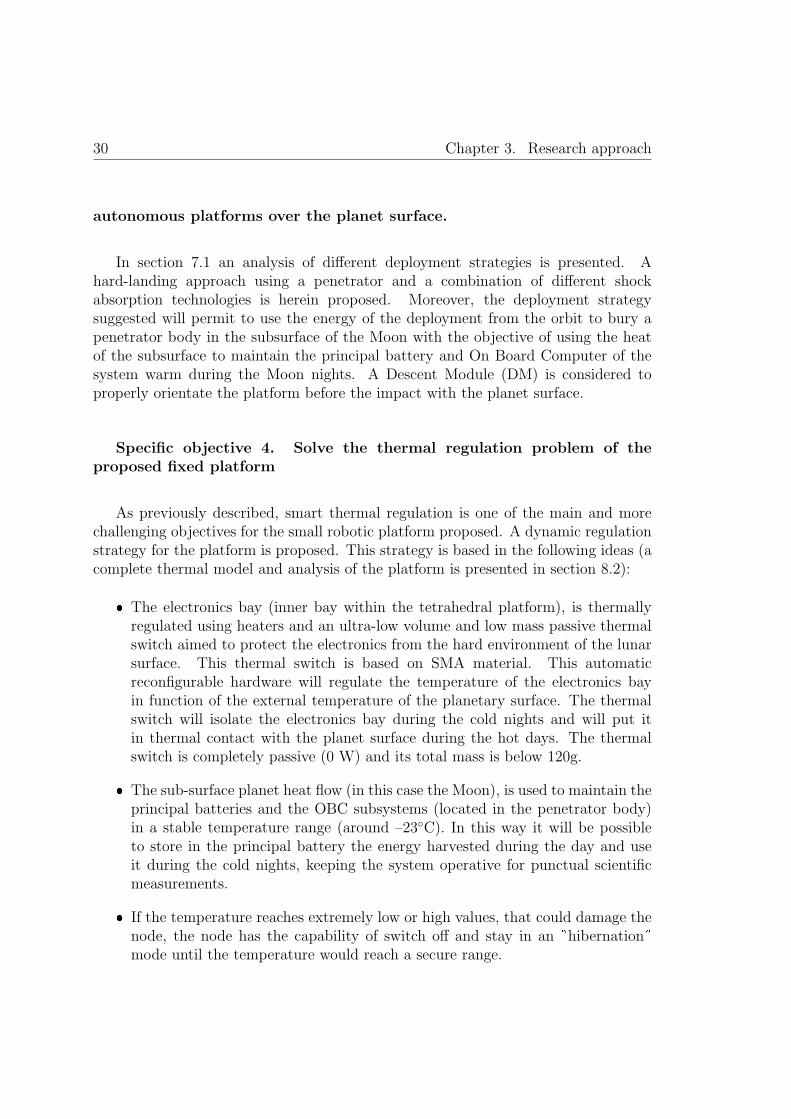
30 Chapter 3. Research approach
autonomous platforms over the planet surface.
In section 7.1 an analysis of different deployment strategies is presented. Ahard-landing approach using a penetrator and a combination of different shockabsorption technologies is herein proposed. Moreover, the deployment strategysuggested will permit to use the energy of the deployment from the orbit to bury apenetrator body in the subsurface of the Moon with the objective of using the heatof the subsurface to maintain the principal battery and On Board Computer of thesystem warm during the Moon nights. A Descent Module (DM) is considered toproperly orientate the platform before the impact with the planet surface.
Specific objective 4. Solve the thermal regulation problem of theproposed fixed platform
As previously described, smart thermal regulation is one of the main and morechallenging objectives for the small robotic platform proposed. A dynamic regulationstrategy for the platform is proposed. This strategy is based in the following ideas (acomplete thermal model and analysis of the platform is presented in section 8.2):
� The electronics bay (inner bay within the tetrahedral platform), is thermallyregulated using heaters and an ultra-low volume and low mass passive thermalswitch aimed to protect the electronics from the hard environment of the lunarsurface. This thermal switch is based on SMA material. This automaticreconfigurable hardware will regulate the temperature of the electronics bayin function of the external temperature of the planetary surface. The thermalswitch will isolate the electronics bay during the cold nights and will put itin thermal contact with the planet surface during the hot days. The thermalswitch is completely passive (0 W) and its total mass is below 120g.
� The sub-surface planet heat flow (in this case the Moon), is used to maintain theprincipal batteries and the OBC subsystems (located in the penetrator body)in a stable temperature range (around –23◦C). In this way it will be possibleto store in the principal battery the energy harvested during the day and useit during the cold nights, keeping the system operative for punctual scientificmeasurements.
� If the temperature reaches extremely low or high values, that could damage thenode, the node has the capability of switch off and stay in an �hibernation�mode until the temperature would reach a secure range.

3.2. General outline of the proposed solution 31
� The structure of the node has the capability of work as a radiator during the dayin order to reduce its temperature increase due to the incident solar radiation.
Specific objective 5. Innovative concepts for energy harvesting over theplanetary surface
Energy harvesting from the planet surface is mandatory for long term missionsif RTGs are not used. Photovoltaic, thermal and thermoelectric energy harvestingtechniques are proposed. The solar energy will be harvested using solar panels.
The platforms, released from the Descent Module at a certain altitude of theplanet surface, will penetrate in the sub-surface of the planet using the missile shapedpenetrator proposed in chapter 7. It is important to highlight the advantages of thisstrategy, that does not use the energy stored in the batteries to dig into the planetsurface, and uses the kinetic energy of the robotic platform during the deployment.As explained in detail in chapter 9, the temperature difference between the planetsurface and the subsurface will be used to:
� Harvest thermal energy to maintain the penetrator body above –25◦C, ensuringin this way the operability of the OBC and principal batteries continuously (evenduring the cold nights).
� Use the temperature difference between the surface and the subsurface togenerate electrical power using a new and innovative Thermoelectric Generator(TEG).
Specific objective 6. Definition of a high level control architecture forthe autonomous robotic platform.
A complete custom control architecture is proposed for the robotic platform.Chapter 10 introduces the control architecture conceived, based in an hybridarchitecture. Thermal, irradiance, power consumption and power generationmathematical models are also developed as required inputs for the platform control.
3.2.1 The Moon: selection as target scenario for technologiesdemonstration
Although the platform concept proposed can be potentially used in different outerspace rocky bodies, it is required the selection of a specific target with the objective

32 Chapter 3. Research approach
of stablish the boundary conditions that shall be used during the calculations for thedesign and the definition of the demonstration tests and simulations.
The selected scenario is the Moon. Lunar surface exploration has been selected astarget scenario due to its excellent conditions for the demonstration of the technologiesdeveloped under this thesis. The main considerations that justify this selection arethe following:
� Environmental conditions. The environmental conditions of the Moon generatea representative scenario where it is possible to find most of the environmentalconditions that could be found in other extraterrestrial bodies:
– Radiation. Without a magnetosphere or an atmosphere to protect theMoon, the lunar surface is exposed to the space radiation including CosmicGalactic Rays, solar events and space radiation as described in section 6.3.
– Temperature. The Moon presents a wide range of extreme thermalconditions as described in section 6.5.
– Illumination. At mid latitudes the Moon has a long diurnal cycle(approximately 28 days long, been 14 days of day and 14 days of nightat mid latitudes). This cycle varies in function of the latitude (refer tosection 6.4 for details of illumination conditions over the lunar surface).
– Atmospheric pressure. The Moon surface presents near vacuum conditions.
– Gravity. Low gravity conditions are of great interest for scientificexperiments.
– Dust. The dust, as explained in section 1.4, is a harmful environmentalphenomenon that can be found in most of the outer space bodies.
� Knowledge, proximity and infrastructure ( [Marshall et al., 2001]). The Moon isthe closest and most accessible extraterrestrial body with launch opportunitiesavailable during all the yearlong. It provides options for low cost missions ofhigh scientific and technological value. As the Moon is only a few days away byspacecraft, missions can be sent to the Moon, operated from either the Earthor the Moon, and completed within a week. Additionally we have to considerthat orbiting spacecrafts for space link between the surface platforms and theEarth are already available or can be deployed at a low cost compared withother extraterrestrial objectives as Mars.
� SWIPE project opportunity for demonstration technologies. As described insection 3.1.1, SWIPE project targets the Moon as main objective. As thisthesis takes the opportunity to test several of the technologies herein proposedand developed under the SWIPE project, the selection of the Moon as scenariomission is of critical importance.

Chapter 4
State of the Art
33

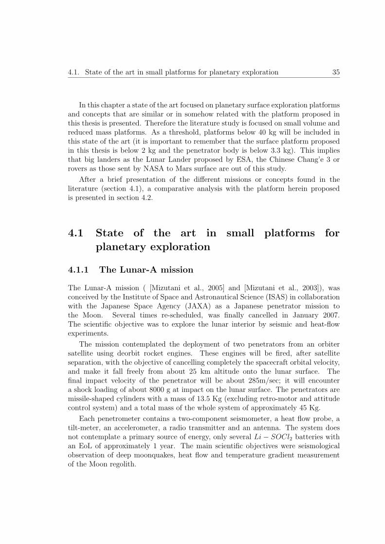
4.1. State of the art in small platforms for planetary exploration 35
In this chapter a state of the art focused on planetary surface exploration platformsand concepts that are similar or in somehow related with the platform proposed inthis thesis is presented. Therefore the literature study is focused on small volume andreduced mass platforms. As a threshold, platforms below 40 kg will be included inthis state of the art (it is important to remember that the surface platform proposedin this thesis is below 2 kg and the penetrator body is below 3.3 kg). This impliesthat big landers as the Lunar Lander proposed by ESA, the Chinese Chang’e 3 orrovers as those sent by NASA to Mars surface are out of this study.
After a brief presentation of the different missions or concepts found in theliterature (section 4.1), a comparative analysis with the platform herein proposedis presented in section 4.2.
4.1 State of the art in small platforms for
planetary exploration
4.1.1 The Lunar-A mission
The Lunar-A mission ( [Mizutani et al., 2005] and [Mizutani et al., 2003]), wasconceived by the Institute of Space and Astronautical Science (ISAS) in collaborationwith the Japanese Space Agency (JAXA) as a Japanese penetrator mission tothe Moon. Several times re-scheduled, was finally cancelled in January 2007.The scientific objective was to explore the lunar interior by seismic and heat-flowexperiments.
The mission contemplated the deployment of two penetrators from an orbitersatellite using deorbit rocket engines. These engines will be fired, after satelliteseparation, with the objective of cancelling completely the spacecraft orbital velocity,and make it fall freely from about 25 km altitude onto the lunar surface. Thefinal impact velocity of the penetrator will be about 285m/sec; it will encountera shock loading of about 8000 g at impact on the lunar surface. The penetrators aremissile-shaped cylinders with a mass of 13.5 Kg (excluding retro-motor and attitudecontrol system) and a total mass of the whole system of approximately 45 Kg.
Each penetrometer contains a two-component seismometer, a heat flow probe, atilt-meter, an accelerometer, a radio transmitter and an antenna. The system doesnot contemplate a primary source of energy, only several Li− SOCl2 batteries withan EoL of approximately 1 year. The main scientific objectives were seismologicalobservation of deep moonquakes, heat flow and temperature gradient measurementof the Moon regolith.
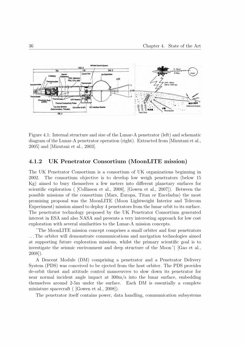
36 Chapter 4. State of the Art
Figure 4.1: Internal structure and size of the Lunar-A penetrator (left) and schematicdiagram of the Lunar-A penetrator operation (right). Extracted from [Mizutani et al.,2005] and [Mizutani et al., 2003].
4.1.2 UK Penetrator Consortium (MoonLITE mission)
The UK Penetrator Consortium is a consortium of UK organizations beginning in2002. The consortium objective is to develop low weigh penetrators (below 15Kg) aimed to bury themselves a few meters into different planetary surfaces forscientific exploration ( [Collinson et al., 2008], [Gowen et al., 2007]). Between thepossible missions of the consortium (Mars, Europa, Titan or Enceladus) the mostpromising proposal was the MoonLITE (Moon Lightweight Interior and TelecomExperiment) mission aimed to deploy 4 penetrators from the lunar orbit to its surface.The penetrator technology proposed by the UK Penetrator Consortium generatedinterest in ESA and also NASA and presents a very interesting approach for low costexploration with several similarities to the Lunar-A mission concepts.
The MoonLITE mission concept comprises a small orbiter and four penetrators. . . The orbiter will demonstrate communications and navigation technologies aimedat supporting future exploration missions, whilst the primary scientific goal is toinvestigate the seismic environment and deep structure of the Moon ( [Gao et al.,2008]).
A Descent Module (DM) comprising a penetrator and a Penetrator DeliverySystem (PDS) was conceived to be ejected from the host orbiter. The PDS providesde-orbit thrust and attitude control manoeuvres to slow down its penetrator fornear normal incident angle impact at 300m/s into the lunar surface, embeddingthemselves around 2-5m under the surface. Each DM is essentially a completeminiature spacecraft ( [Gowen et al., 2008]).
The penetrator itself contains power, data handling, communication subsystems
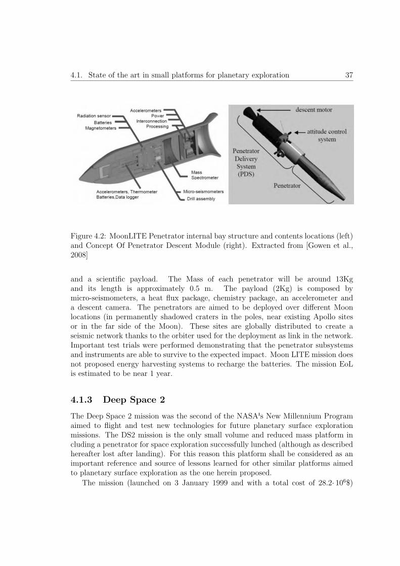
4.1. State of the art in small platforms for planetary exploration 37
Figure 4.2: MoonLITE Penetrator internal bay structure and contents locations (left)and Concept Of Penetrator Descent Module (right). Extracted from [Gowen et al.,2008]
and a scientific payload. The Mass of each penetrator will be around 13Kgand its length is approximately 0.5 m. The payload (2Kg) is composed bymicro-seismometers, a heat flux package, chemistry package, an accelerometer anda descent camera. The penetrators are aimed to be deployed over different Moonlocations (in permanently shadowed craters in the poles, near existing Apollo sitesor in the far side of the Moon). These sites are globally distributed to create aseismic network thanks to the orbiter used for the deployment as link in the network.Important test trials were performed demonstrating that the penetrator subsystemsand instruments are able to survive to the expected impact. Moon LITE mission doesnot proposed energy harvesting systems to recharge the batteries. The mission EoLis estimated to be near 1 year.
4.1.3 Deep Space 2
The Deep Space 2 mission was the second of the NASA s New Millennium Programaimed to flight and test new technologies for future planetary surface explorationmissions. The DS2 mission is the only small volume and reduced mass platform including a penetrator for space exploration successfully lunched (although as describedhereafter lost after landing). For this reason this platform shall be considered as animportant reference and source of lessons learned for other similar platforms aimedto planetary surface exploration as the one herein proposed.
The mission (launched on 3 January 1999 and with a total cost of 28.2· 106$)
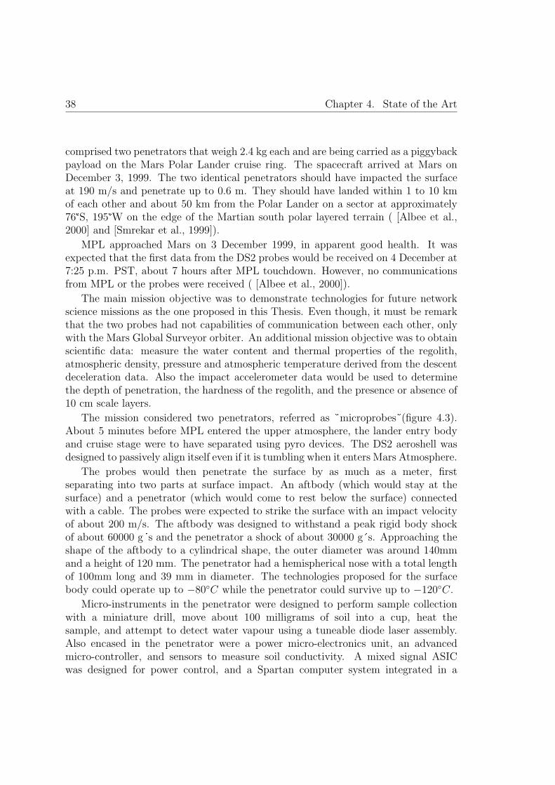
38 Chapter 4. State of the Art
comprised two penetrators that weigh 2.4 kg each and are being carried as a piggybackpayload on the Mars Polar Lander cruise ring. The spacecraft arrived at Mars onDecember 3, 1999. The two identical penetrators should have impacted the surfaceat 190 m/s and penetrate up to 0.6 m. They should have landed within 1 to 10 kmof each other and about 50 km from the Polar Lander on a sector at approximately76�S, 195�W on the edge of the Martian south polar layered terrain ( [Albee et al.,2000] and [Smrekar et al., 1999]).
MPL approached Mars on 3 December 1999, in apparent good health. It wasexpected that the first data from the DS2 probes would be received on 4 December at7:25 p.m. PST, about 7 hours after MPL touchdown. However, no communicationsfrom MPL or the probes were received ( [Albee et al., 2000]).
The main mission objective was to demonstrate technologies for future networkscience missions as the one proposed in this Thesis. Even though, it must be remarkthat the two probes had not capabilities of communication between each other, onlywith the Mars Global Surveyor orbiter. An additional mission objective was to obtainscientific data: measure the water content and thermal properties of the regolith,atmospheric density, pressure and atmospheric temperature derived from the descentdeceleration data. Also the impact accelerometer data would be used to determinethe depth of penetration, the hardness of the regolith, and the presence or absence of10 cm scale layers.
The mission considered two penetrators, referred as �microprobes�(figure 4.3).About 5 minutes before MPL entered the upper atmosphere, the lander entry bodyand cruise stage were to have separated using pyro devices. The DS2 aeroshell wasdesigned to passively align itself even if it is tumbling when it enters Mars Atmosphere.
The probes would then penetrate the surface by as much as a meter, firstseparating into two parts at surface impact. An aftbody (which would stay at thesurface) and a penetrator (which would come to rest below the surface) connectedwith a cable. The probes were expected to strike the surface with an impact velocityof about 200 m/s. The aftbody was designed to withstand a peak rigid body shockof about 60000 g�s and the penetrator a shock of about 30000 g�s. Approaching theshape of the aftbody to a cylindrical shape, the outer diameter was around 140mmand a height of 120 mm. The penetrator had a hemispherical nose with a total lengthof 100mm long and 39 mm in diameter. The technologies proposed for the surfacebody could operate up to −80◦C while the penetrator could survive up to −120◦C.
Micro-instruments in the penetrator were designed to perform sample collectionwith a miniature drill, move about 100 milligrams of soil into a cup, heat thesample, and attempt to detect water vapour using a tuneable diode laser assembly.Also encased in the penetrator were a power micro-electronics unit, an advancedmicro-controller, and sensors to measure soil conductivity. A mixed signal ASICwas designed for power control, and a Spartan computer system integrated in a
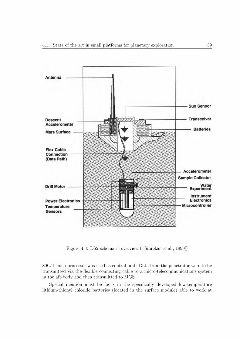
4.1. State of the art in small platforms for planetary exploration 39
Figure 4.3: DS2 schematic overview ( [Smrekar et al., 1999])
80C51 microprocessor was used as control unit. Data from the penetrator were to betransmitted via the flexible connecting cable to a micro-telecommunications systemin the aft-body and then transmitted to MGS.
Special mention must be focus in the specifically developed low-temperaturelithium-thionyl chloride batteries (located in the surface module) able to work at
40 Chapter 4. State of the Art
temperatures as low as −80◦C. The probes used 2 batteries with a total mass of 80grams (40 g per battery). Batteries were the unique source of power, for this reasononce the batteries were depleted the mission would end, approximately after one ortwo Martian days (no harvesting technologies were proposed in this mission).
Despite the low mass and volume of the DS2 probes, a complex experiment wasincluded for soil water content measurement. A micromotor would drive a small drillat the side of the penetrator. The soil sample would be deposited into a heater cup(sealed with a pyro system). The soil would be then heated, driving any water vapourinto the analysis chamber. If water was present, it would be detected by measuringthe difference in light intensity of a laser shining through the vapour. The tuneablediode laser was set so that its light is at the point in the spectrum where water absorbslight.
The penetrator system development required a complex test program ( [Lorenzet al., 2000]). The probe�s bullet-like forebody is designed with a half circle nose(tungsten) to ensure penetration over a wide range of entry conditions.
4.1.4 Luna-Glob
The Russian Luna-Glob mission was conceived during the 90s with the objective ofstudying the origin of the Earth-Moon system and the investigation of the chemicalcomposition and physical characteristics of the lunar materials at the landing siteincluding the detection of water traces. The mission was cancelled and rebirth severaltimes due to funding problems mainly, also it was redefined several times. From thebeginning, high-speed penetrators were considered. Around 2010 it was decided toabandon the development of penetrators for the Luna-Glob mission. Between thereasons to abandon the penetrator technology were that hard-landing and semi-hardlanding approach considered were found too risky for the mission (first lunar Russianmission to the Moon in decades) and there were problems developing the thrustersinitially considered for the semi-hard landing (Russian Space Web, [WB1]).
For the analysis of the state of the art herein presented it is considered theoriginal mission scenario as described in [Galimov, 2005] and [Surkov et al., 1999],and specifically the high speed small penetrators initially proposed. The originalLunar-Glob mission contemplated four different systems:
� 10 small high-speed penetrators (hard-landing).
� 2 penetrators-landers (semi-hard-landing). Focused in complex scientificexperiments including broadband seismometery.
� Polar station consisting in a landing module, braking engine and inflated shockabsorber powered by a RTG.

4.1. State of the art in small platforms for planetary exploration 41
Orbiter. The remaining orbiter of the spacecraft (after separation of the landers)would be used as communication link between the landers and the Earth andalso it would be used for global cartography of the Moon.
The 10 small high-speed penetrators would be deployed in two circles (refer tofigure 4.4), creating a virtual seismic antenna on the surface of the Moon. Thisexperiment based on the concept of small aperture seismic array was proposed byKhavroshkin and other seismologists at the Institute of the Earth Physics in Moscow,with the objective of studying the internal composition and history of the Earth’snatural satellite. The high speed penetrators are assembled into a ring cassette. Thepenetrator cassette is provided with a battery, solid-fuel engines and a control unit.The seismic array is best deployed in an area having low seismicity and thick regolithlayer.
Figure 4.4: Schematic of the deployment of high speed penetrator extracted from[Galimov, 2005] (left) and scheme of the high speed penetrator buried under theMoon surface extracted from [Surkov et al., 1999]
The information available in the literature about the small penetrators is veryconfusing and with important gaps as the small penetrator dimensions, mass anddetail description.
4.1.5 Met-Net
MetNet Mars Mission ( [Harri et al., 2007]), is a mission proposal aimed to deployan in situ observational network and orbital platform to investigate the Martianenvironment.

42 Chapter 4. State of the Art
The scope of the MetNet Mission is to deploy MetNet Landers on the Martiansurface by using inflatable descent system structures accompanied by an atmosphericsounder and data relay onboard the MetNet Orbiter, which is based on ESA MarsExpress satellite platform. The MetNet Landers are attached on the three sides ofthe satellite and are deployed to Mars separately, a few weeks prior to the arrivalto Mars. The MetNet Orbiter will perform continuous atmospheric soundings thuscomplementing the accurate in situ observations at the Martian ground produced bythe MetNet observation network, as well as the orbiter will serve as the primary datarelay between the MetNet Landers and the Earth.
The MNLs are equipped with a science payload focused on the atmosphericscience of Mars. Detailed characterization of the Martian atmospheric circulationpatterns, boundary layer phenomena, and climatological cycles, as well as interiorinvestigations, require simultaneous in-situ meteorological, seismic and magneticmeasurements from networks of stations on the Martian surface.
The MetNet Mars Mission proposal was implemented in collaboration with ESA,FMI, LA, IKI and the payload providing science teams (INTA, UC3M and UPMamong others).
The payload of the two MNL precursor models includes the following instruments( [Harri et al., 2015]):
� Atmospheric instruments: MetBaro Pressure device, MetHumi Humidity deviceand MetTemp Temperature sensors.
� Optical devices: PanCam Panoramic, MetSIS Solar irradiance sensor withOWLS optical wireless system for data transfer and DS Dust sensor.
Among the science teams that developed the payload for the MetNet Landers, theauthor of this thesis participated in the Arquimea�s team that subcontracted by theUniversity Carlos III de Madrid developed a Dust Sensor (Figure 4.5 right), aimed tocharacterize the suspended dust in the Martian atmosphere, Alvarez 2011.
The initial landing sites are selected in a latitude range of �30 degrees and atlow altitudes, thereby allowing the use of only solar panels as energy source andavoiding the political problems of including radioactive generators into the Lander.For high-latitude missions radioactive heaters will be necessary to make the systemssurvive the Martian winter ( [Harri et al., 2012]). MNL flexible solar panels providesa total of approximately 0.7-0.8 W of electric power during the daylight time. As theprovided power output is insufficient to operate all instruments simultaneously, theyare activated sequentially according to a specially designed cyclogram table whichadapts itself to the different environmental constraints.
The total mass of the entry vehicle is 22.2 Kg (4Kg of payload). Currentlyone complete flight unit has been manufactured and tested to acceptance levels atLavochkin and the mission is waiting for a flight opportunity.
4.1. State of the art in small platforms for planetary exploration 43
Figure 4.5: MetNet Lander section view extracted from WB5 (left). Dust SensorFlight Model (right) courtesy of Arquimea Ingenierıa S.L.U and University Carlos IIIof Madrid.
4.1.6 RF-WIPE
The RF-WIPE ( [Sanz et al., 2013]), was a study supported by ESA underGSP contract and developed by GMV acting as prime contractor in partnershipwith SUPSI, (Scuola Universitaria Professionale della Svizzera Italiana) and UPM,(Universidad Politecnica de Madrid). This study was focused on analysing the sensornetworks for planetary exploration to identify and characterize all possible explorationscenarios suitable to exploit the capabilities of sensors network technologies based inthe 802.15.4 protocol standard. Although the study does not specify hardware detailsof the space compatible systems to be used for the proposedWSN, the study presents arobotic launcher device ( [Sanz et al., 2010]), developed using commercial componentsand implemented to deploy the nodes that compound the WSN. The study analysesdifferent deployment techniques and network configurations. Even though this studyis not focused in the planetary exploration platform itself, it provides a detail study ofthe feasibility of use WSN for space exploration and also demonstrate the interest ofthe Space Agencies (in this case ESA), in WSN as an alternative for space exploration.
4.1.7 Hopping robots
The term hopping robots refers to robotic systems with the capability of move usingdifferent jumping methods that permits them to avoid obstacles and move through

44 Chapter 4. State of the Art
the terrain. Several of these hopping robots have been proposed for planetary surfaceexploration. Currently, Hayabusa 2 mission shipped two jumping robots that are intheir way to meet an asteroid in the following two years.
These hopping robots are miniature mobile robots (few kg or even below the kg),with scientific payload used for distributing sensing. Most of the proposed conceptsmake use of WSN. Although the proposed platform in this thesis is a fixed platform,these hopping robots are presented and analysed in this state of the art since theyshare several attributes similar to the technologies herein proposed: low mass, lowpower consumption and distributing sensing using WSN. In the literature can befound several proposals of hopping robots for planetary surface exploration, belowsome of the most similar to the concept proposed in this thesis are presented forcomparative purposes with the technologies herein studied.
Canadian Space Agency hopping robot
The Canadian Space Agency ( [Montminy et al., 2008]) developed a hopping robotprototype for Mars surface exploration based on regular tetrahedron geometry and aSMA actuator for jumping. The tetrahedron provides robustness to recover from thelanding after the jump in any possible configuration.
Figure 4.6: Canadian Space Agencyhopping mechanism (extracted from[Montminy et al., 2008]
One of the main technologies proposed in this platform, that makes the concept avery promising alternative for space exploration, is the SMA actuator. This actuatoruses the variations of temperature on the Martian surface as a source of energy, thus

4.1. State of the art in small platforms for planetary exploration 45
reducing the dependence of stored energy for locomotion. After the jump the robotdeploys its petals that roll the robot to its vertical configuration. The petals arecovered with solar panels in order to provide energy to the on-board subsystems. Asingle SMA based actuator is used for the jumping, petals deployment and retractingof the mechanism to perform the following jump. This locomotion mechanism is lowpower (0W actually), low mass and permits to jump (inaccurately) 3 meters per solover the Mars surface. The total lander mass was conceived to be less than 2 Kgwith 250 g of mass for the payload.
MIT hopping micro-robots
The Massachusetts Institute of Technology (MIT) supported by the NASAInstitute for Advanced Concepts ( [Dubowsky et al., 2006]), proposed a missionconcept based on the deployment of a large number of small jumping sphericalmobile robots. The robots would be deployed from orbit using, one or several, softlanding modules with the capability of deploy tens to hundreds of these units. Theproposed spherical robots (10 cm in diameter and about 100 grams) could be ableof generate mobile WSN and collaborate with surrounding nodes. These robotswould be equipped with a suite of miniaturized sensors as imagers, spectrometersand chemical analysis sensors. The locomotion system is based on a �foot�composedof a dielectric elastomer actuator powered by hydrogen/oxygen fuel cells. The slowrate of power generation charges slowly the dielectric elastomer actuator and releasesthe energy during the jump. A very efficient fuel storage concept based on ProtonExchange Membrane (PEM) fuel cells powered by stored, on-demand hydrogen inthe form of metal hydrides is proposed as main source of power ( [Thangavelauthamet al., 2012]). This robot does not include harvesting energy concepts. A passivethermal control based on radiators and intelligent power control is proposed forthermal regulation. The concept is based on several technologies not availableat the moment of the proposal that were expected to be developed in the nearfuture. Thus a prototype of the complete platform was not developed. Even theconcept is very interesting, the mass estimation is really optimistic and basedon technologies developments which feasibility have to been proven (e.g. spacecompatible miniaturized sensors and subsystems, fuel cells of low mass and volumeand high power output).
CalTech hopping robot
The California Institute of Technology in collaboration with the Universita di

46 Chapter 4. State of the Art
Verona, developed several prototypes of small jumping robots ( [Burdick and Fiorini,2003]). The authors define the mobile platform proposed as �minimalist jumpingrobots�with the capability of exploring planetary surface large areas, coordinatingtheir motions to collectively gather distributed scientific data. The work wasfocused in the locomotion system including mechanical methods for locomotion,attitude control ( [Tammepold et al., 2011]) and localization. The 1st generationprototype was a football shaped device capable of short jumps, but stimulated muchof the results of successive developments. The 2nd prototype was a minimalisticdevice powered by a single motor, capable of about 3 m jumps and equipped withself-righting capabilities. The 3rd generation prototype is equipped with wheels andis capable of long, but coarse, jumps using the hopping mechanism, and short, precisemotion using wheels. The proposed work does not detail the mission concept or theoverall platform design, although it is an important step onwards the demonstrationof feasible jumping systems for space exploration.
HAYABUSA2 (mission)
Japan (JAXA) launched the second sample return spacecraft �Hayabusa2�to theNear-Earth asteroid �1999JU3�in December 2014. Hayabusa2 is a scientific-drivenmission to retrieve some fragments from a C-type asteroid ( [Yoshimitsu et al., 1999]).The predecessor spacecraft �Hayabusa�made a great success when it returned to theEarth in June 2010 with a capsule containing some particles obtained from the S-typeasteroid �Itokawa�( [Kawaguchi et al., 2010]).
Hayabusa2 mission contemplates the inclusion of three hopping robots to explorethe asteroid surface:
� Two twin hopping robots developed by JAXA: MINERVAII
� Hopping robot developed by the German Aerospace Centre (DLR) and theCentre National d’Etudes Spatiales (CNES): MASCOT
Both hopping robots are described in the following paragraphs.
MINERVAII
Minerva II payload consists of two rover containers, a relay module and an antennato communicate with the rovers. Three rovers are included in the two containers(figure 4.7). Two of the three rovers look like a cylinder and have a mass ofapproximately 1.1 kg each one ( [Kubota and Tomiki, 0015]). Each rover has installeda different set of sensors. The rovers are simultaneously ejected when the spacecraft
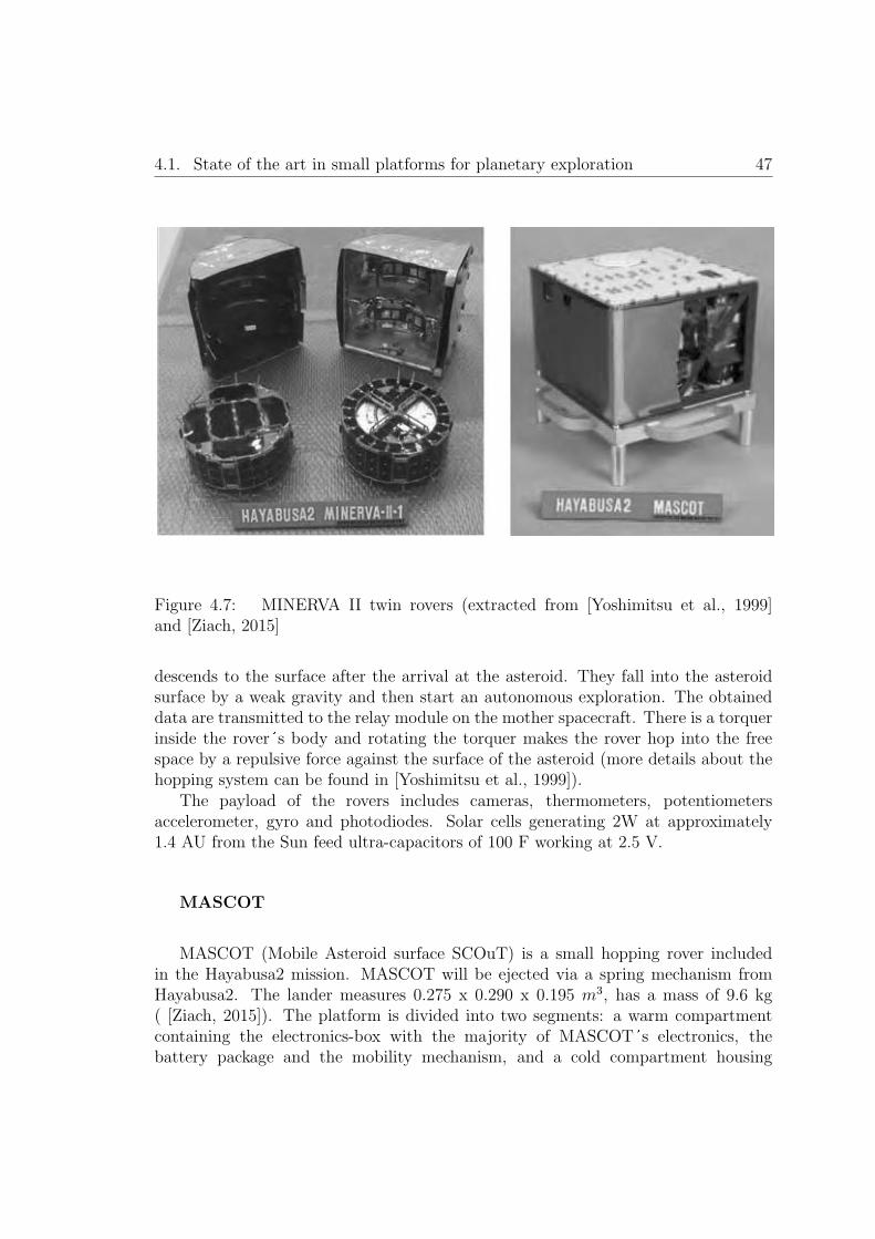
4.1. State of the art in small platforms for planetary exploration 47
Figure 4.7: MINERVA II twin rovers (extracted from [Yoshimitsu et al., 1999]and [Ziach, 2015]
descends to the surface after the arrival at the asteroid. They fall into the asteroidsurface by a weak gravity and then start an autonomous exploration. The obtaineddata are transmitted to the relay module on the mother spacecraft. There is a torquerinside the rover s body and rotating the torquer makes the rover hop into the freespace by a repulsive force against the surface of the asteroid (more details about thehopping system can be found in [Yoshimitsu et al., 1999]).
The payload of the rovers includes cameras, thermometers, potentiometersaccelerometer, gyro and photodiodes. Solar cells generating 2W at approximately1.4 AU from the Sun feed ultra-capacitors of 100 F working at 2.5 V.
MASCOT
MASCOT (Mobile Asteroid surface SCOuT) is a small hopping rover includedin the Hayabusa2 mission. MASCOT will be ejected via a spring mechanism fromHayabusa2. The lander measures 0.275 x 0.290 x 0.195 m3, has a mass of 9.6 kg( [Ziach, 2015]). The platform is divided into two segments: a warm compartmentcontaining the electronics-box with the majority of MASCOT s electronics, thebattery package and the mobility mechanism, and a cold compartment housing

48 Chapter 4. State of the Art
the payload. The payload includes a spectrometer, a camera, a radiometer and amagnetometer. MASCOT�s telemetry will be relayed to ground via Hayabusa2. Amobility mechanism allows MASCOT to hop across the surface at a distance of upto 220 m.
The platform contains only a primary battery (9 LSH-20 cells in a 3s3pconfiguration). The expected lifetime of MASCOT is limited by the energy stored inits battery, in the order of 10 hours.
4.2 State of the art analysis
The following table presents a brief comparative of the different missions and conceptsof the literature including the platform proposed in this thesis.

4.2. State of the art analysis 49
Mission/
Conce
pt
Mass
Deployment
Scientific
Payload
Area
covera
ge
Energ
yso
urce
Lunar-A
(mission)
45Kg
(13.5Kg
excluding
deployment
system
)
Penetration
/hardlanding
-Seism
ometer
-Heatflow
Low
coverage
Few
squaremeters
per
penetrator
(withou
tcommunication
capab
ilitiesbetween
penetrators)
Li-SOCl2
batteries
(1year
EoL
)Noharvesting
MoonLIT
E(m
ission)
36kg:
23kgpropulsion
13kgpenetrator
(science
payload
2kg)
Penetration
/hardlanding
-Micro-seism
ometer
-Heatflow
package
-Accelerom
eter
-Thermal
sensors
-Descentcamera
-Chem
istrypackage
-Rad
iation
sensor
Low
coverage
Few
squaremeters
per
penetrator
(4penetrators
withou
tcommunication
capab
ilitiesbetween
them
directly)
Batteries
(1year
EoL
)Noharvesting
Deep
Space
2(m
ission)
3,107Kg
(0,7Kgaeroshell,
1,737K
gsurface
platform
and
0,67Kg
penetrator)
Penetration
/hardlanding
-Subsurfacesoil
sampling/water
-Soilconductivity
-Tem
perature
-Sunsensor
-atm
ospheric
pressure
-accelerom
eter
Low
coverage
Few
squaremeters
per
penetrator
(withou
tcommunication
capab
ilities
betweenpenetrators)
Ultra-low
temperature
lithium
battery
Lifetim
e1/2
Martian
days
Noharvesting
Luna-G
lob
(mission)
Not
specified
High-speed
penetration
(hardlanding)
-Smallap
erture
seismic
array
Low
-medium
coverage
Battery
and
solid-fuel
engines
MetN
et
(mission)
22.2
Kg
(4Kgpayload
)
Penetration
/Sem
i-hard
landing
-Pressure
sensor
-Humiditysensor
-Tem
perature
sensors
-Pan
oram
iccamera
-Solar
irradiance
-DSDust
sensor
Large-m
edium
coverage
Coveragedep
ending
onthenumber
ofMNLsdeployed
Flexible
solar
pan
elsat
mid
latitudes
RTG
forpolar
region
s
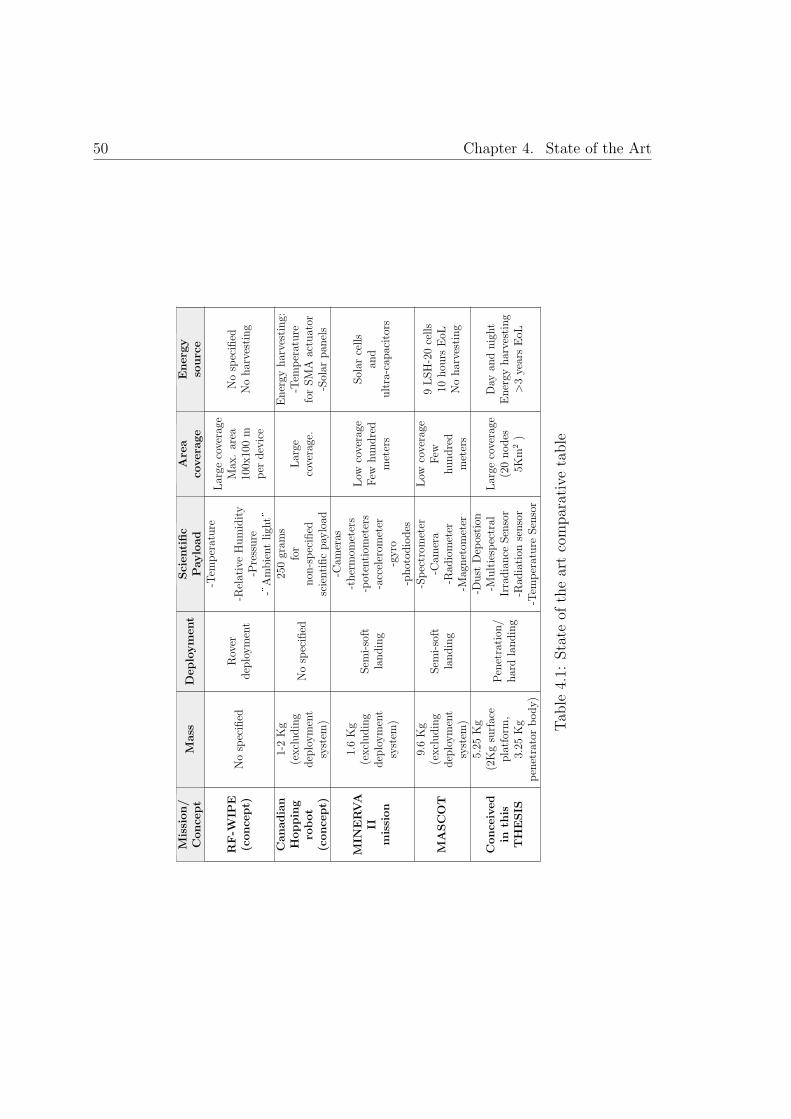
50 Chapter 4. State of the Art
Mission/
Conce
pt
Mass
Deployment
Scientific
Payload
Area
covera
ge
Energ
yso
urce
RF-W
IPE
(conce
pt)
Nospecified
Ro ver
deployment
-Tem
perature
-RelativeHumidity
-Pressure
-�Ambientligh
t�
Large
coverage
Max
.area
100x
100m
per
device
Nospecified
Noharvesting
Canadian
Hopping
robot
(conce
pt)
1-2Kg
(excluding
deployment
system
)
Nospecified
250gram
sfor
non
-specified
scientificpayload
Large
coverage.
Energy
harvesting:
-Tem
perature
forSMA
actuator
-Solar
pan
els
MIN
ERVA
IImission
1.6Kg
(excluding
deployment
system
)
Sem
i-soft
landing
-Cam
eras
-thermom
eters
-potentiom
eters
-accelerom
eter
-gyro
-photodiodes
Lo w
coverage
Few
hundred
meters
Solar
cells
and
ultra-cap
acitors
MASCOT
9.6Kg
(excluding
deployment
system
)
Sem
i-soft
landing
-Spectrom
eter
-Cam
era
-Rad
iometer
-Magnetom
eter
Lo w
coverage
Few
hundred
meters
9LSH-20cells
10hou
rsEoL
Noharvesting
Conce
ived
inth
isTHESIS
5.25
Kg
(2Kgsurface
platform,
3.25
Kg
penetratorbody)
Penetration
/hardlanding
-Dust
Dep
ostion
-Multiespectral
Irradiance
Sensor
-Rad
iation
sensor
-Tem
perature
Sensor
Large
coverage
(20nodes
5Km
2)
Day
andnight
Energy
harvesting
>3yearsEoL
Tab
le4.1:
State
oftheartcomparativetable

4.2. State of the art analysis 51
The state of the art presents a large variety of very interesting concepts andmissions which represent a starting point with vast information of lessons learnedand different ways of solve similar problems. However, none of the developmentsfound in the literature solve certain key points presented in previous sections thatmotivates this thesis:
� Large mission life (years) using several energy harvesting systems (withoutRTGs), including energy harvesting during the cold planet nights.
� Effective solutions to the deployment system (even in vacuum conditions) inorder to obtain a low mass entry system that could survive hard landingdeceleration forces.
� Low cost development of several low mass platforms using available technologiesin the state of the art.
� High reliable platforms relaying in redundant or complement systems withoutincrease the total mission mass.
Analysing in detail the different concepts and missions we could directlydistinguish some of them that are in a low TRL stage (Call Tech hopping robots),present incomplete studies of the exploration platform conceived (RF WIPE or LunaGlob) or even are based in concepts which are not technologically available currently(MIT hopping robot).
In the other hand we can find mature concepts and missions based on technologieswith a large heritage or with high TRL:
� Even though the Lunar-A mission was cancelled, the knowledge and informationobtained during the years of research provide an important input for futuredevelopment of penetrators for space exploration. Particularly interesting isthe knowledge acquired by the development team during the penetrator tests.As drawbacks of the concept proposed, it can be outlined the lack of energyharvesting systems and the reduced payload considering the large mass of eachpenetrator.
� Certainly the MoonLITE mission presents a very valuable heritage includinginteresting approaches that shall be considered in future proposals ordevelopments. In this thesis, the Descent Module (DM) designed by theMoonLite team has been used as a reference for the DM proposed. Thefield tests campaigns realized, demonstrating the penetrator concept and highshock survival techniques, are of special interest. The lack of energy harvestingtechnologies and the elevated mass of the penetrator that reduce the number ofpenetrators to be deployed are specific drawbacks of this concept.

52 Chapter 4. State of the Art
� The Deep Space 2 mission is of main importance, in the state of the artpresented, as it is the only mission based on a similar concept of the one hereinproposed that has been launched. Even designed and launched in the latest 90s,the developed technologies as the ultra-low temperature batteries are currentlyvery interesting. The lessons learned and compiled in [Albee et al., 2000], shallbe carefully studied and considered for future missions. The lack of harvestingenergy systems with a very limited life (only 2 Martian days) and the need ofincluding reliable shock protection systems are two important drawbacks of thisconcept.
� MetNet mission is other mature concept developed and currently searchingfor a mission opportunity that demonstrates the potential of penetratortechnologies for planetary exploration. The concept, that initially contemplatedthe use of RTGs, changed to solar harvesting as primary source of powercertainly improving in this way the mission concept. Its payload andplatform distribution make it a very interesting approach for the meteorologicalcharacterization of a planet with atmosphere. Its large mass and theimpossibility of harvesting energy during de night are drawbacks of the conceptproposed. Also it must be considered that the deployment concept requires anatmosphere in order to reduce the entry velocity of the platform.
� The Canadian hopping robot concept presents a smart locomotion system basedon thermal energy harvesting. Even though the concept does not define amission or subsystems detail description (communications between nodes orrobots deployment over the planet surface) it introduces an innovative systemof locomotion for future developments.
� Hayabusa 2 jumping robots demonstrate that small platforms with a reducedpayload are very valuable for surface exploration of rocky bodies. Of particularinterest is the Minerva II robot, with capabilities of harvesting solar energy andstore it in ultra-capacitors for a limited time operation over the body surface.These systems are designed for semi-hard landing on a low gravity body, similarconcepts could not be used on larger planets with a higher gravity withoutincorporate shock protection systems. Also, the thermal design based on ashort day/night cycle is incompatible with the large day/night cycles of largerbodies.

Chapter 5
Self–powered and low mass fixedplatform
53


5.1. Platform configuration 55
5.1 Platform configuration
Reviewing the state of the art (chapter 4), we can distinguish two different platformsconcepts: (i) subsurface platforms (penetrators as those proposed by Moon-LITE orLunar–A missions) or (ii) surface platforms (as the RF–WIPE, Canadian or MIThopping robots). A more flexible approach is the one followed by the DeepSpace2or MetNet missions in which part of the platform is beneath the surface and theother part remains over the surface. In line with this mixed configuration, this thesisintroduces a new platform that exploits all the advantages of having a dual bodyplatform that were not fully exploited in previous concepts proposed: as a dynamicthermal regulation (chapter 8), energy harvesting (chapter 9), redundancy (section5.5), shock absorption (section 7.2.3) and cost reduction for the deployment of a largenumber of platforms (chapter 7).
As introduced, the conceived configuration is based in a two-body system asdepicted in figure 5.1 and 5.2:
� A tetrahedral platform that will remain over the planet surface, also referred inthe literature as aftbody. The design, development and testing of this platformare described in detail in this thesis. The tetrahedral platform contains allthe scientific payload and acquisition electronics, solar panels, communicationsystems, power module and auxiliary batteries. Section 5.2 describes in detailthe conceived configuration of this part of the proposed platform.
� A penetrator body that will enter into the planet subsurface. The penetrator issituated in the baseplate of the tetrahedral platform and it will separate fromthe surface body during the penetration in the planet sub-surface as described insection 7.2. The penetrator body will contain the On Board Computer (OBC),the principal batteries including the related power electronics and the umbilicalcable that interconects both bodies of the platform. Section 5.3 describes thepenetrator body concept.

56 Chapter 5. Self–powered and low mass fixed platform
Figure 5.1: Two-body platform prior to landing impact (external solar cell shockprotection material not shown)

5.1. Platform configuration 57
Figure 5.2: Platform deployed, tetrahedral body over the surface and penetrator bodyunderground (frontal solar panel and protective resin removed for inner subsystemsview)
58 Chapter 5. Self–powered and low mass fixed platform
5.2 Surface tetrahedral platform description
The surface platform designed is a regular tetrahedron with an envelope of 200x200mm of base and 200 mm of height (figure 5.2), with a total mass below 2000g. Theproposed system configuration considers deployable solar panels. When closed, thedeployable walls in form of petals protect the node from the environment duringtransportation and deployment (shock and dust contamination during deploymentby penetrator, refer to chapter 7). Once the platform is over the planet surface arelease mechanism based on a shape memory alloy pin-puller device ( [Nava et al.,2012]) is activated and the solar panels are deployed, allowing the exposure of thepayload sensors and inner solar panels to the lunar surface.
A light aluminum structure, forming the tetrahedron and providing stiffness tothe node, holds all the elements together. The structural material selected forthe tetrahedral platform is aluminum. Aluminum and its alloys are non-magneticmaterials with a good combination of high stiffness to density ratio, high ductility,high corrosion-resistance, excellent workability and availability at a low cost.Specifically, due to the high stress that the structure shall support during the platformdeployment, a 7075 aluminum alloy is selected.
The inner part of the tetrahedron includes a dust sealed electronics baydynamically regulated by an ultra-low volume and weight passive thermal switchto protect the electronics from the hard environment of the lunar surface. The innerbay includes the following elements: power subsystem, communication subsystem,auxiliary batteries and payload acquisition electronics (that includes a redundant OnBoard Computer as described in section 5.5).
5.2.1 Tetrahedron shape selection
The tetrahedron shape selection of the platform impacts directly in the nodeperformance and capabilities. The selected shape introduces specific and significantadvantages for the proposed concept of mission with minor drawbacks. Othersolutions were considered, as the pyramidal shape (four faces) or dice shape (cube).A comparative analysis between the different alternatives considered is presentedbelow. The spherical solution was discarded due to its incompatibility with themission concept: higher manufacturing costs and interface complexity with othersubsystems.
Mass and volume considerations.
Mass is one of the main design drivers. The tetrahedron shape permits to reduceconsiderably the mass and volume of the node maintaining its performance. The

5.2. Surface tetrahedral platform description 59
three faces of the tetrahedron can be used to place sensors or antennas maintainingapproximately a 360◦ coverage. Pyramidal configuration (four faces) or dice shape(five faces) will imply the addition of a fourth, and even a fifth face, involving moremass and volume and not providing an important advantage. Another faces willincrease the solid angle resolution of the sensors or antennas, although with a properdesign a fourth or a fifth face will not be necessary to maintain a nearly 360◦ coverage.
Mechanical and structural considerations.
With the objective of being compatible with a penetrator technology deployment,the structure of the platform shall be structurally robust. The most stable structureshall be considered, due to the high shock levels expected during the landing.Considering a basic structural analysis of the platform, with the objective to selectthe most stable structure shape, we can consider to analyze the number of externalreactions. The number of external reactions must be greater than the number ofequations available for the structure to remain in a static equilibrium. Thus, for thestructure to be stable, the following equation shall be satisfied:
m ≥ 2j −D (5.1)
Where parameter m represents the number of elements of the consideredstructure, j is the number of joints and D is the number of equations available forthe structure to remain in a static equilibrium. D value is three for two-dimensional(planar) structures and it is six for three–dimensional (non-coplanar) structures.Considering this, the most stable and resistant structure in 2–D is the one composedby triangles. The triangle shape, under an external force applied, will deform withresistance; the force will be distributed between the joints and beams of the trianglethat shall be designed to support the expected loads. Considering this basic analysis,the selection of a tetrahedron shape (composed of regular triangles) ensures themost simple and resistant structure. The pyramidal shape also satisfies equation 5.1.Although a pyramidal shape will reduce drastically the resistance of the structurecompared with the tetrahedron. The reasons are that the number of joints increasesas the number of beams connected to the upper node. And considering that jointswill be the points that will most suffer during the shock they are the most probablepoints of failure. Reduce the number of joints will reduce the probability of structuralfailure during the shock. Also it could be possible to use stronger and heavier jointsif its number is reduced, thus maintaining a low total mass of the structure.
Performance considerations.
60 Chapter 5. Self–powered and low mass fixed platform
The advantages of a platform with pyramidal or dice shapes with respect to atetrahedron shape are mainly of performance:
� Available area for solar panels. With up to six faces the available space for solarpanels is drastically enhance.
� Increase the solid angle resolution of the different elements. In this case, thepyramidal shape would have a better performance. Using an additional sensoror antenna it is possible to cover with major resolution a virtual field of viewof 360◦.
� The effective available volume inside the platform is highly increased in thepyramidal shape and the dice shape.
Node integration considerations
The low volume and mass obtained with the tetrahedral shape is directly inconflict with the integration complexity of the node. Because of the reduced space,integration complexity is increased (including mounting and harnessing connection).
Cost considerations
The inner space of the tetrahedron node and the faces are triangular shaped. Thisis an important drawback for the use of commercial PCBs, solar panels or batterieswhile they are usually available with a square form. The project philosophy foreseesthe deployment of hundreds of nodes, then it would be possible to manufacturecustom solar panels being a cost effective solution due to the large number of unitsto be produced.
Concluding, the tetrahedron shape of the platform will imply a more advantageousmass/volume relation maintaining the mechanical structure stability with an adequateperformance. From a performance point of view, without consider the structuralstability of the platform, the dice shape would be the best choice because this shapewould increase the effective available space inside the node and the area for solarenergy harvesting. This is one of the main reasons why the dice shape has beenselected for the majority of satellites lunched.
Because the main directive is the mass and structure stability (a heavier nodewould be incompatible with the deployment of an important number of nodes and aless robust structure will be destroyed during the hard landing) the tetrahedron hasbeen selected as the optimum shape for the proposed platform.

5.2. Surface tetrahedral platform description 61
5.2.2 Inner electronics bay
The inner electronics bay is one of the key elements of the proposed two-bodyplatform. The electronics bay contents the following critical subsystems:
� Scientific payload acquisition electronics. Described in section 6.5.4, controlsthe entire payload and performs an acquisition procedure when commanded bythe OBC. Also this subsystem includes an enhanced FPGA capable of work asredundant OBC in case of malfunction of the nominal OBC (section 5.5).
� Communication subsystem. This subsystem allows the platform tocommunicate with the rest of the nodes of the WSN and includes thead-hoc, energy-efficient network protocols required for an efficient, reliableand low-power consumption WSN. This subsystem is out of the scope of thisthesis. A description of this subsystem developed under the SWIPE project andcompatible for the platform herein proposed can be found in [Rodrigues et al.,2014], [Rodrigues et al., 2015] and [Oddi et al., 2014a].
� Power subsystem. This subsystem performs the node power regulation andindividually supplies power to the different subsystems of the platform. A highreliability design using high reliability components is required for this criticalsubsystem. A power regulation block is also included in the penetrator bodyaimed to control the charging and discharging of the principal batteries whenthe main power regulation block is not operative (lunar nights or failure).
� Auxiliary batteries. The auxiliary batteries permit to extend the nodeoperational time drastically. Even more, in case of a malfunction of the principalbatteries (located in the penetrator body) the auxiliary batteries will be able tomaintain the operation of the node. The batteries considered are rechargeablelithium-ion battery model VL 34570 ( [Saft, 2009]).
All these subsystems within the inner electronics bay are integrated in a lightaluminium rack and embedded in a special resin (refer to section 7.2.3). The onlyrelevant area in thermal contact between the inner bay and the external structureis located in its base, where a thermal switch is located to control the heat fluxinterchange between the inner electronics bay and the external structure.
The electronics bay will protect the electronics from the environmental constrains:
� Temperature: Thermally regulated by a thermal switch and active heaters, asexplained in chapter 8, the inner bay will increase the operational time of theelectronics subsystems. The resin that embedded all the subsystems helps tomaintain a uniform temperature between the subsystems included in the innerbay.

62 Chapter 5. Self–powered and low mass fixed platform
� Vibration and shock. The embedded elements inside the inner bay are protectedfrom the high shock and vibration during the deployment of the platform overthe planet surface as described in section 7.2.3.
� Dust: The dust could not affect the inner electronics bay subsystems. Theexternal structure including the solar panels and the resin avoid the dust toenter in contact with the electronics components.
5.2.3 Scientific payload distribution
The customized conceived low power consumption and low mass payload for Moonsurface exploration is summarized below. The detail design description of each sensoris described in chapter 6. It is important to remark that the scientific payload includedin each node can be customized. Each node platform can be configured with differentsets of instruments, thus increasing drastically the scientific objectives of the wholemission. Likewise, sensors in the penetrator body could be included if required.
� Three temperature probes. These probes are sharpening aluminum probes thatare located in the base of the surface platform near triangle corners (section6.5).
� Three multispectral irradiance sensors (each one including three sensors atvisible, IR and UV) placed with a separation of 120◦ for a total field of view of360◦ at the three faces of the tetrahedral platform (section 6.4).
� A radiation sensor based on a mixed signal ASIC that provides Total IonizingDose (TID) and Single Effect Upsets (SEUs) radiation monitoring. This ASIChas been designed using radiation-hardening techniques and it is located in oneof the deployable solar petals. Its location in the external corner permits toreduce the influence of the platform in the radiation measurement (section 6.3).
� A Dust Deposition Sensor (DDS) for measuring the Moon dust deposited bynatural means over its optical surface. This sensor is located on the top ofthe platform to reduce the influence of the rest of the platform elements in itsmeasurments (section 6.3).
The acquisition electronics for all the sensors is located in the thermal regulatedinner bay. A dedicated FPGA commanded by the OBC will be in charge of controllingall the platform sensors obtaining the different measurement when requested by theOBC.

5.2. Surface tetrahedral platform description 63
5.2.4 Solar panels deployment subsystem
The release mechanism used for the deployment of the solar panels is based on apin puller from the family of actuators based on SMA (Shape Memory Alloy) fromArquimea Ingenierıa S.L.U.
Pin Puller non-explosive release actuators are mechanical devices which functionis to retract a pin that is used to lock a system that has to be released or deployed foroperation. These release mechanisms are high reliability devices enhanced for spaceenvironment and commonly used in spacecraft for solar panels, antennas or payloadsdeployment. These release mechanisms incorporate redundant SMA trigger capableof independently activate the actuator. Pin Puller release mechanism is a low shocknon-explosive actuator; it is reusable and can be reset by hand with the help of a tool.The mechanism is reset by simply retract the pin. The selected pin puller model pullsdown its pin when actuated with a force not lower than 25N (figure 5.3). The totalmass of the pin puller is 60 grams.
Figure 5.3: 25 N pin puller basedon SMA
Considering that there are three panels to deploy, an auxiliary three–armmechanism releases the three panels using one pin puller. The three–arm auxiliarypiece locks the solar panels while it is engaged to the mechanical fixation pieces of thesolar panels. Once the pin puller is actuated the three–arm piece releases the solarpanels and permits their deployment. A spring placed in the hinge of the solar panelsprovides the required force for the deployment. An external end of stroke sensor isused to control the pin puller activation.
During the solar panels deployment some dust will be ejected as consequence ofthe impact of the solar panels over the non–compacted upper layer of dust of theMoon surface. With the objective of reducing the quantity of this ejected dust, thatafterwards could be deposited over the solar panels or over the optical subsystems,the solar panels hinge is situated 20 millimeters above the tetrahedron base. Withthis disposition, the area of the solar panels that will enter in contact with the planetsurface is reduced. This height of the hinge w.r.t the platform base is also of mainimportance to ensure an acceptable solar panels deployment. The base of the platformcould be introduced some centimeters in the lunar soil during the landing. The height

64 Chapter 5. Self–powered and low mass fixed platform
of the solar panels hinge could be increased or reduced in function of the soil conditionsof the landing target.
5.3 Penetrator body description
The penetrator body part is 300 mm in height, 100 mm in diameter with the shapeof a ballistic missile. The penetrator is attached to the baseplate of the tetrahedralplatform and its total mass is below 3450 grams. The mechanical attachment is doneusing a weak mechanical connection that is broken during the penetration of thetwo–body platform in the planet surface as described in section 7.2. The penetratorbody is estimated to enter between 0.3 to 1.2 meters in the planet subsurface leavingthe tetrahedral platform over the surface.
As depicted in figure 5.1 the penetrator body contains the principal batteriesand the OBC. These two elements are connected with the tetrahedral platform usinga hardened and redundant bundle of cables (detail description in section 5.4). Thecables are wound inside the upper part of the penetrator body and are unrolled duringthe penetration phase. The main objective of the penetrator structural design is topermit the OBC, batteries and cabling to be introduced in the planet subsurface.Besides the OBC, the main batteries and the cabling located in the top part of thepenetrator, the rest of the penetrator body is empty to host the structure aimed toabsorb as much as possible the elevated shock energy levels generated during thepenetration phase. The internal structure in the lower part of the panetrator can bedeformed during the penetration, thus reducing the shock energy level at which therest of elements are exposed.
The deployment of the conceived platform using the penetration approach requiresa specific design of the complete platform to support the high shock forces at whichthe platform is subjected, especially the penetrator body. Chapter 7.2 presents thesolution proposed to minimize the harmful effects of the shock during the deploymentphase. Additionally, as described in section 5.5, the considered redundant designpermits to maintain operative (with a reduced performance) the tetrahedral surfaceplatform, even in the case of malfunction or complete failure of the penetrator body.This approach increases drastically the reliability of the whole mission.
The penetrator body is of main importance in the platform concept hereinproposed for the following reasons:
� During the penetration in the lunar surface, the penetrator body absorbs a greatpart of the shock energy, reducing the destructive effects of this shock in thesurface platform (refer to section 7.2).
� The temperature range beneath planet�s surfaces is usually warmer (duringthe night) than in the case of the surface (e.g. the Moon). For this reason
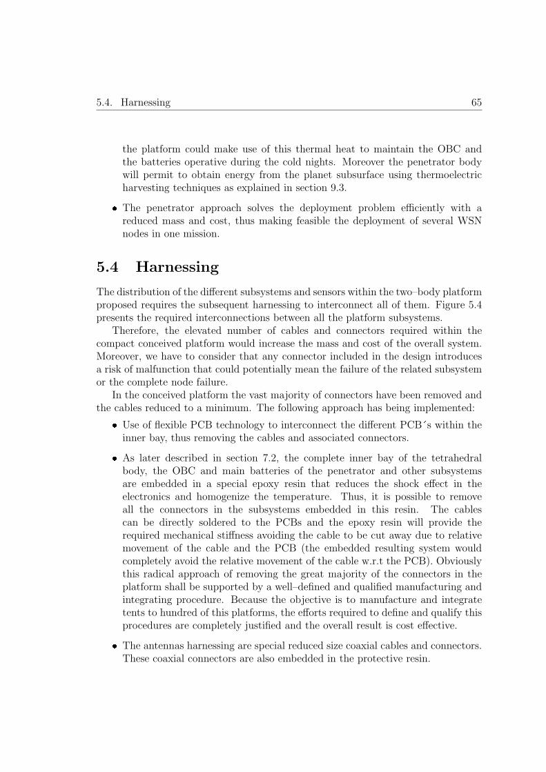
5.4. Harnessing 65
the platform could make use of this thermal heat to maintain the OBC andthe batteries operative during the cold nights. Moreover the penetrator bodywill permit to obtain energy from the planet subsurface using thermoelectricharvesting techniques as explained in section 9.3.
� The penetrator approach solves the deployment problem efficiently with areduced mass and cost, thus making feasible the deployment of several WSNnodes in one mission.
5.4 Harnessing
The distribution of the different subsystems and sensors within the two–body platformproposed requires the subsequent harnessing to interconnect all of them. Figure 5.4presents the required interconnections between all the platform subsystems.
Therefore, the elevated number of cables and connectors required within thecompact conceived platform would increase the mass and cost of the overall system.Moreover, we have to consider that any connector included in the design introducesa risk of malfunction that could potentially mean the failure of the related subsystemor the complete node failure.
In the conceived platform the vast majority of connectors have been removed andthe cables reduced to a minimum. The following approach has being implemented:
� Use of flexible PCB technology to interconnect the different PCB�s within theinner bay, thus removing the cables and associated connectors.
� As later described in section 7.2, the complete inner bay of the tetrahedralbody, the OBC and main batteries of the penetrator and other subsystemsare embedded in a special epoxy resin that reduces the shock effect in theelectronics and homogenize the temperature. Thus, it is possible to removeall the connectors in the subsystems embedded in this resin. The cablescan be directly soldered to the PCBs and the epoxy resin will provide therequired mechanical stiffness avoiding the cable to be cut away due to relativemovement of the cable and the PCB (the embedded resulting system wouldcompletely avoid the relative movement of the cable w.r.t the PCB). Obviouslythis radical approach of removing the great majority of the connectors in theplatform shall be supported by a well–defined and qualified manufacturing andintegrating procedure. Because the objective is to manufacture and integratetents to hundred of this platforms, the efforts required to define and qualify thisprocedures are completely justified and the overall result is cost effective.
� The antennas harnessing are special reduced size coaxial cables and connectors.These coaxial connectors are also embedded in the protective resin.

66 Chapter 5. Self–powered and low mass fixed platform
Figure 5.4: Harnessing overview
The harnessing that connects the surface tetrahedral platform and the penetrator willsuffer from extraordinary efforts due to the tensions generated during the penetrationphase. Additionally the cables rolled in the upper part of the penetrator shall be ableto be deployed at a velocity near the initial impact velocity of the penetrator. Thedeployment of very similar umbilical cables has been studied, tested, reported inthe literature and even patented ( [Canning et al., 1981], [Murphy et al., 1981]).The deployment method described in [Canning et al., 1981] was successfully testedas described in [Murphy et al., 1981] for an arrangement compatible to the oneherein proposed. Therefore a similar deployment method is proposed based in thosesuccessful experiences.
Three different bundles of cables shall be deployed between the surface platformand the penetrator body:
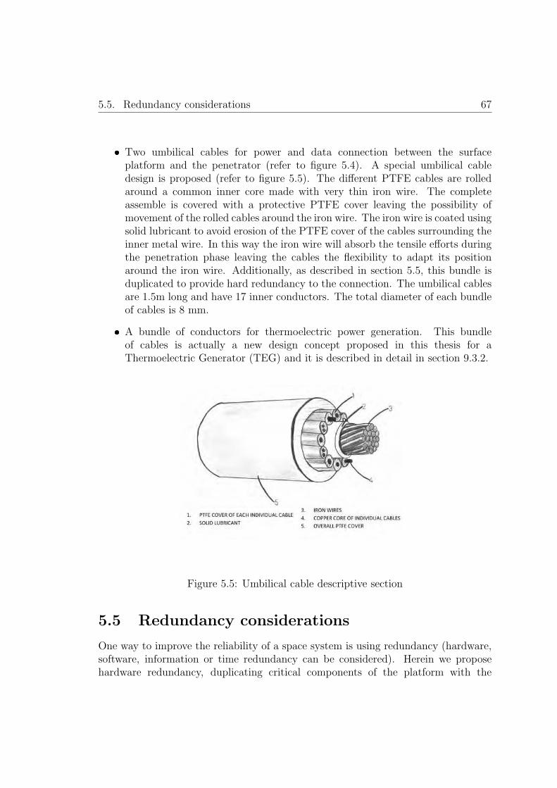
5.5. Redundancy considerations 67
� Two umbilical cables for power and data connection between the surfaceplatform and the penetrator (refer to figure 5.4). A special umbilical cabledesign is proposed (refer to figure 5.5). The different PTFE cables are rolledaround a common inner core made with very thin iron wire. The completeassemble is covered with a protective PTFE cover leaving the possibility ofmovement of the rolled cables around the iron wire. The iron wire is coated usingsolid lubricant to avoid erosion of the PTFE cover of the cables surrounding theinner metal wire. In this way the iron wire will absorb the tensile efforts duringthe penetration phase leaving the cables the flexibility to adapt its positionaround the iron wire. Additionally, as described in section 5.5, this bundle isduplicated to provide hard redundancy to the connection. The umbilical cablesare 1.5m long and have 17 inner conductors. The total diameter of each bundleof cables is 8 mm.
� A bundle of conductors for thermoelectric power generation. This bundleof cables is actually a new design concept proposed in this thesis for aThermoelectric Generator (TEG) and it is described in detail in section 9.3.2.
Figure 5.5: Umbilical cable descriptive section
5.5 Redundancy considerations
One way to improve the reliability of a space system is using redundancy (hardware,software, information or time redundancy can be considered). Herein we proposehardware redundancy, duplicating critical components of the platform with the

68 Chapter 5. Self–powered and low mass fixed platform
intention of increasing the reliability of the whole system. Hardware redundancyimplies higher costs, mass and complexity, however the harsh environment andconstrains of space exploration missions justify the use of hardware redundancy inthose critical systems that are more vulnerable to a previously known possible modeof failure. The conceived two–body platform could present the following most criticalmodes of failure:
� Main OBC failure.
� Principal battery failure or power subsystem failure.
� Radio interface sub-system failure.
� Loss of power and/or data connection between the surface tetrahedral platformand the penetrator body.
In each case a hot or cold standby hardware redundancy technique is proposedas described below. It must be considered that the redundancy techniques hereinproposed are compatible with the low mass and power consumption overall designobjectives of the platform. The approach followed is to use, whenever possible,multiple functionality of the redundant system, thus reducing the impact in theoverall mass.
Main OBC failure.
The main OBC is located in the penetrator body. As previously commented, placethe OBC in the penetrator permits to harvest the thermal energy of the planetarysubsurface with the objective of maintain the OBC and main batteries alwaysoperative. However, during the lander phase the penetrator will be subjected toextremely high shock energy levels. Even considering the design techniques describedin chapter 7, we have to contemplate that the penetrator body is more susceptibleto partial or total failures. This does not mean that the tetrahedral platform wouldnot be subjected to high shock energy levels, although the penetrator will absorb themajor shock levels during the penetration, as it is the first element to impact with theplanet surface as later explained in chapter 7. Consequently it is proposed a hardwarearchitecture where the OBC is duplicated using cold standby redundancy.
The concept proposed is to use the acquisition electronics control FPGA toimplement a redundant OBC with the same functions that the main OBC. A controlunit is, in any case, required to manage all the payload acquisition procedures,therefore the mass impact is limited to the addition of some external elements aslater described in section 5.6.

5.5. Redundancy considerations 69
The acquisition electronics FPGA is powered from the main and auxiliary batteriesand will be in an ultralow power consumption state most of the operational time.The FPGA will wake-up when required from the OBC to perform a scientific dataacquisition procedure. Additionally, every 20 minutes, the acquisition electronics willwake-up during some milliseconds to submit a pulling message to the main OBC.In a normal operation mode, the main OBC will immediately answer to the FPGAacquisition electronics and the latter will enter again in its hibernation low powerconsumption state. If the main OBC fails to answer the acquisition electronics FPGAin three consecutive attempts (in both nominal and redundant lines), the acquisitionelectronics will assume the failure of the OBC and will work as main OBC hereafter.Every 20 minutes the attempt to communicate with the OBC in the penetrator bodywill be repeated to try to restore the nominal operation.
Obviously in the redundant mode, where the acquisition electronics FPGA hasassumed the OBC activities, the performance of the complete system is reduced, whilethe FPGA will switch off when the temperature of the surface platform descent belowthe operational temperature range of the FPGA, thus stopping the node operationsuntil the temperature is again within the operational limits. After the wake-up,the node operated by the redundant OBC, shall resynchronize with the WSN andre-stablish the normal operational mode re-planning its tasks as explained in chapter10.
It is possible that the OBC remains operative but the nominal and redundant linesconnecting the main OBC and the acquisition electronics are damaged. In this case,the OBC would continue commanding other subsystems of the platform as the radiointerface antenna. If this is the case, data collision could occur between the commandssend by the OBC and the acquisition electronics FPGA working as redundant OBC.To avoid this, once the acquisition electronics enters in the redundant mode, the restof the subsystems, as the power module or the radio interface subsystem, would ignoreany command received from the main OBC.
In the case the acquisition electronics FPGA would fail, the OBC would remainoperative implementing the WSN protocols and data distribution within the WSN,however without providing new payload measurements to the WSN.
Principal battery failure or power subsystem failure.
A common power bus (+12V, +5V and +3.3V) is shared by the surface platformand the penetrator body. This power bus is supplied by two sets of batteries:(i) auxiliary batteries in the surface platform (that will be operative when thetemperature of the inner bay is within the operational temperature range of thebatteries) and (ii) principal batteries located in the penetrator body and virtually

70 Chapter 5. Self–powered and low mass fixed platform
always operative.Both sets of batteries are in a hot standby redundancy fashion. Obviously, if the
principal battery set fails the complete platform only would be operative during thetime the auxiliary batteries are operative.
An efficient power subsystem is placed in the tetrahedral platform within theinner electronics bay. A partial duplication of the power electronics is placed in thepenetrator in order to maintain the OBC operative during the cold nights whenthe power electronics of the aftbody is out of its temperature range. The powersubsystem is able to independently switch on and off the different subsystems. Inthis way, any malfunction of a subsystem that could lead in a short-circuit conditionwill not affect the overall platform.
Radio interface sub-system failure.
The radio interface subsystem is a critical element of the platform that cannotbe duplicated because of its high mass and complexity. In case of malfunction theplatform will remain inoperative because it will be unable to communicate with therest of the nodes in the WSN. For this reason the radio interface subsystem shallbe design using high reliability techniques and components. An important elementof the communication subsystem is the antenna. A partial external obstruction ormalfunction of this element would imply the complete loss of the platform, unableto communicate with the WSN. Three antennas will be used in the platform. Eachantenna will be covering 120◦ for a total coverage of 360◦. This approach wouldpermit the node to communicate with the surrounding nodes. In the case of a failureof one or two antennas, the node would be able to communicate if the remainingantenna or antennas are in line with any other surrounding node.
Loss of power and/or data connection between the two-body platformelements.
The cables connecting the surface tetrahedral platform and the penetrator bodyare critical to maintain the overall platform performance. Even though the cablesconnecting both parts of the platform are specially designed to be mechanically robust(refer to section 5.4) this umbilical bundle of cables is duplicated. Two identicalbundles of cables are provided to increase the reliability of this connection.
Cold standby redundancy is used for the data cables: in a normal operation modethe OBC will try to communicate using the nominal line, if not reply is received inthree consecutive attempts the OBC will use the redundant line. This procedure

5.6. Main and redundant On Board Computer architecture overview 71
will be used to switch between redundant and nominal until obtain a successfulcommunication. In the case of the power cables a hot standby redundant approachis followed. Both cables are connected to the power bus in a nominal operation.
Redundancy in the platform overview.
As a result of applying all the previous redundancy techniques it is possible toconclude that the node could maintain its functionality even in the case of majorfailures, as it is the case of the complete failure of the penetrator body and its relatedsubsystems.
Table 5.5 summarizes the redundancy elements interrelation conceived for theplatform.
5.6 Main and redundant On Board Computer
architecture overview
As described in the previous section, the platform proposed conceives two differentOBC (nominal and redundant) distributed in each of the platform bodies. A mainOBC located in the penetrator body and a redundant OBC located in the surfaceplatform (used additionally as control unit for the payload acquisition electronics).
In this section the OBC architecture is presented. This architecture is shared forboth OBC (nominal and redundant), just differing in the firmware loaded in eachsubsystem.
The architecture block diagram is shown in figure 5.6. As it can be seenin the figure, the OBC is based on a RTAX–S radiation-tolerant FPGA fromMicrosemi. Specifically the RTAX2000SL model is considered due to its highlyreliable, nonvolatile antifuse technology and heritage in space systems [Microsemi,2015]. This FPGA is specially suitable for the platform proposed as it includes alow power grade option that half the standby current of standard product at worstcase conditions. The RTAX–S/SL family has hot–swap and cold–sparing capabilities,which enable turn off the device for minimal power consumption during long periodsas required for the platform proposed. The 1.5 V core voltage permits to increase theusage of the batteries even when those are with a low output voltage, increasing inthis way the operational time.
A processor embedded in the FPGA is considered as main processing unit. The32–bit processor LEON–FT is herein considered. The LEON3–FT processor isdesigned for embedded applications, combining high performance with low complexityand low power consumption ( [Gaisler, 2008]). The fault–tolerant version of the

72 Chapter 5. Self–powered and low mass fixed platform
Systemfailure
Redundancy Operational performance
Main OBCCold standby redundancy
Acquisition electronic�s FPGAwould work as OBC.
Reduced. The electronic�s FPGAwould maintain the node performance justwhen the inner electronics bay is within
its operational temperature range. Thereforeduring a great part of the lunar nights the node
would enter in a hibernation mode.
Acquisitionelectronics
Cold standbyredundancy.
The main OBC willmaintain its operability.
Highly reduced.The node will maintain its
performance as part of the WSN but withoutproviding new scientific data to the WSN.
Auxiliarybatteries
Hot standbyredundancy.
Both set of batterieswork in parallel.
Slightly reduced.The work cycle of the node would be reduced.
Mainbatteries
Hot standbyredundancy.
Both set of batteriesworks in parallel.
Reduced. The auxiliary batteries wouldmaintain the node performance just whenthe inner electronics bay is within theoperational temperature range of the
auxiliary batteries.Therefore during a great part of the
lunar nights the nodewould enter in a hibernation mode.
One umbilicalbundle ofcables
Hot standbyredundancy.
Two different bundles ofcables maintain
theconnection betweenthe two platforms.
Complete. The redundant bundle wouldmaintain a normal operation.
Penetrator bodyor the two
umbilical cables
Cold standbyredundancy.
The surface platformwould work
independently.
Reduced. The electronic�s FPGAwould maintain the node performance justwhen the inner electronics bay is within
its operational temperature range. Thereforeduring a great part of the lunar nights the node
would enter in a hibernation mode.
One or twotemperature
probes
Hot standbyredundancy.
There are threetemperature probes
measuring thesoil temperature
in parallel.
Complete. The remaining operativetemperature probes would obtainthe required soil temperature..
Table 5.1: Platform redundancy summary
LEON3 processor in combination with the radiation tolerant Microsemi RTAX FPGAgives a total immunity to radiation effects.

5.7. Platform mass budget 73
Figure 5.6: Nominal and redundant OBC architecture block diagram
The system requires a boot sequence as in SRAM-based FPGAs there is need todownload their configuration code from an external storage device (Boot memory inthe figure). An external memory will expand the internal memory of the LEON3–FTprocessor. In this way it is possible to store the data obtained from the scientificpayload (from the platform itself and from other platforms of the WSN) until theconditions of energy, temperature and satellite link are adequate for a data uploadprocedure.
The OBC could enter into an infinite loop due to malfunction (radiation orunexpected behavior of the software program). The use of an external watchdogis herein proposed as safeguard to restore the OBC functionality. External ultra-lowpower digital ASIC implements a counter designed to rollover after 5 seconds. TheOBC is programmed to reset the watchdog timer before 5 seconds. If the OBC entersin a malfunction mode the watchdog timer will not be reset and the watchdog devicewill reset the FPGA and the application memory. The firmware will be reloaded inthe FPGA to re–start the OBC nominal operation. The digital ASIC implementingthe watchdog shall be rad–hard and implement high reliability design techniques.
5.7 Platform mass budget
Table 5.2 presents the complete platform mass budget. This budget includes themass estimations for each subsystem, either work–out theoretically from the design

74 Chapter 5. Self–powered and low mass fixed platform
or experimentally based on the prototype subsystems developed. It is possible to seethat the mass budget is very tight and challenging to accomplish. A safety margin of10% has been considered given the uncertainty of the estimations.

5.7. Platform mass budget 75
SubsystemMass
(grams)Notes
Tetrahedralaluminium structure
520Obtained
from prototypeInner
electronics bay(with epoxy and MLI)
545 Estimation
DDS 40Obtained
from prototypeSurface
temperature sensors (x3)9
Obtainedfrom prototype
Radiationsensor
10Obtained
from prototypeIrradiancesensor (x3)
25.5Obtained
from prototypeHarnessing 120 Estimation
Solarpanels
275 Estimation
Thermalswitch
117Obtained
from prototypeRelease
mechanism60
Obtainedfrom prototype
Antennas(x3)
30 Estimation
Externalstructure shock protection
materials65
Estimation.Not including epoxy resin considered
in the mass of the innerelectronics bay.
Safetymargin
10%Margin
considering uncertaintiesin the estimations
Surfaceplatform
TOTAL surface platform 1998,15
Penetratorstructure
1250Estimation.
Including shockreduction structures.
OBC 75 EstimationHarnessing
(umbilical cables +deployment system)
435 Estimation.
ThermoelectricGenerator
800 Estimation.
Powerelectronics
120 Estimation.
Mainbatteries
205Estimation.
Based on [RD8]Shock
protection materials75
Estimation.Aluminium foam.
Safetymargin
10%Margin
considering uncertaintiesin the estimations
Penetrator
TOTALpenetrator body
3256
Two–body platform TOTAL 5254.15


Chapter 6
Scientific low mass and low powerconsumption payload
77


6.1. Scientific payload conceived 79
6.1 Scientific payload conceived
The ultimate objective of the exploration platform proposed is to obtain scientificmeasurements of the planetary surface aimed to achieve a better understanding ofthe planet, moon or asteroid.
The selection of the scientific payload, in the frame of an exploration mission, isalways a decision of high responsibility shared among the different mission sponsors.Depending on the mission, the scientific payload has to adapt to the technologicalsolutions proposed for the mission itself, or in other cases, are the scientific objectivesthe drivers that stablish the requirements for the technical solutions proposed.
In the frame of this thesis the main objective of the technologies proposed is toobtain a new low power and low mass payload set of planetary surface explorationsensors that could be used in different exploration missions for environmentalcharacterization. The main requirements for the scientific payload proposed are thefollowing:
� Complexity. The sensors shall be compatible with the platform conceived. Lowmass and low power consumption sensors shall be proposed.
� Environmental characterization. As described in section 1.4, the hardenvironmental constrains are a limiting factor for the planetary spaceexploration. The set of sensors selected shall be able to characterize as manyas possible relevant environmental parameters to increase our knowledge aboutthe planetary surface under exploration.
� Valid for different targets. The reutilizations of the same sensors for differentplanetary surface targets would increase the number of missions were theproposed platform could be useful, also reducing the cost of reutilization. Thesensors herein proposed are dimensioned for a Moon scenario (refer to section3.2.1), although all of them are compatible with other objectives as Mars ordifferent asteroids.
In the scope of this thesis a fixed set of sensors has been selected. Although we haveto consider that this would not be the case for a mission using the concept of platformenvisaged. Since the concept proposed is to deploy a large number of platforms thatwould generate an ad hoc Wireless Sensor Network, it would be possible to modify thescientific payload in each platform. Thus covering a large number of different scientificmeasurements, without increase the mass or the volume of each platform individuallyor the mission as a whole. Some other sensors compatible with the platform proposedare: seismic sensors (as introduced in the state of the art previously proposed inLunar-A or MoonLITE missions), atmospheric pressure (just for missions in planets

80 Chapter 6. Scientific low mass and low power consumption payload
with gaseous atmospheres), magnetometers, soil thermal and electrical conductivity,water presence sensors, camera or microphone.
The set of sensors selected was found the most advantageous solution that satisfiesthe requirements described above and better exploits the synergies with the platformconfiguration proposed. In the following subsections the design solutions proposed forthe different sensors are described in detail. The science payload selected is focusedon the atmospheric science of the Moon.
6.2 Dust Deposition Sensor
6.2.1 Introduction and requirements definition
As described in section 1.4, the dust is one of the main environmental constrains forspace exploration. Its characterization is of main importance with the objective ofdesign space exploration subsystems tolerant to this environmental phenomenon.
The Dust Deposition Sensor (DDS) herein presented is designed to characterizethe rate of lunar dust deposition over a horizontal planar surface by natural meansin function of time ( [Alvarez et al., 2014]. The dust characterization shall be doneexcluding man-made disturbances such as during the Apollo missions. This data willbe very valuable in understanding the dynamics and hazards of dust over the Moonsurface, at the moment being only barely theorized ( [Stubbs et al., 2006] and [Grunand Horanyi, 2013]). The dust deposition rate over the Moon surface has not beenexperimentally characterized.
6.2.2 Proposed Dust Deposition Sensor design
From the know-how obtained in previous experiences ( [Alvarez et al., 2011]), anultra-low mass, reduced volume and low power consumption DDS has been designedand manufactured. This sensor is based on optical Mie scattering and fulfils therequirements for lunar surface operation.
The sensor is located on the top part of the tetrahedron, at approximately 133 mmof the lunar surface. This location is of main importance for the following reasons:
� The distance to the soil is enough to avoid dust to be attracted directly fromthe moon surface to the sensor surface due to electrostatic charge.
� Considering the ballistic trajectory theorized in [Stubbs et al., 2006] (refer tofigure 6.1) the dust particles, in their descent trajectory, will be deposited overthe sensor surface by natural means. Considering the model results (refer tofigure 6.1 right) of Stubbs� dynamic fountain model, the great majority of

6.2. Dust Deposition Sensor 81
levitating particles will reach 133 mm of height. Particles as large as 1μmin radius could be deposited over the optical window of the sensor.
At the top of the tetrahedron there is no other element of the platform thatcould disturb the dust particle descending trajectory.
Figure 6.1: Dust ballistic trajectory (left) and dust grain maximum height reached infunction of the dust grain radius and subsolar point location (right) following Stubbsdynamic fountain model (extracted from [Stubbs et al., 2006]).
The working principle is as follows ( [Alvarez et al., 2015]): Infra-Red (IR) pulsesof light are emitted directly towards a high IR transmittance optical window. Thiswindow, which is positioned horizontally to the Moon surface, will accumulate thedust on it by natural deposition means. An IR detector is situated geometrically outof the path followed by nominal IR ray-pulses. The dust particles deposited over theoptical window will scatter the IR rays changing their nominal paths and letting themto hit the detector, thus obtaining a measure at the IR detector as a function of thequantity of the dust (refer Figure 6.2).
In order to comply with all the challenging environmental constrains and propose asensor compatible with the platform herein proposed, the following design approacheshave been considered:
Laser technology could not be used, as it was considered costly, heavy andpower consuming for the platform conceived in this thesis. As an alternative,Laser Emitting Diode (LED) technology employing smart pulsing techniqueswas selected. IR pulses of quite short duration (below 1μs) but with a veryhigh optical output energy were used. The duty cycle was defined in order topermit optical energy outputs above 1W without damaging the emitter.
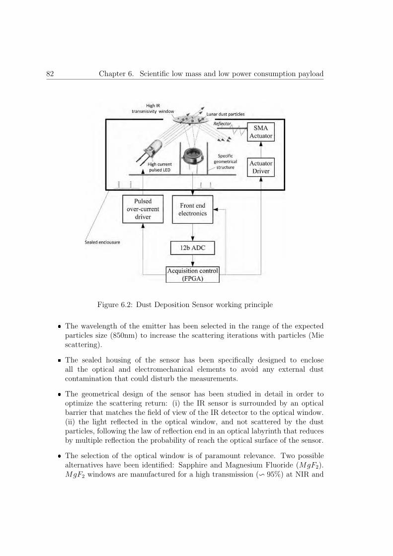
82 Chapter 6. Scientific low mass and low power consumption payload
Figure 6.2: Dust Deposition Sensor working principle
� The wavelength of the emitter has been selected in the range of the expectedparticles size (850nm) to increase the scattering iterations with particles (Miescattering).
� The sealed housing of the sensor has been specifically designed to encloseall the optical and electromechanical elements to avoid any external dustcontamination that could disturb the measurements.
� The geometrical design of the sensor has been studied in detail in order tooptimize the scattering return: (i) the IR sensor is surrounded by an opticalbarrier that matches the field of view of the IR detector to the optical window.(ii) the light reflected in the optical window, and not scattered by the dustparticles, following the law of reflection end in an optical labyrinth that reducesby multiple reflection the probability of reach the optical surface of the sensor.
� The selection of the optical window is of paramount relevance. Two possiblealternatives have been identified: Sapphire and Magnesium Fluoride (MgF2).MgF2 windows are manufactured for a high transmission (� 95%) at NIR and

6.2. Dust Deposition Sensor 83
they do not loss its properties after long radiation exposure as experimentallydemonstrated in [Finckenor, 2006]. Sapphire transmission coefficient at NIR islower (� 85−90%), although it has been traditionally used due to its stable androbust behavior in temperature and its mechanical stress. MgF2 was selectedfinally due to its better transmittance and radiation tolerance.
The sensor includes an in-flight calibration system using a diffuse reflector whichreflects the light emitted directly to the detector when the actuator system iscommanded to do so. This will permit to use a known pattern for in-flight calibrationto correct aging or other deviations of the entire measurement chain (detector,emitter and related electronics). A specific ultra-light actuator (10 g) based inSMA technology has been specified and designed by the mechanical department ofArquimea Ingenierıa. Results obtained are presented in chapter 10.5. In contrast,against the simplicity of this actuator, and its low mass and volume characteristics itis important to consider the power consumption for each actuation. The total energyconsumed by the actuator per each calibration procedure (in vacuum at 20◦C) willbe around 150 J. This kind of actuator fits very well applications where there is needof an ultra-low mass/volume actuator that will be used occasionally (as it is the DDScalibration actuator).
The acquisition front end electronics is of main importance and very challengingfor this sensor. It shall be able to measure fast pulses of current with the higherpossible dynamic range. An energy integration technique, proposed by the electronicsdepartment of Arquimea Ingenierıa and based on the use of a low offset amplifier,has been selected for the DDS front-end acquisition electronics. This techniquepermits to acquire the DC output as a function of the total energy obtained in thedetector. Additionally the technique allows an increase of the dynamic range bymodifying dynamically the light emission time (possibility to adapt the integrationtime in function of the return signal). This measurement technique prevents thedust measurements during the Moon day because the ambient light will disturb thequantification of the scattered light pulses measurement. For this reason, the DDSshall be operated right after the moon Sunset, providing a high accuracy measurementof the dust deposited over the last Moon day.
The acquisition control FPGA will be responsible for sequencing all the sensingprocedures: (i) firstly ten optical measurements of the IR ambient light are performed(non-activated emitter) (ii) secondly the actuator will be commanded to move the IRreflector reference in the light path, the emitter is activated and a value obtained.This will be used as calibration measurements. (iii) Finally the measurement of thedust is performed.
The total mass of the DDS (including the actuator, PCB, screws and harnessing)is 40 grams. The DDS functional prototype is shown in figure 6.3.
The sensor proposed is aimed to measure dust deposited over its surface by natural

84 Chapter 6. Scientific low mass and low power consumption payload
Figure 6.3: DDS and auxiliaryelectronics. Functional prototype.
means. Therefore, it is of major importance reduce to a minimum the robotic systemdisturbances during the measurement. This is challenging task while the deploymenttechnology considered for the platform is by hard landing (penetrator). Additionallywe have to consider the solar panels deployment once the platform is over the lunarsurface. The strategy followed to avoid these two problems is following described.
During the landing, the impact of the platform and the penetrator will eject a hugeamount of dust at a height of kilometers ( [Gaier, 2005]). It is of main importancethat this ejected dust will not reach the sensor surface. This goal is achieved dueto the configuration of the platform. The platform will be closed during the landingand around 1.5 or 2 months after the landing (this time will depend on the landingtime to synchronize the opening with the lunar day). During the time the platformremains closed over the Moon surface, the dust ejected will be slowly deposited overthe Moon surface and the external walls of the platform. Additionally, during thistime the sublimation of the protective material within the platform will take place(this is detail described in chapter 6). Thus, the sensor (inside the platform) will notbe contaminated during this process.
After the first stage is completed (sublimation process concludes and the subsolarpoint is favorable to harvest solar energy to charge the batteries), the platform isready to deploy the solar panels. Once the solar panels are deployed the DDS will beexposed to the dust. For this reason the solar panels deployment has been designedto reduce at a minimum the dust ejection:
� It is important to note that the Moon surface can be considered to have nearlyvacuum conditions (refer to table 1.1), consequently the absence of gas flowingduring the deployment of the petals will not imply dust ejection.
� An important difference in the total electric net charge of the solar panels andthe lunar soil could cause dust ejection, and consequently contamination of thedust sensor. For this reason the metal frame of the solar panels and the wholestructure shall ensure a good electrical connection (below 10mΩ). During the

6.3. Radiation sensor 85
time the closed structure is exposed to the lunar surface, before the solar panelsdeployment, and considering the direct contact of the platform with the lunardust, it is considered that the solar panels deployed are at the same electricalnet charge that the surrounding dust.
� It is unavoidable in any case that the sensor will be contaminated as a resultof dust ejected from the solar panels deployment. For this reason the firstmeasurement of the DDS shall be performed several days after the platforminitiates its scientific mission: once the amount of dust ejected during thedeployment procedure is settle down the first measurement will be consideredas the reference. The dust deposition rate, during the lunar day/night cycle,can be obtained as the incremental measurements from this initial value.
6.3 Radiation sensor
6.3.1 Introduction and requirements definition
Radiation is an environmental parameter of major importance. As described insection 1.4, the radiation effects are certainly harmful, not only for the astronaut�shealth, also for the robotic subsystems (specifically for the electronics).
The main objective of the radiation sensor herein proposed is to obtain long-terminformation about the radiation over the Moon surface. This long term data obtainedsimultaneously by the different nodes of the WSN concept herein proposed will beof great help in order to eventually enable future human long term presence inthe Moon surface. The SWIPE concept mission contemplates the Moon surfaceexploration using a WSN of tents of nodes spatially distributed over an area witha specific scientific interest. As described in [Rodrigues et al., 2014], one of the mostinteresting local features on the Moon�s surface are swirls. Swirls have a high albedosuch as the Reiner Gamma swirl ( [Hood et al., 2001]) and tend to be associatedwith magnetic anomalies ( [Halekas et al., 2001]). These anomalies have not beenstudied in detail yet and there is not much information available about them. Thereare several different swirl locations on the Moon surface, divided between nearsideand farside. By analyzing different locations against several features of interest ofthe Moon, Mare Ingenii is the site that gathers the highest number of interestingelements, from a scientific perspective.
The SWIPE mission concept considers the deployment of around 10 to 20 nodesto monitor a region of 5 km2 to include the curling shape of a swirl in the MareIngenii. As described in figure 6.4 the radiation environment over the Moon surface israther complex and requires a challenging sensor in order to characterize the completeradiation scenario. The requirements for the radiation sensor are listed below:

86 Chapter 6. Scientific low mass and low power consumption payload
Figure 6.4: Summary of the three major types of radiation in the lunar environmentcollected by instruments on spacecraft beyond the Earth�s magnetosphere (extractedfrom [Heiken et al., 1991])
� Capability of measuring long term radiation over the Moon surface and at thesame time be able to monitor punctual radiation events.
� Large dynamic range. As shown in figure 6.4 the radiation that are expectedto reach the Moon surface have a very large energy range, from KeV to GeV,what represents 6 orders of magnitude.
� Low power consumption and reduced mass and volume.

6.3. Radiation sensor 87
� Tolerant to dust exposure.
6.3.2 Proposed radiation sensor design
The previously listed requirements for the radiation sensor represent a real engineeringchallenge. The solution proposed is to use the known effects of the radiation over theelectronics for radiation monitoring. This solution is based in the measurement of theeffects generated by the radiation in some parameters of certain electronic devices.The electronics devices would be completed characterized in the laboratory, usingradiation sources in order to obtain the behavior under certain radiation conditions.If the response of the electronic devices is repeatable it would be possible to calibratethe device response and use it as a radiation sensor.
Obviously the auxiliary electronics used for the polarization of the sensor anddata acquisition has to be tolerant to the radiation environment in which the sensoris working. Application-Specific Integrated Circuits (ASICs) are custom devices thatpermit to integrate specific circuits in a single device. This reduces significantly themass and power consumption increasing the reliability.
Hence, the sensor initially conceived is based in the use of a radiation hardenedmixed signal ASIC that will integrate some elements susceptible to modify theirproperties due to iteration with the ionizing radiation received.
The Microelectronics Group of the Arquimea Ingenierıa Company is a groupexpert in the development of radiation hardened mixed signal ASIC using Europeancommercial technologies ( [Lopez-Soto et al., 2014]). This group analyzed the sensorrequirements and proposed two different techniques for radiation measurement:
� A SEUs sensor design based on digital Shift Registers (SRs). This sensorwould be based in four digital SRs (128b) with different susceptibility to SEUs.Because each SR is susceptible at different Linear Energy Transfer (LET) levelsit will be possible to estimate a statistical occurrence of SEUs at different LETlevels. The 4 LET levels stablished by design for the sensor are 0.90, 9.75, 30and 60 MeV · cm2/mg.
� TID sensor monitoring the leakage current of integrated MOSFETs withdifferent layout characteristics for different dose rates.
These LET levels cover a great part of the energy level of SEUs expected over thelunar surface (figure 6.4). However it was found that the MOSFETs integrated wouldhave a much elevated tolerance to the radiation (>50 Krads) that the TID expectedover the lunar surface ( [Mazur et al., 2015]).
For this reason a search on external compatible transducers with the requirementsabove stated was accomplished. The RADFET model RFT300-CC10G1 from REM

88 Chapter 6. Scientific low mass and low power consumption payload
Oxford Ltd. was selected ( [REM, 2009]). This device is a low dose rate transducerable to work with 0V bias during the expose mode, thus increasing the TID valuewithout requiring power consumption. The auxiliary electronics for measuring theradfet device was also included in the ASIC.
The technology selected for the design and manufacturing of this ASIC byArquimea�s Microelectronics Group was a European commercial high voltagetechnology with proven radiation heritage. The ASIC has been made tolerant toradiation using different radiation hardening techniques: Enclose Layout Transistors(ELTs), systematic guard rings to avoid latch-up between nMos and pMos transistorsor Triple Modular Redundancy (TMR) among others. The ASIC also includes theauxiliary front-end electronics; a multiplexing and switching system to measure allthe integrated sensors and a configurable charge amplifier to provide a normalizedoutput signal as described in Figure 6.5.
The TID sensor is composed of internal and external transducers as previouslyintroduced. The internal transducers consist on 8 integrated nMOS transistors withdifferent sizes and different layout. The leakage current (drain to source current whenthe gate is grounded) is measured using an integrated charge amplifier. An analogeight channel multiplexer is used to select the output of each integrated MOSFETusing the external ADC of the acquisition electronics (refer to section 6.5.4). Theminimum expected response of this transducers is above 50Krads. The resolution,accuracy and range of these TID transducers shall be characterized during a radiationcampaign (out of the scope of this thesis).
The external TID transducer model RFT300-CC10G1 has a responsivity in therange of 0.2 mV/rad at source to drain voltage in a zero-bias mode for low dosesrates. This TID transducer has the following characteristics:
� Resolution: ±6 rad.
� Accuracy:±12rad.
� Range: 20 to 50000 rad.
The precise transfer function shall be revised after experimental calibration procedure(radiation campaign). Considering a +12V voltage input from the power module tothe ASIC the transfer function would be as following:
V0[V ] = 1.243·�Vt (6.1)
Where �Vt can be obtained from the calibration curve provided by the manufacturerFigure 6.6 (red line of the Bias 0V curves).
The ASIC includes a precise current source in order to bias the RADFET. Aprecise bandgap allows to obtain a voltage reference for this current source.
6.3. Radiation sensor 89
Figure 6.5: Block diagram of the rad-hard mixed signal ASIC designed by themicroelectronics group of Arquimea Ingenierıa for the radiation sensor aimed tomonitor radiation over the Moon surface
A shown in Figure 6.7, the ASIC is encapsulated in a CQFP-64 package. A specificPCB has been designed for mechanical fixing to the node platform using four M3screws. A PCB will be used to integrate the ASIC and auxiliary electronics (RadFet,connector, decoupling capacitors and external resistors). This PCB is located at theend corner of one of the petals as it can be seen in figure 5.2. The total mass of theradiation sensor (including the ASIC, PCB, auxiliary components and harnessing) is10 grams.

90 Chapter 6. Scientific low mass and low power consumption payload
Figure 6.6: Calibration curves of the RADFET used (extracted from [REM, 2009]
Figure 6.7: Radiation sensorfunctional prototype (RADFETnot included)
6.4 Multispectral Irradiance sensor
6.4.1 Introduction and requirements definition
Solar radiation is the main energy source available over the Moon surface.Furthermore, the Sun irradiation rules the lunar surface temperature variation as

6.4. Multispectral Irradiance sensor 91
modeled in chapter 8. The solar radiation monitoring over the Moon surface is a keyparameter for manned and unmanned lunar surface exploration missions. For thesereasons a low power consumption and low mass multispectral irradiance sensor hasbeen conceived as part of the scientific payload proposed.
The objective of the Multispectral Irradiance sensor is to monitor the spectralsolar irradiance conditions over the Moon surface. As primary energy source, thecharacterization over the Moon surface of the radiation received in function of thespectral range, time of the lunar day and levitating dust will be very useful in orderto design the best solar panels for the maximum efficiency over the Moon surface(design of filters, coatings, peak of frequency response, etc.).
The Irradiance of the Sun at 1 Astronomical Unit (1AU = 1, 49597890· 1011m) isdesignated as the solar constant. Figure 6.8 presents the irradiance spectra of theSun at 1 AU.
Figure 6.8: Solar Irradiance spectrafor a total integrated irradiance of1367.28 0.02 W/m2 (Extracted from[Tobiska et al., 2000])
The requirements for the multispectral irradiance sensor are the following:
Low mass and low power consumption sensor compatible with the platformconceived.
Able to measure the irradiance in the ultraviolet, infrared and visible spectralranges.
Large dynamic range able to cover the maximum irradiance levels at eachfrequency as expected over the Moon surface.
92 Chapter 6. Scientific low mass and low power consumption payload
� Omnidirectional. The node disposition w.r.t the Sun is not known. The sensorshall be able to monitor the Sun irradiance independently of the node positionand the Sun angular elevation w.r.t the lunar surface.
6.4.2 Mathematical model for Moon�s surface solarirradiance estimation
As commented previously, the solar irradiance rules most of the dynamic changes overthe Moon�s surface as the temperature or the energy available. A mathematical modelthat provides the solar irradiance in function of the date (year, month, day and hour)and the selenographic altitude and latitude has been developed and implementedusing Matlab software. This model has been used for the following purposes in thisthesis:
� To dimension and validate the design of the Multispectral Irradiance Sensor.
� As input for the lunar surface temperature model (section 6.5.2).
� As input for the Thermal Mathematical model and thermal design stablishedin chapter 8.
� For the autonomous control of the platform described in chapter 10. Theplatform could autonomously estimate the near upcoming irradiance conditionsover the lunar surface and plan in this way its activities.
If the mathematical model developed has to be useful for all the above statedobjectives, then it has to comply with the following requirements:
� The processing effort shall be reduced to the minimum possible. The OBC shallcompute the algorithm proposed for the tasks planning during the mission. Lowpower consumption is directly related with the processing effort required by themathematical model.
� The time resolution shall be compatible with the planning requirements of thenode and the thermal variation change over the lunar surface. It has beenstablished a resolution of 1 hour for the mathematical model. The irradianceillumination variance during 1 hour is approximately around 9W/m2 (in theworst case during the Sunrise). This value represents nearly the 0.65% ofthe total irradiance change. Therefore 1 hour is considered an adequate timeresolution for the planning and design objectives of the mathematical model.Additionally it has to be considered that a higher time resolution would implya much higher processing effort, thus resulting in elevated power consumptionduring the tasks planning.

6.4. Multispectral Irradiance sensor 93
� An adequate spatial resolution has to be considered. The coordination systemselected to stablish the position of the platform over the Moon surface isthe selenographic coordinates of the Moon, as described in the he report ofthe IAU/IAG Working Group on Cartographic Coordinates and Rotationalelements: 2006 ( [Seidelmann et al., 2007]). The selenographic system is verysimilar to the one used in the Earth: latitude measures the distance northor south of an equator defined to be approximately 90�from the rotation axis,while longitude is measured east and west from an arbitrarily chosen centralmeridian. The origin of the coordinate system passes through the point that ismost nearly, on average, pointed towards the centre of the Earth.
The main assumptions and simplifications considered for the development of thismathematical model are the following:
� The Moon is considered a perfect sphere of 1737.4 km in radius, as referencedin the report of the IAU/IAG Working Group on Cartographic Coordinates andRotational elements: 2006 ( [Seidelmann et al., 2007]).
� It has not been considered the dust absorption distortion. The dust absorptiondistortion is considered to be negligible for the objectives of the algorithm hereindeveloped.
� No surface irregularities influences. Mountains and craters influence directlythe solar irradiance received by the platform. This assumption will notaffect the use of this mathematical model for the design objectives hereincontemplated, although for the planning of the platform will involve animportant factor. Geographical irregularities are not contemplated in this thesisfor the mathematical modeling, future works could use the irradiance sensordata obtained during the first lunar day in order to correct the mathematicalmodel automatically over the Moon surface to consider the shadowing effects.
� No Earth eclipses considered. The Earth eclipses could be included in the modelincluding a third body (the Earth) in the Sun-Moon equations herein used. Thiswould change drastically the model complexity increasing the power requiredfor the processing. This phenomenon can be obviated considering the totaleclipses would not be a frequent phenomenon (total or partial eclipses over theMoon surface in the period 2001- 2005 were 7, [Racca, 1995]). Additionally wehave to consider that the platform is designed to be able to operate correctlyduring the approximately 4 hours that the solar irradiance is below the 60% ofthe solar irradiance without eclipse.
The mathematical model elaborated is based on the work of [Li et al., 2008] andadapted to the requirements of the model described above. Solar irradiance of the

94 Chapter 6. Scientific low mass and low power consumption payload
lunar surface can be obtained from the total solar irradiance at moon distance andthe angle of incidence over the lunar surface a:
I = S0· (Rsun−moon(t, λA))2· sin(a(t, λA, ϕA)) (6.2)
Where: S0 is the constant solar irradiance for 1 AU with a value of 1367.28 W/m2.λA
and ϕA are the selenographic coordinates (longitude and latitude) of the point wherethe platform is situated. RSun−moon(t, λA, ϕA) is the dimensionless Sun-Moon distancerelative to 1AU, that varies in function of the selenographic latitude and longitudeand in function of time. Finally a(t, λA, ϕA) is the solar incidence angle as depictedin figure 6.9 and varies in function of the time and the selenographic coordinates.The solar incidence angle has been selected in this work as an angle increasing withthe Sun elevation from 0 to 90◦ unlike the common convection used in the literaturewhere the angle of incidence is selected as a decreasing angle with the Sun elevationfrom 90◦ to 0◦. The convention followed in this thesis is a better approximation for alater use of this angle value in the thermal mathematical model developed.
Figure 6.9: Geometrical parameters used in the mathematical model developed
As described in the figure 6.9 the angle a can be calculated as:
a =π
2− (α + β) (6.3)
Where:
α = arccos(sinϕA·ϕd)− cosϕA· cosϕd· cos(λA − λd) (6.4)

6.4. Multispectral Irradiance sensor 95
β = arcsin
⎛⎝ RMoon· sinα√
(R2sun−Moon +R2
Moon·RSun−Moon·RMoon· cosα)
⎞⎠ (6.5)
Where λd and ϕd are the selenographic latitude and longitude of the subsolar pointand varies in function of the time. The subsolar point coordinates and the Sun-Moondistance are function of time and follow the astronomical relations between the solarsystem bodies. These parameters can be calculated precisely using the NASA�salmanac (DE430 released in 2013). Although, the use of this almanac implies the useof hundreds of periodic terms and a data base that are not compatible with a limiteddata storage and low power consumption processing of the platform proposed overthe Moon surface. For this reason, the subsolar point coordinates and the Sun-Moondistance are calculated using the equations proposed by [Meeus, 1991]. Meeus usedthe most important periodic terms obtaining an accuracy of approximately 10�inthe selenographic longitude of the Moon and 4�in the latitude. This approximationis completely adequate for our purposes and simplifies drastically the processingrequirements of the OBC. The 56 equations that relates the Sun position with theMoon position and the latter with the position of the platform in the Moon surface arenot herein presented for simplicity, although the procedure for obtain these equationscan be found in chapter 45 of [Meeus, 1991]. For simplicity the model developedaccepts the date information in the following format: yyyy,mm,dd,hh where yyyy arethe year, mm the month, dd the day and hh the hour from 1 to 24. The astronomicalcalculations used in the algorithm follow the Gregorian calendar, consequently it isnecessary to include in the model the appropriate translation algorithm.
With the objective of verifying the results obtained by the algorithm developed,results published in the literature have been used as reference. The results obtainedfrom the mathematical model match closely the results obtained by other researches,as shown in figures 6.10 and 6.11.

96 Chapter 6. Scientific low mass and low power consumption payload
Figure 6.10: Irradiance values for year 1971 at different latitudes. Results obtainedusing the model developed (top). Results extracted from [Li et al., ] for differentlatitudes (bottom)
The selected selenographic longitude for the results presented in figure 6.10 is60◦E. As it can be seen, except for the polar region, the results obtained matchedbelow the %5 error with respect to the results presented in [Li et al., ].
A specific analysis of the polar region is shown in figure 6.11. As it can be seen,the results obtained match very precisely the results presented in [Badescu, 2012].
6.4.3 Proposed Multispectral Irradiance Sensor design
Three identical irradiance sensors (able to measure the incident irradiance at UV, IRand VIS) are placed at each face of the tetrahedron. This configuration allows toobtain the irradiance independently of the orientation in which the platform has beenpositioned over the moon surface (figure 6.12). Each group of three photodiodes willbe mounted with a separation of 120 for a total field of view of 360◦ as depicted infigure 6.12.
The irradiance sensor will be able to measure the incident irradiance at threedifferent spectral intervals, one at IR, a second one at UV and a third one at the

6.4. Multispectral Irradiance sensor 97
Figure 6.11: Solar Irradiance at 90◦ latitude (top) and −90◦ latitude (center) obtainedwith the model developed for year 1994. Solar irradiance results for year 1994extracted from [Badescu, 2012], chapter 15. North Pole (solid line, bottom figure)and South Pole (dotted line, bottom figure)
Figure 6.12: Disposition of theirradiance sensors on the platformstructure (top view).
visible range. The photodiodes selected and their respective spectral responses arepresented in figure 6.13:
The frontend electronics designed is shown in figure 6.14. The photodiodesoperates in a photovoltaic mode with a 0V bias. The low offset operational amplifier

98 Chapter 6. Scientific low mass and low power consumption payload
Figure 6.13: Photodiodes selected for the multispectral irradiance sensor ([Pacific-Silicon-Sensor, 2010], and [GmbH, 2013] [Optoelectronics, 2015])
used transforms the current generated by the photodiodes into a voltage level. Thisconfiguration provides an input resistance of Rf/A where A is the open-loop gain ofthe op amp. Even though Rf is generally very large, the resulting input resistanceremains negligible in comparison to the output resistance of the photodiodes. TheOperational Amplifiers selected (AD8628 for SWIPE prototype and LMP2012QMLspace equivalent component) are dual low offset and low input bias current operationalamplifiers, specifically suitable for this application. This configuration allows toobtain the required resolution while maintaing a very low power consumption withvery few components (low mass and low power consumption objectives).
The cable connection between the photodiodes modules and the P/L acquisitionboard will be susceptible to induced electromagnetic noise. For this reason the lengthof these cables is reduced locating the acquisition electronics near the irradiancesensors. The cables are twisted and additionally a first order passive low passfrequency filter is used before the ADC in order to reduce any high frequency noiseinduced in the circuit (e.g. clock of the FPGA).
The photodiodes are soldered to a PCB that will be fixed to the surface of thewall of the tetrahedron with 4 M3 screws. Each sensor has a total envelope dimensionof 15x25x9 mm.

6.5. Surface temperature sensor 99
Figure 6.14: Front end electronics(Photovoltaic mode).
The total mass of each group of three photodiodes, the mechanical structure andfixing screws is 8.5 grams.
6.5 Surface temperature sensor
6.5.1 Introduction and requirements definition
Another important parameter is the lunar surface temperature variation during thesynodic period. The Moon has a very large surface temperature variation withtemperatures during the lunar night that can be as low as 100 K at mid latitudes.During the day the temperatures can increase up to 390 K at mid latitudes. As aconsequence the temperature variation is near 300 K. This large surface temperaturevariation entails a challenging problem for future robotic or manned missions.
In order to obtain a complete characterization of the temperature variation duringthe lunar day and night cycle, the surface temperature sensors shall be designed inorder to obtain the following performance.
Resolution:±0.5◦C
Accuracy:±1◦C
Range:−180◦C to 130◦C
6.5.2 Mathematical model for lunar Surface temperatureestimation
A mathematical model, able to predict the lunar surface temperature in function ofthe date (year, month, day and hour) and the selenographic longitude and latitude,has been developed and implemented using Matlab software. This mathematicalmodel is aimed to fulfil the following objectives:
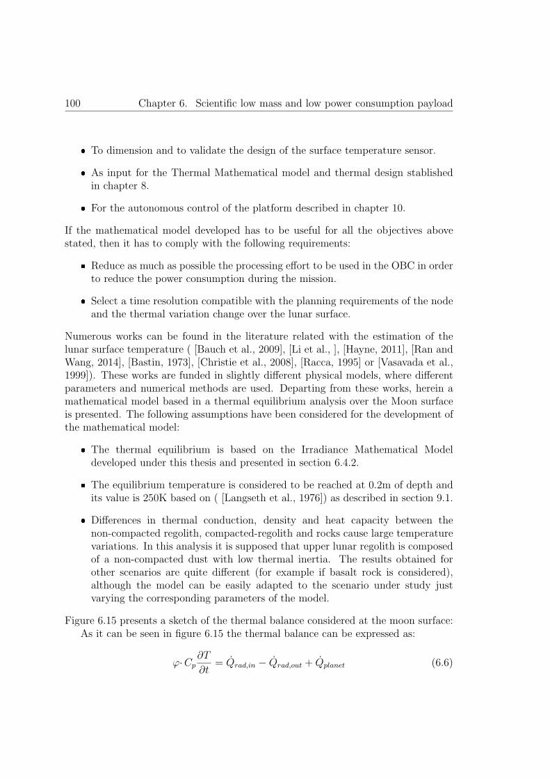
100 Chapter 6. Scientific low mass and low power consumption payload
� To dimension and to validate the design of the surface temperature sensor.
� As input for the Thermal Mathematical model and thermal design stablishedin chapter 8.
� For the autonomous control of the platform described in chapter 10.
If the mathematical model developed has to be useful for all the objectives abovestated, then it has to comply with the following requirements:
� Reduce as much as possible the processing effort to be used in the OBC in orderto reduce the power consumption during the mission.
� Select a time resolution compatible with the planning requirements of the nodeand the thermal variation change over the lunar surface.
Numerous works can be found in the literature related with the estimation of thelunar surface temperature ( [Bauch et al., 2009], [Li et al., ], [Hayne, 2011], [Ran andWang, 2014], [Bastin, 1973], [Christie et al., 2008], [Racca, 1995] or [Vasavada et al.,1999]). These works are funded in slightly different physical models, where differentparameters and numerical methods are used. Departing from these works, herein amathematical model based in a thermal equilibrium analysis over the Moon surfaceis presented. The following assumptions have been considered for the development ofthe mathematical model:
� The thermal equilibrium is based on the Irradiance Mathematical Modeldeveloped under this thesis and presented in section 6.4.2.
� The equilibrium temperature is considered to be reached at 0.2m of depth andits value is 250K based on ( [Langseth et al., 1976]) as described in section 9.1.
� Differences in thermal conduction, density and heat capacity between thenon-compacted regolith, compacted-regolith and rocks cause large temperaturevariations. In this analysis it is supposed that upper lunar regolith is composedof a non-compacted dust with low thermal inertia. The results obtained forother scenarios are quite different (for example if basalt rock is considered),although the model can be easily adapted to the scenario under study justvarying the corresponding parameters of the model.
Figure 6.15 presents a sketch of the thermal balance considered at the moon surface:As it can be seen in figure 6.15 the thermal balance can be expressed as:
ϕ·Cp∂T
∂t= Qrad,in − Qrad,out + Qplanet (6.6)

6.5. Surface temperature sensor 101
Figure 6.15: Thermal balance sketch
Where Qrad,out is the total heat loss due to the IR radiation from the lunar surface,Qrad,in is the heat flux absorbed from the solar irradiation and Qplanet is the geothermalheat flux to the surface. In this thermal analysis, the Moon is considered as a twolayer structure: an inner layer at 0.2m with an equilibrium temperature of 250K andan external layer (the surface) where the temperature is variant in function of thesolar irradiance. The heat diffusion equation between the upper and bottom layercan be expressed as following:
ϕ·Cp∂T
∂t=
∂
∂z
[k∂T
∂z
](6.7)
Where the right term is known as the spatial gradient of the heat flux. From here,initial thermal balance equation is evolved obtaining the thermal equation that willrule the mathematical model developed:
ϕ·Cp∂T
∂t− ∂
∂z
[k∂T
∂z
]= −ε· σ· (T 4
z=0 − T 4space) + (1− r)· I(t, λA, ϕA) (6.8)
This differential equation is solved numerically discretizing in time (1 hour timestep) and in depth (from 0.2m to 0m). It is important to note that the equationis independent of the surface area considered. A brief description of each term ispresented below:
ε is the IR emissivity of the lunar surface (a mean value of 0.97 is used, [Racca,1995]) and σ= 5.669· 10−8 [W/(m2·K4)] is the Stefan-Botzmann constant. Thetemperature of the space (Tspace) is considered 2,7K. r is the reflectivity and, aspreviously commented, I(t,λA,ϕA) is the solar irradiance in function of the time and

102 Chapter 6. Scientific low mass and low power consumption payload
the selenographic coordinates. I can be obtained using the Irradiance MathematicalModel developed under this thesis and presented in section 6.4.3.
The thermal conductivity k is dependent of the temperature and the inter-graindistance. Compact regolith has a better thermal conductivity due to its lowinter-grain distance. The non-compacted first 20cm of the lunar regolith is a reallygood thermal insulator because is composed of fluff dust. The conductivity increasesin function of the depth as the dust is more compacted. The following equation isused for the thermal conductivity ( [Hayne, 2011] or [Li et al., ]):
k(T ) = Kc·(1 + χ·
(T(n)
350
)3)
(6.9)
Kc and χ are parameters in function of the depth. Herein the most restrictivevalues corresponding to the non-compacted top layer of the regolith are used:Kc = 9.22· 10−4,χ = 9.228 (Li 2010). The thermal inertia is the thermophysicalparameter that represents the ability of the surface to adapt to temperature changes:
I = (k(T )· ρ· c)1/2 (6.10)
The thermal inertia can be obtained from the bulk density ρ, conductivity k andheat capacity c of the material. The mean surface density is considered with a valueof 1300 kg/m3 ( [Racca, 1995]). As previously commented herein it is supposeda non-compacted layer of regolith, thus the selected value for thermal inertia is 40J ·m−2·K−1· s−1/2 ( [Bastin, 1973], [Christie et al., 2008] and [Hayne, 2011]). Usingthe inertia relation, the bulk density and the conductivity relation we can obtain theheat capacity of the terrain considered. For the values considered the heat capacityused herein is c=784.15 J/Kg·K what is very similar to the used by other researchers(e.g. [Racca, 1995]).
We have to consider that in this analysis we have used mean values for the densityand the heat capacity. Actually, both parameters vary in function of the depth and thetemperature. Some researchers, as [Li et al., ] or [Hayne, 2011] take into considerationthis phenomenon. The variation can be neglectable for the objectives of the modeland in this way the computational effort of the OBC is optimized.
Finally the left term represents the geothermal heat flux and it can beapproximated at the lunar surface (z=0) as:
∂
∂z
(k∂T
∂z
)∣∣∣∣z=0
�(T(0,2) − T(0)
l
)· k(T ) (6.11)
The mathematical model is numerically solved using Matlab. The detail comparisonof the data obtained with the data published is complex, while the surface temperaturedepends on the date, the selenographic coordinates and parameters of the regolith

6.5. Surface temperature sensor 103
considered. Although, below we can verify the good matching between the dataobtained using the algorithm herein developed and the data published by differentresearches.
Figure 6.16: Lunar surface temperature at equator (bottom left) and 80◦N (top left)in one year extracted from [Li et al., ] compared with results obtained for year 2015with the model developed at the equator (bottom right) and at 80◦N (top right).
As it can be clearly appreciated in figure 6.17, the heat capacity used in bothmodels are different and therefore the day/night transition temperature is moreabrupt in the data obtained from Paige and Vasavada than the one obtained inthe model developed (smother). This can be easily corrected modifying the expectedheat capacity of the expected landing once known the target objective.
6.5.3 Proposed lunar surface temperature sensor
Three temperature sensors are included in the payload. These sensors measure thetemperature by conducting means. The temperature sensor is attached to a highthermal conductivity and low thermal inertia material (aluminum) that will be usedas a probe to measure the upper surface temperature of the Moon (figure 6.18).
During the penetration phase of the deployment (refer to chapter 7 ) the sharpenprobes will be introduced with force in the lunar soil. Some deformation of the probesis expected during the platform deployment. These probes are thermally isolated

104 Chapter 6. Scientific low mass and low power consumption payload
Figure 6.17: Model calculations of lunar surface temperature variations as a functionof local time and latitude extracted from [Paige et al., 2010] after [Vasavada et al.,1999]. Local time is expressed in lunar hours which correspond to 1/24 of a lunarmonth. At 89◦ latitude, diurnal temperature variations are shown at summer andwinter solstices (bottom). Results obtained using the model herein developed (top).
from the rest of the structure. In the base of the probes a thermistor measures thetemperature of the lunar soil.
The temperature probes are located at the base of the tetrahedral platform (nearto the corners).

6.5. Surface temperature sensor 105
Figure 6.18: Temperature probes for lunar surface temperature monitoring (left) andselected thermistor P1K0.232.6w.A.010 ( [IST, 2014]) (right)
The reduced size and the limited number of the components make the mass of eachsensor as low as 3 grams. The three sensors have a total mass of 9 grams (excludingfront end electronics and harnessing).
The selected thermistor P1K0.232.6w.A.010 ( [IST, 2014]) is a very low size andmass Positive Temperature Coefficient (PTC) with a high temperature range (-200 to+600◦C). With the objective to comply with the performance requirements stablishedin 6.5.1 the following front end electronics has been design.
Figure 6.19: Temperature sensors front end electronics and Voltage output range infunction of the PTC resistance values
This configuration has the advantage of obtaining a high linear dynamic rangewith very few components (low mass). The power consumption is maintained low

106 Chapter 6. Scientific low mass and low power consumption payload
by switching off the 0.5V voltage reference when temperature measurement is notrequired. Also the self-heating of the thermistor has to be considered. For thisreason the 1k2 resistors in series with the thermistor will limit the current throughthe thermistor to low values in order to minimize the self-heating problem. Theassociated theoretical transfer function is:
V0[V ] = 0.5 +0.5· (RT + 1200)
499(6.12)
Where RT can be obtained from the following theoretical relations ( [IST, 2014]):From -200 to 0◦C:
RT (T ) = R0· (1 + A·T + B·T 2 + C· (T − 100)·T 3) (6.13)
From 0 to 850◦C:RT (T ) = R0· (1 + A·T + B·T 2) (6.14)
Where: A = 3.9083· 10−3[◦C−1]; B = −5.775· 10−7[◦C−2]; C = −4.183· 10−12[◦C−4]
6.5.4 Scientific payload acquisition electronics
A low mass and power consumption acquisition electronics, located in the innerthermal bay of the platform, is aimed to gather the different analog signals fromthe different transducers and digitize them. Additionally the acquisition electronicsdefined is able to receive, interpret and execute the different commands from theOBC of the platform. The data obtained shall be transmitted to the OBC for furtherprocessing and transmission.
The requirements of the acquisition electronics are quite demanding:
� Low mass (below 40 grams) and low power consumption (main requirement toachieve the objectives of this thesis).
� The electronics for space application must cope with the extremely hardspace environment (in section 1.4 these environmental constrains are defined).For this reason conventional electronics cannot be used. Space qualifiedelectronics shall be considered. A common practice for the development ofpreliminary prototypes in the space industry is herein applied: equivalentcommercial components to those of high reliability have been considered inthe electronic design. In this way, it is possible to manufacture an equivalentof the final electronics and evaluate its performance. Afterwards it willbe possible to introduce the high-reliability components and manufacture aQualification Model that will be used for qualification test of the electronics,once the performance of the electronic design has been verified. Although

6.5. Surface temperature sensor 107
this approach introduces an important limitation to the design because thehigh reliability electronics components for space application is a very limitedmarket where there are available a reduced number of components. Additionallythe performance of those components is far from the obtained using commoncommercial grade electronics components.
� Reduction of the number of components used. Reducing the number ofcomponents it is possible to reduce the number of possible points of failureincreasing the reliability of the complete electronics system and also it is possibleto reduce the total mass.
� The electronics design has to implement high reliability design techniques (worstcase design considerations, components derating following ESA standards ([ECSS, 2011]), Single Point of Failure (SPOF) analysis,etc.). The failure of theacquisition electronics would avoid the node to obtain scientific measurements,therefore the reliability of the system shall be enhanced.
Following, design solutions adopted to cope with the above defined requirements arepresented.
Physically, the acquisition electronics is located in the inner bay of the tetrahedron.In this position the connection of the different sensors to this acquisition electronics iseased. Moreover, in the inner electronics bay the electronics components are protectedfrom the light and dust and also thermally regulated thanks to the thermal switchintegrated in the base of the node (refer to chapter 8 for thermal regulation solutions).Due to the reduced space of the inner bay the acquisition electronics was divided intwo different PCBs. Both PCBs are connected using flex PCB technology in order toavoid connectors (mass, volume and noise reduction).
The acquisition electronics is able to monitor the temperature of the differentsubsystems within the platform: auxiliary batteries, node metal structure,communication module, power module, dust deposition sensor and the acquisitionelectronics itself. Temperature housekeeping data will be of main importance forthe control unit to determinate the best planning (refer to chapter 10). Figure 6.20depicts the main blocks involved in the acquisition electronics design:
� An ADC with an integrated 8 channel multiplexor has been selected. Threedifferent ADC will be used as depicted in the figure. Just one of them will beenabled at a time in order to save power. The ADC selected (ADC128S102) hasa direct space equivalent (ADC128S102QML-SP) with a large heritage in spaceapplications. This device (16-TSSOP or 16-SOIC) uses a serial communicationand permits to have a variable power management. Both characteristics willreduce volume and power of the acquisition electronics.

108 Chapter 6. Scientific low mass and low power consumption payload
Figure 6.20: Low power/low mass acquisition electronics block diagram
� A high resolution Vref (+5V) properly decoupled is used for all the ADCs inorder to provide a precise voltage reference. The space qualified part numberselected is the REF02S.
� Low offset and low frequency precision operational amplifiers are used to adjustthe dynamic range of the analog signals from the sensors to the ADC inputvoltage dynamic range (0 to +5V). Therefore, the operational amplifiers selectedshall permit a rail to rail single supply operation. The commercial modelused for the electronics prototype is the AD8628 dual operational amplifier.The qualified space part number with similar characteristics selected is theLMP2012QML.

6.5. Surface temperature sensor 109
� Low pass passive filters are used to reduce the spurious noise coupled to thesignal (e.g. FPGA�s clock signal).
� With the objective to increase the PSRR of the ADCs, voltage references andoperational amplifiers, it is used a low pass filter composed of an inductanceand a capacitor in all the supplies of these components. Additionally, digitalcomponents are decoupled using 100 nF capacitors.
� The redundant OBC will be used as control unit. A FPGA with spacecompatible solution has been used as main component of this redundant OBC asdescribed in section 5.5. The FPGA voltage required will be 3v3 (obtained fromthe power module) and 1V5 obtained using a voltage regulator integrated in theacquisition electronics PCB. The part number of the commercial componentused is LT1764-1.5 with space qualified equivalent LM117QML. The FPGA, ascontrol unit of the acquisition electronics, is able to work in two different modes:
– Nominal mode. The FPGA is in an ultra-low power consumption statewaiting for a command from the OBC to wake up and perform ameasurement following the commands stablished in table 6.1. Additionally,every 20 minutes the acquisition electronics will wake-up during somemilliseconds to submit a pulling message to the main OBC. If during threeconsecutive attempts, in redundant and nominal communication lines,the FPGA is unable to obtain an answer from the OBC, the acquisitionelectronics will enter in the redundant mode.
– Redundant mode. In case of an OBC failure the acquisition FPGA willenter in a continuous operation mode working as OBC, substituting themain OBC failed as described in section 5.5. Every 20 minutes the attemptto communicate with the OBC in the penetrator body will be repeated totry to restore the nominal operation.
The acquisition electronics is defined in such a way that just a scientific measurementcan be obtain at the same time. In this way the sensors that are not used are notpowered, reducing the power consumption of the electronics significantly.
In a nominal operation mode, the acquisition FPGA works following a pre-definedprotocol. This protocol is command-oriented. The OBC commands the payload toaccomplish a specific task and the payload�s FPGA perform all the required actions tocomplete the operation commanded. This protocol uses an EIA-422 standard physicallayer using space qualified transceivers (HS-26CT31RH and HS-26CT32RH). The linktype is half duplex no flow control link using 8 data bits, parity bit and a date rateof 115.200 bits per second. There are 2 types of packets: command and data. Thereare no handshaking packets except for an acknowledge package.

110 Chapter 6. Scientific low mass and low power consumption payload
A list of commands has been defined and presented in the table below. Withthis set of commands it is possible to operate the acquisition electronics completelyfrom single measurement of individual sensors to a complete or partial measurementprocedures. Also commands for monitoring the status of the acquisition electronicshave been defined.

6.5. Surface temperature sensor 111
Commandmnemonic
CMD ID ExplanationData(bits)
CMD TEST 0x01Sent by the OBC to theP/L to ask the latter
to perform a self-test routine.12
CMD TEMP 0x02Sent by the OBC to the P/L to performtemperature measurement. Measurement
of the three thermal sensors.36
CMD IRRADIANCE 0x03Sent by the OBC to the P/L to performIrradiance measurement. Measurement of
the three irradiance sensors.108
CMD DDS MEASURE 0x04Sent by the OBC to the P/L to perform
Dust Deposition Measurement.12
CMD DDS CAL 0x05Sent by the OBC to the
P/L to perform DDS calibration.12
CMD TID 0x07Sent by the OBC to the
P/L to perform TID measurement.12
CMD SEU 0x08Sent by the OBC to the
P/L to perform SEU measurement.28
CMD FULL PL 0x09
Sent by the OBC to theP/L to perform a complete payload measurement
(including temperature, SEU,TID,DDS and irradiance).
208
CMD HOUSEKEEPING 0x0ASent by the OBC to the
P/L to perform the measurement of the8 housekeeping temperature sensors.
96
CMD STATUS 0x0BSent by the OBC to the
P/L�s FPGA to ask for the measurement status.32
CMD GETDATA 0x0C
Sent by the OBC to theP/L to ask for the
memory dump of the P/L�s internal memory,if the STATUSregister indicates
that there is data available.
Dependson the
operationmode
CMD RAD 0x0DSent by the OBC to the
P/L to perform a SEU and TID measurement.40
CMD IRRADIANCE 1 0x0ESent by the OBC to the P/L to perform Irradiancemeasurement of the irradiance sensor 1 (face 1).
36
CMD IRRADIANCE 2 0x0FSent by the OBC to the P/L to perform Irradiancemeasurement of the irradiance sensor 1 (face 2).
36
CMD IRRADIANCE 3 0x10Sent by the OBC to the P/L to perform Irradiancemeasurement of the irradiance sensor 3 (face 3)
36
Table 6.1: List of commands for the acquisition electronics


Chapter 7
Solutions for the deployment of alarge number of robotic platformsover the planet surface
113


7.1. Trade-off of platform deployment methods 115
In planetary surface exploration missions, the most risky and critical phase of themission is the landing of the robotic systems over the planet surface. During thisphase the robotic systems are subjected to high g-forces and extreme environmentalconditions that could potentially destroy the exploration platform in seconds.Additionally we have to consider that usually some conditions during the landing,as the surface conditions or environmental conditions, are usually barely identifiedor just unknown, what introduce an important risky factor to this mission phase.Several exploration missions failed during the landing phase, including missions withsimilar characteristics of the one herein proposed (e.g. Deep Space 2 mission).
The mission concept proposed is the deployment, over the planet surface, of a largenumber of small autonomous robotic platforms with the objective of generate a WSNfor atmospheric conditions monitoring. Therefore there is need to conceive a realistic(and cost effective) way to deploy a large number (tents) of WSN nodes over theplanet surface. In this chapter a brief review of different deployment methodologiesis presented, afterwards an innovative solution for the deployment of the platform isdescribed and analysed.
7.1 Trade-off of platform deployment methods
Essentially we can difference two type of landing systems in function of the g-forcesapplied to the robotic subsystems during the landing:
� Soft-landing. In soft landing missions the robotic platform includes auxiliarysubsystems to reduce drastically the entry velocity from the orbit to theplanet surface. These auxiliary systems could also include positioning or evenimage processing for landing area selection (e.g. European Lunar Lander).Even though this approximation reduces drastically the g-forces at which therobotic systems are subjected, and therefore reducing the risks of the landingoperation. However, this approach also requires an important extra mass andpower budgets. Most of the planetary surface exploration missions, launched orprojected to be lunched in the near future, use this approximation (e.g. NASA�srovers for Mars exploration).
� Hard-landing. This type of landing approach is based on designing the platformfor surface exploration robust enough to support elevated g-forces. Twosubgroups can be stablished: semi-hard landing approach where an importantpartial reduction of the impact velocity of the lander is provided; or hard-landingwhere the platform shall support extremely high g-forces and there is notvelocity reduction or this is minimum.

116Chapter 7. Solutions for the deployment of a large number of robotic platforms
over the planet surface
Different approaches have been considered for the deployment of the tetrahedralplatform. [Crosnier et al., 2013b], presents a very detailed and complete analysis of thedeployment strategies for SWIPE project. It is important to remember (section 3.1.1),that the SWIPE platform does not include the penetrator body herein describedand that the auxiliary subsystems conceived in this thesis and afterwards describedwere not considered in SWIPE project. Briefly, the deployment strategies analysedin [Crosnier et al., 2013b] are the following:
� Option 1. Use of penetrators dropped from an orbiter spacecraft (hard-landing).Up to 36 nodes per spacecraft (this estimation was directly based on MoonLITEmission considering a total mass of 36 Kgs per node including the penetrator).
� Option 2. Each platform is precisely dropt by a rover. This implies a softlanding of the rover that would carry the nodes (soft-landing). 10-20 nodes of2 Kgs per rover deployed over the planet surface.
� Option 3. Each platform is thrown by a rover. The rover, instead of depositingprecisely the nodes, would drop them by some dropping mechanism (semi-hardlanding). 10-20 nodes of 2 Kgs per lander.
� Option 4. Each platform is thrown by a lander. A traditional landing approachof a big lander would be used to, once the lander is over the planet surface,deploy the nodes using some dropping mechanism (semi-hard landing).
� Option 5. Each platform is thrown thanks to a quasi-lander. During the descentphase of the lander, this would drop the nodes (semi-hard landing).
� Option 6. Each platform is equipped with its own lander (soft-landing). 2 nodesmaximum.
Options 2 to option 6 are in direct conflict with the motivation of this thesis: evenfeasible they would imply a high cost and they would not provide reliability increase(if the landing of the platform or the rover fails the whole mission fails). [Crosnieret al., 2013b] concludes that for SWIPE mission the option 2 is the more optimumsolution while it provides an accurate deployment of 10 to 20 nodes. In this samestudy, option 1 was discarded because the following reasons:
� It is not possible to easily ensure an accurate positioning of the nodes.
� The nodes could be buried during the shock with the planet surface.
� Complex shock requirements would require complex platforms.

7.2. Platform deployment: solution conceived 117
In the following subsection an innovative approach using penetrator technology for thedeployment of a large number of the tetrahedral platforms is described. The solutionsproposed solve the problems detected in [Crosnier et al., 2013b], and additionallypermits to use the deployment energy to harvest the thermal energy present at thesubsurface of most of the planets as afterwards described in chapter 9.
7.2 Platform deployment: solution conceived
7.2.1 General overview
Figure 7.1 presents a rough schematic cross section of the Moon surface extractedfrom [Heiken et al., 1991]: The depth scale in the figure is highly uncertain, becausethe total number of large craters and basins remains unknown. Highly variable deptheffects must exist in different regions, depending on the degree to which an area hasbeen affected by basin-sized impacts.
Figure 7.1: Highly schematic cross-section illustrating the idealized effects oflarge-scale cratering on the structure of the upper lunar crust. (Extracted from[Heiken et al., 1991]

118Chapter 7. Solutions for the deployment of a large number of robotic platforms
over the planet surface
The upper 10 m part of the surface is of interest for the proposed deploymentapproach. It is composed of fine-grained material that nearly everywhere forms thesurface of land and overlies or covers the bedrock ( [Heiken et al., 1991]). A bulletshaped penetrator could use the impact with the surface to enter into the regolithsubsurface of the planet. In the case of the Moon the depth of the regolith variesdrastically depending in the region from 10 to 20 meters in average to just a fewmeters on the maria regions. This has been experimentally verified in the Apollomissions ( [McKay et al., 1974]). Therefore the depth reached by the penetratorcould vary from one region to the other, depending in the regolith characteristics.
The state of the art presents a complete analysis, design and tests results of varioustypes of penetrators: [Gowen et al., 2011], [Gowen et al., 2007], [Doengi et al., 1998],2008 [Gao et al., 2008], 2007 [Gao et al., 2007], [Skulinova et al., 2011], [Lorenz et al.,2000] or [Surkov et al., 1999] between others. It is not the aim of this thesis propose anew penetrator design, considering that an adaptation in size and mass of one of thedesigns proposed in the literature would solve the problem. Nevertheless, this thesisproposes innovative solutions for the subsystems integrated in the penetrator itselfand in the surface platform to survive to the penetration shock.
The general deployment strategy proposed can be summarized in the followingsteps:
1. An orbiter satellite, carrying several nodes, would release the platforms ascommanded from Earth in function of the surface objectives and the WSNpattern configured. This satellite will be used afterwards as communicationlink between the WSN and the Earth.
2. Once the platform is released from the orbiting satellite, a Descent Module(DM) described in section 7.2.2 would permit to control the descending phase.
3. The DM will separate from the platform before the impact with the lunar soil.
4. The two body platform will impact with the lunar surface. As followingdescribed in section 7.2.3, the upper part (tetrahedral platform) will remainat the surface while the penetrator will go buried into the lunar subsurface. Insection 7.2.3 the high shock survival approach conceived for the platform is alsopresented.
5. Once the platform is deployed over the moon surface, the platform will remainclosed during the following two lunar cycles (approximately 2 months) waitingfor the dust ejected during the landing to settle down and also for the shockprotection materials to be partially evaporated from the platform as laterdescribed. Finally the OBC will check the power availability (solar illumination)and will command the deployment of the solar panels, thus starting the surfacescientific measurements.

7.2. Platform deployment: solution conceived 119
7.2.2 The descent phase and descent module
A DM (Descent Module) system is required to ensure an efficient transfer of theplatform once the carrier satellite has released it. The objectives of the DM are:
� Correct the free fall trajectory of the platform. The DM shall provide thetrajectory correction: from the orbital trajectory of the carrier satellite to animpact velocity perpendicular to the planet surface. In principle, with justone thruster the platform could align the trajectory perpendicular to the planetsurface: if the thruster propulsion force is aligned against the horizontal velocityof the circular orbital trajectory, constant propulsion (or constant brake if adense atmosphere can be used) could compensate the initial horizontal forceto near zero. At the same time the gravity will make the system fall verticallydownwards. This approach only considers horizontal surfaces, where the verticalforce added by the planet gravity is perpendicular to the surface. In order tocompensate topography effects additional thrusters are needed to dynamicallyadequate the system trajectory for a perpendicular impact to the surface.
� Release the platform at a determinate altitude. The DM shall release theplatform, before the surface impact, with enough time to ensure itself impactsfar enough from the scientific platform to avoid measurement disturbances.
� Evaluate the topography of the target body and, following ballistic relations,calculate the release angle w.r.t the planet surface to ensure a surfaceperpendicular impact of the platform.
It is important to remark that between the previous objectives a vertical velocitydeceleration is not considered. This is of main importance to reduce the mass andvolume of the DM, just providing the enough fuel to ensure a vertical impact of theplatform. The concept proposed in this thesis uses the penetrator body and additionalshock reduction techniques to handle the high shocks generated during the surfaceimpact of the platform.
To perform the objectives previously listed, the DM shall be provided withcomputational capabilities, fuel, thrusters, instrumentation to dynamically measurethe trajectory and altimeters. Usually, the DM is equipped with an OBC that controlsthe descent phase, gyroscopes and radar altimeters (Doppler effect). Additionally areliable release mechanism shall be provided to release the platform before the surfaceimpact.
The DM (including the solid motors, guidance and navigation control) is not underthe scope of this thesis. For this reason a state of the art analysis was performed andthe preliminary solution provided by the UK Penetrator Consortium, ( [Gowen et al.,2011]) has been selected to be used as reference for the Moon case. This DM has been

120Chapter 7. Solutions for the deployment of a large number of robotic platforms
over the planet surface
selected just for reference purposes as an example of DM where the platform hereincould be adapted. In a future implementation, a specific DM able to perform allthe objectives listed above in an efficient way shall be designed. Also it is importantto note that the DM with a mass of 23Kg, as described in [Gowen et al., 2011], isdesigned to carry a payload of 13Kg. Considering that the platform proposed in thisthesis is just 5.45 Kg the total mass of the DM would be drastically reduced.
Figure 7.2 presents the configuration proposed for the DM adapted to the twobody platform conceived. The interface with the DM is specially conceived to theplatform herein proposed and is composed of the following elements:
� A pressurized compartment where the platform is docked inside the DM. Thecompartment shall be pressurized in order to avoid evaporation of the protectiveresin used to ensure the platform is able to survive the high shock levels at whichis subjected during the landing as later explained in section 7.2.3.
� The docking separation system proposed is a Marman Clamp-band. TheMarman Clamp-Band or simply Clamp Band is a well-known release mechanismsystem used in launchers and other space craft subsystems ( [Lazansky, 2012]).Currently, these subsystems are provided from different manufactures aroundthe world as SAAB or EADS CASA Espacio. The clamp band permits to createa reliable and stiff attachment between the DM and the tetrahedral platformbase plate (note the base plate of the platform can be considered circular insteadtriangular without any variation of the platform design or performance). In thisway, the union between the platform and the DM can be easily made hermeticto include a pressurized compartment as described in figure 7.2.
� A preloaded spring will be pulling out the platform from the DM with enoughforce to ensure a proper separation of both systems when commanded by theOBC of the DM.
� The release actuator considered for the Clamp Band release is a SMA (ShapeMemory Alloy) based actuator from the Arquimea company family of REACT(REsettable Hold-Down and Release ACTuator) devices. The function of theSMA actuator in the REACT mechanism is to perform triggering for the deviceoperation. In this way, it is possible to re-arm the device without requiringa substitution of any element of the release mechanism, what is cheaper anda more reliable approximation than the offered by the standard pyrotechnicdevices that has to be partially substituted after its utilization.

7.2. Platform deployment: solution conceived 121
Figure 7.2: Section of the pressurized compartment and the clamp band systemconceived for docking the tetrahedral platform to the Descent Module (DescentModule based in the concept proposed by the UK Penetrator Consortium, [Gowenet al., 2011] and used as example of Descent Module in the figure)

122Chapter 7. Solutions for the deployment of a large number of robotic platforms
over the planet surface
7.2.3 The surface impact: configuration and high impactsurvival techniques proposed.
As described in section 5.1 the platform proposed is divided in two different bodies:the upper body herein referred as the surface platform or tetrahedral platform andthe penetrator body (bullet shaped), attached at the baseplate to the tetrahedralplatform (refer to figure 5.1). The two different bodies will remain together up to themoment of iteration with the planet surface.
Based on previous studies ( [Skulinova et al., 2011], [Doengi et al., 1998], [Hopfet al., 2010] and [Gowen et al., 2011]) the platform will impact the Moon surfaceat a velocity around 60 to 300 m/s (depending in factors as the planet gravity andatmosphere (table 1.1), DM design and the mass and geometry of the penetrator). Apeak deceleration axial shock in the order of 10.000 g to 50.000 g is expected dependingon mainly the substrate hardness. As previously described, the first meters of a greatpart of the Moon surface are composed of fine-grained material (figure 7.1) that willhelp in smoothing the shock impact (e.g. Lunar-A mission estimated an impact about8000g [Mizutani et al., 2005], while the MoonLITE mission estimated 10000g, [Gowenet al., 2011]).
For the platform proposed, the desired depth of the penetration into the regolithhas been stablished between 0.3 m to 1.2 m. In order to control the penetrator depthit is proposed to use the penetration deformation in the following way:
� The penetrator is missile shaped to ease its penetration into the Moonsubsurface.
� After the initial impact and during the penetration, the penetrator body willbe deformed as a consequence of the impact and contact forces with the lunarregolith. It is important to remember that the lower part of the penetrator doesnot contain any subsystem and it is designed to permit a structural deformation.
� The deformation of the penetrator as it enters in the subsurface will lead to thetwo following beneficial effects:
– Energy is dissipated during the plastic deformation of the penetrator lowerstructure. This shock alleviation technique is well known in the automotivesector to reduce g-force at which the passengers are subjected in anaccident. In the same way, shock-alleviation devices based on irreversibledeformation are used for landers because they offer the highest specificenergy absorption capability. Crushable aluminum honeycombs, foams aswell as deformable tubes are commonly used for shock alleviation ( [Doengiet al., 1998]).

7.2. Platform deployment: solution conceived 123
– The deformation of the missile shape will imply a major entrance resistancein the lunar regolith, thus reducing the penetrator depth. As thedeformation is higher, the entrance resistance will be higher, thus reducingthe penetration depth and increasing the applied contact force to thepenetrator deformed area. A trade-off between the structure deformabilityand penetration depth desired will permit to adjust the range of thepenetration depth in function of the expected characteristics of the lunarsoil.
The tetrahedral platform, with a flat surface would be retained at the surface. Bothsubsystems will be connected using umbilical wires for energy and data sharingbetween the two bodies.
This two-body concept differs from the unique body penetrator proposed inseveral missions (e.g. Lunar A, MoonLITE or MetNet). Similar schemes, composedof two bodies have been previously proposed (e.g. Deep Space 2 mission or theplanetary micro-penetrator proposed in [Gao et al., 2007]). However, there are severalpeculiarities in the two-body system proposed in this thesis:
� The size relation of the penetrator body and the tetrahedral platform. In theDeep Space 2 mission and in the penetrator concept proposed in [Gao et al.,2007], the penetrator body is much smaller than the surface platform. In theapproach herein proposed the penetrator body will absorb a great part of theshock and its volume is similar to the surface platform.
� As described in [Skulinova et al., 2011], the two body approach is consideredless reliable than the one body approach. In the platform proposed hereinthe surface platform could work (with reduced performance) even in the caseof the complete destruction or inoperability of the penetrator body (refer tothe redundant analysis present in section 5.5). This increase drastically thetwo bodies approach reliability and also takes the advantages of the two bodyscheme.
� The synergies between the two bodies, one at the surface and other beneath thesurface are exploited: thermal regulation and energy harvesting, deployment ofa surface platform using a penetration concept and simultaneous access to thesurface and subsurface environments between others.
The landing approach using penetrators herein proposed permits to deploy severalWSN nodes using a single orbiting space craft due to its reduced mass and volumedimensions. Even though it is required to prepare the two-body platform subsystemsto the high shock levels associated to the hard landing.

124Chapter 7. Solutions for the deployment of a large number of robotic platforms
over the planet surface
Different shock alleviation techniques and an innovative way of combine them inthe platform conceived are following described.
In a general overview, we can consider three different approaches to protect asubsystem from a high shock impact of the platform that contains it:
� Absorbing the energy shock, as much as possible, using the structuredeformation that contains the subsystem.
� Merging the different elements of the subsystem to be protected in such a waythat the wave energy can travel thru it without generating relative movementbetween the elements that conforms the subsystem.
� Using a rigid structure to permit the shock wave to travel thru the structurewithout generating damage to the subsystem contained within it.
Bellow, an innovative way of combine the previous three different techniques in theplatform conceived is explained. The synergies between the three different techniquespermit to obtain an efficient low mass and high shock tolerant platform compatiblewith hard landing deployment:
Absorption of energy shock using the penetrator bodyAs it can be seen in figure 5.1, just approximately half of the volume available in
the penetrator�s body is used by the OBC, batteries and harnessing. The bottompart of the penetrator�s cone does not contain any subsystem. The reason is becausethis volume is conceived to include a structure able to absorb shock energy deformingitself during the high velocity impact with the planet surface. The first part of theplatform that enters in contact with the planet surface is the penetrator cone head,deforming itself, as explained previously, in order to absorb energy (refer to figure7.4) and control the penetration depth.
Rigid structureTwo different rigid structures will help to protect the sensitive subsystem of the
platform during the landing shock:
� A tetrahedral aluminum structure that, as explain in section 5.2.1, is designedconsidering the structural stability to protect the inner subsystems.
� A cylindrical structure made of aluminum located in upper part of thepenetrator. This structure will content the principal batteries, power regulationand the OBC.
Both structures are designed to transfer thru them the energy shock wave, reducingthe shock energy at which the sensitive subsystems are exposed.

7.2. Platform deployment: solution conceived 125
Subsystem elements cohesion in a protective matrix.
A protective matrix is proposed to embedded the sensitive elements of theplatform. The matrix used shall be able to embed the entire elements to be protected,providing adequate mechanical stiffness to permit the shock wave travel thru theassembly avoiding any damage to the subsystems. A different combination of cohesiontechniques have been considered for the different subsystems of the platform.
The surface platform is embedded in two different elements that provide acomplete cohesion of the whole tetrahedron.
The electronics bay is completely embedded in a high performance epoxycompound. This compound shall present a high thermal conductivity, excellentelectrical insulation properties, good physical strength and a high degree of flexibility.In this way the epoxy compound not only would help to protect the electronics baysubsystems to the landing shock, additionally will provide an excellent medium tohomogenize the heat within the electronics bay as explained in section 8.3. Thecompound selected is the EP37-3FLFAO from Masterbond ( [Master-Bond-Inc.,2015]). This polymer system is certified by NASA for space application (lowoutgassing), its operation temperature range is from just 4 K to 394K and complywith the high thermal conductivity and electrical insulation required. The electronicsbay block is externally covered with a MLI blanket to reduce the radiation heat losses(refer to figure 7.3).
The solar panels, Dust Deposition Sensor, Irradiance sensors and other subsystemsnot located within the electronics bay are especially sensible to suffer importantdamage due to the landing shock (fragile optics elements including glass). The sameapproach followed with the electronics bay is not valid with these subsystems, whichshall be exposed to the environment directly. This is a challenging problem thatrequires to be solved in order to ensure the survival of key elements as the solarpanels.
The solution proposed is to use a material that remains solid under Earth pressurebut sublimate (passing directly from a solid to vapor) under high vacuum conditions.In this way this material can be heated up to its melting point under Earth pressureand applied to the platform covering all the empty spaces and shock sensitive elements(indicated in blue in figure 7.3). The material will solidify under Earth pressureconditions protecting the rest of subsystems of the surface platform. The pressurizedcompartment described in section 7.2.2 (index 6 in figure 7.2) will help to avoidsublimation of the material during the travel from Earth to the planet surface. Theplatform will be exposed to vacuum conditions only when the platform separatesfrom the Descent Module, seconds before the surface impact, thus maintaining thematerial solid to protect the platform. Another approach considered to ensurethat the sublimating material is only exposed to the vacuum conditions over theMoon surface is the following: the tetrahedron platform is covered with a hermetic
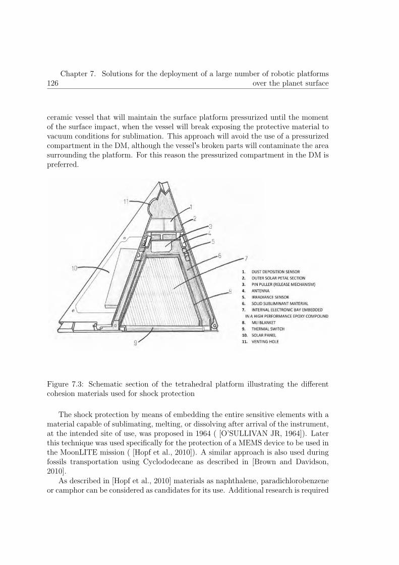
126Chapter 7. Solutions for the deployment of a large number of robotic platforms
over the planet surface
ceramic vessel that will maintain the surface platform pressurized until the momentof the surface impact, when the vessel will break exposing the protective material tovacuum conditions for sublimation. This approach will avoid the use of a pressurizedcompartment in the DM, although the vessel�s broken parts will contaminate the areasurrounding the platform. For this reason the pressurized compartment in the DM ispreferred.
Figure 7.3: Schematic section of the tetrahedral platform illustrating the differentcohesion materials used for shock protection
The shock protection by means of embedding the entire sensitive elements with amaterial capable of sublimating, melting, or dissolving after arrival of the instrument,at the intended site of use, was proposed in 1964 ( [O’SULLIVAN JR, 1964]). Laterthis technique was used specifically for the protection of a MEMS device to be used inthe MoonLITE mission ( [Hopf et al., 2010]). A similar approach is also used duringfossils transportation using Cyclododecane as described in [Brown and Davidson,2010].
As described in [Hopf et al., 2010] materials as naphthalene, paradichlorobenzeneor camphor can be considered as candidates for its use. Additional research is required

7.2. Platform deployment: solution conceived 127
to select or chemically synthetize the optimum material for its use in the platformproposed, although once developed it could be used in several space missions.
The tetrahedral platform has to be adapted to the use of these materials providingventing holes (refer to index 11 in figure 7.3) to facilitate the vapor removal from theplatform. Herein the protective material is aimed to cover a larger volume than inthe case proposed by [Hopf et al., 2010], thus a larger time for complete sublimationof the material shall be considered. Almost nearly two months (2 complete lunardays) has to be considered for a partial evaporation prior to open the solar panels.This would not be a problem as the platform could remain in a low hibernation statewaiting for the settlement of the dust ejected during the landing and the removal ofthe protective material (the impact of the platform and the penetrator will eject ahuge amount of dust at a height of kilometers ( [Gaier, 2005]). The thin protectivematerial layer that protecs the external solar panels will be the first in sublimate,thus alowing to generate the energy required to maintain the node in a hibernationstate up to the moment of solar panels deployment.
It is important to consider the residue that the protective material could leave overthe optics of the sensors after sublimation. To avoid any residue, the sensitive opticssurfaces will be covered with a thin layer of kapton prior to deposit the protectivematerial. During the solar panels deployment, the thin kapton films will be removedusing the descent movement of the solar panels connected with small wires to thekapton films. In this way the optics will be exposed to the environmental surface freefrom contamination.
The combination of the epoxy compound and the material that sublimates at lowpressure conditions permit a complete cohesion of the surface platform (the wholesurface platform will behave as a solid block). The proposed approach does not reducethe system operational capabilities and safeguard the integrity of the subsystemsduring the landing shock.
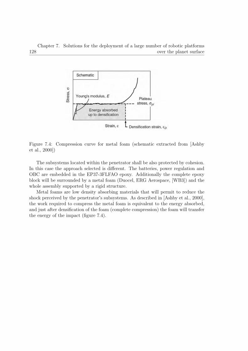
128Chapter 7. Solutions for the deployment of a large number of robotic platforms
over the planet surface
Figure 7.4: Compression curve for metal foam (schematic extracted from [Ashbyet al., 2000])
The subsystems located within the penetrator shall be also protected by cohesion.In this case the approach selected is different. The batteries, power regulation andOBC are embedded in the EP37-3FLFAO epoxy. Additionally the complete epoxyblock will be surrounded by a metal foam (Duocel, ERG Aerospace, [WB3]) and thewhole assembly supported by a rigid structure.
Metal foams are low density absorbing materials that will permit to reduce theshock perceived by the penetrator s subsystems. As described in [Ashby et al., 2000],the work required to compress the metal foam is equivalent to the energy absorbed,and just after densification of the foam (complete compression) the foam will transferthe energy of the impact (figure 7.4).

Chapter 8
Thermal design: conceivedtechnologies for thermal regulationof the exploration platform
129


8.1. Thermal design introduction and objectives 131
8.1 Thermal design introduction and objectives
At mid latitudes, the surface temperature of the Moon varies from around -180 �Cto +110�C (refer to section 6.5.2). Therefore, the surface platform should be ableto survive a thermal cycle of nearly 300 degrees of change approximately every 28Earth days (at mid latitudes, 1 lunar day is near 28 Earth days). This poses a realdesign challenge due to the difficulty of regulating thermally a small node having alow energy stored in extreme thermal conditions. For this reason a detailed thermalcontrol analysis and a custom thermal design is required to guarantee the node andits subsystems are maintained within safe temperature margins.
Therefore, the objective of the thermal control design is to prevent thatthe different subsystems of the platform could go over their operational andnon-operational temperature ranges during the different mission phases. Duringthe on-ground activities, lunch and space travel phases the platform is in anon-operational mode and its temperature is regulated by the carrier spacecraft.Once the node is deployed over the Moon surface, the platform shall be designedto withstand the thermal environment of the Moon. As described in chapter 7 ,during the platform deployment, the two bodies platform conceived are disjointed:the tetrahedron body reminds over the Moon surface, while the penetrator goes intode subsurface around 1 meter.
In section 9.1 it is described how the penetrator body will take the advantage ofthe lunar subsurface heat flux to maintain itself in a comfortable uniform temperaturearound -23 �C. Considering the good thermal contact between the penetrator and thelunar subsurface regolith it is possible to ensure that the penetrator will maintain themean temperature of the lunar regolith. The heat generated by the OBC during itsnormal operation (220 mW, refer to table 9.1) will be conducted thru the penetratorbody to the lunar regolith without a significant temperature growth. Consequently,the thermal control design shall be focused in the part of the platform that remainsover the surface of the Moon, as the aftbody of the platform will be subjected to thelunar surface temperature environment.
An additional objective is that the thermal mathematical model (or a simplifiedversion) could be used in the OBC of the platform operations over the planetsurface. In this way, the planning algorithm could work out the near future expectedtemperatures of the platform and schedule the tasks correspondingly, thus improvingthe efficiency of the system.
In section 8.3 the thermal design solutions proposed for this low mass andlow power consumption platform are described. Although to validate the thermalsolutions proposed it is necessary to use a thermal model. The thermal modelgenerated is presented in section 8.2.

132Chapter 8. Thermal design: conceived technologies for thermal regulation of the
exploration platform
8.2 Thermal Mathematical Model
8.2.1 The energy balance
As described previously, the TMM (Thermal Mathematical Model) shall verify thatthe platform subsystems are within the thermal limits of their operational andnon-operational temperature ranges, validating the thermal design. The commonapproach followed in spacecraft thermal design is to use a CAD model and a thermalanalysis software. The CAD model is discretised in nodes, the analysis parametersand constants introduced and the software tool performs the radiative and conductiveheat transfer calculations to obtain the temperature profiles of the different nodes. Inan iterative procedure of re-design and modelling is possible to optimise the thermaldesign of the spacecraft. Some commonly used software tools for this purpose areEsatan, Thermica Suite or Ansys thermal suite, between others. An example of thisthermal analysis can be found in [Nouvellon et al., 2012].
This procedure is not valid to accomplish the objectives of the TMM presentedin the previous section because the model cannot be exported to the OBC for its usein the planning algorithm. For this reason a custom TMM has been developed forthe thermal design of the platform. Additionally, this model directly, or a simplifiedversion, could be used in the OBC for planning purposes.
The Thermal Mathematical Model is based in the analysis of the total energybalance of the system under study and can be defined as:
dE
dt= Welect,net + Qcond,net + Qconv,net + Qrad,net (8.1)
Where Welect,net represents the electrical work flow, Qcond,net, Qconv,net and Qrad,net
represent the conductive, convective and radiative net heat fluxes respectively.Several assumptions will be considered for the TMM. How representative are these
assumptions with the real scenario will determinate the fidelity of the TMM. Theassumptions herein considered are necessary for generate a TMM representative ofthe system and that could be used by the OBC with a reasonable process effort.
� Complete vacuum conditions. No convective phenomena are considered in thestudy. This approximation fits very well with the actual conditions over theMoon�s surface where just small traces of gases are present (table 1.1). Theterm Qconv,net in the total energy balance can be neglected.
� The mass of the system under study is invariant. This assumption matchescorrectly with the actual platform behaviour, where there are not significantmass variations during the platform operation (there is not propellant flows asin spacecraft�s). It is not considered for the mathematical model the sublimation

8.2. Thermal Mathematical Model 133
of the shock protection material explained in chapter 7.2.3, as the sublimationprocess occurs before the operational phase of the platform.
� Any energy variation in the system can be related just with a temperaturechange or electrical energy variations, as the store of energy in the batteries,electrical work flow in the solar cells or electrical work dissipation in the platformsubsystems. Other energy variations as microwave electromagnetic inputs oroutputs related with the communication antennas or thermal energy stored inphase change of materials are neglected as their influence in the system understudy is marginal.
� Each isothermal node considered in the TMM is uniform in temperature (thereis not mass exchange between isothermal nodes but there is heat exchangebetween them).
� The field of view between the different isothermal nodes considered of theplatform is neglected. The platform isothermal nodes have been selected insuch a way the field of view between them is minimum.
� The thermal node considers radiation phenomena, for this reason the Kelvindegrees unit is used in the TMM (non-linear relations involve in the TMM).
Therefore, considering these assumptions the total energy balance equation canbe split into an electrical energy balance and a thermal energy balance as following:
VdQelect
dt= Welect,in − Welect,out − Welect,dis (8.2)
CdT
dt= Qcond,net + Qrad,net + Welect,dis (8.3)
Where Welect,in is the work flow generated by the solar panels and thermoelectricgenerator, Welect,out is the electrical work flow within the electrical subsystems andWelect,dis is the dissipated electrical power. The Electrical balance is studied in chapter9 as part of the energy balance. The thermal energy balance is the balance that willrule the TMM.
The radiative net heat flux (Qcond,net) can be expressed as the difference betweenthe radiative heat flux that enters in the platform and the radiative heat flux that isradiated from the platform:
Qrad,net = Qrad,in − Qrad,out (8.4)
Qrad,in = α· I·A+ Qplanet,in (8.5)

134Chapter 8. Thermal design: conceived technologies for thermal regulation of the
exploration platform
Qplanet,in = αb·Ab·Fb,p· εp· σ·T 4p (8.6)
Qrad,out = ε·A· σ· (T 4hot − T 4
cold) (8.7)
Where α is the dimensionless absorptance defined as the fraction of incidentelectromagnetic power that is absorbed at an interface. I represents the solarirradiance ( W
m2 ) received at the surface area (A) of interest. I value can be obtainedusing the algorithm developed and described in section 6.4.2. ε is the emissivity,a dimensionless quantity dependent of the material properties and represents theeffectiveness of the surface under study in emitting energy as thermal radiation. σis the Stefan-Boltzmann constant 5.670373· 10−8 W
m−2 ·K−4 and Thot and Tcold are thetemperature (in K) of the radiant surface and cold body respectively. The last termcontemplated in the thermal balance is the thermal radiation emission from the moonsurface.This term relates the energy received by the platform from the planet surfacedue to the IR emission of the planet. αb Ab are the area and absorptance of theplatform while εp and Tp are the emissivity and temperature of the planet surface.The term Fb,p is the field of view factor from body surface to planet surface. Inthe nominal configuration of the platform (planar Moon surface) this factor can beconsidered as near cero, neglecting the influence of the planet emission. Neverthelessthe planet thermal radiation shall be considered if the platform is deployed in aninclined plane, in a crater or near mountains.
The conductive net flux for a two isothermal nodes, considering an ideal thermalcontact by an area (A) and a material of thermal conductivity K1,2 separated adistance d1,2 can be expressed as:
Qcond,net = Qcond1,2 = k12· A· (T1 − T2)
d1−2
= −Qcond2,1 = −k12· A· (T2 − T1)
d1−2
(8.8)
The radiative net heat flux in a solar cell is slightly different from the standardterms previously presented. For a solar cell:
Qrad,out = ε·A· σ·T 4solarcell (8.9)
Qrad,in = (α· η·Fpg)· I·A (8.10)
Where Qrad,out is the same as the previous terms presented but the Qrad,in termtakes into consideration the energy absorbed by the solar cell that is transformedin electrical work and not in heat (WB2). η is a dimensionless term representingthe solar cell efficiency, defined as the ratio between the maximum electrical power

8.2. Thermal Mathematical Model 135
produced by the solar cell at 25�C with respect to the input irradiance of the area. Fpg
is a dimensionless packaging factor considering the non-active area of a solar paneldue to the packaging of the different solar cells that conforms the solar panel.
8.2.2 Platform multi-node discretization
The node has been discretized in isothermal nodes as described in figure 8.1.
Figure 8.1: Isothermal nodes selection for the platform thermal model
During the node discretization of the platform the following considerations havebeen applied.
� Minimum number of nodes. Increase the number of nodes will increase thethermal accuracy of the TMM, although it will also increase the processingeffort to resolve by analytical methods the TMM.
� The field of view between isothermal nodes shall be highly reduced. In this wayit would be possible to simplify the TMM because radiation relations betweennodes can be neglected.

136Chapter 8. Thermal design: conceived technologies for thermal regulation of the
exploration platform
� The temperatures obtained in each node shall be enough for the objectives ofthe TMM.
The isothermal node 2 represents the deep space temperature (2,7 K) and theisothermal node 3 is the Moon�s surface temperature that can be obtained using themathematical model developed and described in section 6.5.2.
The nodal equations for each node of the platform can be obtained from thedifferent terms presented previously as:
Ci· T+i − Ti
Δt=
N∑j=0
Qij
= Qelect,disi + Qplanet,ini+ Qradsolar,ini
− Qradspace,outi +∑j=1j �=i
Qcond,ij +∑j=1j �=i
Qrad,ij
(8.11)
Euler discretization of time (Δt) has been applied with the objective of solve themodel using numerical solution methods. The overall thermal capacity Ci is the sumof the mass and heat capacity product of each of the elements that compose theisothermal node i :
Ci =n∑
i=1
mi· ci (8.12)
With the objective of summarize the thermal couplings between the differentisothermal nodes presented in figure 39, a thermal coupling node matrix has beendeveloped and is presented in table 8.1. In this matrix the radiative couplings betweennodes are situated in the upper triangular part of the matrix, the conductive couplingsin the lower triangular part and the thermal capacities of each node in the diagonal.
Several parameters related to the different materials used in the platform areinvolved in the TMM developed. These parameters usually vary considerablydepending on the source consulted, the specific material used, manufacturer ortemperature of operation. A search has been performed in the literature to use theparameters values that better fit the materials to be used in the platform. Table 8.2describes the parameters and the values used.
The thermal coupling between node 1 and node 4 (C14 in Table 7) correspond tothe conductive flux thru the thermal switch. This element has been included in thethermal model as two thermal contacts in parallel dependent of the temperature. Thethermal contacts have been modeled as two thermal resistors in parallel (figure 8.2).The thermal resistance denominated as Rsupport models the thermal contact between

8.2. Thermal Mathematical Model 137
Nodei/j
1 2 3 4 5 6 7 8 9 10
1 C1 R12 - - - - - - - -2 - - - - R25 R26 R27 R28 R29 R210
3 C13 - - - - - - - - -4 C14 - C4 - - - - - -5 C15 - - - C5 - - - - -6 C16 - - - – C6 - - - -7 C17 - - - - - C7 - - -8 C18 - - - - - - C8 - -9 C19 - - - - - - - C9 -10 C110 - - - - - - - - C10
Table 8.1: Platform thermal coupling node matrix
node 1 and 4 corresponding to the auxiliary pieces that supports the thermal switchbetween the inner electronics bay and the external structure. These elements havebeen manufactured in PTFE to reduce their thermal conductance. This thermalresistance is always present, independent of the temperature or if the switch is closedor open. The thermal resistance denominated as Rcontact models the thermal contactof the thermal switch when it is closed and when it is open. This thermal contact(aluminum) varies the contact area in function of the temperature. The transitiontemperature of the thermal switch from hot to cold is 10 �C; correspondingly thetemperature transition from cold to hot is 20�C. This typical hysteresis of the SMAmaterials is very useful in this application because avoids any possible mechanicaloscillation during the hot-cold and cold-hot transitions.

138Chapter 8. Thermal design: conceived technologies for thermal regulation of the
exploration platform
Parameter Symbol Value Units SourceStefan-Boltzmann
constantσ 5.670373· 10−8 W
m−2·K−4 N/A
7075 aluminumalloy emissivity
εaluminum 0.82 - Kauder 2005
7075 aluminumalloy absorptance
αaluminum 0.68 - Kauder 2005
7075 aluminumalloy Specific heat
caluminum 0.91 Jg·K [WB6]
7075 aluminumalloy density
ρaluminum 2.81· 106 gm3 [WB6]
7075 aluminum alloyThermal conductivity
kaluminum 205 WK·m [WB6]
Solar cell absorptance αsolar cell 0.92 - [Spectrolab, 2010]Solar cell emissivity εsolar cell 0.85 - [Spectrolab, 2010]
Solar cell efficiency η 0.283 -Edmondson
2006Solar panel packaging
factorFpg 1.8 - [WB2]
Solar cell Thermalconductivity
ksolar cell 148 WK·m
Armstrong2010
PV cellSpecific heat
csolar cell 0.67 Jg·K
Armstrong2010
Solar cell density ρsolar cell 2.33· 106 gm3
Armstrong2010
Thermal conductivityregolith
kregolith
9.3· 10−3
(compacted regolithby the platform)
WK·m
Vasavada1999
Regolith depth Lregolith 0.02 mLangseth1976
FR4 thermalconductivity
KFR4 0.25 WK·m
Vanek2014
FR4 Specific heat cFR4 0.84 Jg·K Vanek 2014
FR4 density ρFR4 1.85· 106 gm3 [Mangroli et al., 2011]
PTFE Thermalconductivity
KPTFE 0.25 WK·m [Dupon, 1996]
Table 8.2: Parameters used in the Thermal Mathematical Model

8.3. Thermal design solutions and model results 139
Figure 8.2: Thermal switch model
8.3 Thermal design solutions and model results
The operational strategy considered in order to handle the extremely lowtemperatures during the lunar nights is hibernation of the tetrahedral platform (theOBC and main batteries located in the penetrator remains operative). The surfaceplatform will be able to obtain scientific data during the entire lunar day and duringthe first days of the lunar night. As later explained in chapter 9, the penetrator�ssubsystems remains operational, in a low consumption mode, during all the nightthanks to the comfortable temperature beneath the lunar surface (around -23�C). Anight energy harvesting system permits to obtain energy to charge the main batteriesand perform punctual scientific measurements during the night. The adopted thermaldesign will permit to efficiently use the energy harvested, during the lunar day andalso during the night, to heat up the inner bay of the tetrahedral platform to reach theoperational temperature range and perform punctual scientific measurements duringthe cold nights.
The platform elements disposition has been designed in order to optimize thethermal regulation of the node. With the objective to increase as much as possiblethe operational time of the node during the lunar nights the thermal design includesthe following concepts:
1. All the platform elements are able to survive in a non-operational mode from -40�C to -373�C without major damages. This implies special considerations in allthe electronics, electrical and mechanics elements of the node (e.g. mechanicalexpansions and contractions of all the node elements).
2. A highly thermally isolated electronic bay situated in the inner part of thesurface platform will be the key element of the thermal design. The inner

140Chapter 8. Thermal design: conceived technologies for thermal regulation of the
exploration platform
Figure 8.3: SMA based thermalswitch (7mm in height and 111mm in diameter).
bay will be in contact with the external structure of the tetrahedral platformjust at the base. A Multi-Layer Insulation (MLI) sheet covers the completeinner bay except of its base. In the base a thermal switch will be in chargeof controlling the heat transfer by the thermal conduction between the innerbay and the external structure. This automatic reconfigurable hardware basedon SMA technology will regulate the temperature of the electronics bay as afunction of the external temperature on the Moon surface. The thermal switch(figure 8.3) will isolate the electronics bay during the cold nights and will putit in thermal contact with the Moon surface during the hot days. The thermalswitch is completely passive (0 W) and its total mass is below 120g. The thermalswitch operation is based on an SMA fiber in counterforce with a spring. Whenheated above its temperature transition the SMA will apply a force higher thanthe spring, generating a rotational movement that would put in thermal contactthe top part of the switch with the bottom part. In this way the heat couldgo thru the thermal switch. Below the temperature of transition of the SMAmaterial, the spring will make the switch open, avoiding a good thermal contactbetween the up and bottom parts of the thermal switch, thus isolating the innerbay of the platform.
3. Active heaters will be used to heat-up the inner bay to warm it up to-90�C (183,15K). The -90�C limitation is imposed by the minimum operationaltemperature range of the electronics. The node includes 8 housekeepingtemperature sensors that monitor the temperature of the different subsystemsto achieve a closed loop thermal control.
4. As described in chapter 7 the electronics situated in the inner bay is embedded ina thermal conductive epoxy. This will be not helpful only for shock protection;additionally this epoxy permits to homogenize the temperature of the inner bay.

8.3. Thermal design solutions and model results 141
The heat generated by the heaters and the own electronics power dissipationwill be diffused by the epoxy. Moreover, the heat capacity of the inner bayblock is increased. In return the use of this epoxy would mean an importantmass penalty for the platform (around 400 grams).
5. A MLI (Multi Layer Insulation) blanket composed of 40 goldized Kapton layerscovering the inner bay epoxy block reduce the heat losses by radiation betweenthe inner bay and the external platform structure.
6. The external aluminum structure will be used as radiators to radiate the heat tothe outer space during the hot days. During the lunar days the thermal switchkeeps the inner bay in thermal contact with the external structure. Coatingpaints will be used to regulate the emissivity of the structure in order to ensurethat the node does not heat over +150�C (the upper limit temperature imposedby the electronics and batteries). Additionally the heat loss to the planet surfaceby the node base has to be considered.
Using the mathematical model including all the thermal design consideration listedabove an iterative design procedure was accomplished with the objective of optimizethe thermal design. The final results obtained are described below.
Figure 8.4 presents the model results for the temperature evolution of the thermalnodes of the platform (as defined in figure 8.1) considering the aftbody platform isinactive (0 W dissipation in the electronics bay). The model results correspond to600 hours (25 days) starting the 5/1/1972 with the platform located in the Moonequator.

142Chapter 8. Thermal design: conceived technologies for thermal regulation of the
exploration platform
Figure 8.4: Thermal nodes temperature evolution during approximately 1 lunar dayconsidering 0W dissipation.
As expected the node structure follows the temperature profile of the Moonsurface. As there is not power dissipation within the electronics bay, its temperatureremains stable at the same temperature than the external structure. The temperaturevariations between the different solar cells (nodes 5,6,7,8,9 and 10) depend directlyon the sun position w.r.t the platform orientation. If the sun illuminates the solar cellits temperature will increase significantly, and consequently, solar cells in shadow willdecrease its temperature. The area illuminated in each moment for each solar celldirectly depends on the platform orientation with respect to the Sun and the solarincident angle. The solar incident angle is obtained from the mathematical modeldeveloped in chapter 6.4.2 and the platform orientation (ϑ) w.r.t the lunar equatoris an input for the mathematical model. With these two parameters it is possibleuse geometrical relations to discretize the solar area illuminated. These geometricalrelations have been introduced in the TMM. As the thermal conductivity of the solarcells with the external structure is driven by the low thermal conductivity of the FR4material that supports the solar cells, the temperature changes can be appreciated inthe figure for the different solar cells as they become illuminated or non-illuminated.In figures 8.4, 8.5 and 8.6 a sharpen transition in the temperature evolution of the
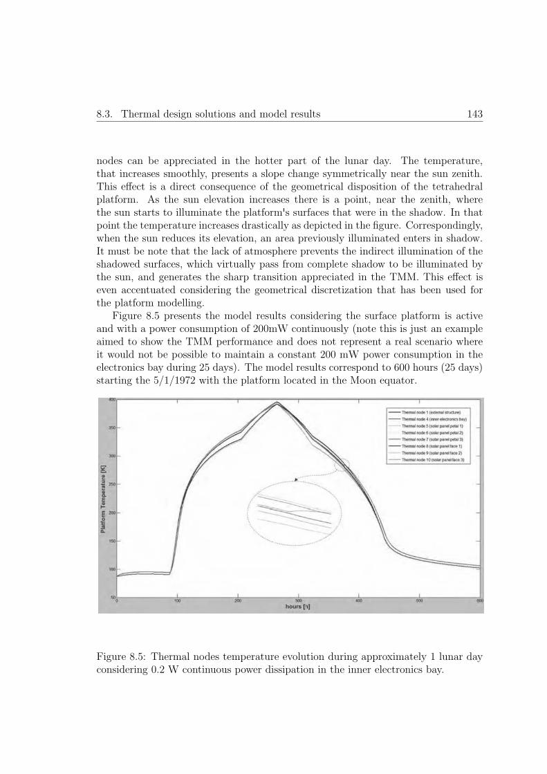
8.3. Thermal design solutions and model results 143
nodes can be appreciated in the hotter part of the lunar day. The temperature,that increases smoothly, presents a slope change symmetrically near the sun zenith.This effect is a direct consequence of the geometrical disposition of the tetrahedralplatform. As the sun elevation increases there is a point, near the zenith, wherethe sun starts to illuminate the platform s surfaces that were in the shadow. In thatpoint the temperature increases drastically as depicted in the figure. Correspondingly,when the sun reduces its elevation, an area previously illuminated enters in shadow.It must be note that the lack of atmosphere prevents the indirect illumination of theshadowed surfaces, which virtually pass from complete shadow to be illuminated bythe sun, and generates the sharp transition appreciated in the TMM. This effect iseven accentuated considering the geometrical discretization that has been used forthe platform modelling.
Figure 8.5 presents the model results considering the surface platform is activeand with a power consumption of 200mW continuously (note this is just an exampleaimed to show the TMM performance and does not represent a real scenario whereit would not be possible to maintain a constant 200 mW power consumption in theelectronics bay during 25 days). The model results correspond to 600 hours (25 days)starting the 5/1/1972 with the platform located in the Moon equator.
Figure 8.5: Thermal nodes temperature evolution during approximately 1 lunar dayconsidering 0.2 W continuous power dissipation in the inner electronics bay.

144Chapter 8. Thermal design: conceived technologies for thermal regulation of the
exploration platform
As it can be appreciated the inner electronics bay (red line) is always around 4degrees up w.r.t the rest of the structure during the night. During the day, the sun isheating up the external elements of the structure and therefore they are hotter thanthe inner bay that just is dissipating 200mW. The effect of the thermal switch canbe clearly seen in figure 8.5 (zoom detail). As the platform get colder during thelunar evening the SMA material installed in the thermal switch relaxes, consequentlyopening the thermal switch and reducing the thermal heat transfer between the innerelectronics bay and the external structure. As a consequence of this, and consideringthe 200 mW continuous power dissipation within the inner bay, its temperatureincreases up to the equilibrium state, nearly 4 degrees up w.r.t the external structurenode.
Figure 8.6 presents the model results considering there is need of performingscientific measurements during the night. In order to perform scientific measurementsduring the night, it is required to heat up the inner bay up to -90�C, that is consideredthe minimum operational temperature of the platform. As shown in figure 8.6, it isrequired as a minimum 2W during 10 hours to increase the inner electronics baytemperature to -90�C (193.15K). This is possible thanks to the thermal isolationprovided by the thermal switch as previously described. The model results correspondto 600 hours (25 days) starting the 5/1/1972 with the platform located in the Moonequator.

8.3. Thermal design solutions and model results 145
Figure 8.6: Thermal nodes temperature evolution during approximately 1 lunar dayconsidering 2 W power dissipation during 10 hours in the inner electronics bay for apunctual measurement during the lunar night.


Chapter 9
Energy management andinnovative concepts for energyharvesting.
147

9.1. Energy harvesting for space exploration 149
9.1 Energy harvesting for space exploration
Reviewing the state of the art of similar space exploration platforms to the one hereinproposed (refer to chapter 4 and comparative table 4.1), we can immediately realisethat just a few proposals (as MetNet mission), considered solar panels for energyharvesting, and none of them considers energy harvesting systems during the night.The main reason is the complexity to fix the technical requirements mandatory forharvesting efficiently energy over the planet surface within a small and low weightplatform.
In this chapter, different techniques for energy harvesting over the Moon surface,compatible with the platform conceived, are proposed. The use of these techniqueswill permit to extend the mission lifetime, thus permitting a long term WSNmonitoring scenario that drastically increase the scientific mission returns, makingthe mission concept proposed a serious alternative to traditional mission concepts asbig rovers or landers.
Energy harvesting has become of growing interest in the last years and the numberof research reports has kept increasing for the last decade ( [Harb, 2011]). The conceptidea is to include in the device to be powered a subsystem able to harvest smallamounts of energy from the environment and use the generated energy to maintain thesystem powered without the need of wires, fuel or maintenance. The increasing use ofWSN made the need of improve these harvesting techniques and make them suitableto power the autonomous nodes in a WSN, with a power consumption normallybelow the 100μW . In these commercial systems the combination of the harvestingtechniques with a rechargeable battery or super capacitor makes feasible the energyautonomy of the WSN during its operational lifetime.
The sources of energy for harvesting used in the state of the art of energyharvesting techniques are very diverse: mechanical energy from vibration or motion,electromagnetic, thermal, momentum generated by radioactive reactions, pressuregradients, magnetic, liquids flow, solar, light or biological.
In the field of space exploration, and as commented in section 1.2, the RadioisotopeThermoelectric Generators (RTGs) or fuel tanks are commonly used as primaryenergy source. Usually, as auxiliary energy source, solar energy harvesting usingsolar cells are the more common harvesting technique used in conventional spaceexploration. For small exploration platforms, as those described in the state of theart in chapter 4 , the most common solution proposed is the use of batteries asprimary energy source. Hence, the batteries are charged before the separation of theplatform from the transport vehicle and used during the timeframe mission. Once thebatteries are completely depleted the mission ends, even if the systems are completelyoperational. Obviously, following this approximation the mission lifetime is highlyreduced and, even with low power consumption considerations, the mission lifetime

150 Chapter 9. Energy management and innovative concepts for energy harvesting.
usually cannot overpass one year (in some cases just a few hours).In this work we propose to completely substitute the non-renewable energy sources
with energy harvesting techniques aimed to power the nodes, continuously rechargingthe batteries and extending the lifespan of the mission during years.
The energy harvesting for space exploration WSNs presents additional problemsto those ones presented in commercial WSNs for terrestrial applications. Even thoughusing low power consumption technologies as those proposed in this thesis, the energyrequirements of each of the nodes of the WSN in an extraterrestrial environment aremuch higher than those equivalents in a terrestrial application. The main reasonsare:
� The extreme environmental conditions in which the proposed WSN node shallwork (temperature operation range, radiation, dust, etc.). Active thermalregulation shall be considered for operation in extremely low temperatures.
� Complex payloads and mechanisms with elevated punctual power consumptions.
� Additionally, the WSN deployed over an outer space planet shall workduring the mission lifespan without maintenance, what implies redundancyand high reliability electronics components what usually implies higher powerconsumption.
Finally, we have to consider an efficient energy conditioning for its final used inthe platform. If the energy source is dependent of environmental conditions energystorage shall be considered. Energy storage using batteries is a well fitted solution.It is important to ensure proper working voltage and current levels in order toensure an efficient battery charging and discharging processes. Other possibility,also proposed in this thesis, is the use of the energy harvested directly for its finaluse, for example thermal energy in order to maintain warm certain elements of theplatform as later explained. This is the most efficient method as there is not energytransformation involved.
In the following chapters, an analysis of the power consumption requirements ofthe platforms and the energy management philosophy is introduced. Afterwards,energy harvesting solutions proposed are described.
9.2 Energy management and energy consumption
mathematical model
To reduce the power consumption of the exploration platform is not only possibleby reducing the individual power consumption of its subsystems; a smart energy

9.2. Energy management and energy consumption mathematical model 151
management will play an important role in this objective.From the point of view of energy management we can consider two general
operational modes:
� Continuous operation: if the energy harvesting system is able to obtain andstorage the energy required for continuous operation (mean power consumptionof the platform is lower than the mean power harvested). The energymanagement is reduced to sequence the platform operational activities in sucha way the batteries are not depleted in any moment. This operational mode isnot feasible in the Moon scenario, were during the long nights the main powerharvesting technique is not available (solar energy).
� Discontinuous operation: in this case, the node mean power consumptionis higher than the average harvested power, thus the node shall operateintermittently.
The discontinuous operational mode can be addressed just following apredetermined sequence of activities. One of those activities could be enter in ahibernation state with the objective of reduce to a minimun the power consumption.In the Moon scenario, and considering the platform herein proposed, this would meanthat during the lunar day the node will be near to a continuous operation mode.During the night the node shall be able to perform previously scheduled punctualactivities and enter in an hiberation state. This would permit at least to obtain somepunctual environmental measurements during the long nights that could be of mainimportance for certain scientific objectives.
In order to permit the platform to optimize its operational time, including nightenvironmental monitoring, the platform shall be able of planning its activities infunction not only of the energy available, but also in function of the future energyavailable. In chapter 10 a high level control architecture is proposed for this platform.
Therefore, the energy management of the platform is based in a discontinuousoperational mode with the following approach:
1. Two set of batteries store the energy harvested: (i) the surface platform batterieswill be operative during the lunar days and they will be used to power thescientific payload and the radio interface system; (ii) The principal batteries,located in the penetrator body and beneath the planet surface, will be able toprovide energy continuously; generally to the OBC and sporadically to heat upand power the tetrahedron platform for night operation.
2. The OBC will plan the operation sequence of the platform considering theenergy available and the expected harvested energy in the following hours ordays.

152 Chapter 9. Energy management and innovative concepts for energy harvesting.
3. In case the energy available is not enough to perform the activities plannedor even if there is not enough energy to re-planning, the node will enter in aultra-low power consumption mode waiting for energy availability.
This energy management approach is based in a nominal node platform; in case ofan operational malfunction of any of the subsystems, redundant operational modesare described in section 5.5.
SubsystemNominal powerconsumption
[mW]
Idle powerconsumption
[mW]
Nominaloperation
time[ms]
Energy[mJ]
Temperaturesensors (x3)
2.175* (PT ) 0 34 (τT ) 0.07395*
Irradiancesensor (x9)
0** 0 72 (τI) 0**
TIDmeasurement
57 (PTID) 0 18 (τTID) 1.026
SEUsmeasurement
21(PSEU) 0 3· 104(τSEU) 630
DDSmeasurement
8*(PDDS) 0 80 (τDDS) 0.64*
DDScalibration
9000***(PCAL) 0 3000 τCAL) 27000***
Housekeeping(x8)
5.8*(PHSK) 0 90 τHSK) 0.522*
Acquisitionelectronics
110(PACQ) 0Depends on planning
(τACQ)Depends
on planningOBC
general operations100(POBC)
4.558(PIOBC)
Depends on planning(τOBC)
Depends onplanning
OBCplanning operation
200 duringplanning algorithmimplementation
(PIPLN)
0 (PIPLN) TBD
Commsmodule
800(PICOM) 0Depends on planning
(τCOM)Depends
on planning
Powermodule
75 (batteries indischarging mode;not charging modepower consumtion
considered)(PIPWR)
7.5(PIPWR)Depends on planning
(τPWR)Power losses due to normal power operation.
Depends on planning.
Heaters 5000(PIHTR) 0Depends on planning
(τHTR)Depends
on planning* Not considering the acquisition electronics power consumption considered in the Acquisition electronics subsystem** The photodiodes are passive (the light incident generates the photocurrent used for illumination measurement). The acquisition electronics is not considered.*** Nominal at 25�C. Operation time changes in function of the environmental temperature
Table 9.1: Platform subsystems power consumption estimation
The mathematical environmental models herein developed and described insection 6.4.2 (solar irradiance model), 6.5.2 (surface temperature model) and 8.2(node platform thermal model) will help the planning algorithm to predict the energythat could be harvested. However, the algorithm will require the energy consumptionmodel of the platform to compute the optimal sequence of activities in function ofthe power available, the future power available and the consumption of each potentialtask to be performed.
Table 9.1 presents the estimated power consumption of each subsystem of theplatform that will be required to define the energy consumption model. Deploymentmechanism power consumption is not considered in table 9.1 because it is operated

9.3. Solutions proposed for energy harvesting 153
once at the beginning of operation activities using the external solar panels, whichare no longer used during the mission. For details on solar panels deployment systemrefer to section 5.2.4. The power consumption estimations presented in table 9.1 arenominal power consumption values obtained theoretically and experimentally. Theexperimental power consumption values were obtained from the prototype subsystemsdeveloped and described in chapter 10.5. In order to consider a more realistic scenariowe shall derate the values estimated considering aging factors, temperature variationand reliability coefficients. Herein a general derating factor (η) of 0.5 is considered,although a specific derating factor analysis (theoretical and experimental) shall beperformed for each subsystem (the analysis shall be perform considering the spacequalified design of the subsystems herein proposed).
Task EquationSurface Temperature
measurementTTMP = (τT ·PT + PACQ· τT + PPWR· τT )· η
Irradiance measurement EI = (τI ·PI + PACQ· τI + PPWR· τI)· ηTID measurement ETID = (τTID·PTID + PACQ· τTID + PPWR· τTID)· ηSEU measurement ESEU = (τSEU ·PSEU + PACQ· τSEU + PPWR· τSEU)· η
Tetrahedral platformactive heating
EHTR = (τHTR·PHTR + PPWR· τHTR)· η= minner bay· cinner bay· Tend−Tstart
τHTR
DDS calibration ECAL = (τCAL·PCAL + PACQ· τCAL + PPWR· τCAL)· ηDDS measurement EDDS = (τDDS·PDDS + PACQ· τDDS + PPWR· τDDS)· η
Hibernation ESLP = (τSLP ·PIOBC + τSLP ·PIPWR)· ηHousekeeping measurement EHSK = (τHSK ·PHSK + PHSK · τHSK + PPWR· τHSK)· η
Radio interfacecommunication
ECOM = (τCOM ·PCOM + PPWR· τCOM)· ηPlanning EPLN = (τPLN ·PPLN + PPWR· τPLN)· ηTable 9.2: Energy consumption mathematical model equations
The energy consumption equations have been established in function of each task.A task is herein defined as a set of operations in which each one requires the use ofa subset of the different subsystems presented in table 9.1. Table 9.2 resumes theequations that define the energy consumption of the platform.
9.3 Solutions proposed for energy harvesting
The energy harvesting techniques proposed are in direct relation with the platformconfiguration (section 5.1) and the deployment technique (chapter 7 ). As depictedin figure 9.1 three different techniques are conceived.

154 Chapter 9. Energy management and innovative concepts for energy harvesting.
Figure 9.1: Overview of the harvesting techniques conceived for the platform
Solar energy using solar cells is foreseen as the major energy source. The long (andobviously always sunny) days over the Moon surface will provide a great amount ofenergy for the small platform (refer to the work-out values of W
m2 in figure 6.10).The faces and petals of the tetrahedron platform are covered with solar cells, thusproviding the means to transform the solar irradiance in electrical energy, that will bestored in the primary and auxiliary batteries of the platform. However, this energystored will be lost when the temperatures over the Moon surface descend during thelong and cold nights. Even the most advanced Lithium batteries under development atNASA auspices could not go below -60 C ( [Bugga et al., 2007]). In the configurationconceived the batteries would start to be inoperative to maintain a nominal functionof the electronics subsystems around -40 C. Herein it is proposed, as second methodfor energy harvesting, to use the heat flux of the subsurface to maintain the batteriesat a constant temperature around -23 C.
Finally the third method for energy harvesting is to use the temperature differencebetween the surface and the subsurface to, using a Thermoelectric Generator, generatea small quantity of energy in form of electrical current that will charge the subsurfacebatteries during the cold nights.

9.3. Solutions proposed for energy harvesting 155
9.3.1 Energy harvesting for space exploration
The Moon is a small planetary body, and there is good reason to believe that it haslost most of its initial heat during its 4.6-b.y. history. Most of the present heat flux isprobably generated by radioisotopes (mainly 40K, 232Th, 235U, and 238U) presentin the interior to a depth of about 300 km ( [Heiken et al., 1991] after [Langseth et al.,1976]). This heat flow was measured experimentally during the Apollo missions 15and 17 and the equilibrium temperature of the lunar regolith measured was about254 K at the Apollo 15 landing site whose latitude is 26.13 N, and about 258 K atthe Apollo 17 landing site at latitude of 20.19 N ( [Ran and Wang, 2014]). Figure9.2 shows the temperature increase in function of the depth using the revised dataobtained during the Apollo missions ( [Langseth et al., 1976]).
Figure 9.2: Mean substrate temperature at the four probes from the Apollo missionsin function of depth (extracted from [Langseth et al., 1976]).
Following the results obtained from [Ran and Wang, 2014] and the measurementsobtained during the Apollo missions ( [Langseth et al., 1976]) it can be stablished,for mean latitudes, an equilibrium temperature of approximately 250 K at a depth of1 m. Actually as shown in figure figure 9.2, at a depth of 200 cm this temperature isalready reached.
This constant temperature will be used to maintain the OBC and the batteriesat a constant temperature within their operative range of the batteries. As describedin chapter 7 the estimated depth reached by the penetrator part of the platform willbe between 0.3 to 1.2 meters, pending on factors as penetration angle and materials

156 Chapter 9. Energy management and innovative concepts for energy harvesting.
present in the lunar regolith. As shown in figure 9.2, even in the worst case estimation,it would be possible to use the thermal heat of the Moon�s subsurface to maintainthe batteries and the OBC operative during the lunar nights.
9.3.2 Thermoelectric generator
Innovative custom Thermoelectric Generator design
During the cold nights, the energy stored in the batteries located within thepenetrator will permit the OBC to be operative. As previously described, the nodewill be in a hibernation state most of the time and perform sporadic measurementsin function of the available energy. With the objective of increasing the number ofmeasurements during the nights, and in this way increase the scientific data return ofthe mission, an alternative energy source during the night shall be considered. Hereinit is proposed the use of the temperature difference between the lunar surface and thelunar sub-surface during the nights, in order to harvest a small but constant amountof energy that will permit to increase the platform activities during the lunar nights.
Electrical energy can be obtained from thermal energy by thermoelectric orpyroelectric transducers. The main difference is that the pyroelectric transducer usesthe temperature variations in time to generate an electrical power while thermoelectricprinciple is based on temperature variation in space.
Thermoelectric Generators (TEG) are commercially available as slim devices(3-5 mm in height) with a large surface area for heat exchange as shown in figure9.3. These optimized devices are able to obtain several watts of power with anefficiency typically around 5%. Practical devices are made of multiple pairs of p-typeand n-type semiconductor legs (thermocouples). The Seebeck effect ( [Shakouri,2011]) is the principle of working of TEG. For each material, the cooling effectis gauged by the Peltier coefficient Π that relates the heat carried by the chargesto the electrical current through Q = Π· I. The power generation is measured bythe Seebeck coefficient α, which relates the voltage generated to the temperaturedifference through V = n· (α1· (Th − Tc) + α2· (Th − Tc)
2). Using several elementselectrically in series and thermally in parallel the operating voltage is increased, whilereducing its electric current. Such an arrangement minimizes parasitic losses in theseries electrical resistance of the wires and interconnects. The thermocouples areconnected in series using an electrical shunt thermally in contact with a ceramicsubstrate that is used as insulator. Both ceramic surfaces in each side of the TEGcan be put in thermal contact with the hot and cold sources (heat exchangers arefrequently used to increase the heat exchange efficiency).

9.3. Solutions proposed for energy harvesting 157
Figure 9.3: Commercial thermoelectric generator system from Marlow Industries ([Marlow Industries, 2015], model XLT6-4-01LS) (left) and schematic section of aTEG (right), extracted from [LeBlanc, 2014].
Commercially available TEG cannot be used in the proposed platform directly.The heat and cold sources are separated several hundred of centimeters. A traditionalway to solve this problem is the use of heat pipes to transfer the heat from the heatsource to the cold side. Usually this heat pipes use liquids to improve the heat transferefficiency. The use of such devices would represent an important challenge at verylow temperatures (100K) and also they would increase the mass and complexity ofthe platform. Also we should consider a reliability reduction because of the difficultyof protect the heat pipe system from the high level shock during the landing.
Another approach proposed by [Lorenz, 2003], is to use the penetrator body toconduct the heat and use commercial TEG with heatsinks to capture some energyflowing through the subsurface due to diurnal heating by Sunlight. This interestingapproach was found not compatible for the platform proposed as the penetrator bodywill be situated several cm below the surface where the heat flow is drastically reduced(figure 9.3). Additionally the concept proposed by [Lorenz, 2003], uses the nearsurface heat change during the diurnal cycle, while in the application herein proposedthe interest is to obtain energy during the night and far from the surface. Anotherimportant drawback of using this technique is that commercial TEG use ceramicplates that are fragile and not suitable for hard landing applications.
The TEG proposed in this thesis is based in a simple bundle of wires.Robust, extremely cheap and flexible, this TEG can extract small amounts ofenergy continuously during the lunar night thus charging the batteries for punctual

158 Chapter 9. Energy management and innovative concepts for energy harvesting.
experiments during the cold nights.In the TEG construction herein proposed the length of the two dissimilar
semiconductors will increase drastically with respect to the commercial TEG devices,thus changing the TEG construction completely. As the minimum distance requiredto obtain the maximum temperature difference is 200 mm (refer to section 9.3.1) thefollowing design approaches have been followed:
� The P and N semiconductors bars are substituted by two dissimilar metal wires.Even though the semiconductors present larger Seebeck coefficients than metals,the concept proposed requires wires to cover the distance between the hot sideand cold side. Several wires of two dissimilar metal conductors will be connectedin series and parallel following a custom configuration. The wire metals selectedshall be able to support elevated tensile forces and be available commerciallyas wires. The selection of the TEG materials shall be based in the followingconsiderations:
– New semiconductor elements have been developed for the TEG industry,increasing the Seebeck coefficient of metals two order of magnitudeand new developments promises even higher values ( [LeBlanc, 2014]).Unfortunately, these semiconductors cannot be fabricated easily inthe form of thin and robust wires. This is the main reason whycommercial thermocouples used for remote temperature monitoring arealways metallic.
– Low resistivity of the materials selected will improve the TEG efficiency.
– The operation temperature of the TEG drastically affects the Seebeckcoefficient. The thermocouple materials used in the TEG proposed shallbe compatible with low temperature application (100 K).The materialsselected for the TEG are iron (99.5% Fe) and Constantan (45% Nickel-55%Copper alloy). This combination of metals is used in the industryfor temperature measurement and is referred as type �J�thermocouple.Iron and constantan thermocouples are suited for vacuum operationmaintaining a reasonable Seebeck coefficient below 90K and both metalshave good conductivity characteristics.
� The wires are packaged in a bundle as described in the figure 9.4. This packagingwill provide the stiffness to the wirings set and would avoid short-circuits. Upto 38 thermocouples in a bundle can be packed in this way. The wires have adiameter of 2.5 mm and are coated to avoid short-circuits between wires. Thecomplete bundle, including the external PTFE cover, has an external diameterof 2.23 cm, is 200mm long and its total mass is near 700 gr.

9.3. Solutions proposed for energy harvesting 159
Figure 9.4: Proposed metal wires bundle sketch
� The dissimilar metal wires are connected in series using copper straps that areembedded in an electrically insolating and high thermal conductivity epoxy(e.g. EP37-3FLFAO, [Master-Bond-Inc., 2015]). The fragile ceramic substrateis herein substituted by the high thermal conductive epoxy that will protectthe electrical contact from the high level shocks during the landing impact.Additionally the epoxy could be embedded directly into an aluminum structure,thus providing the thermal contact with the heat sources directly. An elevatednumber of metal wires connected in series would imply an elevated TEG internalresistance what would mean a very poor efficiency. In the following section adetail analysis of the internal resistivity of the TEG proposed is accomplished.
� The TEG proposed is a low voltage and high current output electricalsource. This low voltage output cannot be directly used for batteries charging.Additionally we have to consider that the efficiency of the TEG will depend onthe load resistor at the output of the TEG (a thermoelectric module generatesmaximum power when the module resistance matches the load resistance, asfollowing described). Moreover, the batteries impedance will vary depending onthe State of Charge. Considering the MP144350 model of lithium-ion batteriesfor space application ( [Saft, 2009]) the internal impedance (RL) of the batteries

160 Chapter 9. Energy management and innovative concepts for energy harvesting.
can be modeled in function of the SOC in the following way:
RL =5− SOC
100[Ω] (9.1)
In order to optimize the energy provided for charging the batteries, a DC/DCconverter and a Maximum Power Point Tracking (MPPT) system shall be used.Several high gain DC/DC converters and MPPT architectures are proposedin the literature specifically designed for batteries charging using low voltageoutput TEGs (e.g. [Huleihel et al., 2012], [Laird and Lu, 2013] or [Kinsella et al.,2014]). The OBC, implemented in a FPGA, can easily include a parallel logicblock necessary for the MPPT control.
� Finally we have to consider that in the application herein proposed, the hotand cold sides are interchanged during the day and night lunar cycle: theburied penetrator side will remain at a constant temperature of around -23�Cas previously introduced. The temperature surface will vary depending on theselenographic latitude and longitude and the date as described in section 6.5.2.Thus the current flow of the thermocouples will vary its polarity along the lunarday. As during the day the solar cells will provide the energy necessary for thenode operation and batteries recharging the TEG will be not used
Thermoelectric Generator mathematical model
A mathematical model is required to predict the power generated by the customTEG design. This model will be used by the OBC during the planning procedure toestimate the power generated by the TEG in the following hours or days. Therefore,as in the mathematical models described previously, the model shall reduce asmuch as possible the OBC processing effort (power consumption reduction) withoutcompromise the results accuracy.
Departing from the TEG equations described in the literature ( [Shakouri, 2011],[Dughaish, 2002], [Gaowei et al., 2010], [Montecucco et al., 2014] and [Cardarelli,2008]) and considering the peculiarities of the TEG proposed in this thesis a newmathematical model has been derived.The heat flux in a thermocouple can be expressed as:
Q = k· (T1 − T2) (9.2)
Where the thermal conductivity of the thermocouple can be obtained from therespective conductivities of each of the two materials which form the thermocouple:
k = n·((λn·An)
l+
(λp·Ap)
l
)(9.3)

9.3. Solutions proposed for energy harvesting 161
In this equation l is the length of the metal wires (considering both wires have thesame length) and An and Ap are the cross section area of each wire. Herein the indexn refers to the material with the most negative Seebeck coefficient. Finally, λn andλp correspond to the thermal conductivities of each material. The parameter n is thenumber of thermocouples connected in series. The temperature difference across theTEG generates an open circuit potential related with the Seebeck coefficient ([V/K])of the thermocouple. A quadratic expression based in the Seebeck coefficient of theiron-constantan at 125K is herein used as conservative approximation.
V = n· (α1· (Th − Tc) + α2· (Th − Tc)2)
(9.4)
As the arrange of thermocouples are connected in series the TEG open circuitpotential shall be the summation of all the potentials generated by each individualthermocouple. α1 and α2 are the thermocouple Seebeck coefficients ([V/K]) at 125K.
Figure 9.5: First and second derivative Seebeck coefficients for type J thermocouplesin function of the temperature (extracted from [Powell et al., 1974])
In steady state conditions, the heat transfer thru the wires for n thermocouplesconnected in series can be obtained from the following relations:
Qh = n·[α· I·Th + k(Th − Tc)− 1
2· I2·R
](9.5)
Qh = n·[α· I·Th + k(Th − Tc) +
1
2· I2·R
](9.6)

162 Chapter 9. Energy management and innovative concepts for energy harvesting.
Where the h, and c indexes refer to the hot a cold unions of the thermocouplerespectively. In this way Tc and Th are the cold and hot temperatures in each junctionof the thermocouples array. The TEG equations can be simplified for the TEG hereinproposed if the temperature of the thermocouples end junctions is considered notvariant in function of the heat extracted as consequence of the metal connectionsbetween the hot and the cold sides. In the TEG construction proposed this is agood approximation as the heat extracted from the hot side to the cold side is below100 mW. Considering the good thermal conductivity of the TEG construction withrespect to the environment in both parts (good thermal conductivity epoxy with ametal frame), the temperature difference between the thermocouple joints and thehot and cold environment respectively can be neglected. In a commercial TEG, thisis not a valid assumption because of the poor thermal conductance of the ceramicelements used in the commercial TEG arrangement (figure 9.3).
It is important to distinguish between the open circuit potential and the TEGoutput potential when the TEG is connected to an impedance load. The effectivevoltage output of the TEG is reduced as consequence of the thermocouple internalimpedance and the current flowing thru the circuit.
There is need to precisely determinate the resistance of the thermocouple andthe load resistance. These two values will be directly related with the efficiency andcurrent provided by the TEG. The thermocouple resistance is the main parameter tobe optimized for the TEG construction proposed. The long wires connected in seriesimply a high thermocouple internal resistance that has to be minimized as much aspossible.
The resistance of n thermocouples connected in series can be calculated as:
RT = (Rcontact·n) + n· l·(ϕn
An
+ϕp
Ap
)(9.7)
Where ϕn and ϕp are the resistivity of the two metals used and Rcontact is the contactimpedance of the copper straps that connects electrically in series the two materialsthat forms each thermocouple. Soldering these junctions using lead-tin will reducetheir impedance without affecting the TEG performance. Considering the previousequation, we can reduce the total thermocouple impedance in the following way:
� Select materials with a high conductivity.
� Increase the wires diameter as much as possible. Herein a tradeoff between thetotal diameter of the bundle and the diameter of each wire has to be considered.The physical arrange previously described permits a compact bundle of wiresup to 2.5 mm in diameter.

9.3. Solutions proposed for energy harvesting 163
� Reduce the length of the wires. A minimum length of 200 mm shall beconsidered to use the maximum temperature difference between the surfacetemperature and the stabilized inner temperature (figure 9.2).
Considering n thermocouples connected in series the effective voltage, current, powerand efficiency can be calculated as follows:
IL =n· (α1· (Th − Tc) + α2· (Th − Tc)
2)
RT +RL
(9.8)
(9.9)
PL = I2L·RL (9.10)
(9.11)
η =Pl
Qh
=I2L·RL
n· [α· I·Th + k(Th − Tc)− 12· I2·R] (9.12)
The maximum efficiency of the TEG designed can be obtained when the loadimpedance matches the thermocouple impedance.
With the mathematical model developed a TEG was designed in order to optimizethe power output characteristics, reducing as much as possible the total mass of theTEG. In table 9.3 it is summarized the main parameters of the TEG proposed:
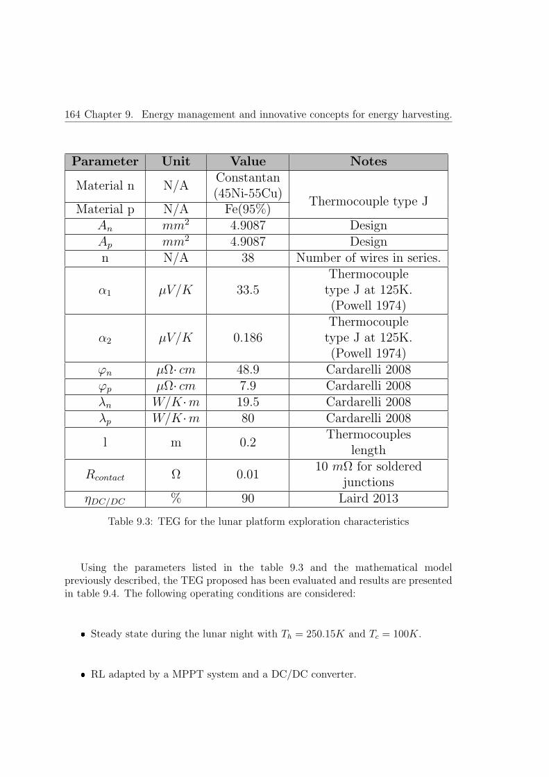
164 Chapter 9. Energy management and innovative concepts for energy harvesting.
Parameter Unit Value Notes
Material n N/AConstantan(45Ni-55Cu)
Material p N/A Fe(95%)Thermocouple type J
An mm2 4.9087 DesignAp mm2 4.9087 Designn N/A 38 Number of wires in series.
α1 μV/K 33.5Thermocoupletype J at 125K.(Powell 1974)
α2 μV/K 0.186Thermocoupletype J at 125K.(Powell 1974)
ϕn μΩ· cm 48.9 Cardarelli 2008ϕp μΩ· cm 7.9 Cardarelli 2008λn W/K·m 19.5 Cardarelli 2008λp W/K·m 80 Cardarelli 2008
l m 0.2Thermocouples
length
Rcontact Ω 0.0110 mΩ for soldered
junctionsηDC/DC % 90 Laird 2013
Table 9.3: TEG for the lunar platform exploration characteristics
Using the parameters listed in the table 9.3 and the mathematical modelpreviously described, the TEG proposed has been evaluated and results are presentedin table 9.4. The following operating conditions are considered:
� Steady state during the lunar night with Th = 250.15K and Tc = 100K.
� RL adapted by a MPPT system and a DC/DC converter.
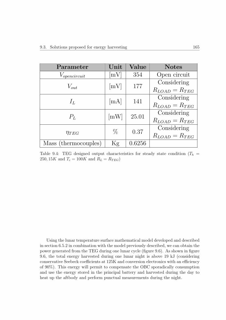
9.3. Solutions proposed for energy harvesting 165
Parameter Unit Value NotesVopencircuit [mV] 354 Open circuit
Vout [mV] 177Considering
RLOAD = RTEG
IL [mA] 141Considering
RLOAD = RTEG
PL [mW] 25.01Considering
RLOAD = RTEG
ηTEG % 0.37Considering
RLOAD = RTEG
Mass (thermocouples) Kg 0.6256
Table 9.4: TEG designed output characteristics for steady state condition (Th =250, 15K and Tc = 100K and RL = RTEG)
Using the lunar temperature surface mathematical model developed and describedin section 6.5.2 in combination with the model previously described, we can obtain thepower generated from the TEG during one lunar cycle (figure 9.6). As shown in figure9.6, the total energy harvested during one lunar night is above 19 kJ (consideringconservative Seebeck coefficients at 125K and conversion electronics with an efficiencyof 90%). This energy will permit to compensate the OBC sporadically consumptionand use the energy stored in the principal battery and harvested during the day toheat up the aftbody and perform punctual measurements during the night.

166 Chapter 9. Energy management and innovative concepts for energy harvesting.
Figure 9.6: TEG performance during one lunar cycle
9.3.3 Solar energy harvesting
Solar panels design
The proposed platform harvests the great part of the energy from the Sun usingsolar cells. Solar panels cover the outer surface of the platform. The tetrahedralplatform permits to locate solar cells in each of its three faces, thus harvesting energyfrom any of them independently of the platform orientation and the Sun position inthe lunar sky.
As depicted in figure 5.1 and figure 7.3 the aftbody integrates three different setsof solar panels:
1. Solar panels in the outer side of the solar petals. These panels are aimed toprovide the required energy to the platform to open the solar petals using therelease mechanism described in section 5.2.4. Once deployed, these panels willbe no longer used for energy harvesting as they will be facing the planet surface.
2. Solar panels located in the inner part of the solar petals. Once the solar petalsare deployed these panels will be directly facing the sky to harvest the solarenergy during the lunar day.

9.3. Solutions proposed for energy harvesting 167
3. Solar panels located in each face of the tetrahedral platform. These panels willbe exposed to the lunar environment when the solar petals were deployed.
The solar cell selection is of major importance to optimize the panel performance. Inthe last decades several new photovoltaic (PV) technologies have evolved to obtainnowadays efficiencies above the 30%. The solar energy is the main power source in thesatellite market, thus PV technologies for space are mature technologies with a largeheritage. The solar cells required for the platform herein proposed share the samerequirements that the satellite market in terms of radiation, operational temperaturerange, high efficiency and reliability. However, the platform proposed poses newrequirements to the solar panels as high shock, ultra-low temperature survival anddust contamination between others.
The solar panels construction conceived for the platform proposed is based in thefollowing design considerations.
� The solar panels are mounted directly on top of flexible PCBs whichincorporates the solar cells interconnections, circuitry and protection diodes.In this way the solar panels are attached to the aluminum metal frames ofthe platform structure. In the case of the solar petals, the PCBs that supportthe solar panels have solar cells installed in both PCB sides, enabling solarharvesting when the solar panels are non-deployed and deployed as previouslydescribed.
� The solar cells selected are flexible solar cells. High efficiency flexible solar panelsare currently in an advance TRL for space application, and in the following yearswill be commonly used in numerous missions ( [Beernink et al., 2007], [Law et al.,2006], [Trautz et al., 2013] and [King et al., 2006]). These high efficiency solarcells have the advantage of be low mass and more tolerant to vibration andshock than the traditional rigid approximation. A 28% efficiency is supposedfor this solar cells based on [Edmondson et al., 2006].
� The flex solar cells are mounted following a sandwich approach. Flex polyimidePCB works as subtract for the solar cells mounted on top. A polymer,transparent to the wavelengths of interest, is deposited on top of the solar cell.This polymer will integrate the dust removal technology as later explained. Thesolar panels are structurally supported by the aluminum structure of the petals.As explained in section 7.2.3 solid sublimating material permits the cohesion ofthe different elements protecting the solar cells during the landing impact.
� Dust removal technology is proposed in order to reduce the dust accumulatedover the solar panels, extending in this way the mission life. The dust removaltechnology proposed for this platform is based on the electric curtain concept

168 Chapter 9. Energy management and innovative concepts for energy harvesting.
developed by NASA in 1967 ( [Tatom et al., 1967]), and later developed,improved and refined during the following years by numerous researchers. Itsworking principle is based on a series of parallel electrodes connected to anAC source that generates a traveling wave acting as a contactless conveyor.Particles are repelled by the electrodes used to produce the field and travel alongor against the direction of the wave, depending on their polarity as explainedin [Calle et al., 2008]. This technique is particularly suitable for the platformproposed as it can be integrated easily in the sandwich structure previouslyintroduced. Additionally, during the lunar days there is power in excess toperform punctual cleaning procedures in order to maintain the solar cells cleanfrom dust.
Solar energy harvesting mathematical model
A mathematical model is required to predict the power generated by the solar cellsin function of the solar irradiance received in each solar panel of the platform. Thismodel will be used by the OBC during the planning to estimate the power generatedby the solar cells in the following hours or days. Therefore the model shall reduce asmuch as possible the OBC processing effort (power consumption reduction) withoutcompromise the results accuracy.
The solar cells produce electricity from Sun with a certain efficiency that is directlydependent on the technology and external factors as the temperature. The solar cellefficiency can be obtained with the following mathematical relation:
η =(V ·C)max
I·A (9.13)
Where (V ·C)max is the maximum power produced (as product of potential andcurrent) by the solar cell or panel at 25�C, I is the solar irradiance in W/m2
necessary to obtain the maximum power output of the cell and A is the solar cellarea illuminated.
From this efficiency parameter it is possible to estimate the power generated bythe different solar panels in function of the solar irradiance energy I with the followingrelation:
W = η·PF · I·A (9.14)
The parameter PF (with values between 0 and 1), is the packaging factor used toderive the effective cell area in the panel accounting the area loss between cells due towiring or empty spaces required for thermal contraction and expansions of the solarpanel.

9.3. Solutions proposed for energy harvesting 169
The solar cell area illuminated in each moment directly depends on the platformorientation with respect to the Sun and the solar incident angle. The solar incidentangle is obtained from the mathematical model developed in chapter 6.4.2 and theplatform orientation (ϑ) w.r.t the lunar equator is an input for the mathematicalmodel. With these two parameters it is possible to use geometrical relations todiscretize the solar area illuminated.
The model generated provides the power generated in each solar panel in functionof the date, solar irradiance, solar incident angle, selenographic latitude and longitudeand platform orientation (ϑ) w.r.t the lunar equator:
Psolar panel [W ] = f(t, I, a, λd, ϕd, ϑ) (9.15)
The construction parameters of the solar cell are shown in table 9.5.
Parameter Unit Value NotesPetal solar panel area m2 0.01151Faced solar panel area m2 0.009222
70% of area available effective for solar panels
η - 0.28 From Law 2006PF - 0.84 From Law 2006
Table 9.5: Solar panels parameters construction
Figure 9.7 presents the energy results obtained using the model developed for 1lunar day (January 2016), with the face 1 of the platform oriented with respect tothe lunar equator and been the platform located in the lunar equator (0�latitude,0�longitude).
As it can be appreciated in the figure, the power generated per each cell dependson the Sun angular incidence. In the example selected, the solar cells located in petal1 and face 1 are directly facing the Sunrise, thus generating power during the firstpart of the day. When the Sun is at the zenith all the solar cells generates power attheir respective maximum. As the Sun advances to the Sunset, the solar cells locatedin petal 1 and face 1 start progressively to enter in the dark area and are the rest ofthe solar cells which continue providing power to the platform node until the Sunset.
The total power generated in the equator has a maximum peak of 19.37 W (solarat zenith). In this calculations we have not consider the electronics efficiency thatwill reduce around a 10% to 15% the power generated. Additionally, as explainedin section 6.4.2 and shown in figures 6.10 and 6.11, the solar irradiance decreaseas function of the latitude. Using the model generated it is possible to plot themaximum power harvested during the zenith in function of the selenographic latitude(figure 9.8).
As it can be appreciated in figure 9.8, the maximum power harvested is drasticallyreduced as the incident angle reached by the Sun is reduced in function of the

170 Chapter 9. Energy management and innovative concepts for energy harvesting.
Figure 9.7: Solar power generated per solar panel (top), total power generated byall the solar panels (centre) and solar incident angle (bottom). Data obtained forJanuary 2016, 0�latitude,0�longitude and solar panel 1 facing the lunar equator.
latitude. In figure 9.8, the different slopes in the maximum power harvested, asthe latitude increases, are due to the geometrical disposition of the different solarpanels in funciton of the decreasing incident solar angle.
An immediate conclusion obtained from figure 9.8 is that the platform proposedcannot be used for poles exploration as the power obtained from the solar panelswould be near to cero during the winter .

9.3. Solutions proposed for energy harvesting 171
Figure 9.8: Maximum solar power harvested for January 2006 in function of theincreasing latitude towards North Pole (top); and maximum solar angle of the Sunin function of the latitude (bottom)


Chapter 10
High level control architecture
173

10.1. Control architecture introduction 175
10.1 Control architecture introduction
The exploration platform herein conceived is based on a complete autonomousbehavior. During a great part of surface operation time the platforms that conformsthe WSN will be unable to communicate with the orbiting satellite, the only linkbetween the nodes and the GS (Ground Segment). GS comprises all the Earth stationsand operation centers that are in charge of the network communications systems witha satellite or spacecraft.
The line-of-sight (LoS) duration of the link satellite with the platforms, in thecase of the Moon scenario, is around 18 minutes duration every 2 hours and 20minutes for an orbital inclination of 0�( as described in the Mission Design Reportof SWIPE, [Crosnier et al., 2013a]). Also, we have to consider that for the period ofthe lunar nights the reduced power availability could avoid platform communicationswith the orbiting satellite during a great part of the night duration. The reduced linktime shall be prioritized for data uploading reducing the downloading data as muchas possible.
One approximation, commonly followed in satellites control, is that the GSimplements all the planning and control activities. Therefore, the planning sequenceof commands is calculated in Earth and transmitted to the orbiting satellite that willexecute them as received. This low autonomy of the satellite is feasible while the timelack between the satellite and the GS is just of few seconds and the non-line-of-sightduration is highly reduced (several GS stations distributed around the globe couldreach a virtual 100% satellite coverage during the orbit).
This control paradigm changes drastically for planetary surface exploration. Aspreviously described. the reduced LoS duration and the high lack time between theGS and the SS (Space Segment) require another spacecraft control approximation.In this case the SS will take the responsibility of planning its own optimized taskssequence, execute them and even implement automatic recovery routines in case offailure conditions as described in figure 10.1.

176 Chapter 10. High level control architecture
Figure 10.1: Traditional remote control and proposed control scheme.

10.1. Control architecture introduction 177
Therefore, the high level control architecture herein proposed shall be able ofachieving a complete autonomous and reliable operation of each WSN node, with theobjective of reaching predefined or dynamic objectives and also reacting to failuresor unpredicted situations considering the changing environment.
Different high level control architectures in robotics have been proposed aroundthe last 40 years. The control architecture paradigm has been traditionallydiscomposed in how the sense, planning and actuation activities are performed.The traditional approach during the first years of robotic history is to use a�sense-plan-act�scheme, where initially the robot used a world model to planits activities before to implement them. Brooks ( [Brooks, 1991]) introducedother approach, following a �sense-act�architecture where the robot would havespecial-purpose task-achieving subroutines (often called behaviors) to solve specificproblems in a reactive fashion. From here numerous authors proposed a hybridapproach based on a �plan-sense-act�. As described in [Bonasso et al., 1997], thisapproach generates a control architecture with a lowest layer of reactivity, a topmostlayer of traditional AI (Artificial Intelligence) planning and a middle layer whichtransformed the state-space representation of plans into the continuous actions of therobot.
The �plan-sense-act�approach will be used for the definition of the high levelcontrol architecture proposed in this thesis.
Figure 10.2 sketches the conceived architecture approach where the planningand checker module would represent the planning top layer of the architecture, thesequencer and the world model estimator would constitute the middle layer and thecontrol layer would be the lowest reactivity layer.

178 Chapter 10. High level control architecture
Figure 10.2: High level control architecture proposal.
An important remark is that, as described in section 5.5, the platform designedhas two distributed OBCs. A main OBC located in the penetrator body, underthe planet surface, and an auxiliary OBC located in the tetrahedral platform atthe surface. Both OBC shall share the architecture above described, in the caseof malfunction of the main OBC, the auxiliary OBC shall be able to commandthe node appropriately. The architecture handles this redundant situation thanksto a subroutine implemented in the payload�s FPGA and in the OBC sequenceras described in the following subsections. In the following subsections each blockdepicted in figure 10.2 is described.
10.2 The sequencer
The sequencer is the core element of the proposed architecture and coordinates thecontrol activities of the platform. As part of the middle layer, the sequencer launchesas required the modelling, planning or acting procedures.

10.2. The sequencer 179

180 Chapter 10. High level control architecture
Figure 10.3 depicts the proposed sequencer flowchart. The sequencer is based ona fail-safe state machine. The system has to be able to recover from unexpectedmalfunctions or endless loops. The control system uses two different approaches torecover from unexpected situations:
� Hardware approach: as described in section 5.6, the OBC is reset by an externaldevice if the processor embedded in the FPGA does not generate a control signalevery 5 seconds. In this way, if the microprocessor collapses, the external deviceresets the FPGA, forcing to reboot the firmware of the OBC from an externalnon-programmable memory. The application memory is also reset.
� Software approach. If during the execution of the different procedures launchedby the sequencer the time response of those procedures exceeds a predeterminedsafe time, the sequencer will be re-started. If the sequencer fails to implementa procedure three times, then it will force a hardware reset.
The sequencer has been defined as a very simplistic state machine that request morecomplex procedures of the abstraction layer (planner and checker), launches modellingprocedures or commands the control layer to start specific control actions followingthe output obtained from the planner.
As shown in figure 10.3, the sequencer departs from a low power sleep subroutine.The great part of the time the platform will be in an ultra-low power consumptionmode. In this mode all the electronics subsystems of the platform would be switchoff except for:
� Power subsystems.
� Payload�s FPGA (in a low power consumption mode, refer to section 5.6).
� OBC (in a low power consumption mode, refer to section 5.6).
During the low power consumption mode the OBC activity is limited to verify ifthe absolute timer (integrated in the OBC) indicates that the period of sleep timehas concluded. The sleep time was stablished before to enter into the sleep routine.If the timer indicates that it is time to wake up, the first action of the OBC is tocheck its status. The following flags stablish the control status of the sequencer:
� Failure flag (1,0). If the sequencer was not able to finish a determinate procedurethis flag is set to one.
� Last step (0. . . n). The different procedures are identified with a numericalindex. This flag indicates the last procedure launched by the sequencer beforeto enter in the sleep routine.

10.2. The sequencer 181
� N (0. . . 3). This parameter indicates the number of tries to finish a determinateroutine.
� M(0. . . 3). This parameter indicates the number of tries to implement aplan that could not be finished because the energy available or the externaltemperature was not adequate.
� Main OBC failure (0,1). This flag is set to 1 if the redundant OBC is developingthe tasks of the main OBC as explained later.
If the sequencer is recovering from an interrupted procedure, it will check if thenumber of tries are above three, in this case a hard reset is forced. In case the numberof tries tries of recovering are below three attempts, the sequencer will command thelast step interrupted.
If the failure flag is set to 0, a nominal operation of the sequencer is executed.The sequencer shall check the schedule and determinate if there is need of planning(no new tasks scheduled). If there is not new tasks in the plan a new schedule shallbe obtained from the planner. The planning sequence is as follows:
1. The world model estimator is executed.
2. With the model obtained the planner is launched considering initial planningconditions (temporal time, objectives and parameters that determinate if theobjectives are met).
3. The output of the planner is verified using the checker module. If the plan isnot feasible, the initial conditions are modified following a defined procedure(relax the objectives or reducing the horizon time for example) and the planneris started again.
If there was established a previous plan, then the sequencer will check the planfeasibility. If the plan is not feasible due to energy or temperature reasons, thenthe sequencer will go to sleep (previously setting the sleep time and the flags). Thisprocedure is repeated three times, if the plan could not be executed due to energyor temperature the third time, then a new plan shall be obtained from the planninglayer.
If the plan is feasible, the sequencer commands the control layer to execute thefollowing tasks as per planning sequence.
In parallel, the sequencer of the redundant OBC is periodically polling the mainOBC as explained in section 5.5. Figure 10.4 describes the parallel subroutinesexecuted in the redundant and main OBC related to this polling procedure.

182 Chapter 10. High level control architecture
Figure 10.4: OBC status checking subroutines between the redundant OBC and mainOBC.
10.3 World model estimator
The world model estimator is a set of mathematical functions that are able todeterminate the future evolution of the platform environment. Provided a temporalhorizon (Δt), the mathematical models generated are able to estimate an outputvalue of the requested parameter with a time resolution of 1 hour.
The objective of the developed world model estimator is to provide a realisticestimation of the environmental boundary conditions. With this information thedeliberative layer would be able to obtain the most optimal plan for the autonomousplatform.
The different mathematical models developed have been described previouslyalong the different thesis chapters. All of them have been designed in order to simplifyas much as possible the processing effort (power consumption reduction) maintainingthe required resolution for their respective objectives. Following, a brief overview ofthe different models developed is presented:

10.3. World model estimator 183
Irradiance.The solar irradiance model is described in detail in section 6.4.2. This model providesthe total solar irradiance [W/m2] and the solar incidence angle [rad]:
Irradiance(t)
[W
m2
]= f(selen.latitude, selen.longitude, date,Δt) (10.1)
(10.2)
Incidence angle(t)[rad] = f(selen.latitude, selen.longitude, date,Δt) (10.3)
The model requires the selenographic coordinates of the platform and the currentdate to provide the solar irradiance evolution for the temporal horizon (Δt).
Moon surface temperature.The Moon surface temperature model is described in detail in section 6.5.2. The modelprovides the temperature in Kelvins of the Moon surface considering the incidentirradiance (obtained using the irradiance model), the date and the temporal horizon:
Moon surface temperature(t)[K] = f(Irradiance(t), date,Δt) (10.4)
Platform power consumption.The platform power consumption will depend on the tasks executed by the platform.In section 9.2 the equations that relate the power consumption for each operation areprovided (table 9.2). In this way, the power consumption of the platform [W], can beestimated in function of the tasks scheduling and the temporal horizon.
Power consumption(t)[W ] = f(tasks scheduling,Δt) (10.5)
Platform temperature.A thermal mathematical model has been developed and described in detail in section8.2. Thermal mathematical models are intrinsically complex and power demandingmodels. In order to reduce the complexity of the mathematical model withoutcompromising the resolution objectives the platform was sub-divided in differentisothermal nodes (refer to figure 8.1).
Isothermal node n temp.(t)[K] = f(Irradiance(t), solar incidence angle(t)
orientation(ϑ),Moon surface temperature(t), Power consumption(t), date,Δt)(10.6)
This mathematical model provides the temperature evolution of each isothermalnode in function of the irradiance, solar incidence angle,platform orientation andMoon surface temperature which most of them are obtained using the mathematical
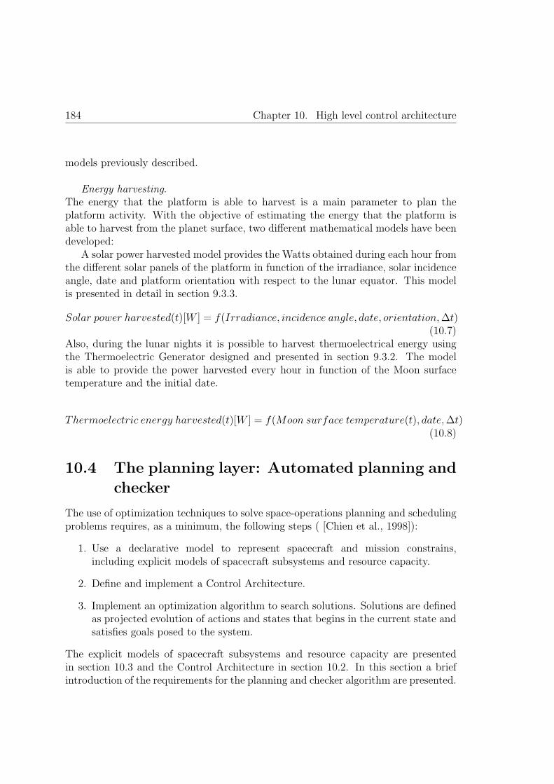
184 Chapter 10. High level control architecture
models previously described.
Energy harvesting.The energy that the platform is able to harvest is a main parameter to plan theplatform activity. With the objective of estimating the energy that the platform isable to harvest from the planet surface, two different mathematical models have beendeveloped:
A solar power harvested model provides the Watts obtained during each hour fromthe different solar panels of the platform in function of the irradiance, solar incidenceangle, date and platform orientation with respect to the lunar equator. This modelis presented in detail in section 9.3.3.
Solar power harvested(t)[W ] = f(Irradiance, incidence angle, date, orientation,Δt)(10.7)
Also, during the lunar nights it is possible to harvest thermoelectrical energy usingthe Thermoelectric Generator designed and presented in section 9.3.2. The modelis able to provide the power harvested every hour in function of the Moon surfacetemperature and the initial date.
Thermoelectric energy harvested(t)[W ] = f(Moon surface temperature(t), date,Δt)(10.8)
10.4 The planning layer: Automated planning and
checker
The use of optimization techniques to solve space-operations planning and schedulingproblems requires, as a minimum, the following steps ( [Chien et al., 1998]):
1. Use a declarative model to represent spacecraft and mission constrains,including explicit models of spacecraft subsystems and resource capacity.
2. Define and implement a Control Architecture.
3. Implement an optimization algorithm to search solutions. Solutions are definedas projected evolution of actions and states that begins in the current state andsatisfies goals posed to the system.
The explicit models of spacecraft subsystems and resource capacity are presentedin section 10.3 and the Control Architecture in section 10.2. In this section a briefintroduction of the requirements for the planning and checker algorithm are presented.

10.4. The planning layer: Automated planning and checker 185
The proposed architecture does not impose a specific declarative model or planningalgorithm. The final selection of the planning algorithm shall be done in function ofthe specific mission constrains and development group expertise. Although somerestrictions shall be considered:
� Power consumption. The selected algorithm shall reduce the power consumptionof the OBC to a minimum. Unlike mobile robots, the proposed platform doesnot require fast responsivity to external events. The time availability to planthe activities and perform them is in the range of several minutes or even hours.
� The system shall plan, schedule and execute hard constraints, which thesystem must satisfy, and soft constraints or preferences, which the system mustoptimize:
– Satisfy:
� Ensure integrity and operability of the platform.
� Manage the energy available in order to plan the switch-on, switch-offand hibernation of the platform and their related subsystems, ensuringa continuous operation of the main OBC.
� Maintain housekeeping data updated in order to adequate the planningto the current status of the platform.
– Optimize
� Maximize the payload science return in function of constrains andresources availability.
� Maximize the data communication within the WSN and the satellitelink in function of constrains and resources.
� Data analysis and prioritization: Analyze the extracted features toassess the scientific value of the data and to generate new science goals.Opportunistic goals may be added to the plan as long as resources andother operational constraints are still met and all higher priority goalscan be achieved ( [Castano et al., 2007]). Depending on the mission,different opportunistic goals for the platform proposed in this thesiscan be defined, as for example detail monitoring of an eclipse.
� The planning algorithm shall be able to accept new goals. The GS can generatenew goals in function of conclusions extracted from the previous data analyzedin ground or in order to solve a deviation or malfunction of the planner. Thenew goals shall be defined following the declarative model used by the planningalgorithm and transmitted to the platform thru the orbiting satellite.

186 Chapter 10. High level control architecture
Collaborative algorithm. The predefined or dynamic goals could includecooperative goals between the nodes of the WSN. The planning algorithm shallpermit certain collaborative functions in order to achieve a common goal in theWSN. For example, synchronize the measurement of a certain environmentalphenomenon by all the nodes of the platform.
The algorithm shall contemplate closed planning horizons. Batchapproximation shall be considered. Time is divided up into a number of planninghorizons, each of which lasts for a significant period of time. When near theend of the current horizon, it is projected what the state will be at the end ofthe execution of the current plan ( [Chien et al., 2000]).
Figure 10.5 presents an overall overview of the planning algorithm:
Figure 10.5: Planning algorithm scheme overview.
Finally a checker shall be defined. The combinatory of all the possible statesand events do not allow the programmers to have an exhaustive representation ofthose states and transitions in order to prove a priori the correctness of the behaviour( [Blanquart et al., 2004]). Two initial approaches can be followed:

10.5. The control layer 187
1. Extensive simulation testing to increase the statistical confidence of theautonomous system correct behaviour.
2. Safety dynamic supervisor to ensure that catastrophic failures are avoided.
The second option is herein selected (without detriment of a preliminary exhaustivesimulation testing in the laboratory prior to the mission launch). Plan verificationconsists of checking, that a generated plan satisfies certain properties. [Bensalem et al.,2014] presents and exhaustive literature review of different validation and verificationapproaches.
10.5 The control layer
The control layer is aimed to interface directly with the hardware. The control layer,commanded by the sequencer, performs the exact sequence of hardware operationsaimed to perform a specific action or monitor sensor values. A list of the differenthardware operations of the control layer is presented in the following table.

188 Chapter 10. High level control architecture
Hardwareoperation
Hardware subsystems involved
Surface Temperaturemeasurement
-Acquisition electronics: Analog to digital chain commanding (including ADC interface)-Power module: switch on and off the related sensor/electronics.
-Memory access.
Surface Temperaturemeasurement
-Acquisition electronics: Analog to digital chain commanding (including ADC interface)-Power module: switch on and off the related sensor/electronics.
-Memory access.
Irradiance measurement-Acquisition electronics: Analog to digital chain commanding (including ADC interface)
-Power module: switch on and off the related sensor/electronics.-Memory access.
TID measurement-Acquisition electronics: Analog to digital chain commanding (including ADC interface)
-Power module: switch on and off the related sensor/electronics.-Memory access.
SEU measurement-Acquisition electronics: Analog to digital chain commanding (including ADC interface)
-Power module: switch on and off the related sensor/electronics.-Memory access.
Tetrahedral platformactive heating
-Power module: PowerON/OFF of the corresponding heater
DDS calibration-Acquisition electronics: Analog to digital chain commanding (including ADC interface)
-Power module: switch on and off the related sensor/electronics.-Memory access.
DDS measurement-Acquisition electronics: Analog to digital chain commanding (including ADC interface)
-Power module: switch on and off the related sensor/electronics.-Memory access.
Hibernation/Sleep-Power module: switch off/on the different electronics modules
to enter in a low power consumption state.-Memory access.
Housekeeping measurement-Acquisition electronics: Analog to digital chain commanding (including ADC interface)
-Power module: switch on and off the related sensor/electronics.-Memory access.
Radio interfacecommunication
-Power module: switch on and off the radio interface module-Radio interface module: Command the communications module to send/receive data.
-Memory access.
Solar panels deployment-Power module: switch on
and off the Pin Puller in function of the output received from the end ofstroke sensor.
Table 10.1: Control layer hardware operations.

Chapter 11
Platform prototyping andlaboratory test results
189


11.1. Platform prototyping introduction 191
11.1 Platform prototyping introduction
Under the scope of SWIPE project it was possible to manufacture and test functionalprototypes of some elements of the platform proposed in this thesis. This chapterdescribes the hardware elements manufactured, the tests performed and the resultsobtained.
Specifically the following elements were manufactured and tested:
� Tetrahedral surface platform. The distribution of subsystems within theplatform is different to the distribution proposed in this thesis, however thetetrahedral platform size and functionality is the same.
� Payload.
– Dust Deposition Sensor.
– Irradiance Sensor.
– Radiation sensor.
– Surface temperature sensor.
� Thermal switch.
� Release mechanism.
In the other hand, the following technologies and concepts proposed in this thesisare not covered, included or considered within the SWIPE project:
� Platform deployment system over the planet surface: the penetrator conceptand auxiliary shock absorption subsystems.
� Thermal design.
� Thermoelectric and thermal energy harvesting techniques.
� Redundant techniques herein proposed.
� OBC high level architecture and related mathematical modelling.
The design approach followed for the functional prototypes under the scope of SWIPEproject was to provide a space compatible hardware; any material, EEE component,mechanical part or process has an equivalent space qualified part/material/process. Itis understood as equivalent any space qualified material, EEE component, mechanicalpart or process that could substitute the commercial/industrial grade used in theprototype with minimum impact or changes to the design of the system. Following

192 Chapter 11. Platform prototyping and laboratory test results
this philosophy it was possible to reduce the costs of the prototype while still havingits results comparable with those potentially obtained by space qualified hardware.
Figure 11.1 presents the tetrahedral platform prototype developed under theSWIPE project and its different elements:
11.2 Tetrahedral platform structure
The tetrahedral platform structure concept proposed in this thesis for the surfacetetrahedral platform was manufactured and results obtained are shown in figure 11.2.
Figure 11.2: Node structure assembled (left). Upper structure with PP assembled(center). Lower structure with electronics rack integrated (right).
The tetrahedral platform is highly reduced in volume. This fact directlyimplies that the volume available inside the node is highly reduced and optimized,consequently challenging the integration procedure. The integration procedure of thenode was considered from the design phase. The mechanical structure was designedto be subdivided in two sub-assemblies: upper structure and lower structure (refer tofigure 11.2). This subdivision was envisaged with the objective of ease the integrationprocedure: firstly the different subsystems are integrated in each sub-assembly andthe complete node structure is finally integrated by assembling both upper and lowerpart. In the base of the lower structure is located the thermal switch (number 4 inthe figure) and the electronics rack is attached on top of the thermal switch. Anauxiliary low thermally conductive piece (number 8 in the figure) is used to providestiffness to the electronics bay, attached to the lower part of the structure, without

11.2. Tetrahedral platform structure 193
Figure 11.1: SWIPE node platform without solar panels (top); SWIPE node withsolar panels closed and power cable (bottom left) and open with power cable removed(bottom right).

194 Chapter 11. Platform prototyping and laboratory test results
compromise the thermal isolation. To avoid different potential levels in the metalchassis of the structure and the electronics rack, electrical bonding consisting on thinmetal pieces (number 10 in the figure) are used. This is of main importance to ensurea low impedance interconnection of all the metal elements of the structure.
The total mass of the node structure and petals structure is 520 grams.
11.3 Solar panels deployment system, functional
tests and results
The release mechanism of the solar panels (detail described in section 5.2.4 and figure5.3), was manufactured and integrated in the SWIPE platform.
Several functional test of the release mechanism was carried out as describedbelow:
1. The release mechanism was integrated in the platform structure.
2. The petals were closed and screwed to the three arms interface metal piecesusing the holding elements attached to the petals.
3. In order to simulate the terrain conditions fine sand was used as substrate forthe deployment tests.
4. 10 successive deployments were performed and recorded. Figure 11.3 shows thedeployment sequence.
Figure 11.3: Solar panels deployment sequence.
In all the cases the results were completely successful:
The deployment of the petals was complete.

11.4. Scientific payload prototype functional tests and results 195
After a detail visual and functional inspection, any damage or malfunction wasidentified in the solar cells.
Low temperature tests were performed with the objective to verify the properdeployment performance at low temperatures
Figure 11.4: Low temperature tests.
Two different tests were performed:
Independent actuation of two Pin Puller devices at -12 C (figure 11.4, right).The actuators performed properly at the nominal power consumption range.Actuation time was below 7 seconds in both cases.
Platform deployment at -14 C (figure 11.4, left). The platform deployed thesolar panels successfully in 7 seconds.
11.4 Scientific payload prototype functional tests
and results
11.4.1 Dust Deposition Sensor prototype and laboratorytests results
The Dust Deposition Sensor (DDS) is a sensor-actuator system aimed to characterizethe rate of dust deposited over its surface, as detailed described in section 6.2. SeveralDDS (including the acquisition electronics and a micro-actuator) were manufacturedand integrated under the scope of the SWIPE project (figure 15). Functional,electrical and mechanical tests were performed.

196 Chapter 11. Platform prototyping and laboratory test results
Figure 11.5 shows an activation sequence of the actuator integrated in the DDS forthe in-flight calibration of the sensor. As it can be seen, at ambient temperature, themicro-actuator is able to place a reflector on top of the optical window in 12 seconds.An additional test was performed at -15 C were the calibration actuator performedcorrectly with a nominal power consumption of 2A and with a total actuation timeof 19 seconds. Table 11.1 presents the power details during both tests.
Figure 11.5: DDS actuator activation sequence at ambient temperature.
Potential[V]
Temperature[ ]
Current consumption[mA]
Actuation time[seconds]
+5V +25 2000 12+5V -10 2000 19
Table 11.1: Power consumption DDS actuator test results.
Two tests campaigns were performed to demonstrate the performance of thedesigned sensor. During the first DDS test campaign a lunar dust simulant wasused with the aim to demonstrate the performance of the sensor under dust samplessimilar to those expected to be found on the Moon surface. The objective of thesecond test campaign was to characterize the DDS response to samples of dust moresimilar to those that could be expected during the field test, which will be performedunder Earth conditions.
Limited availability, high cost and toxicity of Lunar regolith simulants madeimpossible to test the DDS using such simulants. Instead an available commercialnon-toxic lunar simulant was selected, which fulfilled the objective to test/calibratethe DDS with the best possible fidelity. A 5μm white corundum (Al2O3) waschosen due to its refractive index at near IR, irregular shape, commercial availability,non-toxic characteristics and sample preparation characteristics as explained below.

11.4. Scientific payload prototype functional tests and results 197
A 100μ m grey corundum was used during the second test campaign. Grey corunduminstead white corundum was selected to be consistent with Earth s conditions. In aMoon scenario, the dust will be deposited over the optical window by electromagneticlevitation with a size not larger than 5μm ( [Stubbs et al., 2006]). Meanwhile in anEarth scenario, the dust can be deposited over the optical window mainly by thewind. As the DDS is situated just only 150mm above the soil and the terrain ofthe Earth analogue scenario lacks any vegetation cover, the dust particles that couldreach the optical window are expected to be much larger than in the case of the Moonscenario.
During the samples preparation it was required to uniformly distribute a knownquantity of dust particles over the optical window surface as expected to occur duringa natural deposition. Any mechanical means to dispose a low quantity of dust wasdiscarded. It was required to use distilled water to put the dust particles in suspension.In this way it would be possible to weight a small quantity of dust and mix-up withwater in order to dispose a drop of water (130μl) on to the optical window with anestimated concentration of dust.
Figure 11.6: 5μm samples with a different dust particles distribution over theoptical window (top); 100μm Corundum sample (bottom right); and 100μm glassmicrospheres sample (bottom left).
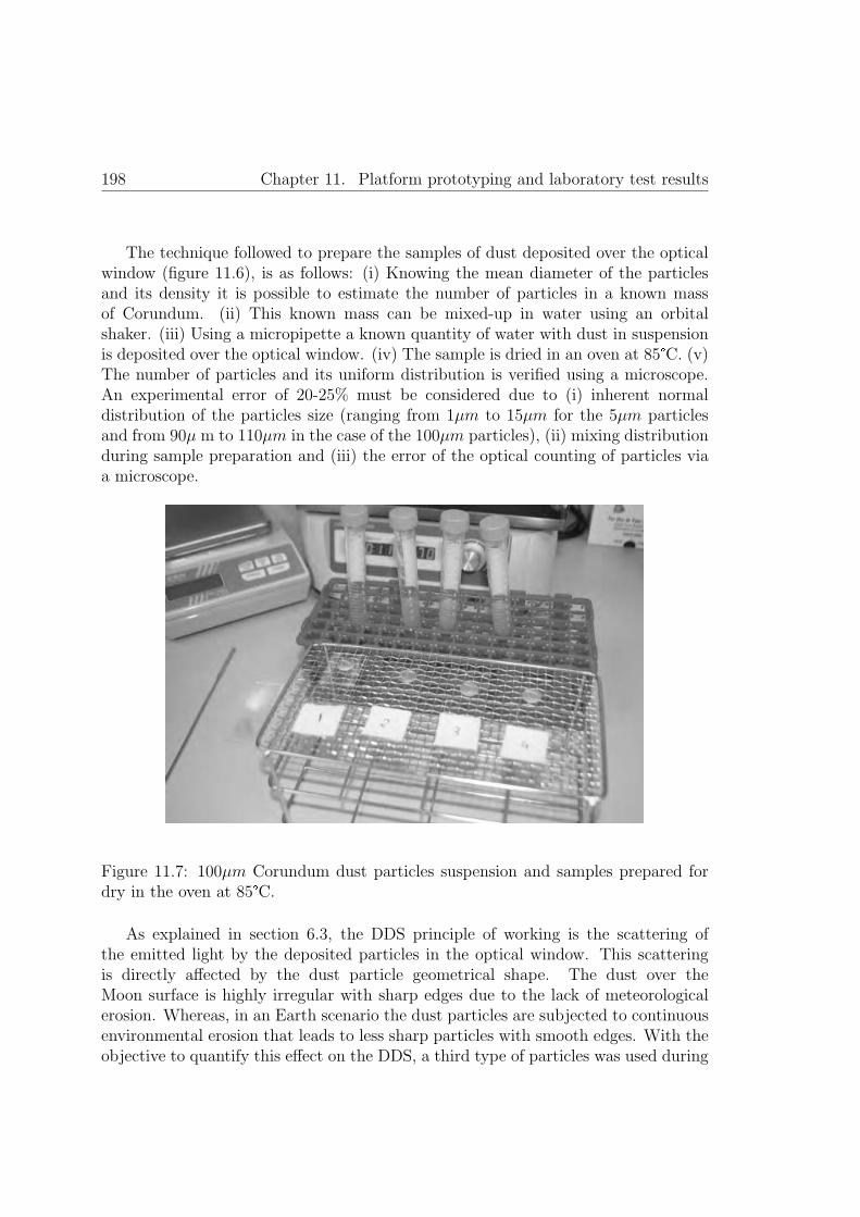
198 Chapter 11. Platform prototyping and laboratory test results
The technique followed to prepare the samples of dust deposited over the opticalwindow (figure 11.6), is as follows: (i) Knowing the mean diameter of the particlesand its density it is possible to estimate the number of particles in a known massof Corundum. (ii) This known mass can be mixed-up in water using an orbitalshaker. (iii) Using a micropipette a known quantity of water with dust in suspensionis deposited over the optical window. (iv) The sample is dried in an oven at 85�C. (v)The number of particles and its uniform distribution is verified using a microscope.An experimental error of 20-25% must be considered due to (i) inherent normaldistribution of the particles size (ranging from 1μm to 15μm for the 5μm particlesand from 90μ m to 110μm in the case of the 100μm particles), (ii) mixing distributionduring sample preparation and (iii) the error of the optical counting of particles viaa microscope.
Figure 11.7: 100μm Corundum dust particles suspension and samples prepared fordry in the oven at 85�C.
As explained in section 6.3, the DDS principle of working is the scattering ofthe emitted light by the deposited particles in the optical window. This scatteringis directly affected by the dust particle geometrical shape. The dust over theMoon surface is highly irregular with sharp edges due to the lack of meteorologicalerosion. Whereas, in an Earth scenario the dust particles are subjected to continuousenvironmental erosion that leads to less sharp particles with smooth edges. With theobjective to quantify this effect on the DDS, a third type of particles was used during

11.4. Scientific payload prototype functional tests and results 199
5μm Corundum 100μm Corundum 100μm SiO2 microspheresResolution[
particlescm2
] 750 12 150
Accuracy[particles
cm2
] 3800 21 350
Dynamic range[particles
cm2
] 3.8· 103-1· 107 21-2.5· 104 350-3· 104
Table 11.2: Summary of results obtained during the two DDS laboratory testcampaigns.
the second test campaign. Silica glass (70% SiO2, 15% Na2O) microspheres with anaverage diameter of 100μm were employed, as shown in teh top picture of figure 11.6.The transmittance of these particles is expected not to be lower than 75% at nearIR. With these characteristics the voltage output of the DDS is expected to be muchlower than a similar number of corundum particles of the same size. Several sampleswith different concentration were prepared, optically verified via a microscope andmeasured with the DDS. The results are summarized in table 11.2.
As expected, the sensor accuracy with corundum particles of 5μm is around twoorders of magnitude lower than with corundum particles of 100μm. This is consistentwith the working principle of the DDS, where bigger sharp particles would scattermore efficiently the light pulses compared to smaller particles. It has to also be takeninto account that the grey corundum particles have a lower near IR transmittanceindex than the white corundum particles, thus reflecting more efficiently the IR lightpulses. It is important to mention that as low as 21 particles/cm2 of 100μm and3800 particles/cm2 of 5μm were measured with the DDS, thus demonstrating thegood performance of the sensor.
Figure 11.6 shows a uniform distribution of particles in the corundum samples,however the Silica glass samples could not be distributed uniformly on the opticalwindow. Silica glass particles tended to group during the evaporation process asshown in figure 11.6. This has to be considered because it affects directly thescattering pattern, reducing the scattering effect of the whole sample compared touniformly distributed particles. Although a precise relationship associated with thiseffect could not be established, it could clearly be observed that the spherical glassparticles affect the performance of the DDS reducing its accuracy by approximatelyone order of magnitude.
We can conclude from the obtained results that the DDS is a low powerconsumption and low mass sensor able to detect low quantities of dust with a fourorders of magnitude dynamic range. This sensor is optimized for the small sharpparticles expected to be found over the Moon surface.
Several samples with different particle concentration were prepared and measured

200 Chapter 11. Platform prototyping and laboratory test results
using the DDS and acquisition electronics. An OBC simulator installed in a PCwas used to store the data obtained. It is important to remark that the measureswere obtained in dark conditions (closed cabinet) to avoid ambient light disturbances.Minimum square regression was used to obtain a calibration equation using the dataobtained from the 100μm corundum samples:
Dust Deposited
[particles
cm2
]=
(7288.8· ( x·5
4095− 0.117
)1.8459)1.32732
(11.1)
*Where X is the 12 bits value read from the ADC coded in decimal.
In future developments, this sensor could be improved including different emittersat different wavelengths. This could allow obtaining information about the dustdeposition size distribution that would be a valuable scientific return. However, sucha modification would imply an overhead in power, mass and complexity of the retrievalalgorithm.
11.4.2 Irradiance sensor prototype and laboratory testresults
Multiple irradiance sensors were manufactured under the scope of SWIPE projectand integrated in the tetrahedral platform as shown in figure 11.8.
Figure 11.8: Assembledirradiance sensor.
The irradiance sensor has been calibrated experimentally using commercialcalibrated photodiodes of similar spectral response than the photodiodes selected forthe irradiance sensor. In an optical test bench, different reference emitters were usedto provide the same reference to the calibrated photodiodes and to the photodiodesunder calibration. Both output curves of the reference photodiodes were used to

11.4. Scientific payload prototype functional tests and results 201
calibrate the SWIPE photodiodes. A pointer laser and millimetre positioners wereused to position both sensors at the same location from the reference emitters. Themeasurements were performed in darkness to avoid ambient light disturbances.
Figure 11.9: Optical test bench (left and center) and measurements at ambient light(right).
The gain of the proximity electronics included in the acquisition electronics PCBwas initially designed for the expected irradiance over the Moon surface. The gainof the irradiance photodiodes was modified considering the expected irradiance inthe field test in order to optimize the dynamic range of the sensor. The expectedirradiance in the field test was obtained from [Maturilli et al., 2014].
Using the data obtained the following calibration equations were obtained for eachspectral band of the irradiance sensor (in the following equations X is the 12 bits valueread from the ADC coded in decimal):
UV:
PUV
[mW
cm2
]=
(14.511·
(x· 54095
))+ 0.1293 (11.2)
IR:
PIR
[μW
cm2
]=
(1.8096·
(x· 5· 10004095
))− 0.6783 (11.3)
VIS:
PV IS
[μW
cm2
]=
(2.741·
(x· 5· 10004095
))+ 58.871 (11.4)

202 Chapter 11. Platform prototyping and laboratory test results
11.4.3 Surface temperature sensor prototype and laboratorytest results
Three thermal sensors responsible of measuring the upper surface temperature of theMoon are detailed described in section 6.5.3. Several sensors as those proposed inthis thesis were manufactured under the SWIPE project. The sensors measure thetemperature by conducting means. The temperature sensor is attached to a highthermal conductivity and low thermal inertia material (aluminium) that is used as aprobe for measuring the temperature (refer to figure 11.10). It is important to remarkthat the position of these sensors under the scope of SWIPE project is different tothe proposed in this thesis:
SWIPE project contemplates to locate the sensors at the end of the deployablewalls. In this way it is possible to use the force of the deploying panels tointroduce the solar probes into the lunar soil.
This thesis locates the soil temperature probes at the base of the platform (referto figure 5.1). As the platforms are deployed using a penetrator approach, thesoil probes will be introduced in the lunar soil during the platform landing.
Figure 11.10: Temperatureprobe prototype details

11.4. Scientific payload prototype functional tests and results 203
The temperature sensor was experimentally calibrated using boiling distilled waterand melting ice (using altitude corrections). This two absolute temperature referenceswere used to obtain two points of calibration.
Figure 11.11: Calibration of temperature sensor. 0 C top and 100 C bottom.
As shown in figure 11.11 a petal of the structure with a temperature probe installedwas used for the calibration campaign. The SWIPE acquisition electronics with anOBC simulator, installed in a PC using LabView, was used to obtain the output

204 Chapter 11. Platform prototyping and laboratory test results
value in each case. The probe was immersed in water with melting ice as shown infigure 11.11 (top) and in boiling distiller water as shown in figure 11.11 (bottom).For temperatures above 0 �C (the code in decimal for 0 �C is 2244). This equationhas been corrected using experimental data (in the following equations X is the 12bits value read from the ADC coded in decimal):
T [C] =
(255.52·
(x· 54095
))− 700.05 (11.5)
For temperatures below 0�C :
T [C] =
(250.51·
(x· 54095
))− 686.17 (11.6)
11.4.4 Acquisition electronics prototype
The acquisition PCB was manufactured, electronics components assembled andelectrical verification tests performed.
External power supplies were used to provide power to the acquisition PCB andto verify the proper operational behavior of all the blocks within the PCB. In thisprocess, it was found that the Op-amp AD8629 footprint did not properly fit thedevice package, so an external re-cabling was required. Once this modificationwas carried-out, the acquisition electronics worked as expected and the FPGAwas programmed using the firmware developed by the microelectronics group ofArquimea Ingenierıa. After firmware performance verification the irradiance sensors,the temperature sensor and the Dust Deposition Sensor were connected to theacquisition electronics PCB. With the objective to simulate the OBC commanding, an�OBC simulator�was programmed using Labview by the software group of ArquimeaIngenierıa. Following this approach, it was possible to debug completely the behaviorof the FPGA, correcting the FPGA�s firmware until the expected behavior of theacquisition PCB was obtained.
11.5 Thermal switch prototype functional tests
and results
The thermal switch was manufactured under the scope of the SWIPE project andtested taking the opportunity of a thermal vacuum test campaign of ArquimeaIngenierıa S.L.U. As it can be appreciated in figure 11.13, the thermal switch wasattached to the base plate of the thermal vacuum chamber. To ensure proper thermalconductivity low outgassing thermal filler was placed between the bottom plate of thethermal switch and the base plate of the thermal chamber.

11.5. Thermal switch prototype functional tests and results 205
Figure 11.12: Acquisition electronics PCB (left) and acquisition electronics integratedin the SWIPE structure (right).
Figure 11.13: Thermal switch test set-up.
A heater (power resistor) was used to heat up the upper plate of the switch.A temperature sensor (thermocouple) was attached to the top plate (spaced to theheater). The base plate of the thermal chamber was monitored in temperature andit is considered, for this test purposes, as an infinite thermal mass that does not

206 Chapter 11. Platform prototyping and laboratory test results
increase its temperature with the power generated by the heater and transmittedthru the thermal switch to its base.
With this simple set-up, it was possible to simulate the boundary conditions ofthe thermal switch and analyze its behavior.
With the base plate of the vacuum chamber stabilized at around -20 C (dwelltime three hours), the heater was turned on, dissipating 10W constantly. Figure11.14 presents the temperature of the top plate in function of the time. In red it isrepresented the data values with the thermal switch closed, and in blue the data valueswhen the thermal switch was open. Least square regression was used in both data setsof values (black line). As it can be seen, the temperature increased constantly from-20 to around 14 C when the slope drastically changed. This slope change (around30%) was due to the thermal switch actuation: when the thermal witch actuatedthe heat dissipated to the vacuum chamber increased, thus reducing the increasingtemperature slope.
Figure 11.14: Thermal vacuum test results.
The experiment verified the proper functional behavior of the thermal switch:clearly it closed when the temperature of the top plate was above the temperaturetransition of the SMA material. Although, it is important to consider the following:

11.5. Thermal switch prototype functional tests and results 207
1. The test was aimed to verify the functional behavior of the thermal switch,not to characterize its thermal conductance. More complex experiments arerequired for further characterization of the thermal switch.
2. Even though the experiment was not aimed to characterize the thermalconductance of the thermal switch, it could be quantitatively verified that:
(a) The thermal isolation was really good.
(b) The thermal conductance was not as good as expected. The thermalcontact of the thermal switch has to be improved; simple changes as changethe materials used in the thermal switch contact surfaces and increasingthe force of the SMA (a configuration using longer SMA or several fibresin series) would increase drastically the thermal conductance.


Chapter 12
Conclusions and future research
209

12.1. Conclusions 211
12.1 Conclusions
This thesis stablishes the technological basis for the implementation of a fixedscientific monitoring infrastructure over a planet surface. The concept proposedis aimed to provide a reliable and cost effective system for the continuous surfacemonitoring of the inner rocky planets of our Solar System.
Beyond the traditional rovers or landers, the concept proposed is composed bytents of self-powered and low mass autonomous platforms with the capability ofperform a variety of different scientific measurements. Those small fixed platformsare capable to sense, process, share between them and finally transmit data to aorbiter for further transmission to Earth using an ad-hoc Wireless Sensor Network.The conceived system is able to operate autonomously during years, harvesting therequired energy from the planet surface environment. Such a concept deployed overa planet surface would represent the first fixed infrastructure over an extraterrestrialrocky body.
The dissertation comprises the conceived mission approach for the Moon scenario,platform overall design and provides reliable technical solutions for the differentcritical aspects of the concept proposed. Even though, it was not possible to dealin depth detail with all the technologies involved in this thesis, a compressive studyis presented focusing in those aspects not completely covered in other previouslyproposed missions or concepts.
The platform conceived is a low mass dual body presented in chapter 5. Theplatform can be subdivided in two different bodies: (i) a tetrahedron body highlyoptimized both in mass (2000g) and volume (tetrahedron envelope of 200x200 mm ofbase and 200 mm of height) that will remain over the planet surface; (ii) a penetratorbody (3260 g) of 300 mm in height, 100 mm in diameter and with the shape of aballistic missile aimed to go between 0.3 and 1.2 meters below the subsurface of theplanet. The deployment method selected is penetration (hard-landing), simplifyingdrastically the descent system required, thus reducing the related costs (chapter 7).
The set of solutions proposed and the exploited synergies between the differentsubsystems makes the platform conceived to go beyond the state of the art (chapter4 ) with respect to similar platforms:
1. The system concept proposed enhances the science return increasingsignificantly the mission lifetime thanks to a reliable system able to operateduring years harvesting energy over the planet surface (chapter 9).
2. Day and night energy harvesting systems in combination with a smart thermalregulation (chapter 8) enhance the power efficiency of the platform and enablesthe node to be operative during the cold nights. A robust, extremely cheap and

212 Chapter 12. Conclusions and future research
flexible TEG that can extract small amounts of energy continuously during thelunar night has been proposed.
3. The cost of the platform is highly optimized thanks to its low mass and becauseRadioisotope Thermoelectric Generators are not used.
4. The platform includes reliable solutions to support the high shock levelsassociated with a hard landing (section 7.2.3). In this way the mass ofthe vehicles and fuel required to deploy the platform is significantly reduced,enabling the deployment of a larger number of platforms in each mission.
5. A highly integrated, low power and reduced mass payload (chapter 6) has beendesigned and developed. Each platform of the WSN can be configured withdifferent sets of instruments, thus increasing significantly the scientific objectivesof the whole mission. Novel dust deposition and radiation sensors have beendesigned. The test campaign demonstrated an excellent performance of theDust Deposition Sensor for planetary exploration.
6. The autonomous behavior of the platform is obtained thanks to a controlarchitecture that permits the platform plan and schedule the tasks in order toincrease the science return adapting itself to the changing environment (chapter10).
7. High reliability based on exploiting the synergies and redundancy possibilitiesbetween the subsystems of each platform and between the different platformsof the WSN.
8. The platform can be adapted to different mission scenarios, without significantlyredesigning their functionality. This permits to potentially use the presentedplatform concept for different mission objectives as other moons, asteroids orplanets.
Missions compatible with the concept proposed could take opportunity of thepreviously commented advantages from the platform conceived in this thesis. Certainmissions would not be compatible with the exploration concept proposed. Betweenothers, we can define two main points to be evaluated when deciding if a certain typeof mission is compatible with the platform conceived in this thesis:
� The conceived platforms, as presented in this thesis, are not compatible withPolar Regions or craters exploration. Significant modifications have to beconsidered to adapt the platforms proposed for the exploration of those dark andcold regions. Basically the modifications required suppose a significant increasein the mass and volume of the platforms and also in a lifetime reduction.
12.2. Future research 213
� Even though different set of sensors can be installed in each platform of theWSN, increasing the number of parameters monitored over the planet surface,it must be noted the complexity limitation (mainly in mass and volume) ofthe scientific payload that can be installed in these platforms. Highly complexinstruments with demanding mass, volume and energy requirements are notcompatible with the platform proposed.
Some of the solutions herein proposed have been developed under the scope of a FP-7project. The results obtained after the laboratory tests of the functional prototypesof the subsystems developed demonstrate the significant potential of the solutionproposed, as the Dust Deposition Sensor, tetrahedral configuration or low shock solarpanels deployment mechanism.
12.2 Future research
The proposed concept represents a reliable alternative for space exploration. However,from the concept presented in this dissertation to the final Flight Model there is along way to travel.
From the concept herein proposed and with the adequate support, it would bepossible to consider a phase A of an exploration mission, involving expert researchgroups and companies in the different fields required to consolidate the missionconcept and the platform design.
Additionally it is important to note that the dissertation presented in thisdocument is highly ambitious and cover a large different number of design areasand technologies. As it was not possible under the scope of this thesis develop indetail some of the solutions proposed, there are several areas susceptible of furtherresearch:
� The TEG concept proposed is susceptible to new improvements, particularlyin relation to the metal material selection, TEG construction and electronicsrelated.
� The sublimating material proposed in this thesis requires an extensive researchand testing.
� A specific planning algorithm and checker algorithm have not been developedunder the scope of this thesis. The custom development of the planning andchecker algorithms will be required for future developments of the platform.
� The mathematical models do not contemplate the topography of the Moon. Newimprovement at this respect will permit to adapt the design of the platform tonew scenarios.

214 Chapter 12. Conclusions and future research
� Further work is required to improve the performance of the thermal switch thatdemonstrated a great potential and proper functional behavior in vacuum butwith a reduced thermal conductivity when closed.

Bibliography
[Albee et al., 2000] Albee, A., Battel, S., Brace, R., Burdick, G., Casani, J., Lavell,J., Leising, C., MacPherson, D., Burr, P., and Dipprey, D. (2000). Report onthe loss of the mars polar lander and deep space 2 missions. NASA STI/ReconTechnical Report N, page 61967.
[Alvarez et al., 2011] Alvarez, F., Collado, M., Nava, N., and Cabas, R. (2011).Qualification results of the qualification model of a rotary actuator based onshape memory alloy for operation in mars. In 14th European Space Mechanisms &Tribology Symposium (ESMATS), Constance, Germany.
[Alvarez et al., 2014] Alvarez, F., Millen, D., Rivera, C., Benito, C., Lopez, J.,Fernandez, D., and Moreno, L. (2014). New approaches in low power and masspayload for wireless sensor networks (wsns) for lunar surface exploration. InSENSORS, 2014 IEEE, pages 726–729. IEEE.
[Alvarez et al., 2015] Alvarez, F., Rodrigues, P., Sinogas, P., Oliveira, A.,Vladimirova, T., Zhai, X., Liberati, F., Oddi, G., Pietrabissa, A., Crosnier,M., Rivera, C., Millen, D., and Moreno, L. (2015). Low power lightweightmicro-meteorological station for wireless sensor network based space exploration.In 66th International Astronautical Congress (IAC). IAC.
[Armstrong and Hurley, 2010] Armstrong, S. and Hurley, W. (2010). A thermalmodel for photovoltaic panels under varying atmospheric conditions. AppliedThermal Engineering, 30(11):1488–1495.
[Ashby et al., 2000] Ashby, M. F., Evans, T., Fleck, N. A., Hutchinson, J., Wadley,H., and Gibson, L. (2000). Metal Foams: A Design Guide: A Design Guide.Elsevier.
[Badescu, 2012] Badescu, V. (2012). Moon: Prospective Energy and MaterialResources. Springer Science & Business Media.
[Ball et al., 2007] Ball, A., Garry, J., Lorenz, R., and Kerzhanovich, V. (2007).Planetary landers and entry probes. Cambridge University Press.
215

216 Bibliography
[Barth et al., 2003] Barth, J. L., Dyer, C., and Stassinopoulos, E. (2003). Space,atmospheric, and terrestrial radiation environments. Nuclear Science, IEEETransactions on, 50(3):466–482.
[Bastin, 1973] Bastin, J. (1973). The lunar surface layer. Reports on Progress inPhysics, 36(3):289.
[Bauch et al., 2009] Bauch, K., Hiesinger, H., and Helbert, J. (2009). Estimationof lunar surface temperatures: A numerical model. In EGU General AssemblyConference Abstracts, volume 11, page 10395.
[Beernink et al., 2007] Beernink, K., Guha, S., Yang, J., Banerjee, A., Lord, K.,DeMaggio, G., Liu, F., Pietka, G., Johnson, T., Reinhout, M., et al. (2007).Lightweight, flexible solar cells on stainless steel foil and polymer for space andstratospheric applications. NASA/CP, 214494:54–66.
[Bensalem et al., 2014] Bensalem, S., Havelund, K., and Orlandini, A. (2014).Verification and validation meet planning and scheduling. International Journalon Software Tools for Technology Transfer, 16(1):1–12.
[Bhandari, 2008] Bhandari, N. (2008). Planetary exploration: scientific importanceand future prospects. Current Science, 94(2):185–200.
[Blanquart et al., 2004] Blanquart, J., Fleury, S., Hernerk, M., Honvault, C.,Ingrand, F., Poncet, J., Powell, D., Strady-Lecubin, N., and Thevenod, P. (2004).Software safety supervision on-board autonomous spacecraft. In Proceedings of the2nd European Congress Embedded Real Time Software (ERTSa��04).
[Bonasso et al., 1997] Bonasso, R. P., Kortenkamp, D., and Whitney, T. (1997).Using a robot control architecture to automate space shuttle operations. InAAAI/IAAI, pages 949–956.
[Brooks, 1991] Brooks, R. A. (1991). Intelligence without representation. Artificialintelligence, 47(1):139–159.
[Brown and Davidson, 2010] Brown, M. and Davidson, A. (2010). The use ofcyclododecane to protect delicate fossils during transportation. Journal ofVertebrate Paleontology, 30(1):300–303.
[Bugga et al., 2007] Bugga, R., Smart, M., Whitacre, J., and West, W. (2007).Lithium ion batteries for space applications. In Aerospace Conference, 2007 IEEE,pages 1–7. IEEE.

Bibliography 217
[Burdick and Fiorini, 2003] Burdick, J. and Fiorini, P. (2003). Minimalist jumpingrobots for celestial exploration. The International Journal of Robotics Research,22(7-8):653–674.
[Calle et al., 2008] Calle, C., McFall, J., Buhler, C., Snyder, S., Arens, E., Chen, A.,Ritz, M., Clements, J., Fortier, C., and Trigwell, S. (2008). Dust particle removalby electrostatic and dielectrophoretic forces with applications to nasa explorationmissions. In Proc. ESA Annual Meeting on Electrostatics, pages 1–14.
[Canning et al., 1981] Canning, T. N., Barns, C. E., Murphy, J. P., Gin, B., and King,R. W. (1981). High acceleration cable deployment system. US Patent 4,271,761.
[Cardarelli, 2008] Cardarelli, F. (2008). Materials handbook: a concise desktopreference. Springer Science & Business Media.
[Castano et al., 2007] Castano, R., Estlin, T., Anderson, R. C., Gaines, D. M.,Castano, A., Bornstein, B., Chouinard, C., and Judd, M. (2007). Oasis: Onboardautonomous science investigation system for opportunistic rover science. Journalof Field Robotics, 24(5):379–397.
[Chien et al., 1998] Chien, S., Smith, B., Rabideau, G., Muscettola, N., and Rajan,K. (1998). Automated planning and scheduling for goal-based autonomousspacecraft. IEEE Intelligent Systems, (5):50–55.
[Chien et al., 2000] Chien, S. A., Knight, R., Stechert, A., Sherwood, R., andRabideau, G. (2000). Using iterative repair to improve the responsiveness ofplanning and scheduling. In AIPS, pages 300–307.
[Christie et al., 2008] Christie, R. J., Plachta, D. W., and Hasan, M. M. (2008).Transient thermal model and analysis of the lunar surface and regolith for cryogenicfluid storage. NASA TM-215300.
[Collinson et al., 2008] Collinson, G., Consortium, U. P., et al. (2008). Planetarypenetrators-the vanguard for the future exploration of the solar system. Journalof the British Interplanetary Society, 61:198–202.
[Crosnier et al., 2013a] Crosnier, M., Boutry, P., Alberty, E., Rofrigues, P., andOliveira, A. (2013a). Mission design report. Technical Report D2.1, SeventhFramework Programme Space Theme, Grant No. 312826.
[Crosnier et al., 2013b] Crosnier, M., Boutry, P., Rofrigues, P., and Oliveira, A.(2013b). Deployment strategies tailoring to swipe scenarios. Technical ReportD2.3, Seventh Framework Programme Space Theme, Grant No. 312826, 2013.
218 Bibliography
[Dahl, 2006] Dahl, M. (2006). Final environmental impact statement for the marsscience laboratory mission. Technical report, National Aeronautics and SpaceAdministration.
[Doengi et al., 1998] Doengi, F., Burnage, S., Cottard, H., and Roumeas, R. (1998).Lander shock-alleviation techniques. ESA bulletin, 93:2.
[Dubowsky et al., 2006] Dubowsky, S., Iagnemma, K., and Boston, P. (2006).Microbots for large-scale planetary surface and subsurface exploration.
[Dughaish, 2002] Dughaish, Z. (2002). Lead telluride as a thermoelectric material forthermoelectric power generation. Physica B: Condensed Matter, 322(1):205–223.
[Dupon, 1996] Dupon (1996). Teflon ptfe. dupon. properties handbook. H-37051-3.
[ECSS, 2011] ECSS (2011). Derating - eee components, space product assurance.
[Edmondson et al., 2006] Edmondson, K. M., Law, D., Glenn, G., Paredes, A., King,R., and Karam, N. (2006). Flexible iii-v multijunction solar blanket. In PhotovoltaicEnergy Conversion, Conference Record of the 2006 IEEE 4th World Conference on,volume 2, pages 1935–1938. IEEE.
[Finckenor, 2006] Finckenor, M. M. (2006). The materials on international spacestation experiment (misse): First results from msfc investigations. In 44th AIAAAerospace Sciences Meeting and Exhibit, pages 9–12.
[Fortescue et al., 2011] Fortescue, P., Swinerd, G., and Stark, J. (2011). Spacecraftsystems engineering. John Wiley & Sons.
[Furlong and Wahlquist, 1999] Furlong, R. R. and Wahlquist, E. J. (1999). Us spacemissions using radioisotope power systems. Nuclear news, 42:26–35.
[Gaier, 2005] Gaier, J. R. (2005). The effects of lunar dust on eva systems during theapollo missions. NASA/TM, 213610:2005.
[Gaisler, 2008] Gaisler, A. (2008). Sparc v8 32-bit processor leon3/leon3-ftcompanioncore data sheet.
[Gaisler, 2010] Gaisler, A. (2010). Aeroflex gaisler sparc v8 32-bit processor leon3 /leon3-ft companion core data sheet.
[Gaisler and Catovic, 2006] Gaisler, J. and Catovic, E. (2006). Multi-core processorbased on leon3-ft ip core (leon3-ft-mp). In DASIA 2006-Data Systems in Aerospace,volume 630, page 76.

Bibliography 219
[Galimov, 2005] Galimov, E. (2005). Luna-glob project in the context of the past andpresent lunar exploration in russia. Journal of earth system science, 114(6):801–806.
[Gao et al., 2007] Gao, Y., Ellery, A., Jaddou, M., Vincent, J., and Eckersley,S. (2007). Planetary micro-penetrator concept study with biomimetric drilland sampler design. Aerospace and Electronic Systems, IEEE Transactions on,43(3):875–885.
[Gao et al., 2008] Gao, Y., Phipps, A., Taylor, M., Crawford, I. A., Ball, A. J.,Wilson, L., Parker, D., Sweeting, M., da Silva Curiel, A., Davies, P., et al.(2008). Lunar science with affordable small spacecraft technologies: Moonlite andmoonraker. Planetary and Space Science, 56(3):368–377.
[Gaowei et al., 2010] Gaowei, L., Jiemin, Z., and Xuezhang, H. (2010). Outputcharacteristics analysis of thermoelectric generator based on accurate numericalmodel. In Power and Energy Engineering Conference (APPEEC), 2010Asia-Pacific, pages 1–4. IEEE.
[Gat, 1997] Gat, E. (1997). Esl: A language for supporting robust plan executionin embedded autonomous agents. In Aerospace Conference, 1997. Proceedings.,IEEE, volume 1, pages 319–324. IEEE.
[GmbH, 2013] GmbH, S. (2013). Broadband sic based uv photodiode datasheet.
[Gowen et al., 2011] Gowen, R., Smith, A., Fortes, A. D., Barber, S., Brown, P.,Church, P., Collinson, G., Coates, A. J., Collins, G., Crawford, I. A., et al. (2011).Penetrators for in situ subsurface investigations of europa. Advances in SpaceResearch, 48(4):725–742.
[Gowen et al., 2007] Gowen, R., Smith, A., Griffiths, A., Coates, A., Ball, A., Barber,S., Hagermann, A., Sheridan, S., Crawford, I., Church, P., et al. (2007). Kineticpenetrators for exploration of solar system bodies. In Fifth International PlanetaryProbes Workshop (IPPW-5), Bordeaux, France, pages 23–29.
[Gowen et al., 2008] Gowen, R., Smith, A., Winter, B., Theobald, C., Rees, K., Ball,A. J., Hagermann, A., Sheridan, S., Brown, P., Oddy, T., et al. (2008). An updateon moonlite. In Proceedings of 59th International Astronautical Congress, volume 7,pages 4359–4369.
[Grun and Horanyi, 2013] Grun, E. and Horanyi, M. (2013). A new look at apollo 17leam data: Nighttime dust activity in 1976. Planetary and Space Science, 89:2–14.
220 Bibliography
[Halekas et al., 2001] Halekas, J., Mitchell, D., Lin, R., Frey, S., Hood, L., Acuna,M., and Binder, A. (2001). Mapping of crustal magnetic anomalies on the lunarnear side by the lunar prospector electron reflectometer. Journal of GeophysicalResearch: Planets (1991–2012), 106(E11):27841–27852.
[Harb, 2011] Harb, A. (2011). Energy harvesting: State-of-the-art. RenewableEnergy, 36(10):2641–2654.
[Harri et al., 2015] Harri, A.-M., Aleksashkin, S., Arruego, I., Schmidt, W., Genzer,M., Vazquez, L., and Haukka, H. (2015). Mars metnet mission status. In EGUGeneral Assembly Conference Abstracts, volume 17, page 13336.
[Harri et al., 2013] Harri, A.-M., Aleksashkin, S., Guerrero, H., Schmidt, W., Genzer,M., Vazquez, L., and Haukka, H. (2013). Mars metnet precursor mission status.Evolution, 2:2.
[Harri et al., 2007] Harri, A.-M., Leinonen, J., Merikallio, S., Paton, M., Haukka, H.,and Polkko, J. (2007). Metnet-in situ observational network and orbital platformto investigate the martian environment. Reports of the Finnish MeteorologicalInstitute Space Research, 2007, No. 3, 30 pages, 1:1.
[Harri et al., 2012] Harri, A.-M., Schmidt, W., Guerrero, H., and Vazquez, L.(2012). Future plans for metnet lander mars missions. In EGU General AssemblyConference Abstracts, volume 14, page 8224.
[Hayne, 2011] Hayne, P. O. (2011). An explicit finite difference formulation of the1-d heat diffusion equation.
[Heiken et al., 1991] Heiken, G., Vaniman, D., and French, B. M. (1991). Lunarsourcebook: A user’s guide to the Moon. CUP Archive.
[Hood et al., 2001] Hood, L., Zakharian, A., Halekas, J., Mitchell, D., Lin, R.,Acuna, M., and Binder, A. (2001). Initial mapping and interpretation of lunarcrustal magnetic anomalies using lunar prospector magnetometer data. Journal ofGeophysical Research: Planets (1991–2012), 106(E11):27825–27839.
[Hopf et al., 2010] Hopf, T., Kumar, S., Karl, W., and Pike, W. (2010). Shockprotection of penetrator-based instrumentation via a sublimation approach.Advances in Space Research, 45(3):460–467.
[Hufenbach et al., 2014] Hufenbach, B., Reiter, T., and Sourgens, E. (2014). Esastrategic planning for space exploration. Space Policy, 30(3):174–177.
Bibliography 221
[Huleihel et al., 2012] Huleihel, Y., Cervera, A., and Ben-Yaakov, S. (2012). A highgain dc-dc converter for energy harvesting of thermal waste by thermoelectricgenerators. In Electrical & Electronics Engineers in Israel (IEEEI), 2012 IEEE27th Convention of, pages 1–5. IEEE.
[IST, 2014] IST (2014). Platinum temperature sensors. BTPE1.0.
[Kauder, 2005] Kauder, L. (2005). Spacecraft thermal control coatings references.NASA, Goddard space flight center.
[Kawaguchi et al., 2010] Kawaguchi, J., Yamada, T., and Kuninaka, H. (2010).Hayabusaa��s reentry and recovery of its capsule. In Proceedings of61st International Astronautical Congress. Prague: International AstronauticalFederation.
[King et al., 2006] King, R. R., Fetzer, C. M., Law, D. C., Edmondson, K. M.,Yoon, H., Kinsey, G. S., Krut, D. D., Ermer, J. H., Hebert, P., Cavicchi, B. T.,et al. (2006). Advanced iii-v multijunction cells for space. In PhotovoltaicEnergy Conversion, Conference Record of the 2006 IEEE 4th World Conferenceon, volume 2, pages 1757–1762. IEEE.
[Kinsella et al., 2014] Kinsella, C., Oa��Shaughnessy, S., Deasy, M., Duffy, M., andRobinson, A. (2014). Battery charging considerations in small scale electricitygeneration from a thermoelectric module. Applied Energy, 114:80–90.
[Kubota and Tomiki, 0015] Kubota, T. and Tomiki, A. (20015). Asteroid surfaceexploration rovers developed for hayabusa2 mission. In 66th InternationalAstronautical Congress, IAC-15.
[Laird and Lu, 2013] Laird, I. and Lu, D. D.-C. (2013). High step-up dc/dc topologyand mppt algorithm for use with a thermoelectric generator. Power Electronics,IEEE Transactions on, 28(7):3147–3157.
[Langevin and Arnold, 1977] Langevin, Y. and Arnold, J. (1977). The evolution ofthe lunar regolith. Annual Review of Earth and Planetary Sciences, 5:449–489.
[Langseth et al., 1976] Langseth, M. G., Keihm, S. J., and Peters, K. (1976). Revisedlunar heat-flow values. In Lunar and Planetary Science Conference Proceedings,volume 7, pages 3143–3171.
[Law et al., 2006] Law, D. C., Edmondson, K., Siddiqi, N., Paredes, A., King, R.,Glenn, G., Labios, E., Hadd, M., Isshiki, T., and Karam, N. (2006). Lightweight,flexible, high-efficiency iii-v multijunction cells. In Photovoltaic Energy Conversion,
222 Bibliography
Conference Record of the 2006 IEEE 4th World Conference on, volume 2, pages1879–1882. IEEE.
[Lazansky, 2012] Lazansky, C. (2012). Refinement of a low-shock separation system.In Proc. of the 41st Aerospace Mechanisms Symposium, JPL, Pasadena, CA, pages329–343.
[LeBlanc, 2014] LeBlanc, S. (2014). Thermoelectric generators: Linking materialproperties and systems engineering for waste heat recovery applications.Sustainable Materials and Technologies, 1:26–35.
[Li et al., 2008] Li, X., Wang, S., Zheng, Y., and Cheng, A. (2008). Estimation ofsolar illumination on the moon: A theoretical model. Planetary and Space Science,56(7):947–950.
[Li et al., ] Li, X., Zheng, Y., Li, Q., Zhang, D., Liao, Y., Wang, S., Lang, L., andFu, S. Estimation of the surface temperature of flat areas on the moon.
[Li et al., 2010] Li, Y., Wang, Z., and Jiang, J. (2010). Simulations on the influenceof lunar surface temperature profiles on ce-1 lunar microwave sounder brightnesstemperature. Science China Earth Sciences, 53(9):1379–1391.
[Lopez-Soto et al., 2014] Lopez-Soto, J., Gonzalez-Gutierreza, D., Ilstad, J., Cirillo,M., and Korndorfer, F. (2014). Use of ihp’s 0.25 μm bicmos process in thedevelopment of european lvds devices.
[Lorenz, 2003] Lorenz, R. D. (2003). Subsurface ambient thermoelectric power formoles and penetrators. In IEEE aerospace conference, Big Sky, MT. Citeseer.
[Lorenz et al., 2000] Lorenz, R. D., Moersch, J. E., Stone, J. A., Morgan, A. R., andSmrekar, S. E. (2000). Penetration tests on the ds-2 mars microprobes: penetrationdepth and impact accelerometry. Planetary and Space Science, 48(5):419–436.
[Mangroli et al., 2011] Mangroli, A., Vasoya, K., and Mesa, C. (2011). Optimizingthermal and mechanical performance in pcbs.
[Margheritis et al., 2015] Margheritis, D., Cassi, C., and Nistico, A. (2015). Exomarsmission 2016 planetary protection implementation. In 66th InternationalAstronautical Congress, Space Exploration Symposium (A3), Mars Exploration -Science, Instruments and Technologies (3B).
[Marlow Industries, 2015] Marlow Industries, I. (2015). Xlt6-4 technical data sheet.DOC 102-0415 REV A.

Bibliography 223
[Marshall et al., 2001] Marshall, W., Spudis, P., Regnart, H., Trayner, C., Clarkson,W., and Coates, A. (2001). The case for renewed human exploration of themoon-discussion. Earth Moon Planets, 87(3):169–171.
[Master-Bond-Inc., 2015] Master-Bond-Inc. (2015). Ep37-3flfao product data sheet.
[Maturilli et al., 2014] Maturilli, M., Herber, A., and Konig-Langlo, G. (2014).Surface radiation climatology for ny-alesund, svalbard (78.9 n), basic observationsfor trend detection. Theoretical and Applied Climatology, 120(1-2):331–339.
[Mauney, 2006] Mauney, C. (2006). Thermal considerations for surface mountlayouts. In Texas Instruments Portable Power Supply Design, Seminar.
[Mazur et al., 2015] Mazur, J., Zeitlin, C., Schwadron, N., Looper, M., Townsend,L., Blake, J., and Spence, H. (2015). Update on radiation dose from galactic andsolar protons at the moon using the lro/crater microdosimeterswe. Space Weather.
[McKay et al., 1974] McKay, D., Fruland, R., and Heiken, G. (1974). Grain sizeand the evolution of lunar soils. In Lunar and Planetary Science ConferenceProceedings, volume 5, pages 887–906.
[Meeus, 1991] Meeus, J. H. (1991). Astronomical algorithms. Willmann-Bell,Incorporated.
[Microsemi, 2015] Microsemi (2015). Microsemi rtax-s/sl and rtax-dspradiation-tolerant fpgas datasheet. 5172169-17/02.15.
[Mizutani et al., 2003] Mizutani, H., Fujimura, A., Tanaka, S., Shiraishi, H., andNakajima, T. (2003). Lunar-a mission: goals and status. Advances in SpaceResearch, 31(11):2315–2321.
[Mizutani et al., 2005] Mizutani, H., Fujimura, A., Tanaka, S., Shiraishi, H., andNakjima, T. (2005). Lunar-a mission: outline and current status. Journal of earthsystem science, 114(6):763–768.
[Montecucco et al., 2014] Montecucco, A., Siviter, J., and Knox, A. R. (2014). Theeffect of temperature mismatch on thermoelectric generators electrically connectedin series and parallel. Applied Energy, 123:47–54.
[Montminy et al., 2008] Montminy, S., Dupuis, E., and Champliaud, H. (2008).Mechanical design of a hopper robot for planetary exploration using sma as aunique source of power. Acta Astronautica, 62(6):438–452.

224 Bibliography
[Murphy et al., 1981] Murphy, J. P., Reynolds, R. T., Blanchard, M., and Clanton,U. (1981). Surface penetrators for planetary exploration: science rationale anddevelopment program. NASA TM-81251, Ames Research Center.
[Nava et al., 2012] Nava, N., Collado, M., Alvarez, F., Cabas, R., San Juan, J., Patti,S., and Lautier, J.-M. (2012). Ultra-low-weight rotary actuator for operation onmars and pin puller mechanism based on a novel shape memory alloy technology.
[Nouvellon et al., 2012] Nouvellon, S., Berthoud, L., and Rickwood, W. (2012).Thermal design of a lunar penetrator. parameters, 4(7):8.
[Oddi et al., 2014a] Oddi, G., Pietrabissa, A., and Liberati, F. (2014a). Energybalancing in multi-hop wireless sensor networks: an approach based onreinforcement learning. In Adaptive Hardware and Systems (AHS), 2014NASA/ESA Conference on, pages 262–269. IEEE.
[Oddi et al., 2014b] Oddi, G., Pietrabissa, A., Liberati, F., Rodrigues, P., andAlvarez, F. (2014b). Dissemination report. Technical Report D7.1, SWIPE-Seventh Framework Programme Space Theme, Grant No. 312826.
[Optoelectronics, 2015] Optoelectronics, P. (2015). Vtb process photodiodedatasheet.
[O’SULLIVAN JR, 1964] O’SULLIVAN JR, W. J. (1964). Method and apparatus forshock protection.
[Pacific-Silicon-Sensor, 2010] Pacific-Silicon-Sensor (2010). Pc10-7-to5 partdescription.
[Paige et al., 2010] Paige, D., Foote, M., Greenhagen, B., Schofield, J., Calcutt, S.,Vasavada, A., Preston, D., Taylor, F., Allen, C., Snook, K., et al. (2010). Thelunar reconnaissance orbiter diviner lunar radiometer experiment. Space ScienceReviews, 150(1-4):125–160.
[Penella and Gasulla, 2007] Penella, M. and Gasulla, M. (2007). A review ofcommercial energy harvesters for autonomous sensors. In Instrumentation andMeasurement Technology Conference Proceedings, 2007. IMTC 2007. IEEE, pages1–5. IEEE.
[Powell et al., 1974] Powell, R. L., Hall, W. J., Hyink Jr, C. H., Sparks, L. L., Burns,G. W., Scroger, M. G., and Plumb, H. H. (1974). Thermocouple reference tablesbased on the ipts-68. Technical report, National Bureau of Standards, Washington,DC (USA).

Bibliography 225
[Racca, 1995] Racca, G. D. (1995). Moon surface thermal characteristics for moonorbiting spacecraft thermal analysis. Planetary and Space Science, 43(6):835–842.
[Ran and Wang, 2014] Ran, Z. and Wang, Z. (2014). Simulations of lunarequatorial regolith temperature profile based on measurements of diviner on lunarreconnaissance orbiter. Science China Earth Sciences, 57(9):2232–2241.
[REM, 2009] REM, L. O. (2009). Component data sheet rft0888cc10dat0b.
[Rodrigues et al., 2014] Rodrigues, P., Oliveira, A., Alvarez, F., Cabas, R., Oddi, G.,Liberati, F., Vladimirova, T., Zhai, X., Jing, H., and Crosnier, M. (2014). Spacewireless sensor networks for planetary exploration: Node and network architectures.In Adaptive Hardware and Systems (AHS), 2014 NASA/ESA Conference on, pages180–187. IEEE.
[Rodrigues et al., 2015] Rodrigues, P., Oliveira, A., Sinogas, P., Oddi, G., Lisi, F.,Alvarez, F., Cabas, R., Vladimirova, T., Zhai, X., and Crosnier, M. (2015). Testof a routing algorithm for wireless sensor networks with application to planetaryexploration applications. In 66th International Astronautical Congress.
[Roos and Diner, 1999] Roos, D. and Diner, A. (1999). Thermal design analysis ofa satellite with articulating solar panels. In MSC Aerospace Users’ Conference,pages 1–13. Citeseer.
[Rummel et al., 2009] Rummel, J. D., Ehrenfreund, P., and Peter, N. (2009). Cosparworkshop on planetary protection for outer planet satellites and small solar systembodies.
[Saft, 2009] Saft (2009). Mp 144350 rechargeable lithium-ion battery datasheet.
[Sanz et al., 2013] Sanz, D., Barrientos, A., Garzon, M., Rossi, C., Mura, M.,Puccinelli, D., Puiatti, A., Graziano, M., Medina, A., Mollinedo, L., et al. (2013).Wireless sensor networks for planetary exploration: Experimental assessment ofcommunication and deployment. Advances in Space Research, 52(6):1029–1046.
[Sanz et al., 2010] Sanz, D., Garzon, M., Barrientos, A., Rossi, C., Medina, A.,and Puiatti, A. (2010). Robotic deployment system for space exploration. InProc. of The 10th International Symposium on Artificial Intelligence, Robotics andAutomation in Space (iSAIRAS).
[Seidelmann et al., 2007] Seidelmann, P. K., Archinal, B. A., Aa��hearn, M. F.,Conrad, A., Consolmagno, G., Hestroffer, D., Hilton, J., Krasinsky, G., Neumann,G., Oberst, J., et al. (2007). Report of the iau/iag working group on cartographic

226 Bibliography
coordinates and rotational elements: 2006. Celestial Mechanics and DynamicalAstronomy, 98(3):155–180.
[Shakouri, 2011] Shakouri, A. (2011). Recent developments in semiconductorthermoelectric physics and materials. Materials Research, 41(1):399.
[Skulinova et al., 2011] Skulinova, M., Zheng, W., Hu, Y.-R., and Soucy, Y. (2011).Micro-penetrator for canadian planetary exploration.
[Smrekar et al., 1999] Smrekar, S., Catling, D., Lorenz, R., Magalhaes, J., Moersch,J., Morgan, P., Murray, B., Presley, M., Yen, A., Zent, A., et al. (1999). Deepspace 2: the mars microprobe mission. Journal of Geophysical Research E,104(E11):27013–27030.
[Sorloaica-Hickman et al., 2012] Sorloaica-Hickman, N., McFall, J., Nason, S., Davis,K., and Arens, E. (2012). Optimization of the photovoltaic powered systems withdust mitigation technology for future lunar and martian missions. In PhotovoltaicSpecialists Conference (PVSC), 2012 38th IEEE, pages 002815–002818. IEEE.
[Spectrolab, 2010] Spectrolab (2010). Spectrolab 28.3% ultra triple junction (utj)solar cells datasheet.
[Stubbs et al., 2006] Stubbs, T. J., Vondrak, R. R., and Farrell, W. M. (2006). Adynamic fountain model for lunar dust. Advances in Space Research, 37(1):59–66.
[Surkov et al., 1999] Surkov, Y. A., Moskaleva, L., Shcheglov, O., Sheretov, E.,Kremnev, R., Pichkhadze, K., Akulov, Y. P., and Dolgopolov, V. (1999). Landerand scientific equipment for exploring of volatiles on the moon. Planetary and spacescience, 47(8):1051–1060.
[Tammepold et al., 2011] Tammepold, R., Fiorini, P., and Kruusmaa, M. (2011).Attitude control of small hopping robots for planetary exploration: theory andsimulations. ESA/ESTEC, Netherlands, pages 1–8.
[Tatom et al., 1967] Tatom, F., Srepel, V., Johnson, R., Contaxes, N., Adams,J., Seaman, H., and Cline, B. (1967). Lunar dust degradation effects andremoval/prevention concepts. NASA Technical Report No. TR-792-7-207A, pages3–1.
[Thangavelautham et al., 2012] Thangavelautham, J., Strawser, D., Cheung, M. Y.,and Dubowsky, S. (2012). Lithium hydride powered pem fuel cells for long-durationsmall mobile robotic missions. In Robotics and Automation (ICRA), 2012 IEEEInternational Conference on, pages 415–422. IEEE.

Bibliography 227
[Tobiska et al., 2000] Tobiska, W. K., Woods, T., Eparvier, F., Viereck, R., Floyd,L., Bouwer, D., Rottman, G., and White, O. (2000). The solar2000 empirical solarirradiance model and forecast tool. Journal of Atmospheric and Solar-TerrestrialPhysics, 62(14):1233–1250.
[Trautz et al., 2013] Trautz, K., Jenkins, P., Walters, R., Scheiman, D., Hoheisel, R.,Tatavarti, R., Chan, R., Miyamoto, H., Adams, J., Elarde, V., et al. (2013). Highefficiency flexible solar panels. In Photovoltaic Specialists Conference (PVSC), 2013IEEE 39th, pages 0115–0119. IEEE.
[Truszkowski et al., 2009] Truszkowski, W., Hallock, H., Rouff, C., Karlin, J., Rash,J., Hinchey, M., and Sterritt, R. (2009). Autonomous and autonomic systems:with applications to NASA intelligent spacecraft operations and exploration systems.Springer Science & Business Media.
[Vanek, 2014] Vanek, M. (2014). System Level Analysis of Thermal Propertiesof Integrated Circuits. PhD thesis, Faculty of Electrical Engineering andCommunication Department of Electrical and Electronic Technology.
[Vasavada et al., 1999] Vasavada, A. R., Paige, D. A., and Wood, S. E. (1999).Near-surface temperatures on mercury and the moon and the stability of polarice deposits. Icarus, 141(2):179–193.
[Williams et al., 2012] Williams, H., Ambrosi, R., Bannister, N., Samara-Ratna, P.,Tinsley, T., Rice, T., Sarsfield, M., Cordingley, L., Slade, R., Deacon, T., et al.(2012). Radioisotope thermoelectric power systems: Enabling technology foreuropean space exploration missions. In European Planetary Science Congress2012, volume 1, page 379.
[Yoshimitsu et al., 1999] Yoshimitsu, T., Nakatani, I., and Kubota, T. (1999). Newmobility system for small planetary body exploration. In Robotics and Automation,1999. Proceedings. 1999 IEEE International Conference on, volume 2, pages1404–1409. IEEE.
[Zhai et al., 2014] Zhai, X., Jing, H., and Vladimirova, T. (2014). Multi-sensor datafusion in wireless sensor networks for planetary exploration. In Adaptive Hardwareand Systems (AHS), 2014 NASA/ESA Conference on, pages 188–195. IEEE.
[Ziach, 2015] Ziach, C. e. a. (2015). Mascot, the small mobile asteroid landing packageon its piggyback journey to 1999ju3: Pre-launch and post-launch activities. In 66thInternational Astronautical Congress, IAC-15.

228 Bibliography
WEB REFERENCES
[WB1] http : //www.russianspaceweb.com/lunaglob.html
[WB2] http : //webserver.dmt.upm.es/ isidoro/
[WB3] http : //www.ergaerospace.com/index.html
[WB4] http : //www.astronomynotes.com/tables/tablesb.htm.
[WB5] http : //metnet.fmi.fi/index.php?id = 51
[WB6] http : //www.aerospacemetals.com/