Selector Chart For AC Inlets, Outlets, Plugs and Cordsets ... · 8 Schurter, Inc. • Phone...
22
Schurter, Inc. • Phone 707-778-6311 • Fax 707-778-6401 • E-mail [email protected] • Website http://www.schurterinc.com 8 Inlets and outlets Selector Chart For AC Inlets, Outlets, Plugs and Cordsets Series KP / 4300 6110 / 6120 6153 / 6653 4300 4300 Page number page 16 page 17 page 18 page 19 page 20 AC inlet • • • • AC outlet • • • Snap-in mounting (panel) • • • Screw mounting (panel) "split-panel" mounting • • • Pcb mounting • • Series 4300 4300 4300 Page number page 22 page 23 page 24-26 AC inlets for cable connection • AC outlets for cable connection • 90˚ cable entry • • Straight cable entry • • International cordsets • Plugs and cordsets Pcb Mount Low current For “hot” connections NEW NEMA Inlets and outlets Page number page 9-10 page 11 / 15 page12 page 13/14 page 15 AC inlet • • • • AC outlet • • Snap-in mounting (panel) • • • • Screw mounting (panel) "split-panel" mounting • "split-panel" mounting Pcb mounting • • • Series GSP1 / GSP2 6100 / 6600 / 4300 GRF2 GSF1 / GSF2 0909 Pcb Mount with or without flange EMI shield NEW “Piggy-back” fuse clips, snap in panel, or pcb mount NEW NEW High current NEW High current NEW High current Outlets available ganged in groups of 2, 3, 4, 5, 6, or 7 PMM NEW
Transcript of Selector Chart For AC Inlets, Outlets, Plugs and Cordsets ... · 8 Schurter, Inc. • Phone...
Schurter, Inc. • Phone 707-778-6311 • Fax 707-778-6401 • E-mail [email protected] • Website http://www.schurterinc.com8
Inlets and outlets
Selector Chart For AC Inlets, Outlets, Plugs and Cordsets
Series KP / 4300 6110 / 6120 6153 / 6653 4300 4300
Page number page 16 page 17 page 18 page 19 page 20
AC inlet • • • •
AC outlet • • •
Snap-in mounting (panel) • • •
Screw mounting (panel) "split-panel" mounting • • •
Pcb mounting • •
Series 4300 4300 4300
Page number page 22 page 23 page 24-26
AC inlets for cable connection •
AC outlets for cable connection •
90˚ cable entry • •
Straight cable entry • •
International cordsets •
Plugs and cordsets
Pcb MountLow current
For “hot”connections NEW NEMA
Inlets and outlets
Page number page 9-10 page 11 / 15 page12 page 13/14 page 15
AC inlet • • • •
AC outlet • •
Snap-in mounting (panel) • • • •
Screw mounting (panel) "split-panel" mounting • "split-panel" mounting
Pcb mounting • • •
Series GSP1 / GSP2 6100 / 6600 / 4300 GRF2 GSF1 / GSF2 0909
Pcb Mountwith or without flange
EMI shield
NEW
“Piggy-back” fuseclips, snap in panel, orpcb mount
NEW NEW
High current
NEWHigh
current
NEW
Highcurrent
Outletsavailablegangedin groupsof 2, 3,4, 5, 6,or 7
PMM
NEW

Schurter, Inc. • Phone 707-778-6311 • Fax 707-778-6401 • E-mail [email protected] • Website http://www.schurterinc.com 9
GSP1 AC Inlet for Screw-on PCB Mounting
Basic SpecificationGSP 1 = Right-angle AC inlet for pcb mounting
GSP 1 . X X X X . X
GSP 1 . 2315 . 1
Black housing
Protection class I, solder/quick-connect ground terminal6.3x0.8mm, 90˚ to connector axis
Right-angle appliance connector for pcb mounting
Black insulation cover, mounted
PCB side of mounting flange has pre-inserted nut, front side has holes for M3screws
9.05 / 7.3 mm terminal spacing
Ground Terminal0* = Protection class II, without ground1* = Protection class I, ground terminal is solder
quick connect 4.8x0.8mm, 90˚ to conn. axis2 = Same as 1, but ground terminal is not
connected with pcb3* = Protection class I, ground terminal is solder
quick connect 4.8x0.8mm in connector axis4 = Same as 3, but ground terminal is not
connected to pcb5 = Protection class I, ground terminal is solder/
quick-connect 6.3x0.8mm, 90˚ to conn. axis6 = Same as 5, but ground terminal is not
connected to pcb7 = Protection class I, ground terminal is solder/
quick-connect 6.3x0.8mm in connector axis8 = Same as 7, but ground terminal is not
connected to pcbInsulation Cover
0* = Without insulation cover1* = Black insulation cover, mounted **2 = Black insulation cover included (separate) **
Mounting Flange1* = Holes for cylindric M3 screws2* = With 4 pre-inserted nuts3 = PCB side with pre-inserted nut, front side with holes
for M3 screws4 = PCB side with holes for M3 screws, front side with
pre-inserted nuts5* = With holes for self-tapping 3mm screws (4 included)6 = With holes for self-tapping 3mm screws (2 included)7 = Mount with self-tapping 3mm screws (not incl.)
Terminal Spacing 1)
6 = 7 / 9.7 mm7 = 9.05 / 7.3 mm8* = 9.05 / 9.7 mm9* = 7 / 7.3 mm
• For “cold” connections 70˚C, Protection Class I or II• Right-angle pcb mount with flange for
— M3 screws— self-tapping 3mm screws— pre-inserted nuts for M3 screws
• Ground terminal is solder / quick-connect in 4.8 x 0.8mmor 6.3 x 0.8mm
• Ground terminal is positioned for access from the top orback of the connector
• Optional insulation cover for protection against electrical contact• Material: temperature resistant thermoplastic UL 94V-O Terminals: brass, tin and nickel-plated
UL recognition 15A/250V File #E96454CSA certification 15A/250V File #LR38456VDE approval 10A/250V File #73753SEMKO approval 10A/250VSEV approval 10A/250V
Color of Housing1* = Black2 = Grey
Filenumberson request
Order Numbers:Standards: EN60320;IEC 320 / C14 / C18
without withinsulation cover insulation cover
x = 31.45 (4.8 x 0.8)32.45 (6.3 x 0.8)
y = 14.25 (4.8 x 0.8)15.25 (6.3 x 0.8)
3
2
1
4
pos. 1, 2, 5, 6
pos. 3, 4, 7, 8
delete for protection class IIPin spacings Ground terminals
R 5.9 max.
30.3+ 0.2
0
22.5
40 ±0.15
3.6
X
y
40 ±0.15
40 ±0.15
40 ±0.15
40 ±0.15
3.6
3.6
3.6
3.6
9.7
±0.1
9.7
±0.1
7.3
±0.1
7.3
±0.1
7 ±0.05 7 ±0.05
9.05+ 0.1- 0.2 9.05
+ 0.1- 0.2
9.05 - 0.2 9.05+ 0.1- 0.2
+0.1
7 ±0.05 7 ±0.05
1.6
1.6
1.6
1.6
2.4 ±0.1
+0.10Ø 3.4
8.7 ±0.05
Ø 3
.4+0
.1 0
15.8
5 ±0
.1
27.8
3.5
±0.5
49.6
40 ±0.15
29.9 ±0.1
21.9
±0.
1
R 6
24.325.5
22
15.8
5 ±0
.1
8.7 ±0.05
+0.2
0
mountingcut-out
3.5
Former version Improved versionGSP1.1xxx.x GSP1.6xxx.xGSP1.2xxx.x GSP1.7xxx.xGSP1.3xxx.x GSP1.8xxx.xGSP1.4xxx.x GSP1.9xxx.x
Robust pins for easy pcbmounting
Schurter recommends the useof the improved, robust pinversion for existing applicationsand new designs. The formerversion will still be available,but will no longer be shown inthe catalog.
* standard configuration. Contact Schurter, Inc. for non-standard configuration order minimums.** For additional insulation cover (spare part only), use order number 0853.08041) See notes above regarding part number change for improved, robust pins
Ordering example:

Schurter, Inc. • Phone 707-778-6311 • Fax 707-778-6401 • E-mail [email protected] • Website http://www.schurterinc.com10
GSP2
• For “cold” connections 70˚C, Protection Class I or II• Pcb mount with snap-in or screw-on feet (self-tapping screws provided)• panel mount from rear or “sandwich” between top and bottom panels for
optimum stability (see page 33 for further information)• Ground terminal solder / quick-connect 4.8 x 0.8mm or 6.3 x 0.8mm; positioned for access from top or back of connector• Optional insulation cover for protection against electrical contact• Material: thermoplastic, polyamid 6.6 (UL 94V-O) Terminals: brass, tin and nickel-plated
UL recognition 15A/250V File #E96454CSA certification 15A/250V File #LR38456VDE approval 10A/250V File #73753SEMKO approval 10A/250VSEV approval 10A/250V
Filenumberson request
Terminal Spacing 1)
0 = No PCB terminals6 = type spacings 7/9.7mm7 = type spacings 9.05/7.3mm8* = type spacings 9.05/9.7mm9* = type spacings 7/7.3mm
Printed Circuit Board Mounting0* = with 3mm self-tapping screws (screws not included)1* = with 3mm self-tapping screws (2 screws included)2* = with snap-in feet for PCB 1.6mm3 = with snap-in feet for PCB 1mm4 = with snap-in feet for PCB 1.2mm5 = with snap-in feet for PCB 1.5mm6 = with snap-in feet for PCB 2mm7 = with snap-in feet for PCB 2.4mm8 = with snap-in feet for PCB 3.2mm9* = with snap-in feet for PCB 1.6mm, with locking pins
0098.0092, added to secure inlet to PCB
Insulation Cover0* = without insulation cover1* = black insulation cover, mounted **2 = black insulation cover included (separate) **
AC Inlets for Snap-in or Screw-on Pcb Mounting
Ground Terminal0 = protection class II, without ground terminal1* = protection class I, solder/quick connect 4.8 x
0.8mm, 90˚ to connector axis2 = same as 1, but not connected with PCB3* = protection class I, solder/quick connect terminal
4.8 x 0.8mm, in connector axis4 = same as 3, but not connected with PCB5 = protection class I, solder/quick connect terminal
6.3 x 0.8mm, 90˚ to connector axis6 = same as 5, but not connected with PCB7 = protection class I, solder/quick connect terminal
6.3 x 0.8mm, in connector axis8 = same as 7, but not connected with PCBA = protection class I, solder terminals, no PCB
terminalsB = protection class I, quick connect terminals 4.8 x
0.8mm, no PCB terminalsC = protection class I, solder terminals, 90˚ to the
connector axisD = same as C, but not connected with PCBE = protection class I, solder terminals, in
connector axisF = same as E, but not connected with PCBG = protection class I, solder terminals, no PCB
terminalH = protection class I, solder/quick connect terminal
4.8 x 0.8mm, no pcb terminal
Color of Housing1* = black2 = grey
Panel Mounting1 = 1.0mm panel thickness2 = 1.2mm panel thickness3* = 1.5mm panel thickness4 = 2.0mm panel thickness5 = 2.5mm panel thickness6 = 3.0mm panel thickness
GSP 2 . X X X X . X X
Order Numbers:Standards: EN60320;IEC 320 / C14
Former version Improved versionGSP2.1xxx.x GSP2.6xxx.xGSP2.2xxx.x GSP2.7xxx.xGSP2.3xxx.x GSP2.8xxx.xGSP2.4xxx.x GSP2.9xxx.x
Robust pins for easy pcbmounting
Schurter recommends the useof the improved, robust pinversion for existing applicationsand new designs. The formerversion will still be available,but will no longer be shown inthe catalog.
rear panel mounting split panel mounting
d1 = 6 ±0.05 for Snap-ind1 = 3.6 for Screw-on
with insulationcover
Screw-onSnap-in
Snap-in Screw-on
Basic SpecificationGSP2* = appliance connector for mounting on PCB
*Standard configuration. Contact Schurter for non-standard order minimums.** For additional insulation cover (spare part only), use order number 0098.00771) See notes above regarding part number change for improved, robust pins
Schurter, Inc. • Phone 707-778-6311 • Fax 707-778-6401 • E-mail [email protected] • Website http://www.schurterinc.com 11
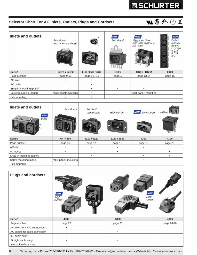
• For “cold” connections 70˚ C, Protection Class I or II• Screw mount from front or rear, or snap-in mount from front• 6100, 6102: solder terminals .138 x .032" (3.5 x 0.8mm) or quick-
connect terminals .187 x .032" (4.8 x 0.8mm), .250 x .032"(6.3 x 0.8mm) or 2.8 x 0.8mm (6100 snap-in only)
• 4300.0704: combination solder/quick-connect terminals .187 x .032"(4.8 x 0.8mm)
• 0.5 Nm torque required for M3 screws for screw-on type• For ac inlet with RFI filter see 5100, page 52• For insulation cover and cord retaining clamp, see page 27
6100, 6102:Material: thermoplastic, PA 6.6 (6102: UL 94V-0)Prongs and Terminals: brass, tin-plated
6100 6102UL recognition 15A/250V File #E96454 File #E96454CSA certification 15A/250V File #LR38456 File #LR38456VDE approval 10A/250V File #77561/3479, File #3173,
expert report expert reportSEMKO approval 10A/250VSEV approval 10A/250V
4300:Material: thermoplasticProngs and Terminals: brass, nickel-plated
UL recognition 15A/250V File #E132270CSA certification 15A/250V File #073690VDE approval 10A/250V File #63816SEMKO approval 10A/250VSEV approval 10A/250V
4300 Snap-in
E = solder terminals20.5mm orquick-connect23.5mm
6100/6102 Screw-on
E = solder terminals22.5mm orquick-connect25.5mm
S = panel thickness1.0, 1.2, 1.5, 2.0,2.5, 3.0mm
6100/6102 Snap-in
Standards: EN 60320; IEC 320/C14(6100, 4100); IEC 320/C18 (6102)
61006102
61006102
4300
Panel thickness:0.8-1.2mm:X = 20.3 +0.1
1.3-2.0mm:X = 20.5 +0.1
Filenumberson request
Filenumberson request
Filenumberson request
6100 / 6102 / 4300 AC Inlets for Panel Mounting
*
* 6102 snap-in has flanges on the sides
Order Numbers (type)
6100/6102 Snap-in 6100/6102 Screw-on Terminal Type 4300 Snap-in Terminal TypeClass I Class II Class I Class II Class I
6100.41XX 6102.51XX* 6100.3100 6102.3100* solder 4300.0704 solder/quick-connect
(6100-41/...) (6102-51/...) (6100-31) (6102-31) .138 x .032" (3.5 x 0.8mm) (0711) .187 x .032" (4.8 x 0.8mm)6100.42XX 6102.52XX* 6100.3200 6102.3200* quick-connect
(6100-42/...) (6102-52/...) (6100-32) (6102-32) .187 x .032" (4.8 x 0.8mm)6100.43XX 6102.53XX* 6100.3300 6102.3300* quick-connect(6100-43/...) (6102-53/...) (6100-33) (6102-33) .250 x .032" (6.3 x 0.8mm)XX = panel thickness 1.0, 1.2, 1.5, 2.0, 2.5, 3.0mm (e.g. 6100.4110 = 1.0mm)To order rivet mount type, change the fifth digit in the part number from a "3" to a "9" (e.g. 6100.9100, 6102.9100). *Contact Schurter for order minimum
Schurter, Inc. • Phone 707-778-6311 • Fax 707-778-6401 • E-mail [email protected] • Website http://www.schurterinc.com12
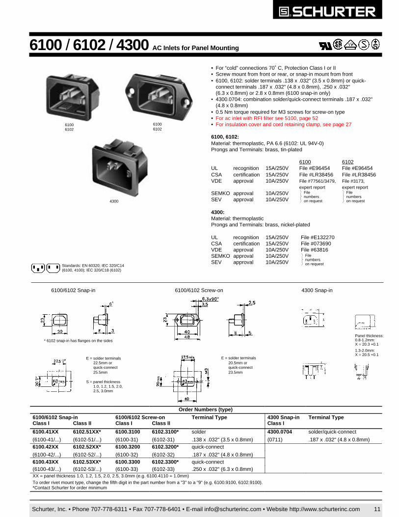
• For cold connections 70˚ C, Protection Class I• Metal shield safeguards equipment against radiated EMI
(electromagnetic interference). Flexible steel claws make multiplecontact points on the panel to ensure shield integrity.
• New snap-in design for rear panel mounting allows terminals to bepre-wired before mounting (see diagrams below)
• Solder/quick-connect terminals .187 x .032" (4.8 x 0.8mm)• For shielded inlet with line filter see GRF4, page 53
UL recognition 15A/250V File #E96454CSA certification 15A/250V File #LR38456VDE approval 10A/250V File #100875SEMKO approval 10A/250VSEV approval 10A/250V
GRF2 AC Inlet With EMI Shield – For Panel Mounting
Filenumberson request
Ground terminal
)retliftuohtiw(2FRG
slanimretdnadleihslatemhguorhtdnuorG ylnodleihslatemhguorhtdnuorG ssenkcihtlenaP slanimreT
11.2130.2FRG 11.2120.2FRG mm2.1tcennoc-kciuq/redlos
mm8.0x8.411.5130.2FRG 11.5120.2FRG mm5.1
11.0230.2FRG 11.0220.2FRG mm0.2
Standards: UL 1283; CSA C22.2/8; IEC 320/C14; EN 60320; EN133200
Order Numbers
1.Slide slotover panel
2.Press up 3.Push forward 4.Snap into place
EMI shield
NEW
Panel cut-out
Mounting Instructions
10 100 1000
110
100
90
80
70
60
50
Frequency (MHz)
Sh
ield
ing
Eff
ecti
ven
ess
(dB
)
Data is representative only. Specific measurements may vary due to differences in form, fit, function and various filter types available on the market.
Effect of Shield Attenuation
10
0
Electric FieldConventional IEC 320 InletGRF 2
Schurter, Inc. • Phone 707-778-6311 • Fax 707-778-6401 • E-mail [email protected] • Website http://www.schurterinc.com 13
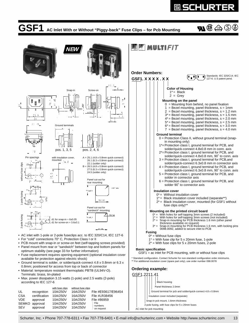
GSF1 AC Inlet With or Without “Piggy-back” Fuse Clips – for Pcb Mounting
• AC inlet with 1-pole or 2-pole fuseclips acc. to IEC 320/C14, IEC 127-6• For “cold” connections 70° C, Protection Class I or II• PCB mount with snap-in or screw-on feet (self-tapping screws provided)• Panel mount from rear or "sandwich" between top and bottom panels for
optimum stability (see page 33 for further information)• Fuse replacement requires opening equipment (optional insulation cover
available for protection against electric shock)• Ground terminal is solder, or solder/quick-connect 4.8 x 0.8mm or 6.3 x
0.8mm; positioned for access from top or back of connector• Material: temperature resistant thermoplatic PBTB (UL94V-O).
Terminals: brass, tin-plated• Max. power dissipation 3.15 watts (1-pole) and 2.5 watts (2-pole)
according to IEC 127-6
with fuse clips without fuse clips
UL recognition 10A/250V 16A/250V File #E93617/E96454CSA certification 10A/250V 16A/250V File #LR38456VDE approval 10A/250V 10A/250V File #86959SEMKO approval 10A/250V 10A/250VSEV approval 10A/250V 10A/250V
Ground terminals
with insulation cover,mounted
A = 25.1 (4.8 x 0.8mm quick-connect)26.1 (6.3 x 0.8mm quick-connect)22.1 (solder only)
B = 26.5 (4.8 x 0.8mm quick-connect)27.5 (6.3 x 0.8mm quick-connect)24.5 (solder only)
Pin spacings
Panel cut-out for“sandwich” mounting
Panel cut-out forrear mounting
d1 for snap-in = 6±0.05d1 for screw-on = 3.6±0.1
pos. 1, 3, 5 pos. 2, 4, 6
Filenumberson request
Screw-onSnap-inColor of Housing
1* = Black2 = Grey
GSF1. X X X X . X X
Mounting on the panel0 = Mounting from behind, no panel fixation1 = Bezel mounting, panel thickness, s = 1mm2 = Bezel mounting, panel thickness, s = 1.2 mm3* = Bezel mounting, panel thickness, s = 1.5 mm4* = Bezel mounting, panel thickness, s = 2.0 mm5* = Bezel mounting, panel thickness, s = 2.5 mm6* = Bezel mounting, panel thickness, s = 3.0 mm7 = Bezel mounting, panel thickness, s = 4.0 mm
Ground terminal0 = Protection Class II, without ground terminal (snap-
in mounting only)1*= Protection class I, ground terminal for PCB, and
solder/quick-connect 4.8x0.8 mm in conn. axis2*= Protection class I, ground terminal for PCB, and
solder/quick-connect 4.8x0.8 mm, 90˚ to conn. axis3 = Protection class I, ground terminal for PCB,and
solder/quick-connect 6.3x0.8 mm in connector axis4 = Protection class I, ground terminal for PCB, and
solder/quick-connect 6.3x0.8 mm, 90˚ to conn. axis5 = Protection class I, ground terminal for PCB, and
solder in connector axis6 = Protection class I, ground terminal for PCB, and
solder 90˚ to connector axis
Insulation cover0* = Without insulation cover1* = Black insulation cover included (separate**)2* = Black insulation cover, mounted (for GSF1 without
fuse clips only)**
Fusing0* = Without fuse clips1* = With fuse clip for 5 x 20mm fuse, 1-pole2* = With fuse clips for 5 x 20mm fuses, 2-pole
* Standard configuration. Contact Schurter for non-standard configuration order minimums.** For additional insulation cover (spare part only), use order number 098.0078
Basic specificationGSF1 = ac inlet for PCB mounting, with or without fuse clips
AC inlet for pcb mounting
Ordering example:GSF1.2211.41
2-pole fusing, with fuse clips for 5 x 20mm fuses
Snap-in pcb mount, 1.6mm thickness
Insulation cover included (separate)
Ground terminal for pcb and solder/quick-connect 4.8 x 0.8mm
Panel thickness 2.0mm
Black housing
Order Numbers:Standards: IEC 320/C14; IEC127-6. U.S patent pend.
with
out f
use
clip
s1-
pole
fusi
ng2-
pole
fusi
ng
NEW
Mounting on the printed circuit board0* = With holes for self-tapping 3mm screws (2 included)1* = With holes for self-tapping 3mm screws (not included)2* = Snap-in mounting for PCB thickness 1.6 mm (other panel
thickness available on request)3* = Snap-in mounting for PCB thickness 1.6 mm, with locking pins
0098.0092, added to secure inlet to PCB
Schurter, Inc. • Phone 707-778-6311 • Fax 707-778-6401 • E-mail [email protected] • Website http://www.schurterinc.com14
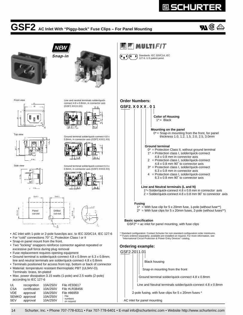
GSF2 AC Inlet With “Piggy-back” Fuse Clips – For Panel Mounting
• AC inlet with 1-pole or 2-pole fuseclips acc. to IEC 320/C14, IEC 127-6• For “cold” connections 70° C, Protection Class I or II• Snap-in panel mount from the front.• Two "locking" snappers reinforce connector against repeated or
excessive pull force during plug removal• Fuse replacement requires opening equipment• Ground terminal is solder/quick-connect 4.8 x 0.8mm or 6.3 x 0.8mm;
line and neutral terminals are solder/quick-connect 4.8 x 0.8mm• Terminals positioned for access from top, bottom or back of connector• Material: temperature resistant thermoplatic PBT (UL94V-O).
Terminals: brass, tin-plated• Max. power dissipation 3.15 watts (1-pole) and 2.5 watts (2-pole)
according to IEC 127-6
UL recognition 10A/250V File #E93617CSA certification 10A/250V File #LR38456VDE approval 10A/250V File #86959SEMKO approval 10A/250VSEV approval 10A/250V
Standards: IEC 320/C14; IEC127-6. U.S patent pend.
Front view
Top view
Side view
Line and neutral terminals solder/quick-connect 4.8 x 0.8mm, in connector axis(GSF2.XX1X.XX)
Ground terminal solder/quick-connect 6.3 x0.8mm, in connector axis (GSF2.XXX3.XX)
Ground terminal solder/quick-connect 4.8 x0.8mm, in connector axis (GSF2.XXX1.XX)
Drilledcut-out
Panelcut-out
NEWSnap-in
Ordering example:GSF2.2011.01
Ground terminal solder/quick-connect 4.8 x 0.8mm
Snap-in mounting from the front
Black housing
Line and Neutral terminals solder/quick-connect 4.8 x 0.8mm
2-pole fusing, with fuse clips for 5 x 20mm fuses *
AC inlet for panel mounting
* Standard configuration. Contact Schurter for non-standard configuration order minimums.** Fuses ordered separately; available pre-installed on request. For more information, see
“International Circuit Protection & Power Entry Devices” catalog.
GSF2. X 0 X X . 0 1Order Numbers:
Basic specificationGSF2* = ac inlet for panel mounting, with fuse clips
Fusing1* = With fuse clip for 5 x 20mm fuse, 1-pole (without fuse**)2* = With fuse clips for 5 x 20mm fuses, 2-pole (without fuses**)
Line and Neutral terminals (L and N)1*= Solder/quick-connect 4.8 x 0.8 mm in connector axis2 = Solder/quick-connect 4.8 x 0.8 mm 90˚ to connector axis
Ground terminal0* = Protection Class II, without ground terminal1* = Protection class I, solder/quick-connect
4.8 x 0.8 mm in connector axis2 = Protection class I, solder/quick-connect
4.8 x 0.8 mm 90˚ to connector axis3* = Protection class I, solder/quick-connect
6.3 x 0.8 mm in connector axis4 = Protection class I, solder/quick-connect
6.3 x 0.8 mm 90˚ to connector axis
Mounting on the panel0* = Snap-in mounting from the front, for panel
thickness 1.0, 1.2, 1.5, 2.0, 2.5, 3.0mm
Color of Housing1* = Black
Filenumberson request
25.4
±0
25.4
±0
33±0.1 33±0.1

Schurter, Inc. • Phone 707-778-6311 • Fax 707-778-6401 • E-mail [email protected] • Website http://www.schurterinc.com 15
6600 / 4721 / 4300 AC Outlets For Pcb or Panel Mounting
• For “cold” connections 70˚C, Protection Class I• Screw mount from front or rear, or snap-in mount from front• 0.5 Nm torque required for M3 screws for screw-on types
6600 for panel mounting• Solder terminals .138 x .032" (3.5 x 0.8mm) or quick-connect terminals
.187 x .032" (4.8 x 0.8mm) or .250 x .032" (6.3 x 0.8mm)• Material: thermoplastic, Polyamid 6.6; prongs and terminals: brass, tin-plated• For insulation cover, see page 27
UL recognition 15A/250V File #E103791CSA certification 15A/250V File #LR38456VDE approval 10A/250V File #2772, expert reportSEMKO, SEV appr. 10A/250V documents on request
4721 / 4724 shuttered outlets for panel mounting• Solder terminals, quick-connect 4.8mm or quick-connect 6.3mm only• Material: modified PPO (UL 94V-0)• Contacts: brass, bright electro-tin plated
UL recognition 10A/250V File #E83589(M)CSA certification 10A/250V File #056242X0000VDE approval 10A/250V File #80642CULUS (UL recognition for UL and Canada) 15A/250V pending
4300 for pcb mounting• Right angle pcb mount with screw-on panel mount from rear (wave solderable
and washable in aqueous solutions)• Combination solder/quick-connect terminals .187 x .032" (4.8 x 0.8mm)• Material: thermoplastic (UL 94V-O); prongs and terminals: brass, nickel-plated
UL recognition 15A/250V File #E93616CSA certification 15A/250V File #LR70111VDE approval 10A/250V File #1930, expert reportSEMKO, SEV appr. 10A/250V documents on request
XX=panel thickness1.0, 1.2, 1.5, 2.0, 2.5, 3.0mm (e.g. 6600.4110=1.0mm).To order rivet mount types for 6600, change the fifth digit in the part number from a “3” to a “9” (e.g. 6600.9100, etc.)* Contact Schurter, Inc. for order minimum.
Order Numbers (type)
6600 4724 4721 Terminal 4300 TerminalSnap-in Screw-on Terminal Type Snap-in (1.5mm) Screw-on Type Screw-on Type6600.41XX 6600.3100 solder 4724.0300 4721.0300 solder only 4300.0251 solder pcb(6600-41/...) (6600-31) .138” x .032” (3.5 x 0.8mm) shuttered shuttered (P675PC)6600.42XX* 6600.3200* quick-connect 4724.0100 4721.0100 quick-connect(6600-42/...) (6600-32) .187” x .032” (4.8 x 0.8mm) shuttered shuttered 4.8mm6600.43XX 6600.3300 quick connect 4724.0000 4721.0000 quick-connect,(6600-43/...) (6600-33) .250” x .032” (6.3 x 0.8mm) shuttered shuttered 6.3mm
Standards: EN 60320; IEC 320/F/H
43004721
66006600
NEWShuttered outlet 4724
6600 Snap-in
E = 24.1 solder, 27.5 quick-connect (6.3 x 0.8mm)or 26.5 quick-connect (4.8 x 0.8mm)
6600 Screw-on
PANEL CUT-OUT
- 32.2- 30.5- 28.4
6.3 TABS4.8 TABSSOLDER
2 HOLES32.5 ø3.50
24.8
4.040.0
2.5000
E
49.040.0
6.0
30.0
2 holes for ø3.5C'SK ø6.3 x 90˚
'A'
4721 Screw-on
E = 24.1 solder, 27.5 quick-connect (6.3 x 0.8mm)or 26.5 quick-connect (4.8 x 0.8mm)
S = panel thickness 1.0,1.2, 1.5, 2.0, 2.5, 3.0mm
PANEL CUT-OUT
6.3 TABS4.8 TABSSOLDER
- 32.2- 30.5- 28.4
A
SHUTTERS OPENEDBY PLUG INSERTION
32.5 MIN
28.0
35.0
E
S
2.5000
24.8 +0.20- 0.00
4.00
SHUTTERSCLOSED
SHUTTERS OPENEDBY PLUG INSERTION
Shutter operation 'A'
10.3
4300 pcb mount
4724 Snap-in
Schurter, Inc. • Phone 707-778-6311 • Fax 707-778-6401 • E-mail [email protected] • Website http://www.schurterinc.com 15a
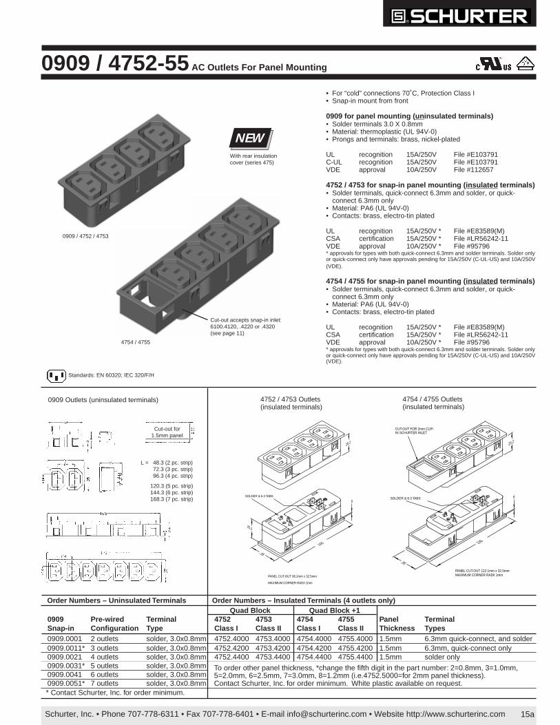
0909 / 4752-55 AC Outlets For Panel Mounting
Standards: EN 60320; IEC 320/F/H
S
126
35
PANEL CUT-OUT 122.1mm x 32.5mmMAXIMUM CORNER RADII 1mm
SOLDER & 6.3 TABS
25.2
CUT-OUT FOR 2mm CLIP-IN SCHURTER INLET
Order Numbers – Uninsulated Terminals Order Numbers – Insulated Terminals (4 outlets only)
* Contact Schurter, Inc. for order minimum.
Quad Block Quad Block +10909 Pre-wired Terminal 4752 4753 4754 4755 Panel TerminalSnap-in Configuration Type Class I Class II Class I Class II Thickness Types0909.0001 2 outlets solder, 3.0x0.8mm 4752.4000 4753.4000 4754.4000 4755.4000 1.5mm 6.3mm quick-connect, and solder0909.0011* 3 outlets solder, 3.0x0.8mm 4752.4200 4753.4200 4754.4200 4755.4200 1.5mm 6.3mm, quick-connect only0909.0021 4 outlets solder, 3.0x0.8mm 4752.4400 4753.4400 4754.4400 4755.4400 1.5mm solder only0909.0031* 5 outlets solder, 3.0x0.8mm0909.0041 6 outlets solder, 3.0x0.8mm0909.0051* 7 outlets solder, 3.0x0.8mm
25.2
PANEL CUT-OUT 96.2mm x 32.5mm
MAXIMUM CORNER RADII 1mm
100
35
SOLDER & 6.3 TABS
S
25.2
To order other panel thickness, *change the fifth digit in the part number: 2=0.8mm, 3=1.0mm,5=2.0mm, 6=2.5mm, 7=3.0mm, 8=1.2mm (i.e.4752.5000=for 2mm panel thickness).Contact Schurter, Inc. for order minimum. White plastic available on request.
• For “cold” connections 70˚C, Protection Class I• Snap-in mount from front
0909 for panel mounting ( uninsulated terminals)• Solder terminals 3.0 X 0.8mm• Material: thermoplastic (UL 94V-0)• Prongs and terminals: brass, nickel-plated
UL recognition 15A/250V File #E103791C-UL recognition 15A/250V File #E103791VDE approval 10A/250V File #112657
4752 / 4753 for snap-in panel mounting ( insulated terminals)• Solder terminals, quick-connect 6.3mm and solder, or quick-
connect 6.3mm only• Material: PA6 (UL 94V-0)• Contacts: brass, electro-tin plated
UL recognition 15A/250V * File #E83589(M)CSA certification 15A/250V * File #LR56242-11VDE approval 10A/250V * File #95796* approvals for types with both quick-connect 6.3mm and solder terminals. Solder onlyor quick-connect only have approvals pending for 15A/250V (C-UL-US) and 10A/250V(VDE).
4754 / 4755 for snap-in panel mounting ( insulated terminals)• Solder terminals, quick-connect 6.3mm and solder, or quick-
connect 6.3mm only• Material: PA6 (UL 94V-0)• Contacts: brass, electro-tin plated
UL recognition 15A/250V * File #E83589(M)CSA certification 15A/250V * File #LR56242-11VDE approval 10A/250V * File #95796* approvals for types with both quick-connect 6.3mm and solder terminals. Solder onlyor quick-connect only have approvals pending for 15A/250V (C-UL-US) and 10A/250V(VDE).
NEWWith rear insulationcover (series 475)
Cut-out accepts snap-in inlet:6100.4120, .4220 or .4320(see page 11)
4754 / 4755
0909 / 4752 / 4753
4752 / 4753 Outlets(insulated terminals)
0909 Outlets (uninsulated terminals)
120.3 (5 pc. strip)144.3 (6 pc. strip)168.3 (7 pc. strip)
L = 48.3 (2 pc. strip)72.3 (3 pc. strip)96.3 (4 pc. strip)
4754 / 4755 Outlets(insulated terminals)
Cut-out for1.5mm panel
Schurter, Inc. • Phone 707-778-6311 • Fax 707-778-6401 • E-mail [email protected] • Website http://www.schurterinc.com16
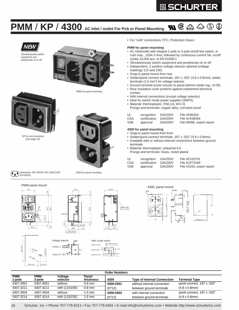
PMM / KP / 4300 AC Inlet / outlet For Pcb or Panel Mounting (VDE)
KP for pcb mounting(see page 33)
Standards: IEC 60536; IEC 320/C14/F;EN 60320
Order NumbersPMM 1-pole
PMM 2-pole
Voltage selector
Panel thickness 4300 Type of Internal Connection Terminal Type
4307.3001 4307.4001 without 0.8 mm 4300.0301 without internal connection quick-connect .187 x .032" 4307.3211 4307.4211 with (115/230) 0.8 mm (0712) between ground terminals (4.8 x 0.8mm)
4307.3004 4307.4004 without 1.5 mm 4300.0303 with internal connection quick-connect .187 x .032" 4307.3214 4307.4214 with (115/230) 1.5 mm (0712) between ground terminals (4.8 x 0.8mm)
8.2
16.317.46
33.74
solder lugsfor 1.5 mm2
2
15.4
63.5
1.29.
2
26.2 7.2
13.44 S±0.05
S = Panel thicknesssee technical data
4.8x0.8
32
21.3
64.7
66.7
0.8
1.2
7.5
15.5
∅ 4
+0.0
50
R 3.7
Position A
Position B
jumper
230
115
230
115 12
Voltage selector
Appliance-inlet
Appliance-outlet
NPEL
NPEL
PE’
N’
L’
PMM panel mount 4300, panel mount
32.2±0.1 5.2±0.1
63.7
±0.
1
15.6
±0.
1
R1 max.
∅ 4+0.050
Voltage selector With 2-pole switch
• For “cold” connections 70˚C, Protection Class I
PMM for panel mounting• AC inlet/outlet with integral 1-pole or 2-pole on/off line switch, in
rush max., 100A 3-4ms, followed by continuous current 5A, on/offcycles 10,000 acc. to EN 61058-1
• Simultaneously switch equipment and peripherals on or off• Independent, 2 position voltage selector optional (voltage
markings 115 and 230)• Snap-in panel mount from rear• Solder/quick-connect terminals .187 x .032" (4.8 x 0.8mm); solder
terminals (1.5 mm2) for voltage selector• Ground terminal screw mounts to panel (ø4mm solder lug, +0.05)• Rear insulation cover protects against inadvertent electrical
contact• With internal connections (except voltage selector)• Ideal for switch mode power supplies (SMPS)• Material: thermoplastic, PA6 (UL 94V-0)
Prongs and terminals: copper-alloy, corrosion proof
UL recognition 10A/250V File #E96454CSA certification 10A/250V File #LR38456VDE approval 10A/250V File #6090, expert report
4300 for panel mounting• Snap-in panel mount from front• Solder/quick-connect terminals .187 x .032" (4.8 x 0.8mm)• Available with or without internal connections between ground
terminals• Material: thermoplastic, polyamid 6.6
Prongs and terminals: brass, nickel-plated
UL recognition 10A/250V File #E103791CSA certification 10A/250V File #LR73165VDE approval 10A/250V File #3193, expert report
PMM for panel mounting
NEWSimultaneously switchequipment andperipherals on or off
4300 for panel mounting
Schurter, Inc. • Phone 707-778-6311 • Fax 707-778-6401 • E-mail [email protected] • Website http://www.schurterinc.com 17
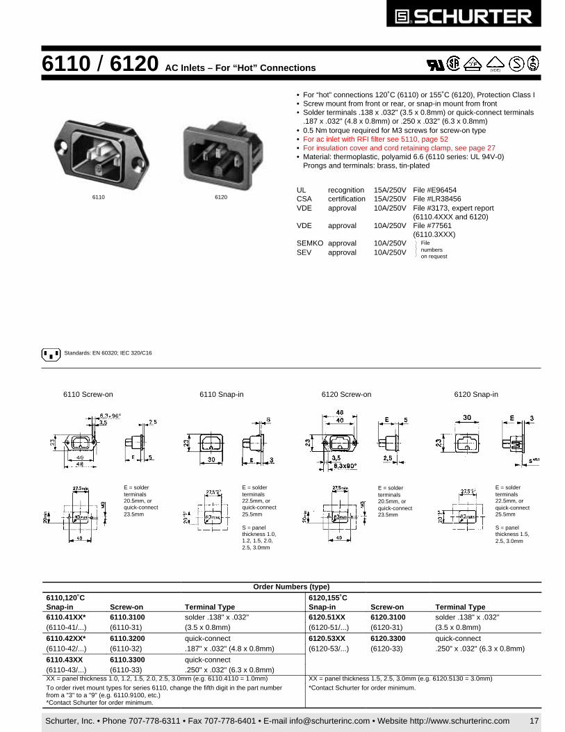
6110 / 6120 AC Inlets – For “Hot” Connections
• For “hot” connections 120˚C (6110) or 155˚C (6120), Protection Class I• Screw mount from front or rear, or snap-in mount from front• Solder terminals .138 x .032" (3.5 x 0.8mm) or quick-connect terminals
.187 x .032" (4.8 x 0.8mm) or .250 x .032" (6.3 x 0.8mm)• 0.5 Nm torque required for M3 screws for screw-on type• For ac inlet with RFI filter see 5110, page 52• For insulation cover and cord retaining clamp, see page 27• Material: thermoplastic, polyamid 6.6 (6110 series: UL 94V-0)
Prongs and terminals: brass, tin-plated
UL recognition 15A/250V File #E96454CSA certification 15A/250V File #LR38456VDE approval 10A/250V File #3173, expert report
(6110.4XXX and 6120)VDE approval 10A/250V File #77561
(6110.3XXX)SEMKO approval 10A/250VSEV approval 10A/250V
E = solderterminals22.5mm, orquick-connect25.5mm
S = panelthickness 1.5,2.5, 3.0mm
E = solderterminals20.5mm, orquick-connect23.5mm
E = solderterminals20.5mm, orquick-connect23.5mm
E = solderterminals22.5mm, orquick-connect25.5mm
S = panelthickness 1.0,1.2, 1.5, 2.0,2.5, 3.0mm
6110 Screw-on 6110 Snap-in 6120 Screw-on 6120 Snap-in
Order Numbers (type)
6110,120˚C Snap-in Screw-on Terminal Type
6120,155˚CSnap-in Screw-on Terminal Type
6110.41XX* 6110.3100 solder .138" x .032" 6120.51XX 6120.3100 solder .138" x .032"(6110-41/...) (6110-31) (3.5 x 0.8mm) (6120-51/...) (6120-31) (3.5 x 0.8mm)
6110.42XX* 6110.3200 quick-connect 6120.53XX 6120.3300 quick-connect(6110-42/...) (6110-32) .187" x .032" (4.8 x 0.8mm) (6120-53/...) (6120-33) .250" x .032" (6.3 x 0.8mm)
6110.43XX 6110.3300 quick-connect(6110-43/...) (6110-33) .250" x .032" (6.3 x 0.8mm)XX = panel thickness 1.0, 1.2, 1.5, 2.0, 2.5, 3.0mm (e.g. 6110.4110 = 1.0mm) XX = panel thickness 1.5, 2.5, 3.0mm (e.g. 6120.5130 = 3.0mm)To order rivet mount types for series 6110, change the fifth digit in the part numberfrom a "3" to a "9" (e.g. 6110.9100, etc.) *Contact Schurter for order minimum.
*Contact Schurter for order minimum.
6110 6120
Standards: EN 60320; IEC 320/C16
(VDE)
Filenumberson request
Schurter, Inc. • Phone 707-778-6311 • Fax 707-778-6401 • E-mail [email protected] • Website http://www.schurterinc.com18
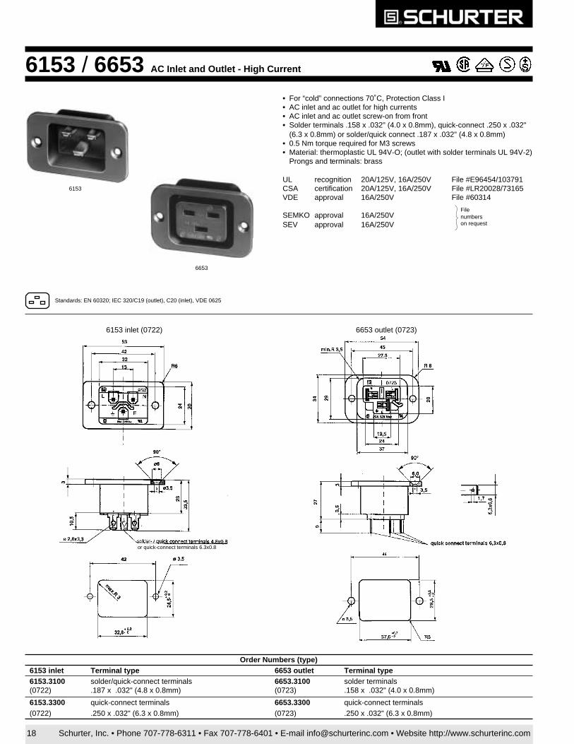
Order Numbers (type)6153 inlet Terminal type 6653 outlet Terminal type6153.3100 solder/quick-connect terminals 6653.3100 solder terminals(0722) .187 x .032" (4.8 x 0.8mm) (0723) .158 x .032" (4.0 x 0.8mm)
6153.3300 quick-connect terminals 6653.3300 quick-connect terminals(0722) .250 x .032" (6.3 x 0.8mm) (0723) .250 x .032" (6.3 x 0.8mm)
6153 / 6653 AC Inlet and Outlet - High Current
Filenumberson request
• For “cold” connections 70˚C, Protection Class I• AC inlet and ac outlet for high currents• AC inlet and ac outlet screw-on from front• Solder terminals .158 x .032" (4.0 x 0.8mm), quick-connect .250 x .032"
(6.3 x 0.8mm) or solder/quick connect .187 x .032" (4.8 x 0.8mm)• 0.5 Nm torque required for M3 screws• Material: thermoplastic UL 94V-O; (outlet with solder terminals UL 94V-2)
Prongs and terminals: brass
UL recognition 20A/125V, 16A/250V File #E96454/103791CSA certification 20A/125V, 16A/250V File #LR20028/73165VDE approval 16A/250V File #60314
SEMKO approval 16A/250VSEV approval 16A/250V
Standards: EN 60320; IEC 320/C19 (outlet), C20 (inlet), VDE 0625
6153 inlet (0722) 6653 outlet (0723)
6653
6153
or quick-connect terminals 6.3x0.8
Schurter, Inc. • Phone 707-778-6311 • Fax 707-778-6401 • E-mail [email protected] • Website http://www.schurterinc.com 19
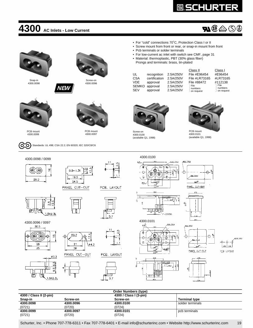
• For “cold” connections 70˚C, Protection Class I or II• Screw mount from front or rear, or snap-in mount from front• Pcb terminals or solder terminals• For low-current ac inlet with switch see CMF, page 31• Material: thermoplastic, PBT (30% glass fiber)
Prongs and terminals: brass, tin-plated
Class II Class IUL recognition 2.5A/250V File #E96454 #E96454CSA certification 2.5A/250V File #LR73165 #LR73165VDE approval 2.5A/250V File #88472 #112138SEMKO approval 2.5A/250VSEV approval 2.5A/250V
4300 AC Inlets - Low Current
Filenumberson request
Filenumberson request
PCB mount4300.0099
PCB mount4300.0097
Screw-on4300.0096
Snap-in4300.0098
NEW
Screw-on4300.0100(available Q1, 1998)
PCB mount4300.0101(available Q1, 1998)
Standards: UL 498; CSA 22.2; EN 60320; IEC 320/C8/C6
4300.0101
4300.0100
4300.0096 / 0097
4300.0098 / 0099
)epyt(srebmuNredrO)nip-2(IIssalC/0034
ni-panS no-wercS)nip-3(IssalC/0034
no-wercS epytlanimreT8900.0034 6900.0034 0010.0034 slanimretredlos
)1270( )0270( )4270(9900.0034 7900.0034 1010.0034 slanimretbcp
)1270( )0270( )4270(
Schurter, Inc. • Phone 707-778-6311 • Fax 707-778-6401 • E-mail [email protected] • Website http://www.schurterinc.com20
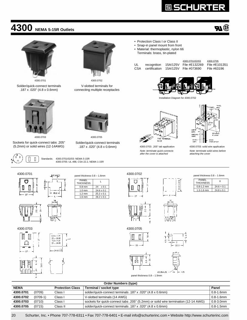
4300 NEMA 5-15R Outlets
• Protection Class I or Class II• Snap-in panel mount from front• Material: thermoplastic, nylon 66
Terminals: brass, tin-plated
4300.0701/02/03 4300.0705
UL recognition 15A/125V File #E132269 File #E101351CSA certification 15A/125V File #073690 File #63196
4300.0701
Solder/quick-connect terminals.187 x .020" (4.8 x 0.6mm)
4300.0702
V-slotted terminals forconnecting multiple receptacles
Solder/quick-connect terminals.187 x .020" (4.8 x 0.6mm)
4300.07054300.0703
Sockets for quick-connect tabs .205"(5.2mm) or solid wires (12-14AWG)
PANELTHICKNESS
L
0.8 mm 24 ± 0.1
1.0 mm 24.6 ± 0.11.2 mm 25.2 ± 0.1 1.6 mm 26.2 ± 0.1
panel thickness 0.8 – 1.6mm
PANELTHICKNESS
X
0.8-1.2 mm 24.6 + 0.1
1.3-1.6 mm 24.8 ± 0.1
panel thickness 0.8 – 1.6mm
panel thickness 0.8 – 1.5mm
4300.0701 4300.0702
4300.0703 4300.0705
Order Numbers (type)NEMA Protection Class Terminal / socket type Panel4300.0701 (0709) Class I solder/quick-connect terminals .187 x .020" (4.8 x 0.6mm) 0.8-1.6mm
4300.0702 (0709-1) Class I V-slotted terminals (14 AWG) 0.8-1.6mm4300.0703 (0710) Class I sockets for quick-connect tabs .205" (5.2mm) or solid wire termination (12-14 AWG) 0.8-3.0mm
4300.0705 (0715) Class II solder/quick-connect terminals .187 x .020" (4.8 x 0.6mm) 0.8-1.5mm
Standards: 4300.0701/02/03: NEMA 5-15R4300.0705: UL 498, CSA 22.2, NEMA 1-15R
4300.0703: .205" tab application
Note: terminate quick-connectsafter the cover is attached
4300.0703: solid wire application
Note: terminate solid wires beforeattaching the cover
Installation Diagram for 4300.0702
Schurter, Inc. • Phone 707-778-6311 • Fax 707-778-6401 • E-mail [email protected] • Website http://www.schurterinc.com 21
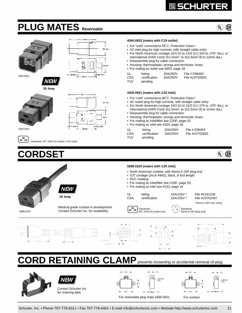
PLUG MATES Rewireable
4300.0922 (mates with C19 outlet)
• For “cold” connections 65˚C, Protection Class I• AC inlet plug for high currents, with straight cable entry• For North American cordage 16/3 SJ to 12/3 SJ (.325 to .475" dia.), or
International (HAR Cord) 3x1.5mm2 to 3x2.5mm2 (8 to 12mm dia.)• Disassemble plug for cable connection• Housing: thermoplastic; prongs and terminals: brass• For mating ac outlet see 6653, page 18
UL listing 20A/250V File # E96454CSA certification 20A/250V File #LR702825TUV pending
4300.0921 (mates with C20 inlet)
• For “cold” connections 65˚C, Protection Class I• AC outlet plug for high currents, with straight cable entry• For North American cordage 16/3 SJ to 12/3 SJ (.275 to .475" dia.), or
International (HAR Cord) 3x1.5mm2 to 3x2.5mm2 (8 to 12mm dia.)• Disassemble plug for cable connection• Housing: thermoplastic; prongs and terminals: brass• For mating ac inlet/filter see C20F, page 53• For mating ac inlet see 6153, page 18
UL listing 20A/250V File # E96454CSA certification 20A/250V File #LR702825TUV pending
®
4300.0922
4300.0921
NEW20 Amp
CORD RETAINING CLAMP prevents loosening or accidental removal of plug
NEWContact Schurter Inc.for ordering data
CORDSET ®
0888.0220 (mates with C20 inlet)
• North American cordset, with Nema 5-15P plug end• SJT cordage (3x14 AWG), black, 8 foot length• PVC molding• For mating ac inlet/filter see C20F, page 53.• For mating ac inlet see 6153, page 18
UL listing 15A/125V * File #E191239CSA certification 15A/125V * File #LR702497
* Nema 5-15P max. rating
0888.0220
NEW20 Amp
Standards:IEC 320/C19 (outlet end)
Standards:Nema 5-15P (plug end)
Medical grade cordset in development.Contact Schurter Inc. for availability.
Standards: IEC 320/C19 (outlet), /C20 (inlet)
CAPTIVENUT
12.72.5
6.434.0
25.7
43.2
CAPTIVENUT
12.73.0
6.432.1
24.1
43.2
For rewireable plug mate 4300.0921 For cordset
Schurter, Inc. • Phone 707-778-6311 • Fax 707-778-6401 • E-mail [email protected] • Website http://www.schurterinc.com22
49.8
70.0
44.5
21.6
28.7
O8.5mm for 14 AWG or 1.5 mm2
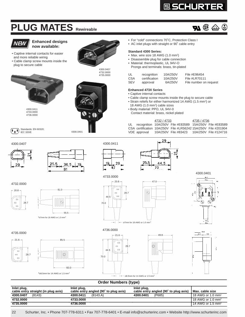
PLUG MATES Rewireable
Order Numbers (type)Inlet plug,cable entry straight (in plug axis)
Inlet plug,cable entry angled (90˚ to plug axis)
Inlet plug,cable entry angled (90˚ to plug axis) Max. cable size
4300.0407 (8143) 4300.0411 (8143.A) 4300.0401 (P685) 18 AWG or 1.0 mm2
4732.0000 4733.0000 18 AWG or 1.0 mm2
4735.0000 4736.0000 14 AWG or 1.5 mm2
4736.0000
47.0
44.5
70.0
28.7
20.8
O7mm for 18 AWG or 1.0 mm 2
4733.0000
• For “cold” connections 70˚C, Protection Class I• AC inlet plugs with straight or 90˚ cable entry
Standard 4300 Series:• Max. wire size 18 AWG (1.0 mm2)• Disassemble plug for cable connection• Material: thermoplastic, UL 94V-O
Prongs and terminals: brass, tin-plated
UL recognition 10A/250V File #E96454CSA certification 10A/250V File #LR70111SEV approval 6A/250V File number on request
Enhanced 473X Series• Captive internal contacts• Cable clamp screw mounts inside the plug to secure cable• Strain reliefs for either harmonized 14 AWG (1.5 mm2) or 18 AWG (1.0 mm2) cable sizes• Body material: PPO, UL 94V-0 Contact material: brass, nickel plated
4732 / 4733 4735 / 4736UL recognition 10A/250V File #E83589 15A/250V File #E83589CSA certification 10A/250V File #LR56242 15A/250V File #201904VDE approval 10A/250V File #83423 10A/250V File #124716
NEW
• Captive internal contacts for easier and more reliable wiring• Cable clamp screw mounts inside the plug to secure cable
Enhanced designsnow available:
4300.04074732.00004735.0000
Standards: EN 60320;IEC 320/E
4300.04114733.00004736.0000
4300.0401
4300.04114300.0407
60.0
85.5
28.7
21.6
*
*O8.5mm for 14 AWG or 1.5 mm2
4735.0000
28.7
20.8 81.0
55.5
*O7mm for 18 AWG or 1.0 mm2
*
4732.0000
4300.0401
Schurter, Inc. • Phone 707-778-6311 • Fax 707-778-6401 • E-mail [email protected] • Website http://www.schurterinc.com 23
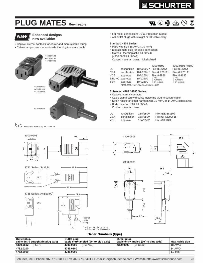
• For “cold” connections 70˚C, Protection Class I• AC outlet plugs with straight or 90˚ cable entry
Standard 4300 Series:• Max. wire size 18 AWG (1.0 mm2)• Disassemble plug for cable connection• Material: thermoplastic, UL 94V-O
(4300.0609 UL 94V-2)Contact material: brass, nickel-plated
4300.0602 4300.0606 / 0609UL recognition 10A/250V * File #E96454 File #E96454CSA certification 10A/250V * File #LR70111 File #LR70111VDE approval 10A/250V File #63826 File #69635SEMKO approval 10A/250VSEV approval 10A/250V
*4300.0609: 15A/125V, 10A/250V UL, CSA
Enhanced 4782 / 4785 Series:• Captive internal contacts• Cable clamp screw mounts inside the plug to secure cable• Strain reliefs for either harmonized 1.0 mm2, or 14 AWG cable sizes• Body material: PA6, UL 94V-0
Contact material: brass
UL recognition 15A/250V File #E83589(M)CSA certification 15A/250V File #LR56242-15VDE approval 10A/250V File #100043
PLUG MATES Rewireable
NEW Enhanced designsnow available:
®
• 4300.0609
• 4300.0606• 4785.0100• 4785.0000
Standards: EN60320; IEC 320/C13
4300.0606
4300.0609
Filenumberson request
Filenumberson request
4300.0602
61.5
87.0
*28.7
4782 Series, Straight
4785 Series, Angled 90˚
28.7
51.0
70.0
44.5
*
• 4300.0602• 4782.0100• 4782.0000
• Captive internal contacts for easier and more reliable wiring• Cable clamp screw mounts inside the plug to secure cable
Internalcableclamp
Internal cable clamp
Order Numbers (type)Outlet plug,cable entry straight (in plug axis)
Outlet plug,cable entry angled (90˚ to plug axis)
Outlet plug,cable entry angled (90˚ to plug axis) Max. cable size
4300.0602 (P587) 4300.0606 (P587SE) 4300.0609 (SFO430) 18 AWG4782.0100 4785.0100 14 AWG4782.0000 4785.0000 1.0 mm2
* ø 7 mm for 1.0mm2 cableø 8.5 mm for 14 AWG cable
Schurter, Inc. • Phone 707-778-6311 • Fax 707-778-6401 • E-mail [email protected] • Website http://www.schurterinc.com 23a
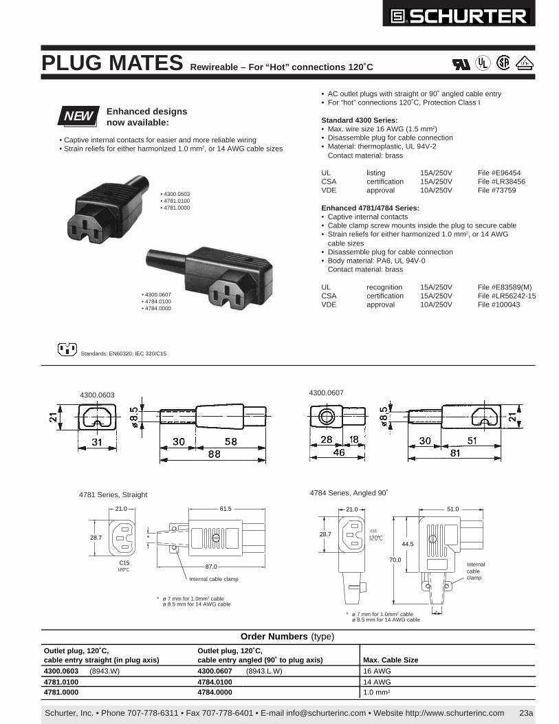
PLUG MATES Rewirea ble – For “Hot ” connections 120˚C
C15
61.5
87.0
28.7
21.0
*
4781 Series, Straight 4784 Series, Angled 90˚
C15
51.0
70.0
28.7
44.5
21.0
*
4300.0607
®
• Captive internal contacts for easier and more reliable wiring• Strain reliefs for either harmonized 1.0 mm2, or 14 AWG cable sizes
NEW Enhanced designsnow available:
Standards: EN60320; IEC 320/C15
4300.0603
• 4300.0607• 4784.0100• 4784.0000
• 4300.0603• 4781.0100• 4781.0000
Internal cable clamp
Internalcableclamp
Order Numbers (type)
Outlet plug, 120˚C,cable entry straight (in plug axis)
Outlet plug, 120˚C,cable entry angled (90˚ to plug axis) Max. Cable Size
4300.0603 (8943.W) 4300.0607 (8943.L.W) 16 AWG
4781.0100 4784.0100 14 AWG4781.0000 4784.0000 1.0 mm2
• AC outlet plugs with straight or 90˚ angled cable entry• For “hot” connections 120˚C, Protection Class I
Standard 4300 Series:• Max. wire size 16 AWG (1.5 mm2)• Disassemble plug for cable connection• Material: thermoplastic, UL 94V-2
Contact material: brass
UL listing 15A/250V File #E96454CSA certification 15A/250V File #LR38456VDE approval 10A/250V File #73759
Enhanced 4781/4784 Series:• Captive internal contacts• Cable clamp screw mounts inside the plug to secure cable• Strain reliefs for either harmonized 1.0 mm2, or 14 AWG
cable sizes• Disassemble plug for cable connection• Body material: PA6, UL 94V-0
Contact material: brass
UL recognition 15A/250V File #E83589(M)CSA certification 15A/250V File #LR56242-15VDE approval 10A/250V File #100043
* ø 7 mm for 1.0mm2 cableø 8.5 mm for 14 AWG cable
* ø 7 mm for 1.0mm2 cableø 8.5 mm for 14 AWG cable
Schurter, Inc. • Phone 707-778-6311 • Fax 707-778-6401 • E-mail [email protected] • Website http://www.schurterinc.com24
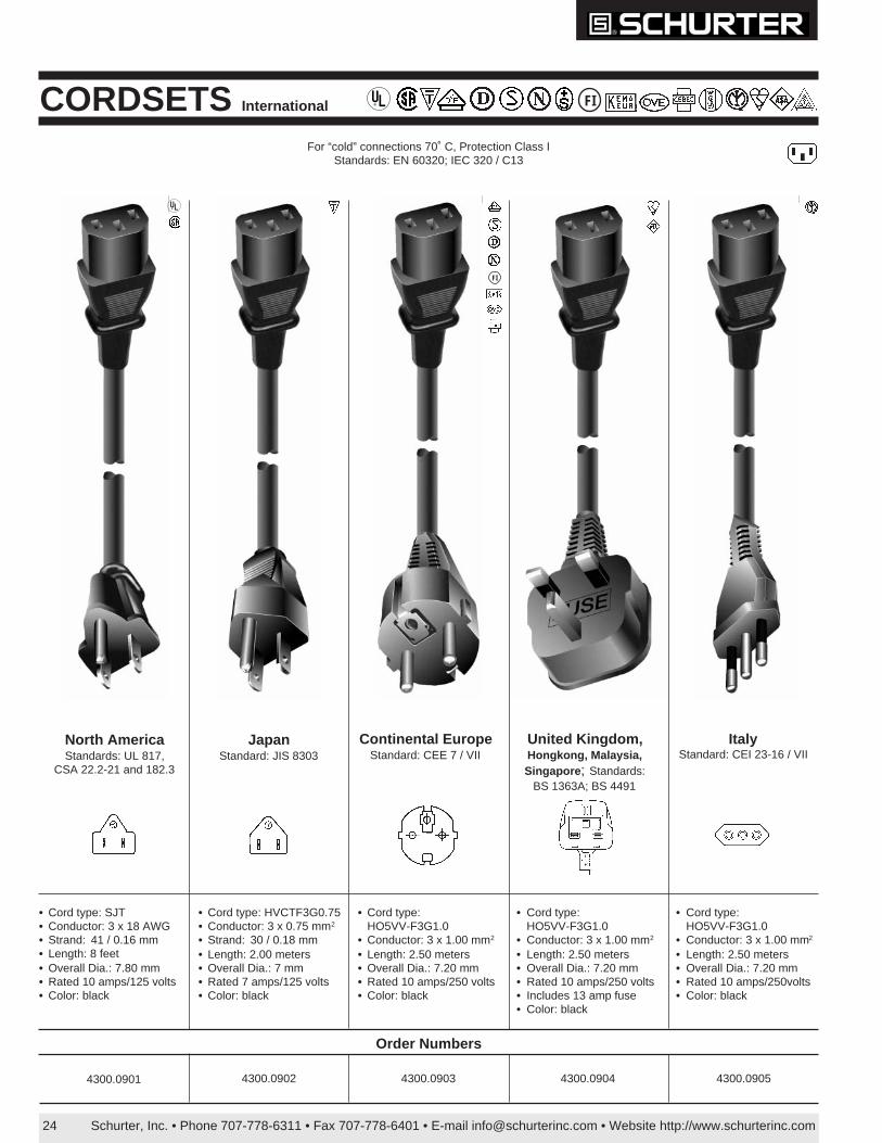
CORDSETS International
For “cold” connections 70˚ C, Protection Class IStandards: EN 60320; IEC 320 / C13
Order Numbers
FI
• Cord type: SJT• Conductor: 3 x 18 AWG• Strand: 41 / 0.16 mm• Length: 8 feet• Overall Dia.: 7.80 mm• Rated 10 amps/125 volts• Color: black
• Cord type: HVCTF3G0.75• Conductor: 3 x 0.75 mm2
• Strand: 30 / 0.18 mm• Length: 2.00 meters• Overall Dia.: 7 mm• Rated 7 amps/125 volts• Color: black
• Cord type:HO5VV-F3G1.0
• Conductor: 3 x 1.00 mm2
• Length: 2.50 meters• Overall Dia.: 7.20 mm• Rated 10 amps/250 volts• Color: black
• Cord type:HO5VV-F3G1.0
• Conductor: 3 x 1.00 mm2
• Length: 2.50 meters• Overall Dia.: 7.20 mm• Rated 10 amps/250 volts• Includes 13 amp fuse• Color: black
• Cord type:HO5VV-F3G1.0
• Conductor: 3 x 1.00 mm2
• Length: 2.50 meters• Overall Dia.: 7.20 mm• Rated 10 amps/250volts• Color: black
4300.0901 4300.0902 4300.0903 4300.0904 4300.0905
FI
North AmericaStandards: UL 817,
CSA 22.2-21 and 182.3
JapanStandard: JIS 8303
Continental EuropeStandard: CEE 7 / VII
United Kingdom,Hongkong, Malaysia,Singapore ; Standards:
BS 1363A; BS 4491
ItalyStandard: CEI 23-16 / VII
®
®
Schurter, Inc. • Phone 707-778-6311 • Fax 707-778-6401 • E-mail [email protected] • Website http://www.schurterinc.com 25
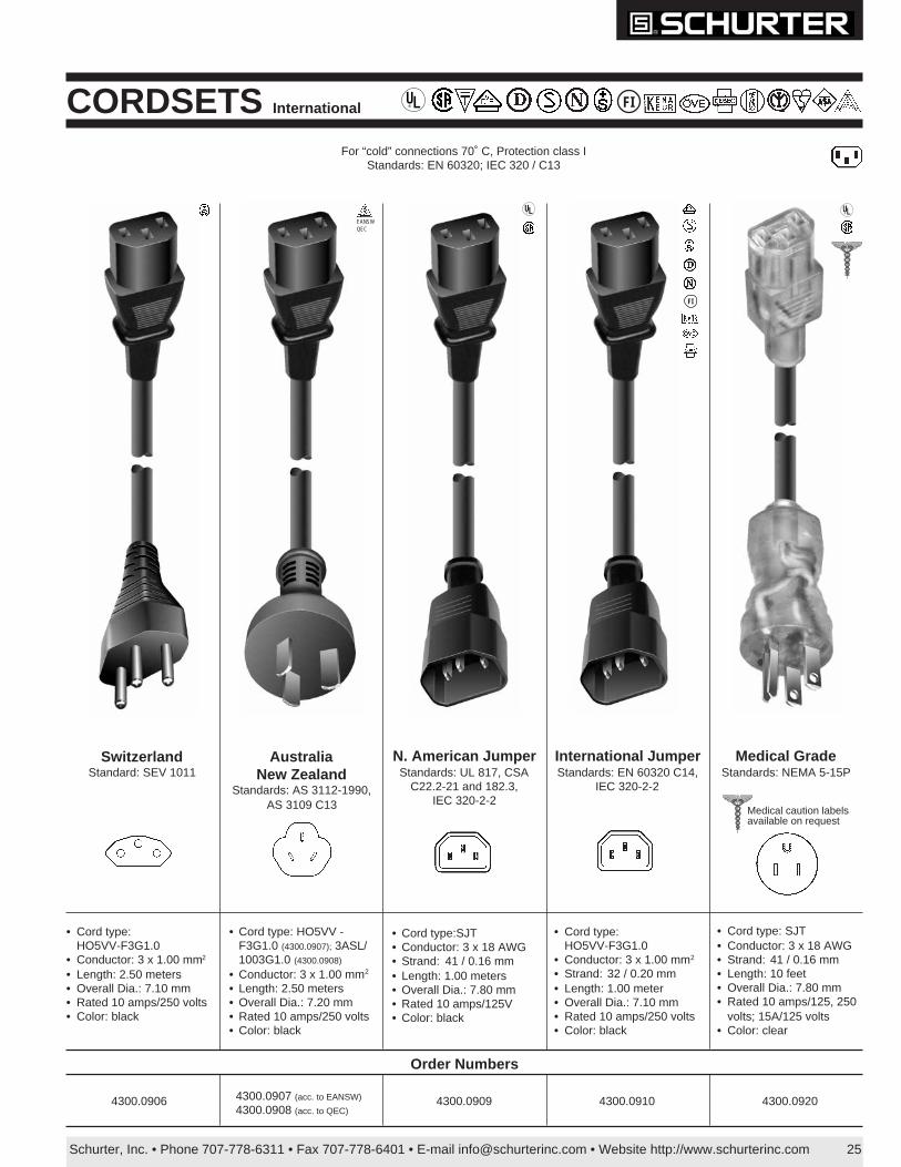
CORDSETS International
Order Numbers
4300.0906 4300.0909 4300.0910 4300.0920
EANSWQEC
• Cord type:HO5VV-F3G1.0
• Conductor: 3 x 1.00 mm2
• Length: 2.50 meters• Overall Dia.: 7.10 mm• Rated 10 amps/250 volts• Color: black
• Cord type: HO5VV -F3G1.0 (4300.0907); 3ASL/1003G1.0 (4300.0908)
• Conductor: 3 x 1.00 mm2
• Length: 2.50 meters• Overall Dia.: 7.20 mm• Rated 10 amps/250 volts• Color: black
For “cold” connections 70˚ C, Protection class IStandards: EN 60320; IEC 320 / C13
FI
4300.0907 (acc. to EANSW)
4300.0908 (acc. to QEC)
• Cord type:SJT• Conductor: 3 x 18 AWG• Strand: 41 / 0.16 mm• Length: 1.00 meters• Overall Dia.: 7.80 mm• Rated 10 amps/125V• Color: black
FI
• Cord type:HO5VV-F3G1.0
• Conductor: 3 x 1.00 mm2
• Strand: 32 / 0.20 mm• Length: 1.00 meter• Overall Dia.: 7.10 mm• Rated 10 amps/250 volts• Color: black
• Cord type: SJT• Conductor: 3 x 18 AWG• Strand: 41 / 0.16 mm• Length: 10 feet• Overall Dia.: 7.80 mm• Rated 10 amps/125, 250
volts; 15A/125 volts• Color: clear
SwitzerlandStandard: SEV 1011
AustraliaNew Zealand
Standards: AS 3112-1990,AS 3109 C13
International JumperStandards: EN 60320 C14,
IEC 320-2-2
Medical GradeStandards: NEMA 5-15P
N. American JumperStandards: UL 817, CSA
C22.2-21 and 182.3,IEC 320-2-2
®
® ®
Medical caution labelsavailable on request

Schurter, Inc. • Phone 707-778-6311 • Fax 707-778-6401 • E-mail [email protected] • Website http://www.schurterinc.com26
Cordset Equipment End Destination End Cordage ColorLength of Cable
(standard)*Rated
CurrentApprovals
CS01.0221.150C7 plug (non-polarized)mates to C8 connector Nema 1-15P
standardSPT2 Black 1500mm 7A /125V
UL #E55943SPCSA #LR035162
CS02.0221.150C7 plug (polarized)mates to C8 connector
Nema 1-15Pstandard
SPT2Black 1500mm 2.5A/250V
UL #E136285; CSA #LR86473(destination end), #LL93548(equipment end)
CS01.0121.150C7 plug (non-polarized)mates to C8 connector
EuroplugCEE 7/16 H03VVH2-F Black 1500mm 2.5A/250V
VDE, SEV, Semko, KEMA,NEMKO,OVE, CEBEC,DEMKO, SETI, UTE, IMQ
CS01.0321.150C7 plug (non-polarized)mates to C8 connector
Continental EuropeCEE 7/7
H03VVH2-F Black 1500mm 2.5A/250VVDE, Semko, NEMKO,OVE, CEBEC, SETI,UTE, KEMA
CS01.0421.150C7 plug (non-polarized)mates to C8 connector
United Kingdom BS1363
H03VVH2-F Black 1500mm 2.5A/250V ASTA (United Kingdom)
CS03.0421.150 C5 plug (polarized)mates to connector C6
United Kingdom BS1363
H03VV-F Black 1500mm 2.5A/250V ASTA (United Kingdom)
CS03.0521.150C5 plug (polarized)mates to connector C6
Schuko PlugCEE 7/7 H03VV-F Black 1500mm 2.5A/250V
VDE, Semko, NEMKO,OVE, CEBEC, SETI,UTE, KEMA
CS03.0621.150C5 plug (polarized)mates to connector C6
North AmericaNEMA 5-15P (U.S.)
standardSPT2
Black 1500mm 2.5A/250V UL, CSA
Order Numbers
CMF C8
CMF C8 (polarized)
Ordering example for cordsets:
For CMF low current inlet / switch,see page 31
FI®Cordsets Miniature, Low Current (2.5A/250V)
Continental Europe
United Kingdom
Nema (U.S. and Canada)
CMF C6
*Other cable lengths available. Contact Schurter, Inc. for minimums and lead-times.
Europlug
Schurter, Inc. • Phone 707-778-6311 • Fax 707-778-6401 • E-mail [email protected] • Website http://www.schurterinc.com 27
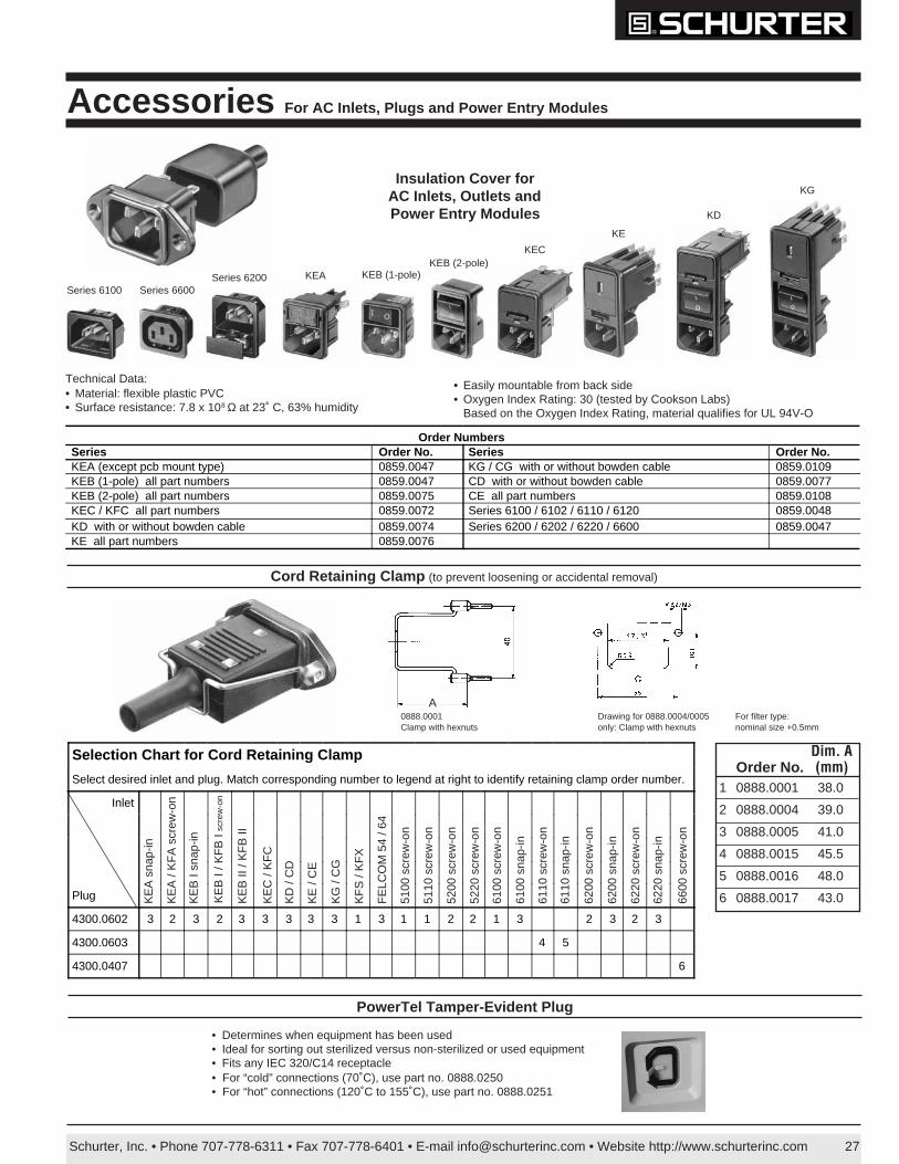
Selection Chart for Cord Retaining Clamp
Select desired inlet and plug. Match corresponding number to legend at right to identify retaining clamp order number.
Inlet
Plug
4300.0602 3 2 3 2 3 3 3 3 3 1 3 1 1 2 2 1 3 2 3 2 3
4300.0603 4 5
4300.0407 6
Insulation Cover forAC Inlets, Outlets andPower Entry Modules
Series 6100
Technical Data:• Material: flexible plastic PVC• Surface resistance: 7.8 x 10⁸ Ω at 23˚ C, 63% humidity
• Easily mountable from back side• Oxygen Index Rating: 30 (tested by Cookson Labs)
Based on the Oxygen Index Rating, material qualifies for UL 94V-O
KE
KECKEB (2-pole)
KEB (1-pole)KEASeries 6200Series 6600
KD
KG
Accessories For AC Inlets, Plugs and Power Entry Modules
Order NumbersSeries Order No. Series Order No.KEA (except pcb mount type) 0859.0047 KG / CG with or without bowden cable 0859.0109KEB (1-pole) all part numbers 0859.0047 CD with or without bowden cable 0859.0077KEB (2-pole) all part numbers 0859.0075 CE all part numbers 0859.0108KEC / KFC all part numbers 0859.0072 Series 6100 / 6102 / 6110 / 6120 0859.0048KD with or without bowden cable 0859.0074 Series 6200 / 6202 / 6220 / 6600 0859.0047KE all part numbers 0859.0076
Cord Retaining Clamp (to prevent loosening or accidental removal)
0888.0001Clamp with hexnuts
Drawing for 0888.0004/0005only: Clamp with hexnuts
For filter type:nominal size +0.5mm
KE
B I
/ KF
B I
scre
w-o
n
KE
A s
nap-
in
KE
A /
KF
A s
crew
-on
KE
B I
snap
-in
KE
B II
/ K
FB
II
KE
C /
KF
C
KD
/ C
D
KE
/ C
E
KG
/ C
G
KF
S /
KF
X
FE
LCO
M 5
4 / 6
4
5100
scr
ew-o
n
5110
scr
ew-o
n
5200
scr
ew-o
n
5220
scr
ew-o
n
6100
scr
ew-o
n
6100
sna
p-in
6110
scr
ew-o
n
6110
sna
p-in
6200
scr
ew-o
n
6200
sna
p-in
6220
scr
ew-o
n
6600
scr
ew-o
n
6220
sna
p-in
A
Dim. AOrder No. (mm)
1 0888.0001 38.0
2 0888.0004 39.0
3 0888.0005 41.0
4 0888.0015 45.5
5 0888.0016 48.0
6 0888.0017 43.0
• Determines when equipment has been used• Ideal for sorting out sterilized versus non-sterilized or used equipment• Fits any IEC 320/C14 receptacle• For “cold” connections (70˚C), use part no. 0888.0250• For “hot” connections (120˚C to 155˚C), use part no. 0888.0251
PowerTel Tamper-Evident Plug