Selective plane illumination microscopy techniques in...
13
1963 Selective plane illumination microscopy (SPIM) and other fluorescence microscopy techniques in which a focused sheet of light serves to illuminate the sample have become increasingly popular in developmental studies. Fluorescence light-sheet microscopy bridges the gap in image quality between fluorescence stereomicroscopy and high-resolution imaging of fixed tissue sections. In addition, high depth penetration, low bleaching and high acquisition speeds make light-sheet microscopy ideally suited for extended time-lapse experiments in live embryos. This review compares the benefits and challenges of light-sheet microscopy with established fluorescence microscopy techniques such as confocal microscopy and discusses the different implementations and applications of this easily adaptable technology. Introduction In many commonly used model systems a variety of transgenic animals can be generated in which fluorescent proteins label individual cells, particular tissues or whole embryos. Such fluorescent transgenic organisms offer the opportunity to visualize cell and tissue behavior during developmental processes at high resolution (see Glossary in Box 1) and, in real time, observations that might shed light on the dynamics that are involved in shaping a complex organism. This endeavor, however, is often limited by the technical constraints of the imaging apparatus. In vivo imaging can potentially capture quantitative data at single- cell resolution. When this imaging is performed noninvasively on intact, fully functioning organisms, time-lapse microscopy allows the study of development over time. Ultimately, one goal is to image and track every single cell in a developing tissue, to digitize all these data from several embryos and to fuse this information into a ‘model embryo’. Whereas fluorescence microscopy techniques have become increasingly powerful in terms of resolution, speed and penetration, they most often do so only in thin and transparent samples. The size and opacity of whole embryos, which are often a few millimeters in size, make it especially challenging to achieve single-cell resolution (of ~10 μm) several hundred microns deep inside intact embryos. In addition, the resolution that can be achieved in live specimens is generally lower than that in fixed specimens because of the size of the sample, the scattering (see Glossary in Box 1) of intact and opaque tissue, pigmentation in untreated animals, the movement of living organs (skeletal muscles, gut, heart, blood, eyes, etc.) and the need to keep the sample under physiologically sustainable conditions. Because of these limitations, scientists are frequently forced to fix and section their samples, even though many of the highly dynamic processes that occur during development can only be studied in full detail in the intact, living embryo. If experimental measurements are to represent normal development, living organisms should not be squeezed between sheets of glass or be exposed to vast amounts of laser light, which frequently results in photo-bleaching (see Glossary in Box 1), photo-damage, or heating. Several recently introduced imaging techniques that provide ultra-high resolution in fixed and cleared tissue (see Glossary in Box 1), or in thin cultured cells, are incompatible with large scattering objects and are thus unsuitable for live imaging. This incompatibility is especially true for techniques that rely on the interference or overlap of two laser beams or on the projection of patterns (such as structured illumination, 4Pi or stimulated emission depletion) (for a review, see Hell, 2007). The scattering in live tissue can destroy the intended pattern, which would result in aberrated images. Selective plane illumination microscopy (SPIM) is a fluorescence microscopy technique that uses a focused light-sheet (see Glossary in Box 1) to illuminate the specimen from the side. Techniques like SPIM, generally called light-sheet microscopy methods, are becoming increasingly popular because they achieve excellent resolution at high penetration depths (see Glossary in Box 1) while being minimally invasive at the same time (e.g. Huisken et al., 2004; Verveer et al., 2007). In this review, we will discuss the potential of SPIM and that of related light-sheet-based microscopy techniques, and their applications to developmental biology. We begin by contrasting light-sheet microscopy with classical approaches to imaging three-dimensional (3D) samples, and then consider the concept behind SPIM, the setup required for its use and how it can be adapted for specific applications. Finally, we address the issue of appropriate specimen preparation and provide examples for some of the many applications of light-sheet microscopy to research in developmental biology. Optical sectioning The 3D extent of a fixed sample can be imaged at high resolution by physically sectioning it. The achievable resolution is determined by the thickness of the sections and the imaging modality that is used to image them. As precise cutting, mounting and imaging of these sections take considerable amounts of effort, time constraints usually limit the achievable resolution and the size of the imaged volume. Further challenges lie in the registration of the individual datasets and in the segmentation and visualization of the resulting data. Semi-automated techniques, such as serial blockface imaging, have been employed to image whole embryos by light microscopy (e.g. Ewald et al., 2002; Weninger et al., 2006) and tissues by electron microscopy (Denk and Horstmann, 2004). Despite these advances, however, physical sectioning precludes studies in live samples by its very nature. Hence, a prerequisite for 3D in vivo fluorescence microscopy is optical sectioning. Optical sectioning, in contrast to physical sectioning, allows the sample to be left intact and alive. The images acquired are optically confined to single slices of the sample with a well-defined thickness. The resulting images show single sections of the sample, free of the Development 136, 1963-1975 (2009) doi:10.1242/dev.022426 Selective plane illumination microscopy techniques in developmental biology Jan Huisken* and Didier Y. R. Stainier Department of Biochemistry and Biophysics, and Cardiovascular Research Institute, University of California, San Francisco, CA 94158, USA. *Author for correspondence (e-mail: [email protected]) REVIEW DEVELOPMENT
Transcript of Selective plane illumination microscopy techniques in...

1963
Selective plane illumination microscopy (SPIM) and otherfluorescence microscopy techniques in which a focused sheet oflight serves to illuminate the sample have become increasinglypopular in developmental studies. Fluorescence light-sheetmicroscopy bridges the gap in image quality betweenfluorescence stereomicroscopy and high-resolution imaging offixed tissue sections. In addition, high depth penetration, lowbleaching and high acquisition speeds make light-sheetmicroscopy ideally suited for extended time-lapse experimentsin live embryos. This review compares the benefits andchallenges of light-sheet microscopy with establishedfluorescence microscopy techniques such as confocal microscopyand discusses the different implementations and applications ofthis easily adaptable technology.
IntroductionIn many commonly used model systems a variety of transgenicanimals can be generated in which fluorescent proteins labelindividual cells, particular tissues or whole embryos. Suchfluorescent transgenic organisms offer the opportunity to visualizecell and tissue behavior during developmental processes at highresolution (see Glossary in Box 1) and, in real time, observations thatmight shed light on the dynamics that are involved in shaping acomplex organism. This endeavor, however, is often limited by thetechnical constraints of the imaging apparatus.
In vivo imaging can potentially capture quantitative data at single-cell resolution. When this imaging is performed noninvasively onintact, fully functioning organisms, time-lapse microscopy allowsthe study of development over time. Ultimately, one goal is to imageand track every single cell in a developing tissue, to digitize all thesedata from several embryos and to fuse this information into a ‘modelembryo’. Whereas fluorescence microscopy techniques havebecome increasingly powerful in terms of resolution, speed andpenetration, they most often do so only in thin and transparentsamples. The size and opacity of whole embryos, which are often afew millimeters in size, make it especially challenging to achievesingle-cell resolution (of ~10 μm) several hundred microns deepinside intact embryos.
In addition, the resolution that can be achieved in live specimensis generally lower than that in fixed specimens because of the size ofthe sample, the scattering (see Glossary in Box 1) of intact andopaque tissue, pigmentation in untreated animals, the movement ofliving organs (skeletal muscles, gut, heart, blood, eyes, etc.) and theneed to keep the sample under physiologically sustainableconditions. Because of these limitations, scientists are frequentlyforced to fix and section their samples, even though many of thehighly dynamic processes that occur during development can only
be studied in full detail in the intact, living embryo. If experimentalmeasurements are to represent normal development, livingorganisms should not be squeezed between sheets of glass or beexposed to vast amounts of laser light, which frequently results inphoto-bleaching (see Glossary in Box 1), photo-damage, or heating.
Several recently introduced imaging techniques that provideultra-high resolution in fixed and cleared tissue (see Glossary in Box1), or in thin cultured cells, are incompatible with large scatteringobjects and are thus unsuitable for live imaging. This incompatibilityis especially true for techniques that rely on the interference oroverlap of two laser beams or on the projection of patterns (such asstructured illumination, 4Pi or stimulated emission depletion) (for areview, see Hell, 2007). The scattering in live tissue can destroy theintended pattern, which would result in aberrated images.
Selective plane illumination microscopy (SPIM) is a fluorescencemicroscopy technique that uses a focused light-sheet (see Glossaryin Box 1) to illuminate the specimen from the side. Techniques likeSPIM, generally called light-sheet microscopy methods, arebecoming increasingly popular because they achieve excellentresolution at high penetration depths (see Glossary in Box 1) whilebeing minimally invasive at the same time (e.g. Huisken et al., 2004;Verveer et al., 2007). In this review, we will discuss the potential ofSPIM and that of related light-sheet-based microscopy techniques,and their applications to developmental biology. We begin bycontrasting light-sheet microscopy with classical approaches toimaging three-dimensional (3D) samples, and then consider theconcept behind SPIM, the setup required for its use and how it canbe adapted for specific applications. Finally, we address the issue ofappropriate specimen preparation and provide examples for some ofthe many applications of light-sheet microscopy to research indevelopmental biology.
Optical sectioningThe 3D extent of a fixed sample can be imaged at high resolution byphysically sectioning it. The achievable resolution is determined bythe thickness of the sections and the imaging modality that is usedto image them. As precise cutting, mounting and imaging of thesesections take considerable amounts of effort, time constraintsusually limit the achievable resolution and the size of the imagedvolume. Further challenges lie in the registration of the individualdatasets and in the segmentation and visualization of the resultingdata. Semi-automated techniques, such as serial blockface imaging,have been employed to image whole embryos by light microscopy(e.g. Ewald et al., 2002; Weninger et al., 2006) and tissues byelectron microscopy (Denk and Horstmann, 2004). Despite theseadvances, however, physical sectioning precludes studies in livesamples by its very nature. Hence, a prerequisite for 3D in vivofluorescence microscopy is optical sectioning.
Optical sectioning, in contrast to physical sectioning, allows thesample to be left intact and alive. The images acquired are opticallyconfined to single slices of the sample with a well-defined thickness.The resulting images show single sections of the sample, free of the
Development 136, 1963-1975 (2009) doi:10.1242/dev.022426
Selective plane illumination microscopy techniques indevelopmental biologyJan Huisken* and Didier Y. R. Stainier
Department of Biochemistry and Biophysics, and Cardiovascular Research Institute,University of California, San Francisco, CA 94158, USA.
*Author for correspondence (e-mail: [email protected])
REVIEW
DEVELO
PMENT

1964
blur generated by the rest of the sample. Optical sectioning influorescence microscopy can be achieved in three different ways:(1) image processing, for example deconvolution; (2) illuminatingthe (whole) sample and limiting the detection to the desired volume;or (3) restricting the excitation to the plane of interest and detectingall the fluorescence from the sample. We will discuss theseapproaches in turn.
Optical sectioning by deconvolution (e.g. McNally et al., 1999)does not require any special microscope hardware and can beperformed on data from commonly used widefield microscopes withmotorized positioning stages (see Glossary in Box 1). 3D stacks ofimages are acquired and processed with one of the variousdeconvolution algorithms, which allow the in-focus informationfrom each plane to be extracted while the blurry contribution fromadjacent planes is suppressed. Despite the need for computationallyintense post-processing, the actual image acquisition can beperformed at high speed. Backprojection, another image processingtechnique, produces optically sectioned images from data acquiredwith tomographic imaging techniques, such as optical projectiontomography (OPT; see Glossary in Box 1) (Sharpe et al., 2002). Thetomographic dataset consists of projections acquired at differentorientations of the sample and is processed to yield a 3D image ofthe sample. A drawback of these image processing approaches is that
the user has to wait for the processing to finish and cannot see theoptical sections in real time. In addition, deconvolution relies on anumber of assumptions about the optical properties of the sampleand about the performance of the microscope (e.g. linearity andspace invariance), which in less than ideal conditions (e.g. due to thepresence of noise or optical imperfections) can lead to artifacts.
The second approach to optical sectioning, in which the wholesample is illuminated and the detection is limited to the desiredvolume, is realized in laser scanning confocal microscopy (LSCM)(Pawley, 2006), whereby the focal spot of a laser is scanned across thesample to build up an image pixel by pixel. Optical sectioning isachieved in the detection path during the scan, where the fluorescencelight that generates each pixel is focused onto a pinhole. The pinholediscriminates out-of-focus light, and its adjustable size determines thethickness of the section that is imaged. This rejection of out-of-focuslight, however, can only be efficiently achieved in non-scatteringtissue. For thick, scattering samples, the penetration depth of aconfocal microscope is limited and often becomes apparent as a dropin image brightness with increasing depth. Another limitation ofLSCM is the inherently slow raster imaging (see Glossary in Box 1).A higher number of pixels translates into longer acquisition times orshorter time spent per pixel (the so-called pixel dwell time); the shorterthe time spent collecting photons, the higher the detector gain (see
REVIEW Development 136 (12)
Box 1. GlossaryClearing. Chemical process to render fixed samples translucent, asample preparation step commonly used in optical projectiontomography (OPT) and ultramicroscopy.Dichroic mirror. Mirror that selectively reflects one or more parts ofthe light spectrum while transmitting the rest of the spectrum;commonly used to split the fluorescence from multiple fluorophores.Electron multiplication (EM)-CCD camera. Quantitative digitalcamera capable of detecting single photons. Weak signals aremultiplied before the noise-prone amplification step. Their sensitivitymakes EM-CCD cameras ideal for high-speed and low-lightfluorescence microscopy.Epifluorescence microscopy. The simplest mode of fluorescencemicroscopy, in which the whole sample is illuminated and the image isobserved directly through a single objective lens.Field of view (FOV). Area ‘seen’ by the microscope; depends on themagnification of the optics and the size of the camera chip. In light-sheet microscopy, the light-sheet thickness is optimized to uniformlycover the full FOV.Fluorophore. Molecule in which the absorption of a photon triggersthe emission of a photon with a longer wavelength, making it visiblein a fluorescence microscope. Biological tissues and proteins arecommonly labeled with fluorophores through immunostaining ortransgenesis.Gain. Amplification of the signal from a camera or photomultiplier toincrease image brightness; increased gain is generally accompanied bynoise (see EM-CCD camera).Isotropic. Uniform in all directions. Isotropic resolution in microscopyis especially desirable for 3D reconstructions and quantitative analysis.Light-sheet. A thin sheet of laser light used to selectively illuminatethe sample in the focal plane of the detection system.Numerical aperture (NA). Dimensionless measure of the ability of anoptical system to gather or emit light. It is defined as the product of themedium’s refractive index n and the sine of the half angle of themaximum cone of light that can enter or exit the lens. The lateral andaxial resolution of an objective lens are inversely proportional to the NAand the NA2, respectively.Penetration depth. Depth to which a satisfying image quality can beachieved; depends on the transparency of the sample and the imagingmodality used.
Photo-bleaching. Process whereby a molecule is renderednonfluorescent. Almost all fluorophores fade during light exposure.Photo-conversion. Several fluorophores change color uponirradiation with short wavelengths (for example Kaede, Dendra,Dronpa and Eos). Single cells can be targeted and photo-convertedfrom one color to another to facilitate their tracking.Photomultiplier. Glass vacuum tube in which a cascade of electronsis induced by the arrival of a single photon; fast, single channel detectorcommonly used in confocal microscopy.Positioning stages. Micromotors to control the position of thesample. Three motors can move the sample in all three dimensions (x,y and z). Three-dimensional (3D) stacks of images are acquired bystepwise movement along the axis of the detection lens. In SPIM, thesample can also be turned by a fourth motor.Raster imaging. Process in which the final image is built up piece bypiece through the sequential illumination (and detection) of small areas(point or lines); required in microscopes that image only a fraction ofthe image at a time, such as confocal and multi-photon microscopes.Resolution. Smallest distance between two points in a specimen thatcan still be distinguished as two separate entities. Theoretically onlydependent on the NA and the wavelength of light used to image theobject. In practice, the achievable resolution also depends on additionalparameters such as contrast, noise and sampling. In single-lensmicroscopy, the axial resolution along the axis of the detection objectiveis always worse than the lateral resolution.Saturation. Fluorescence does not increase linearly with excitationintensity when the light is so intense that a significant fraction of dyemolecules in the illuminated area is already in the excited state. Thefinal image is hence not solely dependent on the dye concentration.Scan mirrors. Rapidly moving mirrors required in point or line scanningmicroscopes to sequentially illuminate the whole area of interest.Scattering. Non-uniformities in the sample cause the light to deviatefrom its straight path. The resulting blur in the illumination and in thedetection process limits the penetration depth of most microscopes.Spherical aberrations. A spherically aberrated lens focuses axial andperipheral rays to different points, thus blurring the image of a pointsource of light; induced by refractive index mismatch, for example.Tomography. An imaging approach in which, after gatheringprojection data from multiple directions, the three-dimensional objectis reconstructed in the computer, for example by backprojection.
DEVELO
PMENT

1965REVIEWDevelopment 136 (12)
Glossary in Box 1) or the higher the laser power needs to be, whichcan lead to noise and fluorophore saturation (see Glossary in Box 1),respectively. The excitation light is not axially confined, i.e. the wholedepth of the sample is exposed to the fluorescence excitation light, andhence the sample is potentially bleached or damaged even when onlya single image is acquired. These negative effects scale with thenumber of planes that are acquired: In a stack of 100 planes, the lastplane imaged has already been exposed 99 times. In addition, theefficiency of the photomultipliers (see Glossary in Box 1) of aconfocal microscope is approximately two to three times worse thanthe efficiency of modern cameras. Nevertheless, the confocalmicroscope is a routine instrument found in many laboratories. Itsoptical sectioning properties make it ideally suited for the 3D imagingof tissue sections of thickness in the order of 100 μm and for time-lapse experiments of tissue dynamics near the surface of relativelytransparent embryos, such as those of the zebrafish (e.g. Haas andGilmour, 2006; Rembold et al., 2006).
In the third approach to optical sectioning, fluorescence is excitedonly where it is needed, which leaves the remainder of the sampleunexposed and therefore free of photo-bleaching and -damage. Thisapproach is taken in multi-photon microscopy and in fluorescencelight-sheet microscopy in two very different ways. In multi-photonmicroscopy, a tightly focused high-intensity infrared laser pulsepenetrates the sample and excites fluorescence only in a smallvolume in the focus of the beam. This nonlinear multi-photonexcitation prevents excitation outside of the focal plane. The use oflonger wavelengths employed for multi-photon microscopyincreases the penetration depth (up to 700 μm) (Helmchen andDenk, 2005) but reduces the resolution compared with single-photonconfocal microscopy. In addition, high power laser pulses arerequired, and over time the whole sample can suffer from thedetrimental effects of light, such as heating, photo-bleaching andphoto-damage. Absorption of infrared light can severely damagespecimens, one of the reasons why zebrafish embryos are routinelytreated to be pigment-free when imaged with multi-photonmicroscopy (e.g. Kamei and Weinstein, 2005). In light-sheetmicroscopy, however, a different approach is taken to selectivelyilluminate the area of interest while at the same time preventing thesample from damage, as discussed in the following section.
Light-sheet fluorescence microscopy: concept andcomponentsThe idea behind SPIM and other light-sheet-based microscopytechniques is to illuminate the sample from the side in a well-definedvolume around the focal plane of the detection optics (see Box 2).Even though there are many different implementations of this idea(see below and Table 1), the common general principles remain thesame and are illustrated in Fig. 1. The following sections describethe illumination, detection and photo-manipulation units in SPIMand illustrate the major benefits of this approach, such as opticalsectioning, reduced photo-bleaching and high-speed acquisition (seeBox 3 for a historical perspective of the concept).
IlluminationThe ideal scenario, a perfectly thin optical section, would beobtained if a sheet of light illuminated only the focal plane of thedetection objective. Preferably, this sheet should be as thin aspossible and uniform across the field of view (see Glossary in Box1). However, diffraction sets a limit on how thin the illuminatedvolume can be. In SPIM, a currently widely adopted light-sheetmicroscope system, cylindrical optics are used to create a sheet oflight of varying thickness. The light converges towards the sample
and diverges away from it. The waist of the light-sheet is positionedin the center of the field of view. The dimensions of the light-sheetcan be adapted to different sample sizes: for smaller samples (20-100 μm), the light-sheet can be made very thin (~1 μm); whereas forlarger samples (1-5 mm), the sheet has to be thicker (~5-10 μm) toremain relatively uniform across the field of view (Engelbrecht andStelzer, 2006).
Alternatively, the sheet of light can be generated by focusing a laserbeam to a single line and by rapidly scanning it up and down duringthe exposure time. This concept was recently introduced as digitalscanned laser light-sheet fluorescence microscopy (DSLM) (Keller etal., 2008). The benefit of this technique is the uniformity of the light-sheet intensity profile and the ability to control its height throughcomputer-controlled scan mirrors (see Glossary in Box 1). In otherlight-sheet-based techniques, the laser light is expanded and croppedwith apertures to cover the field of view of the detection lens, resultingin a less uniform intensity profile. Owing to the sequential lineillumination in DSLM, the beam illuminates only a fraction of thefinal image at any one time. Therefore, the sample is typically exposedto a local light intensity that is ~300 times higher than in SPIM in order
Box 2. SPIM basicsThe basic principle of SPIM is to illuminate the sample from the sidein a well-defined volume around the focal plane of the detectionoptics (Fig. 1). The illumination and the detection path are distinctand perpendicular to each other. The illuminated plane is aligned tocoincide with the focal plane of the detection objective. Hence, theillumination light can be shaped and positioned independently of thedetection optics and thus does not share the same constraints, suchas numerical aperture and working distance. The sample is placed atthe intersection of the illumination and the detection axes. Theillumination sheet excites fluorescence in the sample, which iscollected by the detection optics and imaged onto a camera. For asingle 2D image, no scanning is necessary. To image the 3D extentof the sample, the sample is moved along the detection axis in astepwise fashion, and a stack of images is acquired.
Sample
Objective lens
Fluorescence
Illumination
Focal plane
Light sheet
Excitation
Detection
Sample
Focal plane
Light sheet
Detectio
Fig. 1. The concept behind fluorescence light-sheet microscopy. Inlight-sheet microscopy, fluorescence excitation (blue arrow) anddetection (green arrow) are split into two distinct optical paths. Theillumination axis is orthogonal to the detection axis. A microscopeobjective lens and common widefield optics are used to image thesample onto a camera (not shown). The illumination optics aredesigned to illuminate a very thin volume around the focal plane of thedetection objective. Many different implementations of this principleexist, however, the most common one is the generation of a sheet oflaser light that illuminates the sample in the focal plane from one side. D
EVELO
PMENT

1966
to achieve the same fluorescence yield across the final image in thesame amount of time (Keller et al., 2008). In SPIM, the light-sheetilluminates the entire object plane at once and can therefore betriggered for arbitrary time periods. For example, in SPIM, theillumination time can be set to less than 1 ms to ‘freeze’ the rapidmotion of the heart and the flow of red blood cells (Scherz et al.,2008). In DSLM, the light-sheet can also be spatially structured to
further reduce out-of-focus light in transparent samples, as previouslydemonstrated in a SPIM setup (Breuninger et al., 2007). In thistechnique, the sample is illuminated with a periodic and symmetricpattern. Multiple images are taken at different positions of the pattern,and an image with improved contrast is calculated. However, thisapproach is likely to be unsuitable for imaging light-scattering tissues,as this periodic illumination pattern would be disturbed by the scatter,
REVIEW Development 136 (12)
Table 1. Overview of fluorescence light-sheet techniques in comparison with epifluorescence, confocal and two-photonmicroscopy
Technique Unique features Advantages Disadvantages Ideal application References
Fluorescence microscopy
Epifluorescencemicroscopy
Uniform illumination ofthe sample
Easy to use, low cost No opticalsectioning
Screening, thinsections
Confocal microscopy Point illumination (laserfocus) and pointdetection (pinhole)
Optical sectioning,improvedresolution ( 2)
Slow scanning,low penetration
Medium-thicksections, surfaceof embryos
Pawley, 2006
Two-photonmicroscopy
True 3D imaging, infraredlaser
Low scattering,excellentpenetration,reduced bleaching
Slow scanning,low resolution,high cost, highpower beam
Deep penetrationin scatteringtissue
Helmchen andDenk, 2005
Fluorescence light-sheet microscopy
Orthogonal-planefluorescence opticalsectioning (OPFOS)
Single-sided light-sheetillumination
Optical sectioning Shadows, stripes Fluorescentlystained samples
Voie et al., 1993
High-resolutionorthogonal-planefluorescence opticalsectioning(HROPFOS)
Like OPFOS, light-sheettranslated
Thin light-sheet ofconstant thickness
Slow, shadows,stripes
Like OPFOS Buytaert andDirckx, 2007
3D light scanningmacrography
Extended depth of field Large samples Only surface Surface scanning offlies
Huber et al., 2001
Thin light-sheetmicroscope (TLSM)
Light-sheet illuminatestank of medium fromthe side
Improved contrastin aqueoussuspensions
Low resolution Aquatic microbes Fuchs et al., 2002
Selective planeilluminationmicroscopy (SPIM)
Single-sided light-sheetillumination, samplerotation about verticalaxis
Fast acquisition, lowphoto-bleaching,good penetration,MVR
Shadows, stripes Extended time-lapse imaging ofmillimetre-sizedembryos, highspeed movies
Huisken et al.,2004
Objective coupledplanar illumination(OCPI) microscopy
Single-sided light-sheetillumination, attached todetection lens
Fast stackacquisition, nosamplemovement,conventionalsample
Shadows, stripes Conventionallypreparedsamples, fast 3Dimaging
Holekamp et al.,2008
Ultramicroscopy Dual-sided light-sheetillumination, uprightdetection path
Sealed chamberwith clearingsolution
No index-matched optics,stripes
Large fixed andcleared specimens
Dodt et al., 2007
Digital scanned laserlight-sheetfluorescencemicroscopy (DSLM)
Like SPIM, light-sheetgenerated by beamscanning
Like SPIM, uniform,adjustable light-sheet
Like SPIM Like SPIM Keller et al., 2008
Multidirectional SPIM(mSPIM)
Like SPIM, pivoting light-sheet, two alternatingillumination arms
Like SPIM, reducedstripes, reducedshading
Space constraints Like SPIM,especiallyscattering andabsorbing tissue
Huisken andStainier, 2007
Highly inclined andlaminated opticalsheet (HILO)microscopy
Single lens for obliquelight-sheet illuminationand detection
Single lens Very narrow FOV Single cellmicroscopy closeto the coverslip
Tokunaga et al.,2008
Oblique planemicroscopy (OPM)
Like HILO, matching, tiltedimage plane
Like HILO, extendedFOV
Extensive optics Like HILO Dunsby, 2008
DEVELO
PMENT

1967REVIEWDevelopment 136 (12)
and the algorithm employed to generate the final image wouldsubsequently remove the corresponding fluorescence signal from thescattering parts of the sample.
The thickness of the light-sheet determines the depth of theoptical section viewed by the camera, which is usually 1-10 μm,depending on the field of view (see Glossary in Box 1). In many
cases, it also defines the axial resolution of the system, i.e. theresolution along the optical axis of the detection lens. Mostapplications in developmental biology require long workingdistance objective lenses with a relatively low numerical aperture(NA; see Glossary in Box 1). Such lenses have sufficient lateralresolution but suffer from poor axial resolution in classicalwidefield microscopes. In light-sheet microscopy, however, thelight-sheet defines the volume that is illuminated and therefore‘seen’ by the camera, which increases the axial resolutionsignificantly. The axial resolution in SPIM is theoretically betterthan that of epifluorescence microscopy (see Glossary in Box 1)and two-photon microscopy and, in many cases (NA<0.8), it isbetter than the axial resolution in confocal microscopy (Engelbrechtand Stelzer, 2006).
Theoretically, the lateral resolution in light-sheet microscopy isequivalent to the lateral resolution in epifluorescence microscopy,which is given by the NA of the objective lens and the wavelengthof the fluorophore. In practice, however, the lateral resolution inlight-sheet microscopy is often even better because of improvedcontrast due to the optical sectioning. In SPIM, fine structures areresolved that would be obscured by the out-of-focus haze inepifluorescence microscopy.
Fig. 2 illustrates the lateral illumination in light-sheetmicroscopy and its advantage over LSCM. As the laser beam scansacross the sample in confocal microscopy, the whole sample getsexposed to the light (Fig. 2A). The pinhole in the detection unitrejects out-of-focus light and confines the detection volume to athin slice (Fig. 2B). By contrast, the light-sheet illuminationexposes only a narrow volume around the focal plane and leavesthe rest of the sample unaffected (Fig. 2C). A charge-coupleddevice (CCD) camera collects all the fluorescence from the sampleat once without the need for raster scanning (Fig. 2D). This designmakes data acquisition in light-sheet microscopy extremely fastand efficient in comparison with confocal and other scanningmicroscopes.
Plane of interest
Objective lens
Confocal microscopy Light-sheet microscopy
Scan
Laser
Laser
Scan
Pinhole rejects out-of-focus lightand confines the detection plane
Widefield detection with a CCD camera
Illum
inat
ion
Det
ectio
n
Evenly illuminated
Selectively illuminated
Unaffected
A
B
C
D
Fig. 2. Advantages of light-sheet microscopy compared with confocal microscopy. Light-sheet microscopy features faster acquisition andless photo-bleaching than confocal microscopy. To illustrate the difference between laser scanning confocal microscopy (LSCM; A,B) and light-sheetmicroscopy (C,D), the processes of illumination (A,C) and detection (B,D) are split. (A,B) In LSCM, a tightly focused laser beam is scanned across thesample (A), thereby exposing the sample to high-intensity light not only in the plane of interest, but also above and below. (B) A pinhole rejectsmuch of the excited fluorescence and confines the image to the plane of interest. (C,D) In light-sheet microscopy, a light-sheet from the side (C),which overlaps with the plane of interest, illuminates the sample in a thin slice. Photo-bleaching is thereby considerably reduced. (D) All thefluorescence is collected and imaged onto a CCD camera. Such widefield detection is fast and benefits from modern CCD technology.
Box 3. Early history of light-sheet-based techniquesLight-sheet-based techniques in microscopy can be roughly dividedinto three categories: single particle, extended depth of field andfluorescence microscopy.
The earliest instrument we found that employs the principle oflight-sheet microscopy is the work of Siedentopf (Siedentopf andZsigmondy, 1902), who used a light-sheet to observe gold particlesin glasses. The light-sheet allows the observer to focus on a fewparticles in an ensemble of many particles. The use of a light-sheetinstead of a uniform illumination dramatically increases the signal-to-noise ratio and makes visible single particles, which wouldotherwise be indistinguishable from the rest. Modern applications ofthis idea include the thin light-sheet microscope (TLSM) forvisualizing aquatic microbes (Fuchs et al., 2002) and the singleparticle tracking microscope (Ritter et al., 2008).
Later, light-sheets were used for extended depth of fieldphotography (Zampol, 1960), deep focus microscopy (Simon, 1965;McLachlan, 1968) and 3D light scanning macrography (Huber et al.,2001). In this application, a macroscopic object is slowly movedthrough a light-sheet, while a camera that is focused on theilluminated plane is continuously exposed. The result is a photo ofthe object in which every portion is in focus.
It was not until 1993 that fluorescently labeled macroscopicbiological samples were illuminated with light-sheets to achieveoptical sectioning: orthogonal-plane fluorescence optical sectioning(OPFOS) (Voie et al., 1993) was primarily developed to image theinternal architecture of the cochlea (Voie, 2002) and was latermodified to a high-resolution version (HROPFOS) (Buytaert andDirckx, 2007).
DEVELO
PMENT

1968
In speed-demanding applications (for example cardiac imaging),frame rates of 30 to 200 frames per second (fps) at sufficient spatialresolution (1000 to 200 lines, respectively) can be achieved in light-sheet microscopy in combination with fast and sensitive camerassuch as electron multiplication CCD (EMCCD) cameras (seeGlossary in Box 1). Confocal microscopes achieve such speeds onlyin multi-point or in line-scanning mode, both of which reduce theeffectiveness of the optical sectioning. Ultimately, the speed ofimage acquisition in LSCM is limited by the saturation offluorophores that occurs at high scanning speeds, which necessitateshigh light intensities and short dwell times. Moreover, images ofrapidly moving samples show artifacts when acquired line-by-linebecause of the inherent delay between adjacent lines across thewhole image.
High data acquisition speeds are also beneficial in multi-dimensional recordings, in which thousands of images in differentcolors are acquired over the course of several hours. In light-sheetmicroscopy, stacks of images can be recorded in a few seconds,allowing high repetition rates in time-lapse recordings (Keller et al.,2008). This potential can be exploited in multi-sample recordings,in which several embryos are monitored as part of a time-lapserecording (see below).
Similar to the common setups for LSCM, a variety of lasers areused in light-sheet microscopy to excite fluorescence in the sample.The most commonly used laser lines have wavelengths of 488 nm[for example for green fluorescent protein (GFP)] and 561 nm or 568nm (for example for the fluorophores mCherry and DsRed). In SPIM,the light from all lasers is combined into a single beam and shapedby optics into a light-sheet (Fig. 3) (for details, see Huisken et al.,2004; Huisken and Stainier, 2007). An acousto-optic tunable filter(AOTF) is often used to precisely control the wavelength, power andtiming of the illumination. Brightfield illumination is a usefuladditional feature in light-sheet microscopy to facilitate samplealignment and to inspect the constitution of the specimen before andduring an experiment. A light emitting diode (LED) array providesvery uniform illumination for this purpose (Fig. 3). Red and infraredLEDs are especially useful as they neither excite fluorescence norbleach the sample.
Detection systemThe detection system in light-sheet microscopy generally consistsof a widefield microscope with objective, tube lens and camera (Fig.3). As light-sheet microscopy is well suited for high-speedmicroscopy, many applications benefit from a dual camera detectionsystem (Scherz et al., 2008). Multiple fluorophores can be monitoredthrough a dichroic mirror (see Glossary in Box 1), which splits thefluorescence of two spectrally distinct fluorophores, such as GFPand mCherry, and directs it onto two cameras. A computer triggersthese cameras at the same time to ensure synchronous imageacquisition. A dual camera setup that allows the transmission lightfrom an LED to be recorded simultaneously with a fluorescentmarker is useful for monitoring the health of a specimen duringtime-lapse experiments. Alternatively, a filter wheel in front of asingle camera can be used for low-speed multi-color acquisitions.As changing objective lenses can be difficult in some light-sheettechniques that involve water-dipping lenses (see below), amagnification changer is convenient for allowing the flexibleadaptation of the magnification to different sample sizes.
Photo-manipulationRecently, it has become increasingly important in developmentalstudies to be able to not only image a sample, but also to photo-manipulate the sample using optical tools such as laser cutters oroptical tweezers. In fluorescence microscopy, cell and tissue dynamicscan be followed by photo-activation, photo-conversion (see Glossaryin Box 1) and photo-bleaching. Single or multiple cells can beilluminated to change their appearance for simpler tracking or tophysically disrupt cells or subcellular compartments. Photo-manipulation optics can be integrated into SPIM setups (Engelbrechtet al., 2007). As it is usually best to confine the manipulation beam toa small volume and to have precise control over its lateral position, inlight-sheet microscopy this beam is focused onto the sample by thedetection lens rather than by the cylindrical illumination optics. Thebeam is expanded and directed into the back aperture of the detectionobjective lens by a dichroic mirror (Fig. 3) and creates a diffraction-limited spot in the sample. This beam is scanned or the sample ismoved to illuminate areas and multiple cells.
REVIEW Development 136 (12)
Photo-manipulationlaser(s)
Detection lens
Light sheet
LEDSample
Tube lens /mag. changer
Dichroicmirror
Dichroicmirror
MirrorMirror
Dichroicmirror Filter
Filter
CCDcameras
0.7×adapters
Beamshaping
AOTF
Illuminationlasers
Beamshaping
A
B C
D
Fig. 3. Typical SPIM components (not to scale). A typical SPIM setup consists of an illumination, a detection and (optionally) a photo-manipulationunit. (A) Fluorescence illumination: the light from one or more lasers is collected and focused by optics to become a sheet of light in the focal plane ofthe detection lens. An acousto-optic tunable filter (AOTF) is used to precisely control the exposure of the sample. (B) Transmission light: a red lightemitting diode (LED) array provides uniform transmission light without bleaching the sample. (C) Fluorescence detection: the fluorescence from thesample is imaged onto one or more cameras. As shown here, two cameras are used to simultaneously image green and red fluorescence split by adichroic mirror. The magnification of the system is given by the objective, the camera adapters and the optional magnification changer. (D) Photo-manipulation: laser light, which can be used to selectively photo-bleach, photo-convert or microdissect, is directed through the detection lens andfocused onto the sample. Either the beam or the sample is moved to irradiate multiple points or areas in the sample.
DEVELO
PMENT

1969REVIEWDevelopment 136 (12)
Adapting fluorescence light-sheet microscopytechniquesIn conventional epifluorescence microscopy, the excitation light isdelivered through the same objective lens that is used to collect thefluorescence (Fig. 4A). In the family of light-sheet microscopytechniques, the excitation light is projected onto the sample from theside, orthogonally to the detection axis. Several differentimplementations of this idea exist in the literature for numerousapplications, which can be roughly divided into three categories:single particle, extended depth of field and fluorescence microscopy(see Box 3).
SPIM is a recent implementation of fluorescence light-sheetmicroscopy that has found many applications. Using this technique,live fluorescently labeled medaka and Drosophila embryos wereimaged at previously unmatched spatial (6 μm) and temporalresolution ~500 μm deep inside the sample, and an entire medakalarva was reconstructed from multiple views (Huisken et al., 2004).
Fig. 4B shows the core of this first SPIM setup. A cylindrical lensgenerates the light-sheet inside a buffer-filled chamber. A water-dipping lens is focused onto the light-sheet and detects thefluorescence of the sample in this one plane. Importantly, the opticalsetup is horizontal and the sample is immersed into the buffer from thetop. This vertical sample orientation allows the user to turn the sampleto precisely align it in front of the detection lens or to acquire multipleviews of the same sample, which are unique features of SPIM.
In SPIM, a stack of images is recorded by moving the samplethrough the light-sheet in a stepwise fashion. The sample is usuallyembedded in a soft gel such as agarose, which is not perfectly stiff.Motion-induced vibrations can limit the acquisition speed of 3Ddatasets. This limitation can be overcome by leaving the sample atrest and by moving the objective lens (including the illuminationoptics) instead. This design was realized in objective-coupled planarillumination (OCPI) microscopy (Holekamp et al., 2008; Turaga andHoly, 2008). An optical fiber delivers laser light to the illumination
ill obj
ill obj
ch
ch
s
s
s
s s
obj
obj
obj
cap
obj
det obj
det obj
det obj
cyl
cyl
cyl
FiberAdjustablecoupler
ch
s
s
A Epifluorescence B SPIM C OCPI
G Single lens SPIMF HILO,POME mSPIMD Ultramicroscopy
Fig. 4. A comparison of light-sheet microscopy techniques. (A) In epifluorescence microscopy, a single objective lens (obj) is used to bothilluminate the sample (s) and to collect its fluorescence along the same path. The sample is usually prepared on a glass slide or in a dish. (B-G) Inlight-sheet-based imaging techniques, by contrast, the sample is illuminated from the side by one or two additional beam paths (B-E), through (F) oralong (G) the detection lens. (B) In selective plane illumination microscopy (SPIM), the detection lens is horizontally aligned and immersed into afluid-filled chamber (ch). The sample is embedded in a transparent gel, immersed in the medium and held from the top. A single cylindrical lens (cyl)is used to form the light-sheet inside the chamber. A stack of images is acquired by moving the sample in a stepwise fashion along the detectionaxis. Optionally, the sample is turned for complementary data acquisition. (C) In objective-coupled planar illumination microscopy (OCPI), theillumination light is delivered through a fiber and focused by optics that are directly attached to the detection lens. A three-dimensional (3D) imagestack is rapidly acquired by moving this arrangement, leaving the sample at rest. (D) Ultramicroscopy was developed to image fixed and clearedsamples enclosed in a chamber. Two counter-propagating laser beams are focused into a light-sheet by cylindrical lenses and illuminate the samplesimultaneously from both sides, thereby providing a more even illumination in clear tissue. (E) In multidirectional SPIM (mSPIM), the sample isilluminated independently from two sides over a range of angles. Shadowing and scattering (a common problem in live, scattering tissue) arethereby reduced. Three water-dipping objective lenses eliminate the need for any chamber windows. (F) In highly inclined and laminated opticalsheet (HILO) microscopy, a single lens is used for both illumination and detection; however, the light-sheet is tilted and intersects the focal planeonly in the center of the field of view. (G) The concept of an attachment ring to provide light-sheet illumination could be implemented as an add-onto existing microscopes. Blue arrows indicate the direction of illumination, green arrows indicate the direction of detection.
DEVELO
PMENT
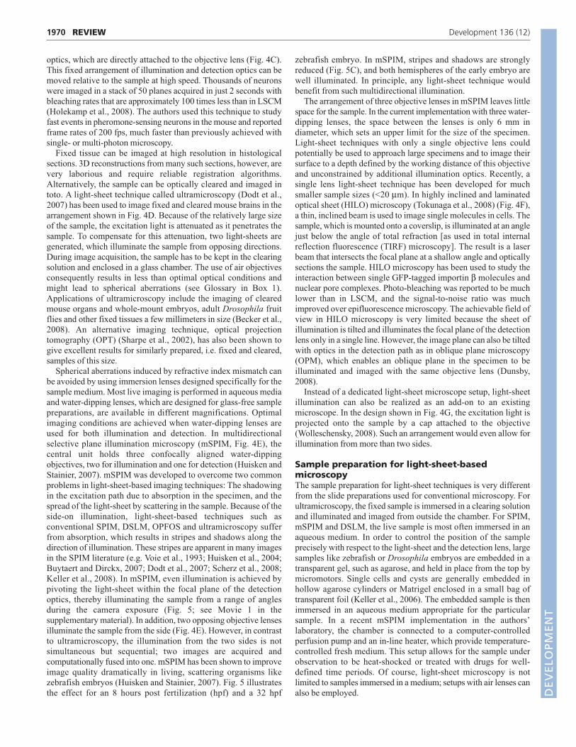
1970
optics, which are directly attached to the objective lens (Fig. 4C).This fixed arrangement of illumination and detection optics can bemoved relative to the sample at high speed. Thousands of neuronswere imaged in a stack of 50 planes acquired in just 2 seconds withbleaching rates that are approximately 100 times less than in LSCM(Holekamp et al., 2008). The authors used this technique to studyfast events in pheromone-sensing neurons in the mouse and reportedframe rates of 200 fps, much faster than previously achieved withsingle- or multi-photon microscopy.
Fixed tissue can be imaged at high resolution in histologicalsections. 3D reconstructions from many such sections, however, arevery laborious and require reliable registration algorithms.Alternatively, the sample can be optically cleared and imaged intoto. A light-sheet technique called ultramicroscopy (Dodt et al.,2007) has been used to image fixed and cleared mouse brains in thearrangement shown in Fig. 4D. Because of the relatively large sizeof the sample, the excitation light is attenuated as it penetrates thesample. To compensate for this attenuation, two light-sheets aregenerated, which illuminate the sample from opposing directions.During image acquisition, the sample has to be kept in the clearingsolution and enclosed in a glass chamber. The use of air objectivesconsequently results in less than optimal optical conditions andmight lead to spherical aberrations (see Glossary in Box 1).Applications of ultramicroscopy include the imaging of clearedmouse organs and whole-mount embryos, adult Drosophila fruitflies and other fixed tissues a few millimeters in size (Becker et al.,2008). An alternative imaging technique, optical projectiontomography (OPT) (Sharpe et al., 2002), has also been shown togive excellent results for similarly prepared, i.e. fixed and cleared,samples of this size.
Spherical aberrations induced by refractive index mismatch canbe avoided by using immersion lenses designed specifically for thesample medium. Most live imaging is performed in aqueous mediaand water-dipping lenses, which are designed for glass-free samplepreparations, are available in different magnifications. Optimalimaging conditions are achieved when water-dipping lenses areused for both illumination and detection. In multidirectionalselective plane illumination microscopy (mSPIM, Fig. 4E), thecentral unit holds three confocally aligned water-dippingobjectives, two for illumination and one for detection (Huisken andStainier, 2007). mSPIM was developed to overcome two commonproblems in light-sheet-based imaging techniques: The shadowingin the excitation path due to absorption in the specimen, and thespread of the light-sheet by scattering in the sample. Because of theside-on illumination, light-sheet-based techniques such asconventional SPIM, DSLM, OPFOS and ultramicroscopy sufferfrom absorption, which results in stripes and shadows along thedirection of illumination. These stripes are apparent in many imagesin the SPIM literature (e.g. Voie et al., 1993; Huisken et al., 2004;Buytaert and Dirckx, 2007; Dodt et al., 2007; Scherz et al., 2008;Keller et al., 2008). In mSPIM, even illumination is achieved bypivoting the light-sheet within the focal plane of the detectionoptics, thereby illuminating the sample from a range of anglesduring the camera exposure (Fig. 5; see Movie 1 in thesupplementary material). In addition, two opposing objective lensesilluminate the sample from the side (Fig. 4E). However, in contrastto ultramicroscopy, the illumination from the two sides is notsimultaneous but sequential; two images are acquired andcomputationally fused into one. mSPIM has been shown to improveimage quality dramatically in living, scattering organisms likezebrafish embryos (Huisken and Stainier, 2007). Fig. 5 illustratesthe effect for an 8 hours post fertilization (hpf) and a 32 hpf
zebrafish embryo. In mSPIM, stripes and shadows are stronglyreduced (Fig. 5C), and both hemispheres of the early embryo arewell illuminated. In principle, any light-sheet technique wouldbenefit from such multidirectional illumination.
The arrangement of three objective lenses in mSPIM leaves littlespace for the sample. In the current implementation with three water-dipping lenses, the space between the lenses is only 6 mm indiameter, which sets an upper limit for the size of the specimen.Light-sheet techniques with only a single objective lens couldpotentially be used to approach large specimens and to image theirsurface to a depth defined by the working distance of this objectiveand unconstrained by additional illumination optics. Recently, asingle lens light-sheet technique has been developed for muchsmaller sample sizes (<20 μm). In highly inclined and laminatedoptical sheet (HILO) microscopy (Tokunaga et al., 2008) (Fig. 4F),a thin, inclined beam is used to image single molecules in cells. Thesample, which is mounted onto a coverslip, is illuminated at an anglejust below the angle of total refraction [as used in total internalreflection fluorescence (TIRF) microscopy]. The result is a laserbeam that intersects the focal plane at a shallow angle and opticallysections the sample. HILO microscopy has been used to study theinteraction between single GFP-tagged importin β molecules andnuclear pore complexes. Photo-bleaching was reported to be muchlower than in LSCM, and the signal-to-noise ratio was muchimproved over epifluorescence microscopy. The achievable field ofview in HILO microscopy is very limited because the sheet ofillumination is tilted and illuminates the focal plane of the detectionlens only in a single line. However, the image plane can also be tiltedwith optics in the detection path as in oblique plane microscopy(OPM), which enables an oblique plane in the specimen to beilluminated and imaged with the same objective lens (Dunsby,2008).
Instead of a dedicated light-sheet microscope setup, light-sheetillumination can also be realized as an add-on to an existingmicroscope. In the design shown in Fig. 4G, the excitation light isprojected onto the sample by a cap attached to the objective(Wolleschensky, 2008). Such an arrangement would even allow forillumination from more than two sides.
Sample preparation for light-sheet-basedmicroscopyThe sample preparation for light-sheet techniques is very differentfrom the slide preparations used for conventional microscopy. Forultramicroscopy, the fixed sample is immersed in a clearing solutionand illuminated and imaged from outside the chamber. For SPIM,mSPIM and DSLM, the live sample is most often immersed in anaqueous medium. In order to control the position of the sampleprecisely with respect to the light-sheet and the detection lens, largesamples like zebrafish or Drosophila embryos are embedded in atransparent gel, such as agarose, and held in place from the top bymicromotors. Single cells and cysts are generally embedded inhollow agarose cylinders or Matrigel enclosed in a small bag oftransparent foil (Keller et al., 2006). The embedded sample is thenimmersed in an aqueous medium appropriate for the particularsample. In a recent mSPIM implementation in the authors’laboratory, the chamber is connected to a computer-controlledperfusion pump and an in-line heater, which provide temperature-controlled fresh medium. This setup allows for the sample underobservation to be heat-shocked or treated with drugs for well-defined time periods. Of course, light-sheet microscopy is notlimited to samples immersed in a medium; setups with air lenses canalso be employed.
REVIEW Development 136 (12)
DEVELO
PMENT

1971REVIEWDevelopment 136 (12)
A common feature of SPIM, mSPIM and DSLM is the abilityto turn the sample. The agarose in which the sample is mountedis therefore usually formed into a cylinder, which provides anunrestricted view from all sides (Fig. 2E). Because of the verticalrotation axis, the sample does not deform when being turned. Formany applications, this additional degree of freedom has turnedout to be essential to orient the sample precisely (e.g. Scherz etal., 2008). The vertical orientation is also an importantprerequisite for multi-view reconstruction, an imaging strategythat, as we discuss below, has attracted extensive research sincethe more widespread adoption of light-sheet-based microscopyapproaches.
Multi-view reconstructionIn multi-view reconstruction (MVR), multiple 3D image stacks areacquired from two or more sides of the same sample. Subsequently,the resulting data stacks are computationally fused into a singledataset. In practice, the acquisition is generally realized by arranginga number of objective lenses around the sample (Swoger et al., 2003)or by imaging the sample at different orientations with a singleobjective lens, as in SPIM (Huisken et al., 2004). There are twomajor benefits to MVR: (1) in large or strongly scattering andabsorbing tissue, the uniformity of image quality is improved(ideally scaling with the number of views); and (2) in transparentsamples and in regions where the datasets overlap, the resolution inimages is improved and becomes isotropic (see Glossary in Box 1;for two orthogonal image stacks, the good lateral resolution of onedataset compensates the poor axial resolution of the other dataset).Generally, a combination of both benefits is achieved in most
samples. MVR in fluorescence light-sheet microscopy is optionaland can be employed when needed. This is in contrast totomographic techniques, in which a certain number of projectionsneed to be acquired before a 3D dataset can be computed. WhereasMVR is not limited to SPIM, it performs especially well in SPIMsetups; owing to their horizontal detection axis, the sample can beturned about a vertical axis with essentially no sample deformation.Also, the high signal-to-noise ratio achieved by SPIM allows the useof further image processing techniques, such as deconvolution,during MVR.
A number of different MVR techniques have been developed. Thegeneral goal of all of these algorithms is to extract the ‘most useful’information from all the datasets and to merge it into a single dataset,replacing the inferior information of other datasets. This idea was firstdeveloped for tilted-view microscopy (Shaw et al., 1989) and laterformulated for a double-axis fluorescence microscope (Kikuchi et al.,1997). Recently, more refined methods have been presented formultiple imaging axis microscopy (MIAM) (Swoger et al., 2003) andSPIM (Swoger et al., 2007). Ultimately, it is desirable to combine thefusion algorithm with a simultaneously performed deconvolutionalgorithm for superior results (Verveer et al., 2007). MVR has beenused for the 3D reconstruction of medaka embryos (Huisken et al.,2004; Swoger et al., 2007), Drosophila embryos (Swoger et al., 2007;Preibisch et al., 2008) and cysts generated with cells of the MDCKkidney cell line (Verveer et al., 2007).
Apart from the combination of multiple views, further imageprocessing and data management tools are useful when using light-sheet microscopy techniques, mainly because of the vast amount ofimage data that can rapidly be recorded. Software packages like
Single-sided + collimatedillumination (here: SPIM)
Double-sided + multidirectionalillumination (mSPIM)
Tg (H2A:GFP)
Tg (H2A:GFP), BODIPY
Out of focus +shaded
Stripes
100 µm80% epiboly, 10×
32 hpf, 40× 25 µm
B C
Aga
rose
Egg water
Embryos
Syringe
Plunger
A
Fig. 5. Comparison of single-sided SPIM and mSPIM. Multidirectional selective plane illumination microscopy (mSPIM) dramatically reducesabsorption and scattering artifacts and provides an evenly illuminated focal plane, as demonstrated with zebrafish embryos. Blue arrows indicatedirection of illumination. (A) Schematic representation of the sample preparation for light-sheet microscopy: multiple zebrafish embryos areembedded in a low melting point agarose cylinder inside a syringe. To image the embryos, the cylinder is partially pushed out of the syringe anddips into the medium-filled chamber (not shown). Three embryos are stacked in the agarose and are sequentially imaged during a time-lapserecording. Shown are early embryos embedded and imaged in their chorion. (B) 8 hpf (top) and 32 hpf (bottom) zebrafish embryos imaged usingSPIM. The illumination from the right in SPIM does not penetrate the whole embryo at 80% epiboly. The light-sheet gets refracted and renders theleft half blurry and patchy. (B, bottom) Stripes are especially apparent at later stages, when pigmentation has occurred, which can block the light-sheet. (C) In mSPIM, by contrast, the sample is sequentially illuminated from two sides from a range of angles. The double-sided illumination yieldsalmost even illumination in the early embryo (C, top), and the pivoting light-sheet eliminates most of the stripes and shadows in the late embryo (C,bottom). See Movie 1 in the supplementary material.
DEVELO
PMENT

1972
ImageJ, Matlab and Labview are widely used for image analysisand data processing on small and large scales. Many publicdomain plugins and scripts can be found for a number of routineimage manipulation tasks (http://rsbweb.nih.gov/ij/plugins/,http://www.mathworks.com/matlabcentral/fileexchange/). Because oftheir high quality (especially good axial resolution, high dynamicrange and low noise), SPIM datasets generally do not require commonpreprocessing routines such as denoising, deconvolution or unmixing.Rather, it is the complexity of the new information from the inside ofliving embryos that calls for new tools for data segmentation,visualization and navigation. As SPIM data are mostly not only 3D,multi-color and multi-view, but also represent a time sequence, it isespecially challenging to extract and illustrate the dynamics that arehidden in these data. A well-executed example of such an analysis isthe recent study of the early embryonic development of the zebrafish,in which 1.5 billion pixels per minute were acquired and automatedimage segmentation and cell tracking were performed on largecomputer clusters to describe hypoblast formation (Keller et al., 2008).Given that such computing power is not available to many researchers,the establishment of collaborations and infrastructures in which thebiology research community has access to microscopy imagedatabases, similar to shared databases from large-scale physicsexperiments, would be beneficial.
Light-sheet-based microscopy’s wide range ofapplicationsBecause of its high depth penetration, low bleaching and highacquisition speed, light-sheet microscopy is ideally suited for anumber of applications. Primarily, in vivo time-lapse studies constitutea growing field where light-sheet microscopy can perform better thanestablished techniques (e.g. confocal microscopy) owing to itssuperior speed and low light exposures. Another benefit of SPIM isthe ability to image whole biological samples under physiologicallyrelevant conditions. In SPIM, the sample is kept alive at optimalconditions, and the microscope has been ‘built around’ the sample inits chamber. By contrast, in classical microscopes, a lot of effort isrequired to include heated chambers and flow cells to keep samplesalive. MVR in SPIM is another unique feature that will enable novel
in toto imaging studies. The ability to image an entire embryo fromdifferent sides is crucial for developmental studies in which cells aretracked over several hours along paths across the entire embryo.However, it has to be taken into account that in light-sheet microscopy,both illumination and detection paths need to be free of obstacles.Hence, more care has to be taken when orienting and embeddingsamples for light-sheet microscopy than for single lens microscopes.Spherical samples, such as early zebrafish embryos, or ellipsoidalsamples, such as Drosophila embryos and larvae, can be imaged wellfrom one or more sides. Large tissues, such as mouse brains, in whichonly a small area on one side is to be imaged, can be difficult to alignto allow proper light-sheet illumination and are therefore not suitablefor MVR.
Light-sheet microscopes can be built and optimized for a widerange of sample sizes, from single cells to whole embryos. Singlecells primarily benefit from the low bleaching; light-sheet basedmicroscopy has helped researchers understand the biophysics ofmicrotubule dynamics and the development of 3D cell cultures(Keller et al., 2006). The study of complex organisms is aided byoptical sectioning and by the ability to use live samples; relativelytransparent embryos like medaka (Huisken et al., 2004) andzebrafish (Keller et al., 2008) are particularly well suited for in vivoimaging in toto. More opaque embryos, such as those of Drosophila,especially benefit from MVR (Swoger et al., 2007). The highacquisition speed of SPIM reduces the recording times significantlywhen millimeter-sized embryos need to be imaged at high resolutionand at short time intervals. Fig. 6 illustrates two examples in whichthe development of the vascular system in zebrafish was monitoredin 3D over time. Image stacks were acquired at time intervals of 5minutes (Fig. 6B; see Movie 2 in the supplementary material) and 1minute (Fig. 6C; see Movie 3 in the supplementary material).
The high sensitivity and speed of SPIM also offers a newapproach to high-speed heart imaging in medaka and zebrafish(Huisken et al., 2004). Heart development has previously beenprimarily analyzed using fixed sections, in which the cardiactissue is often deformed and collapsed. Obviously, the dynamicdevelopment and function of the heart can only be analyzed inliving tissue. Optical sections of beating zebrafish hearts have
REVIEW Development 136 (12)
Tg(flk1:GFP)Tg(gata1:DsRed) 50 µm
8:25 h0:00 h 12:05 h
Aga
rose
Egg water
Fry
Syringe
Plunger
Tg(flk1:ras-mCherry)
A B B��
C�
B�
C�C
Fig. 6. Vascular endothelial cell dynamics at long and short time scales. Dynamics in cell migration are captured with high-speed SPIM time-lapse recordings. (A) Individual or multiple zebrafish larvae are embedded in low melting point agarose. Shown is a single zebrafish larva (Fry) in avertical orientation, which is ideal for imaging the organs in the trunk and the vasculature in the tail. (B-B�) Individual frames from a time-lapsesequence monitoring the sprouting of a vessel (arrow) in the head of a 24 hpf zebrafish. Tg(flk1:GFP)s843 expression labels the endothelial cells andTg(gata1:DsRed)sd2 expression labels the red blood cells. Shown are maximum intensity projections of a 3D stack. (C-C�) Highly dynamic protrusions(arrowheads) in vascular endothelial cells labeled by Tg(flk1:ras-mCherry)s896 expression in a 32 hpf zebrafish. A 3D stack was acquired everyminute. Shown are maximum intensity projections captured 10 minutes apart. See Movies 2 and 3 in the supplementary material. D
EVELO
PMENT

1973REVIEWDevelopment 136 (12)
been collected with commercial confocal laser slit scanningsystems at frame rates of up to 150 frames per second (fps)(Liebling et al., 2006). High-speed cameras can be used in light-sheet microscopy to provide similar frame rates (30-200 fps,depending on the frame size). The full frame acquisition in SPIMis free of motion artifacts and more efficient than the line-by-lineacquisition of slit scanning microscopes. One promisingapplication for SPIM is therefore the 3D-resolved in vivo cardiacoptical mapping during zebrafish heart development. SPIM hasplayed a key role in characterizing the phenotype of a K+ channelgene (kcnh2) mutant by imaging fluctuating Ca2+ concentrationsin the heart with high spatial and temporal resolution (Arnaout etal., 2007). Another transgenic zebrafish line, which expressesGFP in the endocardium and DsRed in the red blood cells, hasbeen used to study valve morphogenesis. By imaging theatrioventricular (AV) canal in these transgenic fish, AV valvemorphogenesis could be investigated at cellular resolution atdifferent developmental stages. SPIM has revealed that what hadbeen previously described as an endocardial cushion actuallyappears to be a dynamic valve leaflet (Scherz et al., 2008). Fig. 7
and Movie 4 (in the supplementary material) show an example ofhigh-speed cardiac imaging. The transgenic zebrafish line usedexpresses DsRed in the blood cells and the myocardium andEGFP in the endocardium.
The distinct sample embedding techniques used for light-sheet-based microscopy might seem taxing at first, but this microscopytechnique also offers a chance to rethink established protocols andto make the transition from fixed to live imaging, or from 2D to 3Dcell and tissue cultures. The embedding medium and the buffer canalso be used to match the refractive index of samples that normallydevelop in air. Fig. 8 (see Movie 5 in the supplementary material)shows an example in which a Drosophila pupa was imagedembedded in agarose. The light-sheet penetrates the pupal case inthe aqueous environment much better than in air and excitesfluorescence in the labeled neurons. A glass capillary is introducedto provide the pupa with air during the time-lapse experiment, whichhad a duration of 10 hours. Sum projections of 3D stacks documentthe process of dendrite pruning (Kuo et al., 2005). At the end of thelarval stage, the mature fly is able to hatch and escape through thecapillary.
At = 0 ms 87 ms 188 ms
V
blood
endoc.myoc. 50 µm
At=0 ms 87 ms 188 ms
V
blood
endoc.myoc.
Tg (flk1:GFP), Tg (cmlc2:DsRed), Tg (gata1:DsRed)
50 µm
Fig. 7. High-speed recordings of zebrafish heart beats. High-speed mSPIM video sequence of a transgenic fish expressing fluorescent proteinsin the endocardium [Tg(flk1:GFP)s843], myocardium [Tg(cmlc2:DsRed)s879] and blood [Tg(gata1:DsRed)sd2]. The movie was recorded at 69 frames persecond. Three frames are shown, corresponding to the atrial diastole (left), the atrial systole (middle) and the ventricular diastole (right). A, atrium;V, ventricle; myoc., myocardium; endoc., endocardium. See Movie 4 in the supplementary material.
Aga
rose
Air
PBS
Pupa
Capillary
Syringe
3:20 h
7:00 h 8:40 h 9:50 h 11:40 h
100 µm
AxonAgarose
Pupa Dendrites
Gasket
A B C
D E F G
Fig. 8. Dendrite pruning in class IV da neurons in Drosophila. Drosophila pupae can be imaged in SPIM over many hours using the depictedembedding. (A) A Drosophila pupa is partially inserted into a glass capillary and embedded in agarose. The high refractive index medium facilitatesimaging structures inside the pupal case, while the glass capillary provides enough air for the pupa to survive and space to hatch. (B) Schematic ofthe abdomen of an early Drosophila pupa, showing the position and the dendritic fields of dorsal class IV da (ddaC) neurons. (C-G) Dendritepruning of one ddaC neuron (outlined in B) during the course of almost 10 hours; shown are timepoints between 3 hours and 20 minutes and 11hours and 40 minutes after pupal formation. Arrowheads point to detaching and degenerating dendrites. Only the axon (arrow) remains in G. SeeMovie 5 in the supplementary material. D
EVELO
PMENT

1974
ConclusionsFluorescence light-sheet microscopy features a number ofadvantages over established microscopy techniques such asepifluorescence microscopy and LSCM. The most prominentbenefit is the reduced photo-toxicity, clearly a feature that every invivo application benefits from. Combined with the rapid acquisitionspeed, it makes light-sheet microscopy the ideal microscopytechnique for extended time-lapse imaging. Fast-moving objects canbe tracked in single-plane movies, and 3D volumes can be rapidlysectioned at high image rates with high sensitivity and anunprecedented dynamic range. Light-sheet microscopy is easilyupgradeable and will therefore directly benefit from the latestcamera technology. Without doubt, cameras with higher resolution,more pixels, better sensitivity and faster data read-out will becomeavailable and will be compatible with, and further enhance, light-sheet microscopy.
SPIM has demonstrated that it is possible to deliver opticalsectioning deep inside extended objects such as millimeter-sizedembryos. The inevitable loss in image quality with increased depthis usually associated with a broadening of the light-sheet and a lossin sectioning. Scattering widens and absorption attenuates the light-sheet as it penetrates dense tissue. The thickness of the light-sheet(and of the optical section) might increase with depth from ~5 μmto 10-15 μm in a millimeter-sized sample. The fluorescenceintensity, however, is almost constant throughout the depth of animage stack. This is in contrast to LSCM, in which the signal issimply lost at a certain depth. In SPIM, the attenuation of the light-sheet along its path can be compensated by multidirectionalillumination, as exemplified by mSPIM. The inherent penetrationdepth of SPIM can be further increased severalfold by acquiringmultiple data stacks and by merging them computationally. Multi-view fusion is currently unique to SPIM and is an indispensible toolfor any object larger than the penetration depth of a single stack. Inaddition, overlapping datasets can be processed to yield an increaseand an isotropy of resolution that is not met by any other single-lensfluorescence microscopy technique. In the future, new algorithmswill become more efficient at handling the enormous amounts ofdata that are acquired in multi-view, multi-color, high-resolution andhigh-speed microscopy. Again, the field will benefit from the latesttechnological developments, with more affordable and morepowerful computers coming to market.
SPIM and other microscopy techniques compatible with wholeorgans and live embryos have opened new dimensions indevelopmental biology; the development of certain organs can befollowed in the living animal at single-cell resolution; the growth ofprimitive cell clusters can be studied in 3D as they form cysts andtubes; and single cells can be tracked as they interact in a matrix freefrom confining glass surfaces. However, the newly gainedexperimental opportunities come at a small but real cost: therequirement to rethink established sample preparation techniquesand to develop new strategies for live imaging. This area is still inits infancy, but new experimental techniques will emerge as morescientists become aware of the importance and usefulness of 3Dsample preparation.
Despite the variety of names and acronyms for light-sheet basedmicroscopes, the multitude of recent developments clearly showshow important light-sheet microscopy techniques are becoming formodern developmental biology. They are a key technology for intoto fluorescence imaging and high-speed image acquisition in liveorganisms. At the same time, the variety of light-sheet-basedmicroscopy implementations shows that the universal concept oflight-sheet illumination can be adapted to a number of different
applications, with samples ranging from single cells to whole mouseembryos. It also demonstrates that there is still room for futuredevelopments. Novel and customized optical elements will becomeavailable in the future to form thinner and more uniform light-sheets,and new objective lenses will provide high NAs at large workingdistances. In summary, the concept of light-sheet-based microscopyis powerful and straightforward, the implementations are manifoldand easily customized to meet individual needs, and the number ofapplications is growing.
We thank Jim Swoger, Stephanie Woo, Kurt Thorn and Geoffrey Lambright forcritical comments on the manuscript; and Sebastian Rumpf and Yuh Nung Janfor providing the Drosophila sample. J.H. is supported by a Human FrontierScience Program (HFSP) fellowship. Support for the SPIM work in our labcomes from grants from the NIH (NHLBI and NIDDK), the Sandler FamilyFoundation and the Packard Foundation to D.Y.R.S. Deposited in PMC forrelease after 12 months.
Supplementary materialSupplementary material for this article is available athttp://dev.biologists.org/cgi/content/full/136/12/1963/DC1
ReferencesArnaout, R., Ferrer, T., Huisken, J., Spitzer, K., Stainier, D. Y. R., Tristani-
Firouzi, M. and Chi, N. C. (2007). Zebrafish model for human long QTsyndrome. Proc. Natl. Acad. Sci. USA 104, 11316-11321.
Becker, K., Jährling, N., Kramer, E. R., Schnorrer, F. and Dodt, H.-U. (2008).Ultramicroscopy: 3D reconstruction of large microscopical specimens. J.Biophotonics 1, 36-42.
Breuninger, T., Greger, K. and Stelzer, E. H. K. (2007). Lateral modulationboosts image quality in single plane illumination fluorescence microscopy. Opt.Lett. 32, 1938-1940.
Buytaert, J. A. N. and Dirckx, J. J. J. (2007). Design and quantitative resolutionmeasurements of an optical virtual sectioning three-dimensional imagingtechnique for biomedical specimens, featuring two-micrometer slicingresolution. J. Biomed. Opt. 12, 014039.
Denk, W. and Horstmann, H. (2004). Serial block-face scanning electronmicroscopy to reconstruct three-dimensional tissue nanostructure. PLoS Biol. 2,e329.
Dodt, H. U., Leischner, U., Schierloh, A., Jährling, N., Mauch, C., Deininger,K., Deussing, J. M., Eder, M., Zieglgänsberger, W. and Becker, K. (2007).Ultramicroscopy: three-dimensional visualization of neuronal networks in thewhole mouse brain. Nat. Methods 4, 331-336.
Dunsby, C. (2008). Optically sectioned imaging by oblique plane microscopy. Opt.Express 16, 20306-20316.
Engelbrecht, C. J. and Stelzer, E. H. K. (2006). Resolution enhancement in alight-sheet-based microscope (SPIM). Opt. Lett. 31, 1477-1479.
Engelbrecht, C. J., Greger, K., Reynaud, E. G., Krzic, U., Colombelli, J. andStelzer, E. H. K. (2007). Three-dimensional laser microsurgery in light-sheetbased microscopy (SPIM). Opt. Express 15, 6420-6430.
Ewald, A. J., McBride, H., Reddington, M., Fraser, S. E. and Kerschmann, R.(2002). Surface imaging microscopy, an automated method for visualizingwhole embryo samples in three dimensions at high resolution. Dev. Dyn. 225,369-375.
Fuchs, E., Jaffe, J. S., Long, R. A. and Azam, F. (2002). Thin laser light sheetmicroscope for microbial oceanography. Opt. Express 10, 145-154.
Haas, P. and Gilmour, D. (2006). Chemokine signaling mediates self-organizingtissue migration in the zebrafish lateral line. Dev. Cell 10, 673-680.
Hell, S. (2007). Far-field optical nanoscopy. Science 316, 1153-1158.Helmchen, F. and Denk, W. (2005). Deep tissue two-photon microscopy. Nat.
Methods 2, 932-940.Holekamp, T. F., Turaga, D. and Holy, T. E. (2008). Fast three-dimensional
fluorescence imaging of activity in neural populations by objective-coupledplanar illumination microscopy. Neuron 57, 661-672.
Huber, D., Keller, M. and Robert, D. (2001). 3D light scanning macrography. J.Microsc. 203, 208-213.
Huisken, J. and Stainier, D. Y. R. (2007). Even fluorescence excitation by multi-directional selective plane illumination microscopy (mSPIM). Opt. Lett. 32, 2608-2610.
Huisken, J., Swoger, J., Del Bene, F., Wittbrodt, J. and Stelzer, E. H. K. (2004).Optical sectioning deep inside live embryos by selective plane illuminationmicroscopy. Science 305, 1007-1009.
Kamei, M. and Weinstein, B. M. (2005). Long-term time-lapse fluorescenceimaging of developing zebrafish. Zebrafish 2, 113-123.
Keller, P. J., Pampaloni, F. and Stelzer, E. H. K. (2006). Life sciences require thethird dimension. Curr. Opin. Cell Biol. 18, 117-124.
Keller, P. J., Schmidt, A. D., Wittbrodt, J. and Stelzer, E. H. K. (2008).
REVIEW Development 136 (12)
DEVELO
PMENT

1975REVIEWDevelopment 136 (12)
Reconstruction of zebrafish early embryonic development by scanned light sheetmicroscopy. Science 322, 1065-1069.
Kikuchi, S., Sonobe, K., Mashiko, S., Hiraoka, Y. and Ohyama, N. (1997).Three-dimensional image reconstruction for biological micro-specimens using adouble-axis fluorescence microscope. Opt. Commun. 138, 21-26.
Kuo, C. T., Jan, L. Y. and Jan, Y. N. (2005). Dendrite-specific remodeling ofDrosophila sensoryneurons requires matrix metalloproteases, ubiquitin-proteasome,and ecdysone signaling. Proc. Natl. Acad. Sci. USA 102, 15230-15235.
Liebling, M., Forouhar, A. S., Wolleschensky, R., Zimmermann, B.,Ankerhold, R., Fraser, S. E., Gharib, M. and Dickinson, M. E. (2006). Rapidthree-dimensional imaging and analysis of the beating embryonic heart revealsfunctional changes during development. Dev. Dyn. 235, 2940-2948.
McLachlan, D., Jr (1968). Microscope. US Patent 3398634.McNally, J. G., Karpova, T., Cooper, J. and Conchello, J. A. (1999). Three-
dimensional imaging by deconvolution microscopy. Methods 19, 373-385.Pawley, J. (2006). Handbook of Confocal Microscopy. New York: Springer.Preibisch, S., Rohlfing, T., Hasak, M. P. and Tomancak, P. (2008). Mosaicing of
single plane illumination microscopy images using groupwise registration andfast content-based image fusion. Proc. SPIE 6914, 69140E.
Rembold, M., Loosli, F., Adams, R. J. and Wittbrodt, J. (2006). Individual cellmigration serves as the driving force for optic vesicle evagination. Science 313,1130-1134.
Ritter, J. G., Veith, R., Siebrasse, J.-P. and Kubitscheck, U. (2008). High-contrast single-particle tracking by selective focal plane illumination microscopy.Opt. Express 16, 7142-7152.
Scherz, P. J., Huisken, J., Sahai-Hernandez, P. and Stainier, D. Y. R. (2008).High-speed imaging of developing heart valves reveals interplay ofmorphogenesis and function. Development 135, 1179-1187.
Sharpe, J., Ahlgren, U., Perry, P., Hill, B., Ross, A., Hecksher-Sørensen, J.,Baldock, R. and Davidson, D. (2002). Optical projection tomography as a toolfor 3D microscopy and gene expression studies. Science 296, 541-545.
Shaw, P. J., Agard, D. A., Hiraoka, Y. and Sedat, J. W. (1989). Tilted viewreconstruction in optical microscopy. Three-dimensional reconstruction ofDrosophila melanogaster embryo nuclei. Biophys. J. 55, 101-110.
Siedentopf, H. and Zsigmondy, R. (1902). Über Sichtbarmachung undGrößenbestimmung ultramikoskopischer Teilchen, mit besonderer Anwendungauf Goldrubingläser. Ann. Phys. 10, 1-39.
Simon, W. (1965). Photomicrography of deep fields. Rev. Sci. Instrum. 36, 1654-1655.
Swoger, J., Huisken, J. and Stelzer, E. H. K. (2003). Multiple imaging axismicroscopy improves resolution for thick-sample applications. Opt. Lett. 28,1654-1656.
Swoger, J., Verveer, P., Greger, K., Huisken, J. and Stelzer, E. H. K. (2007).Multi-view image fusion improves resolution in three-dimensional microscopy.Opt. Express 15, 8029-8042.
Tokunaga, M., Imamoto, N. and Sakata-Sogawa, K. (2008). Highly inclinedthin illumination enables clear single-molecule imaging in cells. Nat. Methods 5,159-161.
Turaga, D. and Holy, T. E. (2008). Miniaturization and defocus correction forobjective-coupled planar illumination microscopy. Opt. Lett. 33, 2302-2304.
Verveer, P. J., Swoger, J., Pampaloni, F., Greger, K., Marcello, M. and Stelzer,E. H. K. (2007). High-resolution three-dimensional imaging of large specimenswith light sheet-based microscopy. Nat. Methods 4, 311-313.
Voie, A. H. (2002). Imaging the intact guinea pig tympanic bulla byorthogonal-plane fluorescence optical sectioning microscopy. Hear. Res. 171,119-128.
Voie, A. H., Burns, D. H. and Spelman, F. A. (1993). Orthogonal-planefluorescence optical sectioning: three-dimensional imaging of macroscopicbiological specimens. J. Microsc. 170, 229-236.
Weninger, W., Geyer, S., Mohun, T., Rasskin-Gutman, D., Matsui, T., Ribeiro,I., Costa Lda, F., Izpisúa-Belmonte, J. C. and Müller, G. B. (2006). High-resolution episcopic microscopy: a rapid technique for high detailed 3D analysisof gene activity in the context of tissue architecture and morphology. Anat.Embryol. 211, 213-221.
Wolleschensky, R. (2008). Arrangement for microscopic observation and/ordetection in a light scanning microscope with line scanning and use. US PatentAppl. US 20080030850.
Zampol, P. (1960). Method of Photography. US Patent 2928734.
DEVELO
PMENT