Selective Laser Sintering 3D Printer
11
Selective Laser Sintering 3D Printer Part 2 ELEC 341 Design Project Muchen He 44638154 Ou Liu 18800152
Transcript of Selective Laser Sintering 3D Printer
Selective Laser Sintering 3D Printer
Part 2
ELEC 341 Design Project
Muchen He 44638154
Ou Liu 18800152

System & Controller Overview
PID(s)=𝐾𝐷𝑠2×
𝐾𝑃𝐾𝐷
𝑠+𝐾𝐼𝐾𝐷
𝑠
𝐾𝑃 = Proportional Gain
𝐾𝐷 = Differential gain
𝐾𝐼 = Integral gain
PID(s) G(s)
H(s)
Desired angle Actual angle+
-
The feedback gain converts the
voltage from sensor back into
angles; which has a net gain of 1 Linearized open loop response

Strategy
1. Obtain open-
loop transfer
function
2. Choose poles
to eliminate3. Root locus 4. Choose K=KD
5. Obtain KP, KI
from KD
6. Fine tune PID
based on
system response
7. Check
stability
To successfully tune our PID to a
minimum value, these are the
steps we took
For the gain K, start with K that
yields a critical damping

Motor Selection
Keeping Q0 at default and changing Q1
We chose AMAX16 p75W SB motor as it
outperforms all other motor and it’s lightweight –
reducing load for the outer motor
Keeping Q1 as AMAX16 p75W SB motor and
changing Q0:
The 6W motor has highest risetime, but performs much
better in other criteria
Ultimately, we chose AMAX22 6W SB motor as it
provided maximum power and torque – good for
heavier loads
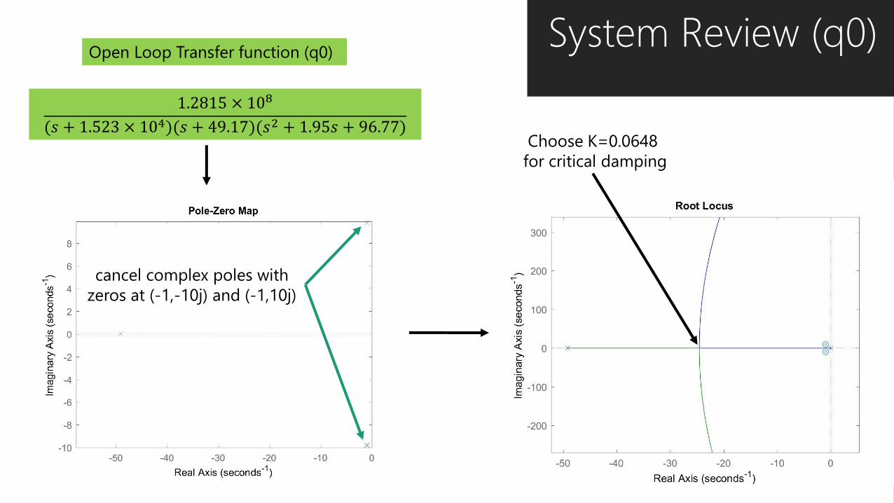
System Review (q0)
1.2815 × 10⁸
(𝑠 + 1.523 × 10⁴)(𝑠 + 49.17)(𝑠2 + 1.95𝑠 + 96.77)
Open Loop Transfer function (q0)
Consider poles close to the origin
cancel complex poles with
zeros at (-1,-10j) and (-1,10j)
Choose K=0.0648
for critical damping

System Review (q1)Open Loop Transfer function (q1)
1.4146 × 10¹⁰
𝑠(𝑠 + 4.045 × 10⁴)(𝑠 + 50.6)(𝑠 + 49.17)
cancel poles closest to
imaginary axis with zeros at
0, -49.17
Choose K=0.0028 for
critical damping

PID Tuning
Rise Time Overshoot Settle Time Steady State
Error
𝐾𝑃 ↓ ↑ ↑ ↓
𝐾𝐼 ↓ ↑ ↑ Eliminate
𝐾𝐷 ↑ ↓ ↓ No effectThe PID for Q0 is adequate from the
starting values, but the risetime is too
long, so we increased D-gain and I-gain.
This caused more overshoot so we
decreased P gain PID values Q0 Q1
P-gain I-gain D-gain P-gain I-gain D-gain
Starting 0.1464 6.2707 0.0648 0.1377 0.00 0.0028
Intermediate 0.123 8.470 0.0940 0.1360 0.03 0.0029
Final 0.070 9.650 0.100 0.1366 0.00 0.0028

Step response of Q0 with PID Step response of Q1 with PID
Progression of PID Tuning Risetime and settling time for Q0
improved drastically after fine tuning.
Overshoot is decreased as wellMotor Q1 had a good starting
point as it is easier to control.
Fine tuning reduced overshoot

Simulation Results
Simulation is ran with PID
tuned at different stages: start,
intermediate, and final. The
maximum position error is
reduced drastically
Desired position
Final
Max. position error: 3.29
Intermediate
Max. position error: 6.98
Starting
Max. position error: 45.2

Nyquist Stability Criteria
Motor Q1 controller
Motor Q0 controller
Q0
Gain margin: 59.2 dB
Phase margin: 52 degrees
The Nyquist stability criterion plot is used to
determine how close our system with PID is to
unstable
The system with finalized PID values is stable
as seen in the Nyquist plot
Q1
Gain margin: 15.4 dB
Phase margin: 4.1 degrees

Result of PID Auto Tuner Less control over steady state error
Greater instabilityStep response of Q0 with PID tuner
Step response of Q1 with PID tuner
Actual position
Position error
Tuning by hand is the
better method
Max. position error: 58.18
Q0 auto tune PID
Q1 auto tune PID


![Optimizing selective laser sintering process by grey ...doras.dcu.ie/22813/1/main2.pdf · The selective laser sintering (SLS) was invented in 1989 [1]. In this process, laser employed](https://static.fdocuments.net/doc/165x107/601e4d4954f29749226768bf/optimizing-selective-laser-sintering-process-by-grey-dorasdcuie228131main2pdf.jpg)