SELECTION OF TUNNEL METHODS - Mines
64
SELECTION OF TUNNEL METHODS By: Dr. Gary S. Brierley
Transcript of SELECTION OF TUNNEL METHODS - Mines

SELECTION OF TUNNEL METHODS By: Dr. Gary S. Brierley

Successful Tunnel “Design” 2
Produce a satisfactory finished facility
for no more money and in no more
time than is required for the
existing ground conditions.

Tunnels are Different than Above-Ground Structures
3
Entirely within the ground.
The ground cannot be specified.
The ground can be changed.
Serial Construction Schedule.

Tunnels are Different than Above-Ground Structures
4
Work from inside/out.
The ground requires temporary support.
Lots of third party impacts.
Land not owned by project.

Building a Tunnel 5
Excavate the ground
Control the ground during the process of excavation.
Support the ground as the tunnel is advanced.
Install the final lining.
Evaluating Tunneling Issues 6

Risk Management 7
The Geotech The Designer The Contractor The Owner Third Parties Insurers, etc.

Case Histories 8

Phoenix Casa Grande Highway


Lake Merced


Coldwater Sanitary Relief Project 23

BRIERLEY ASSOCIATES
Coldwater Creek and
Existing Trunk Sewer
Alignment
Lambert St. Louis
International Airport
Coldwater WWTP
Drainage Pattern
24

TH-14
TH-11 TH-13
TH-10 TH-12
TH-9 TH-7
TH-8
TH-5
TH-6 TH-3
TH-1
TH-4 TH-2
TH-15 Geotechnical Investigation
Tunnel Alignments
Public ROW Roadways
Creek / Easement Parallel Existing Trunk Sewer
Test Hole Locations 15 Total Test Holes
• Spatial Variation • Representative Mix • Based on Alignments
25

BRIERLEY ASSOCIATES PROFILE ALONG CREEK
AIRPORT
WWTP
TH-1
TH-3 TH-5
TH-7 TH-9 TH-10 TH-11 TH-14
26


South Austin Regional Wastewater Treatment Plant
Presented By:
Kevin Koeller, P.E.
Gary Brierley, P.E.
Tunneling Through Backfill and Lift Station Walls Without Disturbing Plant Operations
28

Project Background SARWWTP receives
flow from the south half of Austin (SAR Service Area)
PER confirmed flow from service area
Flow from two separate service areas is delivered to the site via two tunnels
Tunnels terminate in two separate lift stations approximately 90 feet deep
No definition of division of flow
29
Existing Govalle Tunnel
Existing Onion Creek
Tunnel

Tunnel Route
Avoid Damage to Operating Facilities
Minimize Interruptions of Plant Operations
Tunnel Must be Constructible
30
Lift Station No. 1
Lift Station No. 2
Interconnect Tunnel
Access Shaft Access Shaft
Drain Tunnel No 4

Tunnels Between Access Shafts No. 2
Access Shaft 1 to Access Shaft 2 – 768 ft
Decker Model 70 TBM – 5.75 ft dia
Hobas Pipe – 63 in. Downhill - 0.2% Taylor Shale
31

Backfill of Existing Lift Stations 32
Probing Operations Compaction Grouting

Saguaro Ranch Tunnel

Portal Cut 34

Horizontal Boring 35

Pilot Tunnel 36
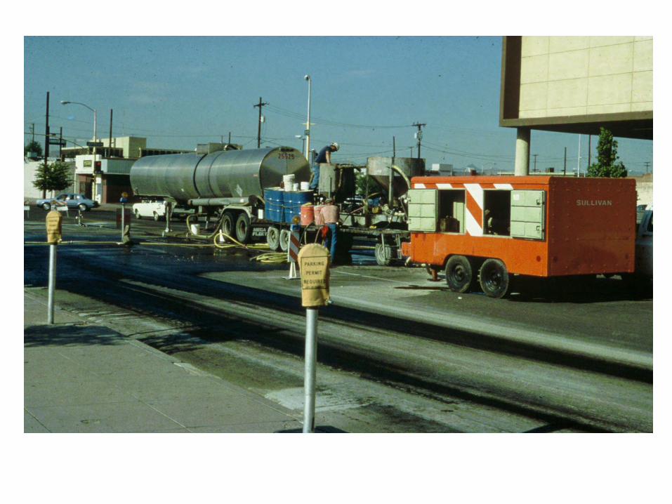
Shotcrete 37

Top Heading 38

Final Tunnel 39

Grand & Bates Sewer Relief Tunnel 40

Tunnel Alignment 41
Grand & Bates / Plan View

Subsurface Conditions 42
Overburden Soil 25 to 75 ft. fill/loess/alluvial soils Rubble fill (rip rap) at Outfall Structure
Highly Weathered Limestone Low quality fractured zones with shale seams Pinnacled surface/karst potential k = 2.5 x 10⁻³ cm/sec
Unweathered St. Louis Limestone White-light Gray, thin-massive bedding Chert lenses and nodules k = 1.5 x 10⁻⁵ cm/sec

VE Proposed Alternative Alignment 43
Simplified Alignment Reduces Construction Time, Effort, and Cost

Increased Tunnel Diameter 44
132-in Precast Concrete Liner Pipe increases storage volume by over 40%

Limited Use of Drill & Blast 45
Drill-Blast Starter Tunnel Used to Permit Assembly of TBM

Simplified Ground Support 46
5.5 ft. #8 Resin Grouted Rock dowels and WWF Provide Primary Crown Support
8 x 11.5 in. Channel Crown Sets at Railroad & Highway Crossings

Montreal 47


New Crystal Springs Bypass (Polhemus) Tunnel
Design Challenges
By:
Dr. Gary S. Brierley
City And County Of San Francisco Public Utilities Commission
San Francisco Water Department
53
June 27, 2007

SFPUC Water Supply Improvement Program
54

Need for the Project 55


Project Location 57
South Shaft Area
North Shaft Landslide area
New Tunnel

Ground Conditions 58

Ground Conditions 59
Mélange Matrix
Sandstone

Tunnel Boring Machine

Temporary Tunnel Lining 61


Crossing San Mateo Creek 63

A Final Recommendation: THINK! THINK! THINK!