Selection of Cost Effective Plasma Cutting Process for ...
34
Shortened Version Selection of Cost Effective Selection of Cost Effective Plasma Cutting Process for Weld Plasma Cutting Process for Weld Integrity Integrity Nakhleh Hussary, PhD, Thierry Renault, PhD Thermadyne Inc. Geoffrey H. Putnam G.H. Putnam Consulting
Transcript of Selection of Cost Effective Plasma Cutting Process for ...

Shortened Version
Selection of Cost Effective Selection of Cost Effective Plasma Cutting Process for Weld Plasma Cutting Process for Weld
IntegrityIntegrityNakhleh Hussary, PhD, Thierry Renault, PhD
Thermadyne Inc.
Geoffrey H. Putnam G.H. Putnam Consulting

Shortened Version
OutlineOutline• Goal, Scope & Motivation• Background• Experimental Setup• Results & Discussion• Summary & Conclusion

Shortened Version
GoalGoal• Effect of plasma cutting method on Stainless Steel and
Aluminum weldability.
– Intent: maximize the effect of surface contaminants caused by the cutting methods used on the subsequent autogenous weld properties.
• Selection of cost effective cutting process for welding applications.

Shortened Version
ScopeScope• Limit the study to:
– Stainless Steel: 304• Wide availability and use
– Aluminum: 5052 H32• Weldable with GTAW in autogenous mode• Wide availability and use
– Thickness: ¼” (5 – 6mm)• Near upper limit for autogenous mode• Weld repeatability
• Limit the cutting process to high quality cutting– Ar/H2 (H35: 35%H2 by volume) plasma and N2 secondary– N2 plasma and H2O secondary
• Limit joining to an autogenous weld• Gas/fluid quality:
– Industrial grade N2– Welding grade Ar-H2– Tap water – untreated – (Lebanon, NH)

Shortened Version
OutlineOutline• Goal, Scope & Motivation• Background• Experimental Setup• Results & Discussion• Summary & Conclusion

Shortened Version
Alternative ProcessesAlternative ProcessesSheet Product CuttingSheet Product Cutting
Plasma
Water
Oxyfuel
Laser
Slow SpeedMedium-High Capital CostHigh Operating Cost
Slow SpeedLow Capital CostHigh Operating Cost
High SpeedMedium Capital CostLow Operating Cost
High QualityHigh PrecisionHigh Reproducibility
High QualityHigh PrecisionMedium-High Reproducibility
Low QualityLow PrecisionHigh Reproducibility
Medium QualityMedium PrecisionLow Reproducibility
High SpeedHigh Capital CostMedium to high Operating Cost
Gauge – 2”+1mm - 50mm
1.5”+30mm +
1/4” - 2”5mm – 50mm
Gauge - 1/2”1mm – 12mm
Arrow indicate thicker materialColor intensity indicate optimum thickness range

Shortened Version
Metal Cutting MethodsMetal Cutting MethodsComparisonComparison
Speeds (m/min)
(ipm)
ThicknessSS
Water Jet
Pump
(27kW)
Laser
CO2 laser
(4 kW)
Plasma
N2/H2O
(14-16 kW)
6mm~ ¼”
0.32~13
2.1~83
2.7~106
12mm~1/2”
0.13~5
0.75~20
1.4~55

Shortened Version
Plasma CuttingPlasma CuttingH35 vs. NH35 vs. N22/H/H22OO
H35 N2/H2O
QualityHigh Precision:
No DrossSharp Edges
Cut Angle < 2 Degrees
High Precision:No Dross
Sharp EdgesCut Angle < 2 Degrees
Speed100A / ¼” Thickness
SS: 72 ipm (1.83 m/min)Al: 80 ipm (2.03 m/min)
100A / ¼” ThicknessSS: 95 ipm (2.41 m/min)Al: 90 ipm (2.29 m/min)
Current Range
Thickness Range
100A – 300A +
¼” +
30A – 300A +
Gauge +
Shortened Version
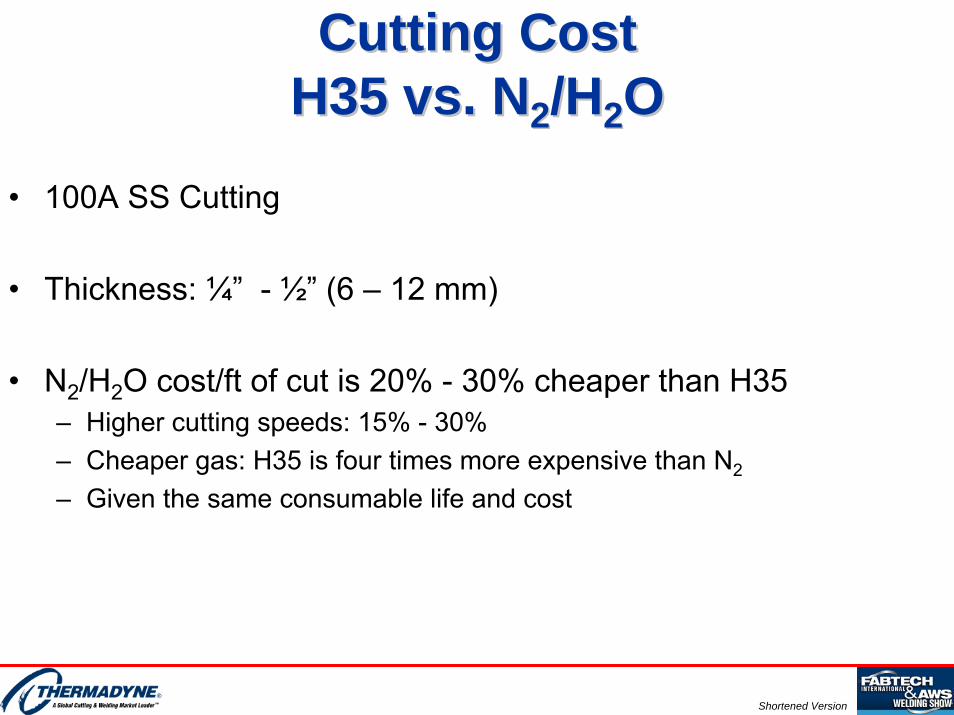
Cutting Cost Cutting Cost H35 vs. NH35 vs. N22/H/H22OO
• 100A SS Cutting
• Thickness: ¼” - ½” (6 – 12 mm)
• N2/H2O cost/ft of cut is 20% - 30% cheaper than H35 – Higher cutting speeds: 15% - 30%– Cheaper gas: H35 is four times more expensive than N2
– Given the same consumable life and cost
Shortened Version
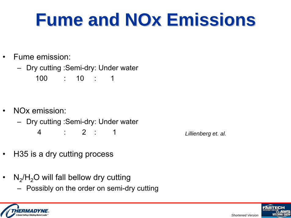
Fume and Fume and NOxNOx EmissionsEmissions
• Fume emission:– Dry cutting :Semi-dry: Under water
100 : 10 : 1
• NOx emission:– Dry cutting :Semi-dry: Under water
4 : 2 : 1
• H35 is a dry cutting process
• N2/H2O will fall bellow dry cutting – Possibly on the order on semi-dry cutting
Lillienberg et. al.

Shortened Version
Literature OverviewLiterature Overview• Concentration of literature dealing with weldability of plasma air cutting on carbon
steel [Frolov, Williamson, Kobeleva et. al., Vasil’ev et. al., Fujimura, et. al., Haferkamp et. al.]
– Particularly before oxygen cutting became economically viable.
• Metallurgical effects of plasma cutting of carbon steel, stainless steel and aluminum as well as effect on weldability [O’Brien et. al., Levin et. al., Bach et. al., Skillingberg, Masiashvili et. al., Hackett, Uchida et. al.]
– Size of heat affected zone (perpendicular & parallel to cut face)• Due to thickness• Current level• Plasma gas composition• Material type, alloying and tempering
– Micro-hardness
• Comparison with oxy-fuel cutting.
• Little available in terms of comparing weldability of SS /Al using H35 and N2/H2O– Significant improvements on cutting systems since inception.
Shortened Version
OutlineOutline• Goal, Scope & Motivation• Background• Experimental Setup• Results & Discussion• Summary & Conclusion

Shortened Version
Experimental SetupExperimental SetupPlasma CuttingPlasma Cutting
• Plasma Cutting Process– Mechanized dual gas system– Water cooled torch
100A
S.S.Al
Plasma
Flow[SLPM (SCFH)]
Pressure[Bar (psig)]
Shield
Flow[SLPM (SCFH)]
Pressure[Bar (psig)]
Speed
[m/min (IPM)]
Standoff
[mm (in)]
Voltage
[V]
H35/N2
Flow20.1(42.6)
Pressure6.2 (90)
Flow39(82.6)
Pressure 8.3 (120)
1.83 (72)2.03 (80)
2.54 (0.100)5.08 (0.200)
158160
N2/H2O
Flow12.5 (26.5)
Pressure6.2 (90)
[SLPM / GPH]0.44 / 7
Pressure3.8 (55)
2.41 (95)2.29 (90)
2.54 (0.100)3.81 (0.150)
148160
Shortened Version
Cut Surface Elemental Analysis: Cut Surface Elemental Analysis: Scanning Auger MicroanalysisScanning Auger Microanalysis
• Goal: measure the content of atomic nitrogen in the cut face on Al and SS cut with N2/H2O and H35/N2.
• Surface analysis technique that determines elemental composition and some chemistry of surfaces and interfaces.
• Sampling depth of 2-3nm with lateral resolution of 50 nm.
• SAM also shows the spatial distribution of elements on a surface (SAM element images) as well as elemental depth distributions from 1 to 2000 nm (when used in conjunction with ion-milling).
• Detection limit: all atomic elements (except hydrogen and helium) at concentrations greater than 0.1 atomic percent.

Shortened Version
Cut Surface Elemental Analysis: Cut Surface Elemental Analysis: Scanning Auger MicroanalysisScanning Auger Microanalysis
• Principle Of Operation:– Sample scanned with focused electron beam
• Auger electrons (low energy) emission.– Auger electron energies measured
• Elemental surface analysis (top few monolayers).– Argon ion beam can be used to remove surface layers from the sample.
Incident Beam
e-Sputter Etching
Ar+
1min ~ 20nm
Electron Energy
Analyzer
Auger
e-
Sample
Shortened Version
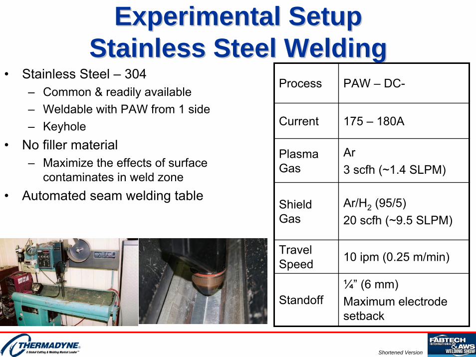
Experimental SetupExperimental SetupStainless Steel WeldingStainless Steel Welding
• Stainless Steel – 304– Common & readily available– Weldable with PAW from 1 side– Keyhole
• No filler material– Maximize the effects of surface
contaminates in weld zone• Automated seam welding table
Process PAW – DC-
Current 175 – 180A
Plasma Gas
Ar3 scfh (~1.4 SLPM)
Travel Speed 10 ipm (0.25 m/min)
Standoff¼” (6 mm)Maximum electrode setback
Shield Gas
Ar/H2 (95/5)20 scfh (~9.5 SLPM)

Shortened Version
Experimental SetupExperimental SetupAluminum WeldingAluminum Welding
• Aluminum: 5052 - H32– Common & readily available– Weldable with GTAW– Two sided weld
• No filler material– Maximize the effects of surface
contaminates in weld zone
• Automated seam welding table
Process GTAW – AC pulse
Current350A, 250A back side50% background current, 40 pps
Shield Gas
75% He / 25% Ar20 scfh (~9.5 SLPM)
Travel Speed 11 ipm (0.28 m/min)
Standoff 1/8” (~3 mm)

Shortened Version
Experimental SetupExperimental SetupTensile PullTensile Pull
• Following Standard:– AWS B4.0M: Standard Methods for
Mechanical Testing of Welds– AWS D1.6: Structural Welding Code -
Stainless Steel– AWS D1.2: Structural Welding Code -
Aluminum• Instrument
– Tensile testing unite: Sawyer Mfg. Company, Model 273-25
• Number of Samples:– SS & Al
• 12 H35/N2• 12 N2/H2O• 2 sheared surface weld
AWS B4.0M
AWS B4.0M

Shortened Version
Experimental SetupExperimental SetupBend TestBend Test
• Following Standard:– AWS B4.0 Standard methods for
mechanical testing of welds– AWS D1.6 Structural welding code
stainless steel– AWS D1.2 Structural welding code
aluminum• Mandrel 1/2” radius for 1/4 “ thick
samples with 20% elongation • Three top bends & three bottom
bends for:• H35/N2 and N2/H2O• Al & SS
– Sheared surface weld: 1 top bend and 1 bottom bend.

Shortened Version
Experimental SetupExperimental SetupMaterial CharacterizationMaterial Characterization
• Micrographs of as cut material and welded material– Sectioning and mounting in epoxy– Polishing (metallographic finish)– micrograph imaging
• Knoop microhardness test (100g for Al, 300g for SS)– As cut samples– Base metal, heat affected zone (HAZ) and weld– Knoop hardness number (KHN):
KHN = F/A = P/CL2 F = applied load (kgf)
A = un-recovered projected area in mm2
– Precision of measurements: 1 hardness unit.
Work Performed by New Hampshire Materials Laboratory, Somersworth, NH

Shortened Version
OutlineOutline• Goal, Scope & Motivation• Background• Experimental Setup• Results & Discussion• Summary & Conclusion
Shortened Version
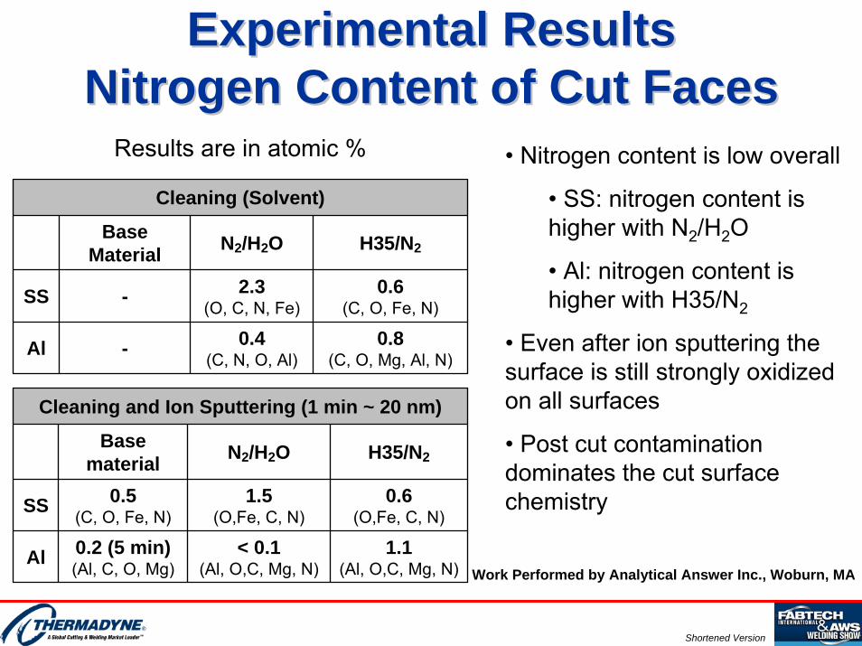
Experimental ResultsExperimental ResultsNitrogen Content of Cut Faces Nitrogen Content of Cut Faces
Cleaning (Solvent)
BaseMaterial N2/H2O H35/N2
SS - 2.3(O, C, N, Fe)
0.6(C, O, Fe, N)
Al - 0.4(C, N, O, Al)
0.8(C, O, Mg, Al, N)
1.1(Al, O,C, Mg, N)
< 0.1(Al, O,C, Mg, N)
0.2 (5 min)(Al, C, O, Mg)Al
0.6(O,Fe, C, N)
1.5(O,Fe, C, N)
0.5(C, O, Fe, N)SS
H35/N2N2/H2OBase
material
Cleaning and Ion Sputtering (1 min ~ 20 nm)
• Nitrogen content is low overall
• SS: nitrogen content is higher with N2/H2O
• Al: nitrogen content is higher with H35/N2
• Even after ion sputtering the surface is still strongly oxidized on all surfaces
• Post cut contamination dominates the cut surface chemistry
Results are in atomic %
Work Performed by Analytical Answer Inc., Woburn, MA

Shortened Version
Experimental ResultsExperimental ResultsEffect of Cut Gases on Cut Surface Effect of Cut Gases on Cut Surface
• Al– H35 shows larger recast layer– Comparable HAZ
• SS– H35 shows largerrecast layer and HAZ
• Layer thickness is less than 0.010”(0.25mm) on all cut surfaces
0
0.001
0.002
0.003
0.004
0.005
0.006
0.007
Al N2/H2O
AlH35/N2
SSN2/H2O
SSH35/N2
Thic
knes
s [in
] Recast LayerHAZ

Shortened Version
Experimental ResultsExperimental ResultsAs Cut Samples As Cut Samples –– Al/SS MicrographsAl/SS Micrographs
N2/H2O H35
Al
SS
Shortened Version
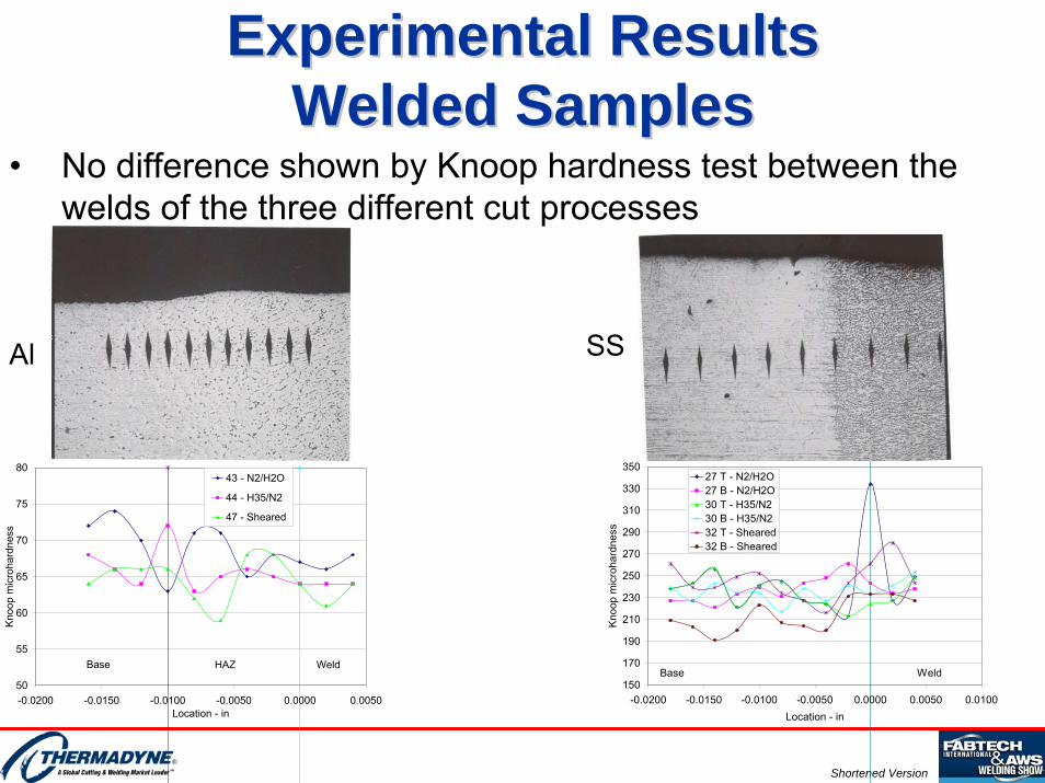
Experimental ResultsExperimental ResultsWelded SamplesWelded Samples
• No difference shown by Knoop hardness test between the welds of the three different cut processes
50
55
60
65
70
75
80
-0.0200 -0.0150 -0.0100 -0.0050 0.0000 0.0050Location - in
Kno
op m
icro
hard
ness
43 - N2/H2O
44 - H35/N2
47 - Sheared
Base HAZ Weld
Al SS
150
170
190
210
230
250
270
290
310
330
350
-0.0200 -0.0150 -0.0100 -0.0050 0.0000 0.0050 0.0100Location - in
Kno
op m
icro
hard
ness
27 T - N2/H2O27 B - N2/H2O30 T - H35/N230 B - H35/N232 T - Sheared32 B - Sheared
WeldBase

Shortened Version
Results: Tensile Strength AlResults: Tensile Strength Al• Statistically indistinguishable
tensile strengths between H35/N2 and N2/H2O
• Tensile results are higher than minimum specified– Aluminum Association: 25ksi
0
5
10
15
20
25
30
35
40
N2/H2O Ar-H2/N2 Shear Base
Tens
ile S
treng
th [k
si]
Precision Limit
20
25
30
35
40
40 45 50 55 60Sample #
Tens
ile S
treng
th [k
PS
I]
20
25
30
35
4040 45 50 55 60
Al H35/N2 - 1Sheared - 1Al H35/N2 - 2Al N2/H2O - 2Al Sheared - 2Base Metal - 1Al N2/H2O - 1
Aluminium Association: standard Minimum for Al 5052 25ksi

Shortened Version
Results: Tensile Strength SSResults: Tensile Strength SS• Statistically indistinguishable
tensile strengths between H35/N2 and N2/H2O.
• Slightly higher values of base material
• Tensile results are higher than minimum specified – AWS D1.6: 75ksi.
70
75
80
85
90
95
100
105
110
20 25 30 35 40Sample #
Tens
ile S
treng
th [k
PS
I]
70
75
80
85
90
95
100
105
11020 25 30 35
SS H35/N2ShearedBase MetalSS N2/H2O
AWS D1.6 standard Minimum for SS 304 75kPSI
0
10
20
30
40
50
60
70
80
90
100
110
120
N2/H2O H35 Shear Base
Tens
ile S
treng
th [k
si]

Shortened Version
Experimental Results Experimental Results Bend Tests: SSBend Tests: SS
• Acceptance Criteria: AWS D1.6 & D1.2– Measured all observable discontinuities on convex surface
• 1mm (1/32”) and above– Classified measurements for failure criteria
• Fail if corner crack • Fail if any discontinuity ≥ 3mm (1/8”)• Fail if sum of discontinuities under 3mm ≥ 10mm (3/8”)
• Stainless Steel– No corner cracks – No discontinuities observed
• No observable effect of cutting process on bend test

Shortened Version
Experimental Results Experimental Results Bend Tests: Al Bend Tests: Al
• Aluminum– No corner cracks– Failure of one sample from
one side• N2/H2O welded cut
• Appearance of discontinuities not exclusive to a particular cut process
• No correlation between top bend / bottom bend and appearance of discontinuities
• Note: – No cleaning was performed
prior to welding on any cut surface
0
1
2
3
4
5
6
41-T
41-B
42-T
42-B
43-T
43-B
44-T
44-B
45-T
45-B
46-T
46-B
47-T
47-BSample #
Dis
cont
inui
ty C
ount
(>1m
m) Red - H35
Blue - N2/H2OGreen - Shear
Failed
Shortened Version
OutlineOutline• Goal, Scope & Motivation• Background• Experimental Setup• Results & Discussion• Summary & Conclusion
Shortened Version
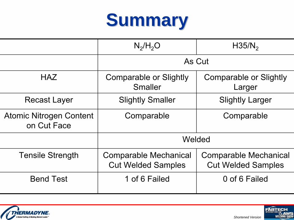
SummarySummaryN2/H2O H35/N2
As Cut
HAZ Comparable or Slightly Smaller
Comparable or Slightly Larger
Recast Layer Slightly Smaller Slightly Larger
Atomic Nitrogen Content on Cut Face
Comparable Comparable
Welded
Tensile Strength Comparable Mechanical Cut Welded Samples
Comparable Mechanical Cut Welded Samples
Bend Test 1 of 6 Failed 0 of 6 Failed

Shortened Version
ConclusionConclusion• Weld integrity is maintained regardless of cutting process:
sheared, N2/H2O plasma cut, H35/N2 plasma cut.• No added alloying element in the weld to compensate for the loss of alloys in
the base metal due to the welding operation
• Pre weld preparation should be required on any cut surface per welding standards
• N2/H2O cutting process is recommended:– No compromise on weldability– High definition cut quality– Larger thickness range and parameter windows– Lower fume and NOx emissions– Lower cost

Shortened Version
Limitations and Future StudyLimitations and Future Study• Material thickness for as cut characterization and welding study
– May require use of filler material
• Surface contamination due to environment
• Other cutting gas mixtures– Air/Air– N2/N2– N2-H2/N2– Other
• N2/H2O & H35/N2 Fume and NOx generation as a function of thickness and current

Shortened Version
ReferencesReferences• Frolov, V.A., The mechanism of the nitrogen saturation of the edges of work pieces cut by air plasma cutting, Welding
Production, v24, n124, pp. 59-61, 1977.• Williamson, B., Effect of plasma cutting with oxygen/nitrogen mixtures on the formation of defects when MAG welding carbon
steels, Welding in the World, v27, n9/10, pp. 282-289, 1989.• Kobeleva, N.K., A.P. Drozdov, V.M. Zhikol, Prevention of pore formation in the welding of components of hull steels by plasma
cutting in air, Welding Production, v22, n3, pp. 45-48, 1975.• Lillienberg, L. and B. von Bromssen, Emissions of fumes and nitrogen oxides from plasma cutting of stainless steel, Welding in
the World, V37, n6, pp. 308-315, 1996.• Vasil’ev, K.V. and L.O. Kokhlikyan, Weld Porosity in welding on edges prepared by air-plasma cutting and its prevention, Svar.
Proiz., n4, pp. 47-49, 1976.• Fujimura, H. and T. Kawano, Studies on blowhole formation in welding of air-plasma cut steel plates, Translation of the Japan
Welding Society, v18, n1, pp. 46-53, 1987. • Haferkamp H., F.W. Back, A. Gruchow, Geometrical/metallurgical properties and the applicability of underwater flame cutting
and plasma arc cutting edges for wet weld preparation, Proceedings of the 11th International Conference on Offshore Mechanics and Arctic Engineering, Calgary, pp. 127-133, 1992.
• O’Brien, R.L., R.J. Wickham, W.P. Keane, Advances in Plasma Arc Cutting, Welding Journal, v43, n12, pp. 1015-1021, 1964.• Levin, M.L., Plasma cutting and gouging, British Welding Journal, May, pp. 213-221, 1964.• Bach, W., A. Gruchow, Plasma cutting in atmosphere and under water, Pure & Appl. Chem., v64, n5, pp. 665-670, 1992.• Skillingberg, M.H., Plasma arc cutting of aluminum – metallurgical effects, Proceedings of the Aluminum Joining Seminar, pp.
315-328, 1986.• Masiashvili, O.Ya., R.N. Suladze and Sh.I. Begiashvili, Condition of the heat affected zone in plasma cut metals, Welding
Production, v17, n7, pp. 53-57, 1970.• Hackett, M.H., Plasma cutting stainless steel and aluminum – investigating thermal and chemical changes in the heat-affected
zone, The Fabricator, July, 2001.• Uchida, A., K. Oishibashi and K. Hagiwara, Plasma arc cutting of aluminum alloys for rolling stock construction – properties of
cut-surface and influence of plasma arc cutting on the weld, Quarterly Reports, Railway Technical Research Institute, v10, 3, pp. 163-169, 1969.