Selection of Cameras, Digital Recording Systems, Digital High ...
51
APTA STANDARDS DEVELOPMENT PROGRAM RECOMMENDED PRACTICE American Public Transportation Association 1666 K Street, NW, Washington, DC, 20006-1215 APTA IT-CCTV-RP-001-11 Published June 2011 CCTV Standards Working Group This Recommended Practice represents a common viewpoint of those parties concerned with its provisions, namely, transit operating/planning agencies, manufacturers, consultants, engineers and general interest groups. The application of any standards, practices or guidelines contained herein is voluntary. In some cases, federal and/or state regulations govern portions of a transit system’s operations. In those cases, the government regulations take precedence over this standard. APTA recognizes that for certain applications, the standards or practices, as implemented by individual transit agencies, may be either more or less restrictive than those given in this document. © 2011 American Public Transportation Association. No part of this publication may be reproduced in any form, in an electronic retrieval system or otherwise, without the prior written permission of the American Public Transportation Association. Selection of Cameras, Digital Recording Systems, Digital High-Speed Networks and Trainlines for Use in Transit-Related CCTV Systems Abstract: This Recommended Practice provides guidelines for the selection of cameras, digital recording equipment and digital high-speed trainlines for use in transit-related CCTV applications. Keywords: 100 base-T, analog camera, CCTV, codec, coupler, digital camera, digital video recorder (DVR), Ethernet, field of view (FOV), hard drive, LAN, memory, MPEG, network, pan tilt zoom (PTZ), safety, security, specification, trainline, videocassette recorder (VCR), VHS, video camera, WAN, webcam Summary: This document provides guidelines for the use of cameras in CCTV security systems in transit- related applications, such as rail cars, buses, depots and stations. It discusses both attended and unattended cameras, which include stationary cameras as well as PTZ cameras. On-site recording devices such as VCRs, DVRs and hard disks also will be discussed, as will data highway, backbone and structured wiring and trainline network requirements. Data network requirements for rail vehicles will be discussed in a separate section (Section 5) specifically focused on high-speed digital trainlines. Scope and purpose: This document will apply equally to camera systems in fixed installations, such as stations and depots, as well as mobile camera systems on trains, buses, etc. It does not cover recommendations or requirements to site cameras in specific locations, a topic covered by a separate Recommended Practice. This document applies to any camera used within a transit-related CCTV system so that it, and its associated recording system and network connections, will be technically appropriate for the uses they are required to perform. This document allows operators, security agencies and other agencies a consistent recommended practice across the industry. This Recommended Practice will ensure that the quality of imagery obtained from direct camera feeds, recordings and network systems used within transit-related CCTV systems are of a consistent and acceptable level, as set out in this document. This will enable the CCTV systems to be used effectively for the purpose they were intended.
Transcript of Selection of Cameras, Digital Recording Systems, Digital High ...

A P T A S T A N D A R D S D E V E L O P M E N T P R O G R A M
RECOMMENDED PRACTICE American Public Transportation Association
1666 K Street, NW, Washington, DC, 20006-1215
APTA IT-CCTV-RP-001-11 Published June 2011 CCTV Standards Working Group
This Recommended Practice represents a common viewpoint of those parties concerned with its provisions, namely, transit operating/planning agencies, manufacturers, consultants, engineers and general interest groups. The application of any standards, practices or guidelines contained herein is voluntary. In some cases, federal and/or state regulations govern portions of a transit system’s operations. In those cases, the government regulations take precedence over this standard. APTA recognizes that for certain applications, the standards or practices, as implemented by individual transit agencies, may be either more or less restrictive than those given in this document.
© 2011 American Public Transportation Association. No part of this publication may be reproduced in any form, in an electronic retrieval system or otherwise, without the prior written permission of the American Public Transportation Association.
Selection of Cameras, Digital Recording Systems, Digital High-Speed Networks and Trainlines for Use in Transit-Related CCTV Systems
Abstract: This Recommended Practice provides guidelines for the selection of cameras, digital recording equipment and digital high-speed trainlines for use in transit-related CCTV applications.
Keywords: 100 base-T, analog camera, CCTV, codec, coupler, digital camera, digital video recorder (DVR), Ethernet, field of view (FOV), hard drive, LAN, memory, MPEG, network, pan tilt zoom (PTZ), safety, security, specification, trainline, videocassette recorder (VCR), VHS, video camera, WAN, webcam
Summary: This document provides guidelines for the use of cameras in CCTV security systems in transit-related applications, such as rail cars, buses, depots and stations. It discusses both attended and unattended cameras, which include stationary cameras as well as PTZ cameras. On-site recording devices such as VCRs, DVRs and hard disks also will be discussed, as will data highway, backbone and structured wiring and trainline network requirements. Data network requirements for rail vehicles will be discussed in a separate section (Section 5) specifically focused on high-speed digital trainlines.
Scope and purpose: This document will apply equally to camera systems in fixed installations, such as stations and depots, as well as mobile camera systems on trains, buses, etc. It does not cover recommendations or requirements to site cameras in specific locations, a topic covered by a separate Recommended Practice. This document applies to any camera used within a transit-related CCTV system so that it, and its associated recording system and network connections, will be technically appropriate for the uses they are required to perform. This document allows operators, security agencies and other agencies a consistent recommended practice across the industry. This Recommended Practice will ensure that the quality of imagery obtained from direct camera feeds, recordings and network systems used within transit-related CCTV systems are of a consistent and acceptable level, as set out in this document. This will enable the CCTV systems to be used effectively for the purpose they were intended.

© 2011 American Public Transportation Association | ii
Participants The American Public Transportation Association greatly appreciates the contributions of the following, who provided the primary effort in the drafting of this Recommended Practice. Dave Gorshkov, chair, Digital Grape
Business Services Bruce Anderson, Bombardier
Transportation Jeff Blackmer, Pelco Leonid Buhkin, LA Metro James Burke, Honolulu Transit Kai Chen, NYCT Neil Cohen, Home Office Scientific
Development Branch (HOSDB) UK Mark Curry, Transdyn Barry Einsig, ADT Stuart Giddings, South West Trains UK John Gilby, SIRA Defence Steve Hemenway, Integrian Chad Huffman, Orbital Zeev Kalansky, NICE Systems Norbert Koot, Toronto Transit Francois Lavoie, LTK Engineering
Services Jonathan McDonald, Stantec Consulting Phil McDouall, March Networks Herb Nitz, CTA John Swanson, Parsons Brinkerhoff
(Valley Metro Rail), Phoenix John V. Swiecick, TriMet Systems
Engineering Scott Takaoka, Pixim Inc. William Taylor, WMATA Monica Vago, SIA Richard W. Vorder Bruegge, FBI-OTD-
DES-FAVIAU
Contents 1. Overview .......................................................................................................... 1 2. Camera specifications and systems design ................................................ 2
2.1 Functional requirements .............................................................. 2 2.2 Systems design ............................................................................. 4 2.3 Black-and-white versus color cameras ........................................ 8 2.4 Exposure control .......................................................................... 8 2.5 Camera resolution ........................................................................ 8 2.6 Camera frame rates ...................................................................... 9 2.7 Camera infrared characteristics ................................................. 10 2.8 Lenses ........................................................................................ 11 2.9 Wireless (IP) cameras ................................................................ 14 2.10 Remote view cameras .............................................................. 15 2.11 Lighting.................................................................................... 15 2.12 Camera housings ...................................................................... 17 2.13 Cabling ..................................................................................... 18
3. Recording systems ....................................................................................... 19 3.1 Analog recording systems .......................................................... 20 3.2 Digital recorders ........................................................................ 20 3.3 Recorder security ....................................................................... 22 3.4 Compression .............................................................................. 23 3.5 Switchers and multiplexers ........................................................ 24 3.6 Triggers and video analytics ...................................................... 25 3.7 Remote recording ....................................................................... 25 3.8 Digital recorder output devices .................................................. 26 3.9 Media ......................................................................................... 26 3.10 Monitors ................................................................................... 26 3.11 Retention of recordings ............................................................ 27 3.12 Evidence-handling procedures ................................................. 28 3.13 System maintenance ................................................................ 29
4. Transmission ................................................................................................ 30 4.1 Analog bandwidth ...................................................................... 30 4.2 Signal-to-noise ratio (analog systems only) ............................... 30
5. Trainline ......................................................................................................... 30 5.1 CCTV trainline .......................................................................... 30
6. Documentation .............................................................................................. 32 Appendix A: Hard disk memory storage calculations example ................... 34 Appendix B: Recording period calculation example for single and multiple cameras ....................................................................................... 35 Appendix C: Sample CCTV system Rotakin test report form ....................... 36 Appendix D: MPEG profiles table .................................................................... 37 Appendix E: Checklist for system requirements specification .................... 38 References ........................................................................................................ 45 Definitions ......................................................................................................... 45 Abbreviations and acronyms........................................................................... 46
© 2011 American Public Transportation Association | iii
Introduction This Recommended Practice provides guidelines for the selection and specification of cameras and recording systems, analog and digital, as well as high-speed digital networks and trainlines for use within transit-related CCTV systems.
This document will assist transit operators in assessing the capabilities of the various types of cameras available today for use in CCTV systems in order to provide a consistent quality of imagery that is testable for compliance against an SRS. This is an important aspect of this Recommended Practice, as not all cameras and recording systems currently available provide the appropriate quality of imagery acceptable for use in post-event analysis or for incident investigation or evidential purposes. This document will be regularly reviewed to assess new developments and their applicability to the highly demanding requirements of the transit industry, which are typically higher than those in normal commercial applications.
Applications where this Recommended Practice shall be applied include, but are not limited to, the following types of applications:
• security monitoring in stations • security monitoring in parking lots and structures • security monitoring for tunnels and bridges • security monitoring for facilities • operations monitoring in stations and key locations • onboard monitoring on trains (safety, security, interior monitoring and loss prevention) • onboard monitoring on buses (safety, security, interior monitoring and loss prevention) • external monitoring (safety, security, accident investigation and platform monitoring) • loss-prevention monitoring for revenue systems
APTA IT-CCTV-RP-001-11 | Selection of Cameras, Digital Recording Systems, Digital High-Speed Networks and Trainlines for Use in Transit-Related CCTV Systems
© 2011 American Public Transportation Association 1
Selection of Cameras, Digital Recording Systems, Digital High-Speed Networks and Trainlines for Use in Transit-Related CCTV Systems
1. Overview The basic principles and recommendations of this Recommended Practice can in most cases be applied to any system using CCTV cameras and digital video recorders or recording hard drives. This document addresses both analog and digital video systems. The intent of this document is to ensure that the technical capabilities of cameras and recording systems are consistent throughout the transit industry and that they provide optimized image quality.
It is essential that any system be designed for purpose rather than in a “one size fits all” approach. This level of quality is intended to facilitate the requirements of the system design through a formal systems requirement specification (SRS), allowing the system to be designed for everyday safety and security requirements, as well as revenue protection and anti-crime and anti-terrorist applications, requiring the identification of unknown people and objects in images. It will also allow systems to be designed to meet the four industry-accepted categories known as detect, monitor, identify and recognize.
Individual operating agencies should use this Recommended Practice as a reference to integrate with their specific equipment and modes of operation and ensure that local, state and national privacy laws are observed. It is also strongly recommended that agencies and operators of CCTV systems ensure that they develop policies and procedures for the handling, observation, access and distribution of CCTV-related files and data. These procedures should also take into account the distribution of CCTV data to law enforcement and justice agencies. Transit agencies should be aware of chain of evidence requirements when drafting and considering such procedures and policies.
Basic outline specifications detailed within this Recommended Practice are that all CCTV systems use color cameras with a minimum resolution of 4CIF or 480 TV lines. All camera outputs should be digitally recorded at an appropriate resolution and a frame rate of not less than 5 frames per second (fps) in low-traffic and low-motion areas, and 15 fps in high-traffic areas or where frequent motion is observed. Where cameras are observing motor vehicles or external images of mobile platforms, 30 fps is suggested.
Compression systems should be configured to allow MJPEG, MPEG-2, MPEG-4, H.263, and H.264 regimes to be used. MPEG algorithms can be configured in various ways by suppliers to optimize resolution or recording duration. It is essential that operators identify their need for a balance between resolution and recording duration, especially in high-traffic and high-motion areas. MPEG compression systems should be configured at a maximum latency of 1.5 seconds between reference frames (I-frames), such that a minimum playback system horizontal resolution of not less than 400 TV lines is achieved when viewing a recorded image of a resolution test target. These playback resolutions must be appropriate to the purpose for which the specific camera location was designed. Hence, it is essential that operators design the CCTV system with this in mind to enable regular testing and validation of the functionality and accuracy of the system on a regular basis.
APTA IT-CCTV-RP-001-11 | Selection of Cameras, Digital Recording Systems, Digital High-Speed Networks and Trainlines for Use in Transit-Related CCTV Systems
© 2011 American Public Transportation Association 2
In undertaking a system’s design, operators can adapt various sections of the camera network to be appropriate for the use of that area, thereby optimizing the system and avoiding unnecessary use of memory and recording. Wireless connected cameras are extremely useful in remote locations and should be recorded locally, as well as at any operational control center (OCC), to ensure that the bandwidth of the wireless network does not limit the resolution of the recorded images. Operators also must be aware that wireless linked cameras can be subject to interference due to network capacity issues, as well as noise and potential jamming.
All images must contain a digital signature to allow for the chain of evidence to be preserved. All recordings must be retained for a minimum of 31 days for static locations and seven days for mobile platforms, such as train, trams and buses. The design of the system should be such to allow for local recording of images where possible to minimize the need for extensive wiring systems to be used. On mobile platforms, it is recommended that Internet Protocol (IP) based networks, based on 100 Base-TX, be used over structured wiring, CAT5 cabling or fiber optic cabling.
2. Camera specifications and systems design CCTV systems can be designed in many ways to utilize either analog or digital cameras. One of the most important points to remember when considering a system design, using either digital cameras or IP-based megapixel cameras, is that these will “load” the CCTV network with large amounts of digital data (IP data) from each of the digital cameras, which are also known as IP cameras. Newer IP cameras, or megapixel cameras, are becoming available in higher resolution formats and at reduced costs, and now compare with high-end analog cameras in terms of cost.
Therefore, systems needing high-resolution imagery have typically used analog cameras with digital compression algorithms or codecs located at a “hub,” typically within the digital recorder. This configuration resembles a hub-and-spoke arrangement, with each camera being at the end of the spoke. The digital conversion card that converts the analog signal from the camera into a compressed digital format is located at the hub. MPEG formats, typically MPEG-4 and H.264, are the most common of these compression formats. Digital IP cameras contain a codec in the actual camera body and thus can connect directly to a digital network, giving them a high degree of network installation flexibility. Caution must be taken when considering IP-based cameras over cameras that connect to a codec, as these IP cameras are often optimized for network load (data rate) rather than quality of image or frame rate.
It is suggested that all operators put together an SRS that designs a CCTV system to meet the safety, operational and security requirements of the transit agency, and ensures that camera compression and memory systems are designed to meet these requirements. This is preferable to using low-quality, commercial off-the-shelf (COTS) cameras that may compromise system design and system environmental requirements. Environmental requirements for equipment to be used on platforms, shelters, buses and rail vehicles also need to be taken into account, because this equipment will typically need additional protection. Rail operators, in particular, must be aware of shock and acceleration requirements, as well as environmental and electrical conditions for operations and storage when specifying equipment. In particular, memory systems require special static protection. Floating power supplies and high DC and AC voltages and currents will also require that special electromagnetic compatibility and electromagnetic interface (EMC/EMI) requirements be observed, which will be distinct and separate from the general vehicle requirements.
2.1 Functional requirements The purpose of this Recommended Practice is to provide a common baseline for equipment specifications, with the intent of enabling CCTV systems used in both static and mobile transit applications to have a
APTA IT-CCTV-RP-001-11 | Selection of Cameras, Digital Recording Systems, Digital High-Speed Networks and Trainlines for Use in Transit-Related CCTV Systems
© 2011 American Public Transportation Association 3
reasonable quality of imagery recorded and available for use in both real time as well as during post-event analysis. The latter will increase the likelihood that images recovered from CCTV systems are sufficient to enable operators, law enforcement officers and security officials to identify the people and objects of interest depicted in them.
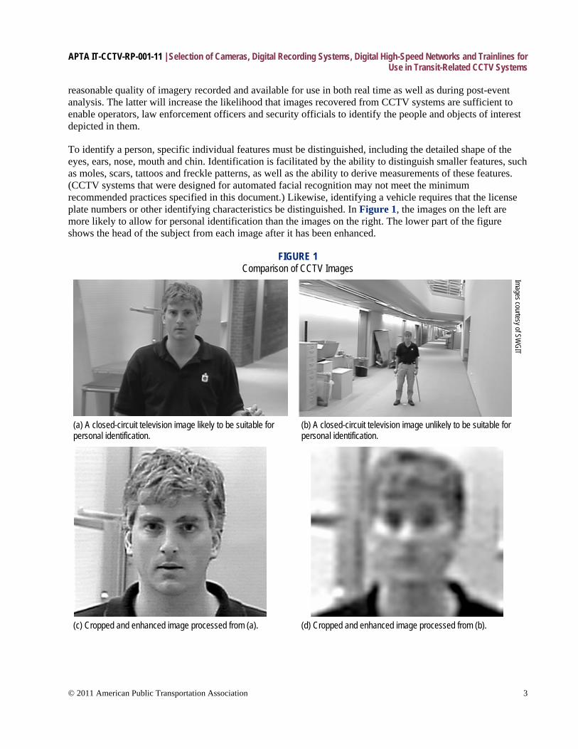
To identify a person, specific individual features must be distinguished, including the detailed shape of the eyes, ears, nose, mouth and chin. Identification is facilitated by the ability to distinguish smaller features, such as moles, scars, tattoos and freckle patterns, as well as the ability to derive measurements of these features. (CCTV systems that were designed for automated facial recognition may not meet the minimum recommended practices specified in this document.) Likewise, identifying a vehicle requires that the license plate numbers or other identifying characteristics be distinguished. In Figure 1, the images on the left are more likely to allow for personal identification than the images on the right. The lower part of the figure shows the head of the subject from each image after it has been enhanced.
FIGURE 1 Comparison of CCTV Images
Images courtesy of SWGIT
(a) A closed-circuit television image likely to be suitable for personal identification.
(b) A closed-circuit television image unlikely to be suitable for personal identification.
(c) Cropped and enhanced image processed from (a). (d) Cropped and enhanced image processed from (b).
APTA IT-CCTV-RP-001-11 | Selection of Cameras, Digital Recording Systems, Digital High-Speed Networks and Trainlines for Use in Transit-Related CCTV Systems
© 2011 American Public Transportation Association 4
2.2 Systems design The ability of a CCTV system to record images that will be of greatest assistance to both operators and law enforcement agencies depends on multiple factors, including the choice and placement of cameras and lenses, recorders, storage space and compression schemes (codecs). The placement of cameras is dealt with in other APTA Recommended Practices. However, these factors are not independent of one another and must be coordinated. As an example, adding cameras to an existing system will require adjustments to the amount of storage or the rate at which images from each camera are recorded. In the case of an IP camera installation, a review of the associated network that connects them will be required. Older wiring systems and networks may well be bandwidth restricted and limit the amount of digitized image data that can be transmitted over the network. This makes the use of local digital recording systems of even greater importance in preserving high-resolution images.
A careful survey of the facility or vehicle in which the system will be installed must be completed and analyzed as an integral part of the total system design process and risk assessment. A site plan or vehicle layout plan documenting the location and field of view of each camera in the system should be included as a part of this survey. If possible, digital photos or screen shots from a pole-mounted mobile camera should be used. Finally, upon installation, the system must be tested to confirm that images produced by the system as output (i.e., those that would be both observed by operators as well as recorded images provided to law enforcement in the event of any potential criminal investigation) are of sufficient quality to maximize the likelihood of identifying people or objects depicted in them.
Camera design and system architecture must be carefully considered as part of the overall process of the design of the system. It is essential that a statement of needs is developed to ensure that the system meets the requirements of the agency installing and operating the system. The following design statements should be considered:
• Why are we installing a CCTV system? • What is the main use of the system (crime prevention, revenue protection, counterterrorism, etc.)? • Where do I need to install cameras and why (fields of view, protection, etc.)? • What are the images meant to achieve (identify, monitor, etc.)? • What recording system and backup facility will I need?
Once the number of locations has been agreed to, the type, frame rate and resolution of the cameras needed must be decided. This will lead to a fundamental decision on the type of cameras to be used, and the appropriate compression algorithm. The use, or purpose, of cameras will fall into one or more of the following four general areas of application:
• detect • monitor • recognize • identify
These categories will later be used to validate the effectiveness of the CCTV system during testing, as each type of camera has a different resolution requirement that will need to be demonstrated during playback of a recorded image, rather than via viewing of any “native” camera output on a monitor. Depending on the classification of the camera, resolution targets such as the Rotakin chart may be used to define these parameters during the testing and commissioning of the CCTV system, and also after additions are made to a system. It should be noted that most resolution targets are well suited to analog camera systems, and new test targets are currently being developed to further define features that are specific to digital camera systems.
APTA IT-CCTV-RP-001-11 | Selection of Cameras, Digital Recording Systems, Digital High-Speed Networks and Trainlines for Use in Transit-Related CCTV Systems
© 2011 American Public Transportation Association 5
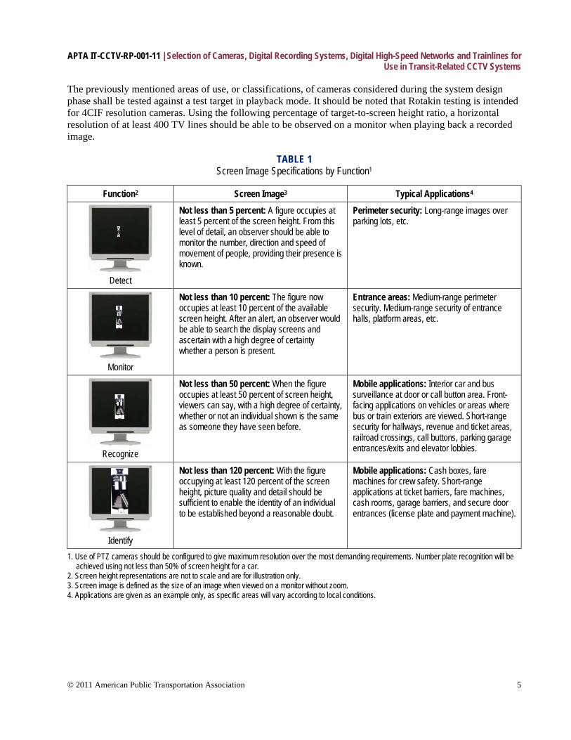
The previously mentioned areas of use, or classifications, of cameras considered during the system design phase shall be tested against a test target in playback mode. It should be noted that Rotakin testing is intended for 4CIF resolution cameras. Using the following percentage of target-to-screen height ratio, a horizontal resolution of at least 400 TV lines should be able to be observed on a monitor when playing back a recorded image.
TABLE 1 Screen Image Specifications by Function1
Function2 Screen Image3 Typical Applications4
Detect
Not less than 5 percent: A figure occupies at least 5 percent of the screen height. From this level of detail, an observer should be able to monitor the number, direction and speed of movement of people, providing their presence is known.
Perimeter security: Long-range images over parking lots, etc.
Monitor
Not less than 10 percent: The figure now occupies at least 10 percent of the available screen height. After an alert, an observer would be able to search the display screens and ascertain with a high degree of certainty whether a person is present.
Entrance areas: Medium-range perimeter security. Medium-range security of entrance halls, platform areas, etc.
Recognize
Not less than 50 percent: When the figure occupies at least 50 percent of screen height, viewers can say, with a high degree of certainty, whether or not an individual shown is the same as someone they have seen before.
Mobile applications: Interior car and bus surveillance at door or call button area. Front-facing applications on vehicles or areas where bus or train exteriors are viewed. Short-range security for hallways, revenue and ticket areas, railroad crossings, call buttons, parking garage entrances/exits and elevator lobbies.
Identify
Not less than 120 percent: With the figure occupying at least 120 percent of the screen height, picture quality and detail should be sufficient to enable the identity of an individual to be established beyond a reasonable doubt.
Mobile applications: Cash boxes, fare machines for crew safety. Short-range applications at ticket barriers, fare machines, cash rooms, garage barriers, and secure door entrances (license plate and payment machine).
1. Use of PTZ cameras should be configured to give maximum resolution over the most demanding requirements. Number plate recognition will be achieved using not less than 50% of screen height for a car.
2. Screen height representations are not to scale and are for illustration only. 3. Screen image is defined as the size of an image when viewed on a monitor without zoom. 4. Applications are given as an example only, as specific areas will vary according to local conditions.
APTA IT-CCTV-RP-001-11 | Selection of Cameras, Digital Recording Systems, Digital High-Speed Networks and Trainlines for Use in Transit-Related CCTV Systems
© 2011 American Public Transportation Association 6
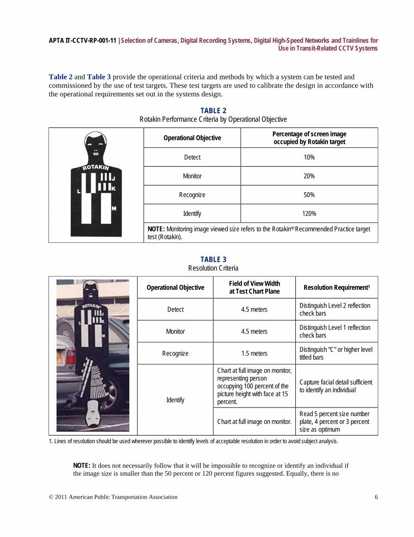
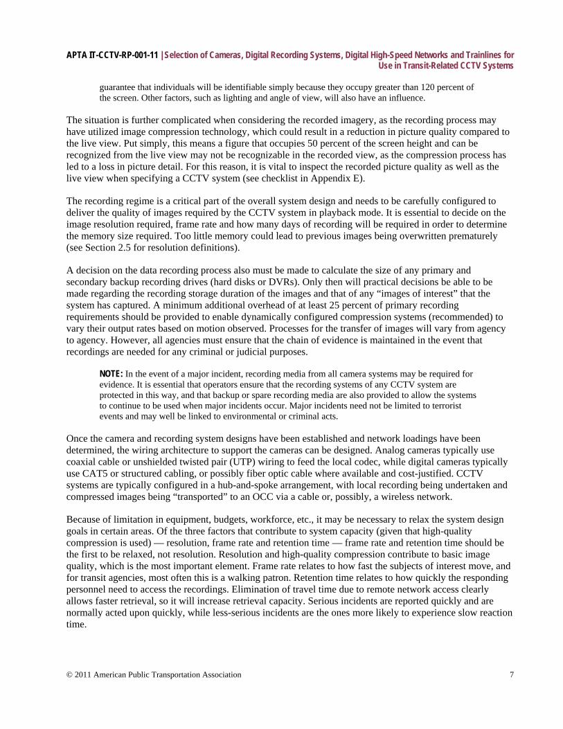
Table 2 and Table 3 provide the operational criteria and methods by which a system can be tested and commissioned by the use of test targets. These test targets are used to calibrate the design in accordance with the operational requirements set out in the systems design.
TABLE 2 Rotakin Performance Criteria by Operational Objective
Operational Objective Percentage of screen image occupied by Rotakin target
Detect 10%
Monitor 20%
Recognize 50%
Identify 120%
NOTE: Monitoring image viewed size refers to the Rotakin® Recommended Practice target test (Rotakin).
TABLE 3 Resolution Criteria
Operational Objective Field of View Width at Test Chart Plane Resolution Requirement1
Detect 4.5 meters Distinguish Level 2 reflection check bars
Monitor 4.5 meters Distinguish Level 1 reflection check bars
Recognize 1.5 meters Distinguish “C” or higher level titled bars
Identify
Chart at full image on monitor, representing person occupying 100 percent of the picture height with face at 15 percent.
Capture facial detail sufficient to identify an individual
Chart at full image on monitor. Read 5 percent size number plate, 4 percent or 3 percent size as optimum
1. Lines of resolution should be used wherever possible to identify levels of acceptable resolution in order to avoid subject analysis.
NOTE: It does not necessarily follow that it will be impossible to recognize or identify an individual if the image size is smaller than the 50 percent or 120 percent figures suggested. Equally, there is no
APTA IT-CCTV-RP-001-11 | Selection of Cameras, Digital Recording Systems, Digital High-Speed Networks and Trainlines for Use in Transit-Related CCTV Systems
© 2011 American Public Transportation Association 7
guarantee that individuals will be identifiable simply because they occupy greater than 120 percent of the screen. Other factors, such as lighting and angle of view, will also have an influence.
The situation is further complicated when considering the recorded imagery, as the recording process may have utilized image compression technology, which could result in a reduction in picture quality compared to the live view. Put simply, this means a figure that occupies 50 percent of the screen height and can be recognized from the live view may not be recognizable in the recorded view, as the compression process has led to a loss in picture detail. For this reason, it is vital to inspect the recorded picture quality as well as the live view when specifying a CCTV system (see checklist in Appendix E).
The recording regime is a critical part of the overall system design and needs to be carefully configured to deliver the quality of images required by the CCTV system in playback mode. It is essential to decide on the image resolution required, frame rate and how many days of recording will be required in order to determine the memory size required. Too little memory could lead to previous images being overwritten prematurely (see Section 2.5 for resolution definitions).
A decision on the data recording process also must be made to calculate the size of any primary and secondary backup recording drives (hard disks or DVRs). Only then will practical decisions be able to be made regarding the recording storage duration of the images and that of any “images of interest” that the system has captured. A minimum additional overhead of at least 25 percent of primary recording requirements should be provided to enable dynamically configured compression systems (recommended) to vary their output rates based on motion observed. Processes for the transfer of images will vary from agency to agency. However, all agencies must ensure that the chain of evidence is maintained in the event that recordings are needed for any criminal or judicial purposes.
NOTE: In the event of a major incident, recording media from all camera systems may be required for evidence. It is essential that operators ensure that the recording systems of any CCTV system are protected in this way, and that backup or spare recording media are also provided to allow the systems to continue to be used when major incidents occur. Major incidents need not be limited to terrorist events and may well be linked to environmental or criminal acts.
Once the camera and recording system designs have been established and network loadings have been determined, the wiring architecture to support the cameras can be designed. Analog cameras typically use coaxial cable or unshielded twisted pair (UTP) wiring to feed the local codec, while digital cameras typically use CAT5 or structured cabling, or possibly fiber optic cable where available and cost-justified. CCTV systems are typically configured in a hub-and-spoke arrangement, with local recording being undertaken and compressed images being “transported” to an OCC via a cable or, possibly, a wireless network.
Because of limitation in equipment, budgets, workforce, etc., it may be necessary to relax the system design goals in certain areas. Of the three factors that contribute to system capacity (given that high-quality compression is used) — resolution, frame rate and retention time — frame rate and retention time should be the first to be relaxed, not resolution. Resolution and high-quality compression contribute to basic image quality, which is the most important element. Frame rate relates to how fast the subjects of interest move, and for transit agencies, most often this is a walking patron. Retention time relates to how quickly the responding personnel need to access the recordings. Elimination of travel time due to remote network access clearly allows faster retrieval, so it will increase retrieval capacity. Serious incidents are reported quickly and are normally acted upon quickly, while less-serious incidents are the ones more likely to experience slow reaction time.
APTA IT-CCTV-RP-001-11 | Selection of Cameras, Digital Recording Systems, Digital High-Speed Networks and Trainlines for Use in Transit-Related CCTV Systems
© 2011 American Public Transportation Association 8
A transit authority may legitimately decide to risk losing less-serious evidence in order to reduce costs and system overhead. In addition, having a published fixed maximum retention time may be beneficial for some to quickly determine whether the evidence is obtainable. For these reasons, retention times less than 31 days may be deemed appropriate, given that an agency has procedures and processes in place to allow for the appropriate review of images within these minimum time frames.
Where no local or state requirements, laws or procedures exist for retention of digital multimedia evidence (DME), the above recommendation should be used. Agencies with processes or procedures that allow for shorter retention periods may be used in place of the above recommendations, provided that the operator’s general management agrees to this variation.
Other factors are also important in the system design, such as lighting the areas covered by the CCTV system. These are dealt with in the subsections below, along with other considerations, such as signal-to-noise ratio (SNR), electrical noise, etc.
2.3 Black-and-white versus color cameras Although black-and-white video cameras may provide better image resolution than color cameras, the information available in color images may provide important investigative information. Therefore, the choice of cameras is left to the operator, dependent on the intended use of the recorded images. 4CIF cameras are commonly available in monochrome; however, it is strongly recommend that color cameras be used wherever possible. In many applications, color fidelity is important, so it is essential that the proper white balance mode is selected for the camera at the time of installation in order to compensate for the color temperature of the ambient lighting. It is also important that the camera accurately and automatically performs white balancing on a real-time basis.
2.4 Exposure control Cameras should be equipped with automatic mechanisms to ensure proper exposure under varying lighting conditions. Such mechanisms include, but are not limited to, automatic gain circuitry, day/night sensor switching and lenses with automatic iris functions. Cameras that have manual iris functions can require manual reconfiguration when lighting levels change. As such, it is recommended that cameras that support auto iris or electronic shuttering be used. Partial exposure occurs when a flash of light appears in the scene and is not synchronized to the exposure. Again, this occurs quite often in transportation-related installations, so the type of shuttering used by the image sensor should be one of the criteria used in the camera selection process.
In transit systems, it is also desirable to capture the state of traffic signals and dashboard-mounted status indicators for forensic purposes. There has been a recent transition from incandescent lamps to the use of LEDs for traffic control signals, and some of these are pulse-width modulated to reduce the total amount of power used, as well as to increase the life of the bulbs. Likewise, LED status indicators on dashboards are often pulse-width modulated. This means that although the human eye sees them in a state of constant illumination, they are actually dark at times. It is important in these applications to select a camera that supports an exposure mode that compensates for this and always captures the true state of the signal or indicator.
2.5 Camera resolution Resolution is the ability to resolve or see small details in an image. Resolution for CCTV cameras (as well as for TV monitors and recorders) is a monochrome specification that specifies how many black-and-white lines can be seen in a given area and is specified in terms of lines of horizontal resolution. For images with 4:3
APTA IT-CCTV-RP-001-11 | Selection of Cameras, Digital Recording Systems, Digital High-Speed Networks and Trainlines for Use in Transit-Related CCTV Systems
© 2011 American Public Transportation Association 9
aspect ratios, horizontal resolution is defined as the number of vertical black-and-white lines one can discern in three-quarters of the picture width. CCTV cameras range from 200 to more than 1,000 lines of horizontal resolution. Higher-resolution cameras generally cost more than lower-resolution cameras. Note that care must be taken to preserve the aspect ratio between the camera and the display so as to avoid a loss of image in display transition.
Color analog video cameras must have an output resolution of at least 480 horizontal TV lines and use a compression regime that enables the minimum playback resolution requirements to be achieved. Color digital video cameras must have an output resolution meeting the requirements of at least 4CIF (704 vertical pixels × 576 horizontal pixels), and any camera-based compression architectures must, as with analog cameras, enable the playback resolution requirements to be met. It is strongly recommended that, wherever possible, all cameras should have higher resolution capabilities.
2.5.1 About pixels “Pixel,” or active picture element, is a term used specifically with cameras and is directly related to horizontal lines of resolution. Pixels are the actual number of light-sensitive elements that are within the camera-imaging device. Pixels are expressed with a horizontal number (the number of elements horizontally across the imager device) and a vertical number (the number of elements vertically on the imager). A camera specified with 768H by 494V picture elements has 494 rows of picture elements vertically, with each row having 768 elements horizontally.
CIF is used to standardize the horizontal and vertical resolutions in pixels of YCbCr sequences in video signals. It was designed to be easy to convert to PAL or NTSC recommended practices.
2.6 Camera frame rates Frame rate, or frame frequency, is the measurement of how quickly an imaging device (camera) produces unique, consecutive images called frames. The term applies equally well to computer graphics, video cameras, film cameras and motion capture systems. Frame rate is most often expressed in frames per second, or simply hertz (Hz). The frame rate is not a measure of the quality of the image, which is achieved by resolution (see Section 2.5), but a measure of how any given scene is captured in terms of motion. The more frames per second used, the more information is available regarding motion. Full-motion video is achieved at approximately 22 to 24 fps when viewed by the human eye.
A minimum of 5 fps (4 fps for PAL-based systems) is recommended in low-traffic areas or areas where only walking-pace motion is likely. Fifteen fps (12 fps) should be used in where cameras are covering trackside operations or areas where fast-moving objects are likely to be observed. Where motor vehicles or external images from vehicles are recorded, 30 fps (25 fps) should be specified.
Where cameras are covering passenger areas or areas containing any form of emergency call button, a two-speed capability must be incorporated into the cameras’ codec to provide 5 fps (4 fps in PAL-based systems) in normal mode, and a minimum of 15 fps (12 fps) in emergency mode. Where a compression codec is to be used without two-speed capability, the higher 15 fps (12 fps) rate should be used to provide full-motion video recording capability.
APTA IT-CCTV-RP-001-11 | Selection of Cameras, Digital Recording Systems, Digital High-Speed Networks and Trainlines for Use in Transit-Related CCTV Systems
© 2011 American Public Transportation Association 10
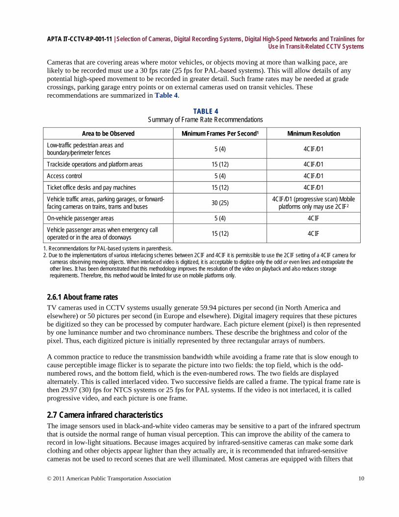
Cameras that are covering areas where motor vehicles, or objects moving at more than walking pace, are likely to be recorded must use a 30 fps rate (25 fps for PAL-based systems). This will allow details of any potential high-speed movement to be recorded in greater detail. Such frame rates may be needed at grade crossings, parking garage entry points or on external cameras used on transit vehicles. These recommendations are summarized in Table 4.
TABLE 4 Summary of Frame Rate Recommendations
Area to be Observed Minimum Frames Per Second1 Minimum Resolution
Low-traffic pedestrian areas and boundary/perimeter fences 5 (4) 4CIF/D1
Trackside operations and platform areas 15 (12) 4CIF/D1
Access control 5 (4) 4CIF/D1
Ticket office desks and pay machines 15 (12) 4CIF/D1
Vehicle traffic areas, parking garages, or forward-facing cameras on trains, trams and buses 30 (25) 4CIF/D1 (progressive scan) Mobile
platforms only may use 2CIF2
On-vehicle passenger areas 5 (4) 4CIF
Vehicle passenger areas when emergency call operated or in the area of doorways 15 (12) 4CIF
1. Recommendations for PAL-based systems in parenthesis. 2. Due to the implementations of various interlacing schemes between 2CIF and 4CIF it is permissible to use the 2CIF setting of a 4CIF camera for
cameras observing moving objects. When interlaced video is digitized, it is acceptable to digitize only the odd or even lines and extrapolate the other lines. It has been demonstrated that this methodology improves the resolution of the video on playback and also reduces storage requirements. Therefore, this method would be limited for use on mobile platforms only.
2.6.1 About frame rates TV cameras used in CCTV systems usually generate 59.94 pictures per second (in North America and elsewhere) or 50 pictures per second (in Europe and elsewhere). Digital imagery requires that these pictures be digitized so they can be processed by computer hardware. Each picture element (pixel) is then represented by one luminance number and two chrominance numbers. These describe the brightness and color of the pixel. Thus, each digitized picture is initially represented by three rectangular arrays of numbers.
A common practice to reduce the transmission bandwidth while avoiding a frame rate that is slow enough to cause perceptible image flicker is to separate the picture into two fields: the top field, which is the odd-numbered rows, and the bottom field, which is the even-numbered rows. The two fields are displayed alternately. This is called interlaced video. Two successive fields are called a frame. The typical frame rate is then 29.97 (30) fps for NTCS systems or 25 fps for PAL systems. If the video is not interlaced, it is called progressive video, and each picture is one frame.
2.7 Camera infrared characteristics The image sensors used in black-and-white video cameras may be sensitive to a part of the infrared spectrum that is outside the normal range of human visual perception. This can improve the ability of the camera to record in low-light situations. Because images acquired by infrared-sensitive cameras can make some dark clothing and other objects appear lighter than they actually are, it is recommended that infrared-sensitive cameras not be used to record scenes that are well illuminated. Most cameras are equipped with filters that
APTA IT-CCTV-RP-001-11 | Selection of Cameras, Digital Recording Systems, Digital High-Speed Networks and Trainlines for Use in Transit-Related CCTV Systems
© 2011 American Public Transportation Association 11
mitigate this effect by blocking infrared light. If infrared-sensitive cameras are required for specific applications, they should be specified in the system documentation.
Infrared-sensitive cameras are specifically selected to operate at the near infrared end of the light spectrum. These cameras may also require additional infrared lighting to be installed. It is essential that such lighting be installed such that it operates in a manner that is safe for the eyes of humans and animals, since the eye’s iris will adjust only to the intensity of visible light. Note that it is actually possible to burn the retina or even cause blindness by looking at an infrared light source for an extended period of time.
2.8 Lenses 2.8.1 Field of view The field of view (FOV) is the size of the observable area captured by the camera using a specific lens. If the field of view is not suitable, you may consider using a different lens (wide-angle, telephoto, etc.) to increase or decrease the field of view. Camera lenses can be divided into two basic types: fixed focal and varifocal (sometimes known as zoom). A fixed focal lens has a constant focal length, while a varifocal lens can change its focal length. Focal length is simply the distance from the optical center of the lens to a focal point near the back of the lens. This distance is written on the lens and expressed in millimeters. Fixed focal length lenses are available in various wide, medium and narrow fields of view. A lens with a “normal” focal length produces a picture that approximates the field of view of the human eye. A wide-angle lens has a short focal length, while a telephoto lens has a long focal length. When selecting a fixed lens for a particular view, bear in mind that if you want to change the field of view, you must change the lens.
When both wide scenes and close-up scenes are needed, a varifocal lens is best. A zoom lens is an assembly of lens elements that changes the focal length from a wide angle to a telephoto while maintaining focus on the camera’s imager. This permits you to change the field of view between narrow, medium and wide angles.
2.8.2 F-stop At a given shutter speed, the ability of a lens to gather light depends on the relationship between the lens opening (aperture) and the focal length. This relationship is symbolized by the letter “f,” is commonly referred to as the “f-stop,” and can be found printed on the side or front of the lens. The f-stop is a ratio between the focal length and the lens aperture. For example, for a lens with a 12 mm focal length, the aperture is 6 mm in diameter at f/2.0 and 12 mm in diameter at f/1.0.
The lower the f-stop number, the larger the maximum lens aperture, the greater the lens’ ability to pass light to the camera imager, and the better it can view a low-light scene. For example, a lens with an f-stop of f/1.2 can gather a great deal more light than a lens with an f-stop of f/4.0. A lens with a low f-stop number is sometimes also called a “fast lens.” Conversely, the higher the f-stop, the smaller the aperture and the less light passes through the lens. An increase of one full f-stop (e.g., f/2.0 to f/1.4) doubles the amount of light that will pass through a lens to the imager.

APTA IT-CCTV-RP-001-11 | Selection of Cameras, Digital Recording Systems, Digital High-Speed Networks and Trainlines for Use in Transit-Related CCTV Systems
© 2011 American Public Transportation Association 12
FIGURE 2 F-Stop Calculation and Examples
Minimum illumination: 0.4 lux @ 30 IRE, f/1.2
F-stop = Focal Length (mm) / Diameter of Iris Opening (mm)
f/1.0 f/1.4 f/2.0 Diagram is not to scale and is for illustration only.
2.8.3 Depth of field Another consideration when determining the proper lens is depth of field. Depth of field is the range of distance within the image that is acceptably sharp. This means that, when you focus precisely on a subject, a certain distance in front of and behind the subject also will be in focus, although not necessarily as sharp. Depth of field increases or decreases based on the focal length of the lens, the distance to the subject, and the aperture.
TABLE 5 Depth of Field Relationships
Lens length Short lens (wide-angle lens) Longer depth of field
Long lens (telephoto) Shorter depth of field
Aperture Wide aperture (low f-stop) Shorter depth of field
Narrow aperture (high f-stop) Longer depth of field
Distance to object Short distance Shorter depth of field
Long distance Longer depth of field
In a well-lit situation with a lens set to a higher f-stop, a greater area in front of and behind the subject will be in focus. As light levels drop and the lens adjusts to a lower f-stop (assuming an auto-iris lens), less of the area in front of and behind the subject will be in focus. Thus, depth of field and lighting conditions must both be selected when selecting cameras and lenses. An auto-iris lens is designed to automatically increase the size of the aperture as the view becomes darker (such as when the sun goes down) to maintain a viewable image. As this happens, the depth of field will decrease proportionally, and some objects in the scene, generally in front of and behind the center of the scene, will go out of focus.
In areas where all objects in the scene are critical, cameras designed to operate in very low light or supplemental illumination may be required. In very critical areas, separate cameras may be required to view each portion of the scene to maintain proper focus.
APTA IT-CCTV-RP-001-11 | Selection of Cameras, Digital Recording Systems, Digital High-Speed Networks and Trainlines for Use in Transit-Related CCTV Systems
© 2011 American Public Transportation Association 13
FIGURE 3 Depth of Field Illustration
f/1.8
f/4.0
The selection of lenses will be dictated by the field of view to be covered by each camera, as well as by the camera’s optical format. (Optical format is the commonly used term and is more correct than “detector size,” although the size of the sensor and the optical format must be matched.)
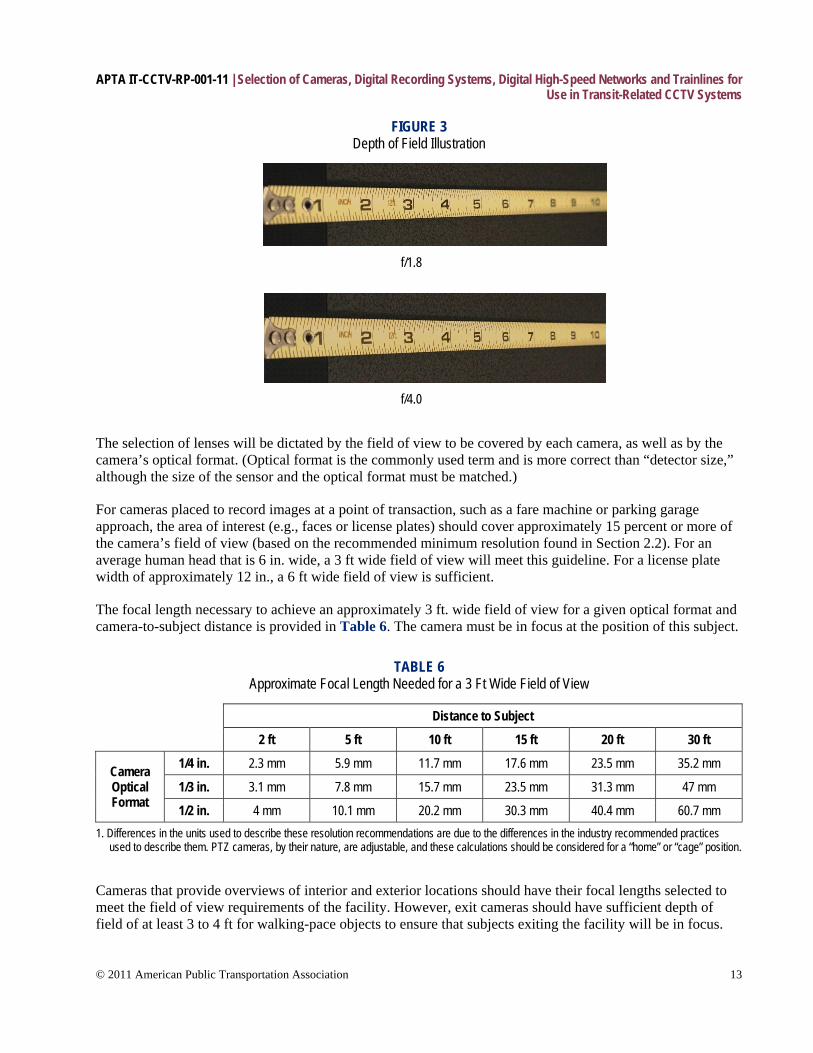
For cameras placed to record images at a point of transaction, such as a fare machine or parking garage approach, the area of interest (e.g., faces or license plates) should cover approximately 15 percent or more of the camera’s field of view (based on the recommended minimum resolution found in Section 2.2). For an average human head that is 6 in. wide, a 3 ft wide field of view will meet this guideline. For a license plate width of approximately 12 in., a 6 ft wide field of view is sufficient.
The focal length necessary to achieve an approximately 3 ft. wide field of view for a given optical format and camera-to-subject distance is provided in Table 6. The camera must be in focus at the position of this subject.
TABLE 6 Approximate Focal Length Needed for a 3 Ft Wide Field of View
Distance to Subject
2 ft 5 ft 10 ft 15 ft 20 ft 30 ft
Camera Optical Format
1/4 in. 2.3 mm 5.9 mm 11.7 mm 17.6 mm 23.5 mm 35.2 mm
1/3 in. 3.1 mm 7.8 mm 15.7 mm 23.5 mm 31.3 mm 47 mm
1/2 in. 4 mm 10.1 mm 20.2 mm 30.3 mm 40.4 mm 60.7 mm 1. Differences in the units used to describe these resolution recommendations are due to the differences in the industry recommended practices
used to describe them. PTZ cameras, by their nature, are adjustable, and these calculations should be considered for a “home” or “cage” position.
Cameras that provide overviews of interior and exterior locations should have their focal lengths selected to meet the field of view requirements of the facility. However, exit cameras should have sufficient depth of field of at least 3 to 4 ft for walking-pace objects to ensure that subjects exiting the facility will be in focus.
APTA IT-CCTV-RP-001-11 | Selection of Cameras, Digital Recording Systems, Digital High-Speed Networks and Trainlines for Use in Transit-Related CCTV Systems
© 2011 American Public Transportation Association 14
2.8.4 Background field of view (FOV) FOV relates to the size of the area that a camera will see at a specific distance from the camera. It is dependent on lens focal length and a camera’s optical format size. The FOV width and height can be calculated using the following formulas:
FOV Width = Format (horizontal in mm) × Distance (in feet from camera) / Focal Length
FOV Height = 0.75 × FOV Width
Format refers to optical format and in this case is the horizontal width of the camera’s image sensor. The horizontal dimensions for common optical formats:
• 2/3 in.: 8.8 mm • 1/2 in.: 6.4 mm • 1/3 in.: 4.8 mm • 1/4 in.: 3.2 mm • 1/6 in.: 2.4 mm
Manipulating the FOV formula allows a calculation of the distance in feet from the camera for a required FOV width. The formula becomes:
Distance (in feet from camera) = FOV Width × Focal Length / Format (horizontal in mm)
Fisheye lenses are being used in a number of transit applications as a compromise for the number of cameras being used, especially in mobile applications. The use of such lenses is not recommended, as they introduce distortion into the image that is difficult to resolve when considering the relationships in different parts of the observed area.
2.9 Wireless (IP) cameras Many new camera systems are now increasingly available as IP cameras, and some of these support megapixel resolutions. These cameras output digital data over a network (e.g., 100 Base-T Ethernet) and therefore already contain the compression algorithm within the camera to modify the output to digital and allow the output to be transmitted over an appropriate network, such as Ethernet 10/100 Base-T.
Caution must be exercised when considering wireless IP-based cameras to ensure that the resolution and compression architectures can meet the system design requirements for that location. IP cameras are useful in remote locations. However, unless a transit agency is using a high-bandwidth and encrypted radio wireless link, care must be taken to record the output of the camera locally in high resolution, rather than at the OCC, where the signal would normally be transmitted in a reduced resolution to optimize network traffic considerations.
There are many reasons for this. Capacity issues, or interference on the radio network, may well restrict transmission capability and possibly cause corruption of the image file. Public unlicensed frequencies are prone to capacity issues, as well as potential loss of signal. For this reason, images that originate from wireless camera locations and have no local recording may be useful only for observation or situation awareness, and may not be admissible in court due to chain of evidence requirements and use of a public frequency.
APTA IT-CCTV-RP-001-11 | Selection of Cameras, Digital Recording Systems, Digital High-Speed Networks and Trainlines for Use in Transit-Related CCTV Systems
© 2011 American Public Transportation Association 15
Caution must also be exercised when considering the compression architecture employed in the IP camera, as this may well have to be optimized for commercial applications where data transmission rate is paramount, as opposed to quality/resolution and frame rate of the image.
2.10 Remote view cameras The viewing of any given camera from a remote location may well prove to be of extreme use in a tactical situation. Mobile platforms, particularly, can be configured to output their images via a wireless or microwave network for a variety of reasons, such as security, safety, or — in an emergency situation — to allow first responders to assess the situation on a vehicle or in a sensitive static location, such as a cash room, etc.
Facilities for transmitting images from a mobile platform should be considered in any system design, and appropriate consideration should be given to the control of various onboard cameras remotely. These facilities should not interfere with the main requirements of the CCTV system and should be able to be operated and fully instigated remotely, without the need for local operator intervention. Wireless frequencies used for this purpose need to be assessed for availability, bandwidth, capacity and potential jamming or interference.
2.11 Lighting Poor lighting is the most common factor that degrades the quality of video images. Adequate, balanced lighting should be provided in areas viewed by the cameras wherever possible. Open indoor/outdoor building design of stations, platforms and depots, as well as onboard transit cameras, are particularly challenging because of the changing lighting conditions inherent in the location. Particular care must be taken to ensure that the dynamic range (the ratio of the lightest highlights to darkest shadow portions of the scene) does not exceed the capability of the camera to record it. If low dynamic range cameras (less than 75 dB) are used in the installation, flares or silhouettes may appear in the video as a result.
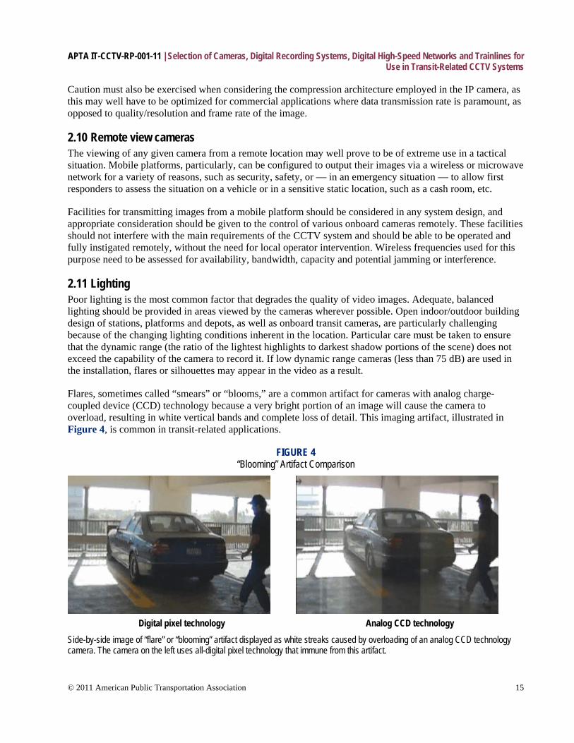
Flares, sometimes called “smears” or “blooms,” are a common artifact for cameras with analog charge-coupled device (CCD) technology because a very bright portion of an image will cause the camera to overload, resulting in white vertical bands and complete loss of detail. This imaging artifact, illustrated in Figure 4, is common in transit-related applications.
FIGURE 4 “Blooming” Artifact Comparison
Digital pixel technology Analog CCD technology
Side-by-side image of “flare” or “blooming” artifact displayed as white streaks caused by overloading of an analog CCD technology camera. The camera on the left uses all-digital pixel technology that immune from this artifact.
APTA IT-CCTV-RP-001-11 | Selection of Cameras, Digital Recording Systems, Digital High-Speed Networks and Trainlines for Use in Transit-Related CCTV Systems
© 2011 American Public Transportation Association 16
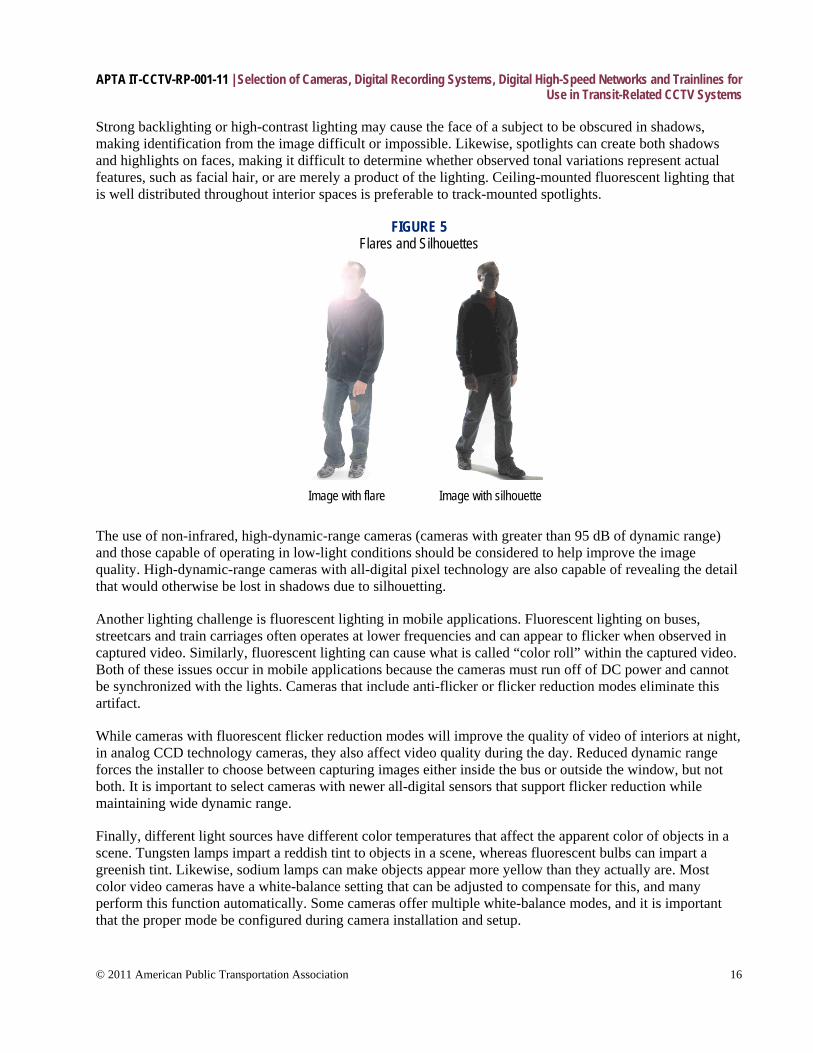
Strong backlighting or high-contrast lighting may cause the face of a subject to be obscured in shadows, making identification from the image difficult or impossible. Likewise, spotlights can create both shadows and highlights on faces, making it difficult to determine whether observed tonal variations represent actual features, such as facial hair, or are merely a product of the lighting. Ceiling-mounted fluorescent lighting that is well distributed throughout interior spaces is preferable to track-mounted spotlights.
FIGURE 5 Flares and Silhouettes
Image with flare Image with silhouette
The use of non-infrared, high-dynamic-range cameras (cameras with greater than 95 dB of dynamic range) and those capable of operating in low-light conditions should be considered to help improve the image quality. High-dynamic-range cameras with all-digital pixel technology are also capable of revealing the detail that would otherwise be lost in shadows due to silhouetting.
Another lighting challenge is fluorescent lighting in mobile applications. Fluorescent lighting on buses, streetcars and train carriages often operates at lower frequencies and can appear to flicker when observed in captured video. Similarly, fluorescent lighting can cause what is called “color roll” within the captured video. Both of these issues occur in mobile applications because the cameras must run off of DC power and cannot be synchronized with the lights. Cameras that include anti-flicker or flicker reduction modes eliminate this artifact.
While cameras with fluorescent flicker reduction modes will improve the quality of video of interiors at night, in analog CCD technology cameras, they also affect video quality during the day. Reduced dynamic range forces the installer to choose between capturing images either inside the bus or outside the window, but not both. It is important to select cameras with newer all-digital sensors that support flicker reduction while maintaining wide dynamic range.
Finally, different light sources have different color temperatures that affect the apparent color of objects in a scene. Tungsten lamps impart a reddish tint to objects in a scene, whereas fluorescent bulbs can impart a greenish tint. Likewise, sodium lamps can make objects appear more yellow than they actually are. Most color video cameras have a white-balance setting that can be adjusted to compensate for this, and many perform this function automatically. Some cameras offer multiple white-balance modes, and it is important that the proper mode be configured during camera installation and setup.

APTA IT-CCTV-RP-001-11 | Selection of Cameras, Digital Recording Systems, Digital High-Speed Networks and Trainlines for Use in Transit-Related CCTV Systems
© 2011 American Public Transportation Association 17
A color video camera is considered balanced for a particular reference white when a neutral white card is placed in the camera’s field of view under normal illumination conditions, and the red, green and blue channels provide equal output levels. Therefore, interior color cameras should be balanced for white on installation and rebalanced if the lighting type is changed. However, because many installations will operate under conditions in which lighting is variable, white balance may not be possible at all times.
Infrared lighting can be used to provide improved low-light performance for monochrome cameras. Infrared lighting is not recommended for use with color cameras, as they filter out the infrared spectrum. If an infrared-sensitive video camera is used, any person reviewing the imagery should be made aware of this, because an infrared-sensitive video camera often reproduces images, particularly of colored materials, that appear to be dramatically differently when compared to images of the same materials recorded with a video camera not sensitive to infrared.
2.12 Camera housings Cameras in transit applications will require coverings and environmental controls to protect them from the elements (heating, cooling, etc.) or tampering. Clear coverings placed in front of camera lenses will reduce image quality unless regularly inspected, maintained and cleaned. Where these are required, it is essential that any material used to cover the lens aperture resist scratching or damage by impact to reduce the effects on the quality of the image.
It is recommended that camera housings have a regular preventative maintenance schedule developed in order to maintain the clarity of images and thus the effectiveness of the system.
Caution should be used when considering camera housings for tunnel locations, particularly in metro systems, due to the presence of corrosive brake dust, etc.
2.12.1 NEMA environmental ratings The National Electrical Manufacturers Association (NEMA) has developed a comprehensive set of specifications and ratings for indoor and outdoor electrical housings. Many of the manufacturers of video security housings and integrated camera modules have designed their products to meet some of these housing ratings. Information on these ratings is included in the manufacturers’ literature, and detailed information can be obtained from the NEMA organization. Table 7 summarizes several NEMA housing ratings for indoor and outdoor designs.
TABLE 7 NEMA Housing Ratings for Non-Hazardous Locations
Environmental Condition to be Protected Against
NEMA Enclosure Type1
1 3 4 4X 6 6P 12 13
Approximate IP Equivalent2
IP30 IP64 IP66 IP66 IP65 IP65
Incidental contact with enclosed equipment X X X X X X X X
Indoor X X X X X X X X
Outdoor X X X X
Falling dirt X X X X X X X X
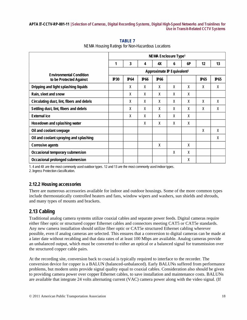
APTA IT-CCTV-RP-001-11 | Selection of Cameras, Digital Recording Systems, Digital High-Speed Networks and Trainlines for Use in Transit-Related CCTV Systems
© 2011 American Public Transportation Association 18
TABLE 7 NEMA Housing Ratings for Non-Hazardous Locations
Environmental Condition to be Protected Against
NEMA Enclosure Type1
1 3 4 4X 6 6P 12 13
Approximate IP Equivalent2
IP30 IP64 IP66 IP66 IP65 IP65
Dripping and light splashing liquids X X X X X X X
Rain, sleet and snow X X X X X
Circulating dust, lint, fibers and debris X X X X X X X
Settling dust, lint, fibers and debris X X X X X X X
External ice X X X X X
Hosedown and splashing water X X X X
Oil and coolant seepage X X
Oil and coolant spraying and splashing X
Corrosive agents X X
Occasional temporary submersion X X
Occasional prolonged submersion X 1. 4 and 4X are the most commonly used outdoor types. 12 and 13 are the most commonly used indoor types. 2. Ingress Protection classification.
2.12.2 Housing accessories There are numerous accessories available for indoor and outdoor housings. Some of the more common types include thermostatically controlled heaters and fans, window wipers and washers, sun shields and shrouds, and many types of mounts and brackets.
2.13 Cabling Traditional analog camera systems utilize coaxial cables and separate power feeds. Digital cameras require either fiber optic or structured copper Ethernet cables and connectors meeting CAT5 or CAT5e standards. Any new camera installation should utilize fiber optic or CAT5e structured Ethernet cabling wherever possible, even if analog cameras are selected. This ensures that a conversion to digital cameras can be made at a later date without recabling and that data rates of at least 100 Mbps are available. Analog cameras provide an unbalanced output, which must be converted to either an optical or a balanced signal for transmission over the structured copper cable pairs.
At the recording site, conversion back to coaxial is typically required to interface to the recorder. The conversion device for copper is a BALUN (balanced-unbalanced). Early BALUNs suffered from performance problems, but modern units provide signal quality equal to coaxial cables. Consideration also should be given to providing camera power over copper Ethernet cables, to save installation and maintenance costs. BALUNs are available that integrate 24 volts alternating current (VAC) camera power along with the video signal. (If
APTA IT-CCTV-RP-001-11 | Selection of Cameras, Digital Recording Systems, Digital High-Speed Networks and Trainlines for Use in Transit-Related CCTV Systems
© 2011 American Public Transportation Association 19
CAT5 cable is used in a UTP installation, then power can be transmitted on unused wire pairs. UTP is the common name for the BALUN-based referred to.)
This is most suitable for indoor fixed cameras typical in transit locations where pan/tilt motors and heaters are not used. Power is injected at the recorder or hub site, where a single 120 VAC feed can power 16 or more cameras. Any future change to digital cameras can utilize the same structured cabling to distribute DC power complying with power over Ethernet (POE) standards. This cabling design for IP cameras requires a hub site within 328 ft (100 m) of the camera to ensure Ethernet performance. [Ref: NVT’s model NV-16PS13-PVD, used by TTC]
Where distances from camera to recorder are in excess of 328 ft (100 m), fiber optic cabling is recommended to ensure future compatibility. For distances up to 1.2 mi (2 km), multimode fiber is preferred to save on equipment costs. For distances exceeding this, single mode fiber is required.
3. Recording systems Recording media used in modern CCTV systems are usually digital in format, enabling the information to be stored on a variety of transferable memory devices, such as flash memory sticks, portable hard drives, fixed hard drives or various CD formats.
Recording capacity is a major issue when designing any CCTV system. Systems design needs to ensure that the recording requirements are sufficient for general operational needs, plus a reasonable percentage of spare capacity (25 percent or more) to account for variations in data transmission caused by variations in compression architectures, which are caused by motion. (Compression architectures are influenced by the amount of motion they “see” in their field of view and will vary their digital output accordingly. Therefore, a “stable” system will record a smaller amount of data from a static view than from a dynamic view that may be present at rush hour, for example.)
Another factor that can significantly affect recording capacity is the camera itself. Compression architectures in today’s DVRs and network video recorders (NVRs) using MPEG-4 or H.264 compression algorithms are sensitive to video noise: The more noise, the larger the file size. Compression algorithms “see” video noise as significant scene motion, and thus cannot compress nearly as well as with a scene with no motion. Cameras that use newer all-digital pixel technology have no analog-to-digital conversion. This reduces random video noise and thus provides better than analog CCD technology based cameras. Depending on the amount of motion in a scene, newer all-digital pixel cameras will provide up to approximately 3 times better compression. Compression efficiency should be one of the criteria evaluated during the camera selection process.
A modern digital camera using a reasonable resolution, compression system and frame rate may well output 1.5 Mbps, plus or minus 25 percent, 5 fps. This would require approximately 15 MB of storage to run for one minute, 900 MB to run for one hour, or 2.16 GB to run for 24 hours on a single camera. A network of 200 cameras operating in a station would typically require 430 GB per day of operation and 14 TB of storage per month. It’s clear that even for modest CCTV systems, the main memory, as well as backup memory, requirements need to be closely monitored to not only meet the needs of the current system, but also meet those of any future expansion. Vehicle-based memory (bus, rail and paratransit) likewise will need to be carefully designed, as these devices must be environmentally protected and are inherently more costly. Because of these environmental conditioning requirements, on-vehicle storage systems will require even more memory.
APTA IT-CCTV-RP-001-11 | Selection of Cameras, Digital Recording Systems, Digital High-Speed Networks and Trainlines for Use in Transit-Related CCTV Systems
© 2011 American Public Transportation Association 20
Analog recording, as well as some digital recording, is still reproduced on conventional VCRs with various types of magnetic storage media covering conventional ferrous oxide tape, as well as various metal tapes. It is not recommended to use VCRs of any type in new CCTV systems, and those used in current CCTV systems should be replaced at an appropriate time in order to allow for recording systems with higher re-recording resolution capabilities, such as DVRs, hard disks and NVRs.
All recording media will rely on the origin of the image, the camera, to provide the best image information (resolution) possible. In all cases, the operational procedures for the handling of CCTV storage media must ensure that appropriate processes are in place to manage the information that the CCTV will produce. Of particular importance will be the management of incident-based recordings — i.e., recordings that contain an incident that needs to be preserved for later use as evidence in civil, criminal or security-related incidents. It is, therefore, worth emphasizing that operators must put in place an appropriate process to handle recorded media in order to satisfy local, state and federal requirements for the chain of evidence. If this is not done, materials produced by the CCTV may not be relied upon in legal terms in the event that CCTV information is required as supporting evidence.
In all cases, a digital signature or hashing method of marking frames outside of the data area must be used. It is not recommended to use watermarking, as some watermarks can alter the image and corrupt the evidence (see Section 3.2.2 for further detail).
3.1 Analog recording systems Due to the reduced resolution of VCR-based recorders, it is recommended that only digital video recording techniques (DVRs, NVRs and hard disk drives) be used in any new transit-based CCTV system.
Time-lapse recording is also a common feature of low-cost, low-resolution, VCR-based systems aimed at economizing tape usage. Time-lapse video recorders also are not recommended for transit-based CCTV systems.
3.2 Digital recorders Recording systems have to take a number of parameters into account in order to provide the optimum recording environment for camera images. Parameters such as compression rate or resolution, frame rate per second, number of cameras and duration all have to be taken into account when considering the capacity of the recording media. Most digital recording systems have a directly proportional relationship between resolution of the image (spatial) versus the frame rate or frames per second (temporal). The one area of variation in this relationship is the compression algorithm configuration, which is dealt with later in this document.
It is recommended that conventional hard drive-based recording systems — conditioned not only for the OCC, but also for mobile applications where appropriate — be used for recording purposes, as these are now cost-effective, robust and scalable. Operators may wish to ensure that backup recording systems are available in the system’s design in the event of failure, as well as a means to transfer images of interest from a hard drive in a vehicle or static location. Such provision should be clearly specified, if required. NVRs also should be considered for larger installations where IP or digital camera systems are used and images are sent back to an OCC. Another method of transferring images is by a removable hard drive. Systems procurement specifications should take into account not only day-to-day requirements for regular transfer of images of interest, but also how these images will be accessed or transferred after a major incident. Care must also be taken to ensure that a process is put in place to administer how images are accessed from drives or DME that has been removed for retention.
APTA IT-CCTV-RP-001-11 | Selection of Cameras, Digital Recording Systems, Digital High-Speed Networks and Trainlines for Use in Transit-Related CCTV Systems
© 2011 American Public Transportation Association 21
3.2.1 Recorder resolution As mentioned in Section 2.6, cameras are specified with the number of lines of horizontal resolution and/or active pixels, depending on whether analog or digital cameras are used in the CCTV system or both. Most security cameras available today range from 300 to 700 lines of horizontal resolution. Black-and-white security cameras commonly have a horizontal resolution of 500 to 700 lines, while color cameras for security applications typically have 300 to 600 lines of resolution. Some camera manufacturers quote resolution in analog lines of resolution as well as pixels for a given camera, identifying the digital equivalent measurement of the sensor.
Digital video recorders using a hard disk or optical disk for storage must record each frame at an appropriate rate of resolution (4CIF/D1 or 2CIF, depending on system design) so that the end-to-end playback capability of the recorded image can achieve not less than the original resolution of the recording when observed on an appropriate monitor and observing a relevant test target.
NOTE: Recompression of images to improve storage capacity may invalidate the ability to present the recorded images as evidence in a court of law.
In order to determine the amount of data from the image to be recorded, a clear understanding of the compression methods used must be made so that artifacts from the compression algorithm do not compromise the resolution of the camera’s image and render any post-event analysis task difficult. Particular care must be taken when considering a compression system that is observing motion, as many compression systems can interfere with this feature.
3.2.2 Digital signatures In order to digitally sign a file, all the data files (in this case, the video) that are to be protected are passed through what is known as a hashing function. This hashing function produces a large checksum value for the file, which is then encrypted using a private key.
A number of different hashing functions are used by digital signature technologies (see FIPS PUB 180-1: “Secure Hash Standard,” April 1995), of which the two most popular are MD5 and SHA1. Digital signatures rely on the near-impossibility of modifying a video file such that the hashing function will produce the same checksum as the unmodified file. For example, with SHA1 there are on the order of 2160 potential checksums! Even modifying a single bit of the video file will change the output from the hashing function.
Digital signatures can be used for authenticating messages in documents sent electronically and, equally, could be adapted for authenticating images. The American Bar Association (Digital Signature Guidelines: http://www.abanet.org/scitech/ec/isc) describes digital signatures as using public key cryptography and a hash function derived from the message itself. The hash function is an algorithm created from enough of the message data to ensure that it could be created only from those data. The message and the hash function are then encrypted with the sender’s private encryption key to make a digital signature, which is unique. The receiver decodes the message with a related version of the encryption key previously given to the intended recipient by the sender (or held by a trusted third party). The message is verified by computing the hash function again and comparing it with the original.
For reference, watermarking is the process of adding information to the actual video content itself. Often the addition of a watermark is designed such that this potentially secret information can be extracted from the video at a later date. A watermark may be designed to be visible for copyrighting, for example, or invisible for content protection or secret communication.

APTA IT-CCTV-RP-001-11 | Selection of Cameras, Digital Recording Systems, Digital High-Speed Networks and Trainlines for Use in Transit-Related CCTV Systems
© 2011 American Public Transportation Association 22
Watermarking is the more traditional approach to protecting video content and has been used extensively in the analog video domain. However, its applicability to the protection of digital video is less justifiable, because digital techniques, such as public key encryption, are far more powerful, more secure, faster to compute and simply more suitable. The main limitation of all watermarks is that ideally the camera and, thus, the camera manufacturers have to install software to apply them. There are also problems with the export/import and use of certain levels of encryption technology which might be used to generate watermarks.
Therefore, watermarking is not recommended for traceability of video evidence.
3.3 Recorder security Steps must be taken to ensure the physical security and integrity of the system’s recording device. Placement of the recording device in a restricted-access location, such as a locked cabinet or room, is strongly recommended. Note that proper environmental controls must be implemented according to the manufacturer’s specifications. For example, DVRs, NVRs and hard drives require adequate airflow to prevent overheating. Policies should be in place to ensure that security agencies — and law enforcement agencies with the appropriate clearance — can gain immediate access to the recorded images when necessary.
Both analog and digital CCTV systems must include the capability to associate text information, such as time, date and camera identification, with the images recorded by the system, as well as any digital signature or hashing used for security. This is often accomplished by superimposing the text directly on the images. Time, date and camera information are useful in investigations and should be preserved. However, text should be placed to minimize its effect on image content, because text that obstructs the view of subjects’ faces or vehicles’ license plates may hinder investigations. Test recordings should be performed to ensure that this requirement is being met and that the information being recorded is accurate.
It is strongly recommended that digital CCTV systems be configured so that associated text information is unalterable and preserved as data records or files that are linked to the images. When time and date or personal information is recorded in digital systems along with the image stream, it must be possible for an observer to recover the images separate from any digital information. If an overlay system is used, then this data must be removable. If the text information is visible on the recorded video, then the text characters must be as small as possible while still being legible, and it must be possible to position the text anywhere on the screen to minimize its effect.
Each individual image and transaction data packet should have a time/date stamp associated with it. Whenever possible, the time/date stamp should be generated as close to the image source as possible. For example, when a camera is directly wired to the digital recording device at the same site, then time synchronizing the recorder is sufficient. However, when the camera is located remotely (in another city) and connected to the recorder by a wide area network (WAN), the image may be delayed in transit. In those cases, it is highly desirable to associate the time stamp with the image at the source sensor (the camera) instead of at the recorder. A time-tag image file is then transferred over the WAN to the recorder.
The trend toward using IP cameras will facilitate this process when the IP camera is capable of accepting time synchronization input. The industry-accepted recommended practice for time synchronizing computers and all digital data devices is the Network Time Protocol (NTP). It is an open recommended practice sponsored by the Internet Engineering Task Force (IETF) and is defined by RFC1305. This recommended practice specifies an accuracy level of the time synchronizing device called the stratum level. The Simple Network Time Protocol (SNTP) is another such recommended practice. With the proliferation of global positioning satellite (GPS) based timing equipment, these time references are readily available at low cost. The use of an industry recommended practice time-synchronization protocol is recommended.
APTA IT-CCTV-RP-001-11 | Selection of Cameras, Digital Recording Systems, Digital High-Speed Networks and Trainlines for Use in Transit-Related CCTV Systems
© 2011 American Public Transportation Association 23
3.4 Compression Compression is a process in which the size of a digital file is reduced. Due to the large amount of information present in each second of video, most digital video systems use compression to reduce storage and transmission requirements. MPEG-2, MPEG-4, H.263, H.264 and MJPEG are all examples of widely adopted compression methods.
Some manufacturers use proprietary compression formats that require the use of proprietary software in order to view the video sequences or images. Use of such software is not recommended. All manufacturers should provide playback capability on standard media players. Where an operator has a number of playback formats, the use of a multi-format PC-based video player is encouraged to enable a single player to be used across operations installations. System providers are encouraged to provide codec information to such player providers in order to harmonize playback capability among formats.
Recommended formats of compression must comply with accepted industry recommended practices in order to ensure longevity of supply and support of the media. The use of compression formats, or codecs, complying with MPEG recommended practices is recommended.
The Moving Picture Experts Group, or MPEG, is a working group charged with the development of video and audio encoding recommended practices. Its first meeting was in May 1988 in Ottawa, Canada. As of late 2005, MPEG had grown to include approximately 350 members per meeting from various industries, universities and research institutions. MPEG’s official designation is ISO/IEC JTC1/SC29 WG11.
The MPEG has recommended the following compression formats and ancillary recommended practices:
• MPEG-1: Initial video and audio compression recommended practice. Later used as the recommended practice for Video CD, and includes the popular Audio Layer 3 (MP3) compression format.
• MPEG-2: Transport, video and audio recommended practices for broadcast-quality television. Used for over-the-air digital television ATSC, DVB and ISDB digital satellite television services like those used in commercial services and digital cable television signals, and (with slight modifications) for DVDs.
• MPEG-4: Expands MPEG-1 to support video/audio “objects,” 3-D content, low bit rate encoding and support for Digital Rights Management. Several new (newer than MPEG-2 Video) higher-efficiency video recommended practices are included (an alternative to MPEG-2 Video), notably the following:
• MPEG-4 Part 2 (or Advanced Simple Profile) • MPEG-4 Part 10 (or Advanced Video Coding or H.264). MPEG-4 Part 10 may be used on
HD-DVD and Blu-ray discs, along with VC-1 and MPEG-2.
NOTE: System designers should take note of the Advanced Core & Advanced Scalable Texture Profiles that have input file sizes compatible with 4CIF inputs (see Table 10, Appendix D).
Carrying the example of the 4CIF camera mentioned in Section 3.2.1, the native output of 146 Mbps is a lot of data for a single camera to output and to be recorded, when this is not necessary. Most recording systems would soon be overwhelmed with data if multiple native outputs were recorded uncompressed. In order to avoid this situation, there are a number of compression algorithms available that will reduce the native output of a camera to a compressed input (typically at the recorder end) and present the recorder with a much smaller (data size) file to record. These compression systems, or codecs, are typically embedded in microchips that are housed in the recorder’s camera input cards (analog cameras), or within an IP camera’s housing at the camera itself (digital cameras).
APTA IT-CCTV-RP-001-11 | Selection of Cameras, Digital Recording Systems, Digital High-Speed Networks and Trainlines for Use in Transit-Related CCTV Systems
© 2011 American Public Transportation Association 24
NOTE: The latest IP cameras will add significant digital transmission loading to a system, which must be considered when designing the transmission network. IP camera compression systems also tend to be fixed and optimized for transmission rather than resolution, so caution must be observed when designing in standard COTS IP cameras.
MPEG-4 is one of the latest compression recommended practices and, as an example, allows a 4CIF native camera output rate to be reduced to a compressed rate on the order of 2 Mbps, depending on the resolution selected from the codec.
It must be emphasized that there are many parameters of adjustment within the compression recommended practice, allowing variations of the use of I, B and P frames. In order to assist in a consistent quantitative measure of the minimum acceptable compression, the following minimum criteria must be achieved in order to ensure that the end-to-end performance of the CCTV system can deliver acceptable resolution on playback. It should also be noted that, in order to avoid excessive use of P frames (which reduce the quality of the image), a maximum latency of no more than 1.5 seconds mean time between I frames should be configured.
MJPEG can also be considered, although there is no formal recommended practice for this format, as it is widely used in security CCTV systems. MJPEG has the benefit of being a series of JPEG images (effectively a series of I frames), strung together and, therefore, providing a good spatial level of resolution. Temporal resolution or frame rate (fps) can then be adjusted, making MJPEG typically more memory-demanding than MPEG-4. It must be stressed, however, that whichever compression system is used, the overall resolution quality of the recorded image is the final test, and an economic compression algorithm configuration, designed to save recorder memory, may need to be adjusted to maintain the quality and resolution requirements of this Recommended Practice.
3.5 Switchers and multiplexers Facilities with more than one camera may choose to use a device that enables the recording of images from all of the cameras to a single recorder. The two most common devices used to do this are switchers and multiplexers.
Switchers, as the name implies, alternate among multiple cameras so that the output of the switcher at any one time is the signal from a single camera. Systems in which the output of a switcher serves as the input to the recording device will record images from each camera in succession. The time that it takes for a switcher to return to the same camera is called the camera interval. The reciprocal of this interval is referred to as the camera refresh rate. Therefore, a camera interval of one-half second would correspond to a camera refresh rate of two times per second. Switchers are not recommended, as all camera outputs need to be recorded.
A multiplexer takes the output from multiple cameras and adds an encoded signal that allows a picture from each camera to be viewed in succession (as with switchers) or simultaneously. The encoded signal is almost always vendor-proprietary, making it difficult to recover the recorded images without the proper hardware and software.
Switchers, multiplexers and similar devices are frequently used to generate multiple displays. Multiple displays consist of a split screen that allows for the viewing of more than one camera image on the screen simultaneously. Recording images in this mode, however, significantly decreases the individual camera’s image size and quality. Many brands of duplex multiplexers will allow the user to view multiple camera images simultaneously while still recording full-sized images from each camera. In order to comply with this Recommended Practice, CCTV systems must not record in multiple modes.
APTA IT-CCTV-RP-001-11 | Selection of Cameras, Digital Recording Systems, Digital High-Speed Networks and Trainlines for Use in Transit-Related CCTV Systems
© 2011 American Public Transportation Association 25
It is recommended that all camera feeds must be reordered in a non-proprietary format complying with either the native rates mentioned above or, where compression algorithms are used, complying with MPEG recommended practices. Camera feeds should be capable of reproducing a recorded image at not less than 400 lines of horizontal resolution when viewed in playback, with a latency of not less than 1.5 seconds average.
3.6 Triggers and video analytics In some situations, systems may include triggers that lead to the recording of images at a variable rate, or in a sequence that differs from the normal operating mode. An example of this would be to change from a low-resolution recording mode to real-time mode when triggered by an alarm button (5 fps to 15 fps to 30 fps or better). Another example would be to create an alert from an otherwise unmonitored camera if motion was detected in the field of view of that camera using analytical video systems (AVS).
Test recordings should be made to ensure that activation of the triggers, trip wires or other AVS-based alarms, and subsequent operation of the incident recorder, do not have an adverse effect on the quality of the recorded images and meet a minimum playback resolution of not less than 400 lines of horizontal resolution, as measured on the Rotakin target at 100 percent, or stated in the SRS. Video analytics (VA) or AVS are increasingly being used within systems to aid operators and controllers. Where numerous screens are used within an OCC, VA systems can aid operators to direct their attention to areas of interest, depending on how and what type of VA is employed.
Passive infrared detectors can be added to a system’s network and tied to individual or groups of cameras that can be brought to the attention of an operator when trigged. These are really manual triggers, rather than automatic triggers initiated by AVS, and are generally more reliable although much simpler in operation, as they are fed back to the OCC separately on SCADA or other type of network and then “paired” with a group of cameras at the OCC. AVS, or software-based VA, is increasingly becoming more popular for detecting abnormal behavior, as well as for triggering events based on intrusion. Automatic VA systems usually are housed at the OCC on separate servers having camera feeds directed into them. Software-based analysis is then performed on these feeds and alerts generated.
Operators must clearly define what features they wish to detect or monitor and ensure that these can be measured and tested in some way to ensure that false alarm rates are kept to a minimum. VA is a relatively new development that can aid both small CCTV networks as well as large networks. However, VA is not a substitute for processes and procedures that must be put into effect when a VA alarm or alert is generated.
3.7 Remote recording Some CCTV systems transmit the system signal (images and other information) to a remote site for recording using wireless networks (see Section 2.10 for remote camera operations).
The images transmitted this way usually are compressed significantly in order to meet bandwidth restrictions in the wireless transmission network. When remote monitoring is used, it is required that recording devices also be installed at each monitored location so that images may be stored with a minimum of image compression when necessary. In some cases, remote facility recording video signals from multiple off-site locations may also have the capability to control recording devices installed at each off-site location. It is important to ensure that this capability be tested on a regularly scheduled basis. Procedures must be established that define the response by personnel at the remote facility in the event of an incident at one of the off-site locations. Steps should be taken to preserve the recorded video at both the remote facility and off-site facility.
APTA IT-CCTV-RP-001-11 | Selection of Cameras, Digital Recording Systems, Digital High-Speed Networks and Trainlines for Use in Transit-Related CCTV Systems
© 2011 American Public Transportation Association 26
3.8 Digital recorder output devices Digital recording systems that do not use removable media for day-to-day storage must be capable of exporting exact duplicates of their recordings to removable media. This is necessary so that transit operators, security agencies and law enforcement agencies can obtain copies of the recorded digital files that are a bit-for-bit copy of the files stored on the system.
It is recommended that CCTV systems use digital recorders or hard disk servers and back-up RAID (Redundant Array of Independent Disks) networks. It is desirable to configure these systems to output to portable storage, such as DVD or Blu-ray DVD. The greater storage capability of DVDs will reduce the number of disks needed to store the recording on removable media. Systems designed to output to DVD should not use recommended practice compression techniques used in the production of consumer DVDs (typically on the order of 5:1), but should be capable of making bit-for-bit copies of files recorded on the system hard drive(s), which will also preserve the digital signature or hashing. DVRs and recording media used in mobile applications may have issues with the reliability of CD devices, and removable memory devices may be used in these circumstances so that the removable media can then be docked with a static device capable of transferring copies as described above.
Appropriate uninterruptible power supplies (UPS), such as backup batteries on mobile platforms, also should be provided to any recording system to allow for unexpected power failures or interruptions.
3.9 Media Media, hard drives, CDs, digital system tapes and DVDs should be of the highest quality and meet equipment manufacturers’ specifications. Low-quality media can result in damaged equipment and poor images. It is recommended that all VHS-based recording systems be upgraded as soon as possible to DVRs or network-based hard disks to enable digital recording of images that include digital signature security markings or hashing to be incorporated.
Recording media used onboard vehicles must be appropriately protected from environmental issues such as shock, vibration, acceleration, temperature, humidity, contaminants and corrosion, as well as EMI/EMC. Transfer of image data from vehicles should also be designed to ensure that this can be done without changing the format of the media and thereby disrupt the chain of evidence, as well as ensuring that spare hard drives, etc., can be exchanged in the event that the whole data recording device needs to be quarantined for evidential purposes.
Consideration should also be made for the transfer of data from vehicles to an analysis center in the event of a major incident. Provision should be made to allow for sufficient spare recording media to be available to swap out media that contains images of interest. And, in all events, care must be taken to ensure that a vehicle is not left with an inoperable CCTV system should the media be removed. Some older systems do not incorporate removable media or hard drives and as such can be rendered unusable in the event that the hard drive needs to be quarantined as evidence.
3.10 Monitors Monitors used to display CCTV images should be of the appropriate resolution and pixel quality to ensure that an image can be viewed in the environment in which it is presented. An OCC is an office-like environment and can easily benefit from the scales of quantity available for high-resolution screens used in the broadcast industry. For mobile platforms and areas where external monitors may be required, such as at the end of platforms, systems designers must ensure that the monitors can be used in these environmental and lighting conditions.

APTA IT-CCTV-RP-001-11 | Selection of Cameras, Digital Recording Systems, Digital High-Speed Networks and Trainlines for Use in Transit-Related CCTV Systems
© 2011 American Public Transportation Association 27
Appropriate consideration must be made for the type of monitor (LCD or plasma), size, weight, viewing angle and contrast ratios. Screen hoods may be needed to shade a monitor from sunlight in order to make it viewable by a driver of an approaching vehicle, for example.
Auto brightness controls can be specified to compensate for differing light conditions. However, care must be taken when considering the temperature operating envelope of new technologies, such as LCD screens, that will need additional heating or cooling for use in temperature extremes. Lightning protection also must be considered where remote platform use is likely to expose a monitor.
Vehicle-based systems likewise need to consider orientation of the screen, as well as shock and vibration requirements. Some cameras are designed to optimize their video output for either CRT or LCD monitors. This can be important in situations where live monitoring is taking place, since many LCD monitors scale the video from the camera’s native resolution to that of the monitor, and that can cause distortions or artifacts to appear in the viewed image.
TABLE 8 Pros and Cons of Display Technologies1
Type Pros Cons
CRT Best attainable picture quality. Robust technology. Most existing CCTV equipment was designed for reproduction on a low-cost CRT.
High power consumption. High heat generation. High space requirements. Manufacturers have largely discontinued.
LCD Compact and relatively light. Low power consumption. Wide range of screen sizes available. Low cost.
Poor movement reproduction without enhanced technology systems. Restricted viewing angle. Low image contrast.
Plasma Slim design, wall-mountable. Larger maximum size than LCD. Wider viewing angles than LCD.
Fragile. High power consumption. High heat generation. Limited life. Expensive.
1. It is worth noting that there are many new flat-screen display technologies.
3.11 Retention of recordings Due to the nature of digital recordings, it is recommended that they be retained for the longest time possible. Minimum retention is 31 days for control centers and seven days for mobile applications. After this period, hard drives can be overwritten in a FIFO (first in, first out) manner so as to add additional time, should it be needed, for recordings to be preserved.
Operators must ensure that processes are put in place to manage the tracking of recordings, retention, hard drive ages, etc., and ensure that appropriate maintenance tracks the hard drives and documents when replacements are made.
Recordings retained for evidential purposes will be required to be retained based on local, state or federal requirements pertinent to the incident under investigation. Privacy laws at local, state and federal levels concerning the use of CCTV images and their recordings must also be observed, and control center operators must be made aware of any specific responsibilities they have in this area.
APTA IT-CCTV-RP-001-11 | Selection of Cameras, Digital Recording Systems, Digital High-Speed Networks and Trainlines for Use in Transit-Related CCTV Systems
© 2011 American Public Transportation Association 28
3.12 Evidence-handling procedures This section addresses procedures to follow when law enforcement response is necessary. This may be in response to a criminal incident or related to other security-based investigations.
3.12.1 Documentation for law enforcement The system documentation, including equipment information (excluding any security-sensitive information, such as compression architectures, etc.), site plans, contact information and maintenance logs, should be made available to responding law enforcement officials. Any additional pertinent information regarding the recording or the incident itself should be noted. This may include items such as incident time, record mode and discrepancies between actual time and recorder time.
3.12.2 Handling evidentiary recordings After an incident, it is necessary to ensure that the recorded images are retained long enough to ensure that they will not be over-recorded or overwritten. DME must, therefore, be treated with great care in order to ensure that the chain of evidence is maintained. It is suggested that agencies put in place a procedure for the handling of DME with appropriate senior managers involved in monitoring any such material.
3.12.3 Videocassette tape systems Videocassette tape systems are no longer recommend for new CCTV systems.
3.12.4 Digital recording systems The following steps should be followed:
• Upon terminating a recording, personnel qualified to assist law enforcement in recovering images from the CCTV system should be identified and made available (in person or by telephone) to offer technical assistance.
• Law enforcement officials will coordinate with appropriate personnel to view and retrieve the best image(s) prior to the officials’ departure from the incident scene. When immediate transmission of images is necessary to expedite distribution from the crime scene, the images should be transmitted by network, e-mail, CD or other available means. Still images shall be provided to law enforcement in the uncompressed Microsoft Windows BMP or JFIF (JPEG) formats. Care must be taken when copying JPEG images to avoid loss of data and recompression. Moving images shall be provided in a format such as AVI, MPG, PNG or MJPG.
• Aspect rations must be maintain wherever possible and displays set to 1:1 to maintain the original ratios of the image scene. AVI files must also take account of variable playback rates not ordinarily seen in broadcast equipment but commonly seen in CCTV playback. It is recommended that all files contain images only from individual cameras and that multiplexed images not be used.
• If the facility uses a remote location for the storage of recorded images, the facility will provide the images to an address designated by the law enforcement officials. In all cases, the chain of evidence must be maintained and any requirements for copies of images or videos should be in an agreed format that meets the chain of evidence requirements.
• The facility’s security personnel will produce at least two copies of the relevant images and video on CD or DVD (non-rewritable) in the nonproprietary formats, as well as the original native format.
• If additional retrieval of the CCTV recording is warranted, then law enforcement officials will notify the facility’s security personnel to secure the hard drive or to retrieve additional video and data. The facility will be required to maintain all recorded video and data on a rolling 31-day period for control centers and seven days from the event of a crime for mobile applications.
APTA IT-CCTV-RP-001-11 | Selection of Cameras, Digital Recording Systems, Digital High-Speed Networks and Trainlines for Use in Transit-Related CCTV Systems
© 2011 American Public Transportation Association 29
• When the relevant CCTV images and data have been copied, each shall be labeled with the name of the institution and identity of the person performing this function, along with the time and date of removal. This information should be preferably written on a label that is affixed to a protective container, such as a jewel case, sleeve or clamshell enclosure.
3.13 System maintenance CCTV systems should be maintained in a manner that ensures their proper function over their entire lifetime. Therefore, the following recommendations should be adhered to:
• Cameras, housings and other control center equipment must have a preventative maintenance schedule developed to ensure that all equipment is maintained to manufacturers’ specifications.
• At regular intervals, and at least once every month, camera locations must be tested to ensure that minimum system specifications are still being achieved in terms of the system’s original design resolution.
• Video analytics may be specified to automatically raise an alarm if a camera field of view changes or is obstructed. Cameras that can be reached by members of the public will need regular inspection to ensure that they are still operational and have not been interfered with or their housings vandalized. At a minimum, inspections should be undertaken every month.
• Control center equipment and mobile platform equipment also should have regular inspections to ensure that system functionality is maintained and that any faults are reported and corrected as soon as possible.
• Where possible, remote monitoring systems should be employed to ensure that cameras and recorders are fully operational. Where a system fails, this must be reported back to the OCC automatically during a regular daily systems test.
CCTV individual alarms could be transmitted from each station/location to the control center console and could include the following alerts:
• Power failure • CCTV communication equipment failure • CCTV cable failure • Camera housing alarm (addressed in Section 2.12) • Recorder memory alarm (90 percent or as appropriate)
3.13.1 Maintenance of recording media Individual agency requirements will dictate the length of time for which recorded images must be archived. All recording media has an expected usable life span. Based on that life span, policies should be developed to ensure that media are replaced before this period expires. For example, it is recommended that VHS videotapes be reused no more than 12 times (where still in use) and replaced on an annual basis. The use of extended time-lapse mode may drastically shorten the life span. Agencies should aim to phase out these low-resolution recording systems as soon as possible.
For digital recording devices, manufacturers’ recommendations for maintenance and the device service-life replacement schedule should be observed. A regular ongoing (automated) inspection of hard drives should be conducted to ensure that the disks are functioning properly and that there are no bad sectors or other hardware errors that could result in a loss of data. Other reusable media must be recertified no less frequently than the manufacturer’s guarantee period.
APTA IT-CCTV-RP-001-11 | Selection of Cameras, Digital Recording Systems, Digital High-Speed Networks and Trainlines for Use in Transit-Related CCTV Systems
© 2011 American Public Transportation Association 30
Agencies should establish policies regarding the marking of removable media so that the most recent date of recording will be documented.
4. Transmission 4.1 Analog bandwidth The bandwidth provided for transmitting the video signal must be compatible with, and sufficient to meet, the resolution requirements listed below for the system’s recording device. Although bandwidth minimum recommended practices do not guarantee acceptable video image quality, they do play an important part in ensuring that the transmission system does not contribute adversely to the resolution of the image. To improve the likelihood of acceptable image acquisition, analog video cameras should have a signal bandwidth of at least 6 MHz. (480 / 80 = 6; TVL / 80 = BW).
4.2 Signal-to-noise ratio (analog systems only) One major problem with picture clarity is noise. Electronic noise is present, to some extent, in all-video signals. Noise manifests itself as snow or graininess over the whole picture on the monitor and subsequently on recordings. There are several sources of noise: poor circuit design, heat, over-amplification, external influences, automatic gain control and transmission systems. Some video signal noise cannot be overcome in a reasonable manner.
However, to improve the likelihood of acceptable image acquisition, video cameras should have a signal-to-noise ratio of at least 48 dB. Further, the line loss between each camera and the multiplexer or recorder that the camera is connected to shall not cause the signal-to-noise ratio to fall below 45 dB. Therefore, system designers must ensure that appropriate cable screening is used, in both fixed installations and mobile installations, to reduce noise entering the transmission network.
5. Trainline The trainline is a specific data highway or network used on a rail vehicle to communicate data from one point to another. The trainline is often a mixed network of analog and digital data signals, as well as power services, which run throughout the rail vehicle.
Currently, the trainline on many trains uses a variety of low-speed analog and digital networks, most of which carry signal data and are unsuitable for the volume of high-speed digital data that a modern CCTV system network will need to carry and distribute throughout the rail car.
Existing networks carrying signal data have been established for a number of years and have proved reliable for low-speed data. It is not proposed, at this stage, that this Recommended Practice update those low-speed systems and place them on a single high-speed network. Therefore, signal data that is currently covered under IEEE 1473 T/L would remain unchanged. For the purposes of the CCTV trainline, however, as its data requirements are significantly higher than existing trainline networks, a separate and high-speed trainline is recommended, commonly using an Ethernet infrastructure and Internet protocol (IP). This trainline may also be used for other digital signals and services as designated by the systems designer, as long as the data throughput does not exceed 50% of the designed capacity of the trainline.
5.1 CCTV trainline Operational requirements between operators may vary in terms of using CCTV systems that are observed by train/tram/bus crews and those that are not. In cases where the train/tram/bus crew observes the CCTV,
APTA IT-CCTV-RP-001-11 | Selection of Cameras, Digital Recording Systems, Digital High-Speed Networks and Trainlines for Use in Transit-Related CCTV Systems
© 2011 American Public Transportation Association 31
whether for security purposes or revenue protection purposes, the following recommendations shall be followed.
Video traffic demands high bandwidth and should be isolated from other traffic by physical or virtual separation. Where video is to be distributed among multiple coupled vehicles, it is recommended that the interconnecting network conform to the IEEE 802.3 10 Base-T or 100 Base-TX Ethernet Recommended Practice and IEEE 1473E requirements.
Network redundancy may be implemented at various levels. Typically, a network with redundancy will allow the continued operation of communications between coupled vehicles in the event of the failure of any one-network device.
While modern light rail and rapid transit cars’ electrical couplers may be equipped with sophisticated, high-speed data communication links capable of supporting the usage of 10 Base-T or 100 Base-TX Ethernet protocol across train units (as suggested per IEEE 1473 Type E standard), such realization becomes somewhat more challenging when the same requirements must be applied to conventional couplers during retrofit programs, or to coaches that rely solely on the use of the 27-Pin APTA plug to trainline all signals (see APTA Recommended Practice RP-E-017-99, IEEE Standard 1473).
A relief on the trainline requirements can, however, be applied, considering that the use of 100 Base-TX can be somewhat restricted to the car or unit network-level, since the high bandwidth requirement is essential mainly for supporting the transport of IP camera data streams to the digital video recorders (which are installed on a car or unit basis).
This considered, the bandwidth requirement for the trainline networks can be much lower if, for example, the Ethernet trainline network has to stream data for only one or two digital cameras, such as commonly utilized for passenger emergency intercom visual assistance or for rear end of car viewing. This aspect is particularly evident considering that, per IEEE 1473 Type E, trainlined data streams must be carried through network trunks that are independent from the car or the unit networks (trainlined data is not routed in daisy chains with secondary networks).
The application of CCTV on board the train may, therefore, have to rely on various trainline solutions, such as, but not limited to, the following:
• The encapsulation of Ethernet frames into other protocols, such as HDLC, for using twisted pair wires (e.g., APTA Plug, conventional couplers).
• The aggregation of several trainline network trunks to obtain desirable bandwidth (e.g., 2 × 10 Base-T).
• The usage of Ethernet converters (or switches) for transferring all IP services with reliable 10 Base-T or 100 Base-TX transmission control protocol such as TCP/IP (e.g., Quartix or tested conventional coupler pins).
• The usage of Ethernet converters for transporting high-speed data streams such as 100 Base-TX, using Hall effect, touchless, and frictionless pins (e.g., ETHERPINs).
• The usage of Ethernet converters for transporting high-speed data streams using radio frequency (e.g., WLAN).
Regardless of the technology employed, the car builder or the network integrator must take into account many design considerations, including the following:
• The identification of services that are mission-critical for the authority.
APTA IT-CCTV-RP-001-11 | Selection of Cameras, Digital Recording Systems, Digital High-Speed Networks and Trainlines for Use in Transit-Related CCTV Systems
© 2011 American Public Transportation Association 32
• The ability to prioritize data packets for services that are more time-critical, such as achieved with the Quality of Service (QoS).
• The ability to separate, route (or reroute) and load shed services in order to organize and predict degraded modes of operation, such as achieved with the use of a virtual local area network (VLAN) (e.g., when a failure affects one of the redundant links).
• Avoidance of the cascade type of CCTV failure that could lead to undesired bandwidth saturation. • Ensuring that (where possible) switching of networks must not interrupt the recording of CCTV data
for more than one second. • Capability to detect network failures and report network malfunctions to the onboard diagnostics
system so that corrective actions can be undertaken as quickly as possible. • Ensuring that the design of the systems will respond well to emergency situations. For example, the
queuing of passenger emergency calls must be well coordinated with the CCTV system to prevent overflow of the train network by streaming all passenger emergency intercom cameras at once.
In all cases, the Ethernet transmission system shall be designed to achieve an average bit error rate (BER) of not less than 1 in 109. This is an essential aspect of the transmission network, as the lower the average BER, the less data can be transmitted over the network. Such restriction of useable bandwidth available on the system may in turn cause issues with observing events such as door closures, emergency intercom calls, etc.
Considering that the IEEE1473 Type E protocol will most likely be utilized as the main backbone onboard trains, the reliability of the trainline connection is a critical factor in maintaining a seamless and reliable 10 Base-T/100 base-TX Ethernet connection throughout the rail vehicle. It is, therefore, recommended that any solution for connecting the 10 Base-T/100 Base-TX Ethernet connection between cars, as well as through the auto-coupler, be able to transmit data while taking into account the following environmental factors:
• The effects of EMC/EMI from other connections and sources, including traction motors. • BER better than 1 in 109 should be set as an engineering design objective, and if not achievable,
alternate design criteria should be considered. • Full duplex transmission mode with fully redundant standby circuit across the vehicle coupler. • Data transmission tolerant of dirt or other contaminants. • Supports efficient transmission of high-speed CCTV, video and Internet connections. • Minimizes manual intervention by operators and accommodates auto-coupling. • Highly immune to cross-talk from other vehicles or systems. • Able to accommodate frequent coupling and decoupling. • Low maintenance requirement for operators.
A high-speed network is to be provided to connect the point of recording(s) and the wireless transmission facilities when it is required to observe CCTV from a mobile platform at a wayside location or locations.
In order to avoid multiple installations of wireless transmission equipment, operators should consider utilizing the CCTV trainline architecture to reduce wireless hardware installations to a single point on a vehicle, where practical.
Trainline Ethernet connections must receive regular maintenance to ensure connectivity BERs are maintained.
6. Documentation All CCTV points must be commissioned and tested against the original design criteria for target resolution or SRS. Results of the commissioning test will form the baseline maintenance document and enable maintenance
APTA IT-CCTV-RP-001-11 | Selection of Cameras, Digital Recording Systems, Digital High-Speed Networks and Trainlines for Use in Transit-Related CCTV Systems
© 2011 American Public Transportation Association 33
staff to monitor performance of the system and periodically retest systems for optimal performance. Testing of the CCTV system should be undertaken at regular intervals and the results documented and maintained.
Operators with fixed cameras in tunnels or metro systems should take special notice of airborne contamination and obscuration that can occur from brake dust. Maintenance should be enhanced in such areas, as well as in areas where cameras can be reached by hand or by objects, in case they need to be realigned.
An example test document appears in Appendix C, including results that can be cross-referenced against the required resolution achieved on playback.
APTA IT-CCTV-RP-001-11 | Selection of Cameras, Digital Recording Systems, Digital High-Speed Networks and Trainlines for Use in Transit-Related CCTV Systems
© 2011 American Public Transportation Association 34
Appendix A: Hard disk memory storage calculations example The following is an example designed to illustrate frame rates: A VGA (4CIF) camera or a 480-line analog camera, using an MPEG-4 compression output, configured to a latency of not less than 1.5 seconds average, would have an output of approximately 1500 Kbps at 5 fps (or 1.5 Mbps when expressed in megabits per second). Running at 15 fps, this would increase to approximately 3 Mbps. Note that, although the frame rate has increased by 3, the compression increase is approximately 2 because of the way in which the compression algorithm deals with the various inputs from the camera.
NOTE: Transmission data are always referred to in terms of “bits” (b), not “Bytes” (B). When discussing the size of a digital memory store or hard drive, this is described in terms of Bytes, as the storage medium is a finite volume of memory locations not affected by per-second rates of data, which is a term to define only how quickly a given set of bits is transmitted along a network. There are 8 bits in a Byte; therefore, when considering the transmission requirements, a system designer will need to divide by 8 to get the storage medium requirements.
Taking this example further, in order to determine memory and network requirements, it is also important to understand what transmission rate the camera would change to when an emergency button is activated, changing the frame rate to 15 fps.
NOTE: Emergency buttons may also activate recording of other systems, such as an audio microphone in the incident area, as well as capturing date, time and GPS information, where available.
The normal 5 fps data rate per camera output would be 1.5 Mbps; the higher 15 fps rate would take the transmission rate to 3 Mbps. The next step is to estimate how many minutes the camera will run in either mode. In this example, assume that the cameras are running 24 hours a day at the higher frame rate of 15 fps. This would be a practical assumption for static cameras used in non-mobile applications (stations, etc.), while mobile cameras (fitted to vehicles) may have a lesser recording rate because of the operational hours of the vehicle. Therefore:
24 hours = 86,400 seconds
3 Mbps × 86,400 = 259,200 Mbps
Divide this number by 8 to bring the transmission rate from Mbps to MB for storage:
259,200 / 8= 32,400 MB = 32.4 GB
This is the required memory allocation to store all of the imagery from a single 640 × 480 pixel camera operating at 15 fps for 24 hours using an MPEG-4 compression codec. This number will now need to be multiplied by the number of cameras in the target system, and then by the number of days that the agency requires its system to record before overwriting the memory storage.
This last requirement is a critical system design feature and should be carefully considered, as overwriting camera output image storage will erase that imagery completely, or certainly corrupt it during advanced recovery.
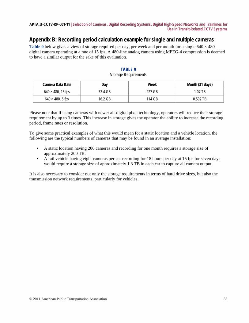
APTA IT-CCTV-RP-001-11 | Selection of Cameras, Digital Recording Systems, Digital High-Speed Networks and Trainlines for Use in Transit-Related CCTV Systems
© 2011 American Public Transportation Association 35
Appendix B: Recording period calculation example for single and multiple cameras Table 9 below gives a view of storage required per day, per week and per month for a single 640 × 480 digital camera operating at a rate of 15 fps. A 480-line analog camera using MPEG-4 compression is deemed to have a similar output for the sake of this evaluation.
TABLE 9 Storage Requirements
Camera Data Rate Day Week Month (31 days)
640 × 480, 15 fps 32.4 GB 227 GB 1.07 TB
640 × 480, 5 fps 16.2 GB 114 GB 0.502 TB
Please note that if using cameras with newer all-digital pixel technology, operators will reduce their storage requirement by up to 3 times. This increase in storage gives the operator the ability to increase the recording period, frame rates or resolution.
To give some practical examples of what this would mean for a static location and a vehicle location, the following are the typical numbers of cameras that may be found in an average installation:
• A static location having 200 cameras and recording for one month requires a storage size of approximately 200 TB.
• A rail vehicle having eight cameras per car recording for 18 hours per day at 15 fps for seven days would require a storage size of approximately 1.3 TB in each car to capture all camera output.
It is also necessary to consider not only the storage requirements in terms of hard drive sizes, but also the transmission network requirements, particularly for vehicles.
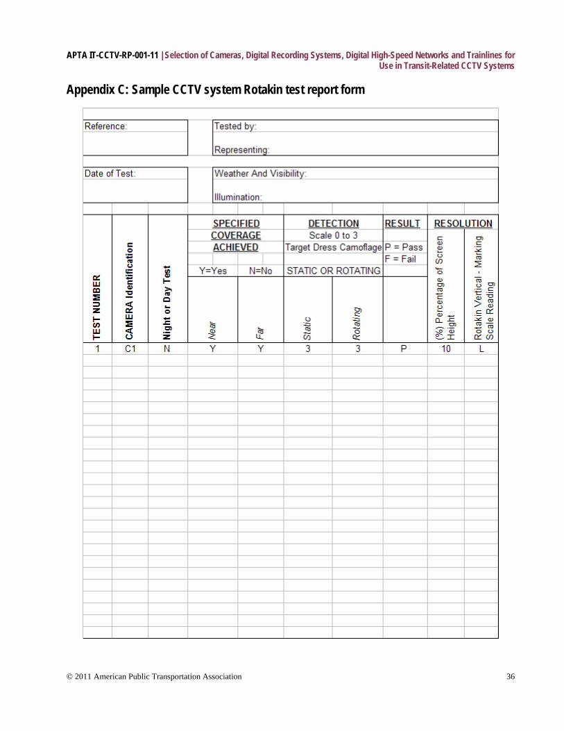
APTA IT-CCTV-RP-001-11 | Selection of Cameras, Digital Recording Systems, Digital High-Speed Networks and Trainlines for Use in Transit-Related CCTV Systems
© 2011 American Public Transportation Association 36
Appendix C: Sample CCTV system Rotakin test report form
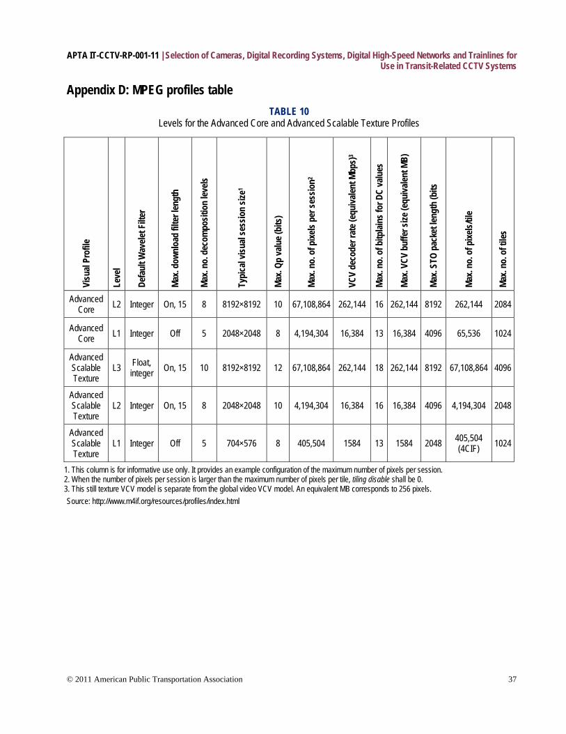
APTA IT-CCTV-RP-001-11 | Selection of Cameras, Digital Recording Systems, Digital High-Speed Networks and Trainlines for Use in Transit-Related CCTV Systems
© 2011 American Public Transportation Association 37
Appendix D: MPEG profiles table
TABLE 10 Levels for the Advanced Core and Advanced Scalable Texture Profiles
Visu
al Pr
ofile
Leve
l
Defa
ult W
avele
t Filt
e r
Max.
down
load
filte
r len
gth
Max.
no. d
ecom
posit
ion
levels
Typi
cal v
isual
sess
ion
size1
Max.
Qp va
lue (
bits
)
Max.
no. o
f pixe
ls pe
r ses
sion2
VCV
deco
der r
ate (
equi
valen
t Mbp
s)3
Max.
no. o
f bitp
lains
for D
C va
lues
Max.
VCV
buffe
r size
(equ
ivalen
t MB)
Max.
STO
pack
et le
ngth
(bits
Max.
no. o
f pixe
ls/til
e
Max.
no. o
f tile
s
Advanced Core L2 Integer On, 15 8 8192×8192 10 67,108,864 262,144 16 262,144 8192 262,144 2084
Advanced Core L1 Integer Off 5 2048×2048 8 4,194,304 16,384 13 16,384 4096 65,536 1024
Advanced Scalable Texture
L3 Float, integer On, 15 10 8192×8192 12 67,108,864 262,144 18 262,144 8192 67,108,864 4096
Advanced Scalable Texture
L2 Integer On, 15 8 2048×2048 10 4,194,304 16,384 16 16,384 4096 4,194,304 2048
Advanced Scalable Texture
L1 Integer Off 5 704×576 8 405,504 1584 13 1584 2048 405,504 (4CIF) 1024
1. This column is for informative use only. It provides an example configuration of the maximum number of pixels per session. 2. When the number of pixels per session is larger than the maximum number of pixels per tile, tiling disable shall be 0. 3. This still texture VCV model is separate from the global video VCV model. An equivalent MB corresponds to 256 pixels. Source: http://www.m4if.org/resources/profiles/index.html
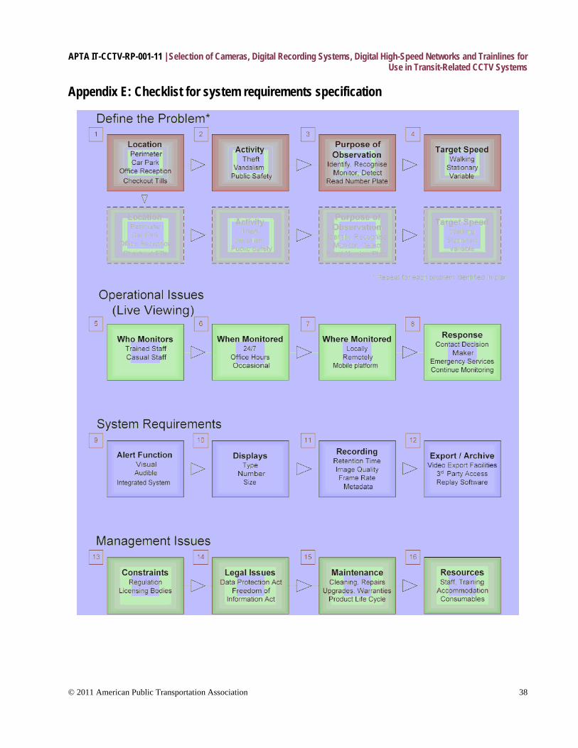
APTA IT-CCTV-RP-001-11 | Selection of Cameras, Digital Recording Systems, Digital High-Speed Networks and Trainlines for Use in Transit-Related CCTV Systems
© 2011 American Public Transportation Association 38
Appendix E: Checklist for system requirements specification

APTA IT-CCTV-RP-001-11 | Selection of Cameras, Digital Recording Systems, Digital High-Speed Networks and Trainlines for Use in Transit-Related CCTV Systems
© 2011 American Public Transportation Association 39
Define the problem The purpose of this section is to collect the information that the system provider will need in order to select suitable cameras and position them appropriately to capture the scene in the required level of detail. Each threat needs to be considered in detail on a location-by-location basis; therefore, this section should be worked through separately for each location.
1. Location: Where on your premises do you wish to monitor? Divide the site plan into specific zones or locations. A location may be either an area where a particular threat exists, or it may be a strategic location away from the threat, but where monitoring would be appropriate because high-quality images of the offender could be obtained, such as a pinch point or doorway for access and egress. Understand lighting conditions: Is there constant illumination, or does the lighting change throughout the day or because of opening and closing of doors? Consider whether there is a need to monitor throughout the site in order to track individuals, and be aware of the location of any blind spots. It is also possible that two or more separate activities require monitoring in a single area, such as a parking lot, warehouse or entrance. Treat each scenario separately when determining your operational requirements. In a parking lot, for instance, you may have two locations: one where vehicles are monitored as they enter and leave to control access and obtain vehicle registration information, and another where they are in the parking bays.
2. Activity: What potential threat or activity do you wish to monitor? Types of activity that are commonly monitored include the following:
• theft/robbery • public safety • flow of passengers/crowds • unauthorized entry • antisocial behavior/vandalism
Obvious examples include theft from vehicles in a car park or identification of people as they approach the reception desk at the entrance to a building. Other less-obvious examples are to monitor the lines in the ticket area or to identify people entering your premises. A combination of activities may require monitoring. For example, the walkway in a station entrance may need observation to monitor crowd flow for public safety and to detect pickpocketing or antisocial behavior.
3. Purpose of the observation: How much detail do you need in the picture? Consider which of the four levels of detail described in Section 2.2 is most appropriate to your requirement. You may wish to:
• Monitor a large area. • Detect individuals approaching a building. • Recognize known individuals at an entrance. • Obtain images that would enable you (or the police) to identify an unfamiliar individual.
A typical fixed camera can be specified to cover a narrow field of view with a high level of detail (for recognition and identification purposes), or a wide field of view at a lower level of detail (for monitoring and detection), but generally not both. Thus, it is important to consider carefully which of these requirements is the most appropriate for each location. There may be more than one purpose for the observation. For example, there may be a requirement to detect theft from vehicles in a parking area, but also to identify the offenders as
APTA IT-CCTV-RP-001-11 | Selection of Cameras, Digital Recording Systems, Digital High-Speed Networks and Trainlines for Use in Transit-Related CCTV Systems
© 2011 American Public Transportation Association 40
they leave. However, the image clarity required for identifying those people would need to be greater than that required to detect an action such as breaking into a vehicle.
4. Target speed: How fast will the target be moving? This information is important to enable a suitable frame rate to be set for recording an event. The event may be monitored in real time, but most CCTV systems record in time-lapse mode to reduce the amount of storage required, with only a certain number of frames per second being stored. A low frame rate may be adequate if monitoring a corridor where little activity takes place (e.g., 5 fps), but a higher frame rate will be necessary if monitoring a busy area or a doorway through which people pass quickly (greater than 15 fps).
Operational issues This covers the day-to-day operation of the system; in other words, who monitors the system, where they are monitoring, and how they should respond in the event of an activity. Most large CCTV installations will have a staffed control room (or OCC) from which events are monitored. Some smaller CCTV installations, however, are designed primarily to record video that can be reviewed in the event of an incident. A screen on which the live view can be displayed usually will be provided as part of the system, but this may not be monitored regularly by the staff. The following section may, therefore, not be applicable for all systems although, as part of the control room development process, thought should nevertheless be given to whether occasional live monitoring may be required.
5. Who monitors: Who will be responsible for monitoring the CCTV screens? The following are the most common options:
• Dedicated personnel whose sole responsibility is to operate the system and respond to events. • Casual operation by personnel (e.g., a ticket agent) as a secondary function to their main role. Some
systems are designed only for recording and post-event investigation, in which case nobody would be required to monitor the activities live. Additionally, consider whether personnel should receive training and, if so, to what level. Does the agency require a license for an operator at the city, state or federal level?
6. When monitored: What hours during the day, and what days of the week is live monitoring required? It may be the case that the control room is staffed during the site’s opening hours, but not at other times, or there may be a requirement for 24-hour monitoring. Similarly, the same regime may be required every day, or a different regime may be appropriate on weekends or at times of higher-than-normal risk, such as after a sports or public event, or during a protest.
7. Where monitored: Where is the CCTV control room located? The first decision is whether the monitoring is performed off-site, perhaps by a specialist third-party non-agency monitoring and response services company, or at the premises. If the monitoring is to be performed on the premises, a suitable location must be identified to accommodate the operators and the core system equipment. Good design of the control room is fundamental to ensuring the effectiveness of your system. The layout should enable the observer to view each camera to the required level of detail.
The following points are worth considering:
• Size and shape of room.
APTA IT-CCTV-RP-001-11 | Selection of Cameras, Digital Recording Systems, Digital High-Speed Networks and Trainlines for Use in Transit-Related CCTV Systems
© 2011 American Public Transportation Association 41
• Light and ventilation. Ensure that the light level is appropriate and that lights are positioned so as not to cause glare on the displays. Also, bear in mind that the equipment may generate significant heat, and additional ventilation or air conditioning units may be required.
• Security (e.g., access control to prevent unauthorized viewing or tampering, with access records kept).
• Proximity to the locations being monitored. • Ergonomics. Is the layout comfortable for the operators and does it allow them to maintain
appropriate levels of alertness? Is a display screen equipment (DSE) assessment required?
8. Response: What happens when an event occurs? Consider who decides when a response is necessary and what that response should be. For example, it might be appropriate for the operator to contact any of the following:
• a guard on patrol • the site manager • the emergency services • the control room of a neighboring CCTV facility
In some cases, it may be appropriate to simply note the event and take no further action. The CCTV control room should be equipped with suitable communication facilities to enable the operator to easily contact the relevant personnel. Estimate an acceptable response time for the activities being monitored, and consider whether the operator should be instructed to continue monitoring the subject until the response arrives.
EXAMPLE: While monitoring the reception area, an operator identifies a person drunkenly stumbling toward the desk. His response would be to call the security guard to escort the unwanted visitor from the premises. He would then contact the receptionist and confirm that he was aware of the situation and advise that a guard would attend.
EXAMPLE: Two suspects are spotted in a parking garage attempting to gain entry to a vehicle. The operator’s response would be to call transit security to intercept the suspects and then contact the transit or local police to report the crime.
System requirements 9. Alert function (video analytics): What action should the system take when an event is detected? Many systems have some configurable automatic alert function that is activated when a particular event occurs. It may be desirable to integrate the CCTV with other protective security equipment, such as an intruder detection system, which will detect an event such as the opening of a door and then activate the CCTV. Alternatively, the event may be detected by the CCTV system itself, if it has built-in video motion detection (VMD) capability or more advanced video-based detection system (VBDS) capability, also known as “intelligent video.” A decision should be made regarding what type of activity should trigger an alert and then what form that alert should take:
• A simple audible alarm, such as a beep. • A visual alarm, such as a flashing light that pinpoints the location of the event on a plan of the facility
on a screen in front of the operator. • A text message or an image sent to a key holder. • An emergency relay sent to the local or transit police. • Recording of event data. Some systems do not record continuously, but only when motion is detected.
This often is done to reduce the storage requirement. However, this feature should be used with
APTA IT-CCTV-RP-001-11 | Selection of Cameras, Digital Recording Systems, Digital High-Speed Networks and Trainlines for Use in Transit-Related CCTV Systems
© 2011 American Public Transportation Association 42
caution, because false triggers such as flickering lights may cause continuous activation, which will fill the hard drive more rapidly than expected. If alarm-activated recording is used, it could be desirable to be able to start the recording at a point several seconds before the actual event occurs, so that the lead-up to the event can be seen. This would require a record buffer, or short-term storage of all video, which is automatically overwritten unless an event is detected. An alternative scenario is that all video is recorded at a high frame rate, and then some frames from the less significant sections are deleted after a set time.
• A display that appears on a monitor screen in front of the operator. It may be advisable for some monitor screens in the control room to remain blank under normal conditions and be activated only when an event is detected.
• The creation of a record of the event in an audit log.
EXAMPLE: A person enters a corridor leading to a secure storage room. The corridor is not normally accessed, so it is not subject to continuous monitoring or recording. However, when the person is detected, the recorder is activated and an alarm sent to the control room operator.
10. Display: How will the images be viewed? If live monitoring is required, the following points need to be considered:
• The number of screens required depends on the number of cameras but is also a balance between the number of operators and how many displays they can effectively monitor at any one time. It has been suggested that a single operator should monitor no more than 10 screens simultaneously, although this figure may need to be reduced when the screens show high levels of activity or detail that need careful monitoring. Some camera views may require constant monitoring and will need a dedicated screen. Others may not, in which case a single screen could be used to cycle among several cameras. Separate displays or a separate viewing area may be required for reviewing recorded video.
• The number of cameras per display screen will depend primarily on the activities you wish to detect and on the display’s size. It may be the case that one display is split to show the view of several cameras, although this will reduce the resolution and effective screen height of the target (e.g., change “detect” to “monitor,” as discussed in Section 2.2) and may not be suitable if the view is of particular importance or the scene is complex. A standard size screen should display no more than four cameras. Another option would be for a given screen to display the views of several cameras in a regular sequence. Displays are getting larger and costs are getting lower, so size will partly be a financial decision and partly be dependent on the space available. Be aware, however, that having one big screen in the place of a few smaller ones can reduce the flexibility of the viewing system.
• The type of display is a choice between traditional CRT screens and more modern LCD or plasma displays. See Section 3.10.
11. Recording: How long is the video retained on the system before being overwritten? What image quality is required on the recorded image compared with the live image? What frame rate is required for the recorded video? What additional information should be recorded with the video? Most new CCTV systems rely on digital recording technology, in which the video data is recorded onto a hard drive like that found on a standard computer. The drive has a finite storage capacity, so a digital CCTV recorder operating continuously can retain video on the system only for a set period before it is overwritten. A retention time of 31 days has traditionally been recommended for most CCTV applications, as this provides sufficient time for the authorities to attend the scene and retrieve the video in the event of a serious incident.
However, consider that data should not be retained for longer than necessary. The CCTV manager should make a decision on a suitable retention time for his or her application. Some systems offer the additional
APTA IT-CCTV-RP-001-11 | Selection of Cameras, Digital Recording Systems, Digital High-Speed Networks and Trainlines for Use in Transit-Related CCTV Systems
© 2011 American Public Transportation Association 43
facility of protecting sequences of particular interest to prevent them from being overwritten. When a digital video recorder saves images, it compresses them so that more data can be saved on the hard drives. This compression will almost invariably reduce the quality of the video. When specifying a CCTV recorder, it is, therefore, vital to inspect the quality of the recorded images as well as the live view as there could be a substantial difference between the two.
Adjusting the recorder settings to increase the retention time will result in a reduction in the stored image quality (i.e., “Best Storage” settings give you the lowest-quality recorded video). Cameras with all digital pixel technology produce video output that is more efficiently compressed than cameras with analog CCD-based technology. Choose cameras appropriate for the application only after a careful evaluation has been performed that includes compression efficiency as one of the key factors.
Choose an appropriate frame rate for each camera to record, based on speed of motion, etc. Different frame rates may be required at different locations. The operational requirements for the system should specify the required retention time, recorded image quality, and frame rate for each camera. The CCTV supplier will use this information to determine the appropriate storage capacity (hard drive size).
Finally, decide whether additional metadata (text information) should be recorded alongside the video images. A key requirement is to include the time and date information, first, to add evidential weight to the pictures and, second, to allow the user to search through the recordings and retrieve the relevant video efficiently. Provision should also be made for digital signatures and/or computer hashing to further validate recordings for legal purposes. Often there is also a requirement to record the camera location and number. There should be a mechanism for ensuring that the time and date information remains accurate (for example, during the change to and from daylight saving time) and does not slowly drift from the true value. This mechanism can be either technical (such as the inclusion of a clock source automatically linked to the NIST time signal) or procedural (instructions to the operator to check and update the clock regularly). Should the recorded data be of critical importance, it might be worthwhile to take additional measures to protect the recording system against the possibility of hard drive failure. This is usually achieved by specifying a RAID recording system. There are several RAID standards, but they commonly involve splitting/duplicating the data across more than one hard drive.
12. Export/archive: How will you export data to create a permanent record? Who will require access to the data? How will they replay the video? A CCTV recorder should provide a means of creating a permanent record of an incident, which can be provided as evidence for any subsequent investigation. With an analog recorder, the process is straightforward, as the relevant videocassette can be removed and retained. For a digital recorder, however, the incident must be copied from the internal hard drive to a permanent storage medium such as a CD/DVD before it is overwritten. The CCTV system, therefore, needs to be provided with a suitable export facility. In most cases, a CD or DVD writer will suffice for exporting single images and short video clips under about 10 minutes in length. For exporting longer video clips and for large-scale archiving, the system should provide one of the following:
• the ability to export video to an external plug-and-play hard drive via a USB or a fire wire connection • a network port • a removable hard drive
Note that network and USB ports can operate at a range of speeds, the slower of which may not be suitable for transferring large volumes of data. The latest (and fastest) standard should be specified for a new system.
APTA IT-CCTV-RP-001-11 | Selection of Cameras, Digital Recording Systems, Digital High-Speed Networks and Trainlines for Use in Transit-Related CCTV Systems
© 2011 American Public Transportation Association 44
There may be a requirement for a system to be permanently connected to a network, to provide remote access either for data downloads or for live viewing, and possibly to provide a link to other CCTV systems as part of a larger CCTV network. The exported video sequence may be in a non-standard format. If this is the case, it is important to ensure that the manufacturers provide additional software so that the video can be replayed and viewed on a standard computer. Many systems enable the replay software to be downloaded from the system at the same time as the data. If a removable hard drive is provided, then this should either be in a format that can be read on a standard computer (Windows-based, Linux-based, etc.) or a separate replay machine should be provided, to which the drive can be attached. The video should be exported in its native file format (i.e., without converting between formats) to maintain image quality, and no additional compression should be applied during the export process.
Management Issues This section covers legal issues as well as resource requirements and the need for ongoing support and maintenance.
13. Constraints: What licensing regulations apply to the CCTV system? This covers any rules or regulations applied by local or central government, such as planning constraints, licensing or public safety provisions. Additional conditions regarding CCTV provisions could be applied by insurance companies, or by any specialist regulatory authorities at the city, state or federal level. The views of these bodies should be sought as part of the stakeholder consultation process. Increasingly, CCTV operators are required to be licensed, especially when monitoring public places.
14. Legal issues: What laws apply to the storage of and access to information? The Data Protection Act in the UK is designed to prevent the misuse of personal information. Legal obligations are placed on anybody who handles this type of information.
The Freedom of Information Act provides a right of access to any recorded information held by public authorities. Legal obligations are placed on public authorities to follow certain procedures when responding to requests for information.
Other state and federal legislation of which to be aware:
• The Human Rights Acts • Regulation of Investigatory Powers Acts, etc.
CCTV operators should be aware of the requirements placed on them by these various laws and should have procedures in place to enable compliance. Note that laws can be amended, new ones introduced and old ones superseded, so it is recommended to seek up-to-date advice.
15. Maintenance: What regular maintenance is required? Who is responsible for ongoing maintenance tasks? Without ongoing maintenance, systems will deteriorate. It should be decided who has responsibility for each of the following activities:
• cleaning the equipment (in particular, cleaning the camera housings) • repairing or replacing faulty equipment (an acceptable turnaround time from report to repair should
be specified in any service contract)
APTA IT-CCTV-RP-001-11 | Selection of Cameras, Digital Recording Systems, Digital High-Speed Networks and Trainlines for Use in Transit-Related CCTV Systems
© 2011 American Public Transportation Association 45
References American Public Transportation Association, “CCTV Placement Standard for Transit Applications,”
document APTA S-FS 002-07, June 2007.
American Public Transportation Association, “Recommended Practice for 27-Point Control and Communication Trainlines for Locomotives and Locomotive-Hauled Equipment,” document APTA RP-E-017-99, June 2006.
Council of Australia Governments, “National Code of Practice for CCTV Systems for Mass Passenger Transport Sector for Counter Terrorism,” 2006.
IEEE Standards Association, IEEE 1473, T, L and E, “IEEE Draft Standard for Communications Protocol Aboard Passenger Trains,” 2002.
IHS, “Surveillance Systems for Use in Security Applications Guidelines,” document BSI EN 50132-7 CCTV, January 1996.
International Organisation for Standardation, “Coding of Moving Pictures and Audio,” document ISO/IEC/JTC1/SC29 WG11, July 2000.
Merseyside Police (UK), “CCTV Systems: Operational Requirement Analysis,” June 2005.
Scientific Working Group, Imaging Technology (SWGIT), “Guidelines for the Use of Imaging Technologies in the Criminal Justice System,” Version 2.1 2004.07.22.
UK Police Scientific Development Branch, “Digital Imaging Procedure,” March 2002.
Definitions 2CIF: For PAL video, 2CIF is 704 × 288 pixels; for NTSC video, 2CIF is 704 × 240 pixels.
4CIF: For PAL video, 4CIF is 704 × 576 pixels; for NTSC video, 4CIF is 704 × 480 pixels.
B-frames: In older standard designs, such as MPEG-2, B pictures are never used as references for the prediction of other pictures. Older standard designs use exactly two previously decoded pictures as references during decoding, require one of those pictures to precede the B picture in display order and the other one to follow it, and typically require fewer bits for encoding than do either I or P pictures.
Category 5 (CAT5): Cable that includes four twisted pairs in a single cable jacket. This use of balanced lines helps preserve a high signal-to-noise ratio despite interference from both external sources and other pairs. (This latter form of interference is called cross talk.) It is most commonly used for 100 Mbps networks, such as 100 base-TX Ethernet.
CIF (Common Intermediate Format): Pixel resolution of a video image. For phase operating line (PAL) video, CIF is 352 × 288 pixels; for National Television Standards Committee (NTSC) video, CIF is 352 × 240 pixels.
codec: A device or program capable of performing encoding and decoding on a digital data stream or signal. The word “codec” may be a combination of any of the following: “compressor-decompressor,” “coder-decoder,” or “compression/decompression algorithm.”
APTA IT-CCTV-RP-001-11 | Selection of Cameras, Digital Recording Systems, Digital High-Speed Networks and Trainlines for Use in Transit-Related CCTV Systems
© 2011 American Public Transportation Association 46
field: In interlaced video, in which a frame consists of two fields, the “top field” is the odd-numbered rows, and the “bottom field” is the even-numbered rows. The two fields are displayed alternately, and two successive fields are called a frame.
field of view (FOV): The area of a scene, observed by a camera and lens combination and measured both horizontally and vertically, that can be seen through the camera. Differing lenses can be configured for wide-angle FOV or narrow FOV, depending on the requirements and whether field of view is measured as a ratio of the minimum and maximum ranges of the FOV in either degrees (angular) or millimeters (linear).
frame: One of the many still images that compose a complete moving picture in film, video production, animation and related fields.
I-frames: I-frames are used for random access and as references for the decoding of other pictures. Intra-refresh periods of one-half second are common on applications such as digital television broadcast and DVD storage.
P-frames: Older standard designs (such as MPEG-2) use only one previously decoded picture as a reference during decoding and require that picture to also precede the P picture in display order. However, H.264 uses multiple previously decoded pictures as references during decoding, can have any arbitrary display-order relationship relative to the picture(s) used for its prediction and typically requires fewer bits for encoding than do I pictures.
pixel: A single point in a graphic image. “Pixel” is short for “picture element,” using the common abbreviation “pix” for “picture.”
public key infrastructure (PKI): A framework for creating a secure method for exchanging information based on public key cryptography. The foundation of a PKI is the certificate authority (CA), which issues digital certificates that authenticate the identity of organizations and individuals over a public system such as the Internet.
Rotakin: A performance test target for CCTV systems developed by the UK Police Scientific Development Board. Also known as Rotatest, it evaluates system-level performance and resolution capabilities, including playback and recordings, end-to-end.
Abbreviations and acronyms AC alternating current APTA American Public Transportation Association ATSC Advanced Television Systems Committee AVI Audio/Video Interleaved AVS analytical video system BALUN balanced-unbalanced BER bit error rate BMP bitmap (file type) BW bandwidth CA certificate authority CCD charge-coupled device CCTV closed-circuit television CD compact disc CIF Common Intermediate Format
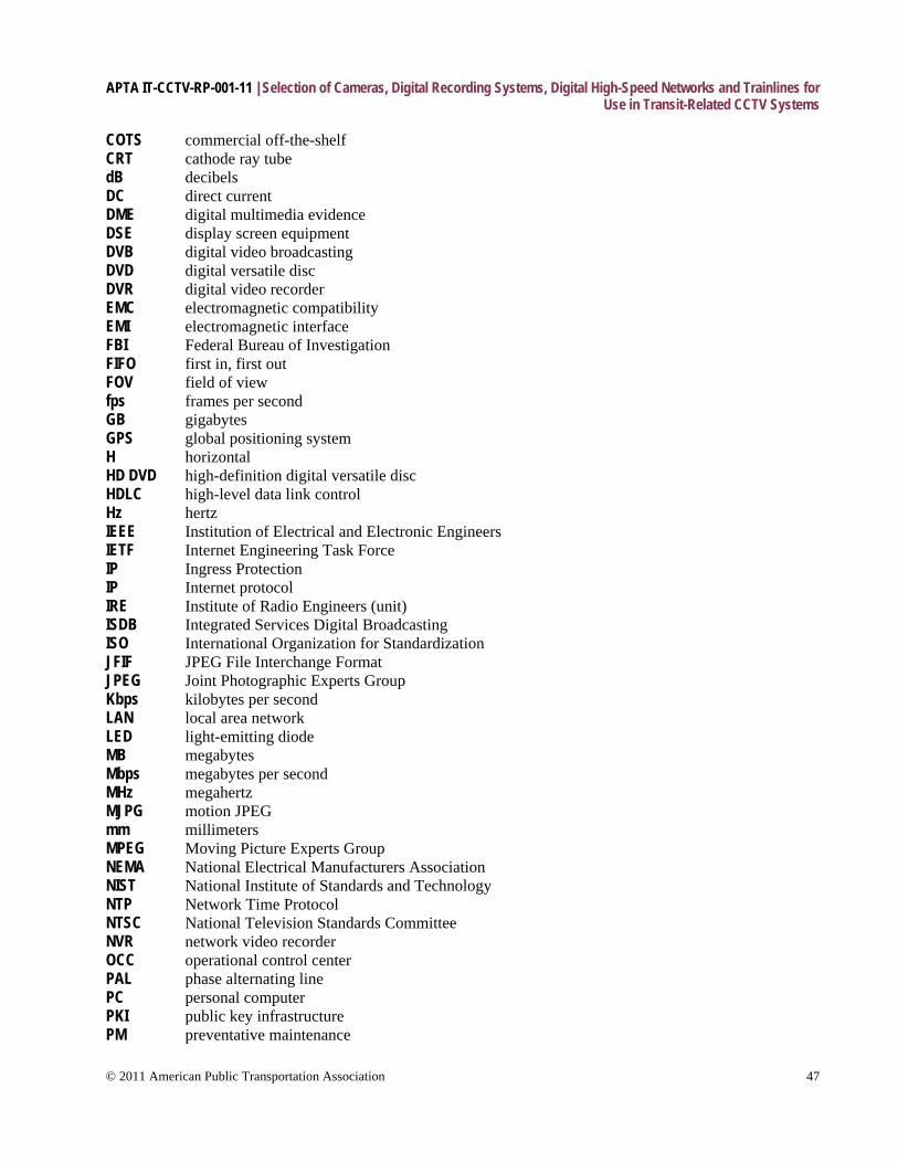
APTA IT-CCTV-RP-001-11 | Selection of Cameras, Digital Recording Systems, Digital High-Speed Networks and Trainlines for Use in Transit-Related CCTV Systems
© 2011 American Public Transportation Association 47
COTS commercial off-the-shelf CRT cathode ray tube dB decibels DC direct current DME digital multimedia evidence DSE display screen equipment DVB digital video broadcasting DVD digital versatile disc DVR digital video recorder EMC electromagnetic compatibility EMI electromagnetic interface FBI Federal Bureau of Investigation FIFO first in, first out FOV field of view fps frames per second GB gigabytes GPS global positioning system H horizontal HD DVD high-definition digital versatile disc HDLC high-level data link control Hz hertz IEEE Institution of Electrical and Electronic Engineers IETF Internet Engineering Task Force IP Ingress Protection IP Internet protocol IRE Institute of Radio Engineers (unit) ISDB Integrated Services Digital Broadcasting ISO International Organization for Standardization JFIF JPEG File Interchange Format JPEG Joint Photographic Experts Group Kbps kilobytes per second LAN local area network LED light-emitting diode MB megabytes Mbps megabytes per second MHz megahertz MJPG motion JPEG mm millimeters MPEG Moving Picture Experts Group NEMA National Electrical Manufacturers Association NIST National Institute of Standards and Technology NTP Network Time Protocol NTSC National Television Standards Committee NVR network video recorder OCC operational control center PAL phase alternating line PC personal computer PKI public key infrastructure PM preventative maintenance
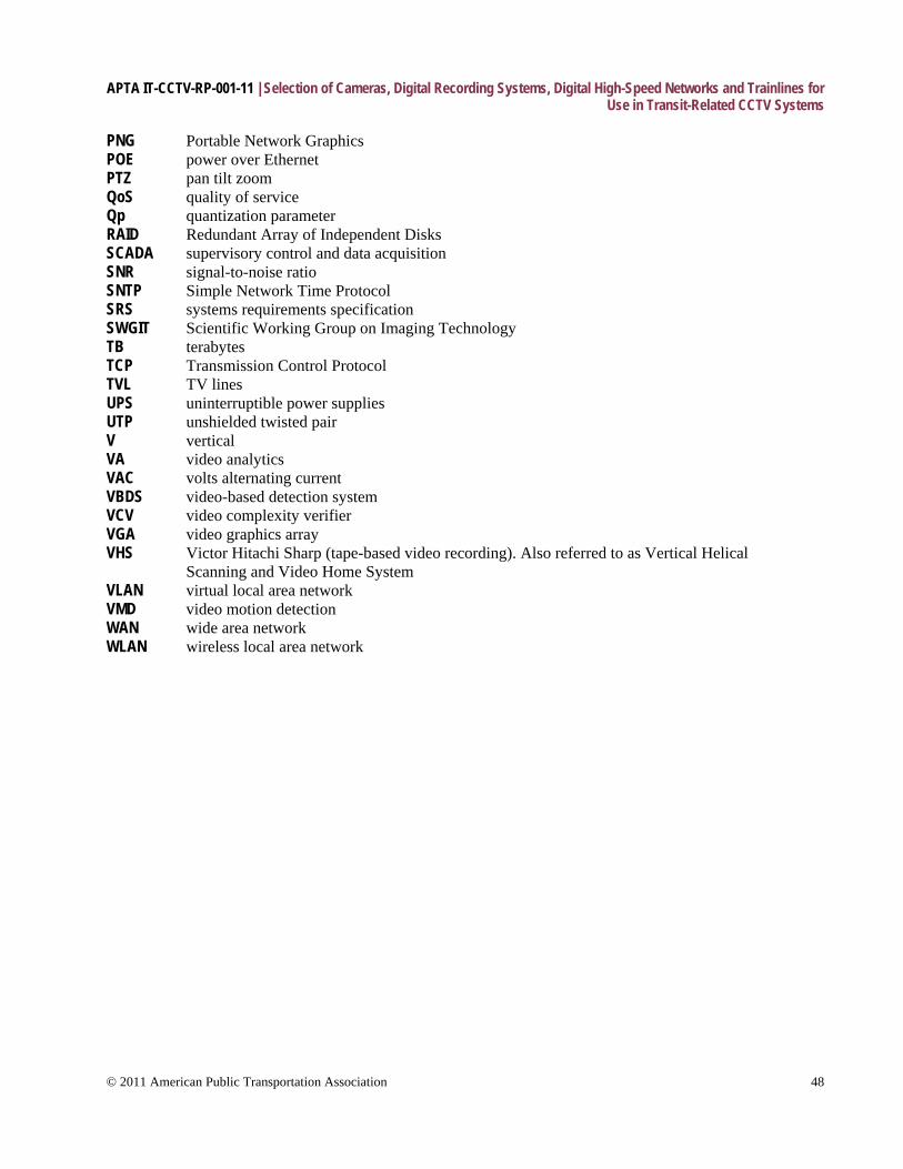
APTA IT-CCTV-RP-001-11 | Selection of Cameras, Digital Recording Systems, Digital High-Speed Networks and Trainlines for Use in Transit-Related CCTV Systems
© 2011 American Public Transportation Association 48
PNG Portable Network Graphics POE power over Ethernet PTZ pan tilt zoom QoS quality of service Qp quantization parameter RAID Redundant Array of Independent Disks SCADA supervisory control and data acquisition SNR signal-to-noise ratio SNTP Simple Network Time Protocol SRS systems requirements specification SWGIT Scientific Working Group on Imaging Technology TB terabytes TCP Transmission Control Protocol TVL TV lines UPS uninterruptible power supplies UTP unshielded twisted pair V vertical VA video analytics VAC volts alternating current VBDS video-based detection system VCV video complexity verifier VGA video graphics array VHS Victor Hitachi Sharp (tape-based video recording). Also referred to as Vertical Helical Scanning and Video Home System VLAN virtual local area network VMD video motion detection WAN wide area network WLAN wireless local area network