Selection and Sizing of Pressure Relief Valves and Sizing of Pressure Relief Valves.pdfFeb 24, 1992...
22
PDHonline Course M112 (3 PDH) 2012 Instructor: Randall W. Whitesides, PE PDH Online | PDH Center 5272 Meadow Estates Drive Fairfax, VA 22030-6658 Phone & Fax: 703-988-0088 www.PDHonline.org www.PDHcenter.com An Approved Continuing Education Provider Selection and Sizing of Pressure Relief Valves
Transcript of Selection and Sizing of Pressure Relief Valves and Sizing of Pressure Relief Valves.pdfFeb 24, 1992...

PDHonline Course M112 (3 PDH)
2012
Instructor: Randall W. Whitesides, PE
PDH Online | PDH Center5272 Meadow Estates Drive
Fairfax, VA 22030-6658Phone & Fax: 703-988-0088
www.PDHonline.orgwww.PDHcenter.com
An Approved Continuing Education Provider
Selection and Sizing of Pressure Relief Valves

SELECTION AND SIZING OF PRESSURE RELIEF VALVES
Randall W. Whitesides, P.E.
GENERAL/SCOPE/INTRODUCTION
IntroductionThe function of a pressure relief valve is to protect pressure vessels, piping systems, and other equipmentfrom pressures exceeding their design pressure by more that a fixed predetermined amount. Thepermissible amount of overpressure is covered by various codes and is a function of the type ofequipment and the conditions causing the overpressure.
It is not the purpose of a pressure relief valve to control or regulate the pressure in the vessel or systemthat the valve protects, and it does not take the place of a control or regulating valve.
The aim of safety systems in processing plants is to prevent damage to equipment, avoid injury topersonnel and to eliminate any risks of compromising the welfare of the community at large and theenvironment. Proper sizing, selection, manufacture, assembly, test, installation, and maintenance of apressure relief valve are critical to obtaining maximum protection.
Types, Design, and ConstructionA pressure relief valve must be capable of operating at all times, especially during a period of powerfailure; therefore, the sole source of power for the pressure relief valve is the process fluid.
The pressure relief valve must open at a predetermined set pressure, flow a rated capacity at a specifiedoverpressure, and close when the system pressure has returned to a safe level. Pressure relief valves mustbe designed with materials compatible with many process fluids from simple air and water to the mostcorrosive media. They must also be designed to operate in a consistently smooth manner on a variety offluids and fluid phases. These design parameters lead to the wide array of pressure relief valve productsavailable in the market today.
Note: For ease of learning, the student isencouraged to print the glossary and refer tothe definitions of words or phrases as theyfirst appear while studying the coursematerial.
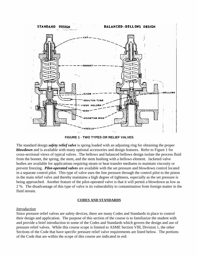
FIGURE 1 - TWO TYPES OR RELIEF VALVES
The standard design safety relief valve is spring loaded with an adjusting ring for obtaining the properblowdown and is available with many optional accessories and design features. Refer to Figure 1 forcross-sectional views of typical valves. The bellows and balanced bellows design isolate the process fluidfrom the bonnet, the spring, the stem, and the stem bushing with a bellows element. Jacketed valvebodies are available for applications requiring steam or heat transfer mediums to maintain viscosity orprevent freezing. Pilot-operated valves are available with the set pressure and blowdown control locatedin a separate control pilot. This type of valve uses the line pressure through the control pilot to the pistonin the main relief valve and thereby maintains a high degree of tightness, especially as the set pressure isbeing approached. Another feature of the pilot-operated valve is that it will permit a blowdown as low as2 %. The disadvantage of this type of valve is its vulnerability to contamination from foreign matter in thefluid stream.
CODES AND STANDARDS
IntroductionSince pressure relief valves are safety devices, there are many Codes and Standards in place to controltheir design and application. The purpose of this section of the course is to familiarize the student withand provide a brief introduction to some of the Codes and Standards which govern the design and use ofpressure relief valves. While this course scope is limited to ASME Section VIII, Division 1, the otherSections of the Code that have specific pressure relief valve requirements are listed below. The portionsof the Code that are within the scope of this course are indicated in red:

List of Code Sections Pertaining to Pressure Relief Valves
Section I Power BoilersSection III, Division 1 Nuclear Power Plant ComponentsSection IV Heating BoilersSection VI Recommended Rules for the Care and Operation of Heating BoilersSection VII Recommended Rules for the Care of Power BoilersSection VIII, Division 1 Pressure Vessels
Appendix 11 Capacity Conversions for Safety ValvesAppendix M Installation and Operation
Section VIII, Division 2 Pressure Vessels - Alternative RulesB31.3, Chapter II, Part 3 Power Piping - Safety and Relief ValvesB31.3, Chapter II, Part 6 Power Piping - Pressure Relief Piping
ASME specifically states in Section VIII, Division 1, paragraph UG-125 (a) “All pressure vessels withinthe scope of this division, irrespective of size or pressure, shall be provided with pressure relief devices inaccordance with the requirements of UG-125 through UG-137.”
Reference is made to the ASME Boiler and Pressure Vessel Code, Section VIII, Division 1. Theinformation in this course is NOT to be used for the application of overpressure protection to powerboilers and nuclear power plant components that are addressed in the Code in Section I and Section IIIrespectively. The student should understand that the standards listed here are not all inclusive and thatthere exists specific standards for the storage of chlorine, ammonia, compressed gas cylinders, and theoperation of refrigeration units, among probable others.
A Brief History of the ASME CodeMany states began to enact rules and regulations regarding the construction of steam boilers and pressurevessels following several catastrophic accidents that occurred at the turn of the twentieth century thatresulted in large loss of life. By 1911 it was apparent to manufacturers and users of boilers and pressurevessels that the lack of uniformity in these regulations between states made it difficult to construct vesselsfor interstate commerce. A group of these interested parties appealed to the Council of the AmericanSociety of Mechanical Engineers to assist in the formulation of standard specifications for steam boilersand pressure vessels. (The American Society of Mechanical Engineers was organized in 1880 as aneducational and technical society of Mechanical Engineers). After years of development and publiccomment the first edition of the code, ASME Rules of Construction of Stationary Boilers and forAllowable Working Pressures, was published in 1914 and formally adopted in the spring of 1915. Fromthis simple beginning the code has now evolved into the present eleven section document, with multiplesubdivisions, parts, subsections, and mandatory and non-mandatory appendices.
The ASME Code Symbol Stamp and the letters “UV” on a pressure relief valve indicate that the valve hasbeen manufactured in accordance with a controlled quality assurance program, and that the relievingcapacity has been certified by a designated agency, such as the National Board of Boiler and PressureVessel Inspectors.

Adoption of the ASME Code by the StatesAs of this writing, all states of the United States, with the exception of South Carolina, have adopted theASME Code as jurisdictional law. The student should consult with local regulatory authorities, e.g. stateagencies, to determine any specialized jurisdictional requirements for pressure relief valves that may beapplicable.
EQUATION NOMENCLATURE
Unless otherwise noted, all symbols used in this course are defined as follows:
A = Valve effective orifice area, in².
C = Flow constant determined by the ratio of specific heats, see Table 2 (use C = 315 if k is unknown)
G = Specific gravity referred to water = 1.0 at 70°F
K = Coefficient of discharge obtainable from valve manufacture (K = 0.975 for many nozzle-type valves)
Kb = Correction factor due to back pressure. This is valve specific; refer to manufacturer’s literature.
Kn = Correction factor for saturated steam at set pressures > 1,500 psia, see Equation 6
Kp = Correction factor for relieving capacity vs. lift for relief valves in liquid service, see Equations 1 & 2
Ksh = Correction factor due to the degree of superheat in steam (Ksh = 1.0 for saturated steam)
Kv = Correction factor for viscosity, see Equations 8 & 9 (use Kv =1.0 for all but highly viscous liquids)
Kw = Correction factor due to back pressure for use with balanced bellows valves
M = Molecular weight, see Table 2 for values of some common gases
P1 = Upstream pressure, psia (set pressure + overpressure + atmospheric pressure)
!!!!P = Differential pressure (set pressure, psig ! back pressure, psig)
Q = Flow, gpm
T = Inlet vapor temperature, °R
Rne = Reynolds numbers,
W = Flow, lb/hr
Z = Compressibility factor (use Z = 1 for ideal gas)
"""" = Liquid dynamic (absolute) viscosity, centipoise

SIZING AND SELECTION
IntroductionPressure relief valves must be selected by those who have complete knowledge of the pressure relievingrequirements of the system to be protected and the environmental conditions particular to that installation.Too often pressure relief valve sizes are determined by merely matching the size of an existing availablevessel nozzle, or the size of an existing pipe line connection.
Correct and comprehensive pressure relief valve sizing is a complex multi-step process that should followthe following stepwise approach:
1. Each piece of equipment in a process should be evaluated for potential overpressure scenarios.2. An appropriate design basis must be established for each vessel. Choosing a design basis requires
assessing alternative scenarios to find the credible worst case scenario.3. The design basis is then used to calculate the required pressure relief valve size. If possible, the sizing
calculations should use the most current methodologies incorporating such considerations as twophase flow and reaction heat sources.
This course addresses pressure relief valves as individual components. Therefore, detailed design aspectspertaining to ancillary piping systems are not covered. These are clearly noted in the course. Thesedesign issues can be addressed by piping analysis using standard accepted engineering principles; theseare not within the scope of this course. Where relief device inlet and outlet piping are subject to importantguidance by the ASME Code, it is so noted.
In order to properly select and size a pressure relief valve, the following information should be ascertainedfor each vessel or group of vessels which may be isolated by control or other valves. The data required toperform pressure relief valve sizing calculations is quite extensive. First, the equipment dimensions andphysical properties must be assembled. Modeling heat flow across the equipment surface requiresknowledge of the vessel material’s heat capacity, thermal conductivity, and density (if vessel mass isdetermined indirectly from vessel dimensions and wall thickness). The vessel geometry – vertical orhorizontal cylinder, spherical, etc. – is a necessary parameter for calculating the wetted surface area, wherethe vessel contents contact vessel walls. Second, the properties of the vessel contents must be quantified. This includes density, heat capacity, viscosity, and thermal conductivity. Values of each parameter arerequired for both liquid and vapor phases. Boiling points, vapor pressure, and thermal expansioncoefficient values also are required. Ideally, the properties will be expressed as functions of temperature,pressure, and compositions of the fluid.
Determination of the Worst-Case Controlling ScenarioAs process plants become larger and are operated closer to safety limits, a systematic approach to safetybecomes a necessity.
The most difficult aspect of the design and sizing of pressure relief valves is ascertaining the controllingcause of overpressure. This is sometimes referred to as the worst case scenario. Overpressure inequipment may result from a number of causes or combination of causes. Each cause must beinvestigated for its magnitude and for the probability if its occurrence with other events. The objectivemight be to document why the particular design basis is the correct choice. The question that will always

remain: which scenario is the credible worst case? Among the techniques available to solve this problemis fault-tree analysis. A fault tree is a graphical representation of the logical connections between basicevents (such as a pipe rupture or the failure of a pump or valve) and resulting events (such as anexplosion, the liberation of toxic chemicals, or over-pressurization in a process tank). A completetreatment of fault-tree theory and analysis is beyond the scope of this course.
The usual causes of overpressure and ways of translating their effects into pressure relief valverequirements are given in the following list. In most cases, the controlling overpressure will be thatresulting from external fire.
1. Heat from external fire 2. Equipment failure 3. Failure of Condenser system 4. Failure of Cooling Medium 5 . Failure of Control system 6. Chemical reactions 7. Entrance of Volatile Fluid 8. Closed Outlets 9. Thermal Expansion of Liquids10. Operating error
Pressure relief valves must have sufficient capacity when fully opened to limit the maximum pressurewithin the vessel to 110% of the maximum allowable working pressure (MAWP). This incrementalpressure increase is called the pressure accumulation. However, if the overpressure is caused by fire ofother external heat, the accumulation must not exceed 21% of the MAWP.
Section VIII does not outline a detailed method to determine required relieving capacity in the case ofexternal fire. Appendix M-14 of the Code recommends that the methods outlined in Reference 3 beemployed. The student is directed to Reference 7 for an excellent treatment, including examples, of themethodology of API Recommended Practice 520 (Reference 3).
Determination of Set Point PressureProcess equipment should be designed for pressures sufficiently higher than the actual working pressure toallow for pressure fluctuations and normal operating pressure peaks. In order that process equipment isnot damaged or ruptured by pressures in excess of the design pressure, pressure relief valves are installedto protect the equipment. The design pressure of a pressure vessel is the value obtained after adding amargin to the most severe pressure expected during the normal operation at a coincident temperature. Depending on the situation, this margin might typically be the maximum of 25 psig or 10%.
The set point of a pressure relief valve is typically determined by the MAWP. The set point of the reliefdevice should be set at or below this point. When the pressure relief valve to be used has a set pressurebelow 30 psig, the ASME Code specifies a maximum allowable overpressure of 3 psi.
Pressure relief valves must start to open at or below the maximum allowable working pressure of theequipment. When multiple pressure relief valves are used in parallel, one valve should be set at or belowthe MAWP and the remaining valve(s) may be set up to 5% over the MAWP. When sizing for multiplevalve applications, the total required relief area is calculated on an overpressure of 16% or 4 psi,whichever is greater.
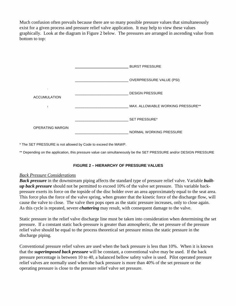
Much confusion often prevails because there are so many possible pressure values that simultaneouslyexist for a given process and pressure relief valve application. It may help to view these valuesgraphically. Look at the diagram in Figure 2 below. The pressures are arranged in ascending value frombottom to top:
_______________________ BURST PRESSURE
_________________________ OVERPRESSURE VALUE (PSI)
!_________________________ DESIGN PRESSURE
ACCUMULATION
"""" _________________________ MAX. ALLOWABLE WORKING PRESSURE**
_________________________ SET PRESSURE*
OPERATING MARGIN_________________________ NORMAL WORKING PRESSURE
* The SET PRESSURE is not allowed by Code to exceed the MAWP.
** Depending on the application, this pressure value can simultaneously be the SET PRESSURE and/or DESIGN PRESSURE
FIGURE 2 – HIERARCHY OF PRESSURE VALUES
Back Pressure ConsiderationsBack pressure in the downstream piping affects the standard type of pressure relief valve. Variable built-up back pressure should not be permitted to exceed 10% of the valve set pressure. This variable back-pressure exerts its force on the topside of the disc holder over an area approximately equal to the seat area. This force plus the force of the valve spring, when greater that the kinetic force of the discharge flow, willcause the valve to close. The valve then pops open as the static pressure increases, only to close again. As this cycle is repeated, severe chattering may result, with consequent damage to the valve.
Static pressure in the relief valve discharge line must be taken into consideration when determining the setpressure. If a constant static back-pressure is greater than atmospheric, the set pressure of the pressurerelief valve should be equal to the process theoretical set pressure minus the static pressure in thedischarge piping.
Conventional pressure relief valves are used when the back pressure is less than 10%. When it is knownthat the superimposed back pressure will be constant, a conventional valve may be used. If the backpressure percentage is between 10 to 40, a balanced bellow safety valve is used. Pilot operated pressurerelief valves are normally used when the back pressure is more than 40% of the set pressure or theoperating pressure is close to the pressure relief valve set pressure.
If back pressure on valves in gas and vapor service exceeds the critical pressure (generally taken as 55%of accumulated inlet pressure, absolute), the flow correction factor Kb must be applied. If the backpressure is less than critical pressure, no correction factor is generally required.
Overpressure ConsiderationsBack pressure correction factors should not be confused with the correction factor Kp that accounts for thevariation in relieving capacity of relief valves in liquid service that occurs with the change in the amountof overpressure or accumulation. Typical values of Kp range from 0.3 for an overpressure of 0%, 1.0 for25%, and up to 1.1 for an overpressure of 50%. A regression analysis on a typical manufacturer’sperformance data produced the following correlation equations for Kp:
For % overpressure < 25,
(1)K overpressure overpressurep = − + +0 0014 0 073 0 0162. (% ) . (% ) .
For 25 " % overpressure < 50,
(2)K overpressurep = +0 00335 0 918. (% ) .
Determination of Effective Orifice AreaOnce the pressure and rate of relief have been established for a particular vessel or pipeline, the requiredsize of the pressure relief valve orifice, or the effective area, can be determined. Sizing formulae in thiscourse can be used to calculate the required effective area of a pressure relief valve that will flow therequired volume of system fluid at anticipated relieving conditions. The appropriate valve size and stylemay then be selected having an actual discharge area equal to or greater that the calculated requiredeffective area. The industry has standardized on valve orifice sizes and has identified them with lettersfrom D through T having areas of 0.110 in2 through 26.0 in2 respectively. The standard nozzle orificedesignations and their corresponding discharge areas are given in Table 1.

NOZZLE ORIFICE AREAS
Size Designation Orifice Area, in2
D 0.110
E 0.196
F 0.307
G 0.503
H 0.785
J 1.280
K 1.840
L 2.850
M 3.600
N 4.340
P 6.380
Q 11.050
R 16.000
T 26.000
TABLE 1 – STANDARD NOZZLE ORIFICE DATA
There are a number of alternative methods to arrive at the proper size. If the process fluid application issteam, air, or water and the pressure relief valve discharges to atmosphere, manufacturer’s literature canbe consulted. These publications contain capacity tables for the manufacturer’s various valves for thefluids just mentioned at listed set pressures plus several overpressure values. Given the large quantity oftables usually presented, caution must be exercised to use the proper table. With careful consideration, thetables’ usefulness can be expanded by making the proper adjustments via correction factors for specificheat ratio, temperature, molecular weight, specific gravity, inlet and outlet piping frictional pressurelosses, and fluid viscosity. This extrapolation of the standard tables is not recommended by this writer.
EXAMPLE 1 (Steam Application)
Given:Fluid: Saturated steamRequired Capacity: 40,000 lb/hrSet Pressure: 140 psigOverpressure: 10% (or 14 psig)Back Pressure: AtmosphericInlet relieving Temperature: Saturation temperatureMolecular Weight: 18
Find: XYZ Valve Company’s standard orifice for this application.
Solution: Refer to Figure 3 and find that a “P” orifice is required, which will have a capacity of 53,820 lb/hr.

THE XYZ VALVE COMPANYApproved: API-ASME and ASME Certified: National Board of Boiler Pressure Vessel Codes and Pressure Vessel Inspectors
Capacity in Pounds per Hour of Saturated Steam at Set Pressure Plus 10% Overpressure
SetPress(psig)
O R I F I C E D E S I G N A T I O N
D E F G H J K L M N P Q R T
10 141 252 395 646 1009 165 10 3666 4626 5577 8198 14200 20550 33410
20 202 360 563 923 1440 2362 3373 5235 6606 7964 11710 20280 29350 47710
30 262 467 732 1200 1872 3069 4384 6804 8586 10350 15220 26350 38200 62010
40 323 575 901 1476 2304 3777 5395 8374 10570 12740 18730 32430 47000 76310
50 383 683 1070 1753 2736 4485 6405 9943 12550 15120 22230 38510 55800 90610
60 444 791 1939 9030 3167 5193 7416 11510 14530 17510 25740 44590 64550 104900
70 504 899 1408 2306 3599 5901 8427 13080 16510 19900 29250 50660 73400 119200
80 565 1005 1576 2583 4031 6609 9438 14650 18490 22290 32760 56740 82100 133500
90 625 1115 1745 2860 4463 7317 10450 16220 20470 24670 36270 69890 90900 147800
100 686 1220 1914 3136 4894 8024 11460 17790 22450 27060 39780 68900 99700 162110
120 807 1440 2252 2690 5758 9440 13480 20930 26410 318300 46800 81050 117000 190710
140 998 1655 2590 4943 6621 10860 15550 24070 30370 36610 53290 93210 135000
160 1050 1870 2927 4796 7485 12270 17530 27200 34330 41380 60830 105400 152500
180 1170 2085 3265 5349 8348 136900 19550 30340 38290 46160 67850 117500 170000
200 1290 2300 36030 5903 9212 15100 21570 33480 42250 50930 74870 129700 188000
220 1410 2515 3940 6456 10080 16520 23590 36620 46210 55700 81890 141800 205500
240 1535 2730 4278 7009 10940 17930 25610 39760 50170 60480 88910 154000 223000
260 1655 2945 4616 7563 11800 19350 27630 49890 54130 65250 95920 166100 240500
280 1775 3160 4953 8116 12670 20770 29660 46030 58090 70030 102900 178300 258000
300 1895 3380 5291 8669 13530 22180 31680 49170 62050 74800 110000 190400 276000
320 2015 3595 5629 9223 14390 23600 33700 52310 66010 79570 117000 202600
340 2140 3810 5967 9776 15260 25010 35720 55450 69970 84350 124000 214800
360 2260 4025 6304 10330 16120 26430 37740 58590 73930 89120 131000 226900
380 2380 4240 6642 10880 16980 27840 39770 61720 77890 93900 138000 239100
400 2500 4455 6980 1440 17850 29260 41790 64860 81850 98670 145100 251200
420 2620 4670 7317 11990 18710 30680 43810 68000 85810 103400 152100 263400
440 2745 4885 7655 12400 19570 32090 45830 71140 89770 108200 159100 275500
460 2865 5105 7993 13100 20440 33510 47850 74280 93730 113000 166100 287700
480 2985 5320 8330 13650 21300 34920 49870 77420 97690 117800 173100 299800
500 3105 5535 8668 14200 22160 36340 51900 80550 101600 122500 180100 312000
550 3410 6075 9512 15590 24390 39880 56950 88400 111500 134500 197700 343400
600 3710 6610 103600 169700 26480 43490 62000 96250 121400 146400 215200 372800
650 4015 7150 11200 18350 28640 46960 67060 104100 131300 158300 232800
700 4315 7690 12050 19740 30800 50500 72110 111900 141200 170300 250300
750 4620 8230 128900 21120 32960 54030 77170 119800 151100 182200 267900
FIGURE 3 - HYPOTHETICAL TYPICAL CAPACITY TABLE

Most major pressure relief valve manufacturers also offer sizing software. While not an endorsement,two such products are SizeMaster Mark IV by Farris Engineering and Crosby-Size marketed by TheCrosby Valve Company. Pressure relief valve sizing software is unlimited in its capability to acceptwide variability in fluid properties and is therefore extremely versatile.
When standard tables are not applicable or software is not available, the Engineer is relegated tomanual calculation to determine size. The required orifice size (effective area) may be calculated withthe following formulas:
Vapor or gases,
(3)AW TZ
CKP K Mb
=1
Steam,
(4)A W
. P K K Kn sh=
515 1
Liquids,
(5)AQ G
K K K Pp w v
=27 2. ∆
Manufacturer’s customized versions of Equation 5 should be used when available. These typicallymodify the equation presented to reflect actual coefficients of discharge (Kd) based on required ASMEcapacity certification testing. In some cases, the variable Kp may be absent. The gas and vapor formulapresented is based on perfect gas laws. Many real gases and vapors, however, deviate from a perfectgas. The compressibility factor Z is used to compensate for the deviations of real gases from the idealgas. In the event the compressibility factor for a gas or vapor cannot be determined, a conservativevalue of Z = 1 is commonly used. Values of Z based on temperature and pressure considerations areavailable in the open literature.
The standard equations listed above may not fully take into consideration the effect of back pressure onthe valve capacity. The capacity of pressure relief valves of conventional design will be markedlyreduced if the back pressure is greater than 10% of the set pressure. For example, a back pressure of15% of the set pressure may reduce the capacity as much as 40%. The capacities of bellows valveswith balanced discs are not affected by back pressure until it reaches 40 to 50% of the set pressure.
Equation 4 is based on the empirical Napier formula for steam flow. Correction factors are included toaccount for the effects of superheat, back pressure and subcritical flow. An additional correction factorKn is required by ASME when relieving pressure (P1) is above 1,500 psia:

(6)KPPn =
−−
01906 10000 2292 1061
1
1
.
.
EXAMPLE 2 (Manual calculation verification of Example 1)
Given: Same conditions and fluid properties as Example 1
Find: The correct size standard orifice to meet the given requirements.
Solution:
(1) Because the steam is saturated and the set pressure < 1,500 psia, Ksh = 1.0 and Kn = 1.0
(2) Calculate an orifice effective area using Equation 4:
AW
P K K Kin
n sh= =
+ +=
51540000
5 140 14 14 7 0 975 1 14 72
1
2
. (51. )( . )( . )( )( ).
(3) From Table 1 find the smallest standard orifice designation that has an area equal to or greater than A.
(4) Select a “P” orifice with an actual area equal to 6.38 in2.
EXAMPLE 3 (Gas/Vapor Application)(see Table 2 on the next page)
Given:Fluid: Saturated ammonia vaporRequired Capacity: 15,000 lb/hrSet Pressure: 325 psig (constant back pressure of 15 psig deducted)Overpressure: 10%Back Pressure: 15 psig (constant)Inlet relieving Temperature: NH3 saturation temperature @ P1 (138°F)Molecular Weight: 17
Find: The correct size standard orifice to meet the given requirements.
Solution:
(1) Determine from Table 2 that NH3 has a nozzle constant of C = 347.
(2) Because the back pressure is < 40% of set pressure, assume Kb = 1.0
(3) Assume that NH3 is an ideal gas, #### Z = 1.0
(4) Calculate an orifice effective area using Equation 3:
AW TZ
CKP K Min
b
= =+
+ +=
1
215000 138 460 1347 0 975 325 32 5 14 7 1 17
0 707( )( )
( )( . )( . . )( ).
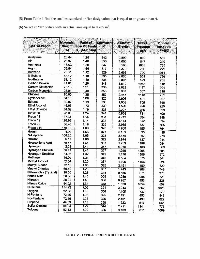
(5) From Table 1 find the smallest standard orifice designation that is equal to or greater than A.
(6) Select an “H” orifice with an actual area equal to 0.785 in2.
TABLE 2 - TYPICAL PROPERTIES OF GASES

Inlet and Outlet Piping ConsiderationsWhile the detailed design or stress analysis of the inlet and outlet piping of pressure relief valves is notwithin the scope of this course, some important considerations are worth mentioning:
Satisfactory operation of a pressure relief valve requires that it be mounted vertically, preferably on anozzle at the top of a vessel or on a tee connection on top of a pipeline. The minimum inlet piping sizeshould be equal in size to the pressure relief valve; the length should be minimized to reduce pressuredrop and bending moments resulting from the reaction thrust developed from the discharging fluid. Arule of thumb is to design the inlet piping such that the total pressure drop in the inlet piping does notexceed 3% of the valve set pressure. When a single pressure relief valve is installed to protect severalvessels, the connecting piping between these vessels should be adequate in size to keep the pressuredrop within these limits.
The type of discharge piping selected will depend largely on the hazardous nature of the service and onthe value of the material that might be lost through a discharge event. For air or non-hazardous gasservice, the discharge piping is normally directed vertically and extended such that it does not present asafety concern. Discharge elbows fitted with drain lines are normally used on steam and vaporservices. The vapor discharge from these elbows is directed into a larger diameter riser pipe that isindependently supported. The discharge piping should be extended vertically downward to a suitabledrain for non-hazardous liquid service. A closed discharge piping system is required for hazardousservices, or for services involving expensive chemicals. Collection systems for these categories offluids may consist of a considerable quantity of piping with numerous pressure relief valvesdischarging into a common manifold. The pressure drop through this type of piping system must becalculated accurately, taking into consideration the fact that simultaneous discharge events may occur. The classical methods for pressure drop determination can be employed for both inlet and outlet pipingarrangements. Values for the density, velocity, and viscosity of the discharging fluid should be basedon the average pressure and temperature of the respective pipe component. The formation of hydrates,polymerization, and fluid solidification in pressure relief valve piping might be an additional concern. A rule of thumb is to design the discharge piping such that the total pressure drop in the outlet pipingdoes not exceed 10% of the valve set pressure.
Supports for pressure relief valve piping should be designed to minimize the transference of pipe loadsto the valve body. Allowance shall be made for piping expansion in cases of high temperature service;valve displacement due to thermal expansion may cause valve leakage or faulty operation. The internalpressure, dead loads, thermal expansions, reaction thrust, resulting dynamic forces, and resultingbending stresses due to discharging fluid will be exerted on the pressure relief valve inlet and outletbends and elbows.
Additional considerations are:
1. Design discharge piping with clean-outs to preclude internal obstructions.2. Test the piping hydrostatically to 150% of the maximum anticipated pressure of the discharge system.3. Provide covers or caps to prevent the intrusion and accumulation of rain or the entrance of
birds or rodents.4. Design piping to be self-draining.

Viscous Fluid ConsiderationsThe procedure to follow to correct for a viscous fluid, i.e. a fluid whose viscosity is greater than 150centipoise (cP) is to:
1. Determine a preliminary required pressure relief valve orifice size (effective area) discounting anyeffects for viscosity. This is done by using the standard liquid sizing formula and setting theviscosity correction factor Kv = 1.0. Select the standard orifice size letter designation that has anactual area equal to or greater than this effective area.
2. Use the actual area of the viscous trial size orifice to calculate a Reynolds number (RNE) using thefollowing formula:
(7)RG QANE =
2800µ
3. Use the Reynolds number calculated in Step 2 to calculate a viscosity correction factor Kv from thefollowing equations:
For RNE < 200,(8)K Rv NE= −0 27 0 65. ln .
For 200 " RNE < 10,000,
(9)K R Rv NE NE= − + +0 00777 0165 01282. (ln ) . ln .
4. Determine a corrected required effective area of the pressure relief valve orifice using the standardliquid sizing formula and the value of Kv determined in Step 3.
5. Compare the corrected effective area determined in Step 4 with the chosen actual orifice area inStep 1. If the corrected effective area is less than the actual trial area assumed in Step 1, then theinitial viscous trial size assumed in Step 1 is acceptable. Repeat this iterative process until anacceptable size is found.
EXAMPLE 4 (Viscous Liquid Application)
Given:Fluid: No. 6 Fuel OilRequired Capacity: 1,200 gal/minSet Pressure: 150 psigOverpressure: 10%Back Pressure: AtmosphericInlet relieving Temperature: 60°FDynamic Viscosity: 850 cPSpecific Gravity: 0.993
Find: The correct size standard orifice to meet the given requirements.
Solution:
(1) Since the overpressure is < 25%, determine the correction factor Kp from Equation 1:
K overpressure overpressurep = − + +0 0014 0 073 0 0162. (% ) . (% ) .
= − + + = . . . .0 0014 10 0 073 10 0 016 0 612( ) ( )
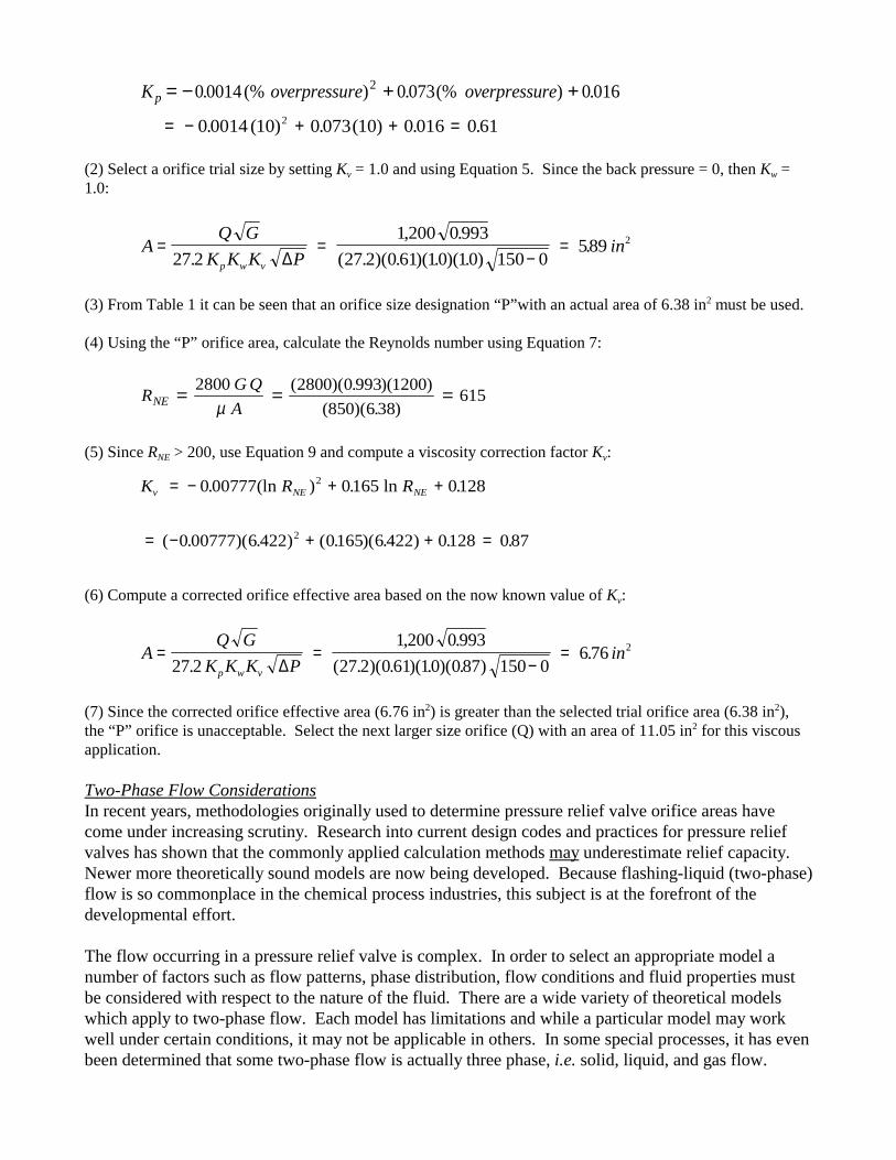
(2) Select a orifice trial size by setting Kv = 1.0 and using Equation 5. Since the back pressure = 0, then Kw =1.0:
AQ G
K K K Pin
p w v
= =−
=27 2
1 200 0 99327 2 0 61 10 10 150 0
589 2
., .
( . )( . )( . )( . ).
∆
(3) From Table 1 it can be seen that an orifice size designation “P”with an actual area of 6.38 in2 must be used.
(4) Using the “P” orifice area, calculate the Reynolds number using Equation 7:
R G QANE = = =
2800 2800 0 993 12006 38
615µ
( )( . )( )(850)( . )
(5) Since RNE > 200, use Equation 9 and compute a viscosity correction factor Kv:
K R Rv NE NE= − + +0 00777 0165 01282. (ln ) . ln .
= − + + =( . )( . ) ( . )( . ) . .0 00777 6 422 0165 6 422 0128 0872
(6) Compute a corrected orifice effective area based on the now known value of Kv:
AQ G
K K K Pin
p w v
= =−
=27 2
1 200 0 99327 2 0 61 10 087 150 0
6 76 2
., .
( . )( . )( . )( . ).
∆
(7) Since the corrected orifice effective area (6.76 in2) is greater than the selected trial orifice area (6.38 in2),the “P” orifice is unacceptable. Select the next larger size orifice (Q) with an area of 11.05 in2 for this viscousapplication.
Two-Phase Flow ConsiderationsIn recent years, methodologies originally used to determine pressure relief valve orifice areas havecome under increasing scrutiny. Research into current design codes and practices for pressure reliefvalves has shown that the commonly applied calculation methods may underestimate relief capacity. Newer more theoretically sound models are now being developed. Because flashing-liquid (two-phase)flow is so commonplace in the chemical process industries, this subject is at the forefront of thedevelopmental effort.
The flow occurring in a pressure relief valve is complex. In order to select an appropriate model anumber of factors such as flow patterns, phase distribution, flow conditions and fluid properties mustbe considered with respect to the nature of the fluid. There are a wide variety of theoretical modelswhich apply to two-phase flow. Each model has limitations and while a particular model may workwell under certain conditions, it may not be applicable in others. In some special processes, it has evenbeen determined that some two-phase flow is actually three phase, i.e. solid, liquid, and gas flow.
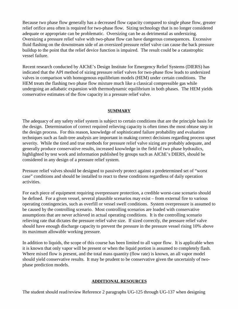
Because two phase flow generally has a decreased flow capacity compared to single phase flow, greaterrelief orifice area often is required for two-phase flow. Sizing technology that is no longer consideredadequate or appropriate can be problematic. Oversizing can be as detrimental as undersizing. Oversizing a pressure relief valve with two-phase flow can have dangerous consequences. Excessivefluid flashing on the downstream side of an oversized pressure relief valve can cause the back pressurebuildup to the point that the relief device function is impaired. The result could be a catastrophicvessel failure.
Recent research conducted by AIChE’s Design Institute for Emergency Relief Systems (DIERS) hasindicated that the API method of sizing pressure relief valves for two-phase flow leads to undersizedvalves in comparison with homogenous equilibrium models (HEM) under certain conditions. TheHEM treats the flashing two phase flow mixture much like a classical compressible gas whileundergoing an adiabatic expansion with thermodynamic equilibrium in both phases. The HEM yieldsconservative estimates of the flow capacity in a pressure relief valve.
SUMMARY
The adequacy of any safety relief system is subject to certain conditions that are the principle basis forthe design. Determination of correct required relieving capacity is often times the most obtuse step inthe design process. For this reason, knowledge of sophisticated failure probability and evaluationtechniques such as fault-tree analysis are important in making correct decisions regarding process upsetseverity. While the tired and true methods for pressure relief valve sizing are probably adequate, andgenerally produce conservative results, increased knowledge in the field of two phase hydraulics,highlighted by test work and information published by groups such as AIChE’s DIERS, should beconsidered in any design of a pressure relief system.
Pressure relief valves should be designed to passively protect against a predetermined set of “worstcase” conditions and should be installed to react to these conditions regardless of daily operationactivities.
For each piece of equipment requiring overpressure protection, a credible worst-case scenario shouldbe defined. For a given vessel, several plausible scenarios may exist – from external fire to variousoperating contingencies, such as overfill or vessel swell conditions. System overpressure is assumed tobe caused by the controlling scenario. Most controlling scenarios are loaded with conservativeassumptions that are never achieved in actual operating conditions. It is the controlling scenariorelieving rate that dictates the pressure relief valve size. If sized correctly, the pressure relief valveshould have enough discharge capacity to prevent the pressure in the pressure vessel rising 10% aboveits maximum allowable working pressure.
In addition to liquids, the scope of this course has been limited to all vapor flow. It is applicable whenit is known that only vapor will be present or when the liquid portion is assumed to completely flash. Where mixed flow is present, and the total mass quantity (flow rate) is known, an all vapor modelshould yield conservative results. It may be prudent to be conservative given the uncertainly of two-phase prediction models.
ADDITIONAL RESOURCES
The student should read/review Reference 2 paragraphs UG-125 through UG-137 when designing

pressure relief systems and selecting and sizing pressure relief valves.
The American Society of Mechanical Engineers American Petroleum InstituteUnited Engineering Center 2101 L Street Northwest345 East 47th Street Washington, DC 20037New York, NY 10017 www.api.orgwww.asme.org
GLOSSARY
This section contains common and standard definitions related to pressure relief valves. It is inaccordance with generally accepted terminology.
accumulation – a pressure increase over the maximum allowable working pressure (MAWP) of theequipment being protected, during discharge through the pressure relief valve, usually expressed as apercentage of MAWP. Compare with overpressure.
actual discharge area – the net area of a selected orifice which dictates the pressure relief valverelieving capacity.
back pressure – the static pressure existing at the outlet of a pressure relief valve due to pressure in thedischarge system.
balanced safety relief valve – a pressure relief valve which incorporates means of minimizing theeffect of back pressure on the operational characteristics (opening pressure, closing pressure, andrelieving capacity).
blowdown – the difference between actual lifting pressure of a pressure relief valve and actual reseatingpressure expressed as a percentage of set pressure.
blowdown pressure – the value of decreasing inlet static pressure at which no further discharge isdetected at the outlet of a pressure relief valve after the valve has been subjected to a pressure equal toor above the lifting pressure.
built-up back pressure – pressure existing at the outlet of a pressure relief valve caused by the flowthrough that particular valve into a discharge system.
chatter – abnormal rapid reciprocating motion of the movable parts of a pressure relief valve in whichthe disc contacts the seat.
closing pressure – the value of decreasing inlet static pressure at which the valve disc reestablishescontact with the seat or at which lift become zero.
coefficient of discharge – the ratio of the measured relieving capacity to the theoretical relievingcapacity.
constant back pressure – a superimposed back pressure which is constant with time.
conventional safety relief valve – a pressure relief valve which has its spring housing vented to the

discharge side of the valve. The operational characteristics (opening pressure, closing pressure, andrelieving capacity) are directly affected by changes in the back pressure on the valve.
design pressure – the value selected for the design of equipment for the most severe condition ofcoincident pressure and temperature expected in normal operation, with provision for a suitable marginabove these operating conditions to allow for operation of the pressure relief valve. The designpressure usually becomes the maximum allowable working pressure.
discharge area – see actual discharge area.
effective discharge area – a nominal or computed area of flow through a pressure relief valve,contrasted to actual discharge area. For use in recognized flow formulas to determine the requiredcapacity of a pressure relief valve.
flow capacity – see rated relieving capacity.
flow-rating pressure – the inlet static pressure at which the relieving capacity of a pressure relief valveis measured.
inlet size – the nominal pipe size of the inlet of a pressure relief valve, unless otherwise designated.
lift – the actual travel of the disc away from the closed position when a valve is relieving.
maximum allowable working pressure – (1) the pressure determined by employing the allowablestress values of the materials used in the construction of the equipment. It is the least value ofallowable pressure value found for any component part of a piece of equipment for a giventemperature. The equipment may not be operated above this pressure and consequently, it is thehighest pressure at which the primary pressure relief valve is set to open. (2) the maximum gagepressure permissible at the top of a pressure vessel in its normal operating position at the designatedcoincident temperature specified for that pressure.
nozzle constant, nozzle coefficient - a variable in the standard gas and vapor sizing formula which isdependent on the specific heat ratio of the fluid. See equation 6, Figure 2, or Table 8.
operating pressure – the service pressure to which a piece of equipment is usually subjected.
orifice area – see actual discharge area.
outlet size – the nominal pipe size of the outlet of a pressure relief valve, unless otherwise designated.
overpressure – a pressure increase over the set pressure of a pressure relief valve, usually expressed apercentage of set pressure. Compare with accumulation.
pilot-operated pressure relief valve – a pressure relief valve in which the major relieving device iscombined with and is controlled by a self-actuated pressure relief valve.
pressure relief valve – a generic term for a re-closing spring loaded pressure relief device which isdesigned to open to relieve excess pressure until normal conditions have been restored.

rated relieving capacity – that portion of the measured relieving capacity permitted by the applicablecode of regulation to be used as a basis for the application of a pressure relief valve.
relief valve – a pressure relief valve actuated by inlet static pressure and having a gradual lift generallyproportional to the increase in pressure over opening pressure. It is primarily used for liquid service.
relieving pressure – set pressure plus overpressure.
safety valve – a pressure relief valve actuated by inlet static pressure and characterized by rapidopening or pop action. It is normally used for steam and air service.
safety relief valve – a pressure relief valve characterized by rapid opening or pop action, or by openingin proportion to the increase in pressure over the opening pressure, depending on the application. Itmay be used in either liquid or compressible fluid applications based on configuration.
set pressure – the value of increasing inlet static pressure at which a pressure relief valve begins toopen.
superimposed back pressure – the static pressure existing at the outlet of a pressure relief valve at thetime the valve is required to operate. It is the result of pressure in the discharge system from othersources.
REFERENCES
1. Department of Labor, Occupational Safety and Health Administration, Process Safety Managementof Highly Hazardous Chemicals, 29 CFR 1910.119, February 24, 1992.
2. American Society of Mechanical Engineers, ASME Boiler and Pressure Vessel Code, Section VIII,Pressure Vessels, Division 1, ASME, New York, 2001 plus addenda.
3. American Petroleum Institute, API Recommended Practice 520, Sizing, Selection, and Installationof Pressure-Relieving Devices in Refineries, Part I, Sizing and Selection, API, Washington D.C.,2000.
4. Fisher, H.G., et al., Emergency Relief System Design Using DIERS Technology, AIChE’s DesignInstitute for Emergency Relief Systems, DIERS, AIChE, New York, 1992.
5. Quoc-Khanh, Tran and Reynolds, Melissa, Sizing of Relief Valves for Two-Phase Flow in theBayer Process, Kaiser Engineers PTY Limited, Perth, Western Australia, 2002.
6. Hauptmanns, Ulrich and Yllera, Javier, Fault-tree Evaluation by Monte Carlo Simulation,Chemical Engineering magazine, January 10, 1983.
7. Crosby® Engineering Handbook Technical Publication No. TP-V300, Pressure Relief ValveEngineering Handbook, Crosby Valve Company, Somewhere, somedate.
8. The Crane Company Technical Paper No. 410, Flow of Fluids through Valves, Fittings, and Pipe,25th printing, 1991.

9. Blackwell, Wayne W., Calculating Two-phase Pressure Drop, Chemical Engineering magazine,September 7, 1981, pp. 121-125.