Name this famous bridge which spans the Arno river in Florence: Ponte dei sospiri Ponte Vecchio

SEISMIC RESPONSE ANALYSIS OF MULTISPAN SIMPLY SUPPORTED BRIDGE USING FINITE ELEMENT SCHEME
(CSIBRIDGE)
M. I. Rahman1*, M. M. I. Mukul1#
, M. A. R. Bhuiyan2 and A.K.M. T. A. Khan3
1Student, Department of Civil Engineering, Chittagong University of Engineering and Technology (CUET),
Chittagong-4349, Bangladesh, *Email:[email protected]; #Email: [email protected] 2Professor, Department of Civil Engineering, Chittagong University of Engineering and Technology (CUET),
Chittagong-4349, Bangladesh, Email:[email protected] 3Ph.D. Research Fellow, Department of Civil Engineering, Chittagong University of Engineering and
Technology (CUET), Chittagong-4349, Bangladesh, Email:[email protected]
ABSTRACT
Multi span simply supported (MSSS) bridges are one of the most commonly used bridge
configurations around the world. A number of bridges of this type have undergone significant
damages and even failures in past earthquakes. In this study, seismic response of a MSSS bridge is
analysed using three dimensional bridge analysis and design software namely CSiBridge. An existing
MSSS concrete bridge was considered for the study and has been subjected to El Centro earthquake
ground acceleration. Three different underlying soil conditions have been applied for retrospect in the
soil structure interaction (SSI). As the responses have been measured in terms of pier top
displacements it has been found that MSSS bridges may not experience substantial displacements if
the bridge horizontal layout is linear. Also the soil structure interaction may have less effect on the
responses. However, for varying geometric configuration due to irregular horizontal bridge layout,
noteworthy amount of displacements have been measured.
Keywords: Multi Span Simply Supported Bridge, Laminated Rubber Bearing, Dynamic Analysis, Soil
Structure Interaction, Seismic Performance
1. INTRODUCTION
Bridge is a structure to carry traffic across an obstacle, a discontinuous landscape or opening. MSSS
bridge is one of the most common types of bridges constructed around the world due to its simpler
construction methodology. However, a lot of bridges of this type have experienced damages and
failures during past earthquakes (Diceli and Bruneau, 1995). A number of studies have been
conducted on MSSS bridges. These scholars conducted studies on seismic performance of the steel
slab-on-girder bridges, which were never designed to resist earthquake. In their research, they
performed dynamic response spectrum analysis and investigated the effects of column stiffness,
bearing stiffness, span length on the seismic performance of bridge structures in both longitudinal and
transverse direction. The failure in the study was defined as reaching of columns up to the capacity
delimited by static interaction curve, as per Duan and Chen (1989). It was found that the bridge
performance is negatively altered with increasing span length and the effect of bearing stiffness in
transverse direction is mostly pronounced in case of two span bridges. Also, ground acceleration
needed to initiate pounding between the decks of MSSS steel bridge was found to be as low as 0.1𝑔.
Further research by Dicleli (1996) on MSSS steel highway bridges with steel columns reveals that the
bearing stiffness plays an important role in determining the displacements when excited transversely.
Again, in case of longitudinal excitation the bridge decks may fail by unseating far before the piers
have reached their ultimate capacity. Saadeghvaziri and Rashidi (1997), in their study concerning
steel girder bridge and made a conclusion that it is necessary to capture the pounding of bridge girders
and the post-yielding behavior of the piers. Later a three dimensional analysis shows that the bearing
stiffness is very important when the load is applied transversely (Saadeghvaziri and Rashidi, 1998).

Although, there has been a number of a literature regarding the seismic performance of the MSSS
steel girder bridges, a few have been dedicated towards assessment of seismic performance of MSSS
concrete girder bridges. Concrete bridges usually have large mass which coupled with flexible bearing
may lead to excessive displacements. Craner et al. (2002) studied the seismic performance of MSSS
bridges with a view to retrofitting the expansion joints. Saiidi et al. (2001) terms the unseating as the
most frequent problem of the MSSS bridges. Pounding produces large impact forces in MSSS bridges
propagate in the decks and increase the bearing shear load. The effect of pounding on the seismic was
studied by Saadeghvaziri and Yazdani-Motlagh (2002). They conducted 3D nonlinear finite element
analysis on three MSSS bridges to analyze the effect of impacting taking into consideration the SSI.
In addition, a parametric study was also performed to further study the effects of different parameters.
They concluded that although the impact forces originating from the pounding decreases the
displacements, it can cause larger shear forces in the bearings. Even under low ground accelerations
the bearing might fail due to the shear forces. Also, from the parametric study it was seen that the
seismic behavior is further complicated by the SSI resulting from the impacting. Bi and Hao (2011)
conducted nonlinear 3D finite element analysis on the pounding of decks including torsional response
induced pounding. The results of their study show that considerable damage to the decks may occur
by pounding. Furthermore, unseating and pounding might be worse if the spatial variation of ground
motion is considered. Nielson and DesRoches (2007) investigated seismic performance of typical
MSSS and multi-span continuous concrete girder bridges and compared their responses. The study
done on a three span MSSS bridge for a seismic hazard level of 2% in 50 years suggests that the
bearings of this type of bridge takes majority of the displacement demands by deformation. The
bridge components experience the largest demands when the bridge is loaded longitudinally.
However, the bearing deforms more in case of transverse loading than the longitudinal loading.
The prime objective of this work is to carry out a seismic response analysis of a multi span simply
supported bridge acted upon by far field (FF) earthquake ground accelerations in both longitudinal
and transverse direction with a view to pointing out the common vulnerabilities of MSSS bridge
designs from the analysis. Retrospect into the seismic behaviour of an MSSS bridge and possible
failures or damages such as unseating, pounding of the component decks or decks and abutments,
column displacements along with the influence of local soil on the bridge structure are also goals of
the study. In this regard the bridge forces and displacements of different components have been
studied. With a view to understanding the SSI, three different cases of soil profile have been
employed at the bridge site and response for the cases has been compared. Later taking into account
the irregular horizontal layout of the bridge, comparison between a linear horizontal layout and an
irregular horizontal layout has been illustrated.
2. METHODOLOGY
2.1 Physical Model of the bridge
Situated at the Bahaddarhat intersection of Chittagong city, the Bahaddarhat bridge is 1001 m in
length. There are two abutments at the ends each 165.3 m long. The bridge is a MSSS slab on precast
concrete girder bridge system. The bridge structure consists of total 25 spans of length varying from
35 meters to 42 meters. The heights of the 2.5 m radius circular piers vary from 3.69 m to 7.29 m. The
bridge deck is built of seven prestressed concrete I girder. The concrete slab is 800 mm deep with
asphalt wearing course. The deck is in 4.27 m in width. The girders rest on elastomeric bearings each
has a height of 10 mm. The superstructure of the bridge is shown in Fig. 1. The substructure consists
of 4.27 m long non-prismatic concrete bent cap over 2 m dia. concrete piers. Each pier is connected to
a spread footing foundation. The footings are each made of 16 piles each 40 m long. The tips of the
piles are embedded in a 1100 mm square pile cap.
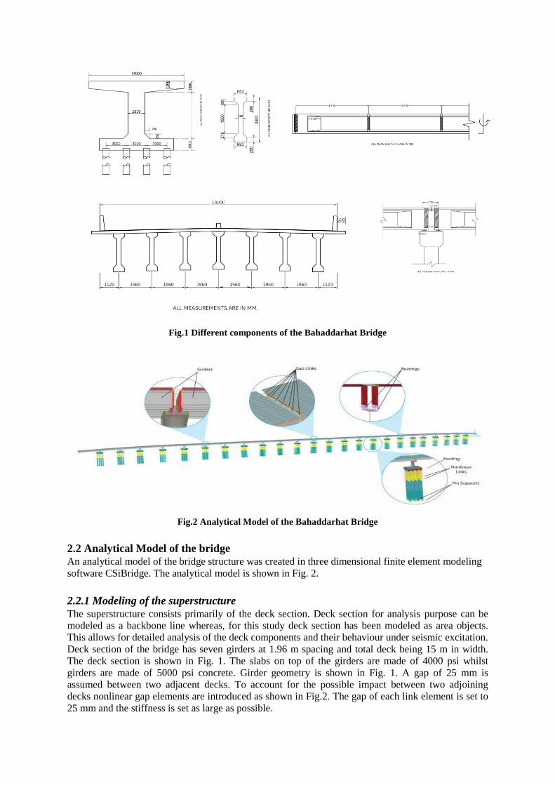
Fig.1 Different components of the Bahaddarhat Bridge
Fig.2 Analytical Model of the Bahaddarhat Bridge
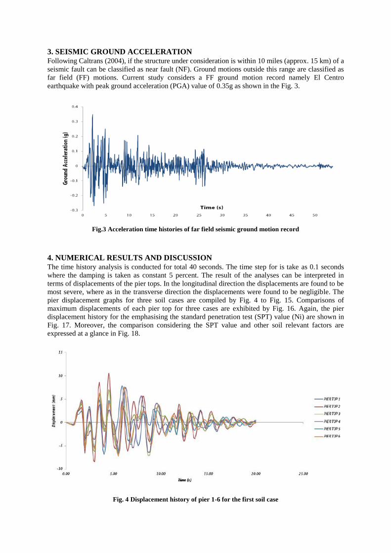
2.2 Analytical Model of the bridge
An analytical model of the bridge structure was created in three dimensional finite element modeling
software CSiBridge. The analytical model is shown in Fig. 2.
2.2.1 Modeling of the superstructure
The superstructure consists primarily of the deck section. Deck section for analysis purpose can be
modeled as a backbone line whereas, for this study deck section has been modeled as area objects.
This allows for detailed analysis of the deck components and their behaviour under seismic excitation.
Deck section of the bridge has seven girders at 1.96 m spacing and total deck being 15 m in width.
The deck section is shown in Fig. 1. The slabs on top of the girders are made of 4000 psi whilst
girders are made of 5000 psi concrete. Girder geometry is shown in Fig. 1. A gap of 25 mm is
assumed between two adjacent decks. To account for the possible impact between two adjoining
decks nonlinear gap elements are introduced as shown in Fig.2. The gap of each link element is set to
25 mm and the stiffness is set as large as possible.

2.2.2 Modeling of the substructure
The substructure consists of abutment, pier, cap beam and footing. The abutment modeling approach
has profound effect on the response of a bridge especially at the ends of a bridge (Aviram et al.,
2008). The simplified abutment model as proposed by several authors used a simplification of the
spring abutment model (Rahman, 2017). This model has a rigid element of length same as the
superstructure width. This element is connected to the superstructure through a rigid joint.
Longitudinal, transverse and vertical nonlinear responses are defined at each end. In the longitudinal
direction however, a series system consisting of a rigid element with shear and moment releases, a
gap element with boundary conditions at each end allowing only longitudinal translation and a zero-
length nonlinear spring with elastic-perfectly-plastic (EPP) backbone curve. The shear resistance of
the bearings at the abutments are ignored. The foundation of the bridge is spread footing type where
each footing consists of 16 pile columns each 1 m in diameter. The slab of the footing is 1.8 m in
thickness. The slab is modeled as thick shell element with 4000 psi concrete. The pile columns of the
footing are 30m in length. Each pile column is divided into 12 sections. At the joining nodes of the
pier column the link elements with stiffness equal to soil stiffness at the corresponding depths are
placed. Three cases of soil profile that were employed are given in the Table 1. The damping of the
soil was taken to be 2%. 4th soil case emphasising the SPT value (Ni) summarized by Table 2.
Table 1: Three cases of soil profile used in the analytical models
Soil Depth (m) Type of soil based on stiffness
Case 1 Case 2 Case 3
0-10 Soft Clay Soft Clay Hard Clay
11-20 Medium Hard Clay Soft Clay Hard Clay
21-30 Hard Clay Soft Clay Hard Clay
30- ~ Hard Clay Hard Clay Hard Clay
Table 2: Relevant data for the 4thsoil case emphasising the standard penetration test (SPT) value
Soil Depth(m) SPT Value
(Ni)
Poission’s Ratio Unit Weight
(KN/m3)
Stiffness Offered by
Soil (KN/m)
1-6 10 0.25 15 15833
7-12 12 0.30 18 24026
13-18 18 0.40 20 54676
19-24 30 0.45 21 53400
25-30 50 0.20 22 65072
2.2.3 Modeling of the rubber bearing
The high damping rubber bearing (HDRB) used in Bahaddarhat bridge that are placed between the
girder and the pier top beam, each consists of 6 rubber layers alternately placed with 3 mm steel
shims. The total height of the rubber layer is 175 mm. The governing equations and their detailing are
available in literature (Khan, 2015). HDRB is modeled using bilinear model. Vertical stiffness of the
HDRB regarded as linear is dependent upon the elasticity of rubber, height of the rubber layers and
the area of the bearing. The horizontal stiffness, characterized by two straight lines is calculated from
the shear modulus of rubber area and the total height of the rubber layers (Rahman, 2017). The post
yield stiffness ratio and damping of the HDRB are taken as 0.22 and 5%, respectively.
Table 3: Geometries and materials properties of the laminated rubber bearing
Sl. No. Particulars Value
01 Cross section of the bearing (mm2) 100000
02 Total thickness of the rubber layers (mm) 175
03 Number of rubber layers 6
04 Thickness of steel layer (mm) 3
05 Nominal shear modulus of rubber (MPa) 1.2
3. SEISMIC GROUND ACCELERATION
Following Caltrans (2004), if the structure under consideration is within 10 miles (approx. 15 km) of a
seismic fault can be classified as near fault (NF). Ground motions outside this range are classified as
far field (FF) motions. Current study considers a FF ground motion record namely El Centro
earthquake with peak ground acceleration (PGA) value of 0.35g as shown in the Fig. 3.
Fig.3 Acceleration time histories of far field seismic ground motion record
4. NUMERICAL RESULTS AND DISCUSSION
The time history analysis is conducted for total 40 seconds. The time step for is take as 0.1 seconds
where the damping is taken as constant 5 percent. The result of the analyses can be interpreted in
terms of displacements of the pier tops. In the longitudinal direction the displacements are found to be
most severe, where as in the transverse direction the displacements were found to be negligible. The
pier displacement graphs for three soil cases are compiled by Fig. 4 to Fig. 15. Comparisons of
maximum displacements of each pier top for three cases are exhibited by Fig. 16. Again, the pier
displacement history for the emphasising the standard penetration test (SPT) value (Ni) are shown in
Fig. 17. Moreover, the comparison considering the SPT value and other soil relevant factors are
expressed at a glance in Fig. 18.
Fig. 4 Displacement history of pier 1-6 for the first soil case
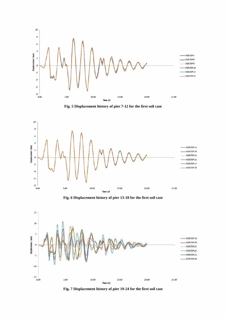
Fig. 5 Displacement history of pier 7-12 for the first soil case
Fig. 6 Displacement history of pier 13-18 for the first soil case
Fig. 7 Displacement history of pier 19-24 for the first soil case

Fig. 8 Displacement history of pier 1-6 for the second soil case
Fig. 9 Displacement history of pier 7-12 for the second soil case
Fig. 10 Displacement history of pier 13-18 for the second soil case

Fig. 11 Displacement history of pier 19-24 for the second soil case
Fig. 12 Displacement history of pier 1-6 for the third soil case
Fig. 13 Displacement history of pier 7-12 for the third soil case

Fig. 14 Displacement history of pier 13-18 for the third soil case
Fig. 15 Displacement history of pier 19-24 for the third soil case
Fig. 16 Comparison of maximum displacements of each pier top for three soil cases

Fig. 17 Displacement history incorporating standard penetration test (SPT) value for pier 1-24
Fig. 18 Comparison of maximum displacements of each pier top considering SPT value
5. CONCLUDING REMARKS
This study presents the seismic performances of a MSSS bridge. Firstly, three cases of soil profile
have been employed in the analytical model of the bridge. In these cases, the horizontal layout of the
bridge is taken to be linear. In the 4th case, the actual irregular horizontal layout is considered. A
linear time history analysis of the bridge model reveals that, for a linear configuration the
displacements of the pier tops are negligible. The effect of the SSI is also been proved to be minimal.
This can be attributed to varying pier height and presence of the abutment at both ends. However, for
the 4th case, displacements were remarkably high as the model had irregular horizontal layout and
curves. Hence, it can be deduced that bridges with horizontal curves and irregular configurations are
more prone to seismic damages than those with simpler linear configuration. One important aspect is
no pounding between two adjacent decks were seen and the gap length between the decks were
proven adequate. Another notable feature is that, in all cases the pier top displacements for the piers
nearest to the abutments are seen to have irregular manner with time, while displacements of pier tops
at other positions are regular and shows almost similar manner.

In current study, four analytical model of a bridge having different types of foundation soil and
configuration are considered for only one earthquake ground motion; however, a more rigorous
modeling of the bridge system is expected for an elaborate numerical investigation since the seismic
responses of such an assemblage would be different if the total assembly of the bridge is considered
under different earthquake ground motion records considering duration, frequency contents and fault-
line characteristics, etc. Instead of the actual horizontal bridge layout profile, a straight layout profile
was adopted except the 4th case. In actual situation irregularity of the bridge configuration may have a
tremendous influence on the bridge behavior. Furthermore, the variability of soil layers is hardly
considered. For accurate modeling of the bridge foundation soil profile, boring log data will be
necessary. The spatial variation of seismic wave is not considered. Consideration of issues like spatial
variability and actual bridge configuration are likely to change the dynamics of the entire bridge
structure. These issues can be dealt with future works.
REFERENCES
Aviram, A; Mackie, KR and Stojadinović, B. 2008.Guidelines for Non-Linear Analysis of Bridge
Structures.Report 2008/03. Pacific Earthquake Engineering Research Center (PEER).
Bi, K and Hao, H. 2011. 3D Pounding Analysis Between Decks and at Abutments of a Bridge
Structure to Multi-component Spatially Varying Ground Motions, Australian EQ Engg. Society Conf.
California Dept. of Transportation (CALTRANS). 2004. Seismic Design Criteria,Sacramento, USA.
Craner, A; Dogan, E and Zia, P. 2002. Seismic Performance of Multisimple-span Bridges Retrofitted
with Link Slabs, Journal of Bridge Engineering, 7(2), pp. 85–93.
Dicleli, M. 1996. Seismic Performance of Multi-Span Simply Supported Highway Bridges Having
Steel Columns, World Conference on Earthquake Engineering (1996).
Dicleli, M and Bruneau, M. 1995. Seismic Performance of Multispan Simply Supported Slab-on-
Girder Steel Highway Bridges, Engineering Structures, 17(01), pp. 4-14.
Duan, L and Chen, WF. 1989. Design Interaction Equation for Steel Beam-Columns, Journal of
Structural Engineering, 5(115), pp. 1225–1243.
Khan, A.K.M. T. A., 2014. An Improved Rheology Model of Laminated Rubber Bearings for Seismic
Analysis of Multi-Span Highway Bridge, M.Sc. Thesis, Dept. of Disas. & Env., CUET, Chittagong.
Nielson, BG, and DesRoches, R. 2007. Seismic Performance Assessment of Simply Supported and
Continuous Multispan Concrete Girder Highway Bridges, Journal of Bridge Engg., 12(5), pp. 85–93.
Rahman, I and Mukul, MMI. 2017. Seismic Response Analysis of Multi-Span Simply Supported
Bridge using CSiBridge, B.Sc. Thesis, Dept. of Civil Engineering, CUET, Chittagong, Bangladesh.
Saadeghvaziri, MA and Rashidi, S. 1997. Seismic Modeling of Multispan Simply-Supported Bridges
using Adina, Computers and Structures, 64(5–6), pp. 1025-1039.
Saadeghvaziri, MA and Rashidi, S. 1998. Effect of Steel Bearings on Seismic Response of Bridges in Eastern United States, 6th U.S. National Conference on Earthquake Engineering (1998).
Saadeghvaziri, MA and Yazdani-Motlagh, A. 2002. Effects of Impact on the Seismic Response of
MSSS bridges, Structures Under Shock and Impact VII, WIT Press (2002).
Saiidi, M; Randall, M; Maragakis, E and Isakovic, T. 2001. Seismic Restrainer Design Methods for
Simply Supported Bridges, Journal of Bridge Engineering, 6(5).