
• Structures • Seismic Sequence stratigraphy • Seismic Facies ...

60th Anniversary State-of-the-Art Reviews
Seismic-Resistant Precast Concrete Structures:State of the Art
Yahya C. Kurama, M.ASCE1; Sri Sritharan, M.ASCE2; Robert B. Fleischman, M.ASCE3;Jose I. Restrepo, M.ASCE4; Richard S. Henry5; Ned M. Cleland, M.ASCE6;
S. K. Ghosh, F.ASCE7; and Patricio Bonelli8
Abstract: Precast concrete facilitates a construction method using durable and rapidly erectable prefabricated members to create cost-effective and high-quality structures. In this method, the connections between the precast members as well as between the membersand the foundation require special attention to ensure good seismic performance. Extensive research conducted since the 1980s has ledto new precast concrete structural systems, designs, details, and techniques that are particularly suited for use in regions of high seismichazard. This paper reviews the state of the art of these advances, including code developments and practical applications, related to fourdifferent systems: (1) moment frames; (2) structural walls; (3) floor diaphragms; and (4) bridges. It is concluded from this review that thewidespread use of precast concrete in seismic regions is feasible today and that the jointed connection innovation introduced through precastresearch leads to improved seismic performance of building and bridge structures. DOI: 10.1061/(ASCE)ST.1943-541X.0001972. © 2018American Society of Civil Engineers.
Author keywords: Code developments; Earthquake resistance; Emulated; Joints; Posttensioning; Precast prestressed concrete;Prestressing; Pretensioning; Seismic design; Unbonded.
Introduction
In precast concrete construction, structural members (e.g., beams,columns, wall panels, and floor units) and architectural members(e.g., cladding) are produced in a manufacturing facility, trans-ported to the structure site, and erected and connected in place.The cost effectiveness and high quality of this construction methodhave resulted in its widespread use, including a number of countrieswith high seismicity (e.g., New Zealand, Japan, and Chile).
The seismic behavior of precast building and bridge structures ishighly dependent on the characteristics (i.e., strength, stiffness, anddeformation capacity) of the connections between the precast struc-tural members and between the members at the base and the foun-dation. Poor performance of precast buildings in past earthquakes
has often been attributed to poorly designed and/or poorly builtconnections (fib 2003). Accordingly, the need to develop newseismic building code requirements for precast construction thatspecifically address the unique role of the precast connectionswas recognized in the United States and elsewhere beginning in the1980s (e.g., Englekirk 1986; Hawkins and Englekirk 1987; Park1995).
In the United States, the first major research study with a focuson the seismic performance of precast building structures wasundertaken during the 1990s at the National Institute of Standardsand Technology (e.g., Cheok and Lew 1993). This study focusedspecifically on building moment frames. A major U.S.–Japan co-operative research program on PREcast Seismic Structural Systems(PRESSS) was initiated in the early 1990s (Priestley 1991). Thisprogram comprised many individual research projects, followedby the design and testing of a culminating five-story precast build-ing structure (Nakaki et al. 1999). These efforts formed the basis ofa number of other subsequent research studies in the United States.In the 2000s, a large research program was conducted on precastfloor diaphragms (Fleischman et al. 2013). In comparison withbuildings, developments in seismic precast concrete bridges werepursued less aggressively until advancements occurred in acceler-ated bridge construction in nonseismic regions.
Extensive research and development on seismic precast buildingstructures have also been undertaken outside the United States(again, research in bridge structures has been more recent). Amongthese, significant research in Japan (since the U.S.–Japan PRESSSprogram) includes the testing of a full-scale four-story buildingusing precast posttensioned concrete members at the E-Defenseshaking table facility (Nagae et al. 2014). In New Zealand, researchprograms in the 1980s and 1990s led to the development of guide-lines for structural precast concrete (CAE 1999) and the implemen-tation of precast construction into building design standards(Park 1995). In addition, research into floor diaphragms resultedin changes in diaphragm seismic design and connection detailing
1Professor, Dept. of Civil and Environmental Engineering andEarth Sciences, Univ. of Notre Dame, 156 Fitzpatrick Hall, Notre Dame,IN 46556 (corresponding author). E-mail: [email protected]
2Wilkinson Chair Professor in Engineering, Dept. of Civil, Constructionand Environmental Engineering, Iowa State Univ., Ames, IA 50011.
3Professor, Dept. of Civil Engineering and Engineering Mechanics,Univ. of Arizona, Tucson, AZ 85721.
4Professor, Dept. of Structural Engineering, Univ. of California atSan Diego, La Jolla, CA 92093.
5Senior Lecturer, Dept. of Civil and Environmental Engineering, Univ.of Auckland, Auckland 1010, New Zealand.
6President, Blue Ridge Design, Inc., 3 W. Piccadilly St., Winchester,VA 22601.
7President, S. K. Ghosh Associates, Inc., 334 East Colfax St., Unit E,Palatine, IL 60067.
8Professor, Dept. of Civil Engineering, Universidad Técnica Federico,Santa María, Valparaiso, Chile.
Note. This manuscript was submitted on January 21, 2017; approved onAugust 22, 2017; published online on January 17, 2018. Discussion periodopen until June 17, 2018; separate discussions must be submitted for in-dividual papers. This paper is part of the Journal of Structural Engineer-ing, © ASCE, ISSN 0733-9445.
© ASCE 03118001-1 J. Struct. Eng.
J. Struct. Eng., 2018, 144(4): 03118001
Dow
nloa
ded
from
asc
elib
rary
.org
by
Uni
vers
ity o
f N
otre
Dam
e on
01/
17/1
8. C
opyr
ight
ASC
E. F
or p
erso
nal u
se o
nly;
all
righ
ts r
eser
ved.
(Fenwick et al. 2010). In Europe, a collaborative five-year researchproject called SAFECASTwas conducted to study the behavior ofprecast concrete buildings under earthquake loading (e.g., Negroet al. 2013; Psycharis and Mouzakis 2012). China, which sufferedsignificant precast building failures in the 1976 Tangshan earth-quake (Housner and Lili 2002) and subsequently moved away fromprecast, has recently been making efforts to revive this constructionform (Seeber 2014).
The previous research on seismic precast building and bridgestructures, spanning more than three decades, has in turn led tochanges to the relevant governing codes and successful implemen-tations in regions of high seismicity. This paper, which provides areview of these advances, is organized into the following major sec-tions on seismic-resistant precast concrete: (1) general concepts;(2) development of seismic provisions in design codes; (3) connec-tions, splices, and anchorages; (4) moment frames; (5) structuralwalls; (6) floor diaphragms; and (7) bridges. Although this reviewpaper attempts to include all major relevant research advances inthe United States and abroad, the discussion of code developmentsis focused mostly on the United States. Furthermore, on-site precast(e.g., tilt-up) and architectural precast are outside the scope of thepaper.
General Concepts
Precast concrete construction for seismic systems can be broadlyclassified into two types, emulative and jointed. Emulative con-struction uses connections that are designed and detailed to makethe performance (in terms of lateral strength, stiffness, and energydissipation) of the precast structure comparable to that of an equiv-alent, conventionally designed, and properly detailed cast-in-placemonolithic reinforced concrete structure (Ericson and Warnes1990). Emulative connections are further divided into two types:ductile and strong. Structures with ductile connections are designedto undergo flexural yielding and form ductile plastic hinges in theconnections across precast member-to-member or member-to-foundation joints, whereas structures with strong connections aredesigned to experience flexural yielding within the precast mem-bers at preselected and appropriately detailed locations adjacent toor away from the joints. This paper refers to the region at the in-tersection of (i.e., between) precast members as a joint, and refers tothe assembly of hardware and anchors across a joint as a connec-tion. Capacity-design principles are used to ensure that strong con-nections remain essentially in the linear-elastic range of behavior,while plastic hinges fully develop elsewhere in the structure.
Jointed construction (also referred to as nonemulative detailingin the literature) uses precast connection concepts that are distinctlydifferent from emulative connections. In this approach, the nonlin-ear rotations of the structure are deliberately concentrated at theends of the precast members in the joint regions (through controlledrocking at the joint interface), without causing significant inelasticbehavior (i.e., damage) in the members. This unique behaviorhas been achieved by using unbonded posttensioning (PT) steel(often using multistrand tendons) as the primary reinforcementin moment frames and walls, as demonstrated in the PRESSS pro-gram (e.g., Nakaki et al. 1999; Priestley et al. 1999) and subsequentresearch.
The objectives of jointed connections, in not attempting to em-ulate the lateral load behavior of monolithic cast-in-place struc-tures, are twofold. First, the concentrated rotations (also referredto as rocking rotations) at the jointed connections significantly re-duce (or eliminate) tension damage in the precast members byallowing the structure to undergo large lateral displacements with
little tensile stresses in the concrete. Second, the PT force providesa large restoring effect that facilitates recentering of the structure atthe end of the seismic loading (often referred to as self-centeringcapability).
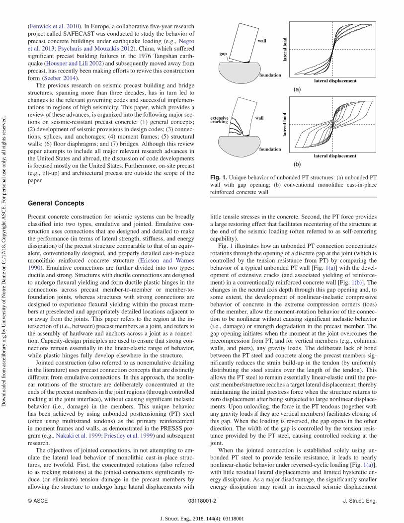
Fig. 1 illustrates how an unbonded PT connection concentratesrotations through the opening of a discrete gap at the joint (which iscontrolled by the tension resistance from PT) by comparing thebehavior of a typical unbonded PT wall [Fig. 1(a)] with the devel-opment of extensive cracks (and associated yielding of reinforce-ment) in a conventionally reinforced concrete wall [Fig. 1(b)]. Thechanges in the neutral axis depth through this gap opening and, tosome extent, the development of nonlinear-inelastic compressivebehavior of concrete in the extreme compression corners (toes)of the member, allow the moment-rotation behavior of the connec-tion to be nonlinear without causing significant inelastic behavior(i.e., damage) or strength degradation in the precast member. Thegap opening initiates when the moment at the joint overcomes theprecompression from PT, and for vertical members (e.g., columns,walls, and piers), any gravity loads. The deliberate lack of bondbetween the PT steel and concrete along the precast members sig-nificantly reduces the strain build-up in the tendon (by uniformlydistributing the steel strains over the length of the tendon). Thisallows the PT steel to remain essentially linear-elastic until the pre-cast member/structure reaches a target lateral displacement, therebymaintaining the initial prestress force when the structure returns tozero displacement after being subjected to large nonlinear displace-ments. Upon unloading, the force in the PT tendons (together withany gravity loads if they are vertical members) facilitates closing ofthis gap. When the loading is reversed, the gap opens in the otherdirection. The width of the gap is controlled by the tension resis-tance provided by the PT steel, causing controlled rocking at thejoint.
When the jointed connection is established solely using un-bonded PT steel to provide tensile resistance, it leads to nearlynonlinear-elastic behavior under reversed-cyclic loading [Fig. 1(a)],with little residual lateral displacements and limited hysteretic en-ergy dissipation. As a major disadvantage, the significantly smallerenergy dissipation may result in increased seismic displacement
lateral displacement
late
ral l
oad
gap
wall
foundation
lateral displacement
late
ral l
oad
extensivecracking
wall
foundation
(a)
(b)
Fig. 1. Unique behavior of unbonded PT structures: (a) unbonded PTwall with gap opening; (b) conventional monolithic cast-in-placereinforced concrete wall
© ASCE 03118001-2 J. Struct. Eng.
J. Struct. Eng., 2018, 144(4): 03118001
Dow
nloa
ded
from
asc
elib
rary
.org
by
Uni
vers
ity o
f N
otre
Dam
e on
01/
17/1
8. C
opyr
ight
ASC
E. F
or p
erso
nal u
se o
nly;
all
righ
ts r
eser
ved.
demands for the precast structure (Priestley and Tao 1993; Farrowand Kurama 2003; Seo and Sause 2005). Thus, to comply with seis-mic design requirements, precast structures with jointed connec-tions are often designed with external or internal supplementalenergy dissipation components (e.g., through yielding or friction/sliding), while maintaining their unique features, as described fordifferent structural systems subsequently in this paper. Another po-tential drawback of jointed connections is that the compression toeof the rocking precast member may experience damage throughcrushing of the concrete. Typically, this is limited to the cover con-crete as long as the core region is sufficiently confined (e.g., Smithet al. 2013, 2015). The cover concrete damage can also be preventedor significantly reduced (e.g., Nazari et al. 2017) by using engi-neered cementitious composites (ECCs) in the vicinity of the joint,steel or fiber-reinforced polymer (FRP) jacketing, steel armoring,and, more recently, by using rubber sheets, polymer joints, andrubber bearing joints at the appropriate locations.
Development of Seismic Provisionsin Design Codes
Seismic design of precast concrete structures in most U.S. juris-dictions today is in accordance with the International BuildingCode IBC-15 (IBC 2014), which adopts two key standards, ASCE/SEI 7-10 (ASCE 2013) and ACI 318-14 (ACI 2014). Other impor-tant resource documents are the National Earthquake HazardsReduction Program (NEHRP) Provisions (BSSC 2015), PCIDesign Handbook (PCI 2010), and PCI Seismic Design Manual(Cleland and Ghosh 2012).
Seismic Force Resisting Systems for BuildingStructures
The ACI 318 code included seismic design provisions for precastconcrete for the first time in 2002, largely based on the 2000NEHRP Provisions (BSSC 2001). These provisions provided em-ulative design specifications applicable to special moment framesand structural walls. Design of moment frames involving jointedconnections was allowed based on a validation testing document,the current designation of which is ACI 374.1-05 (ACI 2005). ACI318-08 (ACI 2008) added jointed design provisions for specialstructural walls, based on another validation testing document,ACI ITG 5.1-07 (ACI 2007). Hawkins and Ghosh (2006), Ghosh(2004), and D’Arcy et al. (2003) provided more information on thehistorical evolution of precast seismic design provisions for build-ings in the United States. Specific code provisions for different seis-mic building structural systems appear in the sections “MomentFrames” and “Structural Walls.”
Among other countries, the New Zealand Concrete StructuresStandard, NZS 3101 (Standards New Zealand 2006), contains spe-cific provisions for the seismic design of precast concrete members,including both emulative and jointed construction. Appendix B ofNZS 3101 includes special provisions for the seismic design ofductile jointed precast structural systems, which were first intro-duced in the 2006 edition. In addition, there are guidelines specificto precast concrete structures, such as CAE (1999) and the PRESSSdesign handbook (Pampanin et al. 2010).
Floor Diaphragms for Building Structures
With regard to precast floor diaphragms in the United States, theASCE/SEI 7-16 (ASCE 2016) standard adopted two new sections(i.e., Sections 12.10.3 and 14.2.4) based on significant updates todiaphragm design in the 2015 NEHRP provisions (BSSC 2015).
ASCE/SEI 7-16 Section 12.10.3 presents an alternative determina-tion of the diaphragm design force based on rational methods,whereas Section 14.2.4 contains options for the seismic design ofdiaphragms based on Zhang and Fleischman (2016). Because ofthe recent nature of these developments, the “Floor Diaphragms”section of this paper includes a detailed treatment of this topic.Similar new recommendations have been developed in New Zealand[NZS 1170.5 (Standards New Zealand 2004) and NZS 3101(Standards New Zealand 2006)].
Bridge Structures
Code provisions for using precast concrete in seismic bridge designhave not fully evolved. This lack of code provisions stems from theinfrequent use of precast concrete historically in seismic design ofbridges. Specifically, the use of precast girders in bridges has beenhampered by two design criteria: (1) assuming that a positive mo-ment connection between precast girders and the bent cap beamcannot be reliably developed, formation of a plastic hinge at thecolumn (or pier) top is not permitted, making this construction op-tion less cost effective compared with the cast-in-place alternative(Caltrans 2013; Vander Werff et al. 2015); and (2) a connectioninvolving mild steel reinforcement is required between the capbeam and girders to ensure satisfactory shear transfer across thecap beam-to-girder joint when vertical acceleration exceeds 0.25 g(Caltrans 2013). As such, the use of precast girders in bridge struc-tures, when it occurs, is often motivated by overcoming construc-tion challenges associated with cast-in-place concrete.
Research to address the aforementioned concerns and the use ofother forms of precast concrete in seismic bridge design have beencompleted in recent years. Outcomes of these studies and experi-ences using precast concrete in selected prototype bridges haveled to the development of design guidelines by state agencies(e.g., Departments of Transportation in California, Utah, andWashington). Amalgamation of these guidelines can eventuallylead to generalized seismic design provisions.
Connections, Splices, and Anchorages
Connections in seismic precast structural systems are typicallycompleted in the field during erection. A construction space is oftencreated at the joints for tolerances and alignment purposes. Thisspace is filled with high-strength, nonshrink grout, sometimes in-cluding synthetic fibers. The connections across the joints can bemade using an assortment of hardware embedded in the precastmembers, anchorage of deformed mild steel reinforcement, and/orbonded or unbonded PT (PCI 2010; PTI 2006). ACI 550R-96 (ACI2001) gives connection details specific to emulative construction.
Hardware connections and bonded PT are typically used in em-ulative construction. Hardware connections, which can be bolted orwelded, include various types of embedded plates and commercialinserts. For many types of hardware connections, completing theload path depends on anchorage to concrete, which is not discussedherein but is provided in Chapter 17 of ACI 318-14.
Anchorage of deformed mild steel reinforcing bars is importantin both emulative and jointed precast construction. Anchorage ofthese bars can be achieved using high-strength, nonshrink grout(i.e., a prepackaged mixture of cement, sand, water, and admixturesfor bonding reinforcement in sleeves or ducts) or in-situ concrete, ormechanical splicing in the field. Normally, the lap lengths requiredin accordance with Section 25.5 of ACI 318-14 are too long for theassembly of precast members. Thus, mechanical splice devices withshort projecting lengths of bars are often used across both horizon-tal and vertical joints. These splice devices are typically rigid;
© ASCE 03118001-3 J. Struct. Eng.
J. Struct. Eng., 2018, 144(4): 03118001
Dow
nloa
ded
from
asc
elib
rary
.org
by
Uni
vers
ity o
f N
otre
Dam
e on
01/
17/1
8. C
opyr
ight
ASC
E. F
or p
erso
nal u
se o
nly;
all
righ
ts r
eser
ved.
hence, unless detailed carefully, they can force the bar elongation tooccur over a very short length just outside the splice, which can leadto high local strains and early bar fracture (Marsh et al. 2011). Thiscan be mitigated by the use of debonded lengths (or stretch lengths)to distribute the steel strains over a finite length of the bars in jointedprecast construction, as has been demonstrated for both frame andwall systems (e.g., Priestley et al. 1999; Smith et al. 2011).
Type 2 splices are commonly used for deformed mild steelreinforcing bars in precast concrete construction. According toACI 318-14 Section 18.2.7.1, Type 2 splices for seismic designmust be “capable of developing the specified tensile strength of thespliced bars.” ACI 318-14 permits these splices to be used at anylocation, including yielding regions, except for ductile connectionsin special moment frames, where they are not permitted closer thanhalf the beam depth from the column face. According to SectionR18.2.7.1 of ACI 318-14, the requirements for Type 2 splices areintended to result in a device that is “capable of sustaining inelasticstrains through multiple cycles.” However, grouted Type 2 spliceshave experienced failure under cyclic loading due to bond pulloutin jointed precast walls (Smith and Kurama 2014) tested in accor-dance with ACI ITG 5.1-07 (ACI 2007). Research is currentlyunderway (Aragon et al. 2017) to validate an improved groutedconnector for ductile reinforcing bars to not only meet Type 2 re-quirements, but also sustain extreme postyield cyclic bar strainsrequired in jointed precast seismic systems.
Unbonded PT is common in jointed construction. Anchoragesfor unbonded PT strands have been the subject for several studies(Walsh and Kurama 2010, 2012; Sideris et al. 2014a; Musselmanet al. 2015). These studies have shown that premature wire fracturesof unbonded seven-wire strand can occur inside industry-standardPT anchorages. To prevent this behavior, the studies have recom-mended maximum allowable strand strains for use in the design ofjointed precast structures. Walsh et al. (2015) showed that higher-performing PT anchors that allow greater strand strains withoutfracture can be achieved by slightly changing the anchor wedgegeometry.
Moment Frames
This section summarizes the developments associated with usingprecast concrete in seismic design of moment frames.
Moment Frames with Emulative Connections
Sections 18.9.2.1 and 18.9.2.2 of ACI 318-14 provide emulativedesign provisions for “special” precast concrete moment frames.As with monolithic cast-in-place frames, column bases and beamends are typically selected as the plastic hinge locations in emula-tive precast frames. Providing adequate confinement reinforcementin these critical regions ensures formation of ductile plastic hinges.Nonlinear action in other regions is prevented by using capacity-design principles. Designers must carefully select locations ofstrong connections or take other measures, such as debonding ofreinforcing bars in highly stressed regions, to avoid strain concen-trations that have the potential to cause premature fracture ofreinforcement.
Development of different emulative connection concepts(e.g., Park and Bull 1986; Park 1990; Restrepo et al. 1995) andrelated design documents (e.g., AIJ 2000; Park 1995; ACI2001) have led to the frequent use of these systems in Japan,New Zealand, and to some extent, in the United States. Frame struc-tures may use cast-in-place or precast columns with precast or par-tially precast beams. Partially precast beams may use exposedreinforcement or a precast shell for the beams. Figs. 2(a–c) show
examples of emulative beam-to-column connections. Typical emu-lative frame construction built from the 1980s onward generallyperformed well during the Canterbury earthquakes in New Zealand(Fleischman et al. 2014). Walsh et al. (2016) tested damaged precastframes extracted from a 20-story building to assess their residualcapacity and reparability. These tests confirmed the behavior of em-ulative precast frames tested previously in the laboratory (Restrepoet al. 1995) and also showed that flexural hinging in the beamscan be repaired with no significant reduction in seismic capacity.
In Japan, the emulative concept has generally favored the use ofbonded PT (Nishiyama 1990). This framing system has used multi-story columns and single-bay beams with bonded PT establishingthe beam-to-column connections [Fig. 2(d)]. Unlike emulativeconnections with deformed mild steel reinforcement, this framingconcept provides reduced energy dissipation because of the use ofPT steel. Furthermore, inelastic strains in the PT steel can causeprestress losses under cyclic loading. The plastic hinging in thissystem will occur at the beam ends and likely penetrate into thejoint (fib 2003). As a result, debonding of the strands within theplastic hinge region is possible, minimizing the loss of prestressing.Muguruma et al. (1995) reported that more than 150 momentframes designed with this concept performed well in the 1995 Kobeearthquake in Japan. Importantly, these frames recentered at the endof ground shaking, enabling buildings to be functional followingthe Kobe earthquake, despite the potential for prestress loss andlow amount of energy dissipation.
Moment Frames with Jointed Connections
According to Section 18.9.2.3 of ACI 318-14, special precastmoment-resisting frames with jointed connections not satisfyingSections 18.9.2.1 and 18.9.2.2 of ACI 318-14 are permitted, pro-vided they satisfy ACI 374.1-05 (ACI 2005). Section 18.9.2.3 im-poses additional criteria related to the use of representative detailsand materials if test validation is required, and provides a guidingdesign procedure to identify the load path or mechanism by whichthe frame resists gravity and earthquake effects.
Moment frames with jointed connections frequently use multi-story columns and single-bay beams, although use of single-storycolumns and multibay beams has also been suggested. Fully orpartially unbonded PT through the beams is the primary feature inthese frames, which are typically designed to remain linear-elasticunder the design-level earthquake. When the frames are constructedwith single-bay beams, unbonded PT is used to establish the con-nections between the columns and beams. Because the PT steel isdesigned to remain linear-elastic, a jointed frame provides lowerenergy dissipation capacity than frames with bonded prestressing(El-Sheikh et al. 1999). Consequently, supplemental damping forframes with unbonded PT has been tested (e.g., Nakaki et al. 1999;Priestley et al. 1999; Morgen and Kurama 2004, 2007, 2008).
The hybrid frame concept is the most successful jointed frame todate. The term hybrid refers to the combined use of unbonded PTsteel and deformed mild steel reinforcing bars to form the beam-to-column connections [Fig. 3(a)]. The PT steel is placed at or near themidheight of the beam, whereas the mild steel bars are placed closerto the top and bottom of the beam. Under lateral loads, gaps form atthe joints at the beam ends when the moment at the connection ex-ceeds the decompression moment. The mild steel bars contribute tothe moment resistance and are designed to yield and provide energydissipation during the gap opening–closing behavior (i.e., rockingrotations) under cyclic loading. To control the maximum tensionstrain demands on the mild steel bars and prevent their prematurelow-cycle fatigue fracture, these bars are debonded over a shortlength (stretch length) in or adjacent to the connection region.
© ASCE 03118001-4 J. Struct. Eng.
J. Struct. Eng., 2018, 144(4): 03118001
Dow
nloa
ded
from
asc
elib
rary
.org
by
Uni
vers
ity o
f N
otre
Dam
e on
01/
17/1
8. C
opyr
ight
ASC
E. F
or p
erso
nal u
se o
nly;
all
righ
ts r
eser
ved.

As part of the concept development, several interior hybrid mo-ment frames were tested at the National Institute for Standards andTechnology (Cheok and Lew 1993; Stone et al. 1995). Althoughthese tests used partially bonded PT strands, the strands were un-bonded in the critical region that included the column and a shortdistance within the beam on either side of the column. In the cul-mination of the PRESSS program, a five-story moment frame
consisting of several different jointed connections was subjectedto pseudodynamic testing, which included a three-story, two-bayhybrid frame [Fig. 3(b)] (Priestley et al. 1999; Sritharan 2002).These tests validated the superior performance of this jointed sys-tem to provide (1) sufficient energy dissipation, (2) minimal struc-tural damage, and (3) recentering capability. A design document,ACI ITG 1.2-03 (ACI 2003), was subsequently developed for
(b) (a)
Unbonded post-tensioning
Mild steel reinforcement
Grout with fiber Rebar debonded over a short length
Fig. 3. Example of a jointed frame beam-to-column connection and its use in a system: (a) jointed hybrid beam-to-column connection(image courtesy of S. Nakaki, Nakaki Structural Design, Tustin, CA); (b) three-story hybrid frame tested in the PRESSS building (image bySri Sritharan)
Fig. 2. Example emulative and bonded PT beam-to-column connections: (a) emulative connection with in-situ concrete; (b) emulative connectionwith grouted bars; (c) emulative corner beam-to-column connection; (d) bonded PT beam-to-column connection [(a, b, and d) adapted from fibBulletin 27: “Seismic design of precast concrete building structures“ (October 2003), with permission from the International Federation for StructuralConcrete (fib); (c) image by Jose I. Restrepo]
© ASCE 03118001-5 J. Struct. Eng.
J. Struct. Eng., 2018, 144(4): 03118001
Dow
nloa
ded
from
asc
elib
rary
.org
by
Uni
vers
ity o
f N
otre
Dam
e on
01/
17/1
8. C
opyr
ight
ASC
E. F
or p
erso
nal u
se o
nly;
all
righ
ts r
eser
ved.

hybrid moment frames with jointed precast beam-to-column con-nections. As required by Section 18.2.1.7 of ACI 318-14, the ACIITG 1.2-03 guidelines ensure that hybrid frames have strength andtoughness at least equal to those of comparable monolithic framessatisfying Chapter 18 of ACI 318-14.
One issue with hybrid moment frames is that the gap openingat the beam-to-column joints can damage the adjacent floor slab.This has led to configurations that reduce damage to the floor slabduring cyclic loading, such as the TYC-gap connection used in thePRESSS test building (Priestley et al. 1999; Sritharan 2002) and aslotted beam detail tested by Muir et al. (2012).
Since the development of design guidelines for hybrid frames,precast frame research for seismic applications has subsided. At thesame time, hybrid frame applications in commercial structures
grew in seismic regions, demonstrating the practical viability forwidespread use in low-rise and mid-rise buildings. Shutt (1997)explained the advantages of the hybrid frame, particularly forparking structures, citing several applications [e.g., Fig. 4(a)].The hybrid frame concept was also used in the 39-story Paramountapartment building [Fig. 4(b)] in San Francisco (Englekirk 2002)—the tallest concrete-framed structure in a high-seismic zone in theUnited States at the time of completion in 2002. The next section,“Structural Walls,” provides two other applications of hybridframes.
Structural Walls
Structural walls are a commonly used lateral load resisting memberin building design due to their large lateral stiffness, strength, andcost effectiveness. Precast walls can be constructed using rectangu-lar uniformly thick wall panels with emulative or jointed connec-tions. Possible configurations include single or coupled walls, witheach wall comprising individual or multiple panels (Fig. 5). In amultipanel wall, vertical stacks of panels (typically one story high)are connected across horizontal joints. Coupled walls consist of twoor more vertically oriented walls connected together in the sameplane by connectors or coupling beams.
Structural Walls with Emulative Connections
ACI 318-14 Section 18.11.2.1 requires special emulative precastwalls to satisfy the requirements in Section 18.10 for special mono-lithic cast-in-place walls. It is also required that in the connectionsbetween the wall panels, or between the base panel and the foun-dation, yielding be limited to steel components or reinforcement,and that the parts of the connection that are not intended to yield
Fig. 4. Unbonded PT frames: (a) parking structure under constructionat University of California, Davis Medical Center (image courtesy ofClark Pacific, West Sacramento, CA); (b) 39-story Paramount Tower inSan Francisco (image courtesy of J. Sanders, Charles Pankow Builders,Pasadena, CA)
bonded mildsteel bar
wall panelhorizontaljoint
fiber-reinforcedgrout
plasticsleeve
wire mesh
base panel
unbondedPT tendonPT anchorages
bonded mildsteel bar
wall panel
foundation
fiber-reinforcedgrout
plasticsleeve
wire meshunbondedPT tendon
plastic sleeveconfinedconcrete confined
concrete
couplingconnector
couplingbeam
unbondedPT tendon
(a) (b)
(c) (d)
Fig. 5. Precast walls: (a) single panel wall; (b) multipanel wall; (c) coupled wall with vertical joint; (d) coupled wall with coupling beams
© ASCE 03118001-6 J. Struct. Eng.
J. Struct. Eng., 2018, 144(4): 03118001
Dow
nloa
ded
from
asc
elib
rary
.org
by
Uni
vers
ity o
f N
otre
Dam
e on
01/
17/1
8. C
opyr
ight
ASC
E. F
or p
erso
nal u
se o
nly;
all
righ
ts r
eser
ved.

be designed for at least 1.5 times the strength of the yielding partsof the connection. To further ensure postyield ductility capacity,IBC-15 (IBC 2014) Section 18.5.2.2 adds “connections that are de-signed to yield shall be capable of maintaining 80 percent of theirdesign strength at the deformation induced by the design displace-ment or shall use Type 2 mechanical splices.”
Early seismic research on emulative walls was conducted on sys-tems with platform-type horizontal strong connections. In this system(Martin and Korkosz 1982; ACI 2001), horizontal hollow-core slabpanels at the floor and roof levels are supported on bearing pads on thewall panel below, and the upper wall panels rest on the platformformed by the hollow-core panels, with the resulting connectionsmade using deformed reinforcing bars, bonded prestressing steel,or mechanical connectors. Oliva et al. (1989, 1990) and Armouti(1993) conducted large-scale experiments on precast walls typicalof platform-type construction, which showed that gap opening(i.e., rocking rotations) along the horizontal joints is more desirableas the primary mode of lateral deformation than is shear slip at thejoints. The specimens with bonded PT connections experienced de-bonding of the PT steel, which demonstrated beneficial effects of thisunintentional loss of bond in limiting the yielding of the PT steel andreducing the flexural cracking of the wall panels. These observationsare consistent with the aforementioned benefits of jointed connec-tions, in which the PT steel is intentionally unbonded, and formedthe basis for subsequent research on jointed unbonded PT walls.
Emulative walls can also be constructed by stacking precast pan-els on top of each other, without the floor slab in between, resultingin simpler horizontal connections than in the platform-type system.These connections between the wall panels and also to the foun-dation are typically achieved through the use of grouted corrugatedmetal ducts or proprietary grout sleeves to splice deformed mildsteel reinforcing bars (Fig. 6) (ACI 2001; CAE 1999; Park 1995).Concrete confinement reinforcement similar to that used in cast-in-place monolithic wall construction (or other special detailing) isplaced at the wall toes to ensure that the large compressive straindemands can be sustained in this region under seismic loading.
A recent review of constructed precast walls in New Zealandshowed that grouted connections are common for both panel-to-panel and panel-to-foundation connections, with the connectionflexural capacity often less than that of the panel (Seifi et al. 2016).Seifi et al. (2017) investigated the robustness of grouted connec-tions in precast panels with a single layer of reinforcement in aseries of tests, and observed reduced connection damage whenthe metal ducts containing the connection reinforcement were con-fined with transverse reinforcement.
Structural Walls with Jointed Connections
Crisafulli et al. (2002) and Smith et al. (2013) tested jointed precastwalls (also referred to as rocking walls in the literature) featuringgap opening connections with grouted mild steel reinforcing barsacross the wall-to-foundation joint. By allowing gap opening acrossthe wall-to-foundation joint, the amount of reinforcement in theprecast wall is significantly reduced as compared with monolithicwalls designed for seismic resistance. However, the tests by Smithet al. (2013) showed that these walls can suffer from excessive up-lift, shear slip, and lateral strength and stiffness degradation due tothe accumulation of plastic (i.e., residual) tensile strains in the con-nection reinforcement under reversed-cyclic loading.
The use of uncoupled precast walls featuring gap openingacross horizontal connections using only unbonded PT steel hasbeen studied by many researchers (Kurama et al. 1999a, b, 2002;Galusha 1999; Allen and Kurama 2002a, b; Holden et al. 2003;Perez et al. 2007, 2013; Erkmen and Schultz 2009; Henry et al.2012; Belleri et al. 2014b). Because of the low energy-dissipationcapacity associated with unbonded PT connections, a number ofresearchers have investigated the use of supplemental energy dis-sipation components in uncoupled precast walls (Kurama 2000,2001; Ajrab et al. 2004; Restrepo and Rahman 2007; Marriott et al.2008). Alternatively, Nazari et al. (2017) suggested that the designbase shear force can be adjusted to produce satisfactory resultsfor these systems despite the low hysteretic energy dissipation.In coupled walls, vertically jointed walls with energy-dissipatingcoupling details (Priestley et al. 1999; Perez et al. 2004a, b; Aaletiand Sritharan 2009; Rahman and Sritharan 2015) as well as a col-umn-wall-column system known as precast wall with end columns(PreWEC) (Sritharan et al. 2015; Twigden et al. 2017) have beenstudied [Figs. 7(a and b), respectively]. These systems use ductilevertical joint connections to intentionally yield or slip during wallrocking and promote the easy replacement of the energy dissipatingcomponents if needed after an earthquake. Research has also inves-tigated the behavior and design of unbonded PT precast couplingbeams for coupled walls [Fig. 5(d)] (Weldon and Kurama 2007,2010, 2012).
ACI 318-14 Section 18.11.2.2 provisions permit the jointed de-sign of special precast walls using unbonded PT and satisfying therequirements of ACI ITG 5.1-07 (ACI 2007). ACI ITG 5.1 is a testvalidation document, which was developed based on a provisionalstandard and commentary produced by Hawkins and Ghosh(2004), similar to the path that led to ACI 374.1-05 (ACI 2005)for jointed special precast moment frames. ACI ITG 5.1 focuseson uncoupled hybrid walls (with energy dissipating mild steel de-formed reinforcement at the wall-to-foundation connection, similarto the hybrid frame concept described previously) as well as ver-tically coupled walls (with energy dissipating coupling details, forexample, as used in the PRESSS program; Priestley et al. 1999;Nakaki et al. 1999). The commentary to ACI 318-14 Section18.11.2.2 refers to ACI ITG 5.2-09 (ACI 2009), which is a docu-ment for the design of special unbonded PT walls (both uncoupledhybrid walls and coupled walls with energy dissipating couplingdetails), comparable to ACI ITG 1.2-03 (ACI 2003) for the designof special hybrid moment frames.
The hybrid wall system using unbonded PT together with en-ergy dissipating deformed mild steel reinforcement across horizon-tal joints [Figs. 5 (a and b)] has been investigated extensively(Rahman and Restrepo 2000; Holden et al. 2001, 2003; Kurama2002, 2005; Restrepo 2003; Smith et al. 2011, 2013, 2015; Smithand Kurama 2014). Smith and Kurama (2014) provided design anddetailing recommendations for hybrid walls (in addition to thoseavailable in ACI ITG 5.2-09) based on testing of walls per ACI
Fig. 6. Typical grouted wall panel-to-panel connections (adapted fromCAE 1999)
© ASCE 03118001-7 J. Struct. Eng.
J. Struct. Eng., 2018, 144(4): 03118001
Dow
nloa
ded
from
asc
elib
rary
.org
by
Uni
vers
ity o
f N
otre
Dam
e on
01/
17/1
8. C
opyr
ight
ASC
E. F
or p
erso
nal u
se o
nly;
all
righ
ts r
eser
ved.

ITG 5.1-07 (ACI 2007). These recommendations ensure that hybridwalls satisfy ACI 318-14 and ACI ITG 5.1-07 requirements for spe-cial RC structural walls. In multipanel walls with horizontal joints,in addition to the design of the critical base-panel-to-foundationconnection, the upper panel-to-panel connections also must be de-signed adequately. Smith and Kurama (2014) described a method-ology to prevent nonlinear behavior at the upper joints of hybridwalls, thereby concentrating all gap opening at the base joint.
Applications of unbonded PTwall systems have been realized inthe Dominican Republic and New Zealand. The New Zealand ap-plications include buildings throughout the country that have usedcombinations of unbonded PT walls and frames. These systemshave included single unbonded PTwall panels as well as verticallyjointed walls and walls with steel coupling beams. A four-storymedical building in Christchurch that used unbonded PT wallsand hybrid frames [Fig. 8(a)] survived the 2010–2011 Canterburyearthquakes without any significant damage (Pampanin et al.2011). A five-story building with a similar configuration was underconstruction during the 2010 Chile Earthquake [Fig. 8(b)] (Ghoshand Cleland 2012). The erection of the lateral-load resisting systemfor this building was complete, but the building was unfinishedat the time of the earthquake. Sritharan et al. (2015) argued thatthe vertically jointed walls used in these buildings are not ascost efficient as cast-in-place reinforced concrete walls. ThePreWEC system or uncoupled hybrid walls may be more efficientbecause the wall panel length (and moment arm) is maximized
rather than dividing the wall length into shorter multiple wall panelswith reduced flexural capacities.
Floor Diaphragms
Floor (and roof) systems play a key role by providing diaphragmaction, thus uniting and transferring seismic forces to the lateralload-resisting members (walls and moment frames). A key consid-eration for diaphragms in precast structures is the force transferacross the joints between the precast floor units.
Precast floor units are typically double tees for long spans,hollow core for medium spans, and can be ribs or flat slab sectionsfor shorter spans. Floor systems in precast structures can be topped(i.e., provided with a cast-in-place topping over the precast units) oruntopped (in which the precast floor units are often provided with athicker flange region). Precast floor construction in terms of crosssections and detailing practices varies around the world. Compar-isons of the state of practice worldwide were published by fib(2003, 2016).
Diaphragm design involves providing load paths through thefloor system [Fig. 9(a)] to carry the in-plane shear, flexure, andcollector forces associated with diaphragm action (Moehle et al.2010). The joints between the precast units can act as locationsof weakness (for both topped and untopped systems). Thus thecritical regions are often the connections across these joints, which
Fig. 7. Precast walls: (a) PRESSS coupled wall (image by Sri Sritharan); (b) PreWEC system; (c) hybrid wall (reprinted from Smith et al. 2015,with permission from the American Concrete Institute)
© ASCE 03118001-8 J. Struct. Eng.
J. Struct. Eng., 2018, 144(4): 03118001
Dow
nloa
ded
from
asc
elib
rary
.org
by
Uni
vers
ity o
f N
otre
Dam
e on
01/
17/1
8. C
opyr
ight
ASC
E. F
or p
erso
nal u
se o
nly;
all
righ
ts r
eser
ved.

can include mechanical connectors between precast units (standardindustry as well as proprietary connectors), topping slab reinforce-ment, or a combination of these components [Figs. 9(b–d)].
Precast floor diaphragms have in cases performed poorly inpast earthquakes (EERI 1989, 2010; Iverson and Hawkins 1994;Saatcioglu et al. 2001; Ghosh and Cleland 2012; Toniolo andColumbo 2012; Fleischman et al. 2014; Belleri et al. 2014a; Corneyet al. 2014a). These occurrences have limited the use of precastdiaphragms in regions of high seismic hazard in the United States,whereas more widespread use has been common in other countrieswith high seismicity (e.g., New Zealand). In the United States, ACI318-14 requires a cast-in-place topping over the precast floor units.UBC-97 (UBC 1997) further limits this usage to a topped noncom-posite diaphragm (i.e., the cast-in-place topping slab is designed forthe full diaphragm force transfer, leading to a thicker topping slabwith two-way reinforcement, whereas the precast floor units areintended to carry gravity loads only), thereby limiting the economiceffectiveness of precast construction.
As such, ongoing research has focused on new designs or de-tails that would permit the use, in high seismic hazard regions, of
untopped diaphragms (Bockemohle 1981; Gates 1981; Menegotto1994; Zheng 2001; Cleland and Ghosh 2002) or topped compositediaphragms (i.e., mechanical connectors between precast dia-phragm units, acting in conjunction with a thin topping with meshor light reinforcing) (Fleischman et al. 2005b; Bull 2004; Fenwicket al. 2010).
Analytical research on precast diaphragms, which was moti-vated in large part by past diaphragm failures, has indicated that:(1) diaphragm design forces can significantly underestimate the in-ertial forces that develop in the floor system during strong earth-quakes (Rodriguez et al. 2007; Fleischman et al. 2002; Priestleyet al. 1999) due to the effect of higher modes during nonlinearstructural response (Rodriguez et al. 2002); (2) nonductile loadpaths can develop in diaphragms designed with past design ap-proaches (Wood et al. 2000); (3) diaphragms can possess compli-cated internal force paths (Clough 1982; Wood et al. 1995; Lee andKuchma 2008; Bull 2004), leading to combined tension-shear ac-tions on individual diaphragm connectors (Farrow and Fleischman2003); (4) nonlinear demands can concentrate at certain keyjoints (Fleischman and Wan 2007; Wan et al. 2012); and (5) the
Fig. 8. Precast building applications with walls: (a) Southern Cross Medical Building exterior, Christchurch, New Zealand, postearthquake (imageby Richard S. Henry); (b) building in Chile with unbonded PT walls and hybrid frames (reprinted from Ghosh and Cleland 2012, with permissionfrom the Earthquake Engineering Research Institute)
Shearconnectors[see Fig.(b)]
Chordconnectors[see Fig. (c)]
Shearwall
Anchorage[see Fig. (d)]
Collector
Fdia
10~30m
5~15m 1.2~4.6m
1~2.5m
432mm
102mm6.4
Slug PL 85x25.4x9.5mm
102mm
216mm8
Slug PL 216x38x9.5mm
#5
216mm8
317mm
#3
152mm
Beamor wall
Precastunits
Face plates216x51x9.6mm
UP FOR
(a) (b) (c) (d)
Fig. 9. Precast floor/roof diaphragms (reprinted from Engineering Structures, Vol. 86, Ge Wan, Dichuan Zhang, Robert B. Fleischman, and Clay J.Naito, “A coupled connector element for nonlinear static pushover analysis of precast concrete diaphragms,“ pp. 58–71, Copyright Elsevier, 2015):(a) plan; (b) shear connector; (c) chord connector; (d) wall connector
© ASCE 03118001-9 J. Struct. Eng.
J. Struct. Eng., 2018, 144(4): 03118001
Dow
nloa
ded
from
asc
elib
rary
.org
by
Uni
vers
ity o
f N
otre
Dam
e on
01/
17/1
8. C
opyr
ight
ASC
E. F
or p
erso
nal u
se o
nly;
all
righ
ts r
eser
ved.

diaphragm reinforcement may not possess sufficient nonlineardeformation capacity (Naito et al. 2009; Cao and Naito 2009)for these demands. In addition, physical experiments and postearth-quake observations have highlighted that axial elongation (fromnonlinear rotation) in beams of moment frames can result in sig-nificant nonlinear demands in diaphragms, causing potentialcollapse with existing nonductile detailing of support connectionsand topping slabs (Fenwick et al. 2005, 2010; Corney et al. 2014a;Fleischman et al. 2014).
The combination of these factors led to the recognition that cur-rent design practice (i.e., diaphragm forces determined from ASCE/SEI 7-10 Section 12.10.1.1, and possibly the collector forces gov-erned by ASCE/SEI 7-10 12.4.3.2 incorporating the system over-strength factor, Ω0) cannot ensure linear-elastic diaphragm action.Larger diaphragm design forces or improved diaphragm details thatpermit reliable nonlinear deformations are needed. Furthermore,for long-span diaphragms, as often occurs for precast concrete(e.g., parking structures), the connections can increase diaphragmflexibility, leading to excessive interstory drifts of the gravitysystem columns away from the primary lateral load system(Fleischman and Farrow 2001). Thus, limits on diaphragm deflec-tions are needed. Nakaki (2000) and Zheng and Oliva (2005)proposed methods to estimate in-plane diaphragm flexibility,and Lee et al. (2007) investigated the estimation of interstory driftsincorporating this flexibility.
The design requirements for diaphragms are being continuouslyimproved to reflect recent research findings from large-scale subas-sembly or full structure tests. These tests include simulation-driventesting of critical precast diaphragm regions [Fig. 10(a)] (Zhanget al. 2011; Fleischman et al. 2013), cyclic testing of single bay pre-cast frame subassemblies (Dhakal et al. 2014; Fenwick et al. 2010;Matthews 2004) and a wall system–untopped precast floor subas-sembly (Liu et al. 2015), pseudodynamic testing of precast buildingscontaining diaphragms (Blandon and Rodríguez 2005; Bournaset al. 2013), and shake table testing [Fig. 10(b)] of diaphragm-sensitive precast buildings (Schoettler et al. 2009). In particular,an industry-supported research program, the diaphragm seismicdesign methodology (DSDM) project (Fleischman et al. 2005a,2013), has resulted in new seismic design recommendations (BSSC2009; Kelly and Ghosh 2014) and code changes for precast concretediaphragms in the United States, as described in more detailsubsequently.
Extensive testing has also been conducted on diaphragm con-nections (e.g., flange-to-flange connectors, reinforcing across
joints). These include full-scale experiments on isolated precastconnectors (Venuti 1970; Pincheira et al. 1998; Oliva 2000;Shaikh and Feile 2004; Pang et al. 2012; Watkins et al. 2014), testsof connected hollow-core panels (Moustafa 1981; Davies et al.1990) including innovative forms (Menegotto et al. 1998), and testsof the connection between the floor slab and perimeter framing, orsupport connection (Mejia-McMaster and Park 1994; Jensen 2006;Fenwick et al. 2010; Corney et al. 2014b).
As part of the DSDM project, Naito et al. (2006, 2007) con-ducted full-scale tests of an assortment of common precast dia-phragm connectors under shear, tension, and combined shear andtension. The purpose of these tests was to prequalify connectors foruse in the new seismic design methodology, emphasizing not onlystrength and stiffness, but also reliable nonlinear deformationcapacity. Based on the qualification procedure developed by Naitoand Ren (2013), testing of new and existing connector conceptshave commenced (Naito 2016). Ren and Naito (2013) provide acomprehensive database of existing tests on precast diaphragmconnectors.
As discussed in more detail subsequently, results from the recentresearch on precast diaphragms (Fleischman et al. 2013) are beingadopted into ASCE/SEI 7-16, including an alternative diaphragmdesign force calculation for general construction, new diaphragmdesign provisions to accompany the new diaphragm design force,and precast diaphragm connection qualification testing protocols.The qualification protocols are being developed into an ACI stan-dard for future reference by ACI 318.
The alternative determination of the diaphragm design forcebased on rational methods (Rodriguez et al. 2002) can be foundin Section 12.10.3 of ASCE/SEI 7-16. The alternative design forceis calculated using an elastic acceleration coefficient determined bythe square root of sum of squares (SRSS) of the first-mode andhigher-mode responses, in which only the first-mode response isreduced by the seismic response modification factor, R (and am-plified by the overstrength factor, Ωo). This calculation tends toproduce higher elastic diaphragm forces than previous methods.However, the alternative design force calculation also includes adiaphragm force reduction factor, Rs, to account for the inelasticdeformation capacity and overstrength of the diaphragm. In manycases, the resulting design force may not be significantly differentfrom that of ASCE/SEI 7-16 Sections 12.10.1 and 12.10.2, particu-larly if the diaphragm has large inelastic deformation capacity oroverstrength. Detailed explanation of Section 12.10.3 is given inPart 2 (Commentary) to the 2015 NEHRP Provisions, which is also
Fig. 10. Precast diaphragm tests: (a) panel test (reprinted from Zhang et al. 2011, © ASCE); (b) system test (image courtesy of M. Schoettler,University of California, San Diego)
© ASCE 03118001-10 J. Struct. Eng.
J. Struct. Eng., 2018, 144(4): 03118001
Dow
nloa
ded
from
asc
elib
rary
.org
by
Uni
vers
ity o
f N
otre
Dam
e on
01/
17/1
8. C
opyr
ight
ASC
E. F
or p
erso
nal u
se o
nly;
all
righ
ts r
eser
ved.
in the Commentary to ASCE/SEI 7-16. Fleischman et al. (2013)and DSDM TG (2014) analytically and experimentally verify thealternative design force level, as described by Ghosh (2016).
ASCE/SEI 7-16 Section 14.2.4 contains specific seismicdesign provisions for precast diaphragms and a connector qualifi-cation protocol, in addition to applicable seismic design require-ments from ASCE/SEI 7-16 and ACI 318-14 Section 18.12. Theprecast seismic provisions in Section 14.2.4, based on Zhang andFleischman (2016), relate structural parameters and diaphragmconnection classification to the appropriate Rs factor. Diaphragmconnections are classified as high-deformability, moderate-deformability, and low-deformability elements based on testing,with more deformability permitting a higher Rs factor (and thuslower design force). The testing qualification protocol follows pro-cedures in Naito et al. (2006, 2007) and Ren and Naito (2013), andis required to establish the strength, stiffness, and deformationcapacity of any new connector under in-plane shear and tension(note that certain connections are already prequalified inSection 14.2.4).
The seismic provisions in Chapter 18 of ACI 318-14 specifycomposite as well as noncomposite topped precast diaphragms.The noncomposite diaphragm is intended for the cast-in-place top-ping slab to act alone, without the precast floor members contrib-uting to diaphragm force transfer. Reinforcement at the edges of thecast-in-place topping is considered chord reinforcing to carry thetension forces due to in-plane flexure. Care must be taken to iden-tify and address configurations where the chord action interactswith collector or moment frame action in the other orthogonaldirection (DSDM TG 2014). The topping reinforcement over thefloor area provides diaphragm shear transfer. ACI 318-14 Section18.12.7.4 requires Type 2 mechanical splices when mechanicalsplices are used to transfer forces between the diaphragm and thevertical members of the lateral load-resisting system. Chapter 18does not include diaphragms with mechanical connections acrossthe joints between precast units.
Low and moderate seismic risk regions may use untopped dou-ble tees relying on mechanical connectors at the joints to transferdiaphragm in-plane shear (as well as vertical shear), and dry chordsor often cast-in-place pour strips at the ends. The pour strips pro-vide thickened regions in which continuous reinforcement withlarger diameter can be installed to provide the chords. These sys-tems may be designed for high seismic applications on a project-byproject basis (Cleland and Ghosh 2002) until new standards underdevelopment are adopted.
Bridges
This section summarizes the developments associated with usingprecast concrete in seismic design of bridges. Generally, researchin this topic was pursued less aggressively until advancements inaccelerated bridge construction took place in nonseismic regions.
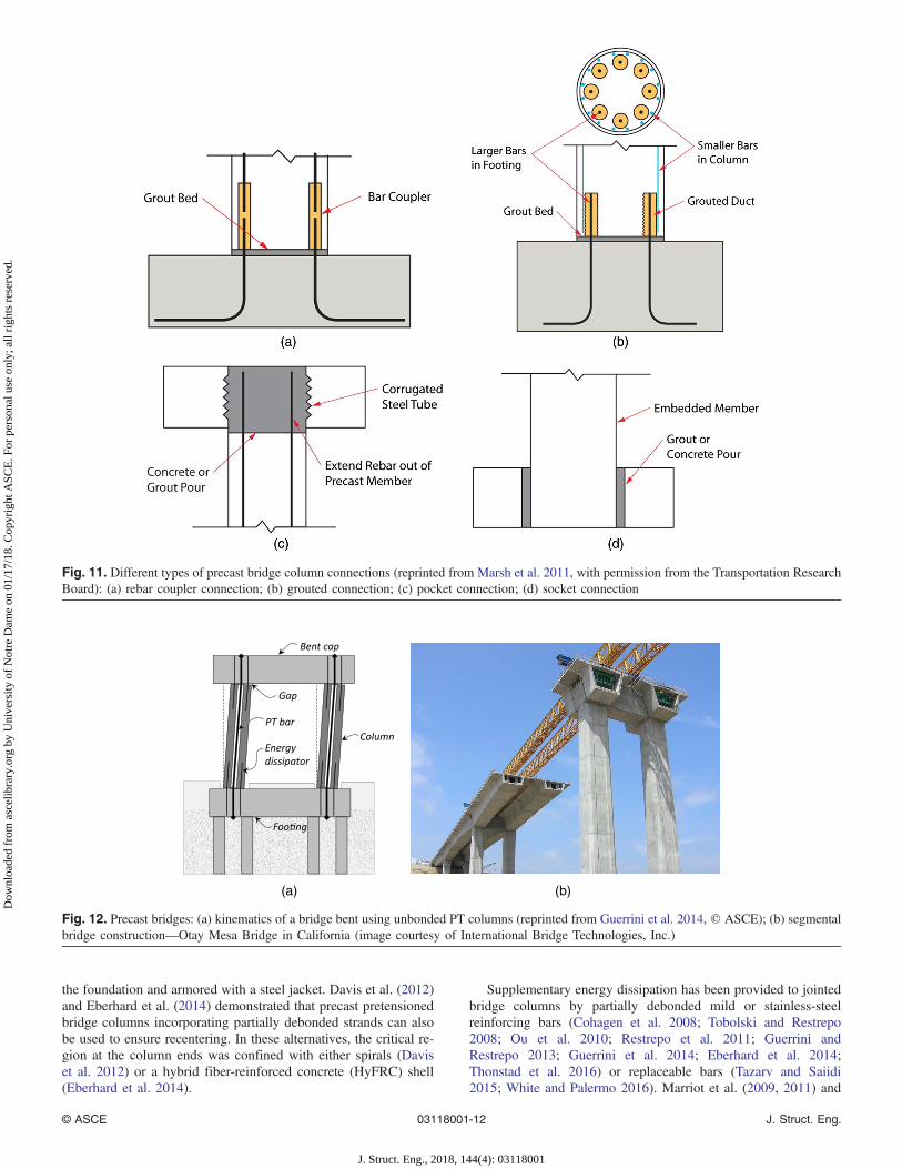
Bridge Columns
The preferred location of inelastic action in bridges is at the ends ofcolumns or piers, thereby minimizing damage to the superstructureand foundation, and making the inspection and repair of damagerelated to inelastic action easier. In emulative construction, thecolumns can be connected to precast or cast-in-place bent capsand foundations through reinforcing bar couplers, grouted ducts,pockets, and sockets (Fig. 11). Socketed connections can allowthe entire precast column to be embedded in the cap beam orfoundation (Osanai et al. 1996; Haraldsson et al. 2013; Mashalet al. 2013; Torres Matos and Rodriguez 2014; Belleri and Riva
2012), or with the column longitudinal bars developed in a pre-formed pocket (Restrepo et al. 2011). Emulative connections withcolumn bars developed in grouted ducts in the cap beam or foun-dation have been reported by Pang et al. (2009), Restrepo et al.(2011), and Tazarv and Saiidi (2015). Bridge column-to-cap-beamor column-to-foundation connections using grouted splice sleeves(Ameli et al. 2015) and mechanical splices (Haber et al. 2014) havealso been investigated.
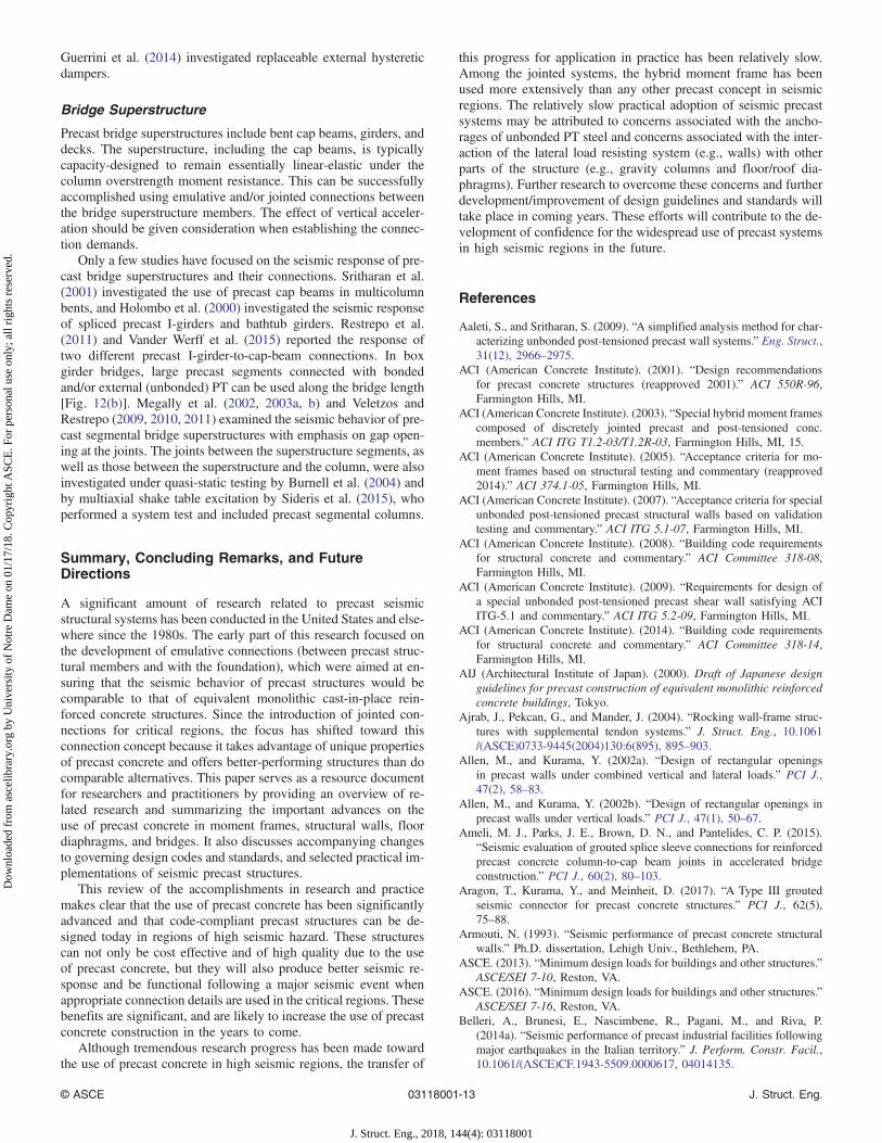
The jointed concept, as demonstrated for building frames andwalls using unbonded or partially debonded PT, has also been inves-tigated for bridge columns. The gap opening and large concentratedrotations previously described can occur at the column-to-foundation and column-to-cap-beam joints, promoting recenteringresponse for columnswhen subjected to seismic loading [Fig. 12(a)].
In most studies discussed in the literature, the column is pre-cast over the entire clear height and connected to the adjoiningmember(s) using unbonded PT. As in buildings, special detailsare used to avoid or minimize damage at the column-to-foundationand column-to-cap-beam joints and in the adjacent column criticalregions. To this end, Mander and Cheng (1997) investigated steelplates at the column-to-foundation joint. Palermo et al. (2007) in-cluded steel plates at the top of the foundation and armored thecolumn toes with steel angles. To ensure satisfactory shear transfer,they connected a hemispherical steel block to the steel plate.Tobolski and Restrepo (2008), Cohagen et al. (2008), Restrepoet al. (2011), Guerrini and Restrepo (2013), and Guerrini et al.(2014) investigated the types of bedding mortar that can withstandthe impact and transfer shear at the joint between the column andthe cap beam. Tobolski and Restrepo (2008) and Cohagen et al.(2008) used spirals with a small pitch to confine the column ends.Billington and Yoon (2004), Trono et al. (2014), and Tazarv andSaiidi (2015) replaced the column ends with a fiber-reinforced con-crete shell, left hollow or filled with self-consolidating concrete.Tobolski and Restrepo (2008), Restrepo et al. (2011), Guerriniand Restrepo (2013), and Guerrini et al. (2014) investigated col-umns built with a dual steel shell (with concrete cast in betweenthe shells) designed for composite action. Guerrini and Restrepo(2013), Guerrini et al. (2014), and Trono et al. (2014) used headedreinforcing bars at the column end with matching headed bars em-bedded in the foundation to transfer compression. ElGawady andSha’lan (2010) used thin neoprene pads at the column ends andfound that the sheets significantly reduced the lateral stiffness ofthe column. Motaref et al. (2014) used a laminated elastomericbearing at the column ends, where typically a plastic hinge woulddevelop in a conventional column. The use of these materials willalter the dynamic characteristics of the column, which should begiven attention in determining the expected response. Furthermore,because these materials are Voigt-type, the strain rate effect may besignificant and should be included when determining the dynamicresponse of the column.
Large columns or columns where the lifting capacity is limitedcan be segmented and then posttensioned using unbonded tendons.Hewes and Priestley (2002), Billington and Yoon (2004), Chou andChen (2006), Shim et al. (2008), Wang et al. (2008), Ou et al. (2007,2009, 2010), Taira et al. (2009), Yamashita and Sanders (2009),Sakai et al. (2009), Kim et al. (2010a, b, 2012), Motaref et al.(2014), and Dawood et al. (2012) investigated the response of pre-cast segmental columns where all joints could undergo gap opening,allowing the column to rock, while preventing (or minimizing) shearsliding. Sideris et al. (2014b, 2015) investigated a precast segmentalmethod where nonlinear deformations could occur either due torocking or through sliding.
Mashal and Palermo (2015) and White and Palermo (2016) in-vestigated unbonded PT bridge columns embedded in a socket in
© ASCE 03118001-11 J. Struct. Eng.
J. Struct. Eng., 2018, 144(4): 03118001
Dow
nloa
ded
from
asc
elib
rary
.org
by
Uni
vers
ity o
f N
otre
Dam
e on
01/
17/1
8. C
opyr
ight
ASC
E. F
or p
erso
nal u
se o
nly;
all
righ
ts r
eser
ved.
the foundation and armored with a steel jacket. Davis et al. (2012)and Eberhard et al. (2014) demonstrated that precast pretensionedbridge columns incorporating partially debonded strands can alsobe used to ensure recentering. In these alternatives, the critical re-gion at the column ends was confined with either spirals (Daviset al. 2012) or a hybrid fiber-reinforced concrete (HyFRC) shell(Eberhard et al. 2014).
Supplementary energy dissipation has been provided to jointedbridge columns by partially debonded mild or stainless-steelreinforcing bars (Cohagen et al. 2008; Tobolski and Restrepo2008; Ou et al. 2010; Restrepo et al. 2011; Guerrini andRestrepo 2013; Guerrini et al. 2014; Eberhard et al. 2014;Thonstad et al. 2016) or replaceable bars (Tazarv and Saiidi2015; White and Palermo 2016). Marriot et al. (2009, 2011) and
(a) (b)
Fig. 12. Precast bridges: (a) kinematics of a bridge bent using unbonded PT columns (reprinted from Guerrini et al. 2014, © ASCE); (b) segmentalbridge construction—Otay Mesa Bridge in California (image courtesy of International Bridge Technologies, Inc.)
Fig. 11. Different types of precast bridge column connections (reprinted from Marsh et al. 2011, with permission from the Transportation ResearchBoard): (a) rebar coupler connection; (b) grouted connection; (c) pocket connection; (d) socket connection
© ASCE 03118001-12 J. Struct. Eng.
J. Struct. Eng., 2018, 144(4): 03118001
Dow
nloa
ded
from
asc
elib
rary
.org
by
Uni
vers
ity o
f N
otre
Dam
e on
01/
17/1
8. C
opyr
ight
ASC
E. F
or p
erso
nal u
se o
nly;
all
righ
ts r
eser
ved.
Guerrini et al. (2014) investigated replaceable external hystereticdampers.
Bridge Superstructure
Precast bridge superstructures include bent cap beams, girders, anddecks. The superstructure, including the cap beams, is typicallycapacity-designed to remain essentially linear-elastic under thecolumn overstrength moment resistance. This can be successfullyaccomplished using emulative and/or jointed connections betweenthe bridge superstructure members. The effect of vertical acceler-ation should be given consideration when establishing the connec-tion demands.
Only a few studies have focused on the seismic response of pre-cast bridge superstructures and their connections. Sritharan et al.(2001) investigated the use of precast cap beams in multicolumnbents, and Holombo et al. (2000) investigated the seismic responseof spliced precast I-girders and bathtub girders. Restrepo et al.(2011) and Vander Werff et al. (2015) reported the response oftwo different precast I-girder-to-cap-beam connections. In boxgirder bridges, large precast segments connected with bondedand/or external (unbonded) PT can be used along the bridge length[Fig. 12(b)]. Megally et al. (2002, 2003a, b) and Veletzos andRestrepo (2009, 2010, 2011) examined the seismic behavior of pre-cast segmental bridge superstructures with emphasis on gap open-ing at the joints. The joints between the superstructure segments, aswell as those between the superstructure and the column, were alsoinvestigated under quasi-static testing by Burnell et al. (2004) andby multiaxial shake table excitation by Sideris et al. (2015), whoperformed a system test and included precast segmental columns.
Summary, Concluding Remarks, and FutureDirections
A significant amount of research related to precast seismicstructural systems has been conducted in the United States and else-where since the 1980s. The early part of this research focused onthe development of emulative connections (between precast struc-tural members and with the foundation), which were aimed at en-suring that the seismic behavior of precast structures would becomparable to that of equivalent monolithic cast-in-place rein-forced concrete structures. Since the introduction of jointed con-nections for critical regions, the focus has shifted toward thisconnection concept because it takes advantage of unique propertiesof precast concrete and offers better-performing structures than docomparable alternatives. This paper serves as a resource documentfor researchers and practitioners by providing an overview of re-lated research and summarizing the important advances on theuse of precast concrete in moment frames, structural walls, floordiaphragms, and bridges. It also discusses accompanying changesto governing design codes and standards, and selected practical im-plementations of seismic precast structures.
This review of the accomplishments in research and practicemakes clear that the use of precast concrete has been significantlyadvanced and that code-compliant precast structures can be de-signed today in regions of high seismic hazard. These structurescan not only be cost effective and of high quality due to the useof precast concrete, but they will also produce better seismic re-sponse and be functional following a major seismic event whenappropriate connection details are used in the critical regions. Thesebenefits are significant, and are likely to increase the use of precastconcrete construction in the years to come.
Although tremendous research progress has been made towardthe use of precast concrete in high seismic regions, the transfer of
this progress for application in practice has been relatively slow.Among the jointed systems, the hybrid moment frame has beenused more extensively than any other precast concept in seismicregions. The relatively slow practical adoption of seismic precastsystems may be attributed to concerns associated with the ancho-rages of unbonded PT steel and concerns associated with the inter-action of the lateral load resisting system (e.g., walls) with otherparts of the structure (e.g., gravity columns and floor/roof dia-phragms). Further research to overcome these concerns and furtherdevelopment/improvement of design guidelines and standards willtake place in coming years. These efforts will contribute to the de-velopment of confidence for the widespread use of precast systemsin high seismic regions in the future.
References
Aaleti, S., and Sritharan, S. (2009). “A simplified analysis method for char-acterizing unbonded post-tensioned precast wall systems.” Eng. Struct.,31(12), 2966–2975.
ACI (American Concrete Institute). (2001). “Design recommendationsfor precast concrete structures (reapproved 2001).” ACI 550R-96,Farmington Hills, MI.
ACI (American Concrete Institute). (2003). “Special hybrid moment framescomposed of discretely jointed precast and post-tensioned conc.members.” ACI ITG T1.2-03/T1.2R-03, Farmington Hills, MI, 15.
ACI (American Concrete Institute). (2005). “Acceptance criteria for mo-ment frames based on structural testing and commentary (reapproved2014).” ACI 374.1-05, Farmington Hills, MI.
ACI (American Concrete Institute). (2007). “Acceptance criteria for specialunbonded post-tensioned precast structural walls based on validationtesting and commentary.” ACI ITG 5.1-07, Farmington Hills, MI.
ACI (American Concrete Institute). (2008). “Building code requirementsfor structural concrete and commentary.” ACI Committee 318-08,Farmington Hills, MI.
ACI (American Concrete Institute). (2009). “Requirements for design ofa special unbonded post-tensioned precast shear wall satisfying ACIITG-5.1 and commentary.” ACI ITG 5.2-09, Farmington Hills, MI.
ACI (American Concrete Institute). (2014). “Building code requirementsfor structural concrete and commentary.” ACI Committee 318-14,Farmington Hills, MI.
AIJ (Architectural Institute of Japan). (2000). Draft of Japanese designguidelines for precast construction of equivalent monolithic reinforcedconcrete buildings, Tokyo.
Ajrab, J., Pekcan, G., and Mander, J. (2004). “Rocking wall-frame struc-tures with supplemental tendon systems.” J. Struct. Eng., 10.1061/(ASCE)0733-9445(2004)130:6(895), 895–903.
Allen, M., and Kurama, Y. (2002a). “Design of rectangular openingsin precast walls under combined vertical and lateral loads.” PCI J.,47(2), 58–83.
Allen, M., and Kurama, Y. (2002b). “Design of rectangular openings inprecast walls under vertical loads.” PCI J., 47(1), 50–67.
Ameli, M. J., Parks, J. E., Brown, D. N., and Pantelides, C. P. (2015).“Seismic evaluation of grouted splice sleeve connections for reinforcedprecast concrete column-to-cap beam joints in accelerated bridgeconstruction.” PCI J., 60(2), 80–103.
Aragon, T., Kurama, Y., and Meinheit, D. (2017). “A Type III groutedseismic connector for precast concrete structures.” PCI J., 62(5),75–88.
Armouti, N. (1993). “Seismic performance of precast concrete structuralwalls.” Ph.D. dissertation, Lehigh Univ., Bethlehem, PA.
ASCE. (2013). “Minimum design loads for buildings and other structures.”ASCE/SEI 7-10, Reston, VA.
ASCE. (2016). “Minimum design loads for buildings and other structures.”ASCE/SEI 7-16, Reston, VA.
Belleri, A., Brunesi, E., Nascimbene, R., Pagani, M., and Riva, P.(2014a). “Seismic performance of precast industrial facilities followingmajor earthquakes in the Italian territory.” J. Perform. Constr. Facil.,10.1061/(ASCE)CF.1943-5509.0000617, 04014135.
© ASCE 03118001-13 J. Struct. Eng.
J. Struct. Eng., 2018, 144(4): 03118001
Dow
nloa
ded
from
asc
elib
rary
.org
by
Uni
vers
ity o
f N
otre
Dam
e on
01/
17/1
8. C
opyr
ight
ASC
E. F
or p
erso
nal u
se o
nly;
all
righ
ts r
eser
ved.

Belleri, A., and Riva, P. (2012). “Seismic performance and retrofit of pre-cast concrete grouted sleeve connections.” PCI J., 57(1), 97–109.
Belleri, A., Schoettler, M. J., Restrepo, J. I., and Fleischman, R. B. (2014b).“Dynamic behavior of rocking and hybrid cantilever walls in a precastconcrete building.” ACI Struct. J., 111(3), 661.
Billington, S., and Yoon, J. (2004). “Cyclic response of unbonded post-tensioned precast columns with ductile fiber-reinforced concrete.”J. Bridge Eng., 10.1061/(ASCE)1084-0702(2004)9:4(353), 353–363.
Blandon, J. J., and Rodríguez, M. E. (2005). “Behavior of connectionsand floor diaphragms in seismic-resisting precast concrete buildings.”PCI J., 50(2), 56–75.
Bockemohle, L. W. (1981). “A practical paper on design of topped concretediaphragms and precast concrete structures.” Workshop on Design ofPrefabricated Concrete Buildings for Earthquake Loads, AppliedTechnology Council, Redwood City, CA.
Bournas, D. A., Negro, P., and Molina, F. J. (2013). “Pseudodynamic testson a full-scale 3-storey precast concrete building: Behavior of themechanical connections and floor diaphragms.” Eng. Struct., 57,609–627.
BSSC (Building Seismic Safety Council). (2001). NEHRP recommendedprovisions for seismic regulations for new buildings and other struc-tures, Washington, DC.
BSSC (Building Seismic Safety Council). (2009). Seismic design method-ology for precast concrete floor diaphragms, Washington, DC.
BSSC (Building Seismic Safety Council). (2015). NEHRP recommendedseismic provisions for new buildings and other structures, Washington,DC.
Bull, D. K. (2004). “Understanding the complexities of designing dia-phragms in buildings for earthquakes.” Bull. N. Z. Soc. EarthquakeEng., 37(2), 70–88.
Burnell, K., Restrepo, J. I., and Megally, S. (2004). “Longitudinal testingof a precast post-tensioned bridge system.” 20th US-Japan Workshopon Bridge Engineering, Public Works Research Institute of Japan,Washington, DC.
CAE (Centre for Advanced Engineering). (1999). Guidelines for the use ofstructural precast concrete in buildings, Christchurch, New Zealand.
Caltrans. (2013). Seismic design criteria, version 1.7, California Dept. ofTransportation, Sacramento, CA.
Cao, L., and Naito, C. (2009). “Precast double-tee floor connectors. Part 2:Shear performance.” PCI J., 54(2), 97–115.
Cheok, G., and Lew, H. (1993). “Model precast concrete beam-to-columnconnections subject to cyclic loading.” PCI J., 38(4), 80–92.
Chou, C. C., and Chen, Y. C. (2006). “Cyclic tests of post-tensioned precastCFT segmental bridge columns with unbonded strands.” EarthquakeEng. Struct. Dyn., 35(2), 159–175.
Cleland, N. M., and Ghosh, S. K. (2002). “Untopped precast concrete dia-phragms in high-seismic applications.” PCI J., 47(6), 94–99.
Cleland, N. M., and Ghosh, S. K. (2012). Seismic design of precast/prestressed concrete structures, Precast/Prestressed Concrete Institute,Chicago.
Clough, D. P. (1982). “Considerations in the design and construction ofprecast concrete diaphragms for earthquake loads.” PCI J., 27(2),79–93.
Cohagen, L. S., Pang, J. B. K., Eberhard, M. O., and Stanton, J. F. (2008).“A precast concrete bridge bent designed to recenter after an earth-quake.” Rep. No. WA-RD 684.3, Washington State TransportationCenter, Seattle.
Corney, S. R., Henry, R. S., and Ingham, J. M. (2014a). “Performance ofprecast concrete floor systems during the 2010/2011 Canterbury earth-quake series.” Mag. Concr. Res., 66(11), 563–575.
Corney, S. R., Henry, R. S., and Ingham, J. M. (2014b). “Testing supportconnections of 400 hollow-core precast concrete floors.” 10th U.S.National Conf. on Earthquake Engineering, Earthquake EngineeringResearch Institute, Oakland, CA.
Crisafulli, F. J., Restrepo, J. I., and Park, R. (2002). “Seismic design oflightly reinforced precast concrete rectangular wall panels.” PCI J.,47(4), 104–121.
D’Arcy, T. J., Nasser, G. D., and Ghosh, S. K. (2003). “Building code pro-visions for precast/prestressed concrete: A brief history.” PCI J., 48(6),116–124.
Davies, G., Elliott, K. S., and Omar, W. (1990). “Horizontal diaphragmaction in precast concrete floors.” Struct. Eng., 68(2), 25–33.
Davis, P. M., Janes, T. M., Eberhard, M. O., and Stanton, J. F. (2012).“Unbonded pre-tensioned columns for bridges in seismic regions.”PEER Rep. 2012/04, Pacific Earthquake Engineering Research Center,Berkeley, CA.
Dawood, H., ElGawady, M., and Hewes, J. (2012). “Behavior of segmentalprecast posttensioned bridge piers under lateral loads.” J. Bridge Eng.,10.1061/(ASCE)BE.1943-5592.0000252, 735–746.
Dhakal, R. P., Peng, B. H. H., Fenwick, R. C., Carr, A. J., and Bull, D. K.(2014). “Cyclic loading test of reinforced concrete frame with precast-prestressed flooring system.” ACI Struct. J., 111(4), 777–788.
DSDMTG (Diaphragm Seismic DesignMethodology Task Group). (2014).“Development and design of untopped precast concrete diaphragmsystem for high seismic zones.” ⟨http://www.pankowfoundation.org/grants.cfm?grantid=1070⟩ (Feb. 16, 2014).
Eberhard, M. O., Stanton, J. F., Haraldsson, O. S., Finnsson, G., Davis,P. M., and Schoettler, M. J. (2014). “Development of a bridge bentsystem for rapid construction and enhanced seismic performance.”10th U.S. National Conf. on Earthquake Engineering, EarthquakeEngineering Research Institute, Oakland, CA.
EERI (Earthquake Engineering Research Institute). (1989). Armenia earth-quake reconnaissance report, Oakland, CA.
EERI (Earthquake Engineering Research Institute). (2010). “The El MayorCucapah, Baja California earthquake.” An EERI learning from earth-quakes reconnaissance report, J. Meneses, ed., Oakland, CA.
ElGawady, M. A., and Sha’lan, A. (2010). “Seismic behavior of self-centering precast segmental bridge bents.” J. Bridge Eng., 10.1061/(ASCE)BE.1943-5592.0000174, 328–339.
El-Sheikh, M. T., Sause, R., Pessiki, S., and Lu, L.-W. (1999). “Seismicbehavior and design of unbonded post-tensioned precast concreteframes.” PCI J., 44(3), 54–71.
Englekirk, R. (1986). “Overview of PCI workshop on effective use ofprecast concrete for seismic resistance.” PCI J., 31(6), 48–58.
Englekirk, R. (2002). “Design-construction of the paramount: A 39-storyprecast prestressed concrete apartment building.” PCI J., 47(4), 56–71.
Ericson, A. C., and Warnes, C. E. (1990). Seismic technology for precastconcrete systems, Concrete Industry Board, Inc., Kew Gardens, NY.
Erkmen, B., and Schultz, A. E. (2009). “Self-centering behavior of un-bonded, post-tensioned precast concrete shear walls.” J. EarthquakeEng., 13(7), 1047–1064.
Farrow, K. T., and Fleischman, R. B. (2003). “Effect of dimension and de-tail on the capacity of precast concrete parking structure diaphragms.”PCI J., 48(5), 46–61.
Farrow, K. T., and Kurama, Y. C. (2003). “SDOF demand index relation-ships for performance-based seismic design.” Earthquake Spectra,19(4), 799–838.
Fenwick, R., Bull, D., and Gardiner, D. (2010). “Assessment of hollow-core floors for seismic performance.” Rep. No. 2010-02, Univ. ofCanterbury, Christchurch, New Zealand.
Fenwick, R. C., Davidson, B. J., and Lau, D. B. N. (2005). “Interactionbetween ductile RC perimeter frames and floor slabs containing precastunits.” New Zealand Society for Earthquake Engineering Conf., NewZealand Society for Earthquake Engineering, Wellington, New Zealand.
fib (Fédération internationale du béton). (2003). Seismic design of precastconcrete buildings, Lausanne, Switzerland, 262.
fib (Fédération internationale du béton). (2016). Pre-cast concrete build-ings in seismic areas, Lausanne, Switzerland, 273.
Fleischman, R. B., et al. (2005a). “Seismic design methodology for pre-cast concrete diaphragms. Part 2: Research program.” PCI J., 51(6),2–19.
Fleischman, R. B., Farrow, K., and Eastman, K. (2002). “Seismic responseof perimeter lateral-system structures with highly flexible diaphragms.”Earthquake Spectra, 18(2), 251–286.
Fleischman, R. B., and Farrow, K. T. (2001). “Dynamic response of perime-ter lateral-system structures with flexible diaphragms.” EarthquakeEng. Struct. Dyn., 30(5), 745–763.
Fleischman, R. B., Naito, C. J., Restrepo, J., Sause, R., and Ghosh, S. K.(2005b). “Seismic design methodology for precast concrete diaphragmsPart 1: Design framework.” PCI J., 50(5), 68–83.
© ASCE 03118001-14 J. Struct. Eng.
J. Struct. Eng., 2018, 144(4): 03118001
Dow
nloa
ded
from
asc
elib
rary
.org
by
Uni
vers
ity o
f N
otre
Dam
e on
01/
17/1
8. C
opyr
ight
ASC
E. F
or p
erso
nal u
se o
nly;
all
righ
ts r
eser
ved.

Fleischman, R. B., Restrepo, J. I., Naito, C., Sause, R., Zhang, D., andSchoettler, M. (2013). “Integrated analytical and experimental researchto develop a new seismic design methodology for precast concrete dia-phragms.” J. Struct. Eng., 10.1061/(ASCE)ST.1943-541X.0000734,1192–1204.
Fleischman, R. B., Restrepo, J. I., Pampanin, S., Maffei, J. R., Seeber, K.,and Zahn, F. A. (2014). “Damage evaluations of precast concrete struc-tures in the 2010–2011 Canterbury earthquake sequence.” EarthquakeSpectra, 30(1), 277–306.
Fleischman, R. B., and Wan, G. (2007). “Appropriate overstrength of shearreinforcement in precast concrete diaphragms.” J. Struct. Eng., 10.1061/(ASCE)0733-9445(2007)133:11(1616), 1616–1626.
Galusha, J. G. (1999). “Precast, post-tensioned concrete walls designed torock.” M.S.C.E. thesis, Univ. of Washington, Seattle.
Gates, W. E. (1981). “Seismic design considering for untopped precastconcrete floor and roof diaphragm.” Workshop on Design of Prefabri-cated Concrete Buildings for Earthquake Loads, Applied TechnologyCouncil, Redwood City, CA.
Ghosh, S. K. (2004). “Update on the NEHRP provisions: The resourcedocument for seismic design.” PCI J., 49(3), 96–102.
Ghosh, S. K. (2016). “Alternative diaphragm seismic design force level ofASCE 7-16.” Structure Magazine, Mar., 18–23.
Ghosh, S. K., and Cleland, N. M. (2012). “Performance of precast concretebuilding structures.” Earthquake Spectra, 28(S1), S349–S384.
Guerrini, G., and Restrepo, J. (2013). “Seismic response of compositeconcrete-dual steel shell columns for accelerated bridge construction.”7th National Seismic Conf. on Bridges and Highways, State Univ. ofNew York, Buffalo, NY.
Guerrini, G., Restrepo, J. I., Massari, M., and Vervelidis, A. (2014).“Seismic behavior of posttensioned self-centering precast concretedual-shell steel columns.” J. Struct. Eng., 10.1061/(ASCE)ST.1943-541X.0001054, 04014115.
Haber, Z. B., Saiidi, M. S., and Sanders, D. H. (2014). “Seismic perfor-mance of precast columns with mechanically spliced column-footingconnections.” ACI Struct. J., 111(3), 639.
Haraldsson, O. S., Janes, T. M., Eberhard, M. O., and Stanton, J. F. (2013).“Seismic resistance of socket connection between footing and precastcolumn.” J. Bridge Eng., 10.1061/(ASCE)BE.1943-5592.0000413,910–919.
Hawkins, N. M., and Englekirk, R. (1987). “U.S.-Japan seminar on precastconcrete construction in seismic zones.” PCI J., 32(2), 75–85.
Hawkins, N. M., and Ghosh, S. K. (2004). “Acceptance criteria for specialprecast concrete structural walls based on validation testing.” PCI J.,49(5), 78–92.
Hawkins, N. M., and Ghosh, S. K. (2006). “Codification of precast seismicstructural systems: An update.” PCI J., 51(3), 46–49.
Henry, R. S., Brooke, N. J., Sritharan, S., and Ingham, J. M. (2012).“Defining concrete compressive strain in unbonded post-tensionedwalls.” ACI Struct. J., 109(1), 101–112.
Hewes, J. T., and Priestley, M. N. (2002). “Seismic design and performanceof precast concrete segmental bridge columns.” Rep. No. SSRP-2001/25,Univ. of California, San Diego.
Holden, T., Restrepo, J., and Mander, J. (2001). “A comparison of the seis-mic performance of precast wall construction: Emulation and hybridapproaches.” Rep. No. 2001-4, Univ. of Canterbury, Christchurch,New Zealand.
Holden, T., Restrepo, J., and Mander, J. B. (2003). “Seismic performanceof precast reinforced and prestressed concrete walls.” J. Struct. Eng.,10.1061/(ASCE)0733-9445(2003)129:3(286), 286–296.
Holombo, J. M., Priestley, J. N., and Seible, F. (2000). “Continuity of pre-cast prestressed spliced-girder bridges under seismic loads.” PCI J.,45(2), 40–63.
Housner, G. and Lili, X. (2002). The great Tangshan earthquake of 1976:Overview volume, G. W. Housner and H. Duxin, eds., EarthquakeEngineering Laboratory, California Institute of Technology, Pasadena,CA.
IBC (International Building Code). (2014). “2015 international buildingcode.” IBC-15, International Code Council, Country Club Hills, IL.
Iverson, J., and Hawkins, N. (1994). “Performance of precast/prestressedconcrete building structures during Northridge earthquake.” PCI J.,39(2), 38–55.
Jensen, J. (2006). “Experimental investigation of existing hollow-core seat-ing connections pre and post retrofit.”M.E. thesis, Univ. of Canterbury,Christchurch, New Zealand.
Kelly, D. J., and Ghosh, S. K. (2014). “Diaphragm response to and designfor earthquake ground motions.” 10th U.S. National Conf. onEarthquake Engineering, Earthquake Engineering Research Institute,Oakland, CA.
Kim, T.-H., Lee, H.-M., Kim, Y.-J., and Shin, H. M. (2010a). “Performanceassessment of precast concrete segmental bridge columns with a shearresistant connecting structure.” Eng. Struct., 32(5), 1292–1303.
Kim, T.-H., Park, S.-J., Kim, Y-J., and Shin, H. M. (2010b). “Performanceassessment of precast segmental PSC bridge columns with precast con-crete footings.” Mag. Concr. Res., 62(11), 773–787.
Kim, T.-H., Seong, D.-J., and Shin, H. M. (2012). “Seismic performanceassessment of hollow reinforced concrete and prestressed concretebridge columns.” Int. J. Concrete Struct. Mater., 6(3) 165–176.
Kurama, Y. (2000). “Seismic design of unbonded post-tensioned precastwalls with supplemental viscous damping.” ACI Struct. J., 97(4),648–658.
Kurama, Y. (2001). “Simplified seismic design approach for friction-damped unbonded post-tensioned precast walls.” ACI Struct. J.,98(5), 705–716.
Kurama, Y. (2002). “Hybrid post-tensioned precast concrete walls for use inseismic regions.” PCI J., 47(5), 36–59.
Kurama, Y. (2005). “Seismic design of partially post-tensioned precastconcrete walls.” PCI J., 50(4), 100–125.
Kurama, Y., Pessiki, S., Sause, R., and Lu, L. W. (1999a). “Seismic behav-ior and design of unbonded post-tensioned precast concrete walls.”PCI J., 44(3), 72–89.
Kurama, Y., Sause, R., Pessiki, S., and Lu, L. W. (1999b). “Lateral loadbehavior and seismic design of unbonded post-tensioned precast con-crete walls.” ACI Struct. J., 96(4), 622–632.
Kurama, Y., Sause, R., Pessiki, S., and Lu, L. W. (2002). “Seismic responseevaluation of unbonded post-tensioned precast walls.” ACI Struct. J.,99(5), 641–651.
Lee, H. J., Aschheim, M. A., and Kuchma, D. (2007). “Interstory drift es-timates for low-rise flexible diaphragm structures.” Eng. Struct., 29(7),1375–1397.
Lee, H. J., and Kuchma, D. A. (2008). “Seismic response of parking struc-tures with precast concrete diaphragms.” PCI J., 53(2), 71–94.
Liu, Q., Watkins, J., French, C., Sritharan, S., and Nakaki, S. (2015).Rocking wall-floor-column subassemblage pseudo-static cyclic test atNEES@UMN (MAST) specimen 2 [Data set], Network for EarthquakeEngineering Simulation, Austin, TX.
Mander, J. B., and Cheng, C-T. (1997). “Seismic resistance of bridge piersbased on damage avoidance design.” Technical Rep. NCEER-97-0014,State Univ. of New York, Buffalo, NY, 109.
Marriott, D., Pampanin, S., Bull, D., and Palermo, A. (2008). “Dynamictesting of precast, post-tensioned rocking wall systems with alter-native dissipating solutions.” Bull. N. Z. Soc. Earthquake Eng., 41(2),90–103.
Marriott, D., Pampanin, S., and Palermo, A. (2009). “Quasi-static andpseudo-dynamic testing of unbonded post-tensioned rocking bridgepiers with external replaceable dissipaters.” Earthquake Eng. Struct.Dyn., 38(3), 331–354.
Marriott, D., Pampanin, S., and Palermo, A. (2011). “Biaxial testing of un-bonded post-tensioned rocking bridge piers with external replaceabledissipaters.” Earthquake Eng. Struct. Dyn., 40(15), 1723–1741.
Marsh, M. L., Wernli, M., Garrett, B. E., Stanton, J. F., Eberhard, M. O.,and Weinert, M. D. (2011). “Application of accelerated bridge construc-tion connections in moderate-to-high seismic regions.” NCHRP Rep.698, Transportation Research Board of the National Academies,Washington, DC, 54.
Martin, L., and Korkosz, W. (1982). “Connections of precast prestressedconcrete buildings, including earthquake resistance.” Technical Rep.No. 2, Prestressed Concrete Institute, Chicago.
© ASCE 03118001-15 J. Struct. Eng.
J. Struct. Eng., 2018, 144(4): 03118001
Dow
nloa
ded
from
asc
elib
rary
.org
by
Uni
vers
ity o
f N
otre
Dam
e on
01/
17/1
8. C
opyr
ight
ASC
E. F
or p
erso
nal u
se o
nly;
all
righ
ts r
eser
ved.

Mashal, M., and Palermo, A. (2015). “High-damage and low-damageseismic design technologies for accelerated bridge construction.” ASCEStructures Congress, ASCE, Portland, OR, 549–560.
Mashal, M., White, S., and Palermo, A. (2013). “Quasi-static cyclic tests ofemulative precast segmental bridge piers (E-PSBP).” New ZealandSociety for Earthquake Engineering Conf., New Zealand Society forEarthquake Engineering, Wellington, New Zealand.
Matthews, J. (2004). “Hollow-core floor slab performance following asevere earthquake.” Ph.D. thesis, Univ. of Canterbury, Christchurch,New Zealand.
Megally, S., Seible, F., and Dowell, R. K. (2003a). “Seismic performance ofprecast segmental bridges: Segment-to-segment joints subjected to highflexural moments and high shears.” PCI J., 48(3), 72–90.
Megally, S., Seible, F., and Dowell, R. K. (2003b). “Seismic performanceof precast segmental bridges: Segment-to-segment joints subjected tohigh flexural moments and low shears.” PCI J., 48(2), 80–96.
Megally, S., Seible, F., Garg, M., and Dowell, R. K. (2002). “Seismic per-formance of precast segmental bridge superstructures with internallybonded prestressing tendons.” PCI J., 47(2), 40–56.
Mejia-McMaster, J. C., and Park, R. (1994). “Tests on special reinforce-ment for end support of hollow-core slabs.” PCI J., 39(5), 90–105.
Menegotto, M. (1994). “Seismic diaphragm behavior of untopped hollow-core floors.” 12th FIP Congress, Int. Federation for Prestressing,Federation Internationale de la Precontrainte, Lausanne, Switzerland,E3–E9.
Menegotto, M., Monti, G., and Auriccio, F. (1998). “Diaphragm modelingof precast floors with frictional joints.” 11th European Conf. on Earth-quake Engineering, Bogaziçi Univ., Istanbul, Turkey.
Moehle, J. P., Hooper, J., Kelly, D., and Meyer, T. (2010). “Seismic designof cast-in-place concrete diaphragms, chords, and collections.” NISTGCR 10-917-4, National Institute of Standards and Technology,Gaithersburg, MD.
Morgen, B., and Kurama, Y. (2004). “A friction damper for post-tensionedprecast concrete moment frames.” PCI J., 49(4), 112–133.
Morgen, B., and Kurama, Y. (2007). “Seismic design of friction-dampedprecast concrete frame structures.” J. Struct. Eng., 10.1061/(ASCE)0733-9445(2007)133:11(1501), 1501–1511.
Morgen, B., and Kurama, Y. (2008). “Seismic response evaluation of post-tensioned precast concrete frames with friction dampers.” J. Struct.Eng., 10.1061/(ASCE)0733-9445(2008)134:1(132), 132–145.
Motaref, S., Saiidi, M. S., and Sanders, D. (2014). “Shake table studies ofenergy-dissipating segmental bridge columns.” J. Bridge Eng., 10.1061/(ASCE)BE.1943-5592.0000518, 186–199.
Moustafa, S. E. (1981). “Effectiveness of shear-friction reinforcementin shear diaphragm capacity of hollow-core slabs.” PCI J., 26(1),118–133.
Muguruma, H., Nishiyama, M., and Watanabe, F. (1995). “Lessons fromthe Kobe earthquake: A Japanese perspective.” PCI J., 40(4), 28–42.
Muir, C. A., Bull, D. K., and Pampanin, S. (2012). “Preliminary observa-tions from biaxial testing of a two-storey, two-by-one bay, reinforcedconcrete slotted beam superassembly.” Bull. N. Z. Soc. EarthquakeEng., 45(3), 97–104.
Musselman, E., Fournier, M., McAlpine, P., and Sritharan, S. (2015).“Behavior of unbonded post-tensioning monostrand anchorage systemsunder short duration, high amplitude cyclical loading.” Eng. Struct.,104, 116–125.
Nagae, T., et al. (2014). “The 2010 E-defense shaking table test on four-story reinforced concrete and post-tensioned concrete buildings.”10th U.S. National Conf. on Earthquake Engineering: Frontiers ofEarthquake Engineering, Earthquake Engineering Research Institute,Oakland, CA.
Naito, C. (2016). “In-plane qualification of the meadow burke seismicchord connector.” ATLSS Rep. No. 16-02, Lehigh Univ., Bethlehem,PA, 22.
Naito, C., Cao, L., and Peter, W. (2009). “Precast double-tee floor connec-tions. Part 1: Tension performance.” PCI J., 54(1), 49–66.
Naito, C., Jones, C., Cullen, T., and Ren, R. (2007). “Development of aseismic design methodology for precast diaphragms—Phase 1b sum-mary report.” ATLSS Rep., Lehigh Univ., Bethlehem, PA.
Naito, C., Peter, W., and Cao, L. (2006). “Development of a seismic designmethodology for precast diaphragms—Phase 1 summary report.”ATLSS Rep. No. 06-01, Lehigh Univ., Bethlehem, PA.
Naito, C., and Ren, R. (2013). “An evaluation method for precast concretediaphragm connectors based on structural testing.” PCI J., 58(2),106–118.
Nakaki, S. D. (2000). “Design guidelines for precast and cast-in-place con-crete diaphragms.” Technical Rep., Earthquake Engineering ResearchInstitute, Oakland, CA.
Nakaki, S. D., Stanton, J., and Sritharan, S. (1999). “An overview of thePRESSS five-story precast test building.” PCI J., 44(2), 26–39.
Nazari, M., Sritharan, S., and Aaleti, A. (2017). “Single precast concreterocking walls as earthquake force-resisting elements.” Earthquake Eng.Struct. Dyn., 46(5), 753–769.
Negro, P., Bournas, D. A., and Molina, F. J. (2013). “Pseudodynamic testson a full-scale 3-storey precast concrete building: Global response.”Eng. Struct., 57, 594–608.
Nishiyama, M. (1990). “Seismic design of prestressed concrete buildings.”Bull. N. Z. Natl. Soc. Earthquake Eng., 23(4), 288–304.
Oliva, M. (2000). Testing of the JVI flange connector for precast concretedouble-tee system, Univ. of Wisconsin, Madison, WI.
Oliva, M., Clough, R., and Malhas, F. (1989). “Seismic behavior of largepanel precast concrete walls: Analysis and experiment.” PCI J., 34(5),42–66.
Oliva, M., Gavrilovic, P., and Clough, R. (1990). “Seismic testing of largepanel precast walls: Comparison of pseudostatic and shaking tabletests.” Earthquake Eng. Struct. Dyn., 19(6), 859–875.
Osanai, Y., Watanabe, F., and Okamoto, S. (1996). “Stress transfer mecha-nism of socket base connections with precast concrete columns.”ACI Struct. J., 93(3), 266–276.
Ou, Y. C., Chiewanichakorn, M., Aref, A. J., and Lee, G. C. (2007).“Seismic performance of segmental precast unbonded posttensionedconcrete bridge columns.” J. Struct. Eng., 10.1061/(ASCE)0733-9445(2007)133:11(1636), 1636–1647.
Ou, Y. C., Tsai, M. S., Chang, K. C., and Lee, G. C. (2010). “Cyclic behav-ior of precast segmental concrete bridge columns with high perfor-mance or conventional steel reinforcing bars as energy dissipationbars.” Earthquake Eng. Struct. Dyn., 39(11), 1181–1198.
Ou, Y. C., Wang, P. H., Tsai, M. S., Chang, K. C., and Lee, G. C. (2009).“Large-scale experimental study of precast segmental unbonded post-tensioned concrete bridge columns for seismic regions.” J. Struct. Eng.,10.1061/(ASCE)ST.1943-541X.0000110, 255–264.
Palermo, A., Pampanin, S., and Marriott, D. (2007). “Design, modeling,and experimental response of seismic resistant bridge piers with post-tensioned dissipating connections.” J. Struct. Eng., 10.1061/(ASCE)0733-9445(2007)133:11(1648), 1648–1661.
Pampanin, S., Kam, W. Y., Haverland, G., and Gardiner, S. (2011).“Expectation meets reality: Seismic performance of a post-tensionedprecast concrete building (PRESSS technology) during the 22nd Feb2011 Christchurch Earthquake.” New Zealand Concrete Industry Conf.,New Zealand Concrete Society, Auckland, New Zealand.
Pampanin, S., Marriott, D., and Palermo, A. (2010). PRESSS design hand-book, New Zealand Concrete Society, Auckland, New Zealand.
Pang, J. B., Eberhard, M. O., and Stanton, J. F. (2009). “Large-bar connec-tion for precast bridge bents in seismic regions.” J. Bridge Eng.,10.1061/(ASCE)BE.1943-5592.0000081, 231–239.
Pang, R., Liang, S., and Zhu, X. (2012). “Experimental study on seismicbehavior of slab connections in untopped precast RC floor diaphragms.”J. Build. Struct., 33(10), 59–66.
Park, R. (1990). “Precast concrete in seismic resisting buildings inNew Zealand.” Concr. Int., 12(11), 43–51.
Park, R. (1995). “A perspective on the seismic design of precast concretestructures in New Zealand.” PCI J., 40(3), 40–60.
Park, R., and Bull, D. K. (1986). “Seismic resistance of frames incorporat-ing precast prestressed concrete beam shells.” PCI J., 31(4), 54–93.
PCI (Precast/Prestressed Concrete Institute). (2010). PCI design handbook,7th Ed., Chicago.
Perez, F., Pessiki, S., and Sause, R. (2004a). “Lateral load behavior ofunbonded post-tensioned precast concrete walls with vertical joints.”PCI J., 49(2), 48–64.
© ASCE 03118001-16 J. Struct. Eng.
J. Struct. Eng., 2018, 144(4): 03118001
Dow
nloa
ded
from
asc
elib
rary
.org
by
Uni
vers
ity o
f N
otre
Dam
e on
01/
17/1
8. C
opyr
ight
ASC
E. F
or p
erso
nal u
se o
nly;
all
righ
ts r
eser
ved.
Perez, F., Pessiki, S., and Sause, R. (2004b). “Seismic design of unbondedpost-tensioned precast concrete walls with vertical joint connectors.”PCI J., 49(1), 58–79.
Perez, F. J., Pessiki, S., and Sause, R. (2013). “Experimental lateral loadresponse of unbonded post-tensioned precast concrete walls.” ACIStruct. J., 110(6), 1045–1055.
Perez, F. J., Sause, R., and Pessiki, S. (2007). “Analytical and experimentallateral load behavior of unbonded posttensioned precast concretewalls.” J. Struct. Eng., 10.1061/(ASCE)0733-9445(2007)133:11(1531),1531–1540.
Pincheira, J. A., Oliva, M. G., and Kusumo-Rahardjo, F. I. (1998). “Testson double tee flange connectors subjected to monotonic and cyclicloading.” PCI J., 43(3), 82–96.
Priestley, M. (1991). “Overview of PRESSS research program.” PCI J.,36(4), 50–57.
Priestley, M., Sritharan, S., Conley, J., and Pampanin, S. (1999). “Prelimi-nary results and conclusions from the PRESSS five-story precast con-crete test building.” PCI J., 44(6), 42–67.
Priestley, M., and Tao, J. (1993). “Seismic response of precast prestressedconcrete frames with partially debonded tendons.” PCI J., 38(1), 58–69.
Psycharis, I. N., and Mouzakis, H. P. (2012). “Shear resistance of pinnedconnections of precast members to monotonic and cyclic loading.”Eng. Struct., 41, 413–427.
PTI (Post-Tensioning Institute). (2006). Post-tensioning manual, 6th Ed.,Farmington Hills, MI.
Rahman, A., and Restrepo, J. (2000). “Earthquake resistant precast con-crete buildings: Seismic performance of cantilever walls prestressedusing unbonded tendons.” Rep. No. 2000-5, Univ. of Canterbury,Christchurch, New Zealand.
Rahman, M. A., and Sritharan, S. (2015). “Seismic response of precast,posttensioned concrete jointed wall systems designed for low- to mid-rise buildings using the direct displacement-based approach.” PCI J.,60(2), 38–56.
Ren, R., and Naito, C. (2013). “Precast concrete diaphragm connector per-formance database.” J. Struct. Eng., 10.1061/(ASCE)ST.1943-541X.0000598, 15–27.
Restrepo, J. I. (2003). “Self-centering precast post-tensioned cantileverwalls: Theory and experimental work.” Structures Congress, ASCE,Seattle.
Restrepo, J. I., Park, R., and Buchanan, A. H. (1995). “Tests on connectionsof earthquake resisting precast reinforced concrete perimeter frames ofbuildings.” PCI J., 40(4), 44–61.
Restrepo, J. I., and Rahman, A. (2007). “Seismic performance of self-centering structural walls incorporating energy dissipators.” J. Struct.Eng., 10.1061/(ASCE)0733-9445(2007)133:11(1560), 1560–1570.
Restrepo, J. I., Tobolski, M. J., and Matsumoto, E. E. (2011). “Develop-ment of a precast bent cap system for seismic regions.” NCHRP Rep.681, Transportation Research Board, Washington, DC, 106.
Rodriguez, M., Restrepo, J. I., and Blandon, J. J. (2007). “Seismic designforces of rigid floor diaphragms in precast concrete building struc-tures.” J. Struct. Eng., 10.1061/(ASCE)0733-9445(2007)133:11(1604),1604–1615.
Rodriguez, M., Restrepo, J. I., and Carr, A. J. (2002). “Earthquake inducedfloor horizontal accelerations in buildings.” Earthquake Eng. Struct.Dyn., 31(3), 693–718.
Saatcioglu, M., et al. (2001). “The August 17, 1999, Kocaeli (Turkey)earthquake—Damage to structures.” Can. J. Civ. Eng., 28(4),715–737.
Sakai, J., Unjoh, S., and Hoshikuma, J. (2009). “Development of seismicdesign method for precast segmental concrete bridge column.” Techni-cal Rep. MCEER-09-0012, Multidisciplinary Center for EarthquakeEngineering Research, Buffalo, NY.
Schoettler, M. J., Belleri, A., Zhang, D., Restrepo, J., and Fleischman, R. B.(2009). “Preliminary results of the shake-table testing for developmentof a diaphragm seismic design methodology.” PCI J., 54(1), 100–124.
Seeber, K. (2014). “The future use of PC in China.” Technical Presenta-tion, Southeast Univ., Nanjing, P.R. China.
Seifi, P., Henry, R. S., and Ingham, J. M. (2016). “Panel connection detailsin existing New Zealand precast concrete buildings.” Bull. N. Z. Soc.Earthquake Eng., 49(2), 190–199.
Seifi, P., Henry, R. S., and Ingham, J. M. (2017). “In-plane testing ofprecast concrete walls with grouted connections.” 16th World Conf.in Earthquake Engineering, International Association of EarthquakeEngineering, Tokyo.
Seo, C., and Sause, R. (2005). “Ductility demands on self-centeringsystems under earthquake loading.” ACI Struct. J., 102(2), 275–285.
Shaikh, A. F., and Feile, E. P. (2004). “Load testing of a precast concretedouble-tee flange connector.” PCI J., 49(3), 85–94.
Shim, C. S., Chung, C. S., and Kim, H. H. (2008). “Experimental evalu-ation of seismic performance of precast segmental bridge piers with acircular solid section.” Eng. Struct., 30(12), 3782–3792.
Shutt, C. A. (1997). “Hybrid precast frame meets seismic challenges.”Ascent, Spring, 14–19.
Sideris, P., Aref, A. J., and Filiatrault, A. (2014a). “Effects of anchoragehardware on the cyclic tensile response of unbonded monostrands.”PCI J., 59(3), 60–77.
Sideris, P., Aref, A. J., and Filiatrault, A. (2014b). “Large-scale seismictesting of a hybrid sliding-rocking posttensioned segmental bridgesystem.” J. Struct. Eng., 10.1061/(ASCE)ST.1943-541X.0000961,04014025.
Sideris, P., Aref, A. J., and Filiatrault, A. (2015). “Experimental seismicperformance of a hybrid sliding: Rocking bridge for various specimenconfigurations and seismic loading conditions.” J. Bridge Eng., 10.1061/(ASCE)BE.1943-5592.0000742, 04015009.
Smith, B., and Kurama, Y. (2014). “Seismic design guidelines for solid andperforated hybrid precast concrete shear walls.” PCI J., 59(3), 43–59.
Smith, B., Kurama, Y., and McGinnis, M. (2011). “Design and measuredbehavior of a hybrid precast concrete wall specimen for seismicregions.” J. Struct. Eng., 10.1061/(ASCE)ST.1943-541X.0000327,1052–1062.
Smith, B., Kurama, Y., and McGinnis, M. (2013). “Behavior of precastconcrete shear walls for seismic regions: Comparison of hybrid and em-ulative specimens.” J. Struct. Eng., 10.1061/(ASCE)ST.1943-541X.0000755, 1917–1927.
Smith, B., Kurama, Y., and McGinnis, M. (2015). “Perforated hybrid pre-cast shear walls for seismic regions.” ACI Struct. J., 112(3), 359–370.
Sritharan, S. (2002). “Performance of four jointed precast frame systemsunder simulated seismic loading.” 7th U.S. National Conf. on Earth-quake Engineering, Earthquake Engineering Research Institute,Oakland, CA.
Sritharan, S., Aaleti, S., Henry, R. S., Liu, K. Y., and Tsai, K. C. (2015).“Precast concrete wall with end columns (PreWEC) for earthquakeresistant design.” Earthquake Eng. Struct. Dyn., 44(12), 2075–2092.
Sritharan, S., Priestley, M. J. N., and Seible, F. (2001). “Seismic design andexperimental verification of concrete multiple column bridge bents.”ACI Struct. J., 98(3):335–346.
Standards New Zealand. (2004). “Structural design actions. Part 5:Earthquake actions—New Zealand.” NZS 1170.5, Wellington,New Zealand.
Standards New Zealand. (2006). “Concrete structures standard:Amendment 2.” NZS 3101, Wellington, New Zealand.
Stone, W. C., Cheok, G. S., and Stanton, J. F. (1995). “Performance ofhybrid moment-resisting precast beam-column concrete connectionssubjected to cyclic loading.” ACI Struct. J., 92(2), 229–249.
Taira, Y., Sakai, J., and Hoshikuma, J. (2009). “A study on restorable pre-cast and prestressed hybrid piers.” Technical Rep. MCEER-09-0012,Multidisciplinary Center for Earthquake Engineering Research,Buffalo, NY.
Tazarv, M., and Saiidi, M. (2015). “UHPC-filled duct connections for ac-celerated bridge construction of RC columns in high seismic zones.”Eng. Struct., 99, 413–422.
Thonstad, T., Mantawy, I. M., Stanton, J. F., Eberhard, M. O., and Sanders,D. H. (2016). “Shaking table performance of a new bridge system withpretensioned rocking columns.” J. Bridge Eng., 10.1061/(ASCE)BE.1943-5592.0000867, 04015079.
Tobolski, M. J., and Restrepo, J. I. (2008). “Development of rocking col-umn systems.” 6th National Seismic Conf. on Bridges and Highways,M. Keever and L. Mesa, eds., Univ. at Buffalo, Buffalo, NY.
© ASCE 03118001-17 J. Struct. Eng.
J. Struct. Eng., 2018, 144(4): 03118001
Dow
nloa
ded
from
asc
elib
rary
.org
by
Uni
vers
ity o
f N
otre
Dam
e on
01/
17/1
8. C
opyr
ight
ASC
E. F
or p
erso
nal u
se o
nly;
all
righ
ts r
eser
ved.
Toniolo, G., and Colombo, A. (2012). “Precast concrete structures: Thelessons learned from the L’Aquila earthquake.” Struct. Concr., 13(2),73–83.
Torres Matos, M. Y., and Rodriguez, M. (2014). “Comportamiento Sísmicode Cimentacion Tipo Candelero para Puentes Con Columnas Prefabri-cadas de Concreto Reforzado.” Revista de Ingenieria Sísmica, 90,55–87 (in Spanish).
Trono,W., Jen,G., Panagiotou,M., Schoettler,M., andOstertag,C. P. (2014).“Seismic response of a damage-resistant recentering posttensioned-HYFRCbridge column.” J. BridgeEng., 10.1061/(ASCE)BE.1943-5592.0000692, 04014096.
Twigden, K. M., Henry, R. S., and Sritharan, S. (2017). “Cyclic testingof unbonded post-tensioned concrete wall systems with and withoutsupplemental damping.” Eng. Struct., 140, 406–420.
UBC (Uniform Building Code). (1997). “International conference of build-ing officials.” UBC-97, Whittier, CA.
Vander Werff, J., Snyder, R., Sritharan, S., and Holombo, J. (2015). “Acost-effective integral bridge system with precast concrete I-girdersfor seismic application.” PCI J., 60(5), 76–95.
Veletzos, M. J., and Restrepo, J. (2009). “Influence of vertical earthquakemotion and pre-earthquake stress on joint response of precast concretesegmental bridges.” PCI J., 54(3), 99–128.
Veletzos, M. J., and Restrepo, J. I. (2010). “Modeling of jointed connec-tions in segmental bridges.” J. Bridge Eng., 10.1061/(ASCE)BE.1943-5592.0000112, 139–147.
Veletzos, M. J., and Restrepo, J. I. (2011). “Development of seismic designguidelines for segmental construction.” Rep. No. SSRP-10, Univ. ofCalifornia, San Diego, 357–384.
Venuti, W. J. (1970). “Diaphragm shear connectors between flanges ofprestressed concrete T-beams.” PCI J., 15(1), 67–78.
Walsh, K., Draginis, R., Estes, R., and Kurama, Y. (2015). “Effects ofanchor wedge dimensional parameters on post-tensioning strand perfor-mance.” PCI J., 60(3), 63–83.
Walsh, K., Henry, R., Simkin, G., Brooke, N., Davidson, B., and Ingham, J.(2016). “Testing of reinforced concrete frames extracted from a buildingdamaged during the Canterbury earthquakes.” ACI Struct. J., 113(2),349–362.
Walsh, K., and Kurama, Y. (2010). “Behavior of unbonded post-tensioningmonostrand anchorage systems under monotonic tensile loading.”PCI J., 55(1), 97–117.
Walsh, K., and Kurama, Y. (2012). “Effects of loading conditions onthe behavior of unbonded post-tensioning strand-anchorage systems.”PCI J., 57(1), 76–96.
Wan, G., Fleischman, R. B., and Zhang, D. (2012). “Effect of spandrelbeam to double tee connection characteristic of flexure-controlled
precast diaphragms.” J. Struct. Eng., 10.1061/(ASCE)ST.1943-541X.0000426, 247–257.
Wang, J. C., Ou, Y. C., Chang, K. C., and Lee, G. C. (2008). “Large-scaleseismic tests of tall concrete bridge columns with precast segmentalconstruction.” Earthquake Eng. Struct. Dyn., 37(12), 1449–1465.
Watkins, J., Sritharan, S., and Henry, R. (2014). “An experimental inves-tigation of a wall-to-floor connector for self-centering walls.” 10thU.S. National Conf. on Earthquake Engineering, Earthquake Engineer-ing Research Institute, Oakland, CA.
Weldon, B., and Kurama, Y. (2007). “Nonlinear behavior of precast con-crete coupling beams.” J. Struct. Eng., 10.1061/(ASCE)0733-9445(2007)133:11(1571), 1571–1581.
Weldon, B., and Kurama, Y. (2010). “Experimental evaluation of post-tensioned precast concrete coupling beams.” J. Struct. Eng., 10.1061/(ASCE)ST.1943-541X.0000212, 1066–1077.
Weldon, B., and Kurama, Y. (2012). “Analytical modeling and design val-idation of posttensioned precast concrete coupling beams for seismicregions.” J. Struct. Eng., 10.1061/(ASCE)ST.1943-541X.0000415,224–234.
White, S., and Palermo, A. (2016). “Quasi-static testing of posttensionednonemulative column-footing connections for bridge piers.” J. BridgeEng., 10.1061/(ASCE)BE.1943-5592.0000872, 04016025.
Wood, S. L., Stanton, J. F., and Hawkins, N. M. (1995). “Performanceof precast parking garages during the 1994 Northridge earthquake.”13th ASCE Structures Congress, ASCE, New York, 563–566.
Wood, S. L., Stanton, J. F., and Hawkins, N. M. (2000). “New seismicdesign provisions for diaphragms in precast concrete parking struc-tures.” PCI J., 45(1), 50–65.
Yamashita, R., and Sanders, D. H. (2009). “Seismic performance of precastunbonded prestressed concrete columns.” ACI Struct. J., 106(6),821–830.
Zhang, D., and Fleischman, R. B. (2016). “Establishment of performance-based seismic design factors for precast concrete floor diaphragms.”Earthquake Eng. Struct. Dyn., 45(5), 675–698.
Zhang, D., Fleischman, R. B., Naito, C., and Ren, R. (2011). “Experimentalevaluation of pretopped precast diaphragm critical flexure joint underseismic demands.” J. Struct. Eng., 10.1061/(ASCE)ST.1943-541X.0000352, 1063–1074.
Zheng, W. (2001). “Analytical method for assessment of seismic shearcapacity demand for untopped precast double-tee diaphragms joinedby mechanical connectors.” Ph.D. dissertation, Univ. of Wisconsin-Madison, Madison, WI.
Zheng, W., and Oliva, M. G. (2005). “A practical method to estimate elasticdeformation of precast pretopped double tee diaphragms.” PCI J.,50(2), 44–55.
© ASCE 03118001-18 J. Struct. Eng.
J. Struct. Eng., 2018, 144(4): 03118001
Dow
nloa
ded
from
asc
elib
rary
.org
by
Uni
vers
ity o
f N
otre
Dam
e on
01/
17/1
8. C
opyr
ight
ASC
E. F
or p
erso
nal u
se o
nly;
all
righ
ts r
eser
ved.