Seismic Performance of Structural D-region of Existing RC ... · the reinforced concrete structure....
18
Page 1 of 18 Comparison of Seismic Performance of D-region of Existing RC Structures Designed with Different Recommendations Balthasar Novák 1 , K.Ramanjaneyulu 2 , Constanze Roehm 3 and Saptarshi Sasmal 4 1 Professor, ILEK, Universitaet Stuttgart, Germany; 2 Deputy Director, Structural Engineering Research Centre, Chennai, India; 3 PhD scholar, ILEK, Universitaet Stuttgart, Germany; 4 Scientist, Structural Engineering Research Centre, Chennai, India and PhD Scholar, ILEK, Universitaet Stuttgart, Germany Email: 3 [email protected]; 4 [email protected] Synopsis: Gravity load designed (GLD) structures are vulnerable to any major earthquake and it demands for immediate assessment of their seismic performance to avoid any undesirable collapse. Nevertheless, there is no such information on comparative performance of existing structures designed based on prevailing practicing standards in different stages of their development. Further, stipulated provisions for seismic design of structures differ from one standard to another. In the present study, these issues are covered by considering different stages of Eurocode and Indian Standards provisions for designing the reinforced concrete structure. Further, an exterior beam column joint (D-region) of a building frame has been selected as the target sub-assemblage to be studied under reversed cyclic load. The study is aimed at evaluating seismic performance of the structural component designed according to the prevailing guidelines and has brought out the implications of the differences in the guidelines on seismic performance. It is found that the GLD structure is severely vulnerable to even medium earthquake. Among the seismically designed specimens without ductile detailing, Indian Standard exhibits better performance over the Eurocode (10% more energy dissipation) under large drift ratio, and among the seismically designed and properly detailed specimens, Eurocode design with medium ductility could not perform as good as Indian Standard design (25% less energy dissipation). Therefore, earthquake design and ductile detailing provisions of different standards and their progressive improvements have a considerable influence on seismic performance of reinforced concrete structures. Key words: beam-column joint, D-region study, drift ratio, ductile detailing, energy dissipation, seismic performance
-
Upload
trinhthien -
Category
Documents
-
view
217 -
download
1
Transcript of Seismic Performance of Structural D-region of Existing RC ... · the reinforced concrete structure....
Page 1 of 18
Comparison of Seismic Performance of D-region of Existing RC Structures Designed with Different Recommendations
Balthasar Novák1, K.Ramanjaneyulu
2, Constanze Roehm
3 and Saptarshi Sasmal
4
1Professor, ILEK, Universitaet Stuttgart, Germany;
2Deputy Director, Structural Engineering Research
Centre, Chennai, India; 3PhD scholar, ILEK, Universitaet Stuttgart, Germany;
4Scientist, Structural
Engineering Research Centre, Chennai, India and PhD Scholar, ILEK, Universitaet Stuttgart, Germany
Email: [email protected];
Synopsis: Gravity load designed (GLD) structures are vulnerable to any major earthquake
and it demands for immediate assessment of their seismic performance to avoid any
undesirable collapse. Nevertheless, there is no such information on comparative
performance of existing structures designed based on prevailing practicing standards in
different stages of their development. Further, stipulated provisions for seismic design of
structures differ from one standard to another. In the present study, these issues are covered
by considering different stages of Eurocode and Indian Standards provisions for designing
the reinforced concrete structure. Further, an exterior beam column joint (D-region) of a
building frame has been selected as the target sub-assemblage to be studied under reversed
cyclic load. The study is aimed at evaluating seismic performance of the structural
component designed according to the prevailing guidelines and has brought out the
implications of the differences in the guidelines on seismic performance. It is found that the
GLD structure is severely vulnerable to even medium earthquake. Among the seismically
designed specimens without ductile detailing, Indian Standard exhibits better performance
over the Eurocode (10% more energy dissipation) under large drift ratio, and among the
seismically designed and properly detailed specimens, Eurocode design with medium
ductility could not perform as good as Indian Standard design (25% less energy dissipation).
Therefore, earthquake design and ductile detailing provisions of different standards and their
progressive improvements have a considerable influence on seismic performance of
reinforced concrete structures.
Key words: beam-column joint, D-region study, drift ratio, ductile detailing, energy dissipation, seismic performance
Page 2 of 18
Comparison of Seismic Performance of D-region of Existing RC Structures Designed with Different Recommendations
Balthasar Novák, K.Ramanjaneyulu, Constanze Roehm and Saptarshi Sasmal
Synopsis: Gravity load designed (GLD) structures are vulnerable to any major earthquake
and it demands for immediate assessment of their seismic performance to avoid any undesirable collapse. Nevertheless, there is no such information on comparative performance of existing structures designed based on prevailing practicing standards in different stages of their development. Further, stipulated provisions for seismic design of structures differ from one standard to another. In the present study, these issues are covered by considering different stages of Eurocode and Indian Standards provisions for designing the reinforced concrete structure. Further, an exterior beam column joint (D-region) of a building frame has been selected as the target sub-assemblage to be studied under reversed cyclic load. The study is aimed at evaluating seismic performance of the structural component designed according to the prevailing guidelines and has brought out the implications of the differences in the guidelines on seismic performance. It is found that the GLD structure is severely vulnerable to even medium earthquake. Among the seismically designed specimens without ductile detailing, Indian Standard exhibits better performance over the Eurocode (10% more energy dissipation) under large drift ratio, and among the seismically designed and properly detailed specimens, Eurocode design with medium ductility could not perform as good as Indian Standard design (25% less energy dissipation). Therefore, earthquake design and ductile detailing provisions of different standards and their progressive improvements have a considerable influence on seismic performance of reinforced concrete structures.
Introduction: In various parts of the world, reinforced concrete structures even in seismic
zones have been designed only for gravity load. Such structures though performing well
under conventional gravity load case, could lead to questionable structural performance
under earthquake. In most cases, those structures are vulnerable to any major earthquake
and so these structures need immediate assessment to avoid a collapse which brings a huge
loss of human lives and economy that the world has witnessed for several times. Moreover,
for new structures, the specifications and detailing provisions, though available to a certain
extent, have to be considered in such a way that the structure would be able to resist seismic
actions. Generally, a three phase approach is followed to describe a structure under
earthquake loading, i.e. (i) the structure must have adequate lateral stiffness to control the
inter-story drifts such that no damage would occur to non-structural elements during minor
but frequently occurring earthquakes, (ii) during moderate earthquakes, some damage to

Page 3 of 18
non-structural elements is permitted, but the structural element must have adequate strength
to remain elastic so that no damage would occur, and (iii) during rare and strong
earthquakes, the structure must be ductile enough to prevent collapse by aiming for
repairable damage which would ascertain economic feasibility.
In last few decades, a number of research works have been carried out to understand the
behaviour of existing buildings and possible improvements in structural design under
earthquake loading. Beaufait and Williams1 presented a study on behaviour of reinforced
concrete portal frames under sway loading to investigate the role of joint reinforcement steel
on ultimate load capacity of the structure. Two types of sway loading (cyclic and uni-
directional) were considered for a number of portal frames where the cyclic sway loading was
used to represent the simplified seismic loading. Durrani and Wight2 and Ehsani and Wight3
discussed the seismic behaviour of interior and exterior beam-column joints, respectively,
under seismic loading where the specimens were designed according to the
recommendations of ACI-ASCE Committee 3524. The findings were compared with the
ductile beam-column joints of moment resisting frames to identify the role of joint hoop
reinforcement. Ahmed and Shah5 discussed the behaviour of hoop confined concrete under
high strain rates. Based on the results obtained from the study, empirical equations were
proposed to predict the effect of strain rate on material property of concrete. It was observed
that for both plain and hoop confined concrete, there was an increase in elasticity, maximum
stress with corresponding strain, but it was difficult to obtain the post peak behaviour of plain
concrete.
Aycardi et al.6 studied the performance of gravity load designed (GLD) sub-assemblages
(according to ACI 318-897) under seismic loading. Parameters like axial load level, with and
without lap splice were studied. It was also attempted to analytically model the seismic
behaviour and to identify the parameters which play the key role under seismic loading.
Bracci et al.8 conducted a series of tests to evaluate the seismic resistance of GLD structural
frames (according to ACI 318-897). A 3 storied reinforced concrete scaled model was

Page 4 of 18
experimented under various level of earthquake. Both global and local performance of the
structure and its components were studied to determine the strength and deformation
capacity under seismic loading. The major observation was that the GLD structures mainly
suffered from strong beam-weak column behaviour with poor reinforcement detailing. El-Attar
et al.9 brought out a study on behaviour of GLD reinforced concrete buildings (according to
ACI 3187) under seismic loading. It was found that GLD reinforced concrete buildings without
walls would experience very large deformations associated with considerable stiffness
degradation during a moderate earthquake.
Simulated seismic load tests on reinforced concrete interior and exterior beam-column joints
with substandard reinforcement details (pre-1970s) were described by Hakuto et al.10, by
considering an existing reinforced concrete building designed in late 1950s (based on New
Zealand code which does not conform to present NZS 3101:199511). It was pointed out that
moment resisting frames with such detailing would show extremely poor performance under
severe earthquake. A gravity load collapse mechanism of reinforced concrete frames was
investigated by Elwood and Moehle12 using a shake table to observe the process of dynamic
shear and axial load failures. The reinforced concrete frame was characterised by low ductile
columns with a predominant shear failure mode which accelerates the lateral strength
degradation procedure. It was concluded that axial stress on the column influences the
behaviour of the column during shaking, particularly after shear failure. Dhakal et al.13 carried
out an experimental study on dynamic response of GLD (according to British standard
BS811014) reinforced concrete connections. It was observed that, though the connection
zones are most important parts in dissipating energy during earthquake, most of the GLD
connections are weaker than the adjoining structure and failed in shear.
A comparative study on seismic behaviour of columns in ordinary and intermediate moment
resisting frames (according to ACI 318-0215) was carried out by Han and Jee16. It was
pointed out that all the ordinary and intermediate moment resisting frames have strength

Page 5 of 18
larger than specified by ACI 318 and show a considerably high drift capacity. Seismic
performance of scaled exterior beam-column joints designed according to modern building
codes were investigated by Tsonos17. Scaled beam-column joints were designed according
to Eurocode 218 & Eurocode 819; ACI 318-0215 & ACI 352R-0220 and new Greek Earthquake
Resistant Code21 and tested under cyclic loading. It was observed that the joint designed
according to ACI 352R-0220 and one of the joints based on Eurocode 218 and Eurocode 819
performed satisfactorily under cyclic loading whereas the other joints could not meet the
desired performance stipulated by Eurocode and Greek code.
From the review of existing literature on seismic performance of existing reinforced concrete
structures, it is found that though a considerable number of research works have been
carried out in this field, there is no adequate information on (i) comparative performance of
existing structures designed according to the available knowledge and prevailing guidelines
at different times spanning from gravity load design concept to fully earthquake resistant
design, and (ii) seismic performance of existing structures analysed for same expected
seismic load but designed and detailed according to different guidelines/standards. These
two issues are covered in the present study which would lead to a better understanding on
performance of existing reinforced concrete structures under seismic loading.
Present study: Since most of the research works on seismic performance of reinforced
concrete structures have considered American standard (ACI-318), New Zealand standard
(NZS 3101) or British standard (BS 8110) for designing the existing structure, in this study
European Codes (Eurocode 218 and Eurocode 819) and Indian Standards of practice (IS 456-
200022 and IS 13920-199323) for seismic design have been considered for analysis, design
and detailing the beam-column joints of a most regular and conventional RC structure. Both
codes have an extensive use in Europe and South-East Asia which are prominently seismic
prone zones. Moreover, previous earthquakes have demonstrated that due to sudden
discontinuity of the geometry, exterior joints are more vulnerable to seismic loading than the

Page 6 of 18
interior one because it demands to explore additional parameters such as bond slip of
reinforcement. Hence, in this study the exterior beam-column joint has been chosen to study
the performance under seismic loading.
Response spectrum analysis of the selected RC building (shown in Fig. 1) has been carried
out and the exterior joint (selected sub-assemblage) has been designed and detailed based
on different types of existing design considerations as (i) only gravity load design, (ii) seismic
design as per the codal provisions but without any special ductile detailing and (iii) seismic
design as per the codal provisions with special ductile detailing specified by the
corresponding standards. These specimens represent the existing condition of buildings
designed according to the available knowledge and prevailing guidelines at different times
spanning from gravity load design concept to fully earthquake resistant design. A detailed
experimental study has been carried out to investigate the seismic performance of the
structural component.
Specimen description: Total six numbers of specimens have been designed and detailed
based on Eurocode and Indian Standards and for three different stages of codal evolution
(described in Table 1). Out of specimen 1 and specimen 2, only one of the specimens
(specimen 1) was tested because it is found that gravity load design based on either of the
codes produce almost same type of reinforcement detailing for the specimens. Further, there
is a provision in Eurocode to choose the level of ductility as medium or high. Since the high
ductile detailing from Eurocode is comparable to ductile detailing of Indian Standard (SP-5),
only one specimen using medium ductility provision from Eurocode (SP-6) has been
investigated in this study. Grades of concrete and steel for the specimens have been taken
as M30 and Fe500 respectively. It is understandable that the GLD structures (representing
pre-1970s) with so high strength of steel may not be feasible, but to bring uniformity among
the test specimens, such strength has been chosen and designed accordingly. All sub-
assemblages have the same general and cross-sectional dimensions: height of column is
Page 7 of 18
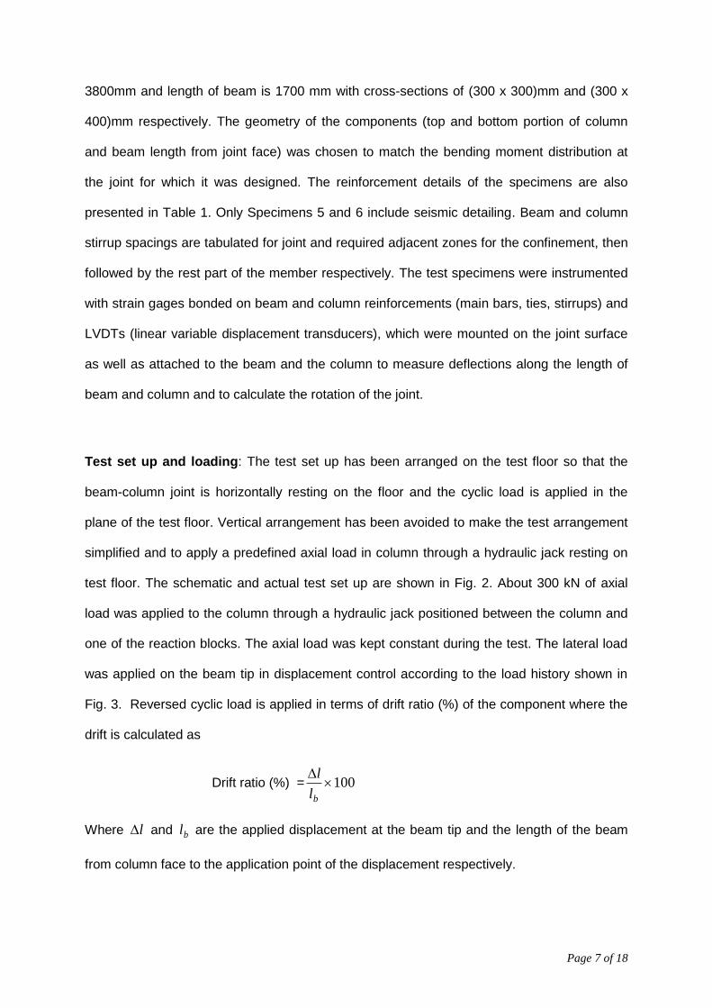
3800mm and length of beam is 1700 mm with cross-sections of (300 x 300)mm and (300 x
400)mm respectively. The geometry of the components (top and bottom portion of column
and beam length from joint face) was chosen to match the bending moment distribution at
the joint for which it was designed. The reinforcement details of the specimens are also
presented in Table 1. Only Specimens 5 and 6 include seismic detailing. Beam and column
stirrup spacings are tabulated for joint and required adjacent zones for the confinement, then
followed by the rest part of the member respectively. The test specimens were instrumented
with strain gages bonded on beam and column reinforcements (main bars, ties, stirrups) and
LVDTs (linear variable displacement transducers), which were mounted on the joint surface
as well as attached to the beam and the column to measure deflections along the length of
beam and column and to calculate the rotation of the joint.
Test set up and loading: The test set up has been arranged on the test floor so that the
beam-column joint is horizontally resting on the floor and the cyclic load is applied in the
plane of the test floor. Vertical arrangement has been avoided to make the test arrangement
simplified and to apply a predefined axial load in column through a hydraulic jack resting on
test floor. The schematic and actual test set up are shown in Fig. 2. About 300 kN of axial
load was applied to the column through a hydraulic jack positioned between the column and
one of the reaction blocks. The axial load was kept constant during the test. The lateral load
was applied on the beam tip in displacement control according to the load history shown in
Fig. 3. Reversed cyclic load is applied in terms of drift ratio (%) of the component where the
drift is calculated as
Drift ratio (%) = 100
bl
l
Where l and bl are the applied displacement at the beam tip and the length of the beam
from column face to the application point of the displacement respectively.

Page 8 of 18
The amplitudes of the peaks in the displacement history were multiples of the yield
displacement, whereas the yield displacement was defined as the tip displacement
corresponding to yielding of the beam top reinforcement at the column face. Three complete
cycles were performed at each displacement ductility level, if possible up to the maximum
travel of the actuator. The lateral displacement increments have been applied in a quasi-
static reverse cyclic manner. Although in the case of seismic action the loading rates are
higher than the rates corresponding to static conditions, it is advantageous since the quasi-
static cyclic testing allows a careful monitoring of the specimen behaviour during the test and
that strain-rate effects do not affect the material behaviour.
Results and discussion: During the test of the specimens, it was observed that the failure
of the GLD specimen (SP-1) is due to inadequacy of bond capacity of bottom main
reinforcement in beam as there is no such detailing against reverse loading (as shown in Fig.
4). When the structure is designed for earthquake loading but no such ductile detailing is
adopted (SP-3 and SP-4), the behaviour is much improved in comparison with SP-1, but
predominant shear failure of the joints and wedging out of concrete in joint has occurred (as
shown in Figs. 5-6). The failure pattern of both the specimens (based on Indian Standard and
Eurocode) is qualitatively the same. Cover cracking at the back of the column and loosening
of concrete integrity have been also noted under higher level of loading. Finally, the
specimens designed for earthquake load and detailed as per ductility requirement (SP-5 and
SP-6) showed a similar mode of failure as observed for SP-3 and SP-4, but with a spreading
of the wedge continuing in both top and bottom part of the column (shown in Figs. 7-8).
Though at initial stage of loading, bending cracks occurred in the beam and column outside
the joint, no such contribution in dissipating energy was noticed in further steps. Hence, the
major energy dissipation had taken place in the joint region only.

Page 9 of 18
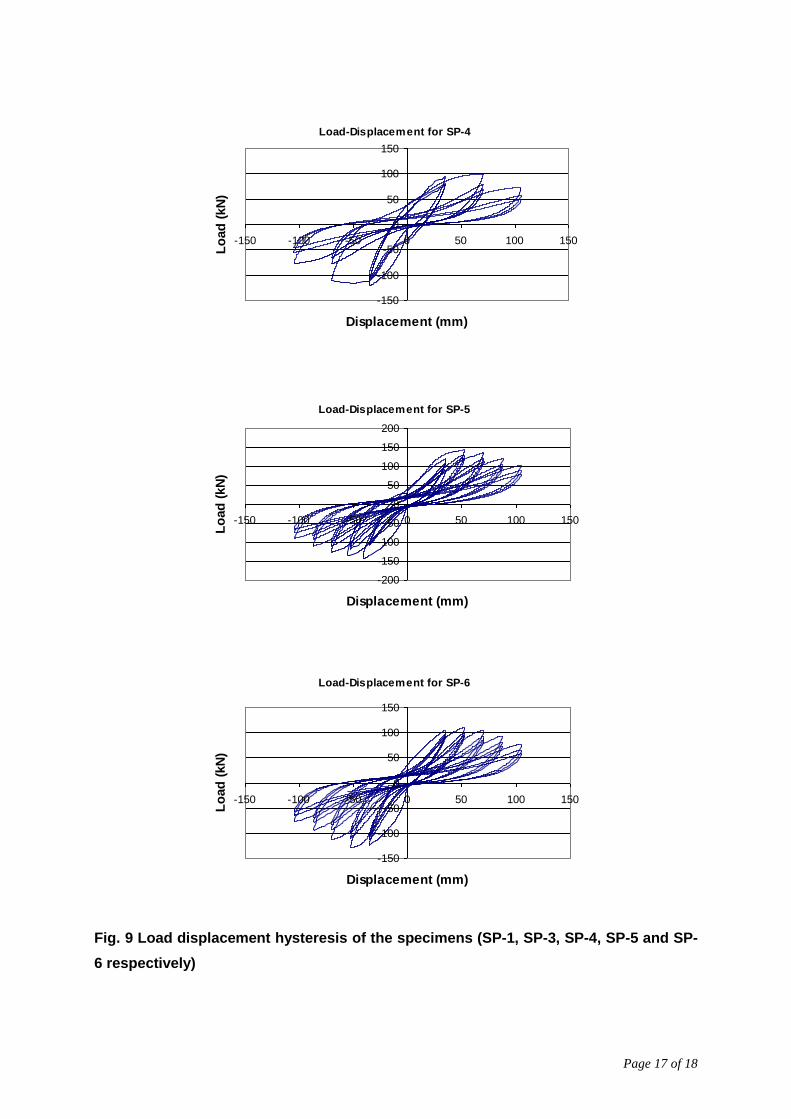
The most important parameter for seismic performance of structural D-regions can be
described by load-displacement hysteresis during the cyclic loading which can indicate the
ductility capacity and energy dissipation efficiency of the component. It is well proven that the
beam-column joint of reinforced concrete structures is the single crucial component in
dissipating seismic energy during earthquake. In view of this, load-displacement hysteresis
diagrams for each specimen (SP-1, SP-3, SP-4, SP-5 and SP-6) are presented in Fig. 9,
where these figures are drawn by obtaining the actuator data to get a fair qualitative
behaviour of the specimens. It shows the poor performance of the GLD structure and the
consequent improvement of the seismic performance as the design and detailing provisions
are upgraded. It is important to mention here that, though SP-3 and SP-4 show an improved
performance in comparison with SP-1, hysteresis behaviour has not been enhanced to the
desired extent due to its lacking in ductile detailing. This inadequacy is solved by the next
level of specimens, i.e. ductile detailed specimens (SP-5 and SP-6). Beside the qualitative
comparison, it is required to obtain the energy dissipation capacity of each of the joints which
would reflect the quantitative seismic performance. The cumulative energy dissipation
capacity with respect to the drift ratio of all the specimens considered in this study is
presented (as shown in Fig. 10) by considering the actual response from the LVDT placed
opposite to the actuator at the beam tip. The figure clearly depicts the improvement of the
specimens designed according to the upgradation of the standards. Among the seismically
analysed specimens without ductility detailing, though both the specimens (based on Indian
Standard and Eurocode) show a similar performance under low drift ratio, the specimen
designed according to Indian Standard (SP-3) exhibits better performance (with a 10% more
energy dissipation capacity) over the Eurocode (SP-4) with the increase in drift ratio. This is
due to higher percentage of reinforcement in both beam and column in specimen (SP-3). It is
further to note that the specimen (SP-6) has been designed according to Eurocode medium
ductile (DCM) design, hence performs not to that extent as that of the specimen designed
according to Indian Standard ductile design (25% less energy dissipation) which aims at full
ductility.

Page 10 of 18
Conclusion: In the present study, two widely used structural design guidelines (Eurocode
and Indian Standard) have been considered to evaluate the seismic performance of the
structural D-region with three different stages of codal evolution (GLD; seismic design
without ductile detailing; and seismic design with ductile detailing). The central objective of
the study is to evaluate the performance of the existing structures designed according to the
prevailing guidelines and further to identify the implications of the differences in the
guidelines on the seismic performance. It is observed that both the GLD and seismic design
without ductile detailed specimens possess a low energy dissipation capacity in comparison
with the ductile one. The specimens of second level (seismically designed but without ductile
detailing), though provide almost same deformability, the specimen designed according to
Indian Standard (SP-3) exhibits better performance over the Eurocode (SP-4) under higher
drift ratio, due to higher percentage of reinforcement in both beam and column in specimen
(SP-3). Further, among the third level specimens (ductile detailed specimen), the one based
on Indian Standard (SP-5) shows superior performance over the Eurocode design. It is due
to the fact that a medium ductility specification from Eurocode is adopted in this study and
further an option for high ductility still remains in Eurocode. On the other hand, there is no
such provision in Indian code to choose level of ductility than to provide the full ductile
detailing. The present study emphasises the fact that the existing reinforced concrete
structures which were GLD or non-ductile, require immediate and adequate upgradation to
avoid any catastrophic failure. Further, the structures with proper ductile detailing though
show a noticeable improvement in seismic performance, it differs from one code to another
and the detailing provisions of either code lead to put question on their practicability which
can be solved by further research on smart detailing or by using new materials. For
example, first test has been performed using fiber reinforced concrete in the joint region
which showed a significant improvement of the joint itself. The details of this test, however,
are not included in this paper.

Page 11 of 18
Acknowledgements: The authors are thankful to Dr. N.Lakshmanan, Director, SERC, for his suggestions, constant encourangement and providing excellent facility for conducting the tests at SERC, Chennai, India. The support received from the management, scientists and staff of SERC is also duly acknowledged.
References:
1. Beaufait, F. and Williams, R. R., “Experimental Study of Reinforced Concrete Frames Subjected to Alternating Sway Forces”, ACI J. Proc., V. 65, No. 11, 1968, pp. 980-984
2. Durrani, A. J. and Wight, J. K., “Behavior of Interior Beam-to-Column Connections Under Earthquake-Type Loading”, ACI J. Proc., V. 82, No. 3, 1985, pp. 343-349
3. Ehsani, M. R. and Wight, J. K., “Exterior Reinforced Concrete Beam-to-Column Connections Subjected to Earthquake-Type Loading”, ACI J. Proc., V. 82, No. 4, 1985, pp. 492-499
4. ACI-ASCE Committee 352, “Recommendations for Design of Beam-Column Joints in Monolithic Reinforced Concrete Structures”, American Concrete Institute, 1976
5. Ahmad, S. H. and Shah, S.P., “Behavior of Hoop Confined Concrete Under High Strain Rates”, ACI J. Proc., V. 82, No. 5, 1985, pp. 634-647
6. Aycardi, L.E., Mander, J. B. and Reinhorn, A. M. , “Seismic Resistance of Reinforced Concrete Frame Structures Designed Only for Gravity Loads: Experimental Performance of Subassemblages, ACI Structural J, V. 91, No. 5,1994, pp. 552-563
7. American Concrete Institute Committee ACI 318-89, “Building Code Requirements for Reinforced Concrete (ACI 318-89)”, American Concrete Institute, Detroit, 1989, 351 pp.
8. Bracci, J. M., Reinhorn, A. M. and Mander, J. B., “Seismic Resistance of Reinforced Concrete Frame Structures Designed for Gravity Loads: Performance of Structural System”, ACI Structural J., V. 92, No. 5, 1995, pp. 597-609
9. El-Attar, A. G., White, R. N. and Gergely, P., “Behaviour of Gravity Load Designed Reinforced Concrete Buildings Subjected to Earthquakes”, ACI Structural J., V. 94, No. 2, 1997, pp. 133-145
10. Hakuto, S., Park, R. and Tanaka, H., “Seismic Load Tests on Interior and Exterior Beam-Column Joints with Substandard Reinforcing Details”, ACI Structural J., V. 97, No. 1, 2000, pp. 11-25
11. NZS 3101, “The Design of Concrete Structures“,1995, Standards New Zealand, Wellington, 1995
12. Elwood, K. J. and Moehle, J. P., “Shake Table Tests on The Gravity Load Collapse of Reinforced Concrete Frames”, Seventh US National Conference on Earthquake Engineering, Boston, MA, Earthquake Engineering Research Institute, July 2002
13. Dhakal, R.P., Pan, T.-C., Irawan, P., Tsai, K.-C., Lin, K.-C. and Chen, C.-H., “Experimental Study on the Dynamic Response of Gravity-Designed Reinforced Concrete Connections”, Engineering Structures, V. 27, No. 1, 2005, pp. 75-87
14. BS 8110, “Structural Use of Concrete- Code of Practice for Design and Construction”, London: British Standards Institution; 1985

Page 12 of 18
15. American Concrete Institute Committee ACI318-02“Building Code Requirements for Reinforced Concrete (ACI 318-02)”, ACI 318-95, 99, 02, Detroit, Michigan, 1995, 1999, 2002
16. Han, S. W. and Jee, N.Y., “Seismic Behaviours of Columns in Ordinary and Intermediate Moment Resisting Concrete Frames”, Engineering Structures, V. 27, No. 6, 2005, pp. 951–962
17. Tsonos, A.G., “Cyclic Load Behavior of Reinforced Concrete Beam-Column Subassemblages of Modern Structures”, ACI Structural J., V. 104, No. 4, 2007, pp. 468-478
18. CEN Technical Committee 250, “Eurocode 2: Design of Concrete Structures-Part:1-1: General rules and rules for buildings” (EN 1992-1-1:2004), CEN, Berlin, Germany, 2005, 248 pp.
19. CEN Technical Committee 250/SC8, “Eurocode 8: Design of Structures for Earthquake Resistance-Part: 1: General Rules, Seismic Actions and Rules for Buildings (ENV 1998-1:2004),” CEN, Berlin, Germany, 2006, 192 pp.
20. Joint ACI-ASCE Committee 352, “Recommendations for Design of Beam-Column Connections in Monolithic Reinforced Concrete Structures (ACI 352R-02),” American Concrete Institute, Farmington Hills, Michigan, 2002, 37 pp.
21. ERC-1995, “New Greek Earthquake Resistant Code,” Athens, Greece, 1995, 145 pp. (in Greek)
22. Indian Standard (IS-456-2000), “Plain and Reinforced Concrete - Code of Practice”, Bureau of Indian Standards, New Delhi, 2000
23. Indian Standard (IS-13920-1993), “Ductile Detailing of Reinforced Concrete Structures Subjected to Seismic Forces — Code of Practice”, Bureau of Indian Standards, New Delhi, 2002

Page 13 of 18
Table 1: Specimens details
Specimens Code of practice Reinforcement details
Beam main Column main
Beam stirrup
Column stirrup
Specimen-1 (SP-1)
GLD IS 456-2000 (2+2
*)-16 top
(2+1*)-16 bot
(* =extra reinf)
4-25 2L
-8 @130 c/c
2L
-8@300 c/c
Specimen-3 (SP-3)
GLD+Seismic Load IS 456-2000 4-25 top
4-16+1-25 bot
12-25 2L
-8 @110 c/c
2L
-8@140 c/c
Specimen-4 (SP-4)
GLD+Seismic Load EC 2: 1-1:2004, EN 1990:2002 EC 8 (EN 1998-1:2004)
3-16+2-25 top
5-16 bot
8-25 2L
-8 @120 c/c
2L
-8@130 c/c
Specimen-5 (SP-5)
GLD+Seismic Load+ductile detailing
IS 456-2000, IS 13920-1998
4-25 top
4-16+1-25 bot
12-25 2L
-10 @100 /120 c/c
2L
-10@75/150 c/c
Specimen-6 (SP-6)
GLD+Seismic Load+ductile detailing (medium)
EC 2: 1-1:2004, EN 1990:2002 EC 8 (EN 1998-1:2004)
5-20 top
3-20 bot
8-25 2L
-10 @100/150 c/c
2L
-
10@120/200 c/c

Page 14 of 18
Figures:
Fig.1 General arrangement of the building frame considered for the study
(a)
(b)
Fig. 2 (a) Schematic diagram of the test set up placed on test floor, (b) actual set up [at
SERC, Chennai]
6m 6m 6m
3.5m
3.5m
3.5m Sub-assembly considered

Page 15 of 18
-10-9-8-7-6-5-4-3-2-10123456789
10
Time% D
rift
Fig.3 Typical cyclic load history adopted in experiments
Fig. 4 Failure pattern of Specimen 1 (SP-1) Fig. 5 Failure pattern of Specimen 3 (SP-3)
Fig. 6 Failure pattern of Specimen 4 (SP-4) Fig. 7 Failure pattern of Specimen 5 (SP-5)

Page 16 of 18
Fig. 8 Failure pattern of Specimen 6 (SP-6)
Load-Displacement for SP-1
-100
-80
-60
-40
-20
0
20
40
60
-60 -40 -20 0 20 40 60
Displacement (mm)
Lo
ad
(kN
)
Load-Displacement for SP-3
-150
-100
-50
0
50
100
150
-150 -100 -50 0 50 100 150
Displacement (mm)
Lo
ad
(kN
)
Page 17 of 18
Load-Displacement for SP-4
-150
-100
-50
0
50
100
150
-150 -100 -50 0 50 100 150
Displacement (mm)
Lo
ad
(kN
)
Load-Displacement for SP-5
-200
-150
-100
-50
0
50
100
150
200
-150 -100 -50 0 50 100 150
Displacement (mm)
Lo
ad
(kN
)
Load-Displacement for SP-6
-150
-100
-50
0
50
100
150
-150 -100 -50 0 50 100 150
Displacement (mm)
Lo
ad
(kN
)
Fig. 9 Load displacement hysteresis of the specimens (SP-1, SP-3, SP-4, SP-5 and SP-
6 respectively)

Page 18 of 18
0
10
20
30
40
50
60
70
80
0 1 2 3 4 5 6 7 8
Input drift ratio (%)
Cu
mu
lati
ve e
nerg
y d
issip
ati
on
(kN
m)
SP-1 SP-3 SP-4 SP-5 SP-6
Fig. 10 Cumulative energy dissipation capabilities of the specimens