Seismic Performance of Combined Grid System on Tall ...
15
International Journal of Research in Engineering and Science (IJRES) ISSN (Online): 2320-9364, ISSN (Print): 2320-9356 www.ijres.org Volume 9 Issue 7 ǁ 2021 ǁ PP. 14-28 www.ijres.org 14 | Page Seismic Performance of Combined Grid System on Tall Structures with Irregularity Condition Nimisha K J, Bincy V *1 Department of Civil Engineering, SNGCE, Kerala 2 Department of Civil Engineering, SNGCE, Kerala Corresponding Author: Nimisha K J Abstract Advancement in materials, construction technology accelerated the development of tall structures. Multi-storied structures need proper evaluation of loads for safe and economical design. The widely used internal lateral load resisting structural systems include rigid frame, braced frame, shear wall and outrigger structure whereas the exterior systems constitute tubular, diagrid, pentagrid, hexagrid and octagrid structures. The employment of grid structural systems in a building give rise to numerous advantages like reduction of interior columns giving large column free spaces that can be used as indoor sports auditoriums, exhibition halls etc. The inclined columns take up gravity as well as lateral loads unlike the conventional vertical columns. There are various studies regarding the seismic performance of grid system on tall structures with regular condition. The objective of this paper is to study the seismic performance of combined grid system on tall structures with irregular condition. Stiffness irregularity and geometric irregularity is introduced to the regular building and its performance is studied. A comparison of parameters Storey Shear, Storey drift, Storey displacement, Time period and Structural weight is done to determine the efficient and cost effective structure. ETABS V15 software is used for modelling and analysis of structural members. Keywords: Diagrid, Hexagrid, stiffness irregularity, Geometric irregularity, Seismic performance --------------------------------------------------------------------------------------------------------------------------------------- Date of Submission: 29-06-2021 Date of acceptance: 13-07-2021 --------------------------------------------------------------------------------------------------------------------------------------- I. INTRODUCTION Advancement in materials, construction technology accelerated the development of tall structures. Loading on tall buildings is different from that of low-rise buildings in many ways such as large accumulation of gravity loads on the bottom floor is more than top floors. Thus, multi-storied structures need proper evaluation of loads for safe and economical design. Except dead loads, the evaluation of loads cannot be done accurately. Live loads can be predicted approximately from a combination of experience and the previous field observations. Wind loads and earthquake loads are random in nature and it is difficult to predict them. They are evaluated based on a probabilistic approach. The widely used internal lateral load resisting structural systems include rigid frame, braced frame, shear wall and outrigger structure whereas the exterior systems constitute tubular, diagrid, pentagrid, hexagrid and octagrid structures. Lately, diagrid structural systems are adopted in tall buildings, owing to its structural efficiency and aesthetic potential.
Transcript of Seismic Performance of Combined Grid System on Tall ...

International Journal of Research in Engineering and Science (IJRES)
ISSN (Online): 2320-9364, ISSN (Print): 2320-9356 www.ijres.org Volume 9 Issue 7 ǁ 2021 ǁ PP. 14-28
www.ijres.org 14 | Page
Seismic Performance of Combined Grid System on Tall
Structures with Irregularity Condition
Nimisha K J, Bincy V *1Department of Civil Engineering, SNGCE, Kerala 2Department of Civil Engineering, SNGCE, Kerala
Corresponding Author: Nimisha K J
Abstract Advancement in materials, construction technology accelerated the development of tall structures. Multi-storied
structures need proper evaluation of loads for safe and economical design. The widely used internal lateral
load resisting structural systems include rigid frame, braced frame, shear wall and outrigger structure whereas
the exterior systems constitute tubular, diagrid, pentagrid, hexagrid and octagrid structures. The employment of
grid structural systems in a building give rise to numerous advantages like reduction of interior columns giving
large column free spaces that can be used as indoor sports auditoriums, exhibition halls etc. The inclined
columns take up gravity as well as lateral loads unlike the conventional vertical columns. There are various studies regarding the seismic performance of grid system on tall structures with regular condition. The
objective of this paper is to study the seismic performance of combined grid system on tall structures with
irregular condition. Stiffness irregularity and geometric irregularity is introduced to the regular building and
its performance is studied. A comparison of parameters Storey Shear, Storey drift, Storey displacement, Time
period and Structural weight is done to determine the efficient and cost effective structure. ETABS V15
software is used for modelling and analysis of structural members.
Keywords: Diagrid, Hexagrid, stiffness irregularity, Geometric irregularity, Seismic performance
---------------------------------------------------------------------------------------------------------------------------------------
Date of Submission: 29-06-2021 Date of acceptance: 13-07-2021 ---------------------------------------------------------------------------------------------------------------------------------------
I. INTRODUCTION
Advancement in materials, construction technology accelerated the development of tall structures.
Loading on tall buildings is different from that of low-rise buildings in many ways such as large accumulation
of gravity loads on the bottom floor is more than top floors. Thus, multi-storied structures need proper
evaluation of loads for safe and economical design. Except dead loads, the evaluation of loads cannot be done
accurately. Live loads can be predicted approximately from a combination of experience and the previous field
observations. Wind loads and earthquake loads are random in nature and it is difficult to predict them. They are
evaluated based on a probabilistic approach.
The widely used internal lateral load resisting structural systems include rigid frame, braced frame, shear wall and outrigger structure whereas the exterior systems constitute tubular, diagrid, pentagrid, hexagrid
and octagrid structures. Lately, diagrid structural systems are adopted in tall buildings, owing to its structural
efficiency and aesthetic potential.

Seismic Performance Of Combined Grid System On Tall Structures With Irregularity Condition
www.ijres.org 15 | Page
Figure1: Examples for diagrid structure
Some examples for diagrid structural system is shown in Fig 1. It is widely used for recent tall
buildings due to the structural efficiency and aesthetic potential. Hexagrid structural system can be used to
challenge the limit to building height in diagrid. The employment of Diagrid and Hexagrid systems in a building
lead to reduction of interior columns giving large column free spaces that can be used as indoor sports
auditoriums, exhibition halls etc. The inclined columns take up gravity as well as lateral loads unlike the
conventional vertical columns. Also, these systems lead to huge savings in terms of material cost.
The hexagrid structure consists of multiple hexagonal grids at the exterior perimeter surfaces of
building. The hexagrid system is a particular form of belt trusses mixed tubular system and resists lateral loads
acting in tension or compression. Module density of a hexagrid denotes the number of hexagon around the
periphery. If more number of modules can be incorporated around the periphery, the building is said to be of
high module density and vice-versa. In this paper, a combined grid structure with irregularity condition is modeled and compared with
regular structure. Combined grid structure is made by combining hexagrid and diagrid structural members. A
regular floor plan of 36 m × 36 m size is considered. ETABS software is used for modeling and analysis of
structural members. All structural members are designed as per IS 800:2007 considering all load combinations.
II. ANALYSIS AND DESIGN OF COMBINED GRID SYSTEM FOR REGULAR BUILDINGS
2.1 Building configuration
The 36 storey tall building is having 36 m × 36 m plan dimension. The storey height is 3.6 m. The
structural elements like columns, beams and diagrids are assigned structural steel properties while the slabs are
considered of RCC. For the design of diagrids and columns, built-up box sections are used and for the design of
beams, Indian Standard I-Sections are used. The typical plan and elevation are shown in Fig 2. In diagrid structures, pair of braces is located on the periphery of the building. The inclined columns are provided at six
meter spacing along the perimeter. The interior frame of diagrid structures is designed only for gravity load.
The design dead load and live loads on floor slab are 3.75 kN/m2 and 2.5 kN/m2 respectively. The dynamic
along wind loading is computed based on the basic wind speed of 30 m/sec and terrain category III as per
IS:875 (III)-1987. The design earthquake load is computed based on the zone factor of 0.16, medium soil,
importance factor of 1 and response reduction factor of 5 . Modeling, analysis and design of diagrid structure
are carried out using ETABS software. For linear static and dynamic analysis the beams and columns is
modeled by beam elements and braces are modeled by truss elements. The support conditions are assumed as
hinged. All structural members are designed using IS 800:2000. Secondary effect like temperature variation is
not considered in the design, assuming small variation in inside and outside temperature.
Beam sections are taken as same for all the storey. Each storey contains three types of beams-
B1(ISMB 550) ,B2(ISWB 600) and B 3( ISB 550). B3 is provided for exterior beams and B1 and B2 for interior beams. For these three structural systems, there are no vertical columns in the exterior of the structure
and also, only internal columns are there. The size of the interior vertical column is taken as 1500 x 1500 mm

Seismic Performance Of Combined Grid System On Tall Structures With Irregularity Condition
www.ijres.org 16 | Page
throughout the structure. 450 mm Pipe sections with 25 mm thickness column section is used from 1st to 18th
floor. 375 mm Pipe sections with12 mm thickness is used in 18th to 36th floor.
Figure 2 : Typical floor plan
2.2 Modeling Modeling, analysis and design of the structure are carried out using ETABS software. For linear static
and dynamic analysis the beams and columns is modeled by beam elements and braces are modeled by truss
elements. The support conditions are assumed as hinged. All structural members are designed using IS
800:2007. The elevation of diagrid and hexagrid structures are shown in figure 5. Diagrid is formed by
intersecting the diagonal and horizontal components and the hexagrid structure consists of multiple hexagonal
grids at the exterior perimeter surfaces of building.
Figure 3: Elevation view of hexagrid and diagrid structure
The combined grid structure is made by combining the hexagrid and diagrid members. In this paper the
diagrid and hexagrid structures are combined in three different ways, and hence three models are made. The
three models are analysed and compared to obtain the most effective model. Figure 4 shows the elevation of
three models made by combining diagrid and hexagrid.
Seismic Performance Of Combined Grid System On Tall Structures With Irregularity Condition
www.ijres.org 17 | Page
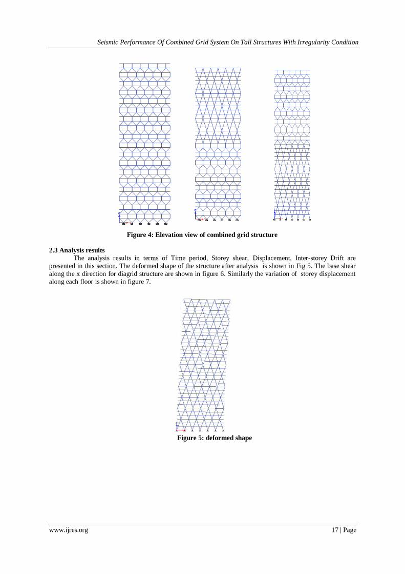
Figure 4: Elevation view of combined grid structure
2.3 Analysis results
The analysis results in terms of Time period, Storey shear, Displacement, Inter-storey Drift are
presented in this section. The deformed shape of the structure after analysis is shown in Fig 5. The base shear
along the x direction for diagrid structure are shown in figure 6. Similarly the variation of storey displacement
along each floor is shown in figure 7.
Figure 5: deformed shape

Seismic Performance Of Combined Grid System On Tall Structures With Irregularity Condition
www.ijres.org 18 | Page
Figure 6 : Story shear in x direction
Fig 7: Story displacement in x direction

Seismic Performance Of Combined Grid System On Tall Structures With Irregularity Condition
www.ijres.org 19 | Page
Fig 8: performance of Story displacement with story height for each model
Fig 9: performance of Story drift with story height for each model
After analysing and designing all the structures, the comparison of different parameters for all the models are
tabulated in the Table 1.
Table 1: comparison of models Model Time period (s) Storey
displacement(mm)
Storey drift (mm) Base shear(kN) Weight
(kN)
x y x y x y x y
Diagrid 3.04 3.1 357.1 362.41 .05654 .005666 34915 35767 443729
Hexagrid 3.168 3.187 354.738 354.099 .0662 0.006511 31883 31556 442464
One side dia
and hexa 2.95 3.24 361.95 347.81 0.00583 0.00603 13199 33235 443310
B- diagrid 2.87 2.88 352.82 351.51 0.0063 0.0062 22095 22458 443705
B- hexagrid 3.31 3.34 354.65 354.14 0.005855 0.00582 32984 34190 442693
0
5
10
15
20
25
30
35
40
0 100 200 300 400
Sto
ry n
o
Displacement
Story displacement -THx
daigrid
hexagrid
one side diagrid and hexagrid
1 to 18 hexagrid
1 to 18 diagrid
0
5
10
15
20
25
30
35
40
0 0.002 0.004 0.006 0.008
Sto
ry n
o.
Drift
Story drift- THx
daigrid
hexagrid
one side diagrid and hexagrid
1 to 18 hexagrid
1 to 18 diagrid

Seismic Performance Of Combined Grid System On Tall Structures With Irregularity Condition
www.ijres.org 20 | Page
2.4 Comparison of analysis results
a) Time period
Time period is a property of system, when it allows to vibrate freely without any external force and it
depends on mass and stiffness of the structure. Fundamental time period is inversely proportional to the
frequency of the structure. Figure 10 represents the comparison of the time period for the five models. It is
observed from the figure that for individual diagrid and hexagrid structure, time period is more. For
combined structure with diagrid at bottom, structure becomes stiffer & it has less time-period. But in
combined structure having hexagrid at bottom, time period is higher than that of individual structure. Thus
it is observed that the building with diagrid at bottom is stiffer among the five models.
Fig 10: Comparison of time period
b) Story drift
Story-Drift is the relative story displacement due to acting of total lateral load. It is defined as a Drift of one
level of multi-story relative to level belo. Story drift comparison for horizontal & vertical structural patterns is
plotted in the graphical form for different models as shown in figure 11.
Fig 11: Comparison of storey drift
2.6
2.7
2.8
2.9
3
3.1
3.2
3.3
3.4
Diagrid hexagrid
dia & hexa
B- dia B- hexa
X 3.04 3.168 2.953 2.871 3.314
Y 3.1 3.187 3.241 2.884 3.337
Tim
e
Time period comparison
0.0052
0.0054
0.0056
0.0058
0.0060
0.0062
0.0064
0.0066
Diagrid
hexagrid
dia & hexa
B- dia B- hexa
X 0.0057 0.0062 0.0058 0.0063 0.0059
Y 0.0057 0.0065 0.0060 0.0062 0.0058
Dri
frt
Storey drift(mm)

Seismic Performance Of Combined Grid System On Tall Structures With Irregularity Condition
www.ijres.org 21 | Page
c) Story displacement
Fig 12: Comparison of displacement
Figure 12 represent the comparison of the maximum top storey displacements for the systems. The
storey displacement of structure with diagrid at bottom has the least displacement of all the models and the
model. The individual diagrid structure is having the highest story displacement.
d) Base shear
Base shear is is the approximate maximum expected reactions that would be generated due to seismic ground
of motion at the base of the structure. Base shear for the five structural grids is plotted in the bar chart form as
shown in figure 13. When the building is symmetric, the base shear will be the same in both the directions. The
highest storey shear value is possessed by the structure with diagrid at bottom. The individual diagrid structure
has minimum storey shear value.
Fig 13: Comparison of base shear
340
345
350
355
360
365
Diagrid hexagrid
dia & hexa
B- dia B- hexa
X 357.1 354.738 361.945 352.817 354.645
Y 362.41 354.099 347.807 351.507 354.142
Dis
pla
cem
en
t
Storey displacement
0
5000
10000
15000
20000
25000
30000
35000
40000
Diagrid hexagrid
dia & hexa
B- dia B- hexa
X 34915 31883 13199 22095 32984
Y 35767 31556 33235 22458 34190
Shea
r
Base shear(kN)

Seismic Performance Of Combined Grid System On Tall Structures With Irregularity Condition
www.ijres.org 22 | Page
III. ANALYSIS AND DESIGN OF COMBINED GRID SYSTEM FOR IRREGULAR BUILDINGS
Irregular buildings constitute a large portion of the modern urban infrastructure. Structures are never
perfectly regular and hence the designers routinely need to evaluate the likely degree of irregularity and the
effect of this irregularity on a structure during an earthquake. When such buildings are located in a high seismic
zone, it becomes more than a concern. Uncertainties involved and behaviour studies are vital for all civil
engineering structures. In this section, response of combined grid structure subjected to lateral loads is studied
for stiffness and geometric irregularities.
3.1 Analysis of irregular structure- stiffness irregularity
Mass eccentricity of 5%, 10%, 15%, 20% and 25% is introduced to the regular building with combined
grid structure. Torsional performance is checked by finding Max.displacement(∆max) and Avrg. displacement(∆av).
After analysing and designing all the structures, the comparison of different parameters for all the
models are tabulated in the Table 2.
Table 2: Comparison of model for stiffness irregularity Model Time period (s) Storey
displacement(mm)
Storey drift (mm) Base shear(kN) Weight
(kN)
x y x y x y x y
Diagrid 2.87 2.88 352.82 351.51 0.0063 0.0062 22095 22458 443705
5% e 2.88 2.90 372.08 371.86 0.00698 0.006939 21585 21936 443705
10% e 2.88 2.94 379.63 378.96 0.00742 0.0074 20686 20844 443705
15%e 2.88 3.02 381.19 378.73 0.00741 0.0073 18638 18899 443705
20%e 2.88 3.12 362.55 362.37 0.00673 0.0067 16239 16676 443705
25% e 2.88 3.24 338.21 339.09 0.00607 0.00607 15791 15776 443705
Fig 14: performance of Story displacement with story height for stiffness irregularity
0
5
10
15
20
25
30
35
40
0 100 200 300 400 500
Sto
rey
No
.
Displacement (mm)
story displacement- THx
5%
10&
20%
25%
15%

Seismic Performance Of Combined Grid System On Tall Structures With Irregularity Condition
www.ijres.org 23 | Page
Fig 15: performance of Story displacement with story height for stiffness irregularity
Comparison of analysis results
a) Time period
Figure 16 represents the comparison of the time period for the models with varying eccentricity values. It is
observed from the figure that as eccentricity increases time period also increases.
Fig 16: Comparison of time period
b) Story drift
Figure 17 represents the comparison of the story drift for the models with varying eccentricity values. It is
observed from the figure that as eccentricity increases story drift value dcreases..
0
5
10
15
20
25
30
35
40
0 0.002 0.004 0.006 0.008
Sto
rey
no
.
drift
Story drift
5%
10&
15%
20%
25%
2.60
2.70
2.80
2.90
3.00
3.10
3.20
3.30
Diagrid
5% e 10% e 15% e 20% e 25% e
x 3.04 2.88 2.88 2.88 2.88 2.88
y 3.10 2.90 2.94 3.02 3.12 3.24
Tim
e p
erio
d
Comparison of time period

Seismic Performance Of Combined Grid System On Tall Structures With Irregularity Condition
www.ijres.org 24 | Page
Fig 17: Comparison of storey drift
c) Story displacement
Fig 18: Comparison of displacement
Figure 18 represents the comparison of the story displacement for the models with varying eccentricity values.
It is observed from the figure that as eccentricity increases story displacement value decreases.
d) Base shear
Figure 17 represents the comparison of the base shear for the models with varying eccentricity values. It is
observed from the figure that as eccentricity increases shear value decreases.
0
0.001
0.002
0.003
0.004
0.005
0.006
0.007
0.008
Diagrid
5% e 10% e 15% e 20% e 25% e
x 0.00565 0.00698 0.00742 0.00741 0.00673 0.00607
y 0.00567 0.00694 0.0074 0.0073 0.0067 0.00607
Sto
rey
dif
t
Comparison of storey drift
310.00
320.00
330.00
340.00
350.00
360.00
370.00
380.00
390.00
Diagrid
5% e 10% e 15% e 20% e 25% e
x 357.10 372.08 379.63 381.19 362.55 338.21
y 362.41 371.86 378.96 378.73 362.37 339.09
Sto
ry d
isp
lace
men
t
comparison of story displacement

Seismic Performance Of Combined Grid System On Tall Structures With Irregularity Condition
www.ijres.org 25 | Page
Fig 19: Comparison of base shear
3.2 Analysis and design of irregular structure- geometric irregularity In this section, combined grid structure is analysed for different plan shapes. For this purpose, three models are
created with different plan shapes- L shaped, T shaped and I shaped
Fig 20: different plan shapes
After analysing and designing all the structures, the comparison of different parameters for all the models are
tabulated in the Table 3
Table 3: comparison of buildings with different plan shapes Model Time period (s) Storey displacement(mm) Storey drift (mm) Base shear(kN) Weight
(kN)
x y x y x y x y
Regular 2.87 2.88 352.82 351.51 0.0063 0.0062 22095 22458 443705
L shape 2.68 3.08 371.14 323.79 0.0092 0.00623 16207 18864.36 350176
Tshape 2.84 2.85 348.05 347.47 0.0061 0.00614 18981 18816 349982
I shape 2.51 2.59 315.89 349.26 0.00488 0.0054 20293 22697 356703
Comparison of analysis results
a) Time period
Figure 14 represents the comparison of the time period for the geometric irregularity models. It is observed
from the figure that time period is more for the L shaped structure and it is less for I shaped structure.
0
5000
10000
15000
20000
25000
30000
35000
40000
Diagrid 5% e 10% e 15% e 20% e 25% e
x 34915 21585 20686 18638 16239 15791
y 35767 21936 20844 18899 16676 15776
Bas
e s
he
ar
Comparison of base shear

Seismic Performance Of Combined Grid System On Tall Structures With Irregularity Condition
www.ijres.org 26 | Page
Fig 21: Comparison of time period
b) Story drift
Story-Drift is the relative story displacement due to acting of total lateral load. It is defined as a Drift of one
level of multi-story relative to level below. Story drift comparison is plotted in the graphical form for different
models as shown in figure 22. Story drift value is minimum for the I shaped structure.
Fig 22: Comparison of storey drift
0.00
0.50
1.00
1.50
2.00
2.50
3.00
3.50
Diagrid L shape Tshape I shape
x 2.87 2.68 2.84 2.51
y 2.88 3.08 2.85 2.59
Tim
e p
eri
od
Comparison of time period
0 0.001 0.002 0.003 0.004 0.005 0.006 0.007 0.008 0.009
0.01
Diagrid L shape Tshape I shape
x 0.005654 0.0092 0.0061 0.00488
y 0.005666 0.00623 0.00614 0.0054
Sto
rey
dri
ft
Comparison of storey drift

Seismic Performance Of Combined Grid System On Tall Structures With Irregularity Condition
www.ijres.org 27 | Page
c) Story displacement
Fig 23: Comparison of displacement
Figure 23 represent the comparison of the maximum top storey displacements for the systems. The
storey displacement of the T shaped structure is less compared to regular structures..
d) Base shear
Base shear is is the approximate maximum expected reactions that would be generated due to seismic ground
of motion at the base of the structure. Base shear for the geometric irregular models are plotted in the bar chart
form as shown in figure 24. Compared to regular structure, base shear value is minimum for irregular structures.
Fig 24: Comparison of base shear
IV. CONCLUSION
In this paper, analysis and design of 36 storey diagrid steel building is presented in detail. A regular
floor plan of 36 m ×36 m size is considered. ETABS software is used for modeling and analysis of structure. All
structural members aredesigned using IS 800:2007 considering all load combinations. Load distribution in
diagrid system is also studied for 36 storey building.
280.00 290.00 300.00 310.00 320.00 330.00 340.00 350.00 360.00 370.00 380.00
Diagrid L shape Tshape I shape
x 352.82 371.14 348.05 315.89
y 351.51 323.79 347.47 349.26
Sto
rey
dis
pla
cem
en
t
Comparison of storey displacement
0
5000
10000
15000
20000
25000
30000
35000
40000
Diagrid L shape
Tshape I shape
x 34915 16207 18981 20293
y 35767 18864.4 18816 22697
Bas
e s
he
ar
Comparison of base shear

Seismic Performance Of Combined Grid System On Tall Structures With Irregularity Condition
www.ijres.org 28 | Page
Diagrid is having less time period and low drift value compared to hexagrid structure
Hexagrid is having low storey displacement and base shear than diagrid structure.
When compared to diagrid, hexagrid is more effective since it is having low storey displacement and base
shear and low weight.
Among the combined structures, structure with diagrid at bottom half and hexagrid at top is found to be
more effective. It has more stiffness. It is also having lower displacement and base shear values. Hence the
stability of structure is increased.
Stiffness irregularity is given to the building by giving mass eccentricity of 5%,10%,15%,20% and 25%
and torsion limit is checked.
Upto 25% the value of ∆max/∆av is within the limit 1.5 So upto an eccentricity of 25% the building is safe.
Compared to individual structure, I shaped building is having lower drift value and time period. For L shaped building, there is significant decrease in base shear value.
Base shear value is less for one side set back building compared to two side set back building
REFERENCES [1]. Harish Varsani, Narendra Pokar and Dipesh Gandhi, “Comparative study of diagrid structural system and conventional structural
system for high rise steel building,” IJAREST, Vol. 2, Issue 1, January 2015.
[2]. Giulia Milana, Pierluigi Olmati, Konstantinos Gkoumas, Franco Bontempi, “Ultimate capacity of diagrid systems for tall buildings
in nominal configuration and damage state,” Periodica Polytechnia Civil Engineering, pp:381-391, Feb-2015.
[3]. Nilang Jaswani, Prof. Dhruti Dhyani, “Parametric study on diagrid structure system for high rise building” IJAREST, Vol. 02, Issue
05, May 2015.
[4]. Raghunath D. Deshpande, Sadanand M. Patil, Subramanya Ratan, “Analysis and comparison of diagrid and conventional structural
system,” IJRET, Vol. 02, Issue 03, June-2015.
[5]. Saket Yadav, and Dr. Vivek Garg, “Advantages of steel diagrid building over Conventional building,” IJCSER, Vol. 3, Issue 1,
pp:394-406, April 2015-September 2015.
[6]. Shahana E. and Aswathy S. Kumar, “Comparative study of diagrid structure with and without corner columns,” IJSR, Vol. 5, Issue
7, July 2016
[7]. Anju Krishna, Arathi S, “Analytical study of vertical geometric irregular diagrid structure and comparison with tubular structure,”
IJSR, Vol. 05, Issue 07, July-2016.
[8]. Manthan Shah, Snehal V. Mevada, Vishal B. Patel, “Comparative study of diagrid structures with conventional frame structures,”
in ISSN:2248-9622, Vol. 6, Issue 5, (part-2) May 2016, pp. 22-29.
[9]. Dr. Gopisiddappa, Divyashree M. and Sindhuja G. J., “performance study of high rise building with diagrid system under dynamic
loading,” IRJET, Volume: 04, Issue: 06, June-17.
[10]. Mingze Sun, “A Comparative Study on the Seismic Performance of Concrete and Steel Diagrid Structures” Massachusetts Institute
of Technology, June 2015.
[11]. Femy Mariya Thomas, Binu M. Issac and Jessymol George,” performance evaluation of tall buildings with steel diagrid system”
2nd International Conference on science, Technology and management, September 2015.
[12]. Ravish Khan and S. B. Shinde, “Analysis of diagrid structure in comparison with exterior braced frame structure,” IJRET, Vol. 04,
Issue 12, December 2015.
[13]. Amol V. Gorle, S. D. Gowardhan, “Optimum performance of diagrid structure,” IJER, Volume No. 05, Issue: Special 03, 2016.