NEW DESIGN CONSIDERATIONS FOR SEISMIC ISOLATED BUILDINGS ...

1
Seismic joint system specially designed for base isolated buildings
Tech
nica
l bro
chur
e
SYSTEM

CLOSING LIMIT MOVEMENT
OPENING LIMIT MOVEMENT
LONGITUDINAL MOVEMENTTRANSVERSE MOVEMENT
Ramp for the sliding of the system, exceeded the maximum movement.
Allowed by the dimensioning of the bridge, as to maintain always the coverage of the joint.
Allowed by the patented sliding trolleys system.
Managed by modules made of reinforced rubber, +/- 100mm of movement each one.
Module 1
Module 2
Seismic joint system specially designedfor base isolated buildings
2

3
STRENGTH
The hight-performance central element consists of aluminum I-Beams.
Watch the 3D simulation
K 3DSeismic joint system for joints up to 1000 mm subject to high movements up to +/ – 950 mm, specially designed for base isolated buildings. Suitable for loads by cars. The system consists of a rectangular section devoid of underfloor brackets and visible screws. Central plate rigid and antislip, made of knurled aluminium. Gaskets made of rubber with high resistance to vertical loads.
The system supports the movement in 3 directions, a special system of sliding on rollers allows longitudinal movements.
Base isolation is a technique developed to minimise damage to buildings during an earthquake, isolating the structure from potentially dangerous ground motions.
To ensure this advantage is also essential to separate the building from structures adjacent to the entire perimeter by joints larger than the movements expected during the earthquake.
SEISMIC JOINT COVERS have a key role to play:
• To ensure the movement in the two directions of the plane equal to the movement of the isolators.
• To avoid seismic pounding between adjacent building structures.
• To cover the expansion joints during movements in order to ensure a safe transit to people along the escape routes.
• To don’t allow the collapse of the system or other objects from the joint during the movements.
• To provides a flat surface for a bumpless transit of people, wheelchairs, stretchers and machinery, even during seismic movements.
• Durability, thanks to the use of materials not subject to corrosion or deterioration.
Failure to comply with these requirements may jeopardize the proper functioning of base isolation and make it impossible to use escape routes during and after a seismic event.
3
Base traditional Base isolation
Seismic joint system specially designed for base isolated buildings

4
DLS = ULS SIMULATION
Standard position
Sliding
Sliding
Vertical movement
Vertical movement
Maximum opening
Maximum opening

5
To mitigate the seismic risk is also:• To safeguard the integrity of the various components of a building structure, through an
appropriate joint dimensioning to avoid seismic pounding.• To protect the integrity and / or functionality of non-structural components, among which the expansion joints in the floor, whose malfunction or collapse in case of earthquake can cause also serious effects, invalidating for example the availability of some passages (escape routes) or even leaving in the floors, the openings in which people , stretchers or wheelchairs can find obstacle to escape. An estimate of the width of the joint to be considered “significant” may be made, for example, noting that safety legislation considers a dangerous gap with width over 20 cm, and therefore to be protected.About the above, recent legislation it has provided some indication rather accurate. Referring in particular to the DM 14.1.2008 and 6.5.2008, the very definition of the limit state DLS (Damage Limit State) and OLS (Operational Limit State) refers to the behavior of “non-structural parts.”. It requires, for example, that at the DLS the building as a whole, including the non-structural elements, “must not be damaged and must be operational” or “be damaged such as not to endanger the users” remaining immediately usable, despite the interruption of the usability of part of the devices
extracts of standards “=(NTC 2008: 7.2.3): “With the exception of interior infill walls [...], the non-structural elements, which if disrupted, can cause damage to people [...] must be verified for the seismic action corresponding to each limit state considered”
The expansion joint systems must be able to allow the movements OLS, without suffering no damage during the earthquake, during the movements DLS there must be no falls of components during earthquake and, out of this; the passage should be still accessible.the jointing systems are therefore an integral part of life and the level of security of any major structure, obviously with particular reference to seismically isolated and in the public and strategic buildings, such as hospitals, schools, shopping centers and large production buildings.The design of systems TECNO K JOINTS, entirely Italian, takes full account of these legislative parameters, respectively accounting for the fulfillment of the DLS and ULS (ultimate Limit State) through specific “thermal motion”, “seismic movement” and “last movement.” The K-Series 3D finally, provides the fulfillment of the most stringent specifications, typical for example of the isolated structures, also thanks to the possibility of compensating movements in both directions of the plane.
The joint systems must meet specific performance specifications of design and usability movement, directly related to the different limit states project: there is less and less room for improvisation
5
MOVEMENTS
6
Stiffening dynamic system with alignments bars
6
MOVEMENTSDETAIL
patended slidingtrolleys system with cylindrical bearings
Seismic joint system specially designedfor base isolated buildings
7
MOVEMENTSDETAIL
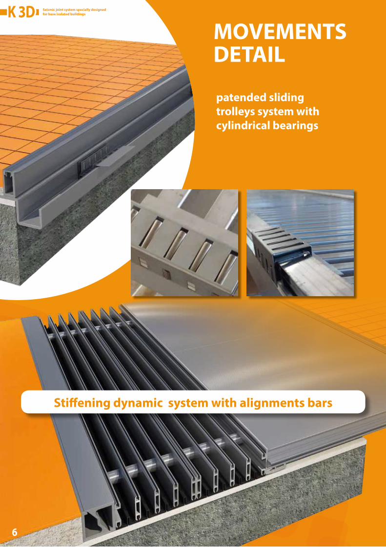
The system (as represented in the drawing) thanks to the positioning of the central bridge, cantilevered into the joint, manages all the longitudinal movements by scrolling to the left of the columns and the adjacent walls, thus making indefinite the movement capability relative. The elastic resistance of the rubber seals do not affect the structural calculation of the structures connected with the system K3D. The gaskets exceeded the movement competent, it is disengaged allowing the vehicle to slide transversely to the joint
Standard position Longitudinal movement - 800mm Longitudinal movement - 800mmTransverse movement - 800mm Transverse movement - 800mm
The system remain flush with finished floor, not creating obstacles to usability of escape routes during the earthquake to stretchers, wheelchairs and pedestrians.
FLAT SURFACE
SEISMIC POUNDING

Seismic joint system specially designedfor base isolated buildings
Tipo G L Mov. SLD
Mov.SLU
mm mm mm mm
K 3D G100 M50 100 325 +/- 50 +/- 50
K 3D G150 M100 150 495 +/- 100 +/- 100
K 3D G200 M100 200 545 +/- 100 +/- 100
K 3D G200 M150 200 675 +/- 150 +/- 150
K 3D G250 M100 250 595 +/- 100 +/- 100
K 3D G250 M100 U200 250 695 +/- 100 +/- 200
K 3D G250 M200 250 845 +/- 200 +/- 200
K 3D G300 M100 300 645 +/- 100 +/- 100
K 3D G300 M100 U250 300 795 +/- 100 +/- 250
K 3D G300 M250 300 1025 +/- 250 +/- 250
K 3D G350 M100 350 695 +/- 100 +/- 100
K 3D G350 M100 U300 350 895 +/- 100 +/- 300
K 3D G350 M200 U300 350 1045 +/- 200 +/- 300
K 3D G350 M300 350 1195 +/- 300 +/- 300
K 3D G400 M100 400 745 +/- 100 +/- 100
K 3D G400 M100 U350 400 995 +/- 100 +/- 350
K 3D G400 M200 U350 400 1145 +/- 200 +/- 350
K 3D G400 M300 400 1245 +/- 300 +/- 300
K 3D G400 M300 U350 400 1295 +/- 300 +/- 350
Tipo G L Mov. SLD
Mov.SLU
mm mm mm mm
K 3D G450 M100 450 +/- 100 +/- 100
K 3D G450 M100 U400 450 +/- 100 +/- 400
K 3D G450 M200 U400 450 +/- 200 +/- 400
K 3D G450 M300 450 +/- 300 +/- 300
K 3D G450 M300 U400 450 +/- 300 +/- 400
K 3D G500 M100 500 +/- 100 +/- 100
K 3D G500 M100 U450 500 +/- 100 +/- 450
K 3D G500 M200 U450 500 +/- 200 +/- 450
K 3D G500 M300 U450 500 +/- 300 +/- 450
K 3D G600 M200 600 +/- 200 +/- 200
K 3D G600 M200 U550 600 +/- 200 +/- 550
K 3D G600 M300 U550 600 +/- 300 +/- 550
K 3D G700 M300 700 +/- 300 +/- 300
K 3D G700 M300 U650 700 +/- 300 +/- 650
K 3D G800 M300 800 +/- 300 +/- 300
K 3D G800 M300 U750 800 +/- 300 +/- 750
K 3D G900 M300 900 +/- 300 +/- 300
K 3D G900 M300 U850 900 +/- 300 +/- 850
K 3D G1000 M300 1000 +/- 300 +/- 300
K 3D G1000 M300 U950 1000 +/- 300 +/- 950
The table shows only some examples, consult our technical department for intermediate cases.
Dimensions:
= Laying surface lower = 100
= Laying surface major = 70+ (M if absent U) + 150 (for each module M 100 mm) + 80 (for each module M 50 mm)B
B
B
U
A
A
A
= B + G + 25
Ltot = Overall dimensions = B + G + A
B A
8
795
1095
1245
1295
1395
845
1195
1345
1495
1195
1545
1695
1545
1895
1645
2095
1745
2295
1845
2495
Seismic joint system specially designedfor base isolated buildings

The movements to the DLS (Damage limitation state) are handled by the system gaskets, always guaranteeing a smooth transition surface without hindrance. Exceeded these movements the system is designed to continue to ensure, however, the coverage of the gap (preventing things and people from falling into the gap) and the Free movement of the structures, up to the ULS (ULTIMATE LIMIT STATE). As it can be seen from the drawings, in the closing phase the system goes up the inclined ramp to slide on the adjacent flooring. In the opening phase the system runs on the laying surface, of sufficient amplitude to guarantee the support a planar surface. SO it IS ALWAYS BETTER TO CHOOSE THE SYSTEM WITH DLS COINCIDING WITH ULS to guarantee the flatness of the escape routes.
disconnection of gasket modules exceeded the DLS
residual support when fully opened
disconnection of gasket modules exceeded the DLS
9
ULS > DLS SIMULATION

The seismic joint K3D can be equipped with fire system K FIRE PAD for joints width of up to 1.2 m. The system is fixed to the two sides of the structure and can be sized in such a way as to guarantee the expected movements. Returned to the standard position will again be able to guarantee resistance EI 120 or EI 180 as requested.
The K FIRE PAD, certified according to UNI EN 1366-4: 2010 with characteristics EI 120 or EI 180, also allows the protection of the seismic isolators guaranteeing the effectiveness even after the movements caused by the earthquake..
1525
120
34
18030
�xing support with
metal eyelets, for
threaded rod with
Nut and Washer
The system is made of a single piece long enough to cover the four sides of the pillar
Application example on isolators
K FIRE PAD 600- for joints between pillar and floor- joint nominal width 350 mm- total movement required 500 mm (+/- 250 mm)- EI 120
FIRE PROTECTION

1111

Seismic joint system specially designedfor base isolated buildings
12
Tecno K Giunti S.r.l.Sede legale:
Via Laurentina (km 25), n°68Pomezia 00040 (RM) ItalyC.F. e P.Iva: 12059091004
edition GEN 2016
General catalogue
Stabilimento produttivo,ufficio tecnico e commerciale:
Via Pietà, n°96 - Savignano sul Rubicone 47039 (FC) Italyt. +39 0541 945909 - f. +39 0541 [email protected]