Seismic Isolation and Energy Dissipation - The University of
38
FEMA 356 Seismic Rehabilitation Prestandard 9-1 9. Seismic Isolation and Energy Dissipation 9.1 Scope This chapter sets forth requirements for the Systematic Rehabilitation of buildings using seismic isolation and energy dissipation systems. Section 9.2 provides analysis and design criteria for seismic isolation systems. Section 9.3 provides analysis and design criteria for passive energy dissipation systems. Components and elements in buildings with seismic isolation and energy dissipation systems shall also comply with the requirements of Chapters 1 through 8 and 11 of this standard, unless modified by the requirements of this chapter. C9.1 Scope The basic form and formulation of requirements for seismic isolation and energy dissipation systems have been established and coordinated with the Rehabilitation Objectives, target Building Performance Levels, and seismic ground shaking hazard criteria of Chapter 1 and the linear and nonlinear procedures of Chapter 3. Criteria for modeling the stiffness, strength, and deformation capacities of conventional structural components of buildings with seismic isolation or energy dissipation systems are given in Chapters 5 through 8 and Chapter 10. Limited guidance for other special seismic systems, including active control systems, hybrid active and passive systems, and tuned mass and liquid dampers, is provided in this chapter. Special seismic protective systems should be evaluated as possible rehabilitation strategies based on the Rehabilitation Objectives established for the building. Seismic isolation and energy dissipation systems are viable design strategies that have already been used for seismic rehabilitation of a number of buildings. Other special seismic protective systems—including active control, hybrid combinations of active and passive energy devices, and tuned mass and liquid dampers— may also provide practical solutions in the near future. These systems are similar in that they enhance performance during an earthquake by modifying the building’s response characteristics. Seismic isolation and energy dissipation systems will not be appropriate design strategies for most buildings, particularly buildings that have only Limited Rehabilitation Objectives. In general, these systems will be most applicable to the rehabilitation of buildings whose owners desire superior earthquake performance and can afford the special costs associated with the design, fabrication, and installation of seismic isolators and/or energy dissipation devices. These costs are typically offset by the reduced need for stiffening and strengthening measures that would otherwise be required to meet Rehabilitation Objectives. Seismic isolation and energy dissipation systems are relatively new and sophisticated concepts that require more extensive design and detailed analysis than do most conventional rehabilitation schemes. Similarly, design (peer) review is required for all rehabilitation schemes that use either seismic isolation or energy dissipation systems. Seismic isolation and energy dissipation systems include a wide variety of concepts and devices. In most cases, these systems and devices will be implemented with some additional conventional strengthening of the structure; in all cases they will require evaluation of existing building elements. As such, this chapter supplements the requirements of other chapters of this document with additional criteria and methods of analysis that are appropriate for buildings rehabilitated with seismic isolators and/or energy dissipation devices.
Transcript of Seismic Isolation and Energy Dissipation - The University of

9. Seismic Isolation and Energy Dissipation
9.1 Scope This chapter sets forth requirements for the Systematic Rehabilitation of buildings using seismic isolation and energy dissipation systems. Section 9.2 provides analysis and design criteria for seismic isolation systems. Section 9.3 provides analysis and design criteria for passive energy dissipation systems.
Components and elements in buildings with seismic isolation and energy dissipation systems shall also comply with the requirements of Chapters 1 through 8 and 11 of this standard, unless modified by the requirements of this chapter.
C9.1 Scope The basic form and formulation of requirements for seismic isolation and energy dissipation systems have been established and coordinated with the Rehabilitation Objectives, target Building Performance Levels, and seismic ground shaking hazard criteria of Chapter 1 and the linear and nonlinear procedures of Chapter 3.
Criteria for modeling the stiffness, strength, and deformation capacities of conventional structural components of buildings with seismic isolation or energy dissipation systems are given in Chapters 5 through 8 and Chapter 10.
Limited guidance for other special seismic systems, including active control systems, hybrid active and passive systems, and tuned mass and liquid dampers, is provided in this chapter.
Special seismic protective systems should be evaluated as possible rehabilitation strategies based on the Rehabilitation Objectives established for the building.
Seismic isolation and energy dissipation systems are viable design strategies that have already been used for seismic rehabilitation of a number of buildings. Other special seismic protective systems—including active control, hybrid combinations of active and passive energy devices, and tuned mass and liquid dampers—may also provide practical solutions in the near future. These systems are similar in that they enhance performance during an earthquake by modifying the building’s response characteristics.
Seismic isolation and energy dissipation systems will not be appropriate design strategies for most buildings, particularly buildings that have only Limited Rehabilitation Objectives. In general, these systems will be most applicable to the rehabilitation of buildings whose owners desire superior earthquake performance and can afford the special costs associated with the design, fabrication, and installation of seismic isolators and/or energy dissipation devices. These costs are typically offset by the reduced need for stiffening and strengthening measures that would otherwise be required to meet Rehabilitation Objectives.
Seismic isolation and energy dissipation systems are relatively new and sophisticated concepts that require more extensive design and detailed analysis than do most conventional rehabilitation schemes. Similarly, design (peer) review is required for all rehabilitation schemes that use either seismic isolation or energy dissipation systems.
Seismic isolation and energy dissipation systems include a wide variety of concepts and devices. In most cases, these systems and devices will be implemented with some additional conventional strengthening of the structure; in all cases they will require evaluation of existing building elements. As such, this chapter supplements the requirements of other chapters of this document with additional criteria and methods of analysis that are appropriate for buildings rehabilitated with seismic isolators and/or energy dissipation devices.
FEMA 356 Seismic Rehabilitation Prestandard 9-1

Chapter 9: Seismic Isolation and
Energy Dissipation
Seismic isolation is increasingly being considered for historic buildings that are free-standing and have a basement or bottom space of no particular historic significance. In selecting such a solution, special consideration should be given to the possibility that historic or archaeological resources may be present at the site. If historic or archaeological resources are present at the site, the guidance of the State Historic Preservation Officer should be obtained in a timely manner. Isolation is also often considered for essential facilities, to protect valuable contents, and on buildings with a complete but insufficiently strong lateral-force-resisting system.
Conceptually, isolation reduces response of the superstructure by “decoupling” the building from the ground. Typical isolation systems reduce forces transmitted to the superstructure by lengthening the period of the building and adding some amount of damping. Added damping is an inherent property of most isolators, but may also be provided by supplemental energy dissipation devices installed across the isolation interface. Under favorable conditions, the isolation system reduces drift in the superstructure by a factor of at least two—and sometimes by as much as factor of five—from that which would occur if the building were not isolated. Accelerations are also reduced in the structure, although the amount of reduction depends on the force-deflection characteristics of the isolators and may not be as significant as the reduction of drift. Reduction of drift in the superstructure protects structural components and elements, as well as nonstructural components sensitive to drift-induced damage. Reduction of acceleration protects nonstructural components that are sensitive to acceleration-induced damage.
Passive energy dissipation devices add damping (and sometimes stiffness) to the building. A wide variety of passive energy dissipation devices are available, including fluid viscous dampers, viscoelastic materials, and hysteretic devices. Ideally, energy dissipation devices dampen earthquake excitation of the structure that would otherwise cause higher levels of response and damage to components of the building. Under favorable conditions, energy dissipation devices reduce drift of the structure by a factor of about two to three (if no stiffness is added) and by larger factors if the devices also add stiffness to the structure. Energy dissipation devices will also reduce force in the structure—provided the structure is responding elastically—but would not be expected to reduce force in structures that are responding beyond yield.
Active control systems sense and resist building motion, either by applying external force or by modifying structural properties of active elements (e.g., so-called “smart” braces). Tuned mass or liquid dampers modify properties and add damping to key building modes of vibration.
Special seismic systems, such as isolation or energy dissipation systems, should be considered early in the design process and be based on the Rehabilitation Objectives established for the building (Chapter 2). Whether a special seismic system is found to be the “correct” design strategy for building rehabilitation will depend primarily on the performance required at the specified level of earthquake demand. In general, special seismic systems will be found to be more attractive as a rehabilitation strategy for buildings that have more stringent Rehabilitation Objectives (i.e., higher levels of performance and more severe levels of earthquake demand). Table C9-1 provides some simple guidance on the performance levels for which isolation and energy dissipation systems should be considered as possible design strategies for building rehabilitation.
9-2 Seismic Rehabilitation Prestandard FEMA 356

Chapter 9: Seismic Isolation and
Energy Dissipation
9.2 Seismic Isolation Systems
9.2.1 General Requirements
Seismic isolation systems using seismic isolators, classified as either elastomeric or sliding, as defined in Section 9.2.2, shall comply with the requirements of Section 9.2. Properties of seismic isolation systems shall be based on Section 9.2.2. Seismic isolation systems shall be designed and analyzed in accordance with Section 9.2.3. Linear and nonlinear analyses shall be performed, as required by Section 9.2.3, in accordance with Sections 9.2.4 and 9.2.5, respectively. Nonstructural components shall be rehabilitated in accordance with Section 9.2.6. Additional requirements for seismic isolation systems as defined in Section 9.2.7 shall be met. Seismic isolation systems shall be reviewed and tested in accordance with Sections 9.2.8 and 9.2.9, respectively.
The seismic isolation system shall include wind-restraint and tie-down systems, if such systems are required by this standard. The isolation system also shall include supplemental energy dissipation devices, if such devices are used to transmit force between the structure above the isolation system and the structure below the isolation system.
For seismically isolated structures, the coefficients C0, C1, C2, C3, and J defined in Chapter 3, shall be taken as 1.0
Table C9-1 suggests that isolation systems should be considered for achieving the Immediate Occupancy Structural Performance Level and the Operational Nonstructural Performance Level. Conversely, isolation will likely not be an appropriate design strategy for achieving the Collapse Prevention Structural Performance Level. In general, isolation systems provide significant protection to the building structure, nonstructural components, and contents, but at a cost that precludes practical application when the budget and Rehabilitation Objectives are modest.
Energy dissipation systems should be considered in a somewhat broader context than isolation systems. For the taller buildings (where isolation systems may not be feasible), energy dissipation systems should be considered as a design strategy when performance goals include the Damage Control Performance Range. Conversely, certain energy dissipation devices are quite economical and might be practical for performance goals that address only Limited Safety. In general, however, energy dissipation systems are more likely to be an appropriate design strategy when the desired Structural Performance Level is Life Safety, or perhaps Immediate Occupancy. Other objectives may also influence the decision to use energy dissipation devices, since these devices can also be useful for control of building response due to small earthquakes, wind, or mechanical loads.
Table C9-1 Applicability of Isolation and Energy Dissipation Systems
PerformanceLevel
PerformanceRange Isolation
EnergyDissipation
Operational Damage Control
Very Likely
Limited
ImmediateOccupancy
Likely Likely
LifeSafety
Limited Safety
Limited Likely
CollapsePrevention
NotPractical
Limited
C9.2.1 General Requirements
Analysis methods and design criteria for seismic isolation systems are based on criteria for the Rehabilitation Objectives of Chapter 1.
The methods described in this section augment the analysis requirements of Chapter 3. The analysis methods and other criteria of this section are based largely on FEMA 302, 1997 NEHRP Provisions.
FEMA 356 Seismic Rehabilitation Prestandard 9-3

Chapter 9: Seismic Isolation and
Energy Dissipation
9.2.2 Mechanical Properties and Modeling of Seismic Isolation Systems
9.2.2.1 General
Seismic isolators shall be classified as either elastomeric or sliding. Elastomeric isolators shall include any one of the following: high-damping rubber bearings (HDR), low-damping rubber bearings (RB) or low-damping rubber bearings with a lead core (LRB). Sliding isolators shall include flat assemblies or have a curved surface, such as the friction-pendulum system (FPS). Rolling systems shall be characterized as a subset of sliding systems. Rolling isolators shall be flat assemblies or have a curved or conical surface, such as the ball and cone system (BNC). Isolators that cannot be classified as either elastomeric or sliding are not addressed in this standard.
9.2.2.2 Mechanical Properties of Seismic Isolators
9.2.2.2.1 Elastomeric Isolators
Force-deformation response properties shall be established for elastomeric isolators taking into consideration axial-shear interaction, bilateral deformation, load history including the effects of scragging of virgin elastomeric isolators, temperature, and other environmental loads and aging effects over the design life of the isolator.
For mathematical modeling of isolators, mechanical characteristics based on analysis or available material test properties shall be permitted. For design, mechanical characteristics shall be based on tests of isolator prototypes in accordance with Section 9.2.9.
Seismic isolation has typically been used as a rehabilitation strategy that enhances the performance of the building above that afforded by conventional stiffening and strengthening schemes. Seismic isolation rehabilitation projects have targeted performance at least equal to, and commonly exceeding, the Basic Safety Objective of this standard, effectively achieving a target Building Performance Level of Immediate Occupancy or better.
A number of buildings rehabilitated with seismic isolators have been historic. For these projects, seismic isolation reduced the extent and intrusion of seismic modifications on the historical fabric of the building that would otherwise be required to meet desired performance levels.
C9.2.2.1 General
A seismic isolation system is the collection of all individual seismic isolators (and separate wind restraint and tie-down devices, if such devices are used to meet the requirements of this standard). Seismic isolation systems may be composed entirely of one type of seismic isolator, a combination of different types of seismic isolators, or a combination of seismic isolators acting in parallel with energy dissipation devices (i.e., a hybrid system).
Elastomeric isolators are typically made of layers of rubber separated by steel shims.
C9.2.2.2.1 Elastomeric Isolators
Elastomeric bearings represent a common means for introducing flexibility into an isolated structure. They consist of thin layers of natural rubber that are vulcanized and bonded to steel plates. Natural rubber exhibits a complex mechanical behavior, which can be described simply as a combination of viscoelastic and hysteretic behavior. Low-damping natural rubber bearings exhibit essentially linearly elastic and linearly viscous behavior at large shear strains. The effective damping is typically less than or equal to 0.07 for shear strains in the range of 0 to 2.0.
Lead-rubber bearings are generally constructed of low-damping natural rubber with a preformed central hole into which a lead core is press-fitted. Under lateral deformation, the lead core deforms in almost pure shear, yields at low levels of stress (approximately 8 to 10 MPa in shear at normal temperature), and produces hysteretic behavior that is stable over many cycles. Unlike mild steel, lead recrystallizes at normal temperature (about 20°C), so that repeated yielding does not cause fatigue failure. Lead-rubber bearings generally exhibit characteristic strength that ensures rigidity under service loads. Figure C9-1 shows an idealized force-displacement relation of a lead-rubber bearing. The characteristic strength, Q, is related to the lead plug area, , and the shear yield stress of lead,
:
(C9-1)
Ap
σYL
Q ApσYL=
9-4 Seismic Rehabilitation Prestandard FEMA 356

Chapter 9: Seismic Isolation and
Energy Dissipation
Figure C9-1 Idealized Hysteretic Force-Displacement Relation of a Lead-Rubber Bearing
The post-yield stiffness, , is typically higher than the
shear stiffness of the bearing without the lead core:
(C9-2)
where is the bonded rubber area, is the total
rubber thickness, G is the shear modulus of rubber (typically computed at shear strain of 0.5), and is a
factor larger than unity. Typically, is 1.15, and the
elastic stiffness ranges between 6.5 to 10 times the post-yield stiffness.
kp
kp
ArGfL
Σt---------------=
Ar Σt
fLfL
The behavior of lead-rubber bearings may be represented by a bilinear hysteretic model. Computer programs 3D-BASIS (Nagarajaiah et al.; Reinhorn et al. (1994); Tsopelas et al. (1994b), and ETABS, Version 6 have the capability of modeling hysteretic behavior for isolators. These models typically require definition of three parameters, namely, the post-yield stiffness ,
the yield force Fy, and the yield displacement Dy . For lead-rubber bearings in which the elastic stiffness is approximately equal to 6.5 , the yield displacement
can be estimated as:
(C9-3)
The yield force is then given by:
(C9-4)
High-damping rubber bearings are made of specially compounded rubber that exhibits effective damping between 0.10 and 0.20 of critical. The increase in effective damping of high-damping rubber is achieved by the addition of chemical compounds that may also affect other mechanical properties of rubber. Figure C9-2 shows representative force-displacement loops of a high-damping rubber bearing under scragged conditions.
Scragging is the process of subjecting an elastomeric bearing to one or more cycles of large amplitude displacement. The scragging process modifies the molecular structure of the elastomer and results in more stable hysteresis at strain levels lower than that to which the elastomer was scragged. Although it is usually assumed that the scragged properties of an elastomer remain unchanged with time, recent studies by Cho and Retamal (1993) and Murota et al. (1994) suggest that partial recovery of unscragged properties is likely. The extent of this recovery is dependent on the elastomer compound.
kp
kp
DyQ
5.5kp-------------=
Fy Q kpDy+=
FEMA 356 Seismic Rehabilitation Prestandard 9-5

Chapter 9: Seismic Isolation and
Energy Dissipation
Figure C9-2 Force-Displacement Loops of a High-Damping Rubber Bearing
Mathematical models capable of describing the transition between virgin and scragged properties of high-damping rubber bearings are not yet available. It is appropriate in this case to perform multiple analyses with stable hysteretic models and obtain bounds on the dynamic response. A smooth bilinear hysteretic model that is capable of modeling the behavior depicted in Figure C9-1 is appropriate for such analyses, as long as the peak shear strain is below the stiffening limit of approximately 1.5 to 2.0, depending on the rubber compound. Beyond this strain limit many elastomers exhibit stiffening behavior, with tangent stiffness approximately equal to twice the tangent stiffness prior to initiation of stiffening. For additional information, refer to Tsopelas et al. (1994a).
To illustrate the calculations of parameters from prototype bearings test data, Figure C9-3 shows experimentally determined properties of the high-damping rubber bearings, for which loops are shown in Figure C9-2. The properties identified are the tangent shear modulus, G, and the effective damping ratio,
(described by Equation (C9-18), which is now defined for a single bearing rather than the entire isolation system), under scragged conditions. With reference to Figure C9-1, G is related to the post-yielding stiffness
.
(C9-5)
where A is the bonded rubber area. The results of Figure C9-3 demonstrate that the tangent shear modulus and equivalent damping ratio are only marginally affected by the frequency of loading and the bearing pressure, within the indicated range for the tested elastomer. Different conclusions may be drawn from the testing of other high-damping rubber compounds.
The parameters of the bilinear hysteretic model may be determined by use of the mechanical properties G and
at a specific shear strain, such as the strain
corresponding to the design displacement D. The post-yield stiffness is determined from Equation (C9-5),
whereas the characteristic strength, Q, can be determined as:
βeff
kp
kpGAΣt--------=
βeff
kp
9-6 Seismic Rehabilitation Prestandard FEMA 356

Chapter 9: Seismic Isolation and
Energy Dissipation
Figure C9-3 Tangent Shear Modulus and Effective Damping Ratio of High-Damping Rubber Bearing
(C9-6)
where Dy is the yield displacement. The yield displacement is generally not known a priori. However, experimental data suggest that Dy is approximately
equal to 0.05 to 0.1 times the total rubber thickness, . With the yield displacement approximately determined, the model can be completely defined by determining the yield force (Equation (C9-4)). It should be noted that the characteristic strength may be alternatively determined from the effective stiffness, (Equation
(C9-17)), of the bearing, as follows:
(C9-7)
QπβeffkpD
2
2 πβeff–( )D 2Dy–-----------------------------------------------=
Σt
keff
QπβeffkeffD
2
2 D Dy–( )----------------------------=
The effective stiffness is a more readily determined property than the post-yielding stiffness. The effective stiffness is commonly used to obtain the effective shear modulus, , defined as:
(C9-8)
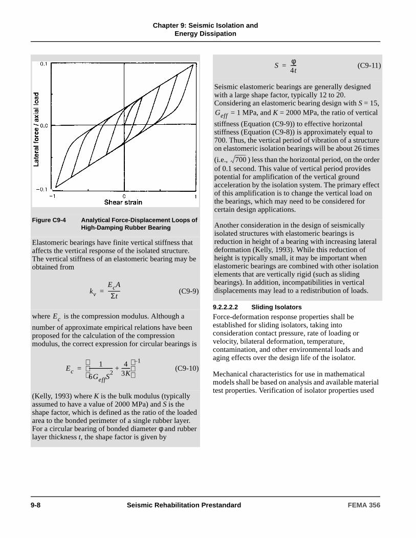
The behavior of the bearing for which the force-displacement loops are shown in Figure C9-2 is now analytically constructed using the mechanical properties at a shear strain of 1.0 and a bearing pressure of 7.0 MPa. These properties are Geff = 0.50 MPa and
= 0.16. With the bonded area and total thickness of
rubber known, and assuming , a bilinear
hysteretic model was defined and implemented in the program 3D-BASIS. The simulated loops are shown in Figure C9-4, where it may be observed that the calculated hysteresis loop at shear strain of 1.0 agrees well with the corresponding experimental hysteresis loop. However, at lower peak shear strain the analytical loops have a constant characteristic strength, whereas the experimental loops have a characteristic strength dependent on the shear strain amplitude. Nevertheless, the analytical model will likely produce acceptable results when the design parameters are based on the mechanical properties at a strain corresponding to the design displacement.
Geff
Geff
keffΣt
A--------------=
βeff
Dy 0.1Σt=
FEMA 356 Seismic Rehabilitation Prestandard 9-7
Chapter 9: Seismic Isolation and
Energy Dissipation
9.2.2.2.2 Sliding Isolators
Force-deformation response properties shall be established for sliding isolators, taking into consideration contact pressure, rate of loading or velocity, bilateral deformation, temperature, contamination, and other environmental loads and aging effects over the design life of the isolator.
Mechanical characteristics for use in mathematical models shall be based on analysis and available material test properties. Verification of isolator properties used
Figure C9-4 Analytical Force-Displacement Loops of High-Damping Rubber Bearing
Elastomeric bearings have finite vertical stiffness that affects the vertical response of the isolated structure. The vertical stiffness of an elastomeric bearing may be obtained from
(C9-9)
where is the compression modulus. Although a
number of approximate empirical relations have been proposed for the calculation of the compression modulus, the correct expression for circular bearings is
(C9-10)
(Kelly, 1993) where K is the bulk modulus (typically assumed to have a value of 2000 MPa) and S is the shape factor, which is defined as the ratio of the loaded area to the bonded perimeter of a single rubber layer. For a circular bearing of bonded diameter φ and rubber layer thickness t, the shape factor is given by
kv
EcA
Σt----------=
Ec
Ec1
6GeffS2
------------------- 43K-------+
1–
=
(C9-11)
Seismic elastomeric bearings are generally designed with a large shape factor, typically 12 to 20. Considering an elastomeric bearing design with S = 15,
= 1 MPa, and K = 2000 MPa, the ratio of vertical
stiffness (Equation (C9-9)) to effective horizontal stiffness (Equation (C9-8)) is approximately equal to 700. Thus, the vertical period of vibration of a structure on elastomeric isolation bearings will be about 26 times
(i.e., ) less than the horizontal period, on the order of 0.1 second. This value of vertical period provides potential for amplification of the vertical ground acceleration by the isolation system. The primary effect of this amplification is to change the vertical load on the bearings, which may need to be considered for certain design applications.
Another consideration in the design of seismically isolated structures with elastomeric bearings is reduction in height of a bearing with increasing lateral deformation (Kelly, 1993). While this reduction of height is typically small, it may be important when elastomeric bearings are combined with other isolation elements that are vertically rigid (such as sliding bearings). In addition, incompatibilities in vertical displacements may lead to a redistribution of loads.
Sφ4t-----=
Geff
700
9-8 Seismic Rehabilitation Prestandard FEMA 356
Chapter 9: Seismic Isolation and
Energy Dissipation
for design shall be based on tests of isolator prototypes in accordance with Section 9.2.9.
C9.2.2.2.2 Sliding Isolators
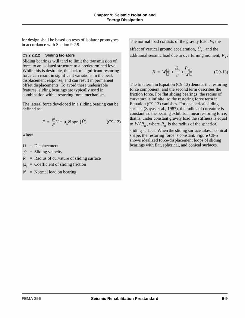
Sliding bearings will tend to limit the transmission of force to an isolated structure to a predetermined level. While this is desirable, the lack of significant restoring force can result in significant variations in the peak displacement response, and can result in permanent offset displacements. To avoid these undesirable features, sliding bearings are typically used in combination with a restoring force mechanism.
The lateral force developed in a sliding bearing can be defined as:
(C9-12)
where
FNR----U + µsN sgn U·( )=
U = Displacement= Sliding velocity
R = Radius of curvature of sliding surface= Coefficient of sliding friction
N = Normal load on bearing
U·
µs
The normal load consists of the gravity load, W, the
effect of vertical ground acceleration, , and the
additional seismic load due to overturning moment, :
(C9-13)
The first term in Equation (C9-13) denotes the restoring force component, and the second term describes the friction force. For flat sliding bearings, the radius of curvature is infinite, so the restoring force term in Equation (C9-13) vanishes. For a spherical sliding surface (Zayas et al., 1987), the radius of curvature is constant, so the bearing exhibits a linear restoring force; that is, under constant gravity load the stiffness is equal to , where is the radius of the spherical
sliding surface. When the sliding surface takes a conical shape, the restoring force is constant. Figure C9-5 shows idealized force-displacement loops of sliding bearings with flat, spherical, and conical surfaces.
U·· v
Ps
N W 1U·· v
g------
Ps
W-----+ +
=
W Ro⁄ Ro
FEMA 356 Seismic Rehabilitation Prestandard 9-9

Chapter 9: Seismic Isolation and
Energy DissipationFigure C9-5 Idealized Force Displacement Loops of Sliding Bearings
Sliding bearings with either a flat or single curvature spherical sliding surface are typically made of PTFE or PTFE-based composites in contact with polished stainless steel. The shape of the sliding surface allows large contact areas that, depending on the materials used, are loaded to average bearing pressures in the range of 7 to 70 MPa. For interfaces with shapes other than flat or spherical, the load needs to be transferred through a bearing as illustrated in Figure C9-5 for the conical sliding surface. Such an arrangement typically results in a very low coefficient of friction.
For bearings with large contact area, and in the absence of liquid lubricants, the coefficient of friction depends on a number of parameters, of which the three most important are the composition of the sliding interface, bearing pressure, and velocity of sliding. For interfaces composed of polished stainless steel in contact with PTFE or PTFE-based composites, the coefficient of sliding friction may be described by
(C9-14)µs fmax - fmax fmin–( ) exp a– U·( )=
where parameters and describe the
coefficient of friction at small and large velocities of sliding and under constant pressure, respectively, all as depicted in Figure C9-6. Parameters , , and a
depend on the bearing pressure, although only the dependency of fmax on pressure is of practical significance. A good approximation to the experimental data (Constantinou et al., 1993b) is
(C9-15)
where the physical significance of parameters
and is as illustrated in Figure C9-6. The term p is
the instantaneous bearing pressure, which is equal to the normal load N computed by Equation (C9-13), divided by the contact area; and ε is a parameter that controls the variation of with pressure.
fmin fmax
fmax fmin
fmax fmaxo fmaxo fmaxp–( ) εptanh–=
fmaxo
fmaxp
fmax
9-10 Seismic Rehabilitation Prestandard FEMA 356

Chapter 9: Seismic Isolation and
Energy Dissipation
9.2.2.3 Modeling of Isolators
9.2.2.3.1 General
If the mechanical characteristics of a seismic isolator are dependent on axial load (due to gravity, earthquake overturning effects, and vertical earthquake shaking), rate of loading (velocity), bilateral deformation, temperature, or aging, then upper- and lower-bound values of stiffness and damping shall be used in multiple analyses of the model to determine the range and sensitivity of response to design parameters.
9.2.2.3.2 Linear Models
The restoring force, F, of an isolator shall be calculated as the product of effective stiffness, keff, and response displacement, D:
(9-1)
The effective stiffness, keff , of an isolator shall be calculated from test data using Equation (9-12). The area enclosed by the force-displacement hysteresis loop shall be used to calculate the effective damping, βeff, of an isolator using Equation (9-13). Effective stiffness and effective damping shall be evaluated at all response displacements of design interest.
Figure C9-6 illustrates another feature of sliding bearings. On initiation of motion, the coefficient of friction exhibits a static or breakaway value, , which
is typically higher than the minimum value . To
demonstrate frictional properties, Figure C9-6 shows the relation between bearing pressure and the friction coefficients , , and of a PTFE-based
composite material in contact with polished stainless steel at normal temperature. These data were compiled from testing of bearings in four different testing programs (Soong and Constantinou, 1994).
Figure C9-6 Coefficient of Friction of PTFE-based Composite in Contact with Polished Stainless Steel at Normal Temperature
Combined elastomeric-sliding isolation systems have been used in buildings in the United States. Japanese engineers have also used elastomeric bearings in combination with mild steel elements that are designed to yield in strong earthquakes and enhance the energy dissipation capability of the isolation system (Kelly, 1988). These mild steel elements exhibit either elasto-plastic behavior or bilinear hysteretic behavior with low post-yielding stiffness. Moreover, fluid viscous energy dissipation devices have been used in combination with elastomeric bearings. The behavior of fluid viscous devices is described in Section 9.3.3.2.3.
µB
fmin
fmax µB fmin
Hybrid seismic isolation systems composed of elastomeric and sliding bearings should be modeled taking into account the likely significant differences in the relationships between vertical displacement as a function of horizontal displacement. The use of elastomeric and sliding isolators in close proximity to one another under vertically stiff structural framing elements (e.g., reinforced concrete shear walls) may be problematic and could result in significant redistributions of gravity loads.
C9.2.2.3.2 Linear Models
Linear procedures use effective stiffness, keff , and effective damping, βeff, to characterize nonlinear properties of isolators.
For linear procedures (see FEMA 274 Section C9.2.3), the seismic isolation system can be represented by an equivalent linearly elastic model. The force in a seismic isolation device is calculated as:
(C9-16)
F keffD=
F keffD=
FEMA 356 Seismic Rehabilitation Prestandard 9-11

Chapter 9: Seismic Isolation and
Energy Dissipation
where all terms are as defined in Section 9.2.2.3.2 of this standard. The effective stiffness of the seismic isolation device may be calculated from test data as follows:
(C9-17)
Figure C9-7 illustrates the physical significance of the effective stiffness.
Analysis by a linear method requires that either each seismic isolator or groups of seismic isolators be represented by linear springs of either stiffness keff or the combined effective stiffness of each group. The energy dissipation capability of an isolation system is generally represented by effective damping. Effective damping is amplitude-dependent and calculated at design displacement, D, as follows:
(C9-18)
where is the sum of the areas of the hysteresis
loops of all isolators, and is the sum of the
effective stiffnesses of all seismic isolation devices. Both the area of the hysteresis loops and the effective stiffness are determined at the design displacement, D.
keffF+ F–+
∆+ ∆–+-------------------------=
βeff1
2π------
ΣED
KeffD2
-----------------=
ΣED
Keff
Figure C9-7 Definition of Effective Stiffness of Seismic Isolation Devices
The application of Equations (C9-16) through (C9-18) to the design of isolation systems is complicated if the effective stiffness and loop area depend on axial load. Multiple analyses are then required to establish bounds on the properties and response of the isolators. For example, sliding isolation systems exhibit such dependencies as described in Section C9.2.2.2.2. To account for these effects, the following procedure is proposed.
9-12 Seismic Rehabilitation Prestandard FEMA 356

Chapter 9: Seismic Isolation and
Energy Dissipation
9.2.2.3.3 Nonlinear Models
The nonlinear force-deflection properties of isolators shall be explicitly modeled if nonlinear procedures are used.
The inelastic (hysteretic) response of the isolators shall represent damping. Additional viscous damping shall not be included in the model unless supported by rate-dependent tests of isolators.
In sliding isolation systems, the relation between horizontal force and vertical load is substantially linear (see Equation (C9-16)). Accordingly, the net effect of overturning moment on the mechanical behavior of a group of bearings is small and can be neglected. Al-Hussaini et al. (1994) provided experimental results that demonstrate this behavior up to the point of imminent bearing uplift. Similar results are likely for elastomeric bearings.
1. The effect of vertical ground acceleration is to modify the load on the isolators. If it is assumed that the building is rigid in the vertical direction, and axial forces due to overturning moments are absent,
the axial loads can vary between and
, where is the peak vertical ground acceleration. However, recognizing that horizontal and vertical ground motion components are likely not correlated unless in the near field, it is appropriate to use a combination rule that uses only a fraction of the peak vertical ground acceleration. Based on the use of 50% of the peak vertical ground acceleration, maximum and minimum axial loads on a given isolator may be defined as:
(C9-19)
where the plus sign gives the maximum value and the minus sign gives the minimum value. Equation (C9-19) is based on the assumption that the short-period spectral response parameter, SDS, is 2.5 times the peak value of the vertical ground acceleration. For analysis for the Maximum Considered Earthquake, the axial load should be determined from
(C9-20)
Equations (C9-19) and (C9-20) should be used with caution if the building is located in the near field of a major active fault. In this instance, expert advice should be sought regarding correlation of horizontal and vertical ground motion components.
W 1 U·· g⁄–( )
W 1 U·· g⁄+( ) U··
Nc W 1 0.20± SDS( )=
Nc W 1 0.20± SMS( )=
Load represents a constant load on isolators, which
can be used for determining the effective stiffness and area of the hysteresis loop. To obtain these properties, the characteristic strength Q (see Figure C9-7) is needed. For sliding isolators, Q can be taken as equal to
, where is determined at the bearing
pressure corresponding to load . For example, for a
sliding bearing with spherical sliding surface of radius (see Figure C9-5), the effective stiffness and area of
the loop at the design displacement D are:
(C9-21)
(C9-22)
C9.2.2.3.3 Nonlinear Models
For dynamic nonlinear time history analysis, the seismic isolation elements should be explicitly modeled. FEMA 274 Sections C9.2.2.2 through C9.2.2.4 present relevant information. When uncertainties exist, and when aspects of behavior cannot be modeled, multiple analyses should be performed in order to establish bounds on the dynamic response.
Nc
fmaxNc fmax
Nc
Ro
keff1
Ro------
fmax
D----------+
Nc=
Loop Area 4fmaxNcD=
FEMA 356 Seismic Rehabilitation Prestandard 9-13

Chapter 9: Seismic Isolation and
Energy Dissipation
9.2.2.4 Isolation System and Superstructure Modeling
9.2.2.4.1 General
Mathematical models of the isolated building, including the isolation system, the lateral-force-resisting system of the superstructure, other structural components and elements, and connections between the isolation system and the structure, shall meet the requirements of Chapters 2 and 3 and Sections 9.2.2.4.2 and 9.2.2.4.3.
9.2.2.4.2 Isolation System Model
The isolation system shall be modeled using deformation characteristics developed and verified by test in accordance with the requirements of Section 9.2.9.
The isolation system shall be modeled with sufficient detail to:
1. Account for the spatial distribution of isolator units.
2. Calculate translation, in both horizontal directions, and torsion of the structure above the isolation interface, considering the most disadvantageous location of mass eccentricity.
3. Assess overturning/uplift forces on individual isolators.
4. Account for the effects of vertical load, bilateral load, and/or the rate of loading, if the force deflection properties of the isolation system are dependent on one or more of these factors.
5. Assess forces due to P-∆ moments.
6. Account for nonlinear components. Isolation systems with nonlinear components include systems that do not meet the criteria of Section 9.2.3.3.1, Item 2.
9.2.2.4.3 Superstructure Model
The maximum displacement of each floor, the total design displacement, and the total maximum displacement across the isolation system shall be calculated using a model of the isolated building that incorporates the force-deformation characteristics of nonlinear components.
Calculation of design forces and displacements in primary components of the lateral-force-resisting system using linearly elastic models of the isolated structure shall be permitted if both of the following criteria are met:
1. Pseudo-elastic properties assumed for nonlinear isolation system components are based on the maximum effective stiffness of the isolation system.
2. The lateral-force-resisting system remains linearly elastic for the earthquake demand level of interest.
A lateral-force-resisting system that meets both of the following criteria may be classified as linearly elastic:
1. For all deformation-controlled actions, Equation (3-20) is satisfied using an m-factor equal to 1.0.
For simplified nonlinear analysis, each seismic isolation element can be modeled by an appropriate rate-independent hysteretic model. Elastomeric bearings may be modeled as bilinear hysteretic elements as described in FEMA 274 Section C9.2.2.2. Sliding bearings may also be modeled as bilinear hysteretic elements with characteristic strength (see Figure C9-5) given by
(C9-23)
where is determined by either Equation (C9-19) or
Equation (C9-20), and is the coefficient of sliding
friction at the appropriate sliding velocity. The post-yield stiffness can then be determined as:
(C9-24)
where R is as defined in FEMA 274 Section C9.2.2.2.B. The yield displacement Dy in a bilinear hysteretic model of a sliding bearing should be very small, perhaps on the order of 2 mm. Alternatively, a bilinear hysteretic model for sliding bearings may be defined to have an elastic stiffness that is at least 100 times larger than the post-yield stiffness .
Isolation devices that exhibit viscoelastic behavior as shown in Figure C9-7 should be modeled as linearly elastic elements with effective stiffness as
determined by Equation (C9-21).
Q fmaxNc=
Nc
fmax
kp
Nc
R------=
kp
keff
9-14 Seismic Rehabilitation Prestandard FEMA 356

Chapter 9: Seismic Isolation and
Energy Dissipation
2. For all force-controlled actions, Equation (3-21) is satisfied.
9.2.3 General Criteria for Seismic Isolation Design
9.2.3.1 General
The design, analysis, and testing of the isolation system shall be based on the requirements of this section.
9.2.3.1.1 Stability of the Isolation System
The stability of the vertical load-carrying components of the isolation system shall be verified by analysis and test, as required by Section 9.2.9, for a lateral displacement equal to the total maximum displacement computed in accordance with Section 9.2.4.3.5 or Section 9.2.5.1.2, or for the maximum displacement allowed by displacement-restraint devices, if such devices are part of the isolation system.
9.2.3.1.2 Configuration Requirements
The isolated building shall be classified as regular or irregular, as defined in Section 2.4.1.1, based on the structural configuration of the structure above the isolation system.
9.2.3.2 Ground Shaking Criteria
Ground shaking criteria for the Design Earthquake and the Maximum Considered Earthquake shall be established in accordance with Section 1.6 as modified by this section. The design Earthquake Hazard Level shall be user-specified and shall be permitted to be chosen equal to the BSE-1 Earthquake Hazard Level. The Maximum Considered Earthquake shall be taken equal to the BSE-2 Earthquake Hazard Level.
9.2.3.2.1 User-Specified Design Earthquake
For the Design Earthquake, the following ground shaking criteria shall be established:
1. Short period spectral response acceleration parameter, SXS and spectral response acceleration parameter at 1.0 second, SX1, in accordance with Section 1.6.1.4.
2. Five-percent-damped response spectrum of the design earthquake (when a response spectrum is required for linear procedures by Section 9.2.3.3.2, or to define acceleration time histories).
3. At least three acceleration time histories compatible with the design earthquake spectrum (when acceleration time histories are required for nonlinear procedures by Section 9.2.3.3.3).
9.2.3.2.2 Maximum Considered Earthquake
For the BSE-2, the following ground shaking criteria shall be established:
1. Short period spectral response acceleration parameter, SXS and spectral response acceleration parameter at 1.0 second, SX1, in accordance with Section 1.6.1.4.
2. Five-percent-damped site-specific response spectrum of the BSE-2 (when a response spectrum is required for linear procedures by Section 9.2.3.3.2, or to define acceleration time histories).
3. At least three acceleration time histories compatible with the BSE-2 spectrum (when acceleration time histories are required for nonlinear procedures by Section 9.2.3.3.3).
9.2.3.3 Selection of Analysis Procedure
9.2.3.3.1 Linear Procedures
Linear procedures shall be permitted for design of seismically isolated buildings, provided the following criteria are met.
1. The building is located on Soil Profile Type A, B, C, or D; or E if for BSE-2.
2. The isolation system meets all of the following criteria:
2.1. The effective stiffness of the isolation system at the design displacement is greater than one-third of the effective stiffness at 20% of the design displacement.
C9.2.3.1 General
Criteria for the seismic isolation of buildings are divided into two sections:
1. Rehabilitation of the building.
2. Design, analysis, and testing of the isolation system.
S1 0.6≥
FEMA 356 Seismic Rehabilitation Prestandard 9-15

Chapter 9: Seismic Isolation and
Energy Dissipation
2.2. The isolation system is capable of producing a restoring force as specified in Section 9.2.7.2.4.
2.3. The isolation system has force-deflection properties that are independent of the rate of loading.
2.4. The isolation system has force-deflection properties that are independent of vertical load and bilateral load.
2.5. When considering analysis procedures, for the BSE-2, the isolation system does not limit BSE-2 displacement to less than the ratio of the design spectral response acceleration at one second (SX1) for the BSE-2 to that for the Design Earthquake times the total design displacement.
3. The structure above the isolation system exhibits global elastic behavior for the earthquake motions under consideration.
9.2.3.3.2 Response Spectrum Analysis
Response spectrum analysis shall be used for design of seismically isolated buildings that meet any of the following criteria.
1. The building is over 65 feet (19.8 meters) in height.
2. The effective period of the structure, TM, is greater than three seconds.
3. The effective period of the isolated structure, TD, is less than or equal to three times the elastic, fixed-base period of the structure above the isolation system.
4. The structure above the isolation system is irregular in configuration.
9.2.3.3.3 Nonlinear Procedures
Nonlinear procedures shall be used for design of seismic-isolated buildings for which any of the following conditions apply:
1. The structure above the isolation system is nonlinear for the earthquake motions under consideration.
2. The isolation system does not meet all of the criteria of Section 9.2.3.3.1.
Nonlinear acceleration time history analysis shall be performed for the design of seismically isolated buildings for which conditions (1) and (2) apply.
C9.2.3.3 Selection of Analysis Procedure
Linear procedures include prescriptive formulas and Response Spectrum Analysis. Linear procedures based on formulas (similar to the seismic-coefficient equation required for design of fixed-base buildings) prescribe peak lateral displacement of the isolation system, and define “minimum” design criteria that may be used for design of a very limited class of isolated structures (without confirmatory dynamic analyses). These simple formulas are useful for preliminary design and provide a means of expeditious review of more complex calculations.
Response Spectrum Analysis is recommended for design of isolated structures that have either (1) a tall or otherwise flexible superstructure, or (2) an irregular superstructure. For most buildings, Response Spectrum Analysis will not predict significantly different displacements of the isolation system than those calculated by prescriptive formulas, provided both calculations are based on the same effective stiffness and damping properties of the isolation system. The real benefit of Response Spectrum Analysis is not in the prediction of isolation system response, but rather in the calculation and distribution of forces in the superstructure. Response Spectrum Analysis permits the use of more detailed models of the superstructure that better estimate forces and deformations of components and elements considering flexibility and irregularity of the structural system.
Nonlinear procedures include the Nonlinear Static Procedure (NSP) and the Nonlinear Dynamic Procedure (NDP). The NSP is a static pushover procedure, and the NDP is based on nonlinear Time History Analysis. The NSP or the NDP is required for isolated structures that do not have essentially linearly elastic superstructures (during BSE-2 demand). In this case, the superstructure would be modeled with nonlinear elements and components.
9-16 Seismic Rehabilitation Prestandard FEMA 356

Chapter 9: Seismic Isolation and
Energy Dissipation
9.2.4 Linear Procedures
9.2.4.1 General
Seismically isolated buildings for which linear analysis procedures are selected based on the criteria of Section 9.2.3.3 shall be designed and constructed to resist the earthquake displacements and forces specified in this section, at a minimum.
9.2.4.2 Deformation Characteristics of the Isolation System
The deformation characteristics of the isolation system shall be based on tests performed in accordance with Section 9.2.9.
The deformation characteristics of the isolation system shall explicitly include the effects of the wind-restraint and tie-down systems, and supplemental energy-dissipation devices, if such systems and devices are used to meet the design requirements of this standard.
9.2.4.3 Minimum Lateral Displacements
9.2.4.3.1 Design Displacement
The isolation system shall be designed and constructed to withstand, as a minimum, lateral earthquake displacements that act in the direction of each of the main horizontal axes of the structure in accordance with Equation (9-2):
(9-2)
where:
SX1 is evaluated for the Design Earthquake.
9.2.4.3.2 Effective Period at the Design Displacement
The effective period, TD, of the isolated building at the design displacement shall be determined using the deformation characteristics of the isolation system in accordance with Equation (9-3):
(9-3)
9.2.4.3.3 Maximum Displacement
The maximum displacement of the isolation system, DM, in the most critical direction of horizontal response shall be calculated in accordance with Equation (9-4):
(9-4)
where:
Time History Analysis is required for isolated structures on very soft soil (i.e., Soil Profile Type E when shaking is strong, or Soil Profile Type F) that could shake the building with a large number of cycles of long-period motion, and for buildings with isolation systems that are best characterized by nonlinear models. Such isolation systems include:
1. Systems with more than about 30% effective damping (because high levels of damping can significantly affect higher-mode response of the superstructure).
2. Systems that lack significant restoring force (because these systems may not stay centered during earthquake shaking).
3. Systems that are expected to exceed the sway-space clearance with adjacent structures (because impact with adjacent structures could impose large demands on the superstructure).
4. Systems that are rate- or load-dependent (because their properties will vary during earthquake shaking).
For the types of isolation systems described above, appropriate nonlinear properties must be used to model isolators. Linear properties could be used to model the superstructure, provided the superstructure’s response is essentially linearly elastic for BSE-2 demand.
The restrictions placed on the use of linear procedures effectively suggest that nonlinear procedures be used for virtually all isolated buildings. However, lower-bound limits on isolation system design displacement and force are specified by this standard as a percentage of the demand prescribed by the linear formulas, even when dynamic analysis is used as the basis for design. These lower-bound limits on key design attributes ensure consistency in the design of isolated structures and serve as a “safety net” against gross underdesign.
DDg
4π2---------
SX1TD
BD1----------------=
TD 2π WKDming------------------=
DMg
4π2---------
SX1TM
BM1----------------=
FEMA 356 Seismic Rehabilitation Prestandard 9-17

Chapter 9: Seismic Isolation and
Energy Dissipation
SX1 is evaluated for the BSE-2.
9.2.4.3.4 Effective Period at the Maximum Displacement
The effective period, TM, of the isolated building at the maximum displacement shall be determined using the deformation characteristics of the isolation system in accordance with Equation (9-5):
(9-5)
9.2.4.3.5 Total Displacement
The total design displacement, DTD, and the total maximum displacement, DTM, of components of the isolation system shall include additional displacement due to actual and accidental torsion calculated considering the spatial distribution of the effective stiffness of the isolation system at the design displacement and the most disadvantageous location of mass eccentricity.
The total design displacement, DTD, and the total maximum displacement, DTM, of components of an isolation system with a uniform spatial distribution of effective stiffness at the design displacement shall be taken as not less than that prescribed by Equations (9-6) and (9-7):
(9-6)
(9-7)
A value for the total maximum displacement, DTM, less than the value prescribed by Equation (9-7), but not less than 1.1 times DM, shall be permitted, provided the isolation system is shown by calculation to be configured to resist torsion.
9.2.4.4 Minimum Lateral Forces
9.2.4.4.1 Isolation System and Structural Components and Elements at or below the Isolation System
The isolation system, the foundation, and all other structural components and elements below the isolation
system shall be designed and constructed to withstand a minimum lateral seismic force, Vb, prescribed by Equation (9-8):
(9-8)
9.2.4.4.2 Structural Components and Elements above the Isolation System
The components and elements above the isolation system shall be designed and constructed to resist a minimum lateral seismic force, Vs , equal to the value of Vb, prescribed by Equation (9-8).
9.2.4.4.3 Limits on Vs
The value of Vs shall be taken as not less than the following:
1. The base shear corresponding to the design wind load.
2. The lateral seismic force required to fully activate the isolation system factored by 1.5.
9.2.4.4.4 Vertical Distribution of Force
The total force, Vs, shall be distributed over the height of the structure above the isolation interface in accordance with Equation (9-9):
(9-9)
At each level designated as x, the force Fx shall be applied over the area of the building in accordance with the weight, wx, distribution at that level, hx. Response of structural components and elements shall be calculated as the effect of the force Fx applied at the appropriate levels above the base.
TM 2π WKMming-------------------=
DTD DD 1 y12e
b2
d2
+-----------------+=
DTM DM 1 y12e
b2
d2
+-----------------+=
C9.2.4.4.3 Limits on Vs
Examples of lateral seismic forces required to fully activate the isolation system include the yield level of a softening system, the ultimate capacity of a sacrificial wind-restraint system, or the break-away friction level of a sliding system.
Vb KDmaxDD=
Fx
Vswxhx
wihi
n
∑---------------------=
9-18 Seismic Rehabilitation Prestandard FEMA 356

Chapter 9: Seismic Isolation and
Energy Dissipation
9.2.4.5 Response Spectrum Analysis
9.2.4.5.1 Earthquake Input
The Design Earthquake spectrum shall be used to calculate the total design displacement of the isolation system and the lateral forces and displacements of the isolated building. The BSE-2 spectrum shall be used to calculate the total maximum displacement of the isolation system.
9.2.4.5.2 Modal Damping
Response spectrum analysis shall be performed, using a damping value for isolated modes equal to the effective damping of the isolation system, or 30% of critical, whichever is less. The damping value assigned to higher modes of response shall be consistent with the material type and stress level of the superstructure.
9.2.4.5.3 Combination of Earthquake Directions
Response spectrum analysis used to determine the total design displacement and total maximum displacement shall include simultaneous excitation of the model by 100% of the most critical direction of ground motion, and not less than 30% of the ground motion in the orthogonal axis. The maximum displacement of the isolation system shall be calculated as the vector sum of the two orthogonal displacements.
9.2.4.5.4 Scaling of Results
If the total design displacement determined by response spectrum analysis is found to be less than the value of DTD prescribed by Equation (9-6), or if the total maximum displacement determined by response spectrum analysis is found to be less than the value of DTM prescribed by Equation (9-7), then all response parameters, including component actions and deformations, shall be adjusted upward proportionally to the DTD value, or the DTM value, whichever is greater, and used for design.
9.2.4.6 Design Forces and Deformations
Components and elements of the building shall be designed for forces and displacements estimated by linear procedures using the acceptance criteria of Section 3.4.2.2, except that deformation-controlled components and elements shall be designed using component m-factors equal to or less than 1.5.
9.2.5 Nonlinear Procedures
Seismically isolated buildings evaluated using nonlinear procedures shall be represented by three-
dimensional models that incorporate the nonlinear characteristics of both the isolation system and the structure above the isolation system.
9.2.5.1 Nonlinear Static Procedure
9.2.5.1.1 General
The Nonlinear Static Procedure (NSP) for seismically isolated buildings shall be based on the criteria of Section 3.3.3, except that the target displacement and pattern of applied lateral load shall be based on the criteria given in Sections 9.2.5.1.2 and 9.2.5.1.3, respectively.
9.2.5.1.2 Target Displacement
In each principal direction, the building model shall be pushed to the Design Earthquake target displacement,
, and to the BSE-2 target displacement, , as
defined by Equations (9-10) and (9-11):
(9-10)
(9-11)
where Te is the effective period of the structure above the isolation interface on a fixed base as prescribed by Equation (3-14). The target displacements, and ,
shall be evaluated at a control node that is located at the center of mass of the first floor above the isolation interface.
9.2.5.1.3 Lateral Load Pattern
The pattern of applied lateral load shall be proportional to the distribution of the product of building mass and the deflected shape of the isolated mode of response at the target displacement.
9.2.5.2 Nonlinear Dynamic Procedure
9.2.5.2.1 General
The Nonlinear Dynamic Procedure (NDP) for seismically isolated buildings shall be based on the nonlinear procedure requirements of Section 3.3.4,
D ′D D ′M
D ′DDD
1Te
TD-------
2
+
-----------------------------=
D ′MDM
1Te
TM-------
2
+
-----------------------------=
D ′D D ′M
FEMA 356 Seismic Rehabilitation Prestandard 9-19

Chapter 9: Seismic Isolation and
Energy Dissipation
except that results shall be scaled for design based on the criteria given in the following section.
9.2.5.2.2 Scaling of Results
If the design displacement determined by time-history analysis is less than the value of prescribed by
Equation (9-10), or if the maximum displacement determined by response spectrum analysis is found to be less than the value of prescribed by Equation
(9-11), then all response parameters, including component actions and deformations, shall be adjusted upward proportionally to the value or the
value, whichever is greater, and used for design.
9.2.5.3 Design Forces and Deformations
Components and elements of the building shall be designed for the forces and deformations estimated by nonlinear procedures using the acceptance criteria of Section 3.4.3.2.
9.2.6 Nonstructural Components
9.2.6.1 General
Permanent nonstructural components and the attachments to them shall be designed to resist seismic forces and displacements as given in this section and the applicable requirements of Chapter 11.
9.2.6.2 Forces and Displacements
9.2.6.2.1 Components and Elements at or above the Isolation Interface
Nonstructural components, or portions thereof, that are at or above the isolation interface, shall be designed to resist a total lateral seismic force equal to the maximum dynamic response of the element or component under consideration.
EXCEPTION: Design of elements of seismically isolated structures and nonstructural components, or portions thereof, to resist the total lateral seismic force as required for conventional fixed-base buildings by Chapter 11, shall be permitted.
9.2.6.2.2 Components and Elements that Cross the Isolation Interface
Nonstructural components, or portions thereof, that cross the isolation interface shall be designed to withstand the total maximum (horizontal) displacement and maximum vertical displacement of the isolation
system at the total maximum (horizontal) displacement. Components and elements that cross the isolation interface shall not restrict displacement of the isolated building or otherwise compromise the Rehabilitation Objectives of the building.
9.2.6.2.3 Components and Elements below the Isolation Interface
Nonstructural components, or portions thereof, that are below the isolation interface shall be designed and constructed in accordance with the requirements of Chapter 11.
9.2.7 Detailed System Requirements
9.2.7.1 General
The isolation system and the structural system shall comply with the detailed system requirements specified in Section 9.2.7.2 and 9.2.7.3, respectively.
9.2.7.2 Isolation System
9.2.7.2.1 Environmental Conditions
In addition to the requirements for vertical and lateral loads induced by wind and earthquake, the isolation system shall be designed with consideration given to other environmental conditions, including aging effects, creep, fatigue, operating temperature, and exposure to moisture or damaging substances.
9.2.7.2.2 Wind Forces
Isolated buildings shall resist design wind loads at all levels above the isolation interface in accordance with the applicable wind design provisions. At the isolation interface, a wind-restraint system shall be provided to limit lateral displacement in the isolation system to a value equal to that required between floors of the structure above the isolation interface.
9.2.7.2.3 Fire Resistance
Fire resistance rating for the isolation system shall be consistent with the requirements of columns, walls, or other such elements of the building.
9.2.7.2.4 Lateral Restoring Force
The isolation system shall be configured to produce either a restoring force such that the lateral force at the total design displacement is at least 0.025W greater than the lateral force at 50% of the total design displacement, or a restoring force of not less than 0.05W at all displacements greater than 50% of the total design displacement.
D ′D
D ′M
D ′D D ′M
9-20 Seismic Rehabilitation Prestandard FEMA 356

Chapter 9: Seismic Isolation and
Energy Dissipation
EXCEPTION: The isolation system need not be configured to produce a restoring force, as required above, provided the isolation system is capable of remaining stable under full vertical load and accommodating a total maximum displacement equal to the greater of either 3.0 times the total design displacement or 36 SX1 inches, where SX1 is calculated for the BSE-2.
9.2.7.2.5 Displacement Restraint
Configuration of the isolation system to include a displacement restraint that limits lateral displacement due to the BSE-2 to less than the ratio of the design spectral response acceleration parameter at one second (SX1) for the BSE-2 to that for the Design Earthquake times the total design displacement shall be permitted, provided that the seismically isolated building is designed in accordance with the following criteria when more stringent than the requirements of Section 9.2.3.
1. BSE-2 response is calculated in accordance with the dynamic analysis requirements of Section 9.2.5, explicitly considering the nonlinear characteristics of the isolation system and the structure above the isolation system.
2. The ultimate capacity of the isolation system, and structural components and elements below the isolation system, shall exceed the force and displacement demands of the BSE-2.
3. The structure above the isolation system is checked for stability and ductility demand of the BSE-2.
4. The displacement restraint does not become effective at a displacement less than 0.75 times the total design displacement, unless it is demonstrated by analysis that earlier engagement does not result in unsatisfactory performance.
9.2.7.2.6 Vertical Load Stability
Each component of the isolation system shall be designed to be stable under the full maximum vertical load, 1.2QD + QL + |QE|, and the minimum vertical load, 0.8QD - |QE|, at a horizontal displacement equal to the total maximum displacement. The earthquake vertical load on an individual isolator unit, QE, shall be based on peak building response due to the BSE-2.
9.2.7.2.7 Overturning
The factor of safety against global structural overturning at the isolation interface shall be not less than 1.0 for required load combinations. All gravity and seismic loading conditions shall be investigated. Seismic forces for overturning calculations shall be based on the BSE-2, and the vertical restoring force shall be based on the building’s weight, W, above the isolation interface.
Local uplift of individual components and elements shall be permitted, provided the resulting deflections do not cause overstress or instability of the isolator units or other building components and elements. A tie-down system to limit local uplift of individual components and elements shall be permitted, provided that the seismically isolated building is designed in accordance with the following criteria when more stringent than the requirements of Section 9.2.3.
1. BSE-2 response is calculated in accordance with the dynamic analysis requirements of Section 9.2.5, explicitly considering the nonlinear characteristics of the isolation system and the structure above the isolation system.
2. The ultimate capacity of the tie-down system exceeds the force and displacement demands of the BSE-2.
3. The isolation system is designed and shown by test to be stable (Section 9.2.9.2.4) for BSE-2 loads that include additional vertical load due to the tie-down system.
9.2.7.2.8 Inspection and Replacement
Access for inspection and replacement of all components and elements of the isolation system shall be provided.
9.2.7.2.9 Manufacturing Quality Control
A manufacturing quality control testing program for isolator units shall be established by the engineer responsible for the structural design.
9.2.7.3 Structural System
9.2.7.3.1 Horizontal Distribution of Force
A horizontal diaphragm or other structural components and elements shall provide continuity above the isolation interface. The diaphragm or other structural components and elements shall have adequate strength
FEMA 356 Seismic Rehabilitation Prestandard 9-21

Chapter 9: Seismic Isolation and
Energy Dissipation
and ductility to transmit forces (due to non-uniform ground motion) calculated in accordance with this section from one part of the building to another, and have sufficient stiffness to effect rigid diaphragm response above the isolation interface.
9.2.7.3.2 Building Separations
Separations between the isolated building and surrounding retaining walls or other fixed obstructions shall be not less than the total design displacement.
9.2.8 Design Review
9.2.8.1 General
A review of the design of the isolation system and related test programs shall be performed by an independent engineering team, including persons experienced in seismic analysis methods and the theory and application of seismic isolation.
9.2.8.2 Isolation System
Isolation system design review shall include the following:
1. Site-specific seismic criteria, including site-specific spectra and ground motion time history, and all other design criteria developed specifically for the project.
2. Preliminary design, including the determination of the total design and total maximum displacement of the isolation system, and the lateral force design level.
3. Isolation system prototype testing in accordance with Section 9.2.9.
4. Final design of the isolated building and supporting analyses.
5. Isolation system quality control testing in accordance with Section 9.2.7.2.9.
9.2.9 Isolation System Testing and Design Properties
9.2.9.1 General
The deformation characteristics and damping values of the isolation system used in the design and analysis of seismically isolated structures shall be based on the following tests of a selected sample of the components prior to construction.
The isolation system components to be tested shall include isolators and components of the wind restraint system and supplemental energy dissipation devices if such components and devices are used in the design.
The tests specified in this section establish design properties of the isolation system, and shall not be considered as satisfying the manufacturing quality control testing requirements of Section 9.2.7.2.9.
9.2.9.2 Prototype Tests
9.2.9.2.1 General
Prototype tests shall be performed separately on two full-size specimens of each type and size of isolator of the isolation system. The test specimens shall include components of the wind restraint system, as well as individual isolators, if such components are used in the design. Supplementary energy dissipation devices shall be tested in accordance with Section 9.3.8. Specimens tested shall not be used for construction unless approved by the engineer responsible for the structural design.
9.2.9.2.2 Record
For each cycle of tests, the force-deflection and hysteretic behavior of the test specimen shall be recorded.
9.2.9.2.3 Sequence and Cycles
The following sequence of tests shall be performed for the prescribed number of cycles at a vertical load equal to the average QD + 0.5QL on all isolators of a common type and size:
1. Twenty fully reversed cycles of loading at a lateral force corresponding to the wind design force.
2. Three fully reversed cycles of loading at each of the following displacements: 0.25DD, 0.50DD, 1.0DD, and 1.0DM.
3. Three fully reversed cycles at the total maximum displacement, 1.0DTM.
4. 30SX1 / SXSBD1, but not less than 10, fully reversed cycles of loading at the design displacement, 1.0DD. SX1 and SXS shall be evaluated for the Design Earthquake.
9-22 Seismic Rehabilitation Prestandard FEMA 356

Chapter 9: Seismic Isolation and
Energy Dissipation
9.2.9.2.4 Vertical Load-Carrying Isolators
If an isolator is also a vertical-load-carrying element, then Item 2 of the sequence of cyclic tests specified in Section 9.2.9.2.3 shall be performed for two additional vertical load cases:
1. 1.2QD + 0.5QL + |QE|
2. 0.8QD - |QE|
where D, L, and E refer to dead, live, and earthquake loads. QD and QL are as defined in Section 3.2.8. The vertical test load on an individual isolator unit shall include the load increment QE due to earthquake overturning, and shall be equal to or greater than the peak earthquake vertical force response corresponding to the test displacement being evaluated. In these tests, the combined vertical load shall be taken as the typical or average downward force on all isolators of a common type and size.
9.2.9.2.5 Isolators Dependent on Loading Rates
If the force-deflection properties of the isolators are dependent on the rate of loading, then each set of tests specified in Sections 9.2.9.2.3 and 9.2.9.2.4 shall be performed dynamically at a frequency equal to the inverse of the effective period, TD, of the isolated structure.
EXCEPTION: If reduced-scale prototype specimens are used to quantify rate-dependent properties of isolators, the reduced-scale prototype specimens shall be of the same type and material and be manufactured with the same processes and quality as full-scale prototypes, and shall be tested at a frequency that represents full-scale prototype loading rates.
The force-deflection properties of an isolator shall be considered to be dependent on the rate of loading if there is greater than a plus or minus 10% difference in the effective stiffness at the design displacement (1) when tested at a frequency equal to the inverse of the effective period of the isolated structure and (2) when tested at any frequency in the range of 0.1 to 2.0 times the inverse of the effective period of the isolated structure.
9.2.9.2.6 Isolators Dependent on Bilateral Load
If the force-deflection properties of the isolators are dependent on bilateral load, then the tests specified in
Sections 9.2.9.2.3 and 9.2.9.2.5 shall be augmented to include bilateral load at the following increments of the total design displacement: 0.25 and 1.0; 0.50 and 1.0; 0.75 and 1.0; and 1.0 and 1.0.
EXCEPTION: If reduced-scale prototype specimens are used to quantify bilateral-load-dependent properties, then such scaled specimens shall be of the same type and material, and manufactured with the same processes and quality as full-scale prototypes.
The force-deflection properties of an isolator shall be considered to be dependent on bilateral load, if the bilateral and unilateral force-deflection properties have greater than a plus or minus 15% difference in effective stiffness at the design displacement.
9.2.9.2.7 Maximum and Minimum Vertical Load
Isolators that carry vertical load shall be statically tested for the maximum and minimum vertical load, at the total maximum displacement. In these tests, the combined vertical loads of 1.2QD + 1.0QL + |QE| shall be taken as the maximum vertical force, and the combined vertical load of 0. 8QD - |QE| shall be taken as the minimum vertical force, on any one isolator of a common type and size. The earthquake vertical load on an individual isolator, QE, shall be based on peak building response due to the BSE-2.
9.2.9.2.8 Sacrificial Wind-Restraint Systems
If a sacrificial wind-restraint system is part of the isolation system, then the ultimate capacity shall be established by testing in accordance with this section.
9.2.9.2.9 Testing Similar Units
Prototype tests need not be performed if an isolator unit, when compared to another tested unit, complies with the following criteria:
1. Is of similar dimensional characteristics.
2. Is of the same type and materials.
3. Is fabricated using identical manufacturing and quality control procedures.
The testing exemption shall be approved by the review team specified in Section 9.2.8.
FEMA 356 Seismic Rehabilitation Prestandard 9-23

Chapter 9: Seismic Isolation and
Energy Dissipation
9.2.9.3 Determination of Force-Deflection Characteristics
The force-deflection characteristics of the isolation system shall be based on the cyclic load testing of isolator prototypes specified in Section 9.2.9.2.3.
As required, the effective stiffness of an isolator unit, keff, shall be calculated for each cycle of deformation by Equation (9-12):
(9-12)
where and are the positive and negative forces at
positive and negative test displacements, ∆+ and ∆–, respectively.
As required, the effective damping of an isolator unit, βeff, shall be calculated for each cycle of deformation by Equation (9-13):
(9-13)
where the energy dissipated per cycle of loading, ELoop, and the effective stiffness, keff, are based on test
displacements, ∆+ and ∆–.
9.2.9.4 System Adequacy
The performance of the test specimens shall be assessed as adequate if the following conditions are satisfied.
1. The force-deflection plots of all tests specified in Section 9.2.9.2 have a nonnegative incremental force-carrying capacity.
2. For each increment of test displacement specified in Section 9.2.9.2.3, Item 2, and for each vertical load case specified in Section 9.2.9.2.3, the following criteria are met:
2.1. There is no greater than a plus or minus 15% difference between the effective stiffness at each of the three cycles of test and the average value of effective stiffness for each test specimen.
2.2. There is no greater than a 15% difference in the average value of effective stiffness of the two test specimens of a common type and size of the isolator unit over the required three cycles of test.
3. For each specimen there is no greater than a plus or minus 20% change in the initial effective stiffness of each test specimen over the 30SX1/ SXSBD1, but not less than 10, cycles of the test specified in Section 9.2.9.2.3, Item 3. SX1 and SXS shall be evaluated for the Design Earthquake.
4. For each specimen there is no greater than a 20% decrease in the initial effective damping over the 30SX1/ SXSBD1, but not less than 10, cycles of the test specified in Section 9.2.9.2.3, Item 4. SX1 and SXS shall be evaluated for the Design Earthquake.
5. All specimens of vertical-load-carrying elements of the isolation system remain stable at the total maximum displacement for static load as prescribed in Section 9.2.9.2.6.
6. The effective stiffness and effective damping of test specimens fall within the limits specified by the engineer responsible for structural design.
9.2.9.5 Design Properties of the Isolation System
9.2.9.5.1 Maximum and Minimum Effective Stiffness
At the design displacement, the maximum and minimum effective stiffness of the isolation system, KDmax and KDmin, shall be based on the cyclic tests of Section 9.2.9.2 and calculated by Equations (9-14) and (9-15):
(9-14)
(9-15)
At the maximum displacement, the maximum and minimum effective stiffness of the isolation system shall be based on cyclic tests of Section 9.2.9.2 and calculated by Equations (9-16) and (9-17):
keffF
+F
–+
∆+ ∆–+
-------------------------=
F+
F–
βeff2π---
ELoop
keff ∆+ ∆–+( )
2-----------------------------------------=
KDmax
FD+
max FD–
max∑+∑2DD
---------------------------------------------------------=
KDmin
FD+
min FD–
min∑+∑2DD
--------------------------------------------------------=
9-24 Seismic Rehabilitation Prestandard FEMA 356

Chapter 9: Seismic Isolation and
Energy Dissipation
(9-16)
(9-17)
9.2.9.5.2 Effective Damping
At the design displacement, the effective damping of the isolation system, βD, shall be based on the cyclic tests of Section 9.2.9.2 and calculated by Equation (9-18):
(9-18)
In Equation (9-18), the total energy dissipated in the isolation system per displacement cycle, ΣED, shall be taken as the sum of the energy dissipated per cycle in all
isolators measured at test displacements, ∆+ and ∆–, that are equal in magnitude to the design displacement, DD.
At the maximum displacement, the effective damping of the isolation system, βM, shall be based on the cyclic tests of Section 9.2.9.2 and calculated by Equation (9-19):
(9-19)
In Equation (9-19), the total energy dissipated in the isolation system per displacement cycle, ΣEM, shall be taken as the sum of the energy dissipated per cycle in all
isolators measured at test displacements, ∆+ and ∆–, that are equal in magnitude to the maximum displacement, DM.
9.3 Passive Energy Dissipation Systems
9.3.1 General Requirements
Passive energy dissipation systems classified as either displacement-dependent, velocity-dependent, or other, as defined in Section 9.3.3, shall comply with the requirements of Section 9.3. Linear and nonlinear analyses shall be performed, as required, in accordance with Section 9.3.4 and 9.3.5, respectively. Additional requirements for passive energy dissipation systems, as defined in Section 9.3.6, shall be met. Passive energy dissipation systems shall be reviewed and tested in accordance with Sections 9.3.7 and 9.3.8, respectively.
The energy dissipation devices shall be designed with consideration given to environmental conditions including wind, aging effects, creep, fatigue, ambient temperature, operating temperature, and exposure to moisture or damaging substances.
The mathematical model of the rehabilitated building shall include the plan and vertical distribution of the energy dissipation devices. Analyses shall account for the dependence of the devices on excitation frequency, ambient and operating temperature, velocity, sustained loads, and bilateral loads. Multiple analyses of the building shall be conducted to bound the effects of each varying mechanical characteristic of the devices.
Energy dissipation devices shall be capable of sustaining larger displacements for displacement-dependent devices and larger velocities for velocity-dependent devices than the maximum calculated for the BSE-2 in accordance with the following criteria:
1. If four or more energy dissipation devices are provided in a given story of a building in one principal direction of the building, with a minimum of two devices located on each side of the center of stiffness of the story in the direction under consideration, all energy dissipation devices shall be capable of sustaining displacements equal to 130% of the maximum calculated displacement in the device in the BSE-2. A velocity-dependent device as described in Section 9.3.3 shall be capable of sustaining the force associated with a velocity equal to 130% of the maximum calculated velocity for that device in the BSE-2.
KMmax
FM+
max FM–
max∑+∑2DM
----------------------------------------------------------=
KMmin
FM+
min FM–
min∑+∑2DM
---------------------------------------------------------=
βD1
2π------
ED∑KDmaxDD
2------------------------=
βM1
2π------
EM∑KMmaxDM
2-------------------------=
FEMA 356 Seismic Rehabilitation Prestandard 9-25

Chapter 9: Seismic Isolation and
Energy Dissipation
2. If fewer than four energy dissipation devices are provided in a given story of a building in one principal direction of the building, or fewer than two devices are located on each side of the center of stiffness of the story in the direction under consideration, all energy dissipation devices shall be capable of sustaining displacements equal to 200% of the maximum calculated displacement in the device in the BSE-2. A velocity-dependent device shall be capable of sustaining the force associated with a velocity equal to 200% of the maximum calculated velocity for that device in the BSE-2.
The components and connections transferring forces between the energy dissipation devices shall be designed to remain linearly elastic for the forces described in items 1 or 2 above.
9.3.2 Implementation of Energy Dissipation Devices
Energy dissipation devices shall be implemented in accordance with requirements specified in Chapters 1 through 3 but as modified in the subsequent sections of this chapter.
9.3.3 Modeling of Energy Dissipation Devices
Displacement-dependent devices shall include devices that exhibit either rigid-plastic (friction devices), bilinear (metallic yielding devices), or trilinear hysteresis. The response of displacement-dependent devices shall be independent of velocity and frequency of excitation. Velocity-dependent devices shall include solid and fluid viscoelastic devices, and fluid viscous devices. Devices not classified as displacement- or velocity-dependent shall be classified as “other.”
Models of the energy dissipation system shall include the stiffness of structural components that are part of the load path between energy dissipation devices and the ground and whose flexibility affects the performance of
C9.3.1 General Requirements
The increase in displacement (and velocity) capacity is dependent on the level of redundancy in the supplemental damping system.
Passive energy dissipation is an emerging technology that enhances the performance of the building by adding damping (and in some cases, stiffness) to the building. The primary use of energy dissipation devices is to reduce earthquake displacement of the structure. Energy dissipation devices will also reduce force in the structure—provided the structure is responding elastically—but would not be expected to reduce force in structures that are responding beyond yield.
For most applications, energy dissipation provides an alternative approach to conventional stiffening and strengthening schemes, and would be expected to achieve comparable performance levels. In general, these devices would be expected to be good candidates for projects that have a target Building Performance Level of Life Safety or perhaps Immediate Occupancy, but would be expected to have only limited applicability to projects with a target Building Performance Level of Collapse Prevention.
Other objectives may also influence the decision to use energy dissipation devices since these devices can also be useful for control of building response due to small earthquakes, wind, or mechanical loads. The analysis procedures set forth in this standard are approximate. Roof displacements calculated using the linear and nonlinear procedures are likely to be more accurate than the corresponding estimates of interstory drift and relative velocity between adjacent stories. Accordingly, this standard requires that energy dissipation devices be capable of sustaining larger displacements (and velocities for velocity-dependent devices) than the maxima calculated by analysis in the BSE-2. Recognizing that the response of a building frame incorporating four or more devices in each principal direction in each story will be more reliable than a frame with fewer devices in each principal direction, the increase in displacement (and velocity) capacity is dependent on the level of redundancy in the supplemental damping system. The increased force shall be used to design the framing that supports the energy dissipation devices–reflecting the objective of keeping the device support framing elastic in the BSE-2. The increases in force and displacement capacity listed in this standard are based on the judgment of the authors.
9-26 Seismic Rehabilitation Prestandard FEMA 356

Chapter 9: Seismic Isolation and
Energy Dissipation
the energy dissipation system, including components of the foundation, braces that work in series with the energy dissipation devices, and connections between braces and the energy dissipation devices.
Energy dissipation devices shall be modeled as described in the following subsections, unless approved methods are used.
9.3.3.1 Displacement-Dependent Devices
A displacement-dependent device shall have a force-displacement relationship that is a function of the relative displacement between each end of the device. The response of a displacement-dependent device shall be independent of the relative velocity between each end of the device and frequency of excitation.
Displacement-dependent devices shall be modeled in sufficient detail to capture their force- displacement response, and their dependence, if any, on axial-shear-flexure interaction, or bilateral deformation response.
For evaluating the response of a displacement-dependent device from testing data, the force in a displacement-dependent device shall be calculated in accordance with Equation (9-20):
(9-20)
where the effective stiffness, keff, of the device is calculated in accordance with Equation (9-21):
(9-21)
The forces in the device, F+ and F –, shall be evaluated at displacements D+ and D–, respectively.
9.3.3.2 Velocity-Dependent Devices
9.3.3.2.1 Solid Viscoelastic Devices
Solid viscoelastic devices shall be modeled using a spring and dashpot in parallel (Kelvin model). The spring and dashpot constants selected shall capture the frequency and temperature dependence of the device consistent with fundamental frequency of the rehabilitated building (f1), and the operating temperature range. If the cyclic response of a viscoelastic solid device cannot be captured by single estimates of the spring and dashpot constants, the response of the rehabilitated building shall be estimated by multiple analyses of the building frame, using limiting upper- and lower-bound values for the spring and dashpot constants.
The force in a viscoelastic device shall be determined in accordance with Equation (9-22):
(9-22)
where C is the damping coefficient for the viscoelastic device, D is the relative displacement between each end
of the device, is the relative velocity between each end of the device, and keff is the effective stiffness of the device calculated in accordance with Equation (9-23):
(9-23)
where is the storage stiffness.
The damping coefficient for the device shall be calculated in accordance with Equation (9-24):
(9-24)
where is the loss stiffness, the angular frequency ω1 is equal to 2πf1, Dave is the average of the absolute
values of displacements D+ and D–, and WD is the area
C9.3.3 Modeling of Energy Dissipation Devices
Examples of “other” devices include shape- memory alloys (superelastic effect), friction-spring assemblies with recentering capability, and fluid restoring force-damping devices.
F keffD=
keffF
+F
–+
D+
D–
+--------------------------=
F keffD CD·+=
D·
keffF
+F
–+
D+
D–
+-------------------------- K ′= =
K ′
CWD
πω1Dave2
---------------------- K″ω1------= =
K″
FEMA 356 Seismic Rehabilitation Prestandard 9-27

Chapter 9: Seismic Isolation and
Energy Dissipation
enclosed by one complete cycle of the force-displacement response of the device.
9.3.3.2.2 Fluid Viscoelastic Devices
Fluid viscoelastic devices shall be modeled using a spring and dashpot in series (Maxwell model). The spring and dashpot constants selected shall capture the frequency and temperature dependence of the device consistent with fundamental frequency of the rehabilitated building (f1), and the operating temperature range. If the cyclic response of a viscoelastic fluid device cannot be captured by single estimates of the spring and dashpot constants, the response of the rehabilitated building shall be estimated by multiple analyses of the building frame, using limiting upper- and lower-bound values for the spring and dashpot constants.
9.3.3.2.3 Fluid Viscous Devices
Linear fluid viscous dampers exhibiting stiffness in the frequency range 0.5 f1 to 2.0 f1 shall be modeled as a fluid viscoelastic device.
In the absence of stiffness in the frequency range 0.5 f1 to 2.0 f1, the force in the fluid viscous device shall be computed in accordance with Equation (9-25):
(9-25)
where C0 is the damping coefficient for the device, α is
the velocity exponent for the device, is the relative velocity between each end of the device, and sgn is the signum function that, in this case, defines the sign of the relative velocity term.
9.3.3.3 Other Types of Devices
Energy dissipation devices not classified as either displacement-dependent or velocity-dependent shall be modeled using approved methods. Such models shall accurately describe the force-velocity-displacement response of the device under all sources of loading including gravity, seismic, and thermal.
9.3.4 Linear Procedures
Linear procedures shall be permitted only if the following criteria are met:
1. The framing system exclusive of the energy dissipation devices remains linearly elastic for the selected Earthquake Hazard Level after the effects of added damping are considered.
2. The effective damping afforded by the energy dissipation does not exceed 30% of critical in the fundamental mode.
3. The secant stiffness of each energy dissipation device, calculated at the maximum displacement in the device, is included in the mathematical model of the rehabilitated building.
C9.3.3.2.1 Solid Viscoelastic Devices
The cyclic response of viscoelastic solids is generally dependent on the frequency and amplitude of the motion and the operating temperature (including temperature rise due to excitation).
C9.3.3.2.2 Fluid Viscoelastic Devices
The cyclic response of viscoelastic fluid devices is generally dependent on the frequency and amplitude of the motion and the operating temperature (including temperature rise due to excitation).
F C0 D·α
sgn D·( )=
D·
C9.3.3.3 Other Types of Devices
Other energy dissipating devices, such as those having hysteresis of the type shown in Figure C9-8, require modeling techniques different from those described above. Tsopelas and Constantinou (1994a), Nims et al. (1993), and Pekcan et al. (1995) describe analytical models for some of these devices.
Figure C9-8 Idealized Force-Displacement Loops of Energy Dissipation Devices with Recentering Capability
9-28 Seismic Rehabilitation Prestandard FEMA 356

Chapter 9: Seismic Isolation and
Energy Dissipation
4. When evaluating the regularity of a building, the energy dissipation devices are included in the mathematical model.
9.3.4.1 Linear Static Procedure
9.3.4.1.1 Displacement-Dependent Devices
Use of The Linear Static Procedure (LSP) shall be permitted to analyze displacement-dependent energy dissipation devices, provided that in addition to the requirements of Section 9.3.4, the following requirements are satisfied:
1. The ratio of the maximum resistance in each story, in the direction under consideration, to the story shear demand calculated using Equations (3-11) and (3-12), shall range between 80% and 120% of the average value of the ratio for all stories. The maximum story resistance shall include the contributions from all components, elements, and energy dissipation devices.
2. The maximum resistance of all energy dissipation devices in a story, in the direction under consideration, shall not exceed 50% of the resistance of the remainder of the framing where said resistance is calculated at the displacements anticipated in the BSE-2. Aging and environmental effects shall be considered in calculating the maximum resistance of the energy dissipation devices.
The pseudolateral load of Equation (3-10) shall be reduced by the damping modification factors of Table 1-6 to account for the energy dissipation (damping) afforded by the energy dissipation devices. The damping effect shall be calculated in accordance with Equation (9-26):
(9-26)
where β is the damping in the framing system and shall be set equal to 0.05 unless modified in Section 1.6.1.4, Wj shall be taken as the work done by device j in one complete cycle corresponding to floor displacements δi, the summation extends over all devices j, and Wk is the maximum strain energy in the frame, determined using Equation (9-27):
(9-27)
where Fi shall be taken as the inertia force at floor level i and the summation extends over all floor levels.
9.3.4.1.2 Velocity-Dependent Devices
Use of the LSP shall be permitted to analyze velocity-dependent energy dissipation devices, provided that in addition to the requirements of Section 9.3.4, the following requirements are satisfied:
1. The maximum resistance of all energy dissipation devices in a story in the direction under consideration shall not exceed 50% of the resistance of the remainder of the framing where said resistance is calculated at the displacements anticipated in the BSE-2. Aging and environmental effects shall be considered in calculating the maximum resistance of the energy dissipation devices.
2. The pseudolateral load of Equation (3-10) shall be reduced by the damping modification factors of Table 1-6 to account for the energy dissipation (damping) afforded by the energy dissipation devices. The damping effect shall be calculated in accordance with Equation (9-28):
(9-28)
where β is the damping in the structural frame and shall be set equal to 0.05 unless modified in Section 1.6.1.5.3, Wj shall be taken as the work done by device j in one complete cycle corresponding to floor displacements δi, the summation extends over all devices j, and Wk is the maximum strain energy in the frame, determined using Equation (9-27).
The work done by linear viscous device j in one complete cycle of loading shall be calculated in accordance with Equation (9-29):
(9-29)
βeff β
Wjj
∑4πWk--------------+=
Wk12--- Fiδi
i∑=
βeff β
Wjj
∑4πWk--------------+=
Wj2π2
T---------Cjδrj
2=
FEMA 356 Seismic Rehabilitation Prestandard 9-29

Chapter 9: Seismic Isolation and
Energy Dissipation
where T is the fundamental period of the rehabilitated building including the stiffness of the velocity-dependent devices, Cj is the damping constant for device j, and δrj is the relative displacement between the ends of device j along the axis of device j.
Calculation of effective damping in accordance with Equation (9-30) rather than Equation (9-28) shall be permitted for linear viscous devices:
(9-30)
where is the angle of inclination of device j to the
horizontal, is the first mode relative displacement
between the ends of device j in the horizontal direction, wi is the reactive weight of floor level i, is the first
mode displacement at floor level i, and other terms are as defined above.
9.3.4.1.3 Design Actions
The design actions for components of the rehabilitated building shall be calculated in three distinct stages of deformation as follows. The maximum action shall be used for design.
1. At the stage of maximum drift. The lateral forces at each level of the building shall be calculated using Equation (3-11), where V is the modified equivalent base shear.
2. At the stage of maximum velocity and zero drift. The viscous component of force in each energy dissipation device shall be calculated by Equations
(9-22) or (9-25), where the relative velocity is given by 2π f1 D, where D is the relative displacement between the ends of the device calculated at the stage of maximum drift. The calculated viscous forces shall be applied to the mathematical model of the building at the points of attachment of the devices and in directions consistent with the deformed shape of the building at maximum drift. The horizontal inertia forces at each floor level of the building shall be applied
concurrently with the viscous forces so that the horizontal displacement of each floor level is zero.
3. At the stage of maximum floor acceleration. Design actions in components of the rehabilitated building shall be determined as the sum of actions determined at the stage of maximum drift times CF1, and actions determined at the stage of maximum velocity times CF2, where
(9-31)
(9-32)
in which βeff is defined by either Equation (9-28) or Equation (9-30).
9.3.4.2 Linear Dynamic Procedure
If the Linear Dynamic Procedure (LDP) is selected based on the requirements of Section 9.2.3.3 and Section 2.4, the LDP of Section 3.3.2.2 shall be followed unless explicitly modified by this section.
Use of the response spectrum method of the LDP shall be permitted when the effective damping in the fundamental mode of the rehabilitated building, in each principal direction, does not exceed 30% of critical.
9.3.4.2.1 Displacement-Dependent Devices
Application of the LDP for the analysis of rehabilitated buildings incorporating displacement-dependent devices shall comply with the restrictions set forth in Section 9.3.4.1.1.
For analysis by the Response Spectrum Method, modification of the 5%-damped response spectrum shall be permitted to account for the damping afforded by the displacement-dependent energy dissipation devices. The 5%-damped acceleration spectrum shall be reduced by the modal-dependent damping modification factor, B, either Bs or B1, for periods in the vicinity of the mode under consideration; the value of B will be different for each mode of vibration. The damping modification factor in each significant mode shall be determined using Table 1-6 and the calculated effective damping in that mode. The effective damping shall be determined using a procedure similar to that described in Section 9.3.4.1.1.
βeff β
T Cj cos2θj φrj
2
j∑
4πwi
g-----
φi2
i∑
------------------------------------------+=
θj
φrj
φi
D·
CF1 tan1–
2βeff( )[ ]cos=
CF2 tan1–
2βeff( )[ ]sin=
9-30 Seismic Rehabilitation Prestandard FEMA 356

Chapter 9: Seismic Isolation and
Energy Dissipation
If the maximum base shear force calculated by dynamic analysis is less than 80% of the modified equivalent base shear of Section 9.3.4.1, component and element actions and deformations shall be proportionally increased to correspond to 80% of the modified equivalent base shear.
9.3.4.2.2 Velocity-Dependent Devices
For analysis by the Response Spectrum Method, modification of the 5%-damped response spectrum shall be permitted to account for the damping afforded by the velocity-dependent energy dissipation devices. The 5%-damped acceleration spectrum shall be reduced by the modal-dependent damping modification factor, B, either Bs or B1, for periods in the vicinity of the mode under consideration; note that the value of B will be different for each mode of vibration. The damping modification factor in each significant mode shall be determined using Table 1-6 and the calculated effective damping in that mode.
The effective damping in the m-th mode of vibration shall be calculated in accordance with
Equation (9-33):
(9-33)
where βm is the m-th mode damping in the building frame, Wmj is work done by device j in one complete cycle corresponding to modal floor displacements δmi, and Wmk is the maximum strain energy in the frame in the m-th mode, determined using Equation (9-34):
(9-34)
where Fmi is the m-th mode horizontal inertia force at floor level i and δmi is the m-th mode horizontal displacement at floor level i. The work done by linear viscous device j in one complete cycle of loading in the m-th mode may be calculated in accordance with Equation (9-35):
(9-35)
where Tm is the m-th mode period of the rehabilitated building including the stiffness of the velocity-dependent devices, Cj is the damping constant for device j, and δmrj is the m-th mode relative displacement between the ends of device j along the axis of device j.
In addition to direct application of the Response Spectrum Method in accordance with this section to obtain member actions at maximum drift, member actions at maximum velocity and maximum acceleration in each significant mode shall be determined using the procedure described in Sections 9.3.4.1.2. The combination factors CF1 and CF2 shall be determined based on Equations (9-31) and (9-32) using βeff –m for the m-th mode.
If the maximum base shear force calculated by dynamic analysis is less than 80% of the modified equivalent base shear of Section 9.3.4.1, component and element actions and deformations shall be proportionally increased to correspond to 80% of the modified equivalent base shear.
9.3.5 Nonlinear Procedures
9.3.5.1 Nonlinear Static Procedure
If the Nonlinear Static Procedure (NSP) is selected based on the requirements of Section 9.2.3.3 and Section 2.4, the NSP of Section 3.3.3 shall be followed unless explicitly modified by this section.
The nonlinear mathematical model of the rehabilitated building shall include the nonlinear force-velocity-displacement characteristics of the energy dissipation devices explicitly, and the mechanical characteristics of the components supporting the devices. Stiffness characteristics shall be consistent with the deformations corresponding to the target displacement and a frequency equal to the inverse of period Te, as defined in Section 3.3.3.2.
The nonlinear mathematical model of the rehabilitated building shall include the nonlinear force-velocity-displacement characteristics of the energy dissipation devices, and the mechanical characteristics of the components supporting the devices. Energy dissipation devices with stiffness and damping characteristics that are dependent on excitation frequency and/or temperature shall be modeled with characteristics consistent with (1) the deformations expected at the
βeff m–( )
βeff m– βm
Wmjj
∑4πWmk------------------+=
Wmk12--- Fmiδmi
i∑=
Wmj2π2
Tm---------Cjδmrj
2=
FEMA 356 Seismic Rehabilitation Prestandard 9-31

Chapter 9: Seismic Isolation and
Energy Dissipation
target displacement, and (2) a frequency equal to the inverse of the effective period.
Equation (3-15) shall be used to calculate the target displacement.
9.3.5.1.1 Displacement-Dependent Devices
The stiffness characteristics of the energy dissipation devices shall be included in the mathematical model.
9.3.5.1.2 Velocity-Dependent Devices
The target displacement and the spectral acceleration in Equation (3-15) shall be reduced to account for the damping added by the velocity-dependent energy dissipation devices. The calculation of the damping effect shall be calculated in accordance with Equation (9-36):
(9-36)
where β is the damping in the structural frame and shall be set equal to 0.05 unless modified in Section 1.6.1.5, Wj shall be taken as the work done by device j in one complete cycle corresponding to floor displacements δi, the summation extends over all devices j, and Wk is
the maximum strain energy in the frame, determined using Equation (9-27).
The work done by device j in one complete cycle of loading shall be calculated based on Equation (9-37):
(9-37)
where Tss is the secant fundamental period of the rehabilitated building including the stiffness of the velocity-dependent devices (if any), calculated using Equation (3-14) but replacing the effective stiffness (Ke) with the secant stiffness (Ks) at the target displacement as shown in Figure 9-1; Cj is the damping constant for device j; and δrj is the relative displacement between the ends of device j along the axis of device j at a roof displacement corresponding to the target displacement.
The acceptance criteria of Section 3.4.3 shall apply to buildings incorporating energy dissipation devices. Checking for displacement-controlled actions shall use deformations corresponding to the target displacement. Checking for force-controlled actions shall use component actions calculated for three limit states: maximum drift, maximum velocity, and maximum
C9.3.5.1 Nonlinear Static Procedure
Benefits of Adding Energy Dissipation Devices
The benefit of adding displacement-dependent energy dissipation devices is recognized in this standard by the increase in building stiffness afforded by such devices, and the reduction in target displacement associated with the reduction in Te . The alternative NSP uses a different strategy to calculate the target displacement and explicitly recognizes the added damping provided by the energy dissipation devices.
The benefits of adding velocity-dependent energy dissipation devices are recognized by the increase in stiffness and equivalent viscous damping in the building frame. For most velocity-dependent devices, the primary benefit will result from the added viscous damping. Higher-mode damping forces in the energy dissipation devices must be evaluated regardless of the NSP used.
βeff β
Wjj
∑4πWk--------------+=
Figure 9-1 Calculation of Secant Stiffness, Ks
Wj2π2
Tss---------Cjδrj
2=
9-32 Seismic Rehabilitation Prestandard FEMA 356

Chapter 9: Seismic Isolation and
Energy Dissipation
acceleration. Maximum actions shall be used for design. Higher-mode effects shall be explicitly evaluated.
9.3.5.2 Nonlinear Dynamic Procedure
If the Nonlinear Dynamic Procedure (NDP) is selected based on the requirements of Section 9.2.3.3 and Section 2.4, a nonlinear time history analysis shall be performed as required by Section 3.3.4.2, except as modified by this section. The mathematical model shall account for both the plan and vertical spatial distribution of the energy dissipation devices in the rehabilitated building. If the energy dissipation devices are dependent on excitation frequency, operating temperature (including temperature rise due to excitation), deformation (or strain), velocity, sustained loads, and bilateral loads, such dependence shall be accounted for in the analysis by assuming upper- and lower-bound properties to bound the solution.
The viscous forces in velocity-dependent energy dissipation devices shall be included in the calculation of design actions and deformations. Substitution of viscous effects in energy dissipation devices by global structural damping for nonlinear time-history analysis shall not be permitted.
9.3.6 Detailed Systems Requirements
9.3.6.1 General
The energy dissipation system and the remainder of the lateral-force-resisting system shall comply with the detailed systems requirements specified in this section.
9.3.6.2 Operating Temperature
The analysis of a rehabilitated building shall account for variations in the force-displacement response of the energy dissipation devices due to variation in the ambient temperature and temperature rise due to earthquake cyclic excitation. Multiple analysis shall be performed to bound the seismic response of the building during the Design Earthquake, and develop limits for defining the acceptable response of the prototype devices and production devices.
9.3.6.3 Environmental Conditions
In addition to the requirements for vertical and lateral loads induced by wind and earthquake actions, the energy dissipation devices shall be designed with consideration given to other environmental conditions, including aging effects, creep, fatigue, ambient temperature, and exposure to moisture and damaging substances.
C9.3.5.1.2 Velocity-Dependent Devices
The use of Equation (9-36) will generally capture the maximum displacement of the building.
C9.3.5.2 Nonlinear Dynamic Procedure
If energy dissipation devices are dependent on loading frequency, operating temperature (including temperature rise due to excitation), deformation (or strain), velocity, sustained loads, and bilateral loads, such dependence should be accounted for in the nonlinear time history analysis. One way to account for variations in the force-deformation response of energy dissipation devices is to perform multiple analyses of the rehabilitated building using the likely bounding response characteristics of the energy dissipation devices. The design of the rehabilitated building, including the energy dissipation devices, should be based on the maximum responses computed from the multiple analyses.
The viscous forces (if any) developed in the seismic framing system should be accounted for in the analysis and design of the seismic framing system. Evaluation of member action histories should be based on nodal displacements (operating on member stiffness matrices) and nodal velocities (operating on member damping matrices).
Key to the acceptable response of a rehabilitated building incorporating energy dissipation devices is the stable response of the energy dissipation devices. The forces and deformations in the energy dissipation devices that develop during the Design Earthquake should be demonstrated to be adequate by prototype testing in accordance with Section 9.3.8.
C9.3.6.2 Operating Temperature
The force-displacement response of an energy dissipation device will generally be dependent on ambient temperature and temperature rise due to cyclic or earthquake excitation.
FEMA 356 Seismic Rehabilitation Prestandard 9-33

Chapter 9: Seismic Isolation and
Energy Dissipation
9.3.6.4 Wind Forces
The fatigue life of energy dissipation devices, or components thereof, including seals in a fluid viscous device, shall be investigated and shown to be adequate for the design life of the devices. Devices subject to failure by low-cycle fatigue shall resist wind forces in the linearly elastic range.
9.3.6.5 Inspection and Replacement
Access for inspection and replacement of the energy dissipation devices shall be provided.
9.3.6.6 Manufacturing Quality Control
A manufacturing quality control plan for production of energy dissipation devices shall be established by the engineer of record. This plan shall include descriptions of the manufacturing processes, inspection procedures, and testing necessary to ensure quality control of production devices.
9.3.6.7 Maintenance
The engineer of record shall establish a maintenance and testing schedule for energy dissipation devices to ensure reliable response of the devices over the design life of the devices. The degree of maintenance and testing shall reflect the established in-service history of the devices.
9.3.7 Design Review
9.3.7.1 General
Design review of all rehabilitated buildings incorporating energy dissipation devices shall be performed in accordance with the requirements of Section 2.7, unless modified by the requirements of this section. Design review of the energy dissipation system and related test programs shall be performed by an independent engineering review panel that includes persons experienced in seismic analysis and the theory and application of energy dissipation methods.
The following items shall be included in the design review:
1. Preliminary design including sizing of the devices.
2. Prototype testing conducted in accordance with Section 9.3.8.2.
3. Final design of the rehabilitated building and supporting analyses.
4. Manufacturing quality control program for the energy dissipation devices.
9.3.8 Required Tests of Energy Dissipation Devices
9.3.8.1 General
The force-displacement relations and damping values assumed in the design of the energy dissipation system shall be confirmed by the tests conducted in accordance with this section prior to production of devices for construction. If tests conducted in accordance with this section precede the design phase of a project, the results of the testing program shall be used for the design.
The tests specified in this section shall be conducted to: (1) confirm the force-displacement properties of the energy dissipation devices assumed for design, and (2) demonstrate the robustness of individual devices to extreme seismic excitation. These tests shall not be considered as satisfying the manufacturing quality control (production) plan of Section 9.3.6.6.
The engineer of record shall provide explicit acceptance criteria for the effective stiffness and damping values established by the prototype tests. These criteria shall reflect the values assumed in design, account for likely variations in material properties, and provide limiting response values outside of which devices will be rejected.
The engineer of record shall provide explicit acceptance criteria for the effective stiffness and damping values established by the production tests of Section 9.3.6.6. The results of the prototype tests shall form the basis of the acceptance criteria for the production tests unless an alternate basis is established by the engineer of record in the specification. Such acceptance criteria shall recognize the influence of loading history on the response of individual devices by requiring production testing of devices prior to prototype testing.
The fabrication and quality control procedures used for all prototype and production devices shall be identical. These procedures shall be approved by the engineer of record prior to the fabrication of prototype devices.
9-34 Seismic Rehabilitation Prestandard FEMA 356

Chapter 9: Seismic Isolation and
Energy Dissipation
9.3.8.2 Prototype Tests
9.3.8.2.1 General
The following prototype tests shall be performed separately on two full-size devices of each type and size used in the design. If approved by the engineer of record, selection of representative sizes of each type of device shall be permitted for prototype testing, rather than each type and size, provided that the fabrication and quality control procedures are identical for each type and size of devices used in the rehabilitated building.
Test specimens shall not be used for construction unless approved in writing by the engineer of record.
9.3.8.2.2 Data Recording
The force-deflection relationship for each cycle of each test shall be recorded electronically.
9.3.8.2.3 Sequence and Cycles of Testing
For the following minimum test sequence, each energy dissipation device shall be loaded to simulate the gravity loads on the device as installed in the building and the extreme ambient temperatures anticipated.
1. Each device shall be loaded with the number of cycles expected in the design wind storm, but not less than 2000 fully-reversed cycles of load (displacement-dependent and viscoelastic devices) or displacement (viscous devices) at amplitudes expected in the design wind storm, at a frequency equal to the inverse of the fundamental period of the rehabilitated building.
EXCEPTION: Devices not subject to wind-induced forces or displacements need not be subjected to these tests.
2. Each device shall be loaded with 20 fully reversed cycles at the displacement in the energy dissipation device corresponding to the BSE-2, at a frequency equal to the inverse of the fundamental period of the rehabilitated building.
EXCEPTION: Testing methods for energy dissipation devices other than those noted above shall be permitted, provided that: (1) equivalency between the proposed method and cyclic testing can be demonstrated; (2) the proposed method captures the dependence of the energy dissipation device response to ambient temperature, frequency of
loading, and temperature rise during testing; and (3) the proposed method is approved by the engineer of record.
9.3.8.2.4 Devices Dependent on Velocity and/or Frequency of Excitation
If the force-deformation properties of the energy dissipation devices at any displacement less than or equal to the total design displacement change by more than 15% for changes in testing frequency from 0.5 f1 to 2.0 f1, the preceding tests shall be performed at frequencies equal to 0.5 f1, f1, and 2.0 f1.
EXCEPTION: If reduced-scale prototypes are used to quantify the rate-dependent properties of energy dissipation devices, the reduced-scale prototypes shall be of the same type and materials—and manufactured with the same processes and quality control procedures—as full-scale prototypes, and tested at a similitude-scaled frequency that represents the full-scale loading rates.
9.3.8.2.5 Devices Dependent on Bilateral Displacement
If the energy dissipation devices are subjected to bilateral deformation, the preceding tests shall be made at both zero bilateral displacement, and peak lateral displacement in the BSE-2.
EXCEPTION: If reduced-scale prototypes are used to quantify the bilateral displacement properties of the energy dissipation devices, the reduced-scale prototypes shall be of the same type and materials, and manufactured with the same processes and quality control procedures as full-scale prototypes, and tested at similitude-scaled displacements that represent the full-scale displacements.
9.3.8.2.6 Testing Similar Devices
Energy dissipation devices that are (1) of similar size, identical materials, internal construction, and static and dynamic internal pressures (if any), and (2) fabricated with identical internal processes and manufacturing quality control procedures, and that have been previously tested by an independent laboratory in the
C9.3.8.2.3 Sequence and Cycles of Testing
Energy dissipation devices should not form part of the gravity-load-resisting system, but may be required to support some gravity load.
FEMA 356 Seismic Rehabilitation Prestandard 9-35

Chapter 9: Seismic Isolation and
Energy Dissipation
manner described above need not be tested, provided that:
1. All pertinent testing data are made available to, and are approved by, the engineer of record.
2. The manufacturer can substantiate the similarity of the previously tested devices to the satisfaction of the engineer of record.
3. The submission of data from a previous testing program is approved in writing by the engineer of record.
9.3.8.3 Determination of Force-Displacement Characteristics
The force-displacement characteristics of an energy dissipation device shall be based on the cyclic load and displacement tests of prototype devices specified in Section 9.3.8.2.
As required, the effective stiffness (keff) of an energy dissipation device with stiffness shall be calculated for each cycle of deformation in accordance with Equation (9-38):
(9-38)
where forces F+ and F– shall be calculated at displacements ∆+ and ∆–, respectively. The effective stiffness of an energy dissipation device shall be established at the test displacements given in Section 9.3.8.2.3.
The equivalent viscous damping of an energy dissipation device (βeff) exhibiting stiffness shall be calculated for each cycle of deformation based on Equation (9-39):
(9-39)
where keff shall be calculated in accordance with Equation (9-38), and WD shall be taken as the area enclosed by one complete cycle of the force-displacement response for a single energy dissipation
device at a prototype test displacement (∆ave) equal to
the average of the absolute values of displacements ∆+
and ∆–.
9.3.8.4 System Adequacy
The performance of a prototype device shall be considered adequate if all of the following conditions are satisfied:
1. The force-displacement curves for the tests in Section 9.3.8.2.3 have nonnegative incremental force-carrying capacities.
EXCEPTION: Energy dissipation devices that exhibit velocity-dependent behavior need not comply with this requirement.
2. Within each test of Section 9.3.8.2.3, the effective stiffness (keff) of a prototype energy dissipation device for any one cycle does not differ by more than plus or minus 15% from the average effective stiffness as calculated from all cycles in that test.
EXCEPTIONS: (1) The 15% limit may be increased by the engineer of record in the specification, provided that the increased limit has been demonstrated by analysis to not have a deleterious effect on the response of the rehabilitated building. (2) Fluid viscous energy dissipation devices, and other devices that do not have effective stiffness, need not comply with this requirement.
3. Within each test of Section 9.3.8.2.3, the maximum force and minimum force at zero displacement for a prototype device for any one cycle does not differ by more than plus or minus 15% from the average maximum and minimum forces as calculated from all cycles in that test.
EXCEPTION: The 15% limit may be increased by the engineer of record in the specification, provided that the increased limit has been demonstrated by analysis to not have a deleterious effect on the response of the rehabilitated building.
4. Within each test of Section 9.3.8.2.3, the area of the hysteresis loop (WD) of a prototype energy dissipation device for any one cycle does not differ by more than plus or minus 15% from the average
keffF
–F
++
∆– ∆++
-------------------------=
βeff1
2π------
WD
keff∆ave2
--------------------=
9-36 Seismic Rehabilitation Prestandard FEMA 356

Chapter 9: Seismic Isolation and
Energy Dissipation
area of the hysteresis curve as calculated from all cycles in that test.
EXCEPTION: The 15% limit may be increased by the engineer of record in the specification, provided that the increased limit has been demonstrated by analysis to not have a deleterious effect on the response of the rehabilitated building.
5. For displacement-dependent devices, the average effective stiffness, average maximum and minimum force at zero displacement, and average area of the hysteresis loop (WD), calculated for each test in the sequence described in Section 9.3.8.2.3, shall fall within the limits set by the engineer of record in the specification. The area of the hysteresis loop at the end of cyclic testing shall not differ by more than plus or minus 15% from the average area of the 20 test cycles.
6. For velocity-dependent devices, the average maximum and minimum force at zero displacement, effective stiffness (for viscoelastic devices only), and average area of the hysteresis loop (WD), calculated for each test in the sequence described in Section 9.3.8.2.3, shall fall within the limits set by the engineer of record in the specification.
9.4 Other Response Control SystemsThe analysis and design of other response control systems shall be reviewed by an independent engineering review panel in accordance with the requirements of Section 9.3.7. This review panel shall be selected by the owner prior to the development of the preliminary design.
C9.4 Other Response Control SystemsResponse control strategies other than base isolation (Section 9.2) and passive energy dissipation (Section 9.3) systems have been proposed. Dynamic vibration absorption and active control systems are two such response control strategies. Although both dynamic vibration absorption and active control systems have been implemented to control the wind- induced vibration of buildings, the technology is not sufficiently mature and the necessary hardware is not sufficiently robust to warrant the preparation of general guidelines for the implementation of other response control systems.
FEMA 356 Seismic Rehabilitation Prestandard 9-37

Chapter 9: Seismic Isolation and
Energy Dissipation
9-38 Seismic Rehabilitation Prestandard FEMA 356