Seismic Design of Cast-in-Place Concrete Diaphragms, Chords, and ...

NIST GCR 16-917-42
NEHRP Seismic Design Technical Brief No. 3
Seismic Design of Cast-in-Place Concrete Diaphragms, Chords, and Collectors A Guide for Practicing Engineers
SECOND EDITION
Jack P. Moehle John D. Hooper Thomas R. Meyer
This publication is available free of charge from: https://doi.org/10.6028/NIST.GCR.16-917-42
NEHRP Seismic Design Technical Briefs National Earthquake Hazards Reduction Program (NEHRP) Technical Briefs are published by the National Institute of Standards and Technology (NIST) as aids to the efficient transfer of NEHRP and other research into practice, thereby helping to reduce the nation’s losses resulting from earthquakes.
National Institute of Standards and Technology
NIST is a federal technology agency within the U.S. Department of Commerce that promotes U.S. innovation and industrial competitiveness by advancing measurement science, standards, and technology in ways that enhance economic security and improve our quality of life. NIST is the lead NEHRP agency. Dr. Steven L. McCabe is the Earthquake Engineering Group (EEG) Leader within the Materials and Structural Systems Division of the Engineering Laboratory at NIST. The EEG supports the work of the NEHRP program at NIST.
Applied Technology Council The Applied Technology Council (ATC) is a nonprofit corporation advancing engineering applications for hazard mitigation. This publication is a product of Task Order 15-264 under Contract SB1341-13-CQ-0009 between ATC and NIST. Jon A. Heintz serves as the Program Manager for work conducted under this contract, and Veronica Cedillos and Scott D. Schiff served as Associate Program Managers on this Task Order.
About the Authors Jack P. Moehle, Ph.D., P.E. (First and Second Editions) is the Ed and Diane Wilson Presidential Professor of Structural Engineering at the University of California, Berkeley, where he teaches and conducts research on earthquake- resistant concrete construction. He is a Fellow of the American Concrete Institute. He has served on the American Concrete Institute (ACI) Code Committee 318 since 1989, serving as Chair for the 2014-2019 code cycle. He is a Fellow of the Structural Engineers Association of California and member of the National Academy of Engineering.
John D. Hooper, P.E., S.E. (First and Second Editions) is a Senior Principal and Director of Earthquake Engineering at Magnusson Klemencic Associates, a structural and civil engineering firm headquartered in Seattle, WA. He is a member of the Building Seismic Safety Council’s 2015 Provisions Update Committee and Chair of the American Society of Civil Engineers (ASCE) Seismic Subcommittee for ASCE 7.
Thomas R. Meyer, P.E., S.E. (First and Second Editions) is a structural engineer and Principal at Magnusson Klemencic Associates, a structural and civil engineering firm headquartered in Seattle, WA. He is a Senior Project Manager in the firm’s Convention Center Specialist Group. In addition to the design of large, complex convention center projects worldwide, he served on the Building Seismic Safety Council
Provisions Update Committee – Issue Team 6 that focused on the determination of diaphragm seismic design force levels and the design of diaphragms of many materials, including cast-in-place concrete. He also serves as the diaphragm specialist at Magnusson Klemencic Associates.
About the Reviewers The contributions of the review panelists for this publication are gratefully acknowledged. S.K. Ghosh, Ph.D. (Second Edition) is President at S. K. Ghosh Associates, Inc., located in Palatine, IL, and Aliso Viejo, CA. He and the firm specialize in seismic and building code consulting. He is a Fellow of the American Concrete Institute (ACI) and serves on ACI Committee 318, the ASCE 7 Committee, and the Seismic Subcommittee for ASCE 7. Dominic Kelly, P.E., S.E. (Second Edition) is a Principal of Simpson Gumpertz & Heger, Inc. in Waltham, MA, where he designs, rehabilitates, and investigates building and nonbuilding structures. He is a Fellow of the American Concrete Institute (ACI) and has served on the ACI Code Committee 318 since 2003. He chairs ACI 318 Subcommittee R on high-strength reinforcement. He also has served as a member of the Seismic Subcommittee of ASCE 7 since 2000. Andrew Taylor, Ph.D., P.E., S.E., FACI (Second Edition) is an Associate with KPFF Consulting Engineers in Seattle, WA. In addition to his consulting work in seismic analysis and design, Dr. Taylor is Chair of the American Concrete Institute Building Code Subcommittee 318-H on Seismic Provisions, a member of the ACI Technical Activities Committee, and Chair of the Earthquake Engineering Committee of the Structural Engineers Association of Washington. He also serves as a member of the ASCE 41 Standards Committee on Seismic Rehabilitation and the ASCE 7 Seismic Subcommittee.
Acknowledgments This Second Edition supersedes the First Edition of GCR 10-917-4, published in August 2010. It is based on information in the original publication and includes updated references to codes and standards, updated guidance, and current best practices. ATC and NIST acknowledge the following organizations, authors, and reviewers who contributed to developing the original publication, which is the basis of this Second Edition: Consortium of Universities for Research in Earthquake Engineering (CUREE), Richmond, CA Jack P. Moehle, University of California, Berkeley, CA John D. Hooper, Magnusson Klemencic Associates, Seattle, WA Dominic Kelly, Simpson Gumpertz & Heger Inc., San Francisco, CA Thomas R. Meyer, Magnusson Klemencic Associates, Seattle, WA S. K. Ghosh, S. K. Ghosh Associates Inc., Palatine, IL Rafael Sabelli, Walter P Moore, San Francisco, CA Manny Morden, Brandow & Johnston, Inc., Los Angeles CA
Applied Technology Council (ATC) 201 Redwood Shores Parkway, Suite 240 Redwood City, CA 94065 (650) 595-1542 | email: [email protected] www.atcouncil.org

NIST GCR 16-917-42
Seismic Design of Cast-in-Place Concrete Diaphragms, Chords, and
Collectors
A Guide for Practicing Engineers
SECOND EDITION
Prepared for U.S. Department of Commerce
Engineering Laboratory National Institute of Standards and Technology
Gaithersburg, MD 20899-8600
By
Applied Technology Council
and Jack P. Moehle John D. Hooper
Thomas R. Meyer
This publication is available free of charge from: https://doi.org/10.6028/NIST.GCR.16-917-42
October 2016 With references to ASCE 7-16 and ACI 318-14
U.S. Department of Commerce Penny Pritzker, Secretary
National Institute of Standards and Technology
Willie E. May, Under Secretary of Commerce for Standards and Technology and Director

Disclaimers This Technical Brief was prepared for the Engineering Laboratory of the National Institute of Standards and Technology (NIST) under the National Earthquake Hazards Reduction Program (NEHRP) Earthquake Structural and Engineering Research Contract SB1341-13-CQ-0009, Task Order 15-264. The contents of this publication do not necessarily reflect the views and policies of NIST or the U.S. Government.
This report was produced by the Applied Technology Council (ATC). While endeavoring to provide practical and accurate information, ATC, the authors, and the reviewers assume no liability for, nor express or imply any warranty with regard to, the information contained herein. Users of information in this report assume all liability arising from such use.
Unless otherwise noted, photos, figures, and data presented in this report have been developed or provided by ATC staff or consultants engaged under contract to provide information as works for hire. Any similarity with other published information is coincidental. Photos and figures cited from outside sources have been reproduced in this report with permission. Any other use requires additional permission from the copyright owners.
Certain commercial software, equipment, instruments, or materials may have been used in preparing information contributing to this report. Identification in this report is not intended to imply recommendation or endorsement by NIST, nor is it intended to imply that such software, equipment, instruments, or materials are necessarily the best available for the purpose.
Cover photo—Collector spread into slab adjacent to shear wall.
How to Cite This Publication NIST (2016). Seismic design of cast-in-place concrete diaphragms chords, and collectors: A guide for practicing engineers, Second Edition, GCR 16-917-42, NEHRP Seismic Design Technical Brief No. 3, produced by the Applied Technology Council for the National Institute of Standards and Technology, Gaithersburg, MD.
Contents
1. Introduction ........................................................................................... 1 2. The Roles of Diaphragms ....................................................................... 3 3. Diaphragm Components ........................................................................ 4 4. Diaphragm Behavior and Design Principles ............................................ 6 5. Building Analysis Guidance ................................................................... 10 6. Diaphragm Analysis Guidance .............................................................. 14 7. Design Guidance .................................................................................. 21 8. Additional Requirements ....................................................................... 28 9. Detailing and Constructability Issues ..................................................... 31 10. References .......................................................................................... 35 11. Notations and Abbreviations ................................................................. 36 12. Credits ................................................................................................. 39

Seismic Design of Cast-in-Place Concrete Diaphragms, Chords, and Collectors: A Guide for Practicing Engineers, Second Edition
1
1. Introduction
Building structures generally comprise a three-dimensional framework of structural elements that are configured to support gravity and lateral loads. Although the complete three-dimensional system acts integrally to resist loads, structural engineers commonly conceive of the seismic force-resisting system as being composed of vertical elements, horizontal elements, and the foundation (Figure 1-1). The vertical elements extend between the foundation and the elevated levels, providing a continuous load path to transmit gravity, wind, and seismic forces from the upper levels to the foundation. The horizontal elements typically consist of diaphragms, including any chords and collectors. Diaphragms transmit lateral forces from the floor system to the vertical elements of the structural system. They also tie the vertical elements together and thereby stabilize these elements and transmit forces among them. Diaphragms are thus an essential part of the structural system and require design attention by the structural engineer to ensure the structural system performs adequately under design loadings.
Figure 1-1. Isometric view of a basic building structural system comprising horizontal elements (diaphragms), vertical elements (walls
and frames), and foundation.
Diaphragms are required to be designed as part of the seismic force-resisting system of every new building assigned to Seismic Design Category B, C, D, E, or F in the United States. Although horizontal elements can consist of truss elements or horizontal diagonal bracing, in most cases diaphragms are constructed as essentially solid, planar elements made of wood, steel, concrete, or combinations of these. Concrete diaphragms can be conventionally reinforced or prestressed, and can be
cast-in-place concrete, topping slabs on metal deck or precast concrete, or interconnected precast concrete without topping, although the last system is seldom used in structures assigned to Seismic Design Category D, E, or F. The scope of this Guide is restricted to cast-in-place concrete diaphragms, either conventionally reinforced or prestressed. However, many of the concepts that are presented here apply equally to other diaphragm types.
The design requirements for cast-in-place concrete diaphragms are presented in the American Concrete Institute 318, Building Code Requirements for Structural Concrete (ACI 2014). The requirements relate to materials, strength, detailing, and construction inspection for diaphragms in any building plus additional requirements for buildings assigned to Seismic Design Category D, E, or F.
This Guide follows the requirements of the 2014 edition of ACI 318, along with the pertinent requirements of the International Building Code (IBC) (ICC 2015). The IBC adopts the seismic load requirements specified in the American Society of Civil Engineers publication ASCE/SEI 7-10, Minimum Design Loads for Buildings and Other Structures with Supplement 1 (ASCE 2010). This Guide, however, incorporates the provisions of ASCE/SEI 7-16, Minimum Design Loads and Associated Criteria for Buildings and Other Structures with Supplement 1 (ASCE 2016). Taken together, ACI 318-14, IBC 2015, and ASCE 7-16 contain the latest information on design of cast-in-place concrete diaphragms at the time of this writing. Because these editions may not yet be adopted in many jurisdictions, not all of the provisions described herein will necessarily apply in every jurisdiction.
This Guide was written to assist practicing structural engineers in the application of ACI 318 requirements for cast-in-place concrete diaphragms. Many of the code requirements have been written in a manner that leaves their application open to interpretation and engineering judgment. The authors of this Guide consulted widely with code writers and practicing engineers to identify a range of good practices applicable to common cast-in-place concrete diaphragm design situations. Although intended especially for practicing structural engineers, this Guide will also be useful for building officials, educators, and students.
Shear wall
Diaphragms
Moment-resisting frame
Gravity frame
Foundation

Seismic Design of Cast-in-Place Concrete Diaphragms, Chords, and Collectors: A Guide for Practicing Engineers, Second Edition
2
The main body of text in this Guide emphasizes code requirements and accepted design approaches to their implementation and includes background information and illustrative sketches to help practicing structural engineers understand the design requirements. Sidebars embedded in the main text provide additional guidance. This Guide is divided into the following Sections:
• Section 2, Section 3, and Section 4 introduce the role of horizontal diaphragms within the structural system of buildings and diaphragm design principles.
• Section 5 and Section 6 present analysis guidance.
• Section 7, Section 8, and Section 9 describe important proportioning, additional requirements, and detailing and constructability issues for cast-in-place concrete diaphragms.
• Section 10, Section 11, and Section 12 present cited references, notations and abbreviations, and credits.
Sidebars in this Guide
Sidebars are used in this Guide to illustrate key points, highlight construction issues, and provide additional guidance on good design practices and open issues in analysis, design, and construction.
Building Code and Standard Editions
Building codes and standards in the United States undergo revisions every few years, and the most recent edition of a building code may not yet be adopted by the authority having jurisdiction over construction. In the interest of incorporating the most recent developments, this Guide is based on the most recent editions. At the time of this writing, most jurisdictions in the United States adopt the provisions of ACI 318-11, Building Code Requirements for Structural Concrete (ACI 2011) and ASCE 7-10, Minimum Design Loads for Buildings and Other Structures with Supplement 1. This Guide, however, is based on ACI 318-14, Building Code Requirements for Structural Concrete (ACI 2014) and ASCE 7-16, Minimum Design Loads and Associated Criteria for Buildings and Other Structures with Supplement 1. Wherever ACI 318 appears without the date, or ASCE 7 appears without the date, this Guide intends ACI 318-14 and ASCE 7-16, respectively.
ACI 318-14 Chapter 12 introduces general requirements for diaphragms that were not addressed in earlier editions of ACI 318. ACI 318-14 Chapter 18 includes additional requirements for diaphragms in buildings assigned to Seismic Design Category D, E, or F. The Chapter 18 provisions are the same as those that appear in earlier editions of ACI 318.
Most of the seismic requirements of ASCE 7-10 and ASCE 7-16 are the same. Some notable technical differences that will affect the design of diaphragms include the following: (1) modal response spectrum base shear is scaled to 100 percent of the equivalent lateral force base shear, instead of 85 percent; (2) for structures with horizontal structural irregularity Type 4 (out-of-plane offset irregularity) per ASCE 7-16 Table 12.3-1, transfer forces are increased by the overstrength factor, Ωo; and (3) alternative design provisions for diaphragms are described in a sidebar of Section 4.3 in this Guide.

Seismic Design of Cast-in-Place Concrete Diaphragms, Chords, and Collectors: A Guide for Practicing Engineers, Second Edition
3
2. The Roles of Diaphragms
Diaphragms serve multiple roles to resist gravity and lateral forces in buildings. Figure 2-1 illustrates several of these roles for a building with a podium level at grade and with below-grade levels. The main roles highlighted in ACI 318-14 include the following:
Diaphragm in-plane forces. Lateral forces from wind, earthquake, and horizontal fluid or soil pressure generate in-plane shear, axial, and bending actions in diaphragms as they span between, and transfer forces to, vertical elements of the lateral force-resisting system. For earthquake loading, inertial forces are generated within the diaphragm and tributary portions of walls, columns, and other elements. These forces are then transferred through the diaphragm to the vertical elements. For buildings with subterranean levels, soil pressure generates out-of-plane forces on basement walls, which are supported by diaphragms.
Diaphragm transfer forces. Vertical elements of the lateral force-resisting system may have different properties over their height, or their planes of resistance may change from one story to another, creating force transfers between vertical elements. A common location where planes of resistance change is at grade level of a building with an enlarged subterranean plan (Figure 2-1); at this location, forces may transfer from the narrower tower into the basement walls through a podium diaphragm. The top of the podium is not always at grade level, and in such cases, large force transfers might occur both at the top of podium and at grade level.
Anchorage forces. Wind pressure and earthquake shaking can generate lateral forces in vertical framing and nonstructural elements, such as cladding. These forces are transferred from the elements where the forces are developed to the diaphragms providing lateral support through connections.
Column bracing forces. Diaphragms connect to vertical elements of the structural system at each floor level, thereby providing lateral support to resist buckling as well as second-order forces associated with axial vertical forces acting through lateral displacements. Architectural configurations can sometimes require inclined columns, which can result in large horizontal thrusts acting within the plane of the diaphragms because of gravity and overturning actions (Figure 2-1). The thrusts can act in different directions depending on orientation of the column and whether it is in compression or tension. Where these thrusts are not balanced locally by other elements, they must be transferred into the diaphragm and transmitted to other elements of the lateral force-resisting system.
Diaphragm out-of-plane forces. Most diaphragms are part of floor and roof framing and, therefore, support gravity loads and out-of-plane forces because of wind uplift pressure on a roof slab and vertical acceleration due to earthquake effects.
Figure 2-1. Role of diaphragms.
Roof diaphragm
Moment-resisting frame
Below grade soil pressure Collector
Basement wall
Gravity framing
Inclined column
Gravity loads
Transfer (podium) slab
Structural (shear) wall Lateral loads

Seismic Design of Cast-in-Place Concrete Diaphragms, Chords, and Collectors: A Guide for Practicing Engineers, Second Edition
4
3. Diaphragm Components
Diaphragms are commonly composed of various components, including the diaphragm slab, tension and compression chords, collectors, and connections to the vertical elements.
Figure 3-1 illustrates a simplified model of how a diaphragm resists in-plane loads. See Section 6 for additional diaphragm models. In Figure 3-1a, a solid rectangular diaphragm spans between two end walls, with lateral inertial loading indicated schematically by the distributed load at the top of the figure. The diaphragm can be modeled as a beam spanning between two supports, with reactions and shear and moment diagrams as shown in Figure 3-1c.
Figure 3-1b shows two sketches of a narrow strip ab cut from the diaphragm. In the left-hand sketch, the in-plane bending moment (Mu) is resisted by a tension (Tu) and compression (Cu) couple acting through internal moment arm jd. Elements designed into the boundary of the diaphragm to resist these tension and compression forces are known as the tension chord and the compression chord, respectively.
If the diaphragm bending moment is resisted entirely by tension and compression chords at the boundaries of the diaphragm as shown in Figure 3-1a, then equilibrium requires that the diaphragm in-plane shear be distributed uniformly along the depth of the diaphragm. This is shown in the right-hand sketch of strip ab in Figure 3-1b. Tension and compression elements called collectors are required to “collect” this distributed shear and transmit it to the walls.
A collector can transmit all of its forces into the ends of the walls as shown on the right side of Figure 3-2a, or if the forces and resulting congestion are beyond practical limits, the collector can be spread into the adjacent slab, as shown on the left side of Figure 3-2a. Section 6.2.2 discusses the effective width of a collector spread into a slab.
Figure 3-2b illustrates how the tension and compression forces in the collector are determined for the case where the width of the collector is the same as that of the wall. Starting at a free end, the tension or compression force increases linearly as shear is transferred into the collector.
(a) Plan (b) Internal moment and (c) Beam idealization
shear resistance
Figure 3-1. Moment and shear at a section cut.
(a) Plan (b) Collector actions
Figure 3-2. Collectors.
Compression chord
Tension chord
Cu
TuVu
vu
Mu
jd
Mu Vu
V
M
beff vu
Cu,max
Tu,max Collector spread into slab
Collector same width as wall
45º

Seismic Design of Cast-in-Place Concrete Diaphragms, Chords, and Collectors: A Guide for Practicing Engineers, Second Edition
5
If the inertial forces from cladding or any other perimeter elements are required to be collected, then the collector force might not be zero at the ends. The collector forces need to be transferred into the vertical elements of the seismic force-resisting system. This is shown as a gradual transition in collector force along length bc. Section 6 discusses this force transfer and the added considerations where the collector is wider than the wall.
Diaphragms also transfer force among vertical elements of the seismic force-resisting system. A very common
example is where a wall intersects a podium slab in a building. In this case, shear is transferred from the wall into the diaphragm and from there to other elements, such as basement walls (Figure 2-1). This element transferring the force from the wall to the diaphragm is a collector (Figure 3-3). In the first edition of this Guide, a collector that takes force from a vertical element and distributes it into the diaphragm was referred to as a distributor, but that distinction is not used in this edition of the Guide.
Figure 3-3. Collector transferring shear from wall into podium diaphragm.
Collector
Basement wall
Diaphragm
Cu
Tubeff

Seismic Design of Cast-in-Place Concrete Diaphragms, Chords, and Collectors: A Guide for Practicing Engineers, Second Edition
6
4. Diaphragm Behavior and Design Principles
4.1 Dynamic Response of Buildings and Diaphragms
Fundamental studies of structural dynamics (e.g., Chopra 2005) show that the dynamic response acceleration of an oscillator (a structure with one degree of freedom) subjected to earthquake ground motion varies with time and that the peak value will be a function of the vibration period of the oscillator. The smooth design response spectrum of ASCE 7 (Figure 4-1) represents this period-dependency.
Figure 4-1. ASCE 7 design response spectrum showing spectral response acceleration as a function of vibration period.
In Figure 4-1, the term SDS represents the design spectral response acceleration for short-period structures. The peak ground acceleration, which is the spectral acceleration at T = 0, has an assigned value of 0.4SDS. The ratio of the peak response acceleration to the peak ground acceleration is called the response acceleration magnification. Its value for short-period structures is 2.5 in this design spectrum.
Multi-story buildings have many vibration modes, each with a unique vibration period. The total acceleration response is the sum of responses of each vibration mode. Studies of building responses (e.g., Shakal et al. 1995; Rodriguez et al. 2007) show response acceleration magnification is around 2.5 for buildings responding essentially elastically. For buildings responding with more inelastic behavior, a lower response acceleration magnification generally is obtained.
One important observation about multi-story buildings is that, because of higher-mode effects, the different floors trace out different acceleration histories. Each of the floors should be designed to resist the inertial force
corresponding to the peak response acceleration for that floor. It would be overly conservative to design the vertical elements of the seismic force-resisting system for the sum of all the individual peaks, however, because each floor reaches its peak response at a different time during the dynamic response. Simple modeling of a three-story building, where n equals 3, with lumped weights, wi, acting at each story level located at a distance, hi, above ground level provides two sets of design forces commonly specified for design (Figure 4-2):
(a) One set of design forces, Fx, is applied to the design of the vertical elements of the seismic force-resisting system.
(b) A second set of design forces, Fpx, is applied to the design of the diaphragms.
(a) Structure (b) Model (c) Forces for (d) Forces for
vertical element diaphragm design design
Figure 4-2. Design forces for vertical elements and diaphragms.
In addition to resisting inertial forces (tributary mass times floor acceleration), diaphragms also must be able to transfer forces between different vertical elements of the seismic force-resisting system. For example, frames and walls that are acting independently have different displacement profiles under lateral loads; however, if interconnected by a diaphragm, the diaphragm develops internal forces as it imposes displacement compatibility (Figure 4-3). Almost all buildings have force transfers of this type that should be investigated and considered in design. Considering only diaphragm actions because of Fpx is, in general, not sufficient.
Sometimes the largest diaphragm transfer forces are at offsets or discontinuities of the vertical elements of the seismic force-resisting system. Figure 4-4 shows a common example involving vertical discontinuities at (a) a setback in the building profile, and (b) a podium level at grade.
Fx Fpx
wn
w2
w1 h1
h2
hn
Spe
ctra
l Res
pon
se A
ccel
erat
ion,
Sa
(g)
Period, T (sec)
SDS
SD1
0.4SDS
T0 TS 1.0 TL
1Da
SS
T
12
D La
S TS
T

Seismic Design of Cast-in-Place Concrete Diaphragms, Chords, and Collectors: A Guide for Practicing Engineers, Second Edition
7
(a) Isolated frame and wall (b) Frame and wall connected
by floor diaphragms
Figure 4-3. Diaphragms develop transfer forces by imposing displacement compatibility between different vertical elements of the
seismic force-resisting system.
Figure 4-4. Diaphragm transfer forces at irregularities in the vertical elements of the seismic force-resisting system.
A typical configuration in parking structures uses the diaphragm as parking surface and ramp, with the diaphragm split longitudinally and inclined in some locations. Other configurations typically result in long distances between vertical elements of the seismic force-resisting system. Consequently, diaphragm segments can be relatively long and narrow. Lateral deformations in these flexible diaphragms contribute to dynamic response and can result in diaphragm displacements significantly exceeding displacements of the vertical elements (Fleischman et al. 2002). Design of gravity columns needs to accommodate the increased displacements. In addition, the inclined ramps can act as unintended diagonal braces that interrupt intended framing action of the vertical elements and result in considerable axial load in the diaphragm. Expansion joints can relieve this action if provided at every level. For more information, see the Structural Engineers Association of California (SEAOC) publication, The SEAOC Blue Book: Seismic Design Recommendations (SEAOC 2009). For an
abridged version of this document, see Seismic Design of Concrete Parking Structure Ramps (SEAOC 2010).
4.2 Intended and Observed Behavior
One of the principles of earthquake-resistant design is to maintain relatively stiff and damage-free diaphragms that are capable of tying together the vertical elements of the seismic force-resisting system. Thus, diaphragms are designed for essentially linear behavior under the Design Earthquake loading; that is, minor nonlinearity may be acceptable, but significant inelastic response, if it occurs at all, will be restricted to the vertical elements. To achieve this goal, seismic design of a diaphragm should clearly identify the load paths to the vertical elements and should aim to provide diaphragm strength along that load path at least equal to the maximum force that can be developed by the vertical elements.
Design approaches for cast-in-place diaphragms have been relatively effective in limiting diaphragm damage, with only a few cases of observed damage following earthquakes. Some cases of fracture of diaphragm connections to shear walls have been observed (Corley et al. 1996), leading to code changes for collector design. Other types of concrete diaphragms, especially precast diaphragms with or without topping slabs, require greater attention to proportions and details to achieve the goal of essentially elastic behavior.
4.3 Building Code Provisions
Seismic design of diaphragms is required for all buildings in Seismic Design Category B through F. ASCE 7 §12.10 contains the main provisions for diaphragm design. The design must consider the lateral seismic forces Fx, the diaphragm design forces Fpx, and any transfer forces associated with response under the design seismic loading.
The lateral seismic forces Fx are determined in the analysis of the vertical elements of the seismic force-resisting system (Figure 4-2c). These forces typically are determined from either the Equivalent Lateral Force Procedure (ASCE 7 §12.8) or the Modal Response Spectrum Analysis (ASCE 7 §12.9.1), although the Linear Response History Analysis (ASCE 7 §12.9.2) or the Nonlinear Response History Procedures of ASCE 7 Chapter 16 also can be used. These lateral seismic forces represent the overall building design lateral force distribution, the sum of which results in the design base shear V.
Diaphragm
Wall Frame Frame Wall
Lateral
Tower core wall
Transfer force at setback
Shear wall
Podium diaphragm
Grade level
Subterranean levels Foundation mat
Force couple resisting overturning
Elevation

Seismic Design of Cast-in-Place Concrete Diaphragms, Chords, and Collectors: A Guide for Practicing Engineers, Second Edition
8
As discussed in Section 4.1, the lateral seismic forces Fx do not necessarily reflect the estimated maximum force induced at a particular diaphragm level. Thus, ASCE 7 §12.10.1.1 also requires the diaphragm to be designed for the diaphragm design force Fpx (Figure 4-2d). Associated design requirements typically are evaluated by applying Fpx to one floor at a time rather than all floors simultaneously, using either simplified models (Section 6.1) or the overall building model. Approaches to diaphragm analysis that include the use of the overall building model are discussed by Sabelli et al. (2009a; 2009b).
Diaphragms must also be designed to resist the transfer forces that develop because of framing interaction among different vertical elements. The biggest transfer forces usually occur at or near levels with horizontal offsets or changes in mass and stiffness of the vertical seismic force-resisting system. The design also must consider any other forces, such as those induced by hydrostatic pressures and sloping columns as discussed in Section 2. These effects are usually identified using the overall building model rather than individual diaphragm models.
For structures having horizontal structural irregularity Type 4 (out-of-plane offset irregularity) per ASCE 7 Table 12.3-1, the transfer forces from the vertical seismic force-resisting elements above the diaphragm to other vertical seismic force-resisting systems below the diaphragm are required to be multiplied by the overstrength factor Ωo and added to the diaphragm inertial forces Fpx. ASCE 7 does not address amplification of transfer forces in diaphragms with in-plane offsets, such as illustrated at the setback of the building in Figure 4-4. This Guide recommends applying the same procedure for this condition.
Failure of some connections between diaphragms and walls in the 1994 Northridge earthquake led to code changes for collectors. According to ASCE 7 §12.10.2, collectors must be capable of transferring the seismic forces originating in other portions of the structure to the element providing the resistance to those forces. For structures assigned to Seismic Design Category C, D, E, or F, collectors including splices and connections to resisting elements are required to resist the load combinations including overstrength factor Ωo. In the load combinations, the lateral seismic load effect is either ΩoFx or ΩoFpx, whichever produces the larger effect. Transfer forces are added to those calculated using ASCE 7 §12.10.2 and are subject multiplication
by either the overstrength factor or the redundancy factor, depending upon the specific condition being evaluated (Section 5.1.2).
Once the forces are determined using the ASCE 7 provisions, reinforced concrete diaphragms and their connections must be designed to resist all shears, moments, and axial forces, including effects of openings and other discontinuities. Chapter 12 of ACI 318 presents the general requirements for diaphragm design. ACI 318 §18.12 presents additional requirements applicable to buildings assigned to Seismic Design Category D, E, or F.
Alternative Design Provisions in ASCE 7-16
ASCE 7-16 introduces an alternative procedure for determining the required diaphragm design inertial forces Fpx. The alternative design provisions are mandatory for precast concrete diaphragms assigned to Seismic Design Category C, D, E, or F. The alternative design provisions are optional for precast concrete diaphragms in buildings assigned to Seismic Design Category B, and buildings in any Seismic Design Category with either cast-in-place concrete diaphragms or wood-sheathed diaphragms supported by wood diaphragm framing.
Diaphragm acceleration coefficients are calculated at the base of the structure, at a height equal to 80 percent of the total height of the structure, and at the top of the structure. Acceleration coefficients at intermediate levels are linearly interpolated between these points. The design force is taken as the acceleration coefficient times the seismic mass tributary to the level divided by diaphragm reduction factor Rs. The reduction factors are material specific and take into consideration both the system ductility and over-strength.
The diaphragm design force reduction values for cast-in-place concrete diaphragms are specified as Rs = 1.5 for shear-controlled and Rs = 2.0 for flexure-controlled. A flexure-controlled diaphragm provides sufficient shear capacity in all locations to develop the maximum probable flexural strength. Diaphragms that are not flexure-controlled are considered shear-controlled.
For many structures with cast-in-place concrete diaphragms, the design force levels determined using the alternative provisions are similar to those determined using the baseline method. The exception is in the top 20 percent of the height of some structures where the alternate method results in higher required diaphragm strengths.

Seismic Design of Cast-in-Place Concrete Diaphragms, Chords, and Collectors: A Guide for Practicing Engineers, Second Edition
9
To reduce the likelihood that shear strength of a diaphragm will be less than shear strength of the vertical elements to which it delivers its forces, ACI 318 §21.2.4.2 requires that the strength reduction factor ϕ for diaphragm shear not exceed the minimum ϕ used for shear design of the vertical elements of the seismic force-resisting system. For example, if all the vertical elements of the seismic force-resisting system are shear walls that use a value of ϕ = 0.75 for shear, the value of ϕ for diaphragm shear design is also 0.75; if the shear walls use a value of ϕ = 0.6 for shear, as is required if the wall design shear is not adjusted based on the provided wall moment strength, then the value of ϕ for diaphragm shear design is also 0.6. See additional requirements for the diaphragm ϕ factor in Section 7.1.
Section 5, Section 6, Section 7, Section 8, and Section 9 of this Guide describe code provisions and provide guidance on their implementation.
4.4 Other Approaches
There are alternative approaches for determining design forces in diaphragms and collectors. In performance-based seismic design, a nonlinear response history analysis typically is used. For this purpose, ground motions are selected and scaled to represent the seismic hazard for the site. Diaphragm design forces may be caused by diaphragm accelerations, transfer forces, or both. Consequently, the ground motion selection and scaling procedure needs to take into account the range of vibration periods that affect these responses. Diaphragm accelerations and the resulting forces can be determined directly from the analysis. If diaphragms are modeled as finite elements, section cuts can be used to track diaphragm forces at each time step. If diaphragms are modeled as rigid elements, section cuts through vertical elements above and below the diaphragm can be used to identify transfer forces.
Capacity-based design is another way to determine diaphragm design forces. This approach uses the maximum force that can be delivered to a diaphragm by the framing system as the design force and by the reliable resistance as the design strength. The approach may be suitable for levels with significant transfers (such as podium slabs) but overly conservative for other levels. Where capacity-based design is used, structural engineers should consider expected material properties, multiple failure mechanisms, multiple load patterns, and appropriate strength calculation procedures so that the resulting demands and capacities safely cover the range of combinations that can be reasonably expected.
Nonlinear Dynamic Analysis Guidance
Nonlinear response history analysis is sometimes used to determine forces in collectors and their connections, as an alternative to using Ωo-amplified forces Fx and Fpx. This approach can be acceptable if the analysis and design approach are established to achieve the intent of the building code that the collector not be the weak link in the load path. Collector demands should be determined using appropriate estimates of material properties (for example, expected material properties) and should consider the variability in demands produced by different earthquake ground motions. Likewise, the collector design strengths should be determined using a conservative estimate (for example, the design strength using nominal material properties and the code strength reduction factor). By appropriate selection of the design demands and strengths, an acceptably low probability of failure can be achieved.
See also NEHRP Seismic Design Technical Brief No. 4 (Deierlein et al. 2010).

Seismic Design of Cast-in-Place Concrete Diaphragms, Chords, and Collectors: A Guide for Practicing Engineers, Second Edition
10
5. Building Analysis Guidance
5.1 Design Lateral Forces
5.1.1 Diaphragm Design Forces
ASCE 7 §12.10 requires diaphragms to be designed for inertial forces determined as the maximum of (a) and (b) as follows:
(a) The design seismic force from the structural analysis of the seismic force-resisting system. This is commonly taken as the force Fx from the Equivalent Lateral Force Procedure, where
Fx vxC V (ASCE 7 Eq. 12.8-11)
Cvx
1
kx x
nk
i ii
w h
w h
(ASCE 7 Eq. 12.8-12)
(b) The diaphragm design force Fpx, where
Fpx
n
ii x
pxn
ii x
F
w
w
(ASCE 7 Eq. 12.10-1)
but not less than
,min 0.2px DS e pxF S I w (ASCE 7 Eq. 12.10-2)
and need not exceed
,max 0.4px DS e pxF S I w (ASCE 7 Eq. 12.10-3)
The lateral force Fi used in ASCE 7 Eq. 12.10-1 is often based on the Equivalent Lateral Force Procedure defined above. However, Fi can be the force at level i from Modal Response Spectrum Analysis.
Where the diaphragm is required to transfer design seismic force from vertical resisting elements above the diaphragm to other vertical resisting elements below the diaphragm because of offsets or differences in relative lateral stiffness in the vertical elements, these transfer forces are added to those determined from ASCE 7 Eq. 12.10-1. As discussed in Section 4.3, transfer forces due to a Type 4 horizontal structural irregularity need to be increased by the overstrength factor Ωo. For structures assigned to Seismic Design Category D, E, or F, the redundancy factor ρ applies to the diaphragm design.
For inertial forces calculated in accordance with ASCE 7 Eq. 12.10-1, ρ is taken equal to 1.0. For transfer forces, ρ is the same as that used for the vertical elements of the seismic force-resisting system. However, where the Ωo factor is applied, ρ is taken equal to 1.0.
5.1.2 Collector Design Forces
For structures assigned to Seismic Design Category C, D, E, or F, collector design forces are the maximum of (a), (b), and (c) as follows:
(a) Forces resulting from application of Fx using the four load combinations with overstrength factor Ωo of ASCE 7 §12.4.3.2;
(b) Forces resulting from application of Fpx using the four load combinations with overstrength factor Ωo of ASCE 7 §12.4.3.2;
(c) Forces resulting from application of Fpx,min in the basic load combinations of ASCE 7 §12.4.2.3.
In (a), forces Fx are applied simultaneously to each level of the overall building analysis model. In (b) and (c), forces Fpx and Fpx,min typically are applied one level at a time to the diaphragm under consideration, using either the overall building analysis model or an isolated model of the individual diaphragm.
Transfer forces are to be considered in the design of collectors. As discussed in Section 4.3 and Section 5.1.1, transfer forces due to a Type 4 horizontal structural irregularity need to be increased by the overstrength factor Ωo. Other irregularities, such as a Type 4 vertical structural irregularity, may warrant increasing the transfer forces by the overstrength factor Ωo in the design of collectors. For all other cases, the redundancy factor ρ applies to transfer forces for the collector design. For transfer forces, ρ is the same as that used for
Provisions for Collector Design Forces
The diaphragm design forces presented in this Guide are in accordance with the 2016 edition of ASCE 7. Although the overall design philosophy of providing essentially elastic response of diaphragms has not changed over the years, the detailed requirements of ASCE 7 have evolved with time. The user of this Guide should refer to the legally adopted Code to determine the specific requirements enforced for a project.

Seismic Design of Cast-in-Place Concrete Diaphragms, Chords, and Collectors: A Guide for Practicing Engineers, Second Edition
11
the vertical elements of the seismic force-resisting system. However, where the Ωo factor is applied, ρ is taken equal to 1.0.
5.1.3 Irregular Structural Systems
For structures assigned to Seismic Design Category D, E, or F, ASCE 7 §12.3.3.4 has additional requirements for systems with particular horizontal or vertical irregularities. These include systems with the following horizontal irregularities: Torsional, Extreme Torsional, Reentrant Corner, Diaphragm Discontinuity, or Out-of-Plane Offset. It also includes systems with the following vertical irregularity: In-Plane Discontinuity in Vertical Lateral Force-Resisting Element. For these systems, the design forces are to be increased by 25 percent for (1) connections of diaphragms to vertical elements and collectors and (2) collectors and their connections, including connections to the vertical elements. The 25 percent increase does not need to be applied to forces calculated using the overstrength factor. Given this exception, the design of collectors and the connections for a concrete diaphragm is rarely governed by this 25 percent increase.
5.1.4 Use of Dynamic Analysis
When design actions are determined using Modal Response Spectrum Analysis, properly combined diaphragm accelerations obtained from the analysis can be used to calculate the diaphragm design force Fpx. The accelerations should be scaled by Ie /R. If forces are taken directly from section cuts through the finite elements, it is not always clear how to scale the results, as the ability to separate transfer forces from inertial forces can be compromised.
If a Linear Seismic Response History Procedure is used, diaphragm forces can be based directly on consideration of the peak accelerations from multiple input ground motions, with resulting forces scaled by Ie /R. For some design actions, mean values might be appropriate, while for some other design actions, an amplified value might be appropriate. Los Angeles Tall Buildings Structural Design Council (LATBSDC 2014) and Tall Buildings Initiative (PEER 2010) provide some discussion and methods for use of nonlinear dynamic analysis in design of collectors.
The minimum diaphragm design force Fpx,min calculated using ASCE 7 Eq. 12.10-2 would still be applicable if the forces determined from either of the above methods are smaller.
5.2 Transfer Forces
Forces acting between a diaphragm and a vertical element of the seismic force-resisting system usually can be extracted from finite element analysis programs. Where the diaphragm is modeled as semirigid, section cuts can be made through groups of elements to determine forces acting on the group. Where the diaphragm is modeled as rigid, section cuts through the diaphragm cannot be used. Instead, section cuts can be made in the vertical element above and below the diaphragm, and the diaphragm force transferred to the vertical element is the force required to equilibrate the vertical element forces (Figure 5-1). This method works for semirigid diaphragms, as well, although section cuts through the diaphragm elements and nodes of interest usually are more direct. Forces obtained by these procedures include the sum of transfer forces and inertial forces; individual values for transfer and inertial forces can only be estimated in many cases.
Figure 5-1. Force RA transferred between diaphragm and wall can be obtained by section cuts through wall.
The procedures outlined above work directly for the Equivalent Lateral Force Procedure and Response
Scaling Design Forces by Ie /R
Numerical and laboratory studies (Rodriguez et al. 2007) indicate that floor accelerations and associated diaphragm actions are underestimated if linear-elastic response quantities are scaled by Ie /R. Better correlation is obtained by using modal spectral response combinations in which only the first-mode responses are scaled, using a scaling factor Ie /RM, where RM represents an effective ductility factor for the system. This approach is the basis of the alternative diaphragm design force level in ASCE 7-16 §12.10.3, as described in the sidebar of Section 4.3. Some currently available software does not permit use of different scaling factors for different modes, making implementation of this approach problematic.
RA
Vx
Vx + 1

Seismic Design of Cast-in-Place Concrete Diaphragms, Chords, and Collectors: A Guide for Practicing Engineers, Second Edition
12
History Procedure. When Modal Response Spectrum Analysis is used, the transfer force for each vibration mode must be determined by the above procedure, and then the design value is obtained by combining the individual modal values using the square root of the sum of the squares or complete quadratic combination methods.
5.3 Diaphragm Stiffness Modeling
ACI 318 permits the use of any set of reasonable and consistent assumptions for stiffness of structural members. For cast-in-place concrete diaphragms, a common practice is to model the diaphragm as having infinite in-plane rigidity. ASCE 7 permits this rigid modeling assumption provided the diaphragm span-to-depth ratio is 3 or less and provided there are no horizontal irregularities as defined in ASCE 7 Table 12.3-1. In all other cases, ASCE 7 requires the structural analysis to explicitly model flexibility of the diaphragm.
Diaphragms with a large span-to-depth ratio can develop in-plane deformations that affect design displacements and internal force distributions (Figure 5-2). Such effects are commonly important in parking structures, where diaphragms may be split to form ramps, resulting in large span-to-depth ratios.
Buildings with offsets or discontinuities of the vertical elements of the seismic force-resisting system may develop large transfer forces at the levels of those discontinuities (Figure 4-4). If the diaphragm is modeled as a rigid element in a computer analysis of the building, unrealistically large transfer forces might be calculated at the levels of the discontinuities. At such locations, and sometimes for one or several floors adjacent to the discontinuity, modeling diaphragm flexibility can produce more realistic estimates of design forces in the diaphragms and the vertical elements.
Figure 5-2. Effect of diaphragm deformations on distribution of displacements and forces.
Stiffness reduction associated with diaphragm cracking is commonly approximated by applying a stiffness modifier to the diaphragm in-plane gross-section stiffness properties. Stiffness modifiers for reinforced concrete diaphragms commonly fall in the range of 0.15 to 0.50 when analyzing a building for design-level earthquake demands (Nakaki 2000). In cases where the analysis results are sensitive to diaphragm stiffness assumptions, it may be prudent to bound the solution by analyzing the structure using both the lower and upper range of diaphragm stiffnesses and selecting the design values as the larger forces from the two analyses.
5.4 Special Conditions
5.4.1 Diaphragms with Openings
For a diaphragm with small openings (on the order of a few diaphragm thicknesses for typical diaphragms), common practice is to place reinforcement on either side of the openings having area equal to the area of reinforcement disrupted by the openings, with no other special analysis. For larger openings, the diaphragm must be designed to transfer the forces around the openings. Methods used to determine these forces range from simplified hand calculations as described in Section 6 to detailed finite element modeling.
In some cases, portions of the diaphragm experience axial stresses because of global behavior or because of local actions that occur around openings. If large axial stresses develop, then confinement reinforcement may be required as discussed in Section 7.
5.4.2 Ramps
Ramps and sloping diaphragms can create unique design challenges, especially where they create a connection between different stories of a structure. In some cases,
Transfer Forces
This Guide emphasizes consideration of transfer forces where they are most prominent, such as at podium levels and setbacks of vertical elements. Transfer forces also occur in seemingly regular buildings such as the frame-wall structure depicted in Figure 4-3. Engineers should investigate potential transfers as a routine part of their practice and incorporate appropriate design measures where required.
δwall
δmax
Diaphragm depth, h
Lateral force
Lateral force-resisting wall at each end
Seismic Design of Cast-in-Place Concrete Diaphragms, Chords, and Collectors: A Guide for Practicing Engineers, Second Edition
13
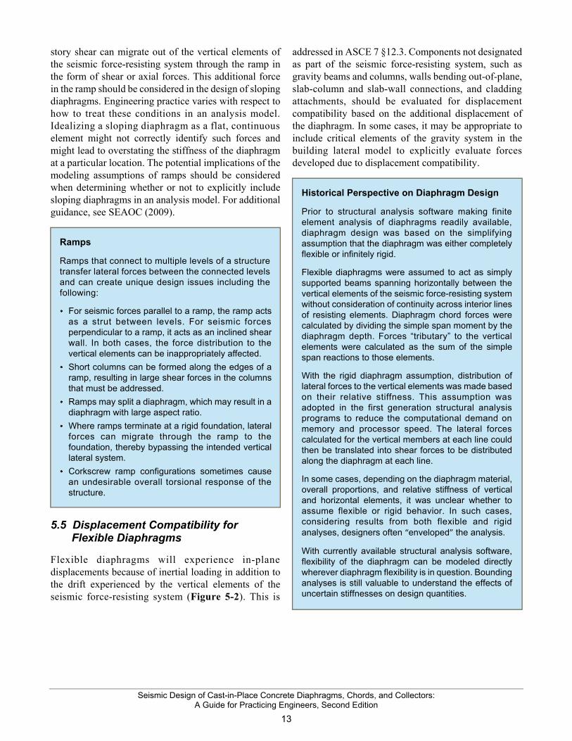
story shear can migrate out of the vertical elements of the seismic force-resisting system through the ramp in the form of shear or axial forces. This additional force in the ramp should be considered in the design of sloping diaphragms. Engineering practice varies with respect to how to treat these conditions in an analysis model. Idealizing a sloping diaphragm as a flat, continuous element might not correctly identify such forces and might lead to overstating the stiffness of the diaphragm at a particular location. The potential implications of the modeling assumptions of ramps should be considered when determining whether or not to explicitly include sloping diaphragms in an analysis model. For additional guidance, see SEAOC (2009).
5.5 Displacement Compatibility for Flexible Diaphragms
Flexible diaphragms will experience in-plane displacements because of inertial loading in addition to the drift experienced by the vertical elements of the seismic force-resisting system (Figure 5-2). This is
addressed in ASCE 7 §12.3. Components not designated as part of the seismic force-resisting system, such as gravity beams and columns, walls bending out-of-plane, slab-column and slab-wall connections, and cladding attachments, should be evaluated for displacement compatibility based on the additional displacement of the diaphragm. In some cases, it may be appropriate to include critical elements of the gravity system in the building lateral model to explicitly evaluate forces developed due to displacement compatibility.
Ramps
Ramps that connect to multiple levels of a structure transfer lateral forces between the connected levels and can create unique design issues including the following:
For seismic forces parallel to a ramp, the ramp acts as a strut between levels. For seismic forces perpendicular to a ramp, it acts as an inclined shear wall. In both cases, the force distribution to the vertical elements can be inappropriately affected.
Short columns can be formed along the edges of a ramp, resulting in large shear forces in the columns that must be addressed.
Ramps may split a diaphragm, which may result in a diaphragm with large aspect ratio.
Where ramps terminate at a rigid foundation, lateral forces can migrate through the ramp to the foundation, thereby bypassing the intended vertical lateral system.
Corkscrew ramp configurations sometimes cause an undesirable overall torsional response of the structure.
Historical Perspective on Diaphragm Design
Prior to structural analysis software making finite element analysis of diaphragms readily available, diaphragm design was based on the simplifying assumption that the diaphragm was either completely flexible or infinitely rigid.
Flexible diaphragms were assumed to act as simply supported beams spanning horizontally between the vertical elements of the seismic force-resisting system without consideration of continuity across interior lines of resisting elements. Diaphragm chord forces were calculated by dividing the simple span moment by the diaphragm depth. Forces “tributary” to the vertical elements were calculated as the sum of the simple span reactions to those elements.
With the rigid diaphragm assumption, distribution of lateral forces to the vertical elements was made based on their relative stiffness. This assumption was adopted in the first generation structural analysis programs to reduce the computational demand on memory and processor speed. The lateral forces calculated for the vertical members at each line could then be translated into shear forces to be distributed along the diaphragm at each line.
In some cases, depending on the diaphragm material, overall proportions, and relative stiffness of vertical and horizontal elements, it was unclear whether to assume flexible or rigid behavior. In such cases, considering results from both flexible and rigid analyses, designers often “enveloped” the analysis.
With currently available structural analysis software, flexibility of the diaphragm can be modeled directly wherever diaphragm flexibility is in question. Bounding analyses is still valuable to understand the effects of uncertain stiffnesses on design quantities.

Seismic Design of Cast-in-Place Concrete Diaphragms, Chords, and Collectors: A Guide for Practicing Engineers, Second Edition
14
6. Diaphragm Analysis Guidance
6.1 Diaphragm Modeling and Analysis Approaches
Internal forces in a diaphragm are calculated using approaches that range from simple idealizations to complex computer analysis. The analysis need only be as complex as necessary to represent how lateral forces flow through the building, including the diaphragms. For regular buildings in which lateral resistance is provided by similar vertical elements distributed throughout the floor plan, simple models are often adequate for determining the diaphragm forces. For buildings with irregularities or with dissimilar vertical elements, more complex models may be required to determine the diaphragm design forces. Regardless of the idealization that is selected, the analysis method is required to satisfy requirements of equilibrium, and the design is required to provide design strengths at least equal to required strengths for all elements in the load path.
ACI 318 §12.5.1.3 identifies four acceptable approaches for diaphragm modeling and analysis:
1. Beam model. A diaphragm can be modeled as a beam whose depth is equal to the full diaphragm depth, using methods such as those described in Section 6.2.
2. Strut-and-tie model. A diaphragm or diaphragm segment can be modeled as a strut-and-tie system, as described in Section 6.3.
3. Finite element model. A diaphragm can be idealized with a finite-element model, as described in Section 6.4.
4. Alternative models. A diaphragm may be designed by any alternative method, provided that it satisfies the requirements of equilibrium and provides design strengths at least equal to required strengths for all elements in the load path. Section 6.5 and Section 6.6, discuss design for large openings and design using partial-depth collectors, and provide examples of alternative models.
6.2 Beam Models
Beam models represent a diaphragm as a beam on rigid or flexible supports. Analysis involves determination of (1) internal moments, shears, and reactions and (2) the determination of resulting internal forces. These are models are discussed in Section 6.2.1 and Section 6.2.2, respectively.
6.2.1 Analysis for Moments, Shears, and Reactions
Three versions of beam models are widely used, specifically the basic equivalent beam model, the equivalent beam-on-springs model, and the corrected equivalent beam model. The models described in the following paragraphs are appropriate for levels that are not major transfer levels, such that the main role of the diaphragm is to transfer lateral inertial loads among vertical elements at a level. At a main transfer level, such as a podium where forces are transferring from one set of vertical elements to another set through the diaphragm, the beam models need to be adjusted to represent this behavior.
Basic equivalent beam model. This model treats the diaphragm as a horizontal beam spanning between idealized rigid supports, such as shown in Figure 3-1. The rigid supports represent vertical elements, such as shear walls. For the case shown, the beam is simply supported, because the walls are at the far ends of the diaphragm. This approach may also be used with the walls located inboard of the diaphragm edges, in which case the equivalent beam cantilevers beyond the supports.
Shear and moment diagrams are established by treating the diaphragm as if it were a beam. Figure 3-1b shows the shear and moment diagrams for the case with walls at the far ends of the diaphragm.
Traditional Models versus Computer Analysis
The equivalent beam, equivalent beam-on-springs, and corrected equivalent beam models (discussed in Section 6.2) are traditional, approximate approaches that are still used extensively to design concrete diaphragms. They can be especially suitable for diaphragms in regions of low and moderate seismicity because force demands typically are low relative to the inherent strength, such that more precise computation is unwarranted. In regions of high seismicity, where seismic demands commonly exceed inherent strength, computer analysis to determine diaphragm demands is increasingly common.
Seismic Design of Cast-in-Place Concrete Diaphragms, Chords, and Collectors: A Guide for Practicing Engineers, Second Edition
15
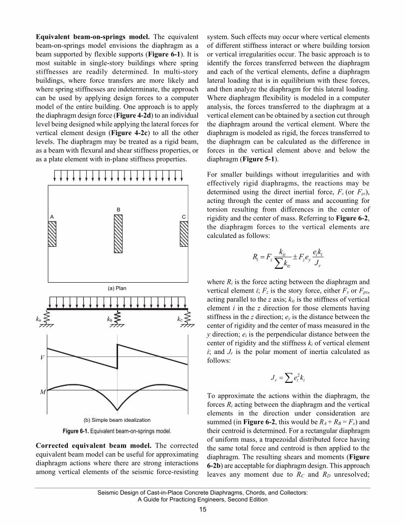
Equivalent beam-on-springs model. The equivalent beam-on-springs model envisions the diaphragm as a beam supported by flexible supports (Figure 6-1). It is most suitable in single-story buildings where spring stiffnesses are readily determined. In multi-story buildings, where force transfers are more likely and where spring stiffnesses are indeterminate, the approach can be used by applying design forces to a computer model of the entire building. One approach is to apply the diaphragm design force (Figure 4-2d) to an individual level being designed while applying the lateral forces for vertical element design (Figure 4-2c) to all the other levels. The diaphragm may be treated as a rigid beam, as a beam with flexural and shear stiffness properties, or as a plate element with in-plane stiffness properties.
(a) Plan
(b) Simple beam idealization
Figure 6-1. Equivalent beam-on-springs model.
Corrected equivalent beam model. The corrected equivalent beam model can be useful for approximating diaphragm actions where there are strong interactions among vertical elements of the seismic force-resisting
system. Such effects may occur where vertical elements of different stiffness interact or where building torsion or vertical irregularities occur. The basic approach is to identify the forces transferred between the diaphragm and each of the vertical elements, define a diaphragm lateral loading that is in equilibrium with these forces, and then analyze the diaphragm for this lateral loading. Where diaphragm flexibility is modeled in a computer analysis, the forces transferred to the diaphragm at a vertical element can be obtained by a section cut through the diaphragm around the vertical element. Where the diaphragm is modeled as rigid, the forces transferred to the diaphragm can be calculated as the difference in forces in the vertical element above and below the diaphragm (Figure 5-1).
For smaller buildings without irregularities and with effectively rigid diaphragms, the reactions may be determined using the direct inertial force, Fx (or Fpx), acting through the center of mass and accounting for torsion resulting from differences in the center of rigidity and the center of mass. Referring to Figure 6-2, the diaphragm forces to the vertical elements are calculated as follows:
iz i ii z z y
riz
k e kR F F e
Jk
where Ri is the force acting between the diaphragm and vertical element i; Fz is the story force, either Fx or Fpx, acting parallel to the z axis; kiz is the stiffness of vertical element i in the z direction for those elements having stiffness in the z direction; ey is the distance between the center of rigidity and the center of mass measured in the y direction; ei is the perpendicular distance between the center of rigidity and the stiffness ki of vertical element i; and Jr is the polar moment of inertia calculated as follows:
2r i iJ e k
To approximate the actions within the diaphragm, the forces Ri acting between the diaphragm and the vertical elements in the direction under consideration are summed (in Figure 6-2, this would be RA + RB = Fx) and their centroid is determined. For a rectangular diaphragm of uniform mass, a trapezoidal distributed force having the same total force and centroid is then applied to the diaphragm. The resulting shears and moments (Figure 6-2b) are acceptable for diaphragm design. This approach leaves any moment due to RC and RD unresolved;
A B
C
kA kB kC
V
M
Seismic Design of Cast-in-Place Concrete Diaphragms, Chords, and Collectors: A Guide for Practicing Engineers, Second Edition
16
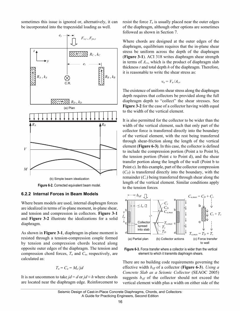
sometimes this issue is ignored or, alternatively, it can be incorporated into the trapezoidal loading as well.
(a) Plan
(b) Simple beam idealization
Figure 6-2. Corrected equivalent beam model.
6.2.2 Internal Forces in Beam Models
Where beam models are used, internal diaphragm forces are idealized in terms of in-plane moment, in-plane shear, and tension and compression in collectors. Figure 3-1 and Figure 3-2 illustrate the idealizations for a solid diaphragm.
As shown in Figure 3-1, diaphragm in-plane moment is resisted through a tension-compression couple formed by tension and compression chords located along opposite outer edges of the diaphragm. The tension and compression chord forces, Tu and Cu, respectively, are calculated as:
Tu = Cu = Mu /jd
It is not uncommon to take jd = d or jd ≈ h where chords are located near the diaphragm edge. Reinforcement to
resist the force Tu is usually placed near the outer edges of the diaphragm, although other options are sometimes followed as shown in Section 7.
Where chords are designed at the outer edges of the diaphragm, equilibrium requires that the in-plane shear stress be uniform across the depth of the diaphragm (Figure 3-1). ACI 318 writes diaphragm shear strength in terms of Acv, which is the product of diaphragm slab thickness t and total depth h of the diaphragm. Therefore, it is reasonable to write the shear stress as:
vu = Vu /Acv
The existence of uniform shear stress along the diaphragm depth requires that collectors be provided along the full diaphragm depth to “collect” the shear stresses. See Figure 3-2 for the case of a collector having width equal to the width of the vertical element.
It is also permitted for the collector to be wider than the width of the vertical element, such that only part of the collector force is transferred directly into the boundary of the vertical element, with the rest being transferred through shear-friction along the length of the vertical element (Figure 6-3). In this case, the collector is defined to include the compression portion (Point a to Point b), the tension portion (Point c to Point d), and the shear transfer portion along the length of the wall (Point b to Point c). In this example, part of the collector compression (CD) is transferred directly into the boundary, with the remainder (Cv) being transferred through shear along the length of the vertical element. Similar conditions apply to the tension forces.
(a) Partial plan (b) Collector actions (c) Force transfer
to wall
Figure 6-3. Force transfer where a collector is wider than the vertical element to which it transmits diaphragm shears.
There are no building code requirements governing the effective width beff of a collector (Figure 6-3). Using a Concrete Slab as a Seismic Collector (SEAOC 2005) suggests beff of the collector should not exceed the vertical element width plus a width on either side of the
V
M
RA RB
ey
RA , kA
RD , kD
RB , kB
RC , kC
Fx,z , Fpx,z
z
y ei
C.R.
Collector spread into slab
Tv
lw
beff
≤ lw /2 Cv CD Cu,max
TD
Tu,max
Cu,max = CD + Cv
Tu,max = TD + Tv
Cv + Tv

Seismic Design of Cast-in-Place Concrete Diaphragms, Chords, and Collectors: A Guide for Practicing Engineers, Second Edition
17
vertical element equal to half the contact length between the diaphragm and the vertical element. Eccentric collectors result in moment about the vertical element that must be considered in design.
6.3 Strut-and-Tie Models
Strut-and-tie models can be used to idealize the flow of force through a diaphragm in a way that satisfies equilibrium. Such models have not been used extensively for overall design of diaphragms, although sometimes they can be useful for this purpose. Strut-and-tie models are more often used to identify force paths and reinforcement layouts around discontinuities. Where used, this Guide recommends that distributed reinforcement of at least 0.0025 times the gross slab area be provided in each direction to control cracking.
Figure 6-4 illustrates how strut-and-tie models can be used to understand required reinforcement layouts. In this example, force from a structural wall is transferred around an opening through a collector, into a diaphragm, and into nearby basement walls. The force transfer in the diaphragm can be visualized as occurring through compression struts acting at an angle between about 30° and 60° relative to the wall force. Considering the zone bounded by Point a, Point b, Point c, and Point d as a free body diagram, moment equilibrium about Point d requires a tension tie between Point b and Point c, which must be developed into the adjacent diaphragm segment. Moment equilibrium about Point c cannot be provided by a tension tie from Point a to Point d because the tension tie would have to be anchored to the basement wall, which is typically not designed for an out of plane force generated by a tension tie. Instead, moment equilibrium about Point c is provided by a compressive force from the adjacent diaphragm segment at Point a. Force reversal as occurs during earthquakes would reverse the diagonal compression struts and require a tension tie between Point a and Point d Point a tension tie between Point e and Point h (not shown). Section 7 provides additional discussion on how to detail the required reinforcement.
Excessive openings in podium diaphragms can create challenging design conditions. Consider the idealized example in Figure 6-5. If the wall along axis B must transfer a large force through the podium diaphragm to the basement wall, the only suitable path might be through a long collector between Point a and Point b. If collector bars are cut as the collector force decreases along the length, the elongation of the collector would
be approximately the yield strain times the length between Point a and Point b. If the collector is fixed at Point b, then Point a must move an amount equal to the elongation, possibly resulting in excessive shear deformation of the panel with corners at Point c, Point d, Point f, and Point e. Alternatively, if the diaphragm deforms excessively because of a long collector, the wall shear force is likely to find an alternative load path through the shear wall down to the level below the podium slab. Another example occurs for the wall along axis D. The strut-and-tie solution satisfies statics, but the long load path involves movement of the wall that would be incompatible with the connection at Point j. Fewer openings in a podium slab would be preferred and should be sought early in the design.
Figure 6-4. Strut-and-tie model at force transfer to basement wall.
Figure 6-5. Challenging design conditions.
6.4 Finite Element Models
Finite element modeling of a diaphragm can be useful for identifying the load paths in diaphragms with large openings or other irregularities, modeling the stiffness of ramps in parking garages, and assessing the force transfers among vertical elements of the seismic force-resisting system. Figure 6-6 shows an example of an irregularly-shaped diaphragm that may warrant use of
Collector Compression strut Tension tie
Develop tension tie beyond node Basement wall
Basement Wall force
Wall force
Opening
Basement wall
Wall
Wall
Plan

Seismic Design of Cast-in-Place Concrete Diaphragms, Chords, and Collectors: A Guide for Practicing Engineers, Second Edition
18
finite element modeling. Figure 4-4 illustrates a building with vertical irregularities, because of setbacks and podium transfers, that likely warrants modeling diaphragm flexibility for levels adjacent to the irregularities.
To adequately model the diaphragm flexibility, finite element meshing typically needs to be 1/5 to 1/3 of the bay length or wall length, although a finer mesh sometimes is beneficial. If section cuts are made through the diaphragm model to determine the shear distribution within the diaphragm, the finite element mesh at and near the section cut should be moderately fine.
Figure 6-6. Irregularly shaped diaphragm.
In subterranean levels, diaphragm forces can migrate from the diaphragm into the basement walls, as may occur, for example, where the basement walls act as the flanges for diaphragm in-plane moment resistance. In such cases, section cuts need to extend through the basement walls such that the basement wall forces are not missed in the structural system design.
6.5 Diaphragms with Large Openings
Design of a diaphragm with a large opening is analogous to design of a beam with an opening. Consider the opening shown in Figure 6-7. One approach is to assume that the reinforcement labeled L collects the uniform diaphragm shear that acts to the left of the opening and drags it to the portions of the diaphragm above and below the opening in proportion with their relative stiffnesses. The reinforcement labeled R then collects the shear from above and below the opening and drags it to the portion of the diaphragm to the right of the opening. The reinforcement labeled T and B resists the local moment within the section above and below the opening. This moment is sometimes approximated as
VT (l/2) and VB (l/2), which is correct if the inflection point is at the center of the length of the opening. The inflection point may vary, which will increase the moment. If a finite element analysis is being used, section cuts can be used to determine the forces, and a hand analysis approach such as the one described here can be used as a tool to check the results.
Figure 6-7. Diaphragms with large openings.
6.6 Partial-Depth Collectors
An alternative design procedure is to determine the minimum length of the vertical element plus collector required for transferring shear to the vertical element, and then provide a collector, if required, along this length. For example, in Figure 6-8, the required length considering diaphragm shear strength is lac, and the corresponding partial-depth collector extends along that length. Where the upper limit on diaphragm shear strength is used, this approach minimizes both the collector area and length. In some cases, all of the force might theoretically be transferred directly to the vertical element without a collector, but we recommend extending a collector at least a bay width or 25 feet (7.6 m) into the diaphragm, whichever is longer, to control cracking near the ends of the wall. The design force in the collector should vary linearly from zero at the end of the collector to a maximum at the face of the vertical element.
Design of partial-depth collectors requires additional considerations. A load path must be established for inertial forces in all areas of the diaphragm to reach the concentrated area of higher shear adjacent to the vertical elements and partial-depth collectors. In this regard, the load path is similar to a dapped or notched beam for which a concentration of reinforcement is required at the edge of the full-depth section that collects the shear and transfers it to the reduced depth section at the end of the beam. For the diaphragm, the load path requires a
Collector
Wall
Compression chord
Wall
Tension chord
T
L
B
R
l
VT
VB

Seismic Design of Cast-in-Place Concrete Diaphragms, Chords, and Collectors: A Guide for Practicing Engineers, Second Edition
19
secondary distributed collector adjacent to the partial-depth collector. Typical, distributed slab reinforcement parallel to the vertical element serves as this secondary collector. Where necessary, the area of distributed slab reinforcement is increased locally to deliver shear forces from the lower shear section to the higher shear region. The secondary collector also picks up local inertial forces from the area with corners at Point c, Point d, Point g, and Point f and from the small area to the left of it.
Figure 6-8. Partial-depth collector.
For the partial-depth collector shown in Figure 6-8, the following design considerations apply. Near the diaphragm midspan, the full depth of the diaphragm is used to resist diaphragm moment and shear. Thus, at midspan the required chord tension force is Tu = Mu,hi /jd, where jd refers to diaphragm depth between Point h and Point i. Along the line from Point e to Point g, the full-depth diaphragm must be sufficient to transfer a uniform shear stress of v = Vu,eg /Acv. The secondary collector reinforcement must be sufficient to transmit in tension the shear acting along the line from Point f to Point g plus additional diaphragm inertial forces in the region with corners at Point c, Point d, Point g, and Point f. Along the line from Point a to Point c, the diaphragm reinforcement must be sufficient to transfer Vu,ac as uniformly distributed shear. Partial-depth collector reinforcement along the line from Point b to Point c must be sufficient to carry the shear picked up along the line from Point b to Point c. And finally, chord reinforcement along the line from Point c to Point f must be capable of resisting the diaphragm moments along that length assuming the effective depth of the diaphragm is reduced to the length of the line between Point e and Point f. If the secondary distributed collector was not
included in the design, the effective depth of the diaphragm for all moment calculations would be reduced to the length of the line between Point e and Point f, requiring larger area of chord reinforcement placed entirely along the line from Point c to Point j, and distributed steel would still be required in the region with corners at Point c, Point d, Point g, and Point f to transmit inertial loads developed in that region to the shallower effective beam of depth from Point e to Point f. Treating the diaphragm as a shallower beam of depth from Point e to Point f also could result in large cracks forming at the extreme tension edge of the diaphragm as it is flexed under lateral load. See Sabelli et al. (2009a; 2009b) for additional discussion of partial-depth collectors.
6.7 Diaphragm Shear Distribution
A design should ensure that the shear stress distribution in a diaphragm is in equilibrium with the internal moment resistance. For example, where in-plane moment is resisted by chords located at the outer boundaries of the diaphragm, concepts of shear flow require that the shear stress distribution be constant through the diaphragm depth (Figure 3-1). A partial-depth collector design, as illustrated in Figure 6-8, resists nonuniform shear stress through a combination of secondary collectors and chords that provides a complete load path. A design that resists moment through reinforcement that is uniformly distributed through the diaphragm depth would resist diaphragm shear that is zero at the outer tension face and increases linearly to a maximum value of approximately 2Vu /Acv near the compression side.
6.8 Diaphragm-to-Vertical-Element Force Transfer
Diaphragm shear is transferred to vertical elements by the collectors and by shear-friction between the diaphragm and the vertical element. Where collector bars enter a vertical element, such as a wall, the force is transferred directly to the wall. However, the collector may need to extend into the vertical element a distance that is much longer than a collector bar development length. Figure 6-9 illustrates the case where a tension collector enters one side of a wall.
The shear Vx+1 in the wall segment above the diaphragm is normally considered to produce uniform shear flow vx+1 across the wall width. The shear Vx in the wall segment below the diaphragm is increased by the force Tu transferred from the collector. To achieve uniform
lac
V
M
Vu,ad Vu,eg
Mu,hi
Partial-depth collector
Secondary distributed collector
Chord reinforcement
Seismic Design of Cast-in-Place Concrete Diaphragms, Chords, and Collectors: A Guide for Practicing Engineers, Second Edition
20
shear flow vx across the lower wall segment, at least some of the collector steel must extend along the full wall length. Alternatively, the collector reinforcement can be lap-spliced with added wall reinforcement that drags the force toward the far side of the wall. In the case where a compression collector frames into the left side of the wall, with a tension collector on the right side, the tension collector reinforcement need not extend full length, as only a portion of the force that transfers to the wall is provided by the tension collector. Collectors that extend through the entire length of a vertical element ensure that force is transferred from the collector to the element without further consideration.
Figure 6-9. Transfer of collector force directly to shear wall.
6.9 Diaphragm Slabs on Ground
Although slabs bearing on ground develop inertial forces, conventional practice is to assume that these forces are resisted by the ground and can be otherwise ignored. For some structures, however, slabs bearing on ground are used as diaphragms to tie together and distribute forces among connected vertical elements and foundation elements. This is done where the foundation supporting a vertical element does not have adequate soil friction and passive bearing strength to resist design horizontal load on its own. The slab on ground diaphragm redistributes some of the horizontal load to locations where additional resistance to sliding is obtained. Friction below the slab-on-ground diaphragm and below other foundation elements, as well as the passive bearing acting on these other foundation elements, provide the added resistance to sliding.
Slabs on ground that serve as diaphragms are considered structural slabs. Structural slabs are required to be designed in accordance with ACI 318. Although these slabs typically do not need to be reinforced for flexure caused by loads on the surface of the slab, they must be reinforced for the in-plane shear and moment. These slabs must also meet the minimum reinforcement requirements for a structural slab.
Vx + 1
V = vx + 1 + Tu
vx + 1
Vx > vx + 1
Tu
Wall above
Collector
Wall below
Collector reinforcement
Note: Extension into wall at least ld

Seismic Design of Cast-in-Place Concrete Diaphragms, Chords, and Collectors: A Guide for Practicing Engineers, Second Edition
21
7. Design Guidance
7.1 Load and Strength Reduction Factors
Chapter 2 of ASCE 7 defines the load combinations applicable to diaphragm and collector design. The load combinations require consideration of horizontal seismic effects, vertical seismic effects, dead load, live load, and other loads such as soil pressures, snow, fluid, and other applicable loads. ASCE 7 §12.4.2 defines the horizontal seismic effect as Eh = ρQE and the vertical seismic effect as Ev = 0.2SDSD. In these expressions, ρ is the redundancy factor, QE is the effect of horizontal seismic forces, SDS is the design spectral response acceleration parameter at short periods, and D is the effect of dead load. In general, Eh and Ev must be applied in all combinations in both positive and negative directions.
The basic seismic load combinations are:
1.2 0.2
0.9 –v h
v h
D E E L S
D E E
(ASCE 7-10 §2.3.6)
Where the overstrength factor is required to be used, the seismic load combinations are:
1.2 0.2
0.9 –v mh
v mh
D E E L S
D E E
(ASCE 7-10 §2.3.6)
In these expressions, Emh = ΩoQE, that is, the effect of horizontal seismic forces including overstrength factor Ωo. The load factor on L is permitted to equal 0.5 for all occupancies in which unreduced design live load is less than or equal to 100 psf (4.79 kN/m2), with the exception of garages or areas occupied as places of public assembly.
In general, diaphragms and collectors are permitted to be designed for seismic forces applied independently in
each of the two orthogonal directions. For structures assigned to Seismic Design Category C, D, E, or F and having nonparallel systems (plan irregularity Type 5 per ASCE 7-16 Table 12.3-1), however, diaphragm design must consider the interaction of orthogonal loading in one of two ways. If the Equivalent Lateral Force Procedure or Modal Response Spectrum Analysis is used, 100 percent of the effects in one primary direction are to be combined with 30 percent of the effects in the other direction. If a response-history analysis is performed in accordance with ASCE 7 §16.1 or ASCE 7 §16.2, orthogonal pairs of ground motion histories are to be applied simultaneously.
Although not required by ASCE 7, common practice is to consider the orthogonal combination for all diaphragm and collector design. This Guide adopts that approach.
Where beam models are used, design for moment or moment combined with axial force can be done using a tension-compression couple, with strength reduction factor ϕ = 0.9.
For diaphragm shear, the basic strength reduction factor is ϕ = 0.75. However, for structures that resist the earthquake effects using intermediate precast structural walls in Seismic Design Category D, E, or F, or special moment frames or special structural walls in any Seismic Design Category, the strength reduction factor for diaphragm shear is ϕ = 0.6 if the nominal diaphragm shear strength is less than the shear corresponding to the diaphragm moment strength. In addition, the strength reduction factor for diaphragm shear may not exceed the minimum strength reduction factor for shear used for the vertical components of the seismic force-resisting system. Consequently, for most designs, the strength reduction factor for diaphragm shear is ϕ = 0.6.
For tension members, such as collectors in tension, ϕ = 0.9.
Strength Design Method
ACI 318 uses the strength design method to provide the intended level of safety. The basic requirement for strength design can be expressed as design strength ≥ required strength. The design strength is written in the general form ϕSn, in which ϕ is a strength reduction factor and Sn is the nominal strength. The required strength is expressed in terms of factored loads, or related internal moments and forces. The strength design method is essentially the same as the Load and Resistance Factor Method (LRFD) used for the design of some other materials.
Governing Load Combinations
The load combinations specified in IBC §1605 are based on the load combinations from ASCE 7 Chapter 2. However, the IBC factors on snow load are different from those in ASCE 7. Where there is a discrepancy between the two documents and the IBC is the governing code, the IBC load combinations take precedence.
Seismic Design of Cast-in-Place Concrete Diaphragms, Chords, and Collectors: A Guide for Practicing Engineers, Second Edition
22
For compression members, such as collectors or struts around openings in compression, ϕ = 0.65, except ϕ = 0.75 in the unusual case that the compression member is designed as a spiral reinforced column.
7.2 Tension and Compression Chords
Where simple beam models are used, ACI 318 §12.5.2.3 requires that nonprestressed reinforcement resisting tension due to moment be located within h/4 of the tension edge of the diaphragm, where h = diaphragm depth measured in the plane of the diaphragm at that location. Where the diaphragm depth changes along the length of the diaphragm span, it is permitted to develop reinforcement into adjacent diaphragm segments that are not within the h/4 limit. Figure 7-1 illustrates these requirements. See additional discussion in Section 7.5.2. There are no restrictions on placement of prestressed reinforcement provided to resist moment through precompression.
Figure 7-1. Locations of nonprestressed reinforcement resisting tension due to moment and axial force.
Section 6.2.2 described the calculation of chord forces when simplified beam models are used to approximate the diaphragm internal forces. Where nonprestressed reinforcement is concentrated near the edge of the diaphragm, the equation for the reinforcement area of the tension chord, using ϕ = 0.9, is:
us
y
TA
f
Typically, the chord reinforcement is placed within the middle third of the slab or beam thickness, so as to minimize interference with slab or beam longitudinal
reinforcement and to reduce contributions to slab and beam flexural strength.
Where chord reinforcement is positioned within a beam, the chord and the beam typically are oriented to resist orthogonal effects, such that the same reinforcing bars can resist moment for loading in one direction and chord tension for loading in the orthogonal direction. Where orthogonal effects are combined using the 100%–30% combination rule per ASCE 7 §12.5.3(a), such that the longitudinal reinforcement is the larger of that required to resist (a) 1.0X + 0.3Y and (b) 0.3X + 1.0Y. In most cases, if the beam is part of a special moment frame, the required longitudinal reinforcement will be sufficient for chord requirements.
Bonded tendons may be used as reinforcement to resist collector forces, diaphragm shear, or diaphragm flexural tension, but they must be proportioned such that the stress due to design earthquake forces does not exceed 60,000 psi (420 MPa). Unbonded, unstressed tendons are not permitted to resist collector, shear, or moment forces because of concerns about the development of wide cracks and excessive flexibility under earthquake loading. Precompression forces from unbonded tendons, however, is permitted to resist diaphragm forces, provided there is a complete seismic load path.
The use of precompression warrants added discussion. In a typical prestressed floor slab, prestressing is proportioned to resist the load combination of 1.2D + 1.6Lred. For earthquake design, the gravity load to be resisted by prestressing is reduced because the governing load combination is equal to 1.2D + f1Lred + E. Therefore, the percentage of prestressing, originally provided for gravity load resistance, that is available as precompression to resist in-plane loads is:
1 1.61 1.2 / 1.2 100
/ /red red
f
D L D L
For example, if D = 120 psf (5.7 kN/m2), Lred = 24 psf (1.1 kN/m2) assuming L = 40 psf (1.9 kN/m2) and is reducible by 40 percent, f1 = 0.5 for a floor live load and the minimum permitted prestress of 125 psi (0.86 MPa), the precompression stress fpc available to resist earthquake effects is 14.5 psi (0.10 MPa). Higher precompression stress is available where higher prestressing is used. The preceding example assumes that only the prestressing provided for gravity load resistance is being used for diaphragm in-plane moment
h2 h1
l2 l1
h2/4
h2/4
h1/4
h1/4 Vertical element
Plan
Diaphragm boundary
Zones for placement of chord reinforcement
Lateral load
Reinforcement for span l1, placed within depth h1/4
Reinforcement can be developed outside shaded zones. Other reinforcement required for force transfer not shown.
Seismic Design of Cast-in-Place Concrete Diaphragms, Chords, and Collectors: A Guide for Practicing Engineers, Second Edition
23
resistance. Of course, additional prestressing can be provided for the express purpose of resisting diaphragm moment. The diaphragm in-plane moment that can be resisted by precompression is obtained using diaphragm gross-section properties within the equation M = fpcSm. Additional moment, if any, must be resisted by bonded reinforcement.
The flexural compression zone usually does not require direct consideration in design and detailing. The exception is where the flexural compression force Cu due to diaphragm in-plane moment is resisted by a strut placed along an opening or other discontinuity (Figure 7-2).
Figure 7-2. Confinement reinforcement in axial struts around openings.
If the calculated compressive stress on a strut exceeds 0.2f c’, or 0.5f c’ where design forces have been amplified to account for overstrength of the vertical elements of the seismic force-resisting system, confinement reinforcement is required (ACI 318 §18.12.3.2). The required confinement reinforcement, including hoops with required seismic hook dimensions, can be difficult to fit within typical slab depths and may require increased slab depth. Where required, confinement reinforcement should be continued into the slab beyond the strut at least the longer of the tension development length of the longitudinal reinforcement or 12 inches
(300 mm). The same requirements also apply where diaphragm shear is carried through struts.
7.3 Diaphragm Shear
Every section of a diaphragm is to be designed to have unit design shear strength not less than the factored unit shear. For diaphragms having chord reinforcement located near the extreme flexural tension edge, the factored shear Vu is uniformly distributed. The design shear strength in this case is given by ϕVn, where ϕ = 0.6 or 0.75 as discussed in Section 7.1, and Vn is given by:
2
0.17
, psi
, MPan
'n cv c t y
'cv c t y
V A
V
f f
A f f
(ACI 318 §18.12.9.1)
in which uniformly distributed slab reinforcement providing ρt is perpendicular to the diaphragm moment reinforcement (that is, parallel to the shear force) (Figure 7-3). Where the factored shear stress varies throughout the diaphragm depth, the design unit shear strength, calculated by substituting the unit area for Acv in the above equation, must exceed the factored unit shear at every section. In addition, the maximum value of Vn cannot exceed:
8 , psi
0.67 , MPa
'c cv
'c cv
f A
f A (ACI 318 §18.12.9.1)
ACI 318 requires shear reinforcement ρt to be provided only in the direction parallel to the applied shear. However, most typical diaphragms are relatively deep members, similar to squat walls, for which shear strength is derived from distributed reinforcement in both directions. Therefore, this Guide recommends that distributed reinforcement provided for shear be at least equal to ρt in both directions.
According to ACI 318, reinforcement provided to resist diaphragm in-plane forces shall be in addition to reinforcement designed to resist other load effects, except reinforcement designed to resist shrinkage and temperature effects shall be permitted to also resist diaphragm in-plane forces. As discussed in Section 7.2, load combinations including earthquake effect E, have lower factors on the gravity load effects. Any excess reinforcement that is not required for gravity loads under the seismic load combination can be used to resist in-plane forces.
Wall Diaphragm
Diaphragm opening
Section A-A
Fx or Fpx

Seismic Design of Cast-in-Place Concrete Diaphragms, Chords, and Collectors: A Guide for Practicing Engineers, Second Edition
24
(a) Shear and collector (b) Collector
reinforcement actions
Figure 7-3. Shear reinforcement, collector reinforcement, and shear-friction reinforcement.
Shear reinforcement can be placed anywhere within the slab thickness within the required cover limits. Some structural engineers specify a continuous mat of bottom reinforcement that satisfies both the diaphragm shear and slab moment requirements. Where this is done, the total reinforcement area is the sum of areas required for moment and shear, considering the governing load combination.
7.4 Force Transfer between Diaphragm and Vertical Elements
Force transfer between a diaphragm and the vertical elements generally occurs through a combination of collectors (including their connections) and shear-friction. Seismic design forces for collectors and their connections are determined by the design seismic forces and the selected load path. See Section 5 for guidance on design seismic forces, including proper application of Ωo and ρ factors. See Section 6 for guidance on load paths. Figure 7-3 illustrates a typical collector and its connections.
Minimum cross-sectional dimensions of collectors can be determined by tension or compression limits. For the case of compression, the factored compressive force must not exceed the design compressive strength of the collector element, defined by:
= 0.85 'o c g s y sP f A A f A
Because collectors act in tension for earthquake loading in one direction and compression for loading in the other direction, loading in compression seldom controls. For structures assigned to Seismic Design Category D, E, or F, ACI 318 §18.12.7.5 requires that collector elements
have transverse confinement reinforcement if the compressive stress based on the gross cross section exceeds 0.2f c’ for standard load combinations and 0.5f c’ for load combinations with overstrength. The transverse confinement reinforcement is required until the compressive stresses are below 0.15f c’ and 0.4f c’ for standard load combinations and load combinations with overstrength, respectively. Collector cross-sectional dimensions (for example, the width and thickness of the shaded region in Figure 7-3) sometimes are sized to avoid triggering these requirements for transverse confinement reinforcement.
For the case of tension, the collector must be sized so that longitudinal reinforcement at splices and anchorage zones has either (a) or (b), as follows:
(a) Center-to-center bar spacing of at least three longitudinal bar diameters, but not less than 1½ inches (38 mm), and concrete clear cover of at least two and one-half longitudinal bar diameters, but not less than 2 inches (50 mm); or
(b) Transverse reinforcement providing Av at least the greater of:
0.75 and 50 , psi
0.062 and 0.35 , MPa
' w wc
yt yt
' w wc
yt yt
b s b sf
f f
b s b sf
f f
This is intended to reduce the possibility of bar buckling and provide adequate bar development conditions in the vicinity of splices and anchorage zones. See ACI 318 §18.12.7.6 and ACI 318 §11.4.6.3.
The transfer of forces between the diaphragm, collector, and vertical element of the seismic force-resisting system depends on the layout of various elements. Consider the
The Confinement Trigger for Collectors
According to ACI 318, collectors must be confined wherever the nominal compressive stress exceeds 0.2fc ′ (or 0.5fc ′). The 0.2fc ′ trigger was adopted from a similar provision that traditionally was used for shear walls. The trigger was based on the idea that if the wall was designed for an effective R = 5, yielding in compression would be indicated if the compressive stress under design-level loads reached (1/5)fc ′. The shift to 0.5fc ′ assumes Ωo = 2.5.
Collector
Collector reinforcement
Shear friction reinforcement
Shear reinforcement
vu
beff
lab
lbc
lcd
Cu,max
Tu,max

Seismic Design of Cast-in-Place Concrete Diaphragms, Chords, and Collectors: A Guide for Practicing Engineers, Second Edition
25
example illustrated in Figure 7-3. The maximum design compressive force in collector segment ab is Cu,max = Ωovutlab and the maximum design tensile force in collector segment cd is Tu,max = Ωovutlcd. The collector is 50 percent wider than the width of the wall it frames into; therefore, two-thirds of the collector force is transferred directly into the wall boundary, with one-third being transferred through shear-friction adjacent to the long face of the wall. Shear-friction reinforcement is required along the entire length of the collector and wall. Along lab and lcd, continuous bottom reinforcement in the diaphragm, if present, may suffice to resist the total shear forces vutlab and vutlcd, respectively. Along length lbc, the total design shear force is vutlbc + (Tu,max + Cu,max)/3 = vut(lbc + Ωo(lab + lcd)/3), and this force may well require more than the typical bottom mat reinforcement to achieve required strength. The apparent inconsistency in applying Ωo to some forces and not to others, leading to section cuts that are not in equilibrium, is a recognized inconsistency, but is required by the building code.
The construction sequence determines some of the details for shear-friction design. Where a vertical element is cast to the bottom of a diaphragm, followed by casting the diaphragm and then another vertical element, cold joints exist both above and below the diaphragm (Figure 7-4a). In this case, shear-friction requirements must be satisfied through monolithic concrete at the face of the wall using dowels and through the two cold joints using a combination of wall reinforcement and dowels. Where a vertical element is formed ahead of casting the diaphragm, a cold joint exists at the face of the wall (Figure 7-4b). In this latter case, design of the dowels to resist shear through shear-friction across the cold joint becomes critical. ACI 318 §18.12.10.1 requires that all construction joints be clean, free of laitance, and also intentionally roughened to a full amplitude of approximately ¼ inch (6 mm). Alternatively, some engineers specify shear keys.
When designing shear-friction reinforcement, out-of-plane (due to gravity loads) and in-plane (due to seismic loads) effects must be combined using the appropriate load combination. Connections between diaphragms and vertical elements of the seismic force-resisting system also must be capable of resisting forces associated with out-of-plane loading of the vertical elements. Where the Equivalent Lateral Force Procedure or Modal Response Spectrum Analysis are used, orthogonal effects are combined using the 100%–30% rule, such that only 30 percent of the out-of-plane seismic force needs to be
considered concurrent with the diaphragm shear-friction transfer.
(a) Diaphragm sandwiched between vertical wall segments
(b) Diaphragm connection to slip-formed wall
Figure 7-4. Shear reinforcement, collector reinforcement, and shear-friction reinforcement.
7.5 Special Cases
7.5.1 Openings Adjacent to Vertical Elements
Architectural requirements sometimes dictate openings adjacent to walls that are part of the seismic force-resisting system. This can create force transfer challenges, especially at podium levels where large forces may need to be transferred. The preferred approach is to work with the architect to plan locations of openings so that they do not interfere with major force transfers. Where openings in critical locations cannot be avoided, workable solutions can sometimes be designed.
Figure 6-4 illustrates the force transfer from a shear wall to a basement wall where the two walls are separated by a large opening in the diaphragm. Figure 7-5 illustrates how reinforcement might be detailed in the diaphragm segment to the left of the opening.
For the collector in tension, uniform shear flow can be assumed between the collector and diaphragm segment along the line from Point a to Point b, resulting in shear stresses acting on the diaphragm segment as shown in Figure 7-5b. Moment equilibrium of the segment requires equal shear stresses along the face from Point a to Point b, the face from Point b to Point c, the face from
Diaphragm
Diaphragm
Dowels
Dowels Cold joint
Cold joint
Cold joint
Structural wall
Structural wall
Collector reinforcement distributed transversely into the diaphragm
Collector reinforcement distributed transversely into the diaphragm

Seismic Design of Cast-in-Place Concrete Diaphragms, Chords, and Collectors: A Guide for Practicing Engineers, Second Edition
26
Point a to Point d, and the face from Point c to Point d. Shear reinforcement satisfying ACI 318 Eq. 18.12.9.1 is required uniformly in both directions to resist this applied shear. The basement wall also must be reinforced locally along the line from Point c to Point d for the shear applied along that length. The edge from Point b to Point c of the diaphragm segment requires a tension tie to pick up the shear stresses along that edge; that tension tie needs to be developed into the adjacent diaphragm. A compression reaction near Point a completes the equilibrium requirements. Similar but opposite action occurs for the collector in compression (Figure 7-5c).
(a) Plan
(b) Tension transfer (c) Compression transfer
Figure 7-5. Reinforcement to transfer collector force around an opening.
7.5.2 Re-Entrant Corners
At re-entrant corners of diaphragms, such as shown in Figure 7-6, either tension chord from Point a to Point d can extend across the full width of the diaphragm, or the chord can be provided in segments that extend along the edge of the diaphragm as shown. A strut-and-tie model can be used to define design forces in the zone bounded by Point b, Point c, and Point e. As shown, the horizontal component of the chord force at Point c can be transferred through a diagonal compression strut to Point e. The chord bars at Point c need to be extended a development length beyond the node at Point c. Both North-South (NS) and East-West (EW) reinforcement are required to extend from the node at Point e, with overlapping hooks to provide development of the forces at the node. Finally, the design of tension chord between
Point e and Point f can be based on the corresponding moment and effective depth.
The NS component of the diagonal compression strut at Point c can be resisted by compression in the adjacent diaphragm. Nonetheless, a NS steel ratio not less than 0.0025 should be provided in this region, as recommended by this Guide wherever strut-and-tie models are used.
Figure 7-6. Reinforcement associated with re-entrant corners.
7.5.3 Steps and Depressions
Where steps or depressions occur, reinforcement must be provided to transfer the design forces through the offset. Figure 7-7 illustrates collector reinforcement passing through a step and depression. Figure 7-7b shows flexural cracking of the depression that could be induced by the eccentric loading.
To the extent practicable, collector reinforcement should be placed to minimize the eccentricity on opposite sides of the step when in tension. If the collector also transmits compression, the eccentricity is determined by the gross dimensions of the offset. If collector reinforcement cannot be placed straight, either it can be bent or bent bars can be spliced with the main bars. The vertical force created by offset bars should be resisted by hoop legs. See analogous provisions for offset column bars in ACI 318 §10.7.6.4. In addition, any eccentricity in the collector bars creates a moment Tue that must be resolved within the structure. If there is a wall at this location oriented perpendicular to the collector, the wall may be able to resist the moment by out-of-plane bending.
Tie
Reinforcement Collector
Opening
Basement wall below
Develop in tension
Develop in tension
Wall Diaphragm
≥ ld
Plan
Bars “fe” hooked and lapped with bars “eb”

Seismic Design of Cast-in-Place Concrete Diaphragms, Chords, and Collectors: A Guide for Practicing Engineers, Second Edition
27
(a) Step
(b) Depression
Figure 7-7. Collector reinforcement passing through a step and depression.
Alternatively, the overlapped section of the step can be reinforced as a beam to transmit moment through torsion to adjacent columns, although this can be problematic because of challenging reinforcement details and because of large twist that may be associated with torsion. If the diaphragm is transmitting shear across the step, hoop reinforcement can resist the applied shear through shear-friction at the interface. “Sawtooth” diaphragms, in which the entire diaphragm is stepped, create obvious problems if chords or collectors have to pass across the step.
7.5.4 Extension of Collectors into Diaphragms
Collectors can extend the full depth of a diaphragm or partial depth, depending on the assumed load path. See Section 6 for more information on diaphragm analysis. Where forces are transferred from a vertical element into a transfer level, the length of the collector is sometimes selected based on the length required to transfer its force
into the diaphragm. In most cases, the required collector length is equal to the total transfer force divided by the shear strength per unit length of the diaphragm. By this approach, tension in a collector decreases linearly along its length. Common practice is to stagger bar cutoffs along the length, maintaining design strength not less than the tension force at any section. As discussed in Section 6.3, long collectors can be problematic.
7.5.5 Reinforcement Development
ACI 318 requires that all reinforcement used to resist collector forces, diaphragm shear, or flexural tension be developed or spliced for fy in tension. Reductions in development or splice length for calculated stresses less than fy are not permitted. Mechanical splices, if used to transfer forces between the diaphragm and vertical elements of the seismic force-resisting system, must be Type 2 per ACI 318 §18.2.7.1.
Tu Tu
lsp lsp
lsp lsp
e e
Mu = Tue
Tu Tu
lsp
lsp
e
Mu = Tue

Seismic Design of Cast-in-Place Concrete Diaphragms, Chords, and Collectors: A Guide for Practicing Engineers, Second Edition
28
8. Additional Requirements
8.1 Materials Properties
ACI 318 §19.2 requires minimum specified compressive strength f c’, of 2,500 psi (17 MPa) for structural concrete including diaphragms, although f c’ at least 3,000 psi (21 MPa) is recommended here. Where diaphragms are cast monolithically with portions of special moment frames or shear walls for a structure assigned to Seismic Design Category D, E, or F, the minimum f c’ is 3,000 psi (21 MPa) (ACI 318 §19.2) for that part of the diaphragm. This is typically not an issue because f c’ of 4,000 to 6,000 psi (28 to 41 MPa) is commonly specified for floor systems.
For some structures, specified concrete strength of moment frame columns or shear walls is higher than that of the diaphragm/floor system. ACI 318 §15.3, which allows column concrete compressive strength to be 1.4 times that of the floor system, is intended to apply only for axial load transmission and therefore should not be applied to walls or columns of the seismic force-resisting system. Many walls or moment frame columns are located along edges of the building slab or along openings, where the concrete is not confined by adjacent concrete on all sides. Additionally, these elements have high shear stress that must be transferred through the floor, requiring the higher strength.
For shear walls, the higher wall strength can be maintained using a jump core or flying form system for the wall construction to precede the floor construction. Where concrete for the portion of the wall or moment frame through the thickness of the floor system is placed with concrete for the floor system, the higher strength concrete should be puddled at these elements and extended 2 feet (0.6 m) into the slab as allowed for columns in ACI 318 §15.3.1 and also described in commentary section R15.3.
Where lightweight concrete is used, the provisions of ACI 318 §19.2 apply if the diaphragm concrete is also part of a special moment frame or special shear wall.
According to ACI 318 §20.2.2.4 the values of fy and fyt used in design of reinforcement resisting shear shall not exceed 60,000 psi (420 MPa), except the value shall not exceed 80,000 psi (550 MPa) for welded deformed wire reinforcement. The intent of the code requirement is to limit the width of shear cracks.
Reinforcement for chords and collectors is limited by the general requirements for bonded reinforcement of ACI 318 Chapter 20, with two exceptions.
(a) Where chord or collector reinforcement is placed within beams, including the effective flange of special moment frames, and therefore acts as the beam flexural reinforcement, the chord or collector reinforcement must comply with ASTM A706, Standard Specification for Deformed and Plain Low-Alloy Steel Bars for Concrete Reinforcement (ASTM 2016), or equivalent.
(b) ACI 318 §12.5.1.5 limits the stress from design earthquake forces to 60,000 psi (420 MPa) for bonded tendons. Although the stress in other collector and chord reinforcement is not limited, consideration should be given to deformation compatibility between tension chords, collectors, and the floor slab. High tensile stress and strains in collectors and chords can result in excessive cracking that will migrate into the slab. This, in turn, can negatively affect shear strength. Therefore, this Guide recommends limiting the usable design stress to 80,000 psi (550 MPa) for reinforcement.
8.2 Special Inspection
Reinforced concrete diaphragms and their chords and collectors are a part of the seismic force-resisting system. Proper construction of diaphragms and their elements is paramount to ensuring that the structure will perform as intended during a major earthquake.
The IBC requires that the design professional for a building prepare a statement of special inspections identifying the required inspections for construction of the building. This Guide recommends that inspection of diaphragms include collector reinforcement placement and spacing, surface roughness at diaphragm-to-wall connections, reinforcement placement and spacing at diaphragm-to-wall connections, and splices.
The special inspector is required to inspect work for conformance to the approved design drawings and specifications. Per IBC §1704, the engineer of record should designate the specific inspections and tests to be performed in a Statement of Special Inspections, submitted as part of the permit application. Contract documents should specify that the special inspector will furnish inspection reports to the building official, the

Seismic Design of Cast-in-Place Concrete Diaphragms, Chords, and Collectors: A Guide for Practicing Engineers, Second Edition
29
engineer of record, owner, and contractor. Discrepancies should be brought to the immediate attention of the contractor for correction, then, if uncorrected, to the proper design authority and the building official. A final signed report is to be submitted stating whether the work requiring special inspection was, to the best of the inspector’s knowledge, completed in conformance with the approved plans and specifications and the applicable workmanship provisions of the IBC and its referenced standards.
8.3 Bracing Columns to Diaphragms
Diaphragms brace columns where they connect. See fourth bullet of Section 2. The force required to brace a column is not defined in ACI 318, but a force of 2 percent to 4 percent of the column axial load is generally considered sufficient. For low and midrise cast-in-place concrete buildings, this check is rarely made as the inherent strength of diaphragm-to-column connections easily provides this strength. For tall buildings with large heavily loaded columns, this check should be made. For these columns, the diaphragm check should include bearing stresses at the face of the column, adequacy of diaphragm reinforcement anchored into the column at edge conditions, and adequate diaphragm buckling strength to resist the bracing force. These requirements and recommendations also apply to precast buildings with cast-in-place diaphragms.
Inclined columns require a more rigorous check of forces at the diaphragm-to-column interface. At the top and bottom of the inclined portion of a column, there is a horizontal component of force imparted on the diaphragm that the diaphragm must resist and deliver to vertical elements of the seismic force-resisting system (Figure 2-1). The magnitude of this horizontal component depends on the inclination of the column. Where architecturally feasible, the column inclination from vertical should not exceed about 15° (one to four, horizontal to vertical). Larger inclination angles are not generally prohibited by the building code, but large diaphragm thrusts and challenges in adequately reinforcing the column, diaphragm, and diaphragm- column connection should be anticipated. Where the column axial loads are low and the inclination approaches vertical, the slab may be capable of resisting the horizontal component. The slab may also be adequate at intermediate levels where the inclined column passes without a change in direction. At these intermediate levels, only the incremental vertical force added to the column at that level creates a horizontal thrust for which
the connection must be designed. For highly loaded inclined columns and columns with inclines from vertical greater than 15°, it may be necessary to thicken the slab or provide a beam to transfer the thrust from the inclined column.
8.4 Interaction of Diaphragm Reinforcement with Vertical Elements
Chord and collector reinforcement of diaphragms is often located in beams that are part of special moment frames or within slabs adjacent to those beams. This reinforcement will likely not be stressed to its yield strength from chord or collector forces during the earthquake at the same time the moment frame beam is fully yielding. However, deformation compatibility will typically dictate that chord or collector reinforcement will yield along with the beam (the reinforcement will strain as the beam flexes). Therefore, this chord or collector reinforcement will add flexural strength to the beam. This added flexural strength must be considered as part of the beam strength when proportioning the beam and column to meet the strong-column-weak-beam requirements of ACI 318 §18.7.3. If the chord or collector reinforcement is within the beam, the added flexural strength must also be included when determining the probable flexural strength used to compute the design shear force for the beam as required by ACI 318 §18.6.4 and when determining requirements for beam-column joint strength. (A strict interpretation of the ACI 318 provisions is that this reinforcement need not be included in beam and beam-column joint shear calculations if it is located in the beam effective flange width rather than within the beam web; however, the preferred approach is to include it in all cases where it is located within the effective beam width.) Similar considerations should be made when designing coupling beams for shear walls in accordance with ACI 318 §18.10.7.1.
Collector or chord compressive forces can also increase the flexural strength of beams as the axial force is likely below the balance point. In determining the compressive force of a chord to add to a beam, only 30 percent of the chord force is likely required as the chord force is usually caused by earthquake forces orthogonal to forces loading the moment frame. Collector forces that act on beams are likely caused by the same earthquake force that loads the moment frame. Therefore, 100 percent of the collector force is likely required to be considered when designing the beam. Similar considerations apply to chord and collector tension forces. These axial forces should be considered when evaluating strong-column-

Seismic Design of Cast-in-Place Concrete Diaphragms, Chords, and Collectors: A Guide for Practicing Engineers, Second Edition
30
weak-beam requirements and when determining the beam design shear force and design shear strength. Similar considerations also apply to the design of intermediate moment frames.
Collectors and chords are designed to respond linearly under axial tension and compression, but where these elements enter the boundaries of shear walls, they may be subjected to significant flexure as the walls rock back
and forth during an earthquake. Where possible, the reinforcement of these elements should be located to minimize flexural yielding. This may be achieved by using shallower members or by placing the main collector or chord reinforcing bars near the mid-depth. Transverse confining reinforcement is recommended for structures assigned to Seismic Design Category D, E, or F, at these locations in order to improve compressive capacity of the concrete and buckling resistance of the reinforcement.

Seismic Design of Cast-in-Place Concrete Diaphragms, Chords, and Collectors: A Guide for Practicing Engineers, Second Edition
31
9. Detailing and Constructability Issues
9.1 Diaphragm Reinforcement
Many concrete slabs are designed to have a continuous bottom mat of uniformly distributed reinforcement. For this reason, transverse reinforcement provided for diaphragm shear resistance is commonly incorporated into the bottom mat. In heavily reinforced diaphragms that are thick slabs, a continuous top and bottom mat of reinforcement is often provided. Designers should specify the required lap splice and development length of the reinforcement in the construction documents, as diaphragm reinforcement splice and development requirements may exceed what is otherwise required for slabs supporting gravity loads only.
In post-tensioned slabs, the location of diaphragm reinforcement needs to be coordinated with the locations of post-tensioned strands and associated anchorages. Designating layers within the slab depth for the diaphragm reinforcement and the post-tensioned strands is an effective method of minimizing conflict. The design of the slab needs to take into account the actual location of the layers of reinforcement if this approach is used.
Welded wire fabric is not generally used for diaphragm reinforcement in cast-in-place slabs because the reinforcement provided for the gravity loading uses standard reinforcing bars. The use of welded wire fabric for diaphragm reinforcement is typically limited to topping slabs over precast concrete systems or over steel metal decks.
9.2 Collector and Chord Detailing
Collector and chord reinforcement is often located in the mid-depth of the slab. In structures assigned to Seismic Design Category D, E, or F, ACI 318 requires that center-to-center spacing at least 3db, but not less than 1.5 inches (38 mm), and concrete clear cover at least 2.5db, but not less than 2 inches (50 mm). Otherwise, transverse reinforcement is required.
Connections of collector reinforcement to vertical elements of the seismic force-resisting system are often congested regions. In many cases, numerous large diameter bars are required to be developed into confined boundary zones of shear walls as shown in Figure 9-1a. Designers should study these connections in detail to ensure adequate space exists. In many cases, increased
slab thickness or beams are required to accommodate reinforcement detailing at the connections. Figure 9-1b shows where a beam was created to accommodate the collector reinforcement, but congestion still may impede both placement of concrete and ultimate performance. Designers should also consider the slab depth provided where large collectors intersect. Multiple layers of large diameter reinforcing bars can result in excessive congestion. Similarly, designers should be aware of locations where collectors intersect concrete beam longitudinal reinforcement.
(a) Collector connection to shear wall boundary zone
(b) Beam for large collector
Figure 9-1. Collector detailing.
Long collectors, such as the one shown in Figure 9-2, can accumulate strains over their length, resulting in displacements that may be incompatible with modeling assumptions or deformation capacities of adjacent

Seismic Design of Cast-in-Place Concrete Diaphragms, Chords, and Collectors: A Guide for Practicing Engineers, Second Edition
32
components. Designers can consider additional collector reinforcement to reduce the strain and the associated collector elongation. In addition, providing confinement reinforcement can also increase the ductility of the concrete locally, but will not address potential problems associated with any incompatible deformations. Redesigning the force transfer system should also be considered.
Where collector (or chord) reinforcement is required at a location coincident with a beam, the chord reinforcement can be placed within the beam. Beam transverse reinforcement, if properly detailed, can also serve as collector (or chord) confinement. If chord reinforcement does not fit entirely within the beam width, then the effective diaphragm depth should be based on the actual distribution and location of the chord reinforcement.
Figure 9-2. A long collector with confinement reinforcement.
9.3 Confinement
Transverse (confinement) reinforcement may be required in collectors or other elements transferring axial forces around openings or other discontinuities. The required seismic hook dimensions can sometimes make reinforcement detailing difficult in typical slab depths. If there are concerns over congestion, designers can increase the width of the collector within the slab or the thickness of the slab until the compressive stresses are low enough that confinement is not required. Alternatively, beams with sufficient dimensions can be added to facilitate the required confinement detailing. Where confinement is not required by the code, the designer still may consider adding some transverse reinforcement to improve connection toughness at critical
locations. Figure 9-2 and Figure 9-3 show examples of added transverse reinforcement that is not in the form of closed hoops yet will result in improved collector behavior.
Figure 9-3. Confinement of a collector.
9.4 Shear Transfer
Shear transfer between diaphragms and vertical elements of the seismic force-resisting system can be accomplished in a number of ways. Shear-friction reinforcement can be provided for transfer of forces along the length of the vertical element. For cases where the vertical elements of the seismic force-resisting system are cast in advance of the slabs, or vice versa, the use of shear keys should be considered to achieve a coefficient of friction, µ, of 1.0. There is no standard practice for shear keys. As an example, shear keys for an 8-inch (200-mm)-thick slab might be ¾ inches (20 mm) deep × 3½ inches (90 mm) tall × 8 inches (200 mm) wide spaced 12 inches (300 mm) on center, centered within the slab thickness.
Shear-friction reinforcement must be developed at each critical failure plane, and the designer should consider the location of the construction joint when selecting μ during design.
Compressive collector forces can be transferred via direct bearing at wall ends. An appropriate effective slab bearing area should be considered, and compressive stresses in the slab should be evaluated to determine whether confinement is required.
Tensile forces can be transferred through collector reinforcement that is developed in both the diaphragm and the vertical element. The length of tension collectors within the diaphragm should consider the assumed shear

Seismic Design of Cast-in-Place Concrete Diaphragms, Chords, and Collectors: A Guide for Practicing Engineers, Second Edition
33
stress distribution as well as the shear strength of the diaphragm. The length within the vertical element must be sufficient to fully transfer the force to the vertical element. See Section 6.8 for more information on diaphragm-to-vertical-element force transfer.
9.5 Mechanical Splices
Large diameter diaphragm and collector reinforcing bars are commonly spliced using mechanical couplers. Because lap splices of No. 14 bars or larger are prohibited by ACI 318, mechanical couplers are required. For smaller diameter bars, mechanical splices may be implemented as a means to reduce reinforcement congestion within a slab. Mechanical splices used to transfer forces between the diaphragm and the vertical elements of the seismic force-resisting system are required to be Type 2 per ACI 318 §18.2.7.1. Mechanical couplers considered for a project should have current ICC approval. Detailing and placement must provide the required cover over the coupler body, which has a diameter larger than the diameter of the bars being coupled.
Many contractors choose to cast vertical elements of the seismic force-resisting system in advance of the slabs. Mechanical splice and anchorage devices facilitate these construction methods. Approved form-face couplers are commonly used for anchorage of shear-friction and collector reinforcement. Designers should pay attention to the size of the couplers because they are typically large relative to the bar being anchored. Figure 9-4 shows shear-friction reinforcement connections to a shear wall with approved form-face couplers.
Figure 9-4. Form-face couplers for dowel anchorage.
9.6 Conduits and Embedded Services
The placement of electrical conduit, plumbing sleeves, and other services within a reinforced concrete slab is common practice. Figure 9-5 shows an example of embedded conduit within a reinforced cast-in-place concrete diaphragm. This example appears extreme, but similar conditions are often encountered.
Figure 9-5. Embedded conduit.
Designers should consider these and similar items that can reduce the strength and stiffness of the diaphragm. Typical details showing restrictions on the placement of conduits and embedded services and associated supplemental reinforcement are helpful but often are insufficient to cover many of the conditions that occur in a project. The specifications or General Notes should identify specific mandatory restrictions; for example, for post-tensioned construction, it could be mandatory that conduit or other embedded items not displace the vertical profile of the tendons. Contract Documents should require the contractor to provide detailed layout drawings of the conduits and other embedded services well in advance of concrete placement. This allows the designer time to review the impact to the diaphragm and to provide supplemental instructions, including additional reinforcement, as required. Pre-construction meetings can provide an opportunity for the designer to review embedment placement and reinforcement requirements in detail prior to construction.
The location of nonstructural items embedded into the slab should also be considered with respect to collector layout. In many instances, conflicts between structural and nonstructural items can be problematic. Figure 9-6 shows a conflict in the location of a nonstructural component embedment with the alignment of the collector reinforcement.

Seismic Design of Cast-in-Place Concrete Diaphragms, Chords, and Collectors: A Guide for Practicing Engineers, Second Edition
34
Figure 9-6. Conflict between the location of collector reinforcing with a nonstructural component.
9.7 Location of Construction Joints
Construction joints create weakened planes within a diaphragm. They can also impact development and splices of reinforcement. Shear-friction reinforcement can be provided across construction joints, if necessary, to maintain continuity of the diaphragm in shear. The impacts to the continuity and development of chord and collector reinforcement at construction joints should also be understood. As with conduits, typical details, limitations, and instructions should be clearly detailed in the Contract Documents, which should also require that contractors provide detailed construction joint layout drawings well in advance of concrete placement.

Seismic Design of Cast-in-Place Concrete Diaphragms, Chords, and Collectors: A Guide for Practicing Engineers, Second Edition
35
10. References
ACI (2011). Building code requirements for structural concrete (ACI 318-11) and commentary on building code requirements for structural concrete (ACI 318R14), American Concrete Institute, Farmington Hills, MI.
ACI (2014). Building code requirements for structural concrete, (ACI 318-14), and commentary on building code requirements for structural concrete (ACI 318R14), American Concrete Institute, Farmington Hills, MI.
ASCE (2010). Minimum design loads for buildings and other structures, ASCE/SEI 7-10, American Society of Civil Engineers, Reston, VA.
ASCE (2016). Minimum design loads and associated criteria for buildings and other structures, ASCE/SEI 7-16, American Society of Civil Engineers, Reston, VA.
ASTM (2016). Standard specification for deformed and plain low-alloy steel bars for concrete reinforcement, ASTM A706 / A706M-16, ASTM International, West Conshohocken, PA.
Chopra, A.K. (2005). Earthquake dynamics of structures: A primer, Second Edition, Earthquake Engineering Research Institute, Oakland, CA.
Corley, W.G., Cluff, L., Hilmy, S., Holmes, W., and Wight, J. (1996). Concrete parking structures, Earthquake Spectra, Vol. 12, No. S1, pp. 75-98.
Deierlein, G., Reinhorn, A.M., and Willford, M. (2010). Nonlinear structural analysis for seismic design, NIST GCR 10-917-5, NEHRP Seismic Design Technical Brief No. 4, National Institute of Standards and Technology, Gaithersburg, MD.
Fleischman, R.B., Farrow, K.T., and Eastman, K. (2002). Seismic performance of perimeter lateral system structures with highly flexible diaphragms, Earthquake Spectra, Vol. 18, No. 2, pp. 251-286.
ICC (2015). International Building Code, International Code Council, Washington, DC.
LATBSDC (2014). An alternative procedure for seismic analysis and design of tall buildings located in the Los Angeles region, Los Angeles Tall Buildings Structural Design Council.
Nakaki, S.D. (2000). Design guidelines for precast and cast-in-place concrete diaphragms, EERI professional fellowship report, Earthquake Engineering Research Institute, Oakland, CA.
PEER (2010). Guidelines for performance-based seismic design of tall buildings, PEER Report 2010/05, prepared by the TBI guidelines working group, Pacific Earthquake Engineering Research Center, University of California, Berkeley, Berkeley, CA.
Rodriguez, M.E., Restrepo, J.I., and Blandón, J.J. (2007). Seismic design forces for rigid floor diaphragms in precast concrete building structures, Journal of Structural Engineering, Vol. 133, No. 11, pp. 1604-1615.
Sabelli, R., Pottebaum, W., and Dean, B. (2009a). Diaphragms for seismic loading, Part 1, Structural Engineer, January, pp. 24-29.
Sabelli, R., Pottebaum, W., and Dean, B. (2009b). Diaphragms for seismic loading, Part 2, Structural Engineer, February, pp. 22-23.
SEAOC (2005). Using a concrete slab as a seismic collector, Seismology and Structural Standards Committee, Structural Engineers Association of California, April, Sacramento, CA.
SEAOC (2009). Concrete parking structures, The SEAOC blue book: Seismic design recommendations, Structural Engineers Association of California, Sacramento, CA.
SEAOC (2010). Seismic design of concrete parking structure ramps, Seismology Committee, Structural Engineers Association of California, STRUCTURE, July, pp. 8-10.
Shakal, A.F., Huang, M.J., Darragh, R.B., Brady, A.G., Trifunac, M.D., Lindvall, C.E., Wald, D.J., Heaton, T.H., and Mori, J.J. (1995). Recorded ground and structure motions, Earthquake Spectra, Vol. 11, No. S2, pp. 13-96.

Seismic Design of Cast-in-Place Concrete Diaphragms, Chords, and Collectors: A Guide for Practicing Engineers, Second Edition
36
11. Notations and Abbreviations
Notations
Acv gross area of concrete section bounded by diaphragm slab thickness t and total depth h measured in the direction of shear force considered
Ag gross area of concrete section
As area of nonprestressed longitudinal tension reinforcement
Av area of transverse reinforcement for shear
beff effective width of collector
bw web width
CD factored collector compressive force transferred directly to edge of vertical element
Cu factored compressive force at section
Cu,max maximum value of Cu
Cv factored collector compression force transferred through shear-friction to vertical element
Cvx vertical distribution factor for design seismic forces
d distance from extreme compression fiber to centroid of longitudinal tension reinforcement
D effect of dead load
db nominal diameter of bar
e eccentricity created by diaphragm step or depression
E effect of earthquake forces
Eh effect of horizontal earthquake forces
ei perpendicular distance between the stiffness ki of vertical element i relative to center of rigidity
Emh effect of horizontal earthquake forces including overstrength factor Ωo
Ev vertical earthquake effect
ey eccentricity of diaphragm design lateral force relative to center of rigidity
f c′ specified compressive strength of concrete
fpc precompression stress available to resist earthquake effects
fy specified yield strength of reinforcement
fyt specified yield strength fy of transverse reinforcement
f1 live load factor, taken as 0.5 except taken as 1.0 for garages, areas occupied as places of public assembly, and all areas where L is greater than 100 psf.
Fpx diaphragm design force
Fpx,max upper limit to the diaphragm design force
Fpx,min lower limit to the diaphragm design force
Fx portion of the seismic base shear, V, induced at level x
Fz diaphragm force in z direction
hx height above the base to level x
Ie importance factor
j coefficient defining the internal moment arm in a member resisting moment
Jr polar moment of inertia of stiffness of wall vertical elements
k distribution exponent for design seismic forces
ki stiffness of vertical element i
kiz stiffness of vertical element i in the z direction
l span of diaphragm or diaphragm segment
ld development length in tension
lsp required lap splice length in tension
lw length of wall, or other vertical element, in contact with diaphragm

Seismic Design of Cast-in-Place Concrete Diaphragms, Chords, and Collectors: A Guide for Practicing Engineers, Second Edition
37
L effect of live load
Lred effect of live load reduced based on tributary area
M moment at section
Mu factored moment at section
n designation for the level that is uppermost in the main portion of the building
Po nominal axial strength at zero eccentricity
QE effect of horizontal seismic (earthquake-induced) forces
R response modification coefficient
Ri reaction force in diaphragm at vertical element i
RM effective ductility factor for the system
Rs diaphragm design force reduction factor
s center-to-center spacing of reinforcement
S effect of snow load
Sa spectral response pseudo-acceleration, g
Sm elastic section modulus
Sn nominal strength
SD1 design, 5 percent damped, spectral response acceleration parameter at 1-second period
SDS design, 5 percent damped, spectral response acceleration parameter at short periods
t thickness of diaphragm slab
T fundamental period of the building
TD factored collector tension force transferred directly to edge of vertical element
TL long-period transition period
Tu factored tensile force at section
Tu,max maximum value of Tu
Tv factored collector tension force transferred through shear-friction to vertical element
vu factored shear stress or shear force per unit length
V shear force on section; also total design lateral force or shear at the base
Vn nominal shear strength
Vu factored shear force at section
Vx shear at level x
wpx weight tributary to the diaphragm at level x
wx portion of effective seismic weight of the building that is located at, or assigned to, level x
x level under consideration
X one of two orthogonal directions in which seismic forces are applied, the other direction being Y
Y one of two orthogonal directions in which seismic forces are applied, the other direction being X
δmax maximum lateral displacement of diaphragm
δwall lateral displacement of wall
λ modification factor to reflect the reduced mechanical properties of lightweight concrete relative to normal weight concrete of the same compressive strength
µ coefficient of friction
strength reduction factor
ρ redundancy factor based on the extent of structural redundancy present in a building
ρt ratio of area of distributed transverse reinforcement to gross concrete area perpendicular to that reinforcement
Ωo overstrength factor

Seismic Design of Cast-in-Place Concrete Diaphragms, Chords, and Collectors: A Guide for Practicing Engineers, Second Edition
38
Abbreviations
ACI American Concrete Institute
ASCE American Society of Civil Engineers
ASTM ASTM International
ATC Applied Technology Council
CUREE Consortium of Universities for Research in Earthquake Engineering
IBC International Building Code
ICC International Code Council
SEAOC Structural Engineers Association of California
SEI Structural Engineering Institute

Seismic Design of Cast-in-Place Concrete Diaphragms, Chords, and Collectors: A Guide for Practicing Engineers, Second Edition
39
12. Credits
Cover photo Image courtesy of Farzad Naeim.
Figure 5-2 Image courtesy of Jack Moehle, Seismic design of reinforced concrete buildings, © 2014 McGraw-Hill Education.
Figure 6-3 Image courtesy of Dominic Kelly.
Figure 6-6 Image courtesy of Stephen Harris, Simpson Gumpertz & Heger, Inc.
Figure 6-7 Image courtesy of Dominic Kelly.
Figure 9-1(a) Image courtesy of Magnusson Klemencic Associates.
Figure 9-2 Image courtesy of Stephen Harris, Simpson Gumpertz & Heger, Inc.
Figure 9-3 Image courtesy of Stephen Harris, Simpson Gumpertz & Heger, Inc.
Figure 9-4 Image courtesy of Magnusson Klemencic Associates.
Figure 9-5 Image courtesy of Magnusson Klemencic Associates.
Figure 9-6 Image courtesy of Magnusson Klemencic Associates.
Images not credited here were provided by the authors.