SEISMIC ANALYSIS AND DESIGN OF COMPOSITE STRUCTURES …
29
SEISMIC ANALYSIS AND DESIGN OF COMPOSITE STRUCTURES WITH CONCRETE-FILLED STEEL TUBES K.A. Skalomenos 1 , G.D. Hatzigeorgiou 2 D.E. Beskos 3 1. Kyoto University, Japan 2. Hellenic Open University, Greece 3. Tongji University, China THEME LECTURE by Professor Dimitri Beskos @ 16ECEE, June 18-21, Thessaloniki, Greece
Transcript of SEISMIC ANALYSIS AND DESIGN OF COMPOSITE STRUCTURES …
SEISMIC ANALYSIS AND DESIGN OF COMPOSITE
STRUCTURES WITH CONCRETE-FILLED STEEL TUBES
K.A. Skalomenos1, G.D. Hatzigeorgiou2
D.E. Beskos3
1. Kyoto University, Japan
2. Hellenic Open University, Greece
3. Tongji University, China
THEME LECTURE by Professor Dimitri Beskos
@ 16ECEE, June 18-21, Thessaloniki, Greece
INTRODUCTION
• Composite building structures in steel and concrete under seismic
loading offer significant advantages over structures either in steel
or concrete separately.
• Structural steel has high strength and ductility, results in lighter
structures with lower foundation demands and reduces erection
time. Reinforced concrete provides high rigidity and compressive
strength and is fire resistant, durable and economical.
• Composite members combining steel and concrete enjoy the
advantages of both materials. One can mention here composite
slabs, composite columns and innovative composite structural
systems (e.g. BRB systems).
For general reviews on composite structures one can mention those of Deierlein (2000), Shanmugem and Lakshmi (2001), Leon et al. (2008) and Zhao et al. (2010).
INTRODUCTION
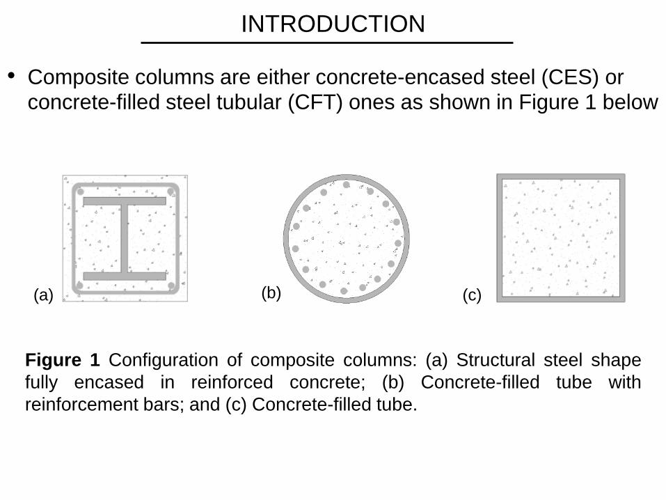
• Composite columns are either concrete-encased steel (CES) or
concrete-filled steel tubular (CFT) ones as shown in Figure 1 below
Figure 1 Configuration of composite columns: (a) Structural steel shape
fully encased in reinforced concrete; (b) Concrete-filled tube with
reinforcement bars; and (c) Concrete-filled tube.
(a) (b) (c)

INTRODUCTION
• In CES columns, one or more steel members of standard profiles
are encased in concrete. Concrete restrains local and overall
buckling of steel members and fire-proofs them. However,
formwork and additional transverse and longitudinal reinforcement
are required.
• In CFT columns, the steel tube replaces the formwork, improves
stiffness, strength and ductility, and provides confinement for
concrete with less or no reinforcement, while concrete restrains
local buckling of tube and fireproofs it acting as a heat sink.
• The present work, provides an overview on seismic analysis and
design of CFT columns and frames composed of those columns
with emphasis on recent work of the authors.
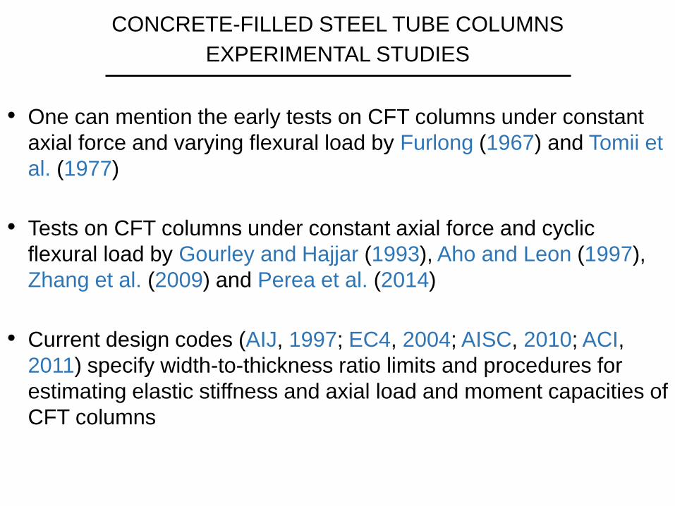
• One can mention the early tests on CFT columns under constant
axial force and varying flexural load by Furlong (1967) and Tomii et
al. (1977)
• Tests on CFT columns under constant axial force and cyclic
flexural load by Gourley and Hajjar (1993), Aho and Leon (1997),
Zhang et al. (2009) and Perea et al. (2014)
• Current design codes (AIJ, 1997; EC4, 2004; AISC, 2010; ACI,
2011) specify width-to-thickness ratio limits and procedures for
estimating elastic stiffness and axial load and moment capacities of
CFT columns
CONCRETE-FILLED STEEL TUBE COLUMNS
EXPERIMENTAL STUDIES
CONCRETE-FILLED STEEL TUBE COLUMNS
EXPERIMENTAL STUDIES
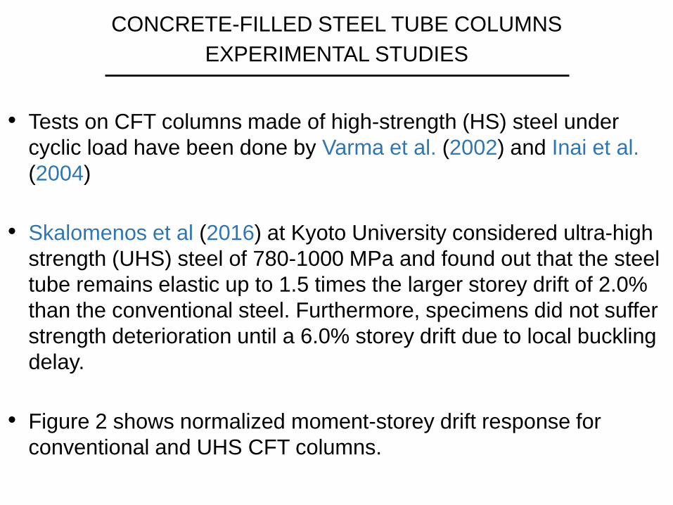
• Tests on CFT columns made of high-strength (HS) steel under
cyclic load have been done by Varma et al. (2002) and Inai et al.
(2004)
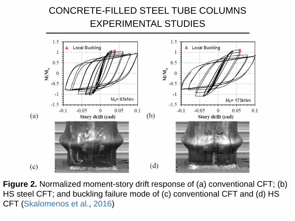
• Skalomenos et al (2016) at Kyoto University considered ultra-high
strength (UHS) steel of 780-1000 MPa and found out that the steel
tube remains elastic up to 1.5 times the larger storey drift of 2.0%
than the conventional steel. Furthermore, specimens did not suffer
strength deterioration until a 6.0% storey drift due to local buckling
delay.
• Figure 2 shows normalized moment-storey drift response for
conventional and UHS CFT columns.
CONCRETE-FILLED STEEL TUBE COLUMNS
EXPERIMENTAL STUDIES
Figure 2. Normalized moment-story drift response of (a) conventional CFT; (b)
HS steel CFT; and buckling failure mode of (c) conventional CFT and (d) HS
CFT (Skalomenos et al., 2016)
CONCRETE-FILLED STEEL TUBE COLUMNS
NUMERICAL SIMULATION
1) Distributed plasticity models
They are based on beam theory in conjunction with distributed
plasticity theory (fiber or layered models). Here we mention those
of Hajjar and Gourley (1997), Hajjar et al. (1998) and Varma et al.
(2002). The models are cyclic and account for material and
geometric nonlinearities including steel-concrete interface slip,
concrete strength and stiffness degradation, concrete confinement
and steel local buckling. These models are highly accurate but of
high computational cost. Thus, they can be practically used only for
columns or simple frames but not for complex frames or extensive
parametric studies.
CONCRETE-FILLED STEEL TUBE COLUMNS
NUMERICAL SIMULATION
2) Simplified models
• Han et al (2003) and Inai et al (2004) have developed simplified
models on the basis of their tests. However, these models
cannot simulate deterioration.
• Skalomenos et al (2013, 2014) and Serras et al (2016) for
square and circular CFTs, respectively, have developed
simplified models of concentrated plasticity type, which can take
into account all the aspects of the distributed plasticity models at
a lower computational cost. Thus, they can be easily used for
estimating the seismic behavior of composite frames accurately
and efficiently. They are described in some detail in the slides
that follow.

CONCRETE-FILLED STEEL TUBE COLUMNS
NUMERICAL SIMULATION
Simplified CFT models of Skalomenos et al (2013, 2014)
These models have been constructed as follows:
i. A very detailed and accurate 3-D finite element model based
on the advanced software ATENA was developed to simulate
the behavior of CFT columns under constant axial load and
cyclic flexural load. The finite element modeling takes into
account hysteretic concrete and steel behavior with
degradation, concrete-steel interface slip and local buckling of
steel tube as well as concrete confinement. This model is
calibrated by experimental results.

CONCRETE-FILLED STEEL TUBE COLUMNS
NUMERICAL SIMULATION
Simplified CFT models of Skalomenos et al (2013, 2014)
ii. The above 3-D finite element model is used to conduct
extensive parametric studies for the creation of a response
databank in terms of various geometrical, load and material
parameters. From this databank explicit empirical expressions
are derived through regression analysis that provide all the
required parameters of 3 well known hysteretic models (Bouc-
Wen, Ramberg-Osgood, Al-Bermani). Using these calibrated
hysteretic models comparisons with additional numerical and
experimental results are made for further adjustments.
iii. The above 3 enhanced hysteretic models are used to simulate
the inelastic behavior of concentrated plasticity models using
simple plastic hinges.

CONCRETE-FILLED STEEL TUBE COLUMNS
NUMERICAL SIMULATION
Figure 3 Proposed hysteretic models against experimental data: (a) square;
(b) square; (c) circular; and (d) circular
CONCRETE-FILLED STEEL TUBE COLUMNS
IN MOMENT RESISTING FRAMES
EXPERIMENTAL STUDIES
• Kawaquchi et al (2000): 10 reduced-scale 1-storey, 1-bay CFT-
MRFs (strong beams – weak columns) under vertical load and
alternately repeated horizontal load.
• Chen et al (2004): pseudodynamic test of full-scale 3-storey, 3-
bay CFT-MRF (with braces in middle bay)
• Herrera et al (2008): pseudodynamic test of ½ scale,4-storey
with basemement, 2-bay CFT-MRF (weak beams – strong
columns) under gravity and seismic loading
• Tsai et al (2008): pseudodynamic test of full scale, 3-story,
3-bay CFT-MRF under gravity and seismic loading
CONCRETE-FILLED STEEL TUBE COLUMNS
IN MOMENT RESISTING FRAMES
NUMERICAL STUDIES
• Herrera et al (2008) developed a CFT column model to
determine the seismic response of their CFT-MRF test in the
framework of the DRAIN-2DX software. For CFT columns they
adopted the hinge-fiber element model with local buckling of
Varma et al (2002). Panel zones/connections and beams were
simulated with spring and zero-length fiber-based elements,
respectively.
• Tort and Hajjar (2010) used their mixed finite-element
formulation for 3-D nonlinear dynamic analysis of CFT columns
to determine the cyclic response of a 1-story, 1-bay portal frame
with rectangular CFT columns and steel girder tested by
Kawaguchi (2000). The typical characteristics of the CFT
members were captured by the model.
CONCRETE-FILLED STEEL TUBE COLUMNS
IN MOMENT RESISTING FRAMES
NUMERICAL STUDIES
• Skalomenos et al (2014) used their simplified CFT column
model in the framework of the RUAUMOKO software to
determine the seismic response of the Herrera et al (2008)
CFT-MRF. The Ramberg-Osgood hinge model was used for
steel beams in conjunction with Ruaumoko’s degradation model
and the proposed by Lignos and Krawinkler (2011) relations.
Connections were modeled by two elastic-perfectly plastic
springs with elastic constants Kv and Kθ from EC3 (2005). The
scissors model with a rotational spring was used for the panel
zone.
Figure 5 of next page presents comparisons between numerical
and experimental results. The agreement is shown to be
satisfactory.
CONCRETE-FILLED STEEL TUBE COLUMNS
IN MOMENT RESISTING FRAMES
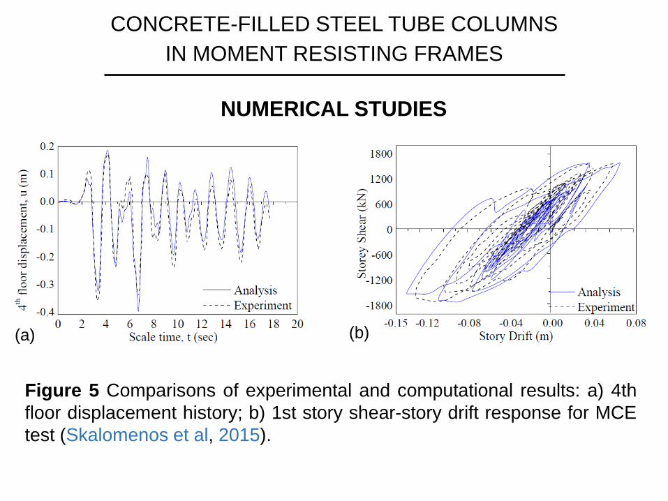
Figure 5 Comparisons of experimental and computational results: a) 4th
floor displacement history; b) 1st story shear-story drift response for MCE
test (Skalomenos et al, 2015).
(a) (b)
NUMERICAL STUDIES
SEISMIC DESIGN OF CFT-MRFs
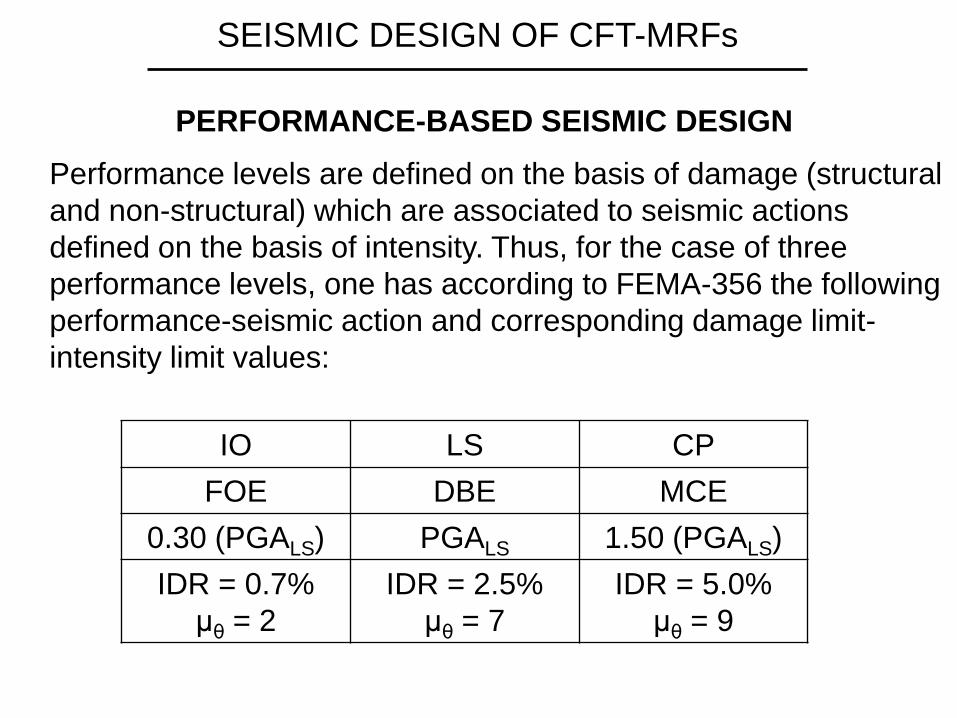
PERFORMANCE-BASED SEISMIC DESIGN
Performance levels are defined on the basis of damage (structural
and non-structural) which are associated to seismic actions
defined on the basis of intensity. Thus, for the case of three
performance levels, one has according to FEMA-356 the following
performance-seismic action and corresponding damage limit-
intensity limit values:
IO LS CP
FOE DBE MCE
0.30 (PGALS) PGALS 1.50 (PGALS)
IDR = 0.7%
μθ = 2
IDR = 2.5%
μθ = 7
IDR = 5.0%
μθ = 9
SEISMIC DESIGN OF CFT-MRFs
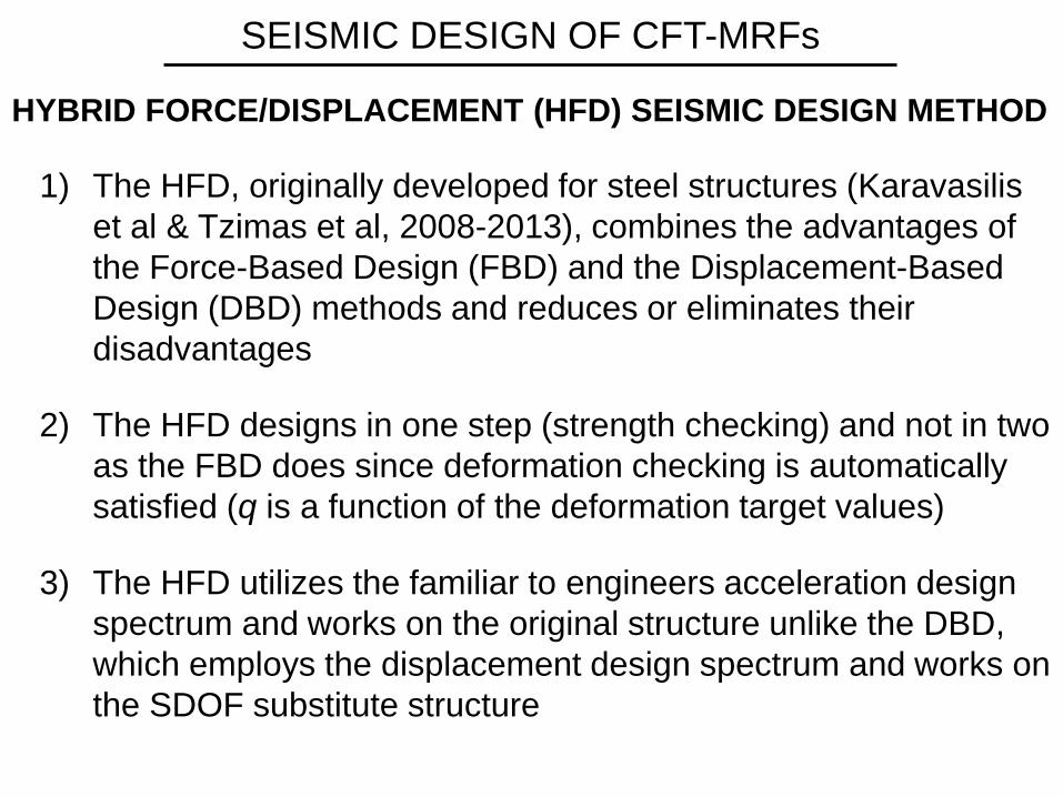
HYBRID FORCE/DISPLACEMENT (HFD) SEISMIC DESIGN METHOD
1) The HFD, originally developed for steel structures (Karavasilis
et al & Tzimas et al, 2008-2013), combines the advantages of
the Force-Based Design (FBD) and the Displacement-Based
Design (DBD) methods and reduces or eliminates their
disadvantages
2) The HFD designs in one step (strength checking) and not in two
as the FBD does since deformation checking is automatically
satisfied (q is a function of the deformation target values)
3) The HFD utilizes the familiar to engineers acceleration design
spectrum and works on the original structure unlike the DBD,
which employs the displacement design spectrum and works on
the SDOF substitute structure
SEISMIC DESIGN OF CFT-MRFs
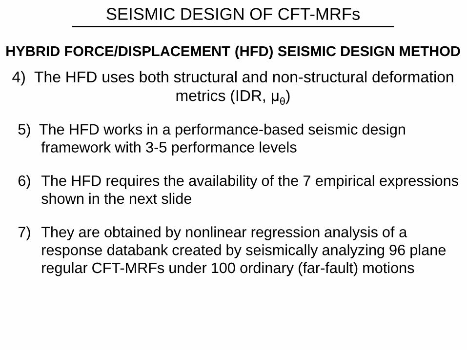
HYBRID FORCE/DISPLACEMENT (HFD) SEISMIC DESIGN METHOD
4) The HFD uses both structural and non-structural deformation
metrics (IDR, μθ)
5) The HFD works in a performance-based seismic design
framework with 3-5 performance levels
6) The HFD requires the availability of the 7 empirical expressions
shown in the next slide
7) They are obtained by nonlinear regression analysis of a
response databank created by seismically analyzing 96 plane
regular CFT-MRFs under 100 ordinary (far-fault) motions
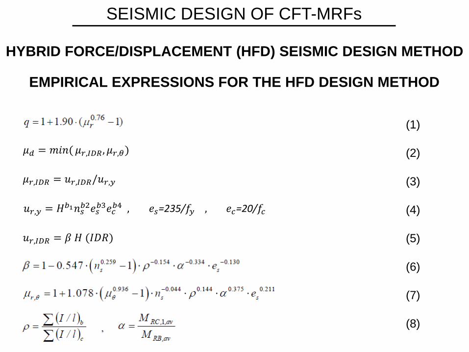
SEISMIC DESIGN OF CFT-MRFs
𝜇𝑑 = 𝑚𝑖𝑛( 𝜇𝑟,𝐼𝐷𝑅 , 𝜇𝑟,𝜃)
𝜇𝑟,𝐼𝐷𝑅 = 𝑢𝑟,𝐼𝐷𝑅/𝑢𝑟,𝑦
𝑢𝑟,𝑦 = 𝐻𝑏1𝑛𝑠𝑏2𝑒𝑠
𝑏3𝑒𝑐𝑏4 , 𝑒𝑠=235/𝑓𝑦 , 𝑒𝑐=20/𝑓𝑐
𝑢𝑟,𝐼𝐷𝑅 = 𝛽 𝛨 (𝐼𝐷𝑅)
(1)
(2)
(3)
(4)
(5)
(6)
(7)
(8)
HYBRID FORCE/DISPLACEMENT (HFD) SEISMIC DESIGN METHOD
EMPIRICAL EXPRESSIONS FOR THE HFD DESIGN METHOD
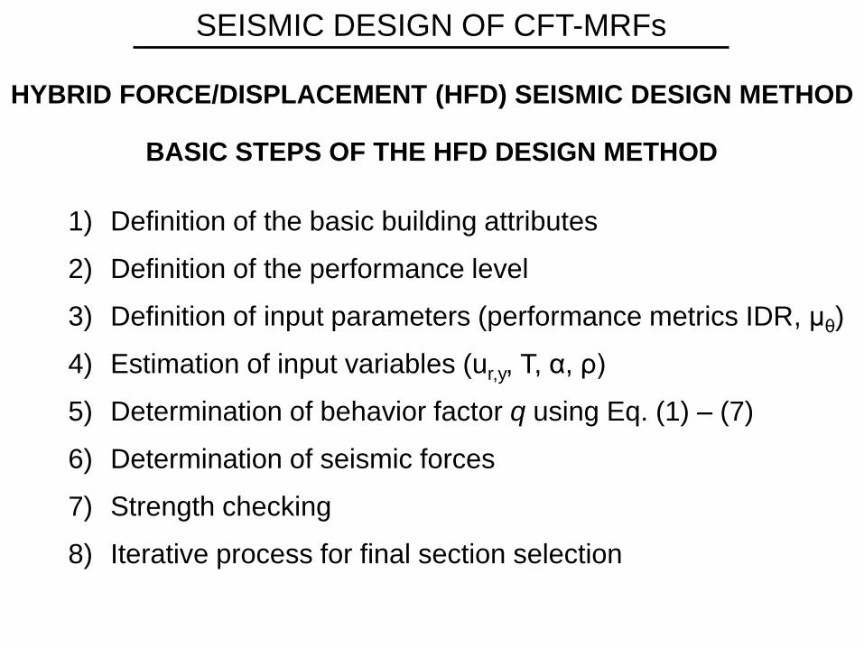
1) Definition of the basic building attributes
2) Definition of the performance level
3) Definition of input parameters (performance metrics IDR, μθ)
4) Estimation of input variables (ur,y, T, α, ρ)
5) Determination of behavior factor q using Eq. (1) – (7)
6) Determination of seismic forces
7) Strength checking
8) Iterative process for final section selection
SEISMIC DESIGN OF CFT-MRFs
HYBRID FORCE/DISPLACEMENT (HFD) SEISMIC DESIGN METHOD
BASIC STEPS OF THE HFD DESIGN METHOD
SEISMIC DESIGN OF CFT-MRFs
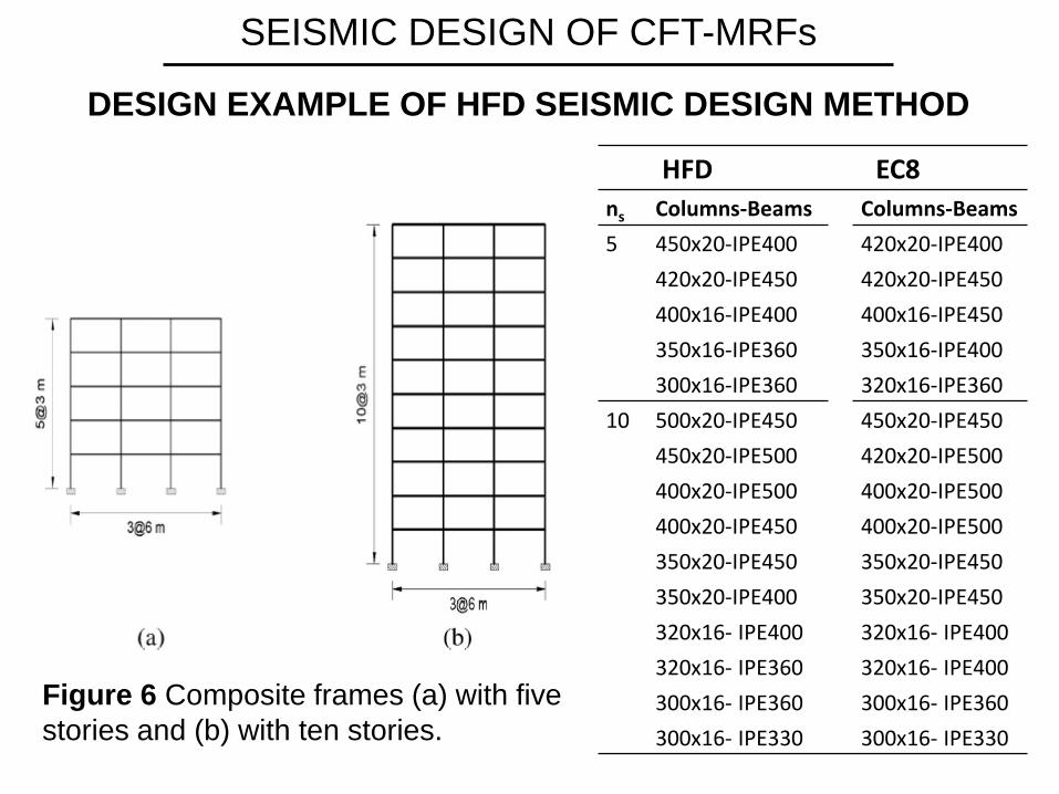
DESIGN EXAMPLE OF HFD SEISMIC DESIGN METHOD
HFD EC8
ns Columns-Beams Columns-Beams
5 450x20-IPE400
420x20-IPE450
400x16-IPE400
350x16-IPE360
300x16-IPE360
420x20-IPE400
420x20-IPE450
400x16-IPE450
350x16-IPE400
320x16-IPE360
10 500x20-IPE450
450x20-IPE500
400x20-IPE500
400x20-IPE450
350x20-IPE450
350x20-IPE400
320x16- IPE400
320x16- IPE360
300x16- IPE360
300x16- IPE330
450x20-IPE450
420x20-IPE500
400x20-IPE500
400x20-IPE500
350x20-IPE450
350x20-IPE450
320x16- IPE400
320x16- IPE400
300x16- IPE360
300x16- IPE330
Figure 6 Composite frames (a) with five
stories and (b) with ten stories.
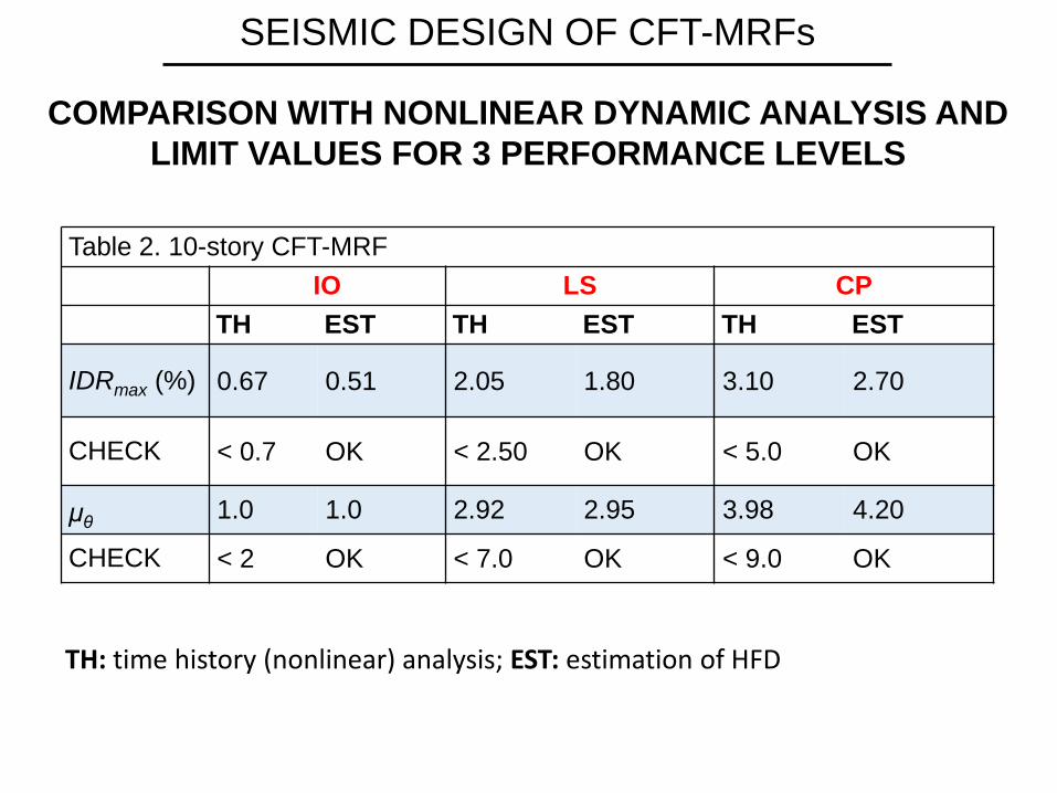
SEISMIC DESIGN OF CFT-MRFs
COMPARISON WITH NONLINEAR DYNAMIC ANALYSIS AND
LIMIT VALUES FOR 3 PERFORMANCE LEVELS
Table 2. 10-story CFT-MRF
IO LS CP
TH EST TH EST TH EST
IDRmax (%) 0.67 0.51 2.05 1.80 3.10 2.70
CHECK < 0.7 OK < 2.50 OK < 5.0 OK
μθ 1.0 1.0 2.92 2.95 3.98 4.20
CHECK < 2 OK < 7.0 OK < 9.0 OK
TH: time history (nonlinear) analysis; EST: estimation of HFD

• Consider as example the Park-Ang (1985) damage index of the
form m
PA
u y u
D dEQ
δm = maximum deformation
δu = ultimate deformation under monotonic loading.
∫dE = dissipated energy
Qy = yield strength
β = constant (0.12 – 0.3)
• Utilizing the previously described response databank for CFT-
MRFs one can obtain the following empirical expression for D
(Kamaris et al 2016)
DAMAGE INDEX EMPIRICAL EXPRESSION
SEISMIC DAMAGE ASSESSMENT OF CFT-MRFs
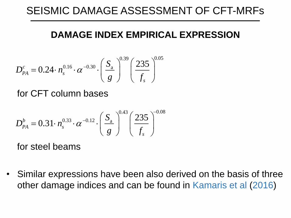
• Similar expressions have been also derived on the basis of three
other damage indices and can be found in Kamaris et al (2016)
0.050.39
0.16 0.30 a 2350.24c
PA s
s
SD n
g f
for CFT column bases
0.080.43
0.33 0.12 a 2350.31b
PA s
s
SD n
g f
for steel beams
DAMAGE INDEX EMPIRICAL EXPRESSION
SEISMIC DAMAGE ASSESSMENT OF CFT-MRFs

SEISMIC DAMAGE ASSESSMENT OF CFT-MRFs
Damage
Index
“Exact”
Value
Approx.
Value Error (%)
DPAM 0.157 0.187 16.0
Damage indices for column bases.
Damage
Index
“Exact”
Value
Approx.
Value Error (%)
DPAM 0.355 0.335 5.6
Damage indices for beams.
DAMAGE INDEX EVALUATION EXAMPLE
3 storey/3 bay CFT-MRF under DBE (PGA=0.35g, soil B)
“Exact” refers to NLTH analysis with 8 motions spectrum compatible to the
DBE.
CONCLUSIONS AND FUTURE DEVELOPMENTS
1) Ultra-high strength steel (UHS) improves the seismic
performance of CFT columns by increasing their elastic
deformation capacity and delaying the failure of local buckling.
2) Simple, yet accurate, plastic-hinge models were developed for
square and circular CFT columns including strength and stiffness
deterioration, which can be successfully used for analysis and
design.
3) Development of simplified hysteretic models for other types of
composite members, such as beam/columns with fully or
partially concrete encased steel sections is a subject of future
studies.
4) The seismic performance of a wide range of CFT-MRF
structures under several levels of seismic hazard was
investigated through time-history dynamic analyses.
CONCLUSIONS AND FUTURE DEVELOPMENTS
5) On the basis of the DBD and FBD methods, a new performance-
based seismic design method, the Hybrid Force/Displacement
(HFD) method, was developed for CFT-MRFs.
6) The HFD method utilizes larger behavior factors compared with
those proposed for steel structures by current design codes
thereby leading to more economical designs when using
composite columns.
7) An empirical methodology for a rapid seismic damage
assessment of CFT-MRFs was also developed. Next step is the
combination of this methodology with probabilistic seismic
hazard analysis models to assess the collapse risk of composite
frames.

THANK YOU
FOR YOUR ATTENTION