
SEFA 8 Testing on EBA 4 · This report provides the testing result when performing the SEFA‐8...
21
Prepared by : Chandra Manik Date : June 2008 Revision : 01 Doc Number : 00/SEFA‐8/EBA ‐4/2008 SEFA‐8 Testing on EBA‐4 1. Introduction……………………………………………………………………………… … SEFA is a voluntary international trade association representing member of the laboratory fume furniture, casework, fume hood, and related equipment industry 1 . The association was founded to promote this rapidly expanding industry to improve the quality, safety and timely completion of laboratory facilities in accordance to customer requirements. This report provides the testing result when performing the SEFA‐8 test procedure on EBA‐4 where it is installed as the base cabinet for fume hood named with model EFA‐4. When performing the SEFA‐8 test code, the apparatus that used in this test is not similar as stated in the code but closely adopted without sacrificing the root of the test purpose. When perform the test, the hollow section filled with concrete to replace the steel bars without reducing the requirement weight (as SEFA‐8 stated) while other apparatus chosen as similar with. 2. Purpose…………………………………………………………………………………………….. The main goals from this test are: ‐ Conclude if the EBA‐4 complies to SEFA‐8. ‐ Collect important data and proposed the improvement for future or immediate development. 1 SEFA ‐8 (Scientific Equipment and Furniture Association), year 1999.
Transcript of SEFA 8 Testing on EBA 4 · This report provides the testing result when performing the SEFA‐8...

Prepared by : Chandra Manik Date : June 2008 Revision : 01 Doc Number : 00/SEFA‐8/EBA ‐4/2008
SEFA‐8 Testing on EBA‐4
1. Introduction……………………………………………………………………………… … SEFA is a voluntary international trade association representing member of the laboratory
fume furniture, casework, fume hood, and related equipment industry1. The association was
founded to promote this rapidly expanding industry to improve the quality, safety and
timely completion of laboratory facilities in accordance to customer requirements.
This report provides the testing result when performing the SEFA‐8 test procedure on EBA‐4
where it is installed as the base cabinet for fume hood named with model EFA‐4. When
performing the SEFA‐8 test code, the apparatus that used in this test is not similar as stated
in the code but closely adopted without sacrificing the root of the test purpose. When
perform the test, the hollow section filled with concrete to replace the steel bars without
reducing the requirement weight (as SEFA‐8 stated) while other apparatus chosen as similar
with.
2. Purpose……………………………………………………………………………………………..
The main goals from this test are:
‐ Conclude if the EBA‐4 complies to SEFA‐8.
‐ Collect important data and proposed the improvement for future or immediate
development.
1 SEFA ‐8 (Scientific Equipment and Furniture Association), year 1999.

3. Apparatus……………………………………………………………………………………… . a. Steel Bar replaced with hollow section fillet with cement
b. Chemical ( see section 8.0 of SEFA‐8 :PL:2007)
c. Impact test equipment ( see appendix at section 16 in this report)
d. Razor blade ( see appendix at section 17 in this report)
e. Pencils with specification : 8‐H,7‐H, 6‐H, 5‐H, 4‐H, 3‐H, 2‐H, H, F, HB, B (soft), 2‐B, 3‐B, 4‐
B, 5‐B ( see appendix at section 18 in this report)
f. Emery paper
g. and other auxiliary equipment ( detail can be found SEFA‐8:PL:2007)
4. Result Summary……………………………………………………………………………….. 4.1 Manufacturer information
Title :
Manufacturer infromation Name : ESCO Micro Pte, ltd. Address : 21 Changi South Street 1 Test Address : Telephone : Fax : Date : May 2008 Test Supervisor/Engineer information Name : Chandra Manik
4.2 Test Result
Table 1 SEFA‐8 Test Result No Type of Test Test Result PASS/FAIL Remarks 1 Cabinet load test PASS No permanent damage 2 Cabinet concentrated load test PASS No permanent damage 3 Cabinet torsion PASS Pass without damage 4 Cabinet submersion test PASS Planning to make tub 5 Door hinge test PASS Both hinge pass the test 6 Door impact test PASS No damage to doors 7 Door cycle test PASS At least 100,000 cycle 8 Drawer static test Not performed EBA‐4 has no drawer spec. 9 Drawer and door pull test Not performed EBA‐4 has no drawer spec. 10 Drawer impact test Not performed EBA‐4 has no drawer spec. 11 Drawer internal rolling impact Not performed EBA‐4 has no drawer spec.
Prepared by : Chandra Manik Date : June 2008 Revision : 01 Doc Number : 00/SEFA‐8/EBA ‐4/2008

12 Drawer cycle test Not performed EBA‐4 has no drawer spec. 13 Shelf load test Not performed EBA‐4 has no drawer spec. 14 Chemical spot test PASS No spot to coating 15 Hot water test PASS No coating damage 16 Impact test PASS No permanent damage 17 Paint adhesion on steel PASS 100% coat intack 18 Paint hardness on steel PASS PASS with Hardnes 4‐H
5. Feed Back ……………………… ……………………………………………………….. Based on testing result , the feed back for development are collected as below. ‐ The base cabinet frame should be strengthened (see figure 1) to make it stronger
than before though when tested the deflection is not permanent. Adding hollow
section is the most feasible way to achieved stronger structure.
‐ Based on impact test on coating surface, found that for the coating thickness
around 90 μm, the test result is fail. Based on literature, the thickness of coating
inversely proportional to the coating impact strength. After seek factory
standard, was found that coating thickness about 80 μm is the suitable value.
The coating thickness measured using thickness sensor (see figure 2.)
‐ Figure 1. horizontal frame of the base cabinet that should be strengthen
Strengthen this frame
Prepared by : Chandra Manik Date : June 2008 Revision : 01 Doc Number : 00/SEFA‐8/EBA ‐4/2008

Figure 2. Measuring the coating thickness
Thickness sensor
Using thickness sensor to find the desire value about 80 μm and performed the impact test on its surface, the result is pass and detail can be found in appendix A.
6. References……………………………………………………………………………………….
[1] Recommended practices for plastic laminate laboratory grade furniture, case work, shelving and tables, SEFA‐8‐PL‐2007. [2] Powder coating standard operational procedure, ESCO powder coating department 2008.
Prepared by : Chandra Manik Date : June 2008 Revision : 01 Doc Number : 00/SEFA‐8/EBA ‐4/2008

Appendix
Prepared by : Chandra Manik Date : June 2008
‐APPENDIX‐
1. Cabinet load test 1.1 Purpose of test The cabinet load test will challenge the structural integrity and load bearing capability of the cabinet
construction. This test will demonstrate the ability of the cabinet to support heavy applied loads. This
is not intended to test the functional characteristics of the cabinet under heavy loads.
1.2 Test Procedure Verify that the cabinet is level. Load the cabinet top by using 2000 pounds (907.2 Kg) of solid steel
bars (in this test, replaced with hollow section 100x50 filled with concrete) stacked five high and
spaced per Figure A.1. After ten minutes, unload the cabinet.
Figure A.1 Cabinet load configuration
1.3 Acceptance level The cabinet will have no signs of permanent failure. After the load is removed inspect the levelers.
Any deformation shall not interfere with the function of the leveling system.
This below procedures retyped from SEFA‐8 year 1999

Appendix
Prepared by : Chandra Manik Date : June 2008
1.4 Test Result After ten minutes, the result are : ‐ no damage on leveler and no permanent damage on the base
cabinet ( see figure A.2)
Figure A.2 Cabinet load test result
2 Cabinet concentrated load test 2.1 Purpose of test The purpose of this test is to challenge the functional characteristics of the cabinet when subjected to
a concentrated load on the center of the cabinet top.
2.2 Test Procedure Using solid weights or 10 pound (4.54 Kg) sand bags (per Section #3.1), apply a tota lof 200 pounds
(90.72 Kg) to the top of the cabinet along the cabinet centerline (SeeFigure #3). Operate doors and
drawers.
2.3 Acceptance level Door and drawer operation shall be normal under condition of test load. There shall be no signs of
permanent distortion to front rail, cabinet joinery, doors, or drawers
On testing After testing

Appendix
Prepared by : Chandra Manik Date : June 2008
2.4 Test Result After test (as shown in figure A.3), no damage was found on cabinet joinery, doors, drawers and
permanent distortion.
Figure A.3 Cabinet concentrated load test result
3 Cabinet torsion 3.1 Purpose of test This test will evaluate the structural integrity of the cabinet construction when subjected to torsional load. 3.2 Test Procedure The cabinet shall be tested in its normal upright position, raised not less than four‐inches off the floor
and supported on rear and one front corner.The area of support under the cabinet shall be located
not more than 6" (152.4mm) in from each supported corner. Secure the cabinet diagonally from the
unsupported corner with seven solid steel bars per Section #3.1 (350 pounds (158.76 Kg) of
weight), on the top of the cabinet to prevent overturning. Apply four solid steel bars (200 pounds
[90.72 Kg] of weight) to the unsupported corner for a period of fifteen minutes (See Figure #4).
Remove weight and place cabinet on the floor in its normal upright position. Observe cabinet joinery.
Level the cabinet and measure the face and back of the cabinet across the diagonal corners.
3.3 Acceptance level
When returned to normal position, the operation of the cabinet shall be normal, and there will be no
signs of permanent damage. The difference between the two measurements taken from measuring
the diagonal corners shall be no more than 1/8" (3.175mm).
On testing After testing

Appendix
Prepared by : Chandra Manik Date : June 2008
3.4 Test Result No permanent damage and also the difference between two diagonal corners no more than 10 mm.
Figure A.4 Cabinet torsion result
4 Cabinet submersion test 4.1 Purpose of test This test will demonstrate the ability of a cabinet to resist standing water. Only units that rest on the
floor or a unit where the base is within 2".
4.2 Test Procedure The material thickness along the perimeter of the cabinet shall be measured on 6 (152.4mm)
increments. Record the thickness of the material to be submerged in water. Calculate the arithmetic
mean of the data taken. Place the entire test cabinet in its upright position such that the cabinet is
submerged in a pan filled with 2" (50.8mm) of water. After four hours, remove the unit from the
water immediately measure the thickness of the material at the same points measured initially.
Calculate the new arithmetic mean. After the unit has been allowed to dry, inspect for other damage.
4.3 Acceptance level
The cabinet will show no signs of permanent deformation or deterioration. Increase in thickness shall
not exceed four percent of the initial mean measurements.
4.4 Test Result
According to the test result is pass for submersion test.
On testing After testing

Appendix
Prepared by : Chandra Manik Date : June 2008
5 Door hinge test 5.1 Purpose of test
This test will demonstrate the durability of the door and its hardware (hinge leaf, screws, etc.) to an
applied load of 200 pounds (90.72 Kg).
5.2 Test Procedure
Remove the shelf for this test. With unit and top set as described in Section 4.1 of SEFA‐8, add
sufficient weight to the top in order to prevent overturning. With cabinet door opened 90‐degrees,
hang a sling made up of two 100 pound (45.36 Kg) weights (shot bags or solid weights) over top of the
door at a point 12" (304.8mm) out from the hinge centerline (See Figures #A5‐a and #A5‐b). Slowly
move door through the full cycle of the hinge, up to a 160‐ degree arc. Remove weight and swing
door through its full intended range of motion and close door.
Figure A5‐b. Base cabinet door load

Appendix
Prepared by : Chandra Manik Date : June 2008
Figure A5‐b. Base cabinet door load – top view
51.3 Acceptance level
The open door shall withstand a load of 200 pounds (90.72 Kg) when applied at a point 12"
(304.8mm) from the hinge centerline without significant permanent distortion. Operation of the
door, after test, shall show no significant permanent distortion that will cause binding of the door
or hinges or that will adversely affect operation of the catch *.
* Certain unit configurations require hinge location to be such that load ratings are lower than the
test model. See manufacturer for details.
5.4 Test Result
Testing result : ‐ no significant permanent distortion that damage the hinge and the door .

Appendix
Prepared by : Chandra Manik Date : June 2008
Figure A6. Door hinge test result
6 Door impact test 6.1 Purpose of test This test will demonstrate the resistance of a 240 inch‐pound (27.1 N‐m) impact to the door face.
Only units that extend below the work surface should be subjected to this test. This test should not
be inclusive of glass doors
6.2 Test Procedure
With unit and top set as described in Section # 4.1 in SEFA‐8, add sufficient weight to the top in order
to prevent overturning. A 20 pound (9.07 Kg) sand bag (per Section #3.1 in SEFA‐8) shall be
suspended and dropped to provide an impact of 240 inch‐pounds (27.1 N‐m) at the center of the
closed door. (See Figure A7.)
6.3 Acceptance level
After the test, the door and catch shall operate normally and show no signs of permanent damage
On testing After testing

Appendix
Prepared by : Chandra Manik Date : June 2008
Figure A.7 Base cabinet door impact.
6.4 Test Result
No permanent result to hinge, door. It still work properly, very little bumped cause impact
Figure A.7 Base cabinet door impact result.
On testing After testing
Little bumped Caused impact load

Appendix
Prepared by : Chandra Manik Date : June 2008
7 Door cycle test
1.1 Purpose of test
This test will demonstrate the durability of the door hinge hardware to withstand 100,000 cycles as a
reliable measure for longevity).
1.2 Test Procedure
This test shall be in conformance to the ANSI test procedure A156.9, Grade 1, requirements for cycle
testing of doors. A cycling mechanism shall swing door 90‐degrees. Door shall operate for 100,000
cycles with a speed not greater than 15 cycles per minute.
1.3 Acceptance level
Door shall operate for the full cycle period without deterioration that wil significantly affect the
function of the door. The door shall operate freely without binding.
1.4 Test Result
When tested under 100,000 cycles, the result shown that no permanent damage and malfunction to
the door.
Figure A.8 Door cycles test.
On testing After testing

Appendix
Prepared by : Chandra Manik Date : June 2008
8 Drawer static test This test is not performed since the EBA‐4 has no drawer type. 9 Drawer and door pull test This test is not performed since the EBA‐4 has no drawer type. 10 Drawer impact test This test is not performed since the EBA‐4 has no drawer type. 11 Drawer internal rolling impact This test is not performed since the EBA‐4 has no drawer type. 12 Drawer cycle test This test is not performed since the EBA‐4 has no drawer type. 13 Shelf load test This test is not performed since the EBA‐4 is not shelf type. 14 Chemical spot test
.14.1 Purpose of test
The purpose of the chemical spot test is to evaluate the resistance a finish has to chemical spills
14.2 Test Procedure
Obtain one sample panel measuring 14" x 24" (355.6mm x 609.6mm). The received sample to be
tested for chemical resistance as described herein.
Place panel on a flat surface, clean with soap and water and blot dry. Condition the panel for 48‐
hours at 73+ 3F (23(+ 2(C) and 50+ 5% relative humidity. Test the panel for chemical resistance using
forty‐nine different chemical reagents by one of the following methods.
Method A ‐ Test volatile chemicals by placing a cotton ball saturated with reagent in the mouth of
a 1‐oz. (29.574cc) bottle and inverting the bottle on the surface of the panel.
Method B – Test non‐volatile chemicals by placing five drops of the reagent on the surface of the
panel and covering with a 24mm watch glass, convex side down. For both of the above methods,
leave the reagents on the panel for a period of one hour. Wash off the panel with water, clean with
detergent and naptha, and rinse with deionized water. Dry with a towel and evaluate after 24‐hours
at 73± 3°F (23°±2°C) and 50± 5% relative humidity using the following rating system.
Level 0 ‐ No detectable change.
Level 1 ‐ Slight change in color or gloss.
Level 2 ‐ Slight surface etching or severe staining.
Level 3 ‐ Pitting, cratering, swelling, or erosion of coating. Obvious and significant deterioration.

Appendix
Prepared by : Chandra Manik Date : June 2008
See SEEFA‐8 for detail list for substances in chemical spot test.
14.3 Acceptance level
Results will vary from manufacturer to manufacturer. Laboratory grade finishes should result in no
more than four Level 3 conditions. Suitability for a given application is dependent upon the chemicals
used in a given laboratory.
When performed the spot chemical test, available chemical resources and quality criteria are:
‐ M.E.K ( methyl , Ethyl, Ketone) No coat glossy tearing or damage on coating glossy)
‐ Ethanol No change in colour
‐ NaoH No change in color
‐ Hidcrolic Acid No change in color
‐ Formaldehyd No change in color
‐ Iodosphor No change in color
‐ Phosporic Acid No change in color
‐ Phenol No change in color or no yellow spot found ( this according to Dupont standard)
‐ Zinc phosperic No change in color
14.4 Test Result
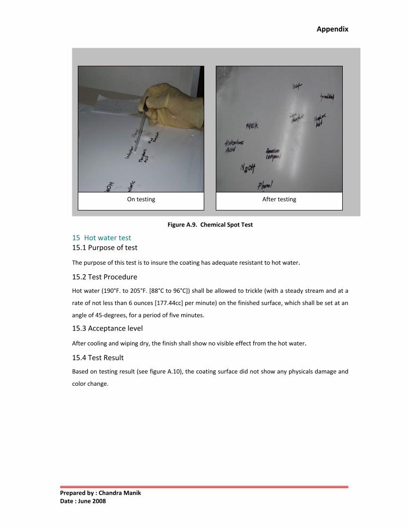
Based on the above chemical test, the result is “PASS” without found any changes in color, shown in
figure A.9.
Table 1. Type of chemical and method for testing
Test No.
Chemical Reagent Method
1. Acetate, Amyl A 2. Acetate, Ethyl A 3 Acetic Acid, 98% B
4. Acetone A 5. Acid Dichromate, 5% B 6. Alcohol, Butyl A 7. Alcohol, Ethyl A 8. Alcohol, Methyl A 9. Ammonium Hydroxide, 28% B
10. Benzene A 11. Carbon Tetrachloride A 12. Chloroform A 13. Chromic Acid, 60% B 14. Cresol A 15. Dichlor Acetic Acid A
16. Dimethylformanide A 17. Dioxane A
Appendix
Prepared by : Chandra Manik Date : June 2008
Figure A.9. Chemical Spot Test
15 Hot water test 15.1 Purpose of test
The purpose of this test is to insure the coating has adequate resistant to hot water.
15.2 Test Procedure
Hot water (190°F. to 205°F. [88°C to 96°C]) shall be allowed to trickle (with a steady stream and at a
rate of not less than 6 ounces [177.44cc] per minute) on the finished surface, which shall be set at an
angle of 45‐degrees, for a period of five minutes.
15.3 Acceptance level
After cooling and wiping dry, the finish shall show no visible effect from the hot water.
15.4 Test Result
Based on testing result (see figure A.10), the coating surface did not show any physicals damage and
color change.
On testing After testing

Appendix
Prepared by : Chandra Manik Date : June 2008
Figure A.10 Hot water test on coating surface.
16 Impact test 16.1 Purpose of test
The purpose of this test is to evaluate the ductility of the coating.
16.2 Test Procedure
A one‐pound ball (approximately 2" [50.8mm] in diameter) shall be dropped from a distance of 12"
(304.8mm) onto a flat horizontal surface, coated to manufacturer’s standard method.
16.3 Acceptance level
There shall be no visual evidence to the naked eye of cracks or checks in the finish due to impact.
On testing After testing
45 o

Appendix
Prepared by : Chandra Manik Date : June 2008
Figure A.11 Impact test equipment
16.4 Test Result According to the test result, first specimen is fail. The failure comes from the coating thickness which
does not meet the factory acceptance level about 90‐100 μm. ESCO had standardized the coating
thickness from 60 to 80 μm.,see figure A.12 for testing result. For the second specimen, the result is
PASS.
Figure A.12 (a) first test (b) Using second specimen with coating thickness average 80 μm
No Visual Crack
(a) (b)
Ball diameter 50.8 mm for impact. test
Complete Impact test equipment

Appendix
Prepared by : Chandra Manik Date : June 2008
17 Paint adhesion on steel 17.1 Purpose of test
The paint adhesion test is used to determine the bond of the coating to steel. This does not apply to
non‐steel products.
17.2 Test Procedure
This test is based on ASTM D2197‐86 “Standard Method of Test for Adhesion of Organic Coating.”
Two sets of eleven parallel lines 1/16" (1.587mm) apart shall be cut with a razor blade to intersect at
right angles thus forming a grid of 100 squares.
The cuts shall be made just deep enough to go through the coating, but not into the substrate. They
shall then be brushed lightly with a soft brush for one minute. Examine under 100‐foot candle of
illumination.
17.3 Acceptance level
Ninety or more of the squares shall show finish intact.
17.4 Test Result
EBA‐4 is pass this test, when performing the test square grids created above specimen and brushed,
the result is 100% grid intact, see figure A.13.
Figure A.13 (a) Making grid above the coating (b) After brushing the grids
100% grid intact
(a) (b)

Appendix
Prepared by : Chandra Manik Date : June 2008
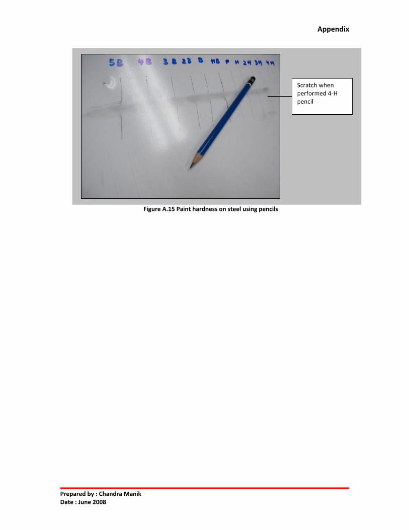
18 Paint hardness on steel 18.1 Purpose of test The paint hardness test is used to determine the resistance of the coatings to scratches.
18.2 Test Procedure Pencils, regardless of their brand, are valued in this way: 8‐H is the hardest, and nex t11order of
diminishing hardness are 7‐H, 6‐H, 5‐H, 4‐H, 3‐H, 2‐H, H, F, HB, B (soft), 2‐B, 3‐B, 4‐B, 5‐B (which are
softest). The pencils shall be sharpened on emery paper to a wide sharp edge. (See Figure A.13)
Pencils of increasing hardness shall be pushed across the paint film in a chisel like manner until one is
found that will cut or scratch the film. The pencil used before that one, that is the hardest pencil that
will not rupture the film, is then used to express or designate the hardness.
18.3 Acceptance level The paint shall have a hardness of 4‐H minimum.
Figure A.14 Cabinet body surface hardness test. 18.4 Test Result After performing the test, the result is pass at minimum 4‐H (see figure A.15).
Appendix
Prepared by : Chandra Manik Date : June 2008
Figure A.15 Paint hardness on steel using pencils
Scratch when performed 4‐H pencil