
SEED DRILL - Agrowplow
53
OPERATOR’S MANUAL AD083 AD130 AD230 AD730 AGROWPLOW | 55 Wellington St, Molong NSW AD#30 Series Manual 2019 Rev16 SEED DRILL
Transcript of SEED DRILL - Agrowplow

OPERATOR’S MANUAL
AD083 AD130 AD230 AD730
AGROWPLOW | 55 Wellington St, Molong NSW AD#30 Series Manual 2019 Rev16
SEED DRILL

A g r o w p l o w O p e r a t o r s M a n u a l P a g e | 2
Contact Details
Agrowplow Pty Ltd
Postal/Office: 55 Wellington St
Molong NSW 2866
Phone: 1300 722 491
Fax: 1300 721 746
Email: [email protected]
Web: www.agrowplow.com
Local Agrowplow Dealer:
‘Prosperity Through Soil Care’

A g r o w p l o w O p e r a t o r s M a n u a l P a g e | 3
Disclaimer
Every effort has been made to ensure that the information in this manual was accurate and up to date at the time of printing. Agrowplow Pty Ltd reserves the right to make subsequent changes to the machine or this manual, where necessary, without notification. Agrowplow Pty Ltd will not be responsible for any damage or consequential loss arising out of misinterpretation or failure to follow recommended procedures. Nor will it be liable for any damage caused by or arising out of modification or misuse of its product. The owner has a responsibility to protect himself and others by observing all safety information and by ensuring all operators are well acquainted with the safety information, trained in the correct use of the machine and applying safe work practices.

A g r o w p l o w O p e r a t o r s M a n u a l P a g e | 4
The Owner’s Manual Your new Agrowplow will give long and efficient service if given normal care and operated properly.
This owner’s manual is provided so that you can become thoroughly familiar with the design of the machine and to obtain information on correct operation, adjustment and maintenance. Only people well acquainted with these guidelines should be allowed to use this machine.
Right and left hand references in this manual are determined by standing behind the machine and facing in the direction of travel.
The manual is considered as part of your machine and must remain with the machine when it is sold.
Delivery Inspection On delivery of your new Agrowplow please check that the machine is not damaged. In cases of shipping damage, please ask your dealer to arrange for the appropriate claim to be lodged immediately.
Assemble any parts supplied loose and inspect your machine with the aid of this manual to familiarise yourself with its features. If you have any queries ask your dealer straight away.
The machine is covered by our 1 year warranty on faulty parts, subject to normal use. Record below the serial number of your machine to help trace the machine and assist us when you order parts.
Model: ________________________________________________________
Serial Number: __________________________________________________
Options:
□ Disc Coulters, Manual lift
□ Disc Coulters, Hydraulic lift
□ Double chuting, Adjustable Flexi Chutes
□ Bean Rollers
□ Press Wheels
□ Harrows
□ Small Seed Box
□ Rear Tow Hitch
□ Hydraulic Lines for Tow Hitch
□ Transport kit with lights

A g r o w p l o w O p e r a t o r s M a n u a l P a g e | 5
Table of Contents Contact Details ................................................................................................................................................................... 2 Disclaimer ........................................................................................................................................................................... 3 The Owner’s Manual .......................................................................................................................................................... 4
Delivery Inspection ......................................................................................................................................................... 4
Table of Contents ............................................................................................................................................................... 5 Table of Figures and Tables ................................................................................................................................................ 7 Agrowplow – Company Profile ........................................................................................................................................... 8 1. Safety .......................................................................................................................................................................... 9
1.1. Shared Responsibility for Safety ........................................................................................................................ 9
1.2. Safe Operation ................................................................................................................................................. 10
1.3. Warning Decals ................................................................................................................................................ 10
1.4. Ergonomic Safety ............................................................................................................................................. 18
1.5. Maintenance .................................................................................................................................................... 18
1.6. Transporting the Machine ............................................................................................................................... 19
1.7. Un-Hitching the Machine................................................................................................................................. 19
1.8. Risk assessment ............................................................................................................................................... 20
2. Operational Expectations and Limitations ............................................................................................................... 22 2.1. Completing Safe Use Instruction (SUI) & Pre Delivery Inspection (PDI) Reports ............................................ 22
3. Machine Setup ......................................................................................................................................................... 23 3.1. Hitching and Levelling ...................................................................................................................................... 23
3.2. Seeding Depth ................................................................................................................................................. 24
3.3. Farmscan Jackal Hectaremeter ........................................................................................................................ 25
3.4. Operating Speed .............................................................................................................................................. 25
3.5. Hopper Selection ............................................................................................................................................. 26
3.6. Optional - Coulter Bar ...................................................................................................................................... 26
3.7. Optional – Lighting and Transport Kit .............................................................................................................. 27
3.8. Optional – Small Seed Box ............................................................................................................................... 27
3.9. Optional – Press Wheels .................................................................................................................................. 27
3.10. Optional – Harrows .......................................................................................................................................... 27
3.11. Rear Tow Hitch ................................................................................................................................................ 28
4. Calibration Instructions ............................................................................................................................................ 28 4.1. Adjusting the Seed and Fertiliser Rates ........................................................................................................... 28
4.2. Method for Checking Metering Rates ............................................................................................................. 31
4.3. Calibration Tables ............................................................................................................................................ 32
4.4. Optional Small Seed Box – Calibration Procedure ........................................................................................... 35
5. Operating Tips .......................................................................................................................................................... 40 5.1. After the First Round ....................................................................................................................................... 40
5.2. Gradual Slowing of Fertiliser Flow ................................................................................................................... 40
5.3. Seizing of the Metering System ....................................................................................................................... 40
5.4. Checking the Rotation of the Drives ................................................................................................................ 40
5.5. Cleaning Seed and Fertiliser Hoppers .............................................................................................................. 40
6. Maintenance ............................................................................................................................................................ 42

A g r o w p l o w O p e r a t o r s M a n u a l P a g e | 6
6.1. Pre-Operation Check ....................................................................................................................................... 42
6.2. Daily Service ..................................................................................................................................................... 42
6.3. Lubrication ....................................................................................................................................................... 42
6.4. Bolts and Hardware ......................................................................................................................................... 42
6.5. Replacing Soil Openers .................................................................................................................................... 43
6.6. Coulter Replacement ....................................................................................................................................... 43
6.7. Downtube Assembly ........................................................................................................................................ 44
6.8. Replacing Adjustable Gates ............................................................................................................................. 44
6.9. Servicing the Fluted Rollers ............................................................................................................................. 44
6.10. Major Servicing of the Metering Mechanism .................................................................................................. 45
6.11. Servicing the Gearboxes .................................................................................................................................. 45
6.12. Drive Chain Adjustments ................................................................................................................................. 45
6.13. Drive Chain Maintenance ................................................................................................................................ 46
6.14. End of Season Storage ..................................................................................................................................... 46
7. Troubleshooting Guide ............................................................................................................................................. 47 7.1. Undercarriage .................................................................................................................................................. 47
7.2. Metering System ............................................................................................................................................. 48
7.3. Hydraulic System ............................................................................................................................................. 48
7.4. Farmscan Jackal Hectaremeter ........................................................................................................................ 49
8. Specifications ............................................................................................................................................................ 50 8.1. AD083 Series Agrowdrill Specifications ........................................................................................................... 50
8.2. AD130 Series Agrowdrill Specifications ........................................................................................................... 50
8.3. AD230 Series Agrowdrill Specifications ........................................................................................................... 51
8.1. AD730 Series Agrowdrill Specifications ........................................................................................................... 51
9. Warranty .................................................................................................................................................................. 52 9.1. Warranty Policy ............................................................................................................................................... 52
9.2. Conditions of Warranty ................................................................................................................................... 52

A g r o w p l o w O p e r a t o r s M a n u a l P a g e | 7
Table of Figures and Tables Figure 1 Hazardous Machinery Decal ............................................................................................................................... 11 Figure 2 Do Not Operate Near Bystanders Decal ............................................................................................................. 11 Figure 3 Rotating or Moving Machinery Decal ................................................................................................................. 12 Figure 4 Hydraulic Fluid Penetration Decal ...................................................................................................................... 12 Figure 5 Heat Source Decal .............................................................................................................................................. 13 Figure 6 Three Point Linkage Decal .................................................................................................................................. 13 Figure 7 Do Not Climb On This Machine Decal ................................................................................................................ 14 Figure 8 Do Not Enter This Area Decal ............................................................................................................................. 14 Figure 9 Engine Driven Components Decal ...................................................................................................................... 14 Figure 10 Chemical Hazard Decal ..................................................................................................................................... 15 Figure 11 Noise Exposure Decal ....................................................................................................................................... 15 Figure 12 Battery Explosion Decal .................................................................................................................................... 16 Figure 13 Tyre Inflation Decal .......................................................................................................................................... 16 Figure 14 Electrical Hazard Decal ..................................................................................................................................... 17 Figure 15 Raised Wing Decal ............................................................................................................................................ 17 Figure 16 Right Hand Wheel Lift Cylinder ........................................................................................................................ 24 Figure 17 Farmscan Jackal Hectaremeter ........................................................................................................................ 25 Figure 18 Rate Adjustment Leavers ................................................................................................................................. 28 Figure 19 Fluted rollers and restrictors ............................................................................................................................ 29 Figure 20 Restrictor positioning ....................................................................................................................................... 30 Figure 21 Pin in Clutch Bar ............................................................................................................................................... 35 Figure 22 Two Nuts which Adjust Choke .......................................................................................................................... 35 Figure 23 Small Seed Box, Seed Rate Scale ...................................................................................................................... 36 Figure 24 Position of Chain in High Gear and Low Gear................................................................................................... 37 Figure 25 Drive shaft mounting bushes ........................................................................................................................... 44 Figure 26 Removing and installing restrictors .................................................................................................................. 45 Figure 27 Gearbox oil level and filler plugs ...................................................................................................................... 45 Table 1 Risk Assessment ................................................................................................................................................... 20 Table 2 Risk Assessment Rating ....................................................................................................................................... 21 Table 3 Recommended Restrictor and Gate Settings ...................................................................................................... 30 Table 4 AD083 Series Agrowdrill Calibration Data ........................................................................................................... 32 Table 5 AD130 Series Agrowdrill Calibration Data ........................................................................................................... 32 Table 6 AD230 Series Agrowdrill Calibration Data ........................................................................................................... 32 Table 7 AD730 Series Agrowdrill Calibration Data ........................................................................................................... 32 Table 8 Lubrication Schedule ........................................................................................................................................... 42 Table 9 Wheel Nut Torque Chart ..................................................................................................................................... 43 Table 10 Standard Torque Chart ...................................................................................................................................... 43 Table 11 Troubleshooting Guide for Undercarriage ........................................................................................................ 47 Table 12 Troubleshooting for Metering System .............................................................................................................. 48 Table 13 Troubleshooting for Hydraulic System .............................................................................................................. 48 Table 14 Troubleshooting for Farmscan Jackal Hectaremeter ......................................................................................... 49 Table 15 AD130 Series Agrowdrill .................................................................................................................................... 50 Table 16 AD130 Series Agrowdrill .................................................................................................................................... 50 Table 17 AD230 Series Agrowdrill .................................................................................................................................... 51 Table 18 AD730 Series Agrowdrill .................................................................................................................................... 51

A g r o w p l o w O p e r a t o r s M a n u a l P a g e | 8
Agrowplow – Company Profile
Agrowplow Pty Ltd is an innovative, soil conscious company committed to developing "Soil Care" products for improved, sustainable agriculture.
The founders of Agrowplow had the foresight to see that farmers needed to improve their practices if farming was to be sustainable.
The first Agrowplow was designed and built in 1977 to improve soil structure, increase humus levels and increase water infiltration and storage deep into the soil.
Today the company's range of Agrowplows and Agrowdrills are widely accepted by farmers and agricultural researchers for their unique capabilities. The term "Agrowplow" has become a "farming concept" rather than just another implement.
The company's range of specialised Agrowplows, Agrowdrills and other products are designed and manufactured under strict code of sustainable agricultural mechanisation, and promoted under the slogan:
"Prosperity Through Soil Care"
The company's research and development division develops world leading technology for Agrowplow which has resulted in a well-earned reputation of turning market "Ideas" into reality.
Development is undertaken with the professional guidance of fully qualified design engineers with the use of 3D CAD/CAM that supports the complete design to manufacture process. All designs are manufactured to the highest standards of quality control.
Agrowplow has a large factory area (3500 square metres) with extensive fabrication equipment. Experienced and qualified personnel form an extensive resource in all areas.
Agrowplow - building soil care products for improved, sustainable agriculture.

A g r o w p l o w O p e r a t o r s M a n u a l P a g e | 9
1. Safety Agricultural machinery presents an operator with hazards associated with setting up, on and off road transport, tillage and seeding applications, as well as machine service and maintenance. The operator must be aware of these hazards.
The dealer will explain the capabilities, safe application, service requirements and restrictions of the machine and demonstrate the safe operation of the machine according to Agrowplow’s instructions. The dealer can also identify unsafe modifications or use of unapproved attachments.
The following publications provide information on the safe use and maintenance of the machine and attachments:
• The operator’s manual delivered with the machine gives operating information as well as routine maintenance and service procedures. It is a part of the machine and must stay with the machine if it is sold. Replacement operator’s manuals can be down loaded from the Agrowplow website.
• The machine has decals that instruct on safe operation and care.
1.1. Shared Responsibility for Safety 1.1.1. Why is farm safety important?
Farming is dangerous. Farms have many conditions that create dangerous situations including increasing use of machines and chemicals, confined spaces, live animals, constantly changing weather conditions, very young and very old people and continual financial pressure to get crops in and harvest off on time. As any combination of these factors can become lethal, control of occupational health and safety risks has become an essential farm management competency.
Taking risks with the lives of family members or employees is not something that should ever be contemplated!
Farm accidents are often workplace accidents of a different kind. While any workplace accident is a tragedy, a farm accident is often a family disaster where a breadwinner, grandparent, child or other family member is injured or killed. At times the tragedy is made worse by the fact that another family member may have caused the accident and is charged with an offence under occupational health and safety legislation.
Considering that the likelihood of an accident can be significantly reduced by people being more safety conscious, safety should be a topic of frequent discussion among family members and farm employees. Children also need to be trained to recognise hazards and to never use machinery as a plaything, as they too can play a role to remind others to never take safety risks. The loss of fun that kids might otherwise have on machinery is nothing compared to the grief of harm done to a child.
1.1.2. Four Big Reasons Why Safety Is Important • Accidents Hurt
• Accidents Cost
• Accidents Involve Others
• Accidents Can Be Avoided
1.1.3. How to Create Safety Awareness The Safety slogan – ‘Think it, Talk it, Work it’, summarises what we all must do to make workplaces that are without risk to the extent that is reasonably practicable. Assuming that the chain of responsibility is working as it should, machinery will be properly guarded, safety switches fitted and proper information given by way of Operator Handbooks, decals, verbal instruction and so on to all relevant personnel.
Risk awareness and proper use of a machine is the result of an employer having been given relevant information, taking safety seriously, and ensuring that each operator of a machine is properly trained and supervised.
1.1.4. Consultation Providing information is a good beginning. Each employee must then be free to further discuss safety related matters and ask for further assistance from your employer, Health and Safety Representative, or workplace OH&S Authorities if required. Consultation is always best if it is done cooperatively, as part of the way business is normally done, at smoko discussions or at more formal meetings depending on the topic and your business situation.

A g r o w p l o w O p e r a t o r s M a n u a l P a g e | 10
Ultimately, we are only safe at work when everyone who is responsible for safety has played their part and the employer, supervisor and the person using a hazardous machine “thinks it, talks it and works it”. Safe working conditions are the result of a safety culture in which everyone participates, where it would be unacceptable to behave any other way.
1.1.5. Hazard Identification A hazard is something that has the potential to cause harm to a person. Where you are now there may be hundreds of hazards. Some hazards have so little potential for harm, due to their likelihood, that we can disregard them. Other hazards, because of the real and likely potential for serious harm, must not only be identified, but also controlled so as to eliminate or reduce the potential for harm to a person.
1.2. Safe Operation This section offers general guidelines for the safe operation of machinery. It does not replace local, state or federal safety regulations.
Agrowplow has made every effort to highlight all risks to personnel or property. Owners and operators have a responsibility to exercise care and safe work practices at all times in the vicinity of the machine. Owners are advised to keep up to date on safety issues and to communicate these to all users of the machine. If you have safety concerns specifically related to this machine, contact your dealer immediately.
1.2.1. Operator Safety Read this manual carefully before operating new equipment. Learn how to use this machine safely. Be thoroughly familiar with the controls and the proper use of the equipment before using it.
Take careful note of all safety instructions both in this manual and on the machine itself. Failure to comply with
instructions could result in personal injury and / or damage to the machine. Replace missing or damaged safety
decals on the machine and ensure that these remain clearly visible.
It is the owner’s responsibility to ensure that anyone who operates, adjusts, lubricates, maintains, cleans or uses the
machine in any way has had suitable instruction and is familiar with the information in this manual. Operators and
other users of the machine should be aware of potential hazards and operating limitations.
1.2.2. Have Training with Actual Operation • Operator training must consist of a demonstration and verbal instruction.
• This training is given by your dealer when the machine is delivered.
• New operators must start in an area without bystanders and use all the controls until they can operate the machine safely under all conditions of the work area.
1.2.3. Know the Work Conditions • Operators must know any prohibited uses or work areas. They need to know about excessive slopes and
rough terrain.
• Operators must know the local road transport regulations, and understand the dangers and requirements of transporting wide and heavy equipment.
• Always wear protective clothing when servicing the machine.
• For operators to be qualified, they must not use drugs or alcoholic drinks that impair their alertness or
coordination while working. Operators who are taking prescription drugs must get medical advice to
determine if they can safely operate a machine.
1.3. Warning Decals Safety Warning Decals are a means of communication the presence of hazards and appropriate risk controls to machinery operators.
• Do not remove any safety instruction decals.
• Ensure that any safety decals are clear and visible. Clean and replace as necessary.

A g r o w p l o w O p e r a t o r s M a n u a l P a g e | 11
1.3.1. Hazardous Machinery Misuse or incorrect operation on any machine could cause serious injury or death to either the operator or bystanders. It is important to always fully read the Operator’s Manual and understand all operating and safety procedures before using the machine. If you have any queries relating to safety or the operation of any machine contact your Agrowplow dealer immediately.
All guards and safety devices must be kept on the machine and maintained in a functional condition. If necessary to remove guards or safety devices for maintenance they must be replaced before commencing operation.
Sound the horn before starting the machine and before moving off to alert bystanders of your intentions. Bystanders must also be well clear of the machine before operating.
Figure 1 Hazardous Machinery Decal
If the machine is to be left unattended the hydraulics must be lowered and the engine stopped. This will prevent accidental operation of the machine.
1.3.2. Bystanders
Figure 2 Do Not Operate Near Bystanders Decal
Do not operate any agricultural machinery near bystanders. Serious injury or death to bystanders could occur if they come in contact with projectiles, chemical spray, fertiliser and/or grain dust and moving machinery.
Sound the horn before starting the machine and before moving off to alert bystanders of your intentions. Make sure bystanders are well clear of the machine before operating.

A g r o w p l o w O p e r a t o r s M a n u a l P a g e | 12
1.3.3. Machinery Safety Guards
Figure 3 Rotating or Moving Machinery Decal
Safety hazards related to exposed drive belts, pulleys, chains, sprockets and other mechanisms must be clearly identified and properly guarded. Some hazardous mechanisms like tynes and coulter discs cannot carry out their intended function if they are guarded and must, therefore, be controlled by an alternative means. Guards must be fixed in place with bolts, locks or fasteners that require a tool or key to remove them.
Always wear Personal Protective Equipment (PPE) including overalls whilst operating the machine. Loose items of clothing, jewellery (including watches), or long hair could all become entangled in rotating or moving parts causing serious injury or death.
Keep clothing and body extremities well clear of pinch points while the machine is operating. Keep well clear of moving parts at all times. These include drive chains, sprockets, shafts, wheels, discs, pivot points, etc. Guards are provided with the machine for safety reasons where practical without compromising machine performance. Ensure these are always fitted during operation.
1.3.4. Hydraulic Fluid Penetration
A hydraulic fluid leak can, under high pressure, penetrate a human body
Appropriate risk controls must be established to safe guard against hydraulic fluid penetration. All hydraulic machinery should be inspected regularly. Worn hoses and faulty connections, valves or cylinders, must be repaired or replaced.
Operators should be warned that, in some cases, residual pressure can remain in a hydraulic system after it is shut down. In these situations the cause of the residual pressure needs to be identified and controlled to avoid the possibility of a high pressure hydraulic fluid leak or the unintended operation or movement of the machine or attachment.
Figure 4 Hydraulic Fluid Penetration Decal
Relieve the pressure before disconnecting any hydraulic or other lines. Make all repairs and tighten all fittings before re-connection to pressurised fluid. Keep your hands and body away from any pinholes or high pressure jets. Search for leaks with a piece of cardboard instead of using your hand directly.

A g r o w p l o w O p e r a t o r s M a n u a l P a g e | 13
Avoid any contact with fluids leaking under pressure, because the fluids can penetrate the skin surface. Any fluid which penetrates the skin will need to be removed immediately by a medical expert. Seek specialist advice on this type of injury.
To eliminate the risk of serious injury or death:
• Repair or replace all possible causes of leaking hydraulic fluid, including: o Faulty valves, cylinders and components; o Worn hoses and fittings.
• Train operators to shut down pressure pumps or pressure sources before coupling or uncoupling hydraulic connectors
• Never use bare hands to check hoses for leaks. Use a piece of paper to detect a high pressure spray
• Use Personal Protective Equipment.
Instruct operators to wear protective equipment, including safety glasses, if there is a high likelihood of a high pressure hydraulic leak.
1.3.5. Hot Components During operation hydraulic components such as motors, pumps and valve blocks can become quite warm. Do not touch these components until they have cooled down otherwise serious injury such as burns could result.
Figure 5 Heat Source Decal
1.3.6. Three Point Linkage
Figure 6 Three Point Linkage Decal
The three point linkage on a tractor creates numerous pinch and crush points that could cause serious injury or death. Keep well clear of this area when the engine is running.
Shut the engine off for all attachment, un-attachment and maintenance in this region.

A g r o w p l o w O p e r a t o r s M a n u a l P a g e | 14
1.3.7. Service Access Using incorrect access points could result in serious injury or death as a result of slipping and / or falling. Agricultural machinery contains many sharp edges and points. Some of these can and should be guarded, whilst other sections cannot be guarded without compromising the working function of the machine.
Always use access platforms and access ladders to carry out maintenance or refilling. If maintenance is required on parts of the machine not serviced by an access platform always use a ladder or some other form of access device.
Figure 7 Do Not Climb On This Machine Decal
Do not ride on, or allow passengers on, the machine. Under no circumstances are passengers to be permitted on the machine while it is in operation or being transported. Any platforms and/or steps are provided solely for the purpose of preparing the machine for use.
Figure 8 Do Not Enter This Area Decal
Always shut the engine off before climbing into, onto or under machinery. If engines are operating power could accidently be directed to components in these areas and cause serious injury or death.
Always keep clothing and hands clear of all engine driven components. Serious injury or death could result by contact with fast or powerful components.
Figure 9 Engine Driven Components Decal

A g r o w p l o w O p e r a t o r s M a n u a l P a g e | 15
1.3.8. Handle Agricultural Chemicals Safely
Figure 10 Chemical Hazard Decal
All farm chemicals including fertilisers should be stored, used, handled and disposed of safely and in accordance with the manufacturer’s recommendations. Read the product label before using, noting any warnings or special cautions, including any protective clothing or equipment that may be required.
Do not eat or smoke while handling chemicals, fertilizers or coated seeds. Always wash your hands and face before you eat, drink or use the toilet.
Store chemicals, fertilizers and coated seeds out of reach of children and pets, and away from food and animal feeds. Any symptoms of illness during or after using chemicals should be treated according to the manufacturer’s recommendations. If severe, call a physician or get the patient to hospital immediately. Keep the container and/or label for reference.
1.3.9. Controlling Noise
Figure 11 Noise Exposure Decal
Excessive noise levels can cause permanent hearing impairment. The incidence of hearing impairment increases as the exposure to noise increases. Noise levels are cumulative and increase with each extra noise.
Noise can be reduced by eliminating sounds. Isolate noisy operations by making sure that they are carried out away from other people.
Provide sound reducing equipment such as a cab on a tractor. Avoid using noisy equipment if possible.
Use warning signs to remind people to wear hearing protection and reduce noise. Have staff that work in noisy environments undergo an annual hearing check.
Always wear earplugs, or similar devices, when carrying out noisy activities.
1.3.10. Battery Explosion Automotive lead/acid batteries may explode when improperly handled or used. Explosion may cause a person to be injured by the force of the explosion or a spray of sulphuric acid to their face or body.

A g r o w p l o w O p e r a t o r s M a n u a l P a g e | 16
Battery explosion may occur due to:
• Severe over heating due to overuse;
• A metal object being dropped on a battery causing a short circuit;
• A spark igniting hydrogen gas emitted when being charged;
• A spark igniting hydrogen gas when a battery is being installed or when jumper leads are applied.
Figure 12 Battery Explosion Decal
Operators must wear protective eye wear, gloves and clothing when handling or connecting batteries.
Batteries should always be covered when installed.
The final connection of a battery should always be the earth lead to the chassis or engine black, not to the battery.
1.3.11. Tyre Inflation Tyres must not be inflated with unregulated air pressure where the pressure could exceed limits specified by a manufacturer.
Tyre inflation must always be observed by a competent operator to ensure the following is correct:
• Tyre to rim fitment
• Tyre / bead lubrication
• Bead seating
• Inflation pressure.
Figure 13 Tyre Inflation Decal
An operator must always face the tyre tread from the side and not from the face and no operator should stand in the blast trajectory of any tyre during inflation. The blast trajectory is the area in front of the wheel face.
Tyre explosion may be due to:
• Improper fitting of the tyre
• Improper fitting or damage to the rim or locking ring
• Excessive air pressure
• Inflation of damaged tyres or rims. Damaged tyres or rims must not be inflated until the damaged item is replaced or repaired to the satisfaction of a competent person Used tyres must be inspected inside and out

A g r o w p l o w O p e r a t o r s M a n u a l P a g e | 17
prior to fitment. Rims must be clean, free of rust, not cracked, distorted or improperly repaired. Do not inflate over 35psi to seat beads
• Unknown damage to the tyre casing causing a zipper effect casing failure
• Tyre / wheel incompatibility. Tyres must only be fitted to rims for which they are verified as being compatible by a competent person
• No lubrication. Tyres must always be lubricated with a suitable lubricant that allows proper seating without damage to the tyre or the use of excessive pressure.
1.3.12. Electrical Hazards
Figure 14 Electrical Hazard Decal
Contact with overhead power lines or other electrical supplies or devices can cause serious injury or death. Avoid contact with these objects at all times.
Look Up and Live!
1.3.13. Raised Wings
Figure 15 Raised Wing Decal
A failure of the wings mechanical lock or a failure in the hydraulic circuit can cause the rapid collapse of the wing itself. Contact with a falling wing can cause serious injury or death by crushing, impalement or other forms of trauma.

A g r o w p l o w O p e r a t o r s M a n u a l P a g e | 18
1.4. Ergonomic Safety 1.4.1. Personal Protective Equipment
Employers must provide a safe workplace for their employees.
Employers are responsible to ensure that Personal Protective Equipment (PPE) is available for use in situations where it makes a practical contribution to controlling hazards and safety risks.
Employers must also ensure that PPE is in good condition and is properly used by employees.
1.4.2. Working at Heights Where work is required at heights where a fall of more than two meters is possible, operators must be aware of hazards caused by:
• Unstable, sloping or slippery surfaces;
• Proximity to unguarded edges;
• Other non-fall hazards.
Risks must be controlled by the most practicable of the following means:
• Do the task at ground level
• Use suitable equipment that provides a solid elevated working surface
• Use fall prevention system (safety harness)
Ladders are the least preferred means of working at heights and should only be used when there is no viable alternative such as:
• Stairs
• Cherry picker
• Portable steps
• Forklift with appropriate platform
• Scaffold
Emergency procedures including first aid must be available.
A safety harness must also be used where required by the nature of the task.
Where employees must work at height in situations including servicing of machines proper equipment, such as a ladder and proper training in its use and emergency procedures must be provided.
In other situations where employees must often or always work at height a proper scaffold or mobile platform must
be provided which provides a solid working surface. Other potential hazards that may cause falls, such as fatigue
from using a spray gun and exposure to paint fumes must be minimised.
1.5. Maintenance 1.5.1. Practice Safe Maintenance
Keep the machine in safe working condition. Routine maintenance and regular servicing will help reduce risks and prolong the life of the machine. General Maintenance Accidents occur most frequently during servicing and repair. The following general rules must be followed when maintaining or working with machinery:
• All operating and maintenance manuals must be read before and referred to while using or servicing any piece of equipment.
• Turn off all machinery power sources and isolate the machine before making adjustments, doing lubrication, repairs or any other maintenance on the machine.
• Ensure that the machine hydraulics are disconnected from the power source.
• Wear gloves when handling components with cutting edges, such as any ground cutting components.
• Beware of hazards created by springs under tension or compression when dismantling or maintaining the machine.
• It is recommended that you clean the machine before commencing maintenance.

A g r o w p l o w O p e r a t o r s M a n u a l P a g e | 19
• When machinery is fitted with hydraulics, do not rely on the hydraulics to support the machine. During maintenance or while making adjustments under the machine, always lock the hydraulics and support the machine securely.
ALWAYS FIT SAFETY STOPS WHEN WORKING ON MACHINES.
• Place blocks or other stable supports under elevated parts before working on these.
• Extreme caution should be used when clearing coulters, tynes or soil openers. These may be very sharp and cause serious injury.
• Use due care when adjusting or maintaining any aspect of the Agrowdrill. Failure to do so may result in serious injury.
1.5.2. Electrical Maintenance Disconnect the electrical supply from the tractor before doing any electrical maintenance. When welding with electronic equipment in modern tractors and on machinery it is advisable to disconnect the machine from the tractor or at least disconnect the alternator and battery before attempting any welding.
1.6. Transporting the Machine Ensure that all linkage pins and security clips are fitted correctly. With trailing machines tow with the drawbar only as this is the only safe towing point on the machine. Always check that bystanders are clear before starting and moving the tractor and the machine. Plan safe routes of travel, and be aware of power lines and other roadside hazards. Take particular care when towing implements on hillsides.
DO NOT PULL TRAILED AGROWDRILLS WITH ANY VEHICLE OTHER THAN A TRACTOR.
In most instances the weight of the Agrowplow exceeds the unbraked towing capacity of the tow vehicle (except
tractors). Not only is this unsafe it will also void the vehicle manufacturer’s warranty.
Do not ride or allow passengers on the machine. This machine is not designed to carry passengers and therefore no riders are permitted at any time.
Please consult your local transport authority regarding the use of ‘Oversize’ signs, escort vehicles and lighting equipment when transporting agricultural machines on public roads.
When transporting the machine:
• A speed of 30 km/h must not be exceeded. Transporting at greater speeds will result in loss of implement control and cause serious damage or injury.
• Do not transport the Agrowdrill without the tractor drawbar being in a locked position. Transporting without the drawbar locked will result in loss of implement control and serious damage or injury.
• Do not transport an Agrowdrill with a vehicle of less gross mass than that of the Agrowdrill being towed. Transporting with a smaller lead vehicle will result in loss of implement control and cause serious damage or injury.
• Make sure the Agrowdrill does not exceed the unbraked towing capacity of the lead vehicle.
• Do not pull trailed Agrowdrills from any point other than from the tractor drawbar. Pulling from a point other than the designated tractor drawbar can result in tractor instability and cause serious damage or injury.
• Do not operate when visibility is limited e.g. in foggy conditions. Do not operate outside daylight hours unless lights are fitted.
• Please consult your local road transport authority for road use e.g. Oversize Transport.
• Avoid holes, ditches and obstructions which may cause the machine to tip over, especially on hillsides.
• Never drive near the edge of a gully or steep embankment as it might cave in.
• Slow down for hillsides, rough ground and sharp turns.
1.7. Un-Hitching the Machine When unhitching the Agrowplow:
• Always unhitch on a solid, flat surface
• Always lower the hydraulics of the machine. The Agrowdrill is more stable when the undercarriage is resting on the ground than if it is left in the raised position. Machines left in the raised position are susceptible to hydraulic failure causing the machine to crash to the ground and a rapid discharge of pressurised hydraulic

A g r o w p l o w O p e r a t o r s M a n u a l P a g e | 20
fluid. Lowering the Agrowdrill to the ground will also relieve pressure from the hydraulic circuit making it safer and easier to connect and disconnect the hydraulic couplings.
• Always place chocks behind and in front of the wheels to prevent accidental movement on the machine.
• Always lower the jack stand to 'take the weight' of the A-frame. This will provide further stability to the parked Agrowplow.
1.8. Risk assessment Practicing an attitude of safety will require all operators are trained in performing risk assessments. A risk assessment must be performed for any new task or change in routine. It is also recommended that risk assessments be performed (even if only mentally) for all routine tasks and any occasion of usage. It is the owner’s responsibility to ensure the machine is used safely.
The table on the next page is a guide to assess the severity of hazards associated with the machines use. The columns listed include:
• Hazard Type – lists hazards for assessment and notes whether they are relevant to the machine
• Cause of Hazard – lists the area or application of the machine which applies to the hazard
• Risk Control – lists appropriate safety measures to protect personnel and equipment from damage or harm
The risk assessment rating is calculated from the following table by taking the value for ‘Risk Severity’ and adding it to the value for ‘Likelihood of Occurrence’.
RISK ASSESSMENT Rate the severity & likelihood of any hazards present within the machine
RISK SEVERITY 4 = Possible fatality 3 = Major injury 2 = Minor injury 1 = Negligible injury
LIKELIHOOD OF OCCURRENCE
4 = Very likely 3 = Likely 2 = Unlikely 1 = Very unlikely
FREQUENCY If the exposure to a hazard is very frequent e.g. continuous, compared to weekly, monthly etc., this should be reflected in increased likelihood of occurrence.
Add the Risk Severity to the likelihood of Occurrence to calculate the Risk Assessment Rating
Table 1 Risk Assessment
The Risk Control measures listed should be in accordance with the following risk assessment ratings:
• 1 to 2 – Low Risk, Acceptable Hazards Issues to be reviewed with regularity but no specific action is required. Machine usage with awareness.
• 3 to 4 – Medium Risk, Hazards to be managed Decals or warning signage should be fixed in reasonable locations. All personnel who interact with the machine should be warned of the hazard. Operators to be trained to never operate machine when safety measures are not being adhered to.
• 5 and higher – High Risk, Unacceptable Hazards Operators must be trained to check that no risk of this hazard is present before or while using machine and must never use the machine when any risk of this hazard is present.

A g r o w p l o w O p e r a t o r s M a n u a l P a g e | 21
HAZARD TYPE CAUSE OF HAZARD RISK CONTROL
Is there a potential for injury or illness due to …
YES or NO
What is the cause or source of the hazard …
RISK ASSESS RATING
Determine and apply appropriate risk controls after considering Hierarchy of Risk Control
ENTANGLEMENT
YES
Moving chains or belts 3 + 3 = 6 Replace guards after maintenance
Entanglement, drawing in, pinching or trapping
Rotating augers & similar mechanisms for moving seed fertiliser
3 + 2 = 5
Do not operate if personnel can reach moving parts.
CRUSHING OR IMPACT
YES
Attachment of machinery to tractor with 3pt link or hitch
3 + 2 = 5
Clearly view crush area when reversing tractor toward machinery Apply hydraulic and wheel chocks before performing maintenance
Crushing or impact during operation
STRIKING OR IMPACT An object striking the operator or another person
YES
Material discharge from tyne, striking rock or spring recoil 1 + 2 = 3
Do not operate with personnel in close proximity to drill
CUTTING A cutting, stabbing or shearing YES
Tyne point in operation, shearing against ground 4 + 1 = 5
Do not operate with personnel under drill
SLIPPING - PERSONNEL slipping, tripping or falling YES
Climbing on machine platform
2 + 2 = 4
Apply 3 points of contact for access at all times
SLIPPING - MACHINERY uncontrolled machine movement YES
Travelling over slopes, slippery or sodden ground 3 + 1 =4
Use tractor of equal or greater weight than towed weight See Tractor hazard control
EXPOSURE Exposure to vibration, heat, radiation, friction or abrasion
NO
Heat from tractor, see tractor hazard control
NOISE Excessive noise YES
Operation noise 1 + 1 = 2
Apply hearing protection if noise becomes hazardous
HIGH PRESSURE FLUID PENITRATION Hydraulic fluid leak YES
Hydraulic tube or fitting leaking high pressure oil (drills with hydraulic system only) 3 + 1 = 4
Inspect hydraulic system for leaks using appropriate caution Use correct fittings & correct pressure rating for hoses in maintenance
HAZARDOUS SUBSTANCES Hazardous or dangerous substances or suffocation
NO
Exhaust from Tractor, see tractor hazard control
MANUAL HANDLING Manual handling or ergonomic conditions
YES
Lifting seed and fertilizer bags
2 + 2 = 4
Practice safe lifting of heavy objects Lift in stages, onto platform then into box
EXPLOSION Sudden release of pressure, chemical combustion
YES
Bursting tyre
3 + 1 = 4
Do not pressurise tyres beyond recommended pressure
ELECTROCUTION
YES
Contact with electrical system
4 + 2 = 6
Disconnect electrical system before performing maintenance tasks Electrocution or electrical
burning
Table 2 Risk Assessment Rating

A g r o w p l o w O p e r a t o r s M a n u a l P a g e | 22
2. Operational Expectations and Limitations
2.1. Completing Safe Use Instruction (SUI) & Pre Delivery Inspection (PDI) Reports
At the time and point of delivery an Agrowplow dealer or salesperson must present the SUI & PDI documents to the purchaser as a record of the installation process. This should be the result of a face to face installation. The intended purpose for the machine is to be discussed and confirmed including:
• Reasonable depth and speed of use in the country the machine is to be used in.
• The materials to be sown and reasonable expectations of the machine and crop.
• Limitations to the use of the machine according to an intended application that prevents a safety hazard arising.
• Limitations to the use of the machine to avoid premature wear or damage to the machine.
• Reasonable expectations of the machine when paired with other equipment such as the intended tractor and any other implements being towed.
This conversation will be specific to the machines application and the type of country it is being used in. Some customers may need to be told to lift their machine over rocky outcrops, others may need to understand the wear rate of sandy soils and others the varying speed and depth which is reasonable in dry or wet conditions. Agrowplow expects and trusts our dealers to represent our product into their local environment and for the customer’s application.
The use of the SUI and PDI Reports is mandatory. Each document must be completed as part of the sales process of every machine and returned to Agrowplow. Each completed document must detail:
1. The intended use of the machine. 2. Safe operating procedures for the proper use of the machine and the safety controls that have been used to
reduce or eliminate identified hazards. 3. A warning of the existence of hazards remaining in the machine and an explanation as to why the hazard
remains. 4. Limitations to the use of the machine resulting from any remaining hazards as recorded on the SUI Report. 5. Limitations to the use of the machine according to an intended application that prevents a safety hazard
arising; 6. Limitations to the use of the machine to prevent damage or premature wear. 7. Any additional training the operator may require to use the machine safely.
DEALERS ARE RESPONSIBLE BY LAW TO DETERMINE THAT MACHINES ARE SUITABLE AND PROPERLY EQUIPPED FOR THE APPLICATION THEY
KNOW OR SHOULD REASONABLY HAVE KNOWN THE MACHINE WILL BE USED FOR. THIS IMPLIES THAT A SUPPLIER MUST ENQUIRE WHAT THE
MACHINE IS TO BE USED FOR, AND A FURTHER REVIEW OF SAFETY CONTROLS MUST BE CARRIED OUT, IN VIEW OF THE SPECIFIC APPLICATION
THE MACHINE TO THIS INTENDED PURPOSE.
The purchaser must sign the completed SUI as evidence that information and training has been provided and that the purchaser now has the responsibility to train all other operators. It is the responsibility of the purchaser to ensure all other operators are trained.
THE ORIGINAL SUI AND PDI FORMS MUST BE COMPLETED, SIGNED AND RETURNED TO AGROWPLOW

A g r o w p l o w O p e r a t o r s M a n u a l P a g e | 23
3. Machine Setup
3.1. Hitching and Levelling The Agrowdrill should be matched to the tractor size to maximise performance and efficiency. A mismatched tractor and implement may be inefficient, cost money, be unsafe or risk premature wear on the machinery.
3.1.1. Three Point Linkage Models The three-point linkage lift capacity of the tractor will generally determine the required tractor size. Check the tractor’s operator’s manual for details.
Smaller tractors may need to be front weighted when using the Agrowdrill to balance the weight of the rear mounted seed drill. The Agrowdrill is very heavy when the hoppers are filled and will transfer weight off the front wheels. This can be very dangerous in hilly areas and when travelling at speed on the road. Consult the tractor’s operator’s manual for recommendations.
The Agrowdrill must be level while operating. The hitching and levelling procedure is as follows:
1. Attach and level the Agrowdrill laterally (side to side) using the screw adjustable linkage arm. 2. Set both depth wheels evenly at the desired working depth and tighten the locking collar or retaining bolt
firmly. 3. Set the fore-aft level using the tractors adjustable top link. The front and rear depth must be equal. 4. Start working at the desired depth and observe the level of the machine from both the side and the rear. 5. Readjust and repeat the above procedure if necessary. 6. Retighten the locking collar on the top link after completing adjustments.
It is very important that the Agrowdrill be levelled correctly to achieve good results. As a final check, dig to the bottom of the furrow at two or three points across the working width of the machine and check the seeding depth. Ensure that the front and rear tynes are seeding at the same depth.
Three point linkage stabiliser bars must be used at all times. Adjust the stabilisers to bring the Agrowdrill directly behind the tractor, allowing only slight side-to-side movement.
The tractor’s three-point linkage system should be operated in the ‘float’ mode allowing the Agrowdrill to be supported by the depth wheels and to follow the ground contours. Consult the tractor operator’s manual for details.
3.1.2. Hitching The hitching procedure is as follows:
1. Pin the tractor drawbar into the central position. 2. Attach the Agrowdrill to the drawbar and set the adjustable levelling tube so that the machine is approximately
level.
ENSURE THE DRAWBAR PIN IS LOCKED INTO POSITION SO THAT IT CANNOT WORK ITSELF OUT WHEN THE MACHINE
IS IN OPERATION OR TRANSIT. FAILURE TO DO THIS MAY RESULT IN SERIOUS INJURY OR DEATH.
3. Attach the hydraulic coupling to your tractor remote outlet, taking care to clean away any dirt. The working depth of a trailing Agrowdrill is controlled by the hydraulic rams attached to the wheel assemblies. These are operated by the remote hydraulic system. On some tractors it is necessary to set the hydraulic system to operate in the “single acting” or “bypass”. Consult the tractor operator’s manual.
4. Connect wiring harness. 5. Disengage the jack stand and adjust the hitch level to suit the drawbar height of the tractor. When level,
ensure the levelling tube is locked using the locknut.
3.1.3. Priming and using the Hydraulic Lift Circuit The procedure to connect and prime the hydraulic lift circuit is as follows:
1. Ensure both the tractor remotes and the hose couplings are clean and then connect to the tractor.

A g r o w p l o w O p e r a t o r s M a n u a l P a g e | 24
2. Loosen the hydraulic connector on the input line of the right hand wheel lift cylinder. This should be done to allow air to escape while the hydraulics are being primed.
Figure 16 Right Hand Wheel Lift Cylinder
3. Slowly pressurise the hydraulics until oil appears at the loosened connection on the right hand cylinder.
STAND WELL CLEAR OF THE LOOSENED CONNECTION AS OIL UNDER PRESSURE CAN SPRAY WILDLY OUTWARDS. IT IS A
GOOD IDEA TO PLACE A HESSIAN BAG OR SIMILAR MATERIAL OVER THE CONNECTION TO MINIMISE OIL MOVEMENT.
4. Retighten the connection as soon as oil appears. 5. Continue to prime the hydraulic lift circuit until the right hand cylinder is fully extended. Hold the hydraulics
open for a further 15 to 20 seconds to allow air to clear from the circuit. 6. Fully raise and lower the machine several times to expel any residual air trapped in the circuit.
The lift circuit is now fully primed and the Agrowdrill can now be moved.
3.1.4. Levelling The Agrowdrill must be level while operating. The levelling procedure is as follows:
1. Start working at the desired depth and observe the machine from both the side and the rear. 2. Adjust the levelling tube so that the machine is level from front to rear. 3. Retighten the locking collar on the levelling tube when adjustments are completed.
It is very important that the Agrowdrill be levelled correctly to achieve good results. As a final check, dig to the bottom of the furrow at two or three points across the working width of the machine and check the seeding depth. Ensure that the front and rear tynes are seeding at the same depth.
3.2. Seeding Depth Seeding depth will vary depending on the species being sown. Generally speaking, small seeded species should be sown shallower. Larger seeded species will emerge if sown deeper.
The following are important guidelines:
• Seeding deeper than recommended will drastically reduce the chances of good germination and emergence.
• In hot, dry conditions the topsoil will tend to dry out rapidly and lead to poor germination.
• In wet, cool conditions the topsoil will remain moist and shallow placed seed will germinate effectively.
Consult a seed reseller or Advisory Officer for a recommendation regarding seeding depth if unsure.
The Agrowdrill is suited to seeding at a depth of 1” to 3”. In ideal conditions the Agrowdrill can penetrate to 5” with the standard Agrowplow Baker Boot. Greater depths can be reached with extended baker boots if required.
The hydraulic cylinders controlling the machines height can be limited with depth stop collars. This allows for greater consistency and makes it easy to return the machine to the same depth repeatedly. If using depth stop collars, it is

A g r o w p l o w O p e r a t o r s M a n u a l P a g e | 25
only required to put them on the drive side of the machine (left side when standing behind the machine facing the direction of travel).
DO NOT INSERT DEPTH COLLARS WHILE THE TRACTOR IS RUNNING DO NOT INTERACT WITH THE HYDRAULIC CYLINDERS IF THERE IS A RISK THEY COULD CLOSE WITHOUT WARNING
The Agrowdrill is not designed to sow into rock or extremely hard ground. Attempting to do so will cause premature ware or damage to the machine. Raise the Agrowdrill over rocky outcrops and drive around rocks which require 300mm clearance or more.
If the tynes are laying back during operation or recoiling consistently, stop and reconsider the operation being performed. See the troubleshooting chapter for more detail.
3.3. Farmscan Jackal Hectaremeter The electronic Farmscan Jackal Hectaremeter is designed to fit virtually any farm tractor. It displays and records area sown and displays working speed in either metric or imperial units.
Figure 17 Farmscan Jackal Hectaremeter
Please consult the Farmscan Jackal Operators Manual for installation and operation procedures.
The wiring harness for the Farmscan Jackal is incorporated into the main wiring harness of the Agrowdrill.
Calibration factors for specific models of Agrowdrill are supplied in Section 4.3. Calibration Tables of this manual.
Please see Section 7.4 for troubleshooting instructions.
3.4. Operating Speed The Agrowdrill will produce the best results if operated from 4 to 8 km/h. Optimum speed will vary with the soil type, vegetative cover and root matter present. A suggested seeding speed is 1 km per hour for every inch of row spacing. For example a 6” row spacing may work well at 6km/hr however depending on conditions, soil type and seeding depth slower speeds may be advised.
Operating at higher speeds will increase soil surface disturbance, reduce penetration and seriously reduce the accuracy of seed and fertiliser placement. The Agrowdrill is not designed to strike submerged or exposed rock at speed. Attempting to do so will cause premature ware or damage to the machine. If the tynes are laying back during operation or recoiling consistently, stop and reconsider the operation being performed. See the troubleshooting chapter for more detail. Any operation over 12km/hr is outside the operational limits of the machine and any damage sustained at this speed is not considered within warranty.

A g r o w p l o w O p e r a t o r s M a n u a l P a g e | 26
3.5. Hopper Selection The metering system in all hoppers is identical meaning seed or fertiliser can be used in the front or rear hopper. In deciding which hopper to use it may be necessary to take into account any blending or banding options that may be used.
The following points must be considered when deciding which hopper to use:
• For a majority of seeding jobs a greater quantity of fertiliser than seed will be required.
• Depth placement and / or blending requirements.
• Fertiliser is generally denser than seed. Putting fertiliser in the front hopper will bring the Agrowdrill’s centre of gravity forward.
The Agrowdrill is designed to sow seed and pellet fertilizer. Liquids, fine seed and some powdered material may cause premature ware, damage or cake the seed box solid. Keep the lids down to prevent material being exposed to moisture, empty hopper when not in use. Do not allow foreign objects to fall into the hopper which may cause it to seize and damage the machine.
For hopper capacities refer to the specification in Section 8 Specifications.
3.6. Optional - Coulter Bar The coulter bar assembly is designed to cut through the surface of the ground, severing and clearing trash. The soil opener should be much less likely to collect trash as a result. The soil openers must be adjusted to run in line with the coulter whilst the machine is operating. If the opener is running off line of the coulter the soil will not be sliced in the correct position leading to trash build up and a greater soil disturbance.
To adjust the spacing of the soil openers:
1. Position the Agrowdrill with the tynes and coulters resting on a hard surface such as a cement floor. 2. Observe coulters and tynes noting any misalignments. 3. Lift the Agrowdrill and secure using the ram safety stoppers. 4. Loosen the frame clamp retaining bolts on the opener assemblies. 5. Adjust so the soil openers align with the coulter blades. 6. Retighten all retaining bolts. 7. Lower the Agrowdrill and recheck alignment. 8. Repeat and adjust if necessary. 9. Recheck and tighten frame clamp bolts after 30 minutes of operation.
The Agrowdrill can be equipped with either plain or fluted coulters. Key factors to consider when choosing the type of coulter are:
• Plain Coulters o Used where best appearance of the finished job is required. o Used in harder soil where maximum penetration is required. o Lower wear rate than fluted coulters
• Fluted Coulters o Perform better in very heavy trash conditions. o Cause less smearing in clay type soils. o More aggressive soil surface disturbance.
The coulter assembly is designed to cut in such a way that the leading edge pitches into the ground at a 45° angle or less. The actual depth will vary depending on disc ware and soil conditions. The coulters are not designed to cut rock and may struggle to penetrate hardened dry earth. Lift the machine over exposed rock. If the coulters are constantly breaking back or continuously recoiling, stop and reconsider the operation being performed. Failure to do so will cause premature ware and or damage to the machinery.

A g r o w p l o w O p e r a t o r s M a n u a l P a g e | 27
3.7. Optional – Lighting and Transport Kit The Agrowdrill may be fitted with an optional road transport lighting kit.
This kit includes:
• Trailer lights
• Amber beacon
• Working light
• 'Oversize' sign (if applicable)
• Warning Flags
Please contact your nearest Authorised Agrowplow Dealer for more information.
3.8. Optional – Small Seed Box The small seed box is an optional addition to the Agrowdrill. It mounts on the back of the seed drill and delivers small seed to the ground after the primary seeding operation. It can be paired with press wheels, harrows or a trailing Flexiroller to increase placement accuracy and germination rates.
The small seed box is designed to sow fine seed and pellet fertilizer. Large seed such as oats may seize the drive and cause premature ware or damage to the assembly. Keep the lids down to prevent material being exposed to moisture, empty hopper when not in use. Do not allow foreign objects to fall into the hopper which may cause it to seize and damage the machine. The small seed box requires calibration depending on the type of seed and expected sowing rate, see Section 4.4 Optional Small Seed Box – Calibration Procedure.
3.9. Optional – Press Wheels Press wheels attach to the last tool bar of the Agrowdrill and must be aligned with the seeding rows. The press wheels follow the primary seeding operation and press the earth after seeding. Press wheels are shipped separately to the seed drill and must be assembled at setup.
• Position the Agrowdrill with the tynes resting on a hard surface such as a cement floor
• Assemble the mounting components for the press wheels to the back toolbar. Align these components to fit between rows so they do not clash with any mounted tynes or press wheels.
• Assemble the press wheel bar* with one press wheel at the end of the bar. Align the press wheel to its corresponding tyne and secure the bar to the mounting components.
• Assemble the rest of the press wheels
• Take the seed drill for a test run in flat conditions, ensure the press wheels are running in the trenches left by the soil openers.
* If combined with a Small Seed box, the down tubes for the seed bar must be at the front of the RHS to allow the press wheel to be mounted on the back of the RHS. Alternatively the press wheels can be fitted with a variable down tube for greater accuracy of placement.
Press wheels are not designed to clear exposed rock over 300mm, lift the machine over rocky outcrops. Press wheels are not designed to operate when entangled with trash, clear trash if it catches or balls up under the assemblies. Press wheels may not perfectly align with the seeded rows when cornering, this is normal.
3.10. Optional – Harrows Harrows attach to the last tool bar of the Agrowdrill and shift the surface of the soil after the primary seeding operation. Harrows are shipped separately and must be assembled at setup. Harrows can be paired with a small seed box if the harrow has vertical down tubes to suit the row spacing of the machine. Harrows are always spaced at 200mm increments and effect the working width of the seed drill, they do not need to align with row spacing’s.
Harrows are not designed to clear exposed rock over 300mm, lift the machine over rocky outcrops. Press wheels are not designed to operate when entangled with trash, clear trash if it catches or balls up under the assemblies.

A g r o w p l o w O p e r a t o r s M a n u a l P a g e | 28
3.11. Rear Tow Hitch The rear tow hitch fixes to the rear tool bar of the Agrowdrill and allows for implements to be attached to the back of the seed drill such as a Flexiroller. The rear tow hitch can have an added hose kit to connect the tractor to towed implements.
The rear tow hitch is designed to pull reasonably balanced trailing force. Do not load the hitch with a downward or upward force which flexes the assembly as this will cause premature ware or damage to the machine.
4. Calibration Instructions
4.1. Adjusting the Seed and Fertiliser Rates Adjusting the seed and fertiliser rates on the Agrowdrill is very simple as it only involves three components:
• Variable Speed Gearbox
• Restrictors applied to the fluted rollers.
• Adjustable gates under the fluted rollers. All three may need to be adjusted.
4.1.1. Gearbox Adjustments The unique gearbox of the Agrowdrill allows adjustment of seed and fertiliser rates over a wide range by simply adjusting one lever for each.
The rate adjustment levers are on the left hand side of the machine. The lever closest to the front of the machine adjusts the front hopper.
To adjust the rates simply rotate the handle in an anticlockwise direction to loosen and slide the lever up or down the scale as required - an increase in number indicates an increase in speed. Once at the necessary position rotate the handle in a clockwise direction to lock the lever in place.
80
8
124-4128
7
3
4
5
6
1
2
RE
AR
0
4
5
3
2
7
6
12
4-4
127
1
Figure 18 Rate Adjustment Leavers

A g r o w p l o w O p e r a t o r s M a n u a l P a g e | 29
4.1.2. Gate Settings The gate adjustment levers are located on the right hand end of the Agrowdrill at the end of the hopper.
The gate settings are based on seed size. Do not adjust the gate settings to increase the application rate.
Align the gate leaver precisely, slight variations to the gate leaver can have significant changes in seed rate.
Adjust gate settings as follows:
1. Check the gate setting recommendation for the seed or fertiliser being used (see table in Section 4.1.3). 2. Loosen the knob (rotate in an anticlockwise direction) using the inside handle to move the slide, lever up or
down the scale as required. Once at the necessary position lock the lever in place (rotate the knob in a clockwise direction).
4.1.3. Restrictors The fluted rollers (identical for both seed and fertiliser) have a coarse side and a fine side.
This design allows both large and small seeds to be accurately metered. The Agrowdrill can handle a wide range of seed sizes with the minimal adjustment of fitting or removing restrictors.
Figure 19 Fluted rollers and restrictors

A g r o w p l o w O p e r a t o r s M a n u a l P a g e | 30
None 1 of 4 2 of 4 3 of 4
Figure 20 Restrictor positioning
Recommended Restrictor and Gate Settings are as follows:
Seed Gate
Setting Restrictors Fitted
Lupins 1 None
Barley 0.6 2 of 4
Oats 0.8 None
Wheat 0.6 2 of 4
Sorghum 0.6 2 of 4
Canola 0.2 3 of 4 (Leave fine tooth side exposed)
Sub Clover 0.2 3 of 4 (Leave fine tooth side exposed)
Lucerne 0.2 3 of 4 (Leave fine tooth side exposed)
Ryegrass 0.2 2 of 4
Single Super 0.8 None or 2 of 4
DAP 0.6 None or 2 of 4
Urea 0.6 2 of 4
Table 3 Recommended Restrictor and Gate Settings
To reposition Restrictors:
1. Grasp the rear arm of the restrictor and gently twist the arm sideways to release it from under the adjustable stopper and remove.
2. Reinsert the restrictor into the new position or leave out as required.
WARNING
Check the hopper is free of obstructions. Do not use material which is not granular and consistent. Sieve any material which might have clumps or been exposed to moisture. Do not use fertilizer which has been left exposed to the air or has started to cake.

A g r o w p l o w O p e r a t o r s M a n u a l P a g e | 31
4.2. Method for Checking Metering Rates Checking metering rates needs:
• An accurate set of electronic scales (accurate to at least 2 grams). The supplied scales require a flat surface.
• A small amount of seed and/or fertiliser.
• The use of five (5) outlets.
4.2.1. Calibration Procedure – Main Seed and Fertilizer Boxes *Turning the seed rollers is done differently depending on the seed drill model: AD083 – Lift the drive wheel off the ground and turn anti-clockwise. AD130 – Chock the jockey wheel off the main wheel and turn clockwise. AD230 – Insert the calibration handle and turn anti-clockwise. AD730 – Insert the calibration handle and turn anti-clockwise.
1. Look up the gate and restrictor settings required in Table 3 Recommended Restrictor and Gate Settings, section 4.1.3
2. Fit restrictors and adjust gate setting according to the seed being sown 3. Set the rate adjustment lever on the approximate setting as indicated in the rate charts in Section 4.3.3 4. Put enough of the seed or fertilizer being calibrated over the outlets being calibrated to keep the openings
covered during calibration. The outlets being calibrated are the ones which feed into the calibration tray. 5. Remove the spacer tray for the calibration box and replace with the collection trays. 6. Turn the seed rollers until product appears in the trays. This will prime the seed rollers. 7. Empty the trays and place back in the calibration box. 8. Turn the seed rollers by the number of times specified in the relevant machine calibration table (See Section
4.3) and refer to “Number of Turns” for the model of machine being calibrated. 9. Weigh the total amount of product collected from the five (5) hoses in grams. 10. Use the following formula:
kg / Ha = Weight Collected (grams) x Calibration Factor
Calibration Factor is found in the relevant machine calibration table (see Tables in Section 4.3) refer to the “Calibration Factor” column.
11. Alter the rate adjustment setting up or down as required and repeat the procedure (steps 7 - 9) until the desired seeding rate is required.
12. Remove the collection tray from the calibration box and replace with the spacer tray.

A g r o w p l o w O p e r a t o r s M a n u a l P a g e | 32
4.3. Calibration Tables The following tables provide the data needed to calibrate the Agrowdrill for machines with standard Tyne configurations.
For total accuracy it is recommended that you check the rate of flow from the metering system for each seed and fertiliser to be used. This will provide very accurate rates of seeding and can be recorded for future reference.
Correctly calibrating the Agrowdrill at each change of seed, fertiliser or application rate will prevent any undesired metering rates.
4.3.1. AD083 Series Agrowseeder Number of
Sowing Rows Row Spacing millimetres
Sowing Width metres
FarmScan Pulse metres
Collect From No. of Hoses
Number of Turns of drive wheel
Calibration Factor
10 175 1.75 1.270 5 55 0.100
11 159 1.75 1.439 5 55 0.110
17 159 2.7 1.439 5 36 0.170
18 150 2.7 1.524 5 36 0.180 Table 4 AD083 Series Agrowdrill Calibration Data
4.3.2. AD130 Series Agrowdrill Number of
Sowing Rows Row Spacing millimetres
Sowing Width metres
FarmScan Pulse metres
Collect From No. of Hoses
Number of Turns of drive wheel
Calibration Factor
10 150 1.5 1.303 5 51* 0.200*
12 150 1.8 1.303 5 43* 0.240*
16 150 2.4 1.303 5 64 0.160
20 150 3.0 1.31 5 51 0.200 Table 5 AD130 Series Agrowdrill Calibration Data
4.3.3. AD230 Series Agrowdrill Number of
Sowing Rows Row Spacing millimetres
Sowing Width metres
FarmScan Pulse metres
Collect From No. of Hoses
Number of Turns of Crank Handle
Calibration Factor
20 150 3.0 1.29 5 51 0.200
24 125 3.0 1.29 5 51 0.240
24 150 3.6 1.29 5 42 0.240
28 125 3.5 1.29 5 44 0.280
16 225 3.6 1.29 5 42 0.160 Table 6 AD230 Series Agrowdrill Calibration Data
4.3.1. AD730 Series Agrowdrill Number of
Sowing Rows Row Spacing millimetres
Sowing Width metres
FarmScan Pulse metres
Collect From No. of Hoses
Number of Turns of Crank Handle
Calibration Factor
18 225 4.05 2.30 5 22 0.180
22 225 4.95 2.30 5 18 0.220
20 175 3.50 3.00 5 19 0.200
24 175 4.20 3.00 5 16 0.240
28 175 4.90 3.00 5 14 0.280 Table 7 AD730 Series Agrowdrill Calibration Data
* Over 100 turns is an unreasonable amount. For the values highlighted the turn count was halved and the calibration rate doubled. This calibration is per 100th of hectare.

A g r o w p l o w O p e r a t o r s M a n u a l P a g e | 33

A g r o w p l o w O p e r a t o r s M a n u a l P a g e | 34
4.3.1. Calibration Chart Due to variations in seed sizes that can occur from crop to crop, season-to-season as well as normal variations
between varieties, the information given on the following charts should be used as a guide only. Cleanliness of samples will also affect actual rates, especially with oaten and some barley varieties.
These charts are provided as a GUIDE ONLY. Always check the application rate using the Calibration Procedure as outlined in the Agrowdrill Operator’s Manual.
These charts are provided as a GUIDE ONLY. Always check the application rate using the Calibration Procedure as outlined in the Agrowdrill Operator’s Manual.

A g r o w p l o w O p e r a t o r s M a n u a l P a g e | 35
4.4. Optional Small Seed Box – Calibration Procedure The different models of Agrowdrill have slightly different mounting assemblies however all follow a similar arrangement of sprockets. The small seed box is driven from a sprocket on the seed drills main drive assembly and connects to a high/low gear assembly. The output of the high/low gear assembly has a clutch secured by an “R” clip or pin which acts as a safety feature in case the assembly jams. The clutch connects to the small seed box drive bar. The drive bar is the adjustment for the seed box choke feature.
4.4.1. Engage and Disengage Clutch Remove the pin to disengage the clutch. Replace the pin to engage the clutch. If the pin has sheared, investigate the small seed box and sprockets for items which may have jammed the small seed box before replacing the pin.
Images show AD230 small seed box, arrows show location of clutch and clutch pin
Figure 21 Pin in Clutch Bar
4.4.2. Adjusting the Seed Box Choke The drive bar of the small seed box rollers is also the choke adjustment. By moving the bar across, the choke in each feed roller will open or close. Loosen and tighten the two nuts on the drive bar to shift the bar across and adjust the choke setting.
Images show AD230 small seed box, arrows point at the nuts which secure the drive bar.
Figure 22 Two Nuts which Adjust Choke

A g r o w p l o w O p e r a t o r s M a n u a l P a g e | 36
Loosen the nuts at the end of the drive shaft and then move the shaft so the washer on the seed rate scale aligns with the required setting.
Figure 23 Small Seed Box, Seed Rate Scale
4.4.3. Small Seed Box Gear Adjustment During calibration, if you are unable to get the seeding rate high or low enough, change the drive speed by moving the chain between the high and low gear sprockets. It is recommended that the feed rollers are not closed by more than three quarters.
Images show AD230 small seed box High and Low gear adjustment

A g r o w p l o w O p e r a t o r s M a n u a l P a g e | 37
Figure 24 Position of Chain in High Gear and Low Gear
ONLY PUT SMALL SEEDS IN THE SMALL SEED BOX. (WHEAT AND OATS ARE TOO LARGE). LARGE SEEDS WILL BE DAMAGED AND WILL CAUSE PREMATURE WEAR OF YOUR MACHINE
High Gear Low Gear

A g r o w p l o w O p e r a t o r s M a n u a l P a g e | 38
4.4.4. Small Seed Box Calibration: 1. Check the flow rate (choke) and gear settings:
a. Adjust the seed flow rate by shifting the drive bar to set the choke adjustment. See section 4.4.2
b. Set up High or Low gear by placing the drive chain on the appropriate sprockets. See section 4.4.3
2. Put enough grain in the small seed box to cover 5 rows of feed rollers.
3. Turn the seed rollers* to prime the seed rollers with seed.
4. Set up buckets to collect from the 5 tubes being calibrated.
5. Turn the seed rollers* by the number of turns listed for your model are listed in the relevant calibration table
for your machine, see “Number of Turns” section 4.3.
6. Weigh the grain in grams and multiply that amount by the number listed in the same table as the previous
step for your model, see “Calibration Factor”. This gives you the rate as kg/Ha.
7. If calibration is wrong adjust the Small Seed Box Choke or change the gear.
* Turning the seed rollers is done differently depending on the seed drill model: AD083 Lift the drive wheel off the ground and turn anti-clockwise, counting wheel turns. AD130 Chock the jockey wheel off the main wheel and turn clockwise, counting wheel turns. AD230 Insert the calibration handle and turn anti-clockwise, counting handle turns. AD730 Insert the calibration handle and turn anti-clockwise, counting handle turns.

A g r o w p l o w O p e r a t o r s M a n u a l P a g e | 39
4.4.5. Small Seed Box Calibration Chart, High/Low Gear Due to variations in seed sizes that can occur from crop to crop, season-to-season as well as normal variations between varieties, the information given on the following charts should be used as a guide only.
These charts are provided as a GUIDE ONLY. Always check the application rate using the Calibration Procedure as outlined in the Agrowdrill Operator’s Manual.
These charts are provided as a GUIDE ONLY. Always check the application rate using the Calibration Procedure as outlined in the Agrowdrill Operator’s Manual.

A g r o w p l o w O p e r a t o r s M a n u a l P a g e | 40
5. Operating Tips
5.1. After the First Round The following is a list of points that should be checked after the first pass or round of a paddock:
PROBLEMS IN THIS AREA CAN BE AVOIDED WITH ADEQUATE MAINTENANCE
AND CHECKING THE ROTATION OF THE DRIVES BEFORE COMMENCING.
1. Ensure both the seed and fertiliser drives are rotating. 2. Check that the seed and fertiliser are running evenly through all rows. 3. Ensure that the bottoms of the delivery tubes are not blocking up with wet soil. If this occurs the soil should
be allowed to dry before continuing. 4. Check the soil openers for any loose bolts. 5. Check the rotation of coulters. 6. Check the machine for any loose bolts. 7. Check the alignment of the coulters and the openers. 8. Retention all tynes and coulter clamps.
5.2. Gradual Slowing of Fertiliser Flow This often happens when using fertilisers such as single super that have a high percentage of fine powder. The powder builds up at the bottom of the fertiliser hopper and slows the flow rate. This may also occur with lime-coated seeds, as the lime is prone to flaking off.
To avoid this problem, occasionally run the fertiliser hopper to a low level and clear away any powder build up manually by opening the gate settings to the widest setting. Only do this while the machine is stationary.
5.3. Seizing of the Metering System This can easily happen when using highly soluble and corrosive fertilisers such as urea. Such fertilisers will ‘cake’ rapidly in moist conditions and may seize the fluted rollers.
NEVER LEAVE THE AGROWDRILL FILLED WITH FERTILISER OR SEED IN MOIST CONDITIONS.
5.4. Checking the Rotation of the Drives The rotation of the seed and fertiliser metering mechanism can be easily checked by ‘ratcheting’ the rate adjustment levers. Simply loosen the knurled knobs and move the lever backwards and forwards a number of times. This will rotate the drives allowing the following to be done:
• Check if the metering system is seized with ‘caked’ fertiliser.
• Free small blockages caused by ‘caked’ fertiliser. If the ‘caking’ is severe the hopper may need to be cleaned out manually.
• Check for blockages in the fluted rollers, delivery tubes or soil openers.
• The quantity of seed and fertiliser under each opener should be observed to ensure equal metering of seed and fertiliser across the width of the machine.
5.5. Cleaning Seed and Fertiliser Hoppers Thorough cleaning of the seed and fertiliser hopper is very important for a number of reasons including:
• Fertiliser left in the hopper will cause corrosion of the metal parts of the Agrowdrill.
• If you are changing to a different seed all the previous seed must be removed to prevent contamination.
• Seed left in the Agrowdrill will attract mice, rats and insects.
The following is the procedure for cleaning:
1. Try to have as little seed or fertiliser as possible remaining after finishing the seeding.

A g r o w p l o w O p e r a t o r s M a n u a l P a g e | 41
2. Scrape all the remaining seed or fertiliser to one side and scoop into bags or buckets. Sweep the bottoms of the hoppers clean with a broom.
3. Remove all restrictors and open the gates under the fluted rollers. 4. Use an air compressor or water hose to blow or wash out any remaining seed or fertiliser. A vacuum cleaner
used to suck out remaining seed or fertiliser also works well. 5. Close the gates under the fluted rollers and reinstall the restrictors into the desired location. 6. Clean away any seed or fertiliser that may have spilled onto the frame of the Agrowdrill. 7. If the Agrowdrill is washed with water allow the hoppers to dry out thoroughly by placing the Agrowdrill in the
sun with the hopper lids open. 8. When the Agrowdrill is clean and dry, apply a light coating of Inox spray or WD40 to the insides of the hoppers
to prevent any corrosion from fertiliser.
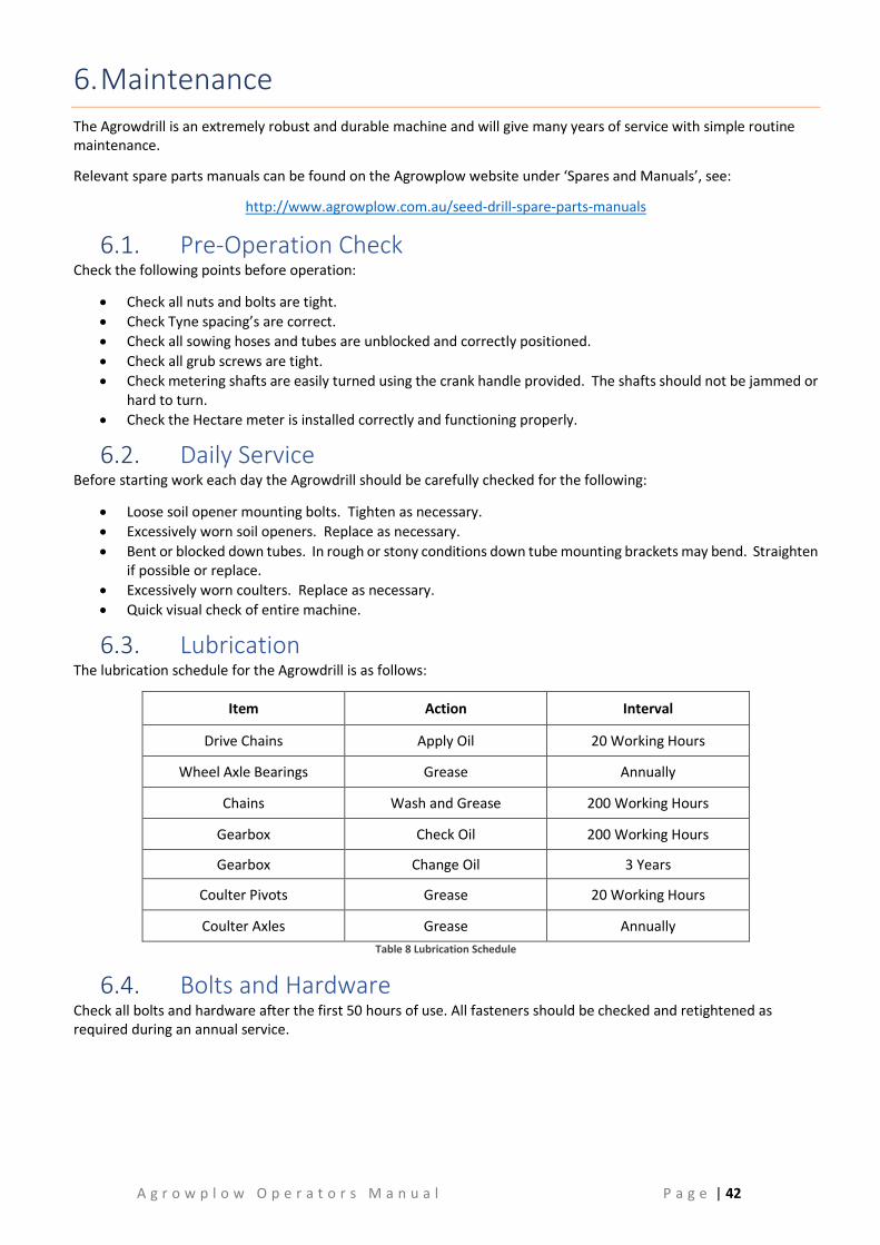
A g r o w p l o w O p e r a t o r s M a n u a l P a g e | 42
6. Maintenance
The Agrowdrill is an extremely robust and durable machine and will give many years of service with simple routine maintenance.
Relevant spare parts manuals can be found on the Agrowplow website under ‘Spares and Manuals’, see:
http://www.agrowplow.com.au/seed-drill-spare-parts-manuals
6.1. Pre-Operation Check Check the following points before operation:
• Check all nuts and bolts are tight.
• Check Tyne spacing’s are correct.
• Check all sowing hoses and tubes are unblocked and correctly positioned.
• Check all grub screws are tight.
• Check metering shafts are easily turned using the crank handle provided. The shafts should not be jammed or hard to turn.
• Check the Hectare meter is installed correctly and functioning properly.
6.2. Daily Service Before starting work each day the Agrowdrill should be carefully checked for the following:
• Loose soil opener mounting bolts. Tighten as necessary.
• Excessively worn soil openers. Replace as necessary.
• Bent or blocked down tubes. In rough or stony conditions down tube mounting brackets may bend. Straighten if possible or replace.
• Excessively worn coulters. Replace as necessary.
• Quick visual check of entire machine.
6.3. Lubrication The lubrication schedule for the Agrowdrill is as follows:
Item Action Interval
Drive Chains Apply Oil 20 Working Hours
Wheel Axle Bearings Grease Annually
Chains Wash and Grease 200 Working Hours
Gearbox Check Oil 200 Working Hours
Gearbox Change Oil 3 Years
Coulter Pivots Grease 20 Working Hours
Coulter Axles Grease Annually
Table 8 Lubrication Schedule
6.4. Bolts and Hardware Check all bolts and hardware after the first 50 hours of use. All fasteners should be checked and retightened as required during an annual service.

A g r o w p l o w O p e r a t o r s M a n u a l P a g e | 43
6.4.1. Wheel Nut Torque Chart Stud Thread Size Wheel Nut Torque - Nm (lb ft)
M10 75 (55)
M12 (and ½” UNF) 130 (97)
M14 205 (151)
M16 315 (232)
M18 435 (321)
M20 620 (457)
M22 840 (620)
M24 1070 (798) Table 9 Wheel Nut Torque Chart
Agrowplow does not warrant faults relating to wheel nut tightness. It is the responsibility of the operator to check and maintain wheel nut torque on a regular basis.
6.4.2. Standard Torque Chart Thread
Size Torque (Nm)
Grade 4.6 Grade 8.8 Grade 10.9
M8 15 28 40
M10 29 55 80
M12 50 95 140
M16 125 240 350 M18 175 330 475
M20 240 475 675
M22 330 650 925
M24 425 825 1150
M27 625 1200 1700
M30 850 1650 2300 Table 10 Standard Torque Chart
Unless otherwise specified, Grade 8.8 is the common standard for all hardware on the machine. Crimped nutserts are to be tightened to only 50% of the specified torque value.
Bolts should only be replaced with equal or higher grade bolts. If replaced by a higher grade bolt then the original bolt torque should be applied.
6.5. Replacing Soil Openers You should replace soil openers when they wear past the tungsten tip or lose their point. Blunt tips or worn heels will reduce the digging efficiency and seed placement accuracy of the Agrowdrill.
The procedure for changing soil openers is as follows:
1. Place the Agrowdrill on a hard surface and lift to the highest position and secure using the ram safety stoppers. 2. Turn the tractor off. 3. Remove retaining bolts that attach the opener to the shank. Depending on the type of opener there may be
one or two bolts. 4. Remove worn opener and any damaged bolts. 5. Install new openers and any bolts and tighten bolts firmly.
6.6. Coulter Replacement Coulter replacement procedure is as follows:
1. Place the Agrowdrill on a hard surface. Lift to the highest position and secure using the ram safety stoppers. 2. Turn the tractor off. 3. Remove retaining bolts. 4. Replace worn coulters. 5. Replace and tighten retaining bolts.

A g r o w p l o w O p e r a t o r s M a n u a l P a g e | 44
6.7. Downtube Assembly Use the following procedure to service the down tube assembly:
1. Remove the rubber boot from the retaining lugs on the fluted roller housing. 2. Twist the bottom of the flexible tube off the seeding boot and remove the downtube assembly. 3. Screw out the flexible tube. 4. Replace the rubber boot or flexible tube as required. Ensure the new flexible hose is of similar length.
6.8. Replacing Adjustable Gates The adjustable gates are controlled by a hexagonal rod connected to the adjustment lever. Use the following procedure to replace worn or broken gates:
1. Remove the drive chain cover plate from the left side of the hopper. 2. Loosen the bolt that retains the gate adjustment lever. 3. Slide the hexagonal shaft out and remove worn or broken gates as required. 4. Slide the shaft back in assembling and replacing the gates as necessary. 5. Tighten the bolt that retains the gate adjustment lever. 6. Replace the drive chain cover plate.
6.9. Servicing the Fluted Rollers The fluted rollers are driven by hexagonal shafts through the drive chains and sprockets on the left side of the Agrowdrill. These shafts are supported by self-aligning ball bearings adjacent to the sprockets and by glass filled nylon bushes mounted between every third outlet.
6.9.1. Drive Sprocket Bearings 1. Remove the drive chain cover and drive chain. 2. Remove the grub screws that retain the drive sprocket and slide the sprocket off the end of the shaft. 3. Loosen the grub screw retaining the bearing locking collar and rotate the collar to release the bearing. 4. Remove the two retaining bolts from the bearing housing and slide the bearing off the end of the shaft. 5. Replace the bearing and reinstall, reversing the above procedure.
6.9.2. Fluted Rollers 1. Remove the drive chain cover and drive chain. 2. Remove the two mounting bolts from the self-aligning bearing. 3. Pull the drive shaft out. In most cases it won’t be necessary to remove the shaft completely. Only slide the
hexagonal shaft far enough to reach the worn or damaged rollers. 4. Replace rollers as necessary and reverse the above procedure to reassemble.
6.9.3. Drive Shaft Mounting Bushes The Agrowdrill is fitted with glass filled nylon bushes between every third row. These bushes require no lubrication, are extremely wear resistant and should last the life of the machine.
Use the following procedure if service is needed:
1. Remove the fluted roller shaft as outlined in the above section. 2. Remove the retaining bolt from the worn or damaged bush and replace the bush. 3. Reinstall the drive shaft.
Figure 25 Drive shaft mounting bushes

A g r o w p l o w O p e r a t o r s M a n u a l P a g e | 45
6.10. Major Servicing of the Metering Mechanism In the event of the metering mechanism requiring major servicing the bottom of the hoppers can be completely removed.
1. Remove the down tube assemblies and fluted roller drive sprockets and bearing assembly as outlined in previous sections.
2. Remove all restrictors.
Figure 26 Removing and installing restrictors
3. Remove the retaining bolt from the front and rear of each fluted roller assembly and lower the entire metering mechanism from the bottom of the hoppers.
4. Installation procedure is the reverse of the above. The ends of the metering assembly will need to be resealed with a quality silicone sealant.
6.11. Servicing the Gearboxes The Agrowdrill gearbox requires no maintenance apart from an annual oil level check and an oil change every three years. Engine oil or any light gear oil should be adequate, engine oil 5W / 30 is suggested.
Figure 27 Gearbox oil level and filler plugs
6.12. Drive Chain Adjustments Chain tensioners are provided in the drive wheel arm, the chain to the gearbox and the chains to the metering mechanism. All chains should be adjusted until there is between 5mm and 10mm deflection of the chain with a light hand pressure applied. The longer the chain the greater the chain deflection that is allowed.
All drive chains are fitted with nylon tensioners. The procedure to adjust for chain wear is as follows:
1. Loosen the retaining bolt in the tensioner. 2. Move the tensioner up or down until the desired chain tension is achieved. 3. Retighten retaining bolt. 4. If the chain tension is still insufficient a link may need to be added or removed from the chain.

A g r o w p l o w O p e r a t o r s M a n u a l P a g e | 46
6.13. Drive Chain Maintenance The drive chains will benefit from some form of lubrication. The two recommended methods are:
• Oil chains regularly during seeding using a quality chain oil.
• Remove the drive chains annually and store them in a pot of quality chain oil.
Note: The most crucial measure to ensure long chain life is to avoid leaving the Agrowdrill exposed to the weather between seeding jobs.
6.14. End of Season Storage To ensure a long and trouble free working life please take the following steps when storing the Agrowdrill for long periods.
• Clean out the hoppers thoroughly according to the procedure outlined in section 5.5.
• Shed the Agrowdrill for protection against the weather.
• Ensure chains are properly oiled and covered before storage or remove chains and store them in an oil bath.

A g r o w p l o w O p e r a t o r s M a n u a l P a g e | 47
7. Troubleshooting Guide
7.1. Undercarriage The Problem Possible Cause Possible Solution
Poor penetration
Soil is too dry Wait for rain or irrigate
Worn soil openers Replace soil openers
Insufficient weight
Keep hoppers full
Fill tyres with water
Remove coulters
Machine not level Adjust levelling tube to suit
High soil opener wear
Soil is too dry Wait for rain or irrigate
Highly abrasive soil Use tungsten tipped points
Machine not level Adjust levelling tube to suit
Tynes ‘laying back’
The soil is too dry and hard Wait for rain or irrigate
Machine not level Adjust levelling tube to suit
Working too fast Slow to a suitable speed
Too much surface disturbance
Not working deep enough Adjust deeper
Working too fast Slow to a suitable speed
Coulters not cutting cleanly Sharpen the existing coulters
Fit new coulters
Tyne not aligned with coulter
Move tyne to align with coulter
Too deep on one side
Incorrect depth setting Adjust depth stoppers evenly
Uneven wheel pressure Inflate to recommended pressures
Low tractor tyre pressure Inflate as recommended in tractor manual
Coulter ‘bulldozing’ soil Coulter worn out Replace coulter
Seized bearing Replace coulter bearing
Coulter not penetrating Soil to hard Wait for rain or irrigate
Machine blocking up with trash
Too much trash
Graze heavily before seeding
Slash paddock
Control weeds before seeding
Fit Coulters
Wet Conditions Allow soil and trash to dry
Coulters not cutting properly Sharpen or fit new or fluted coulters
Tynes too close Adjust spacing to wider setting
Misalignment of tynes Adjust tyne spacing to correct alignment
Replace any bent or twisted tynes
Blocked downtubes or seeding boots
Mud build up Clean blockage, wait for drier conditions
Insect or rodent nests Remove downtube and clean
Prevent mice or insect infestations
Kinked downtube
Repair or replace
Avoid conditions where tubes may be damaged
Table 11 Troubleshooting Guide for Undercarriage
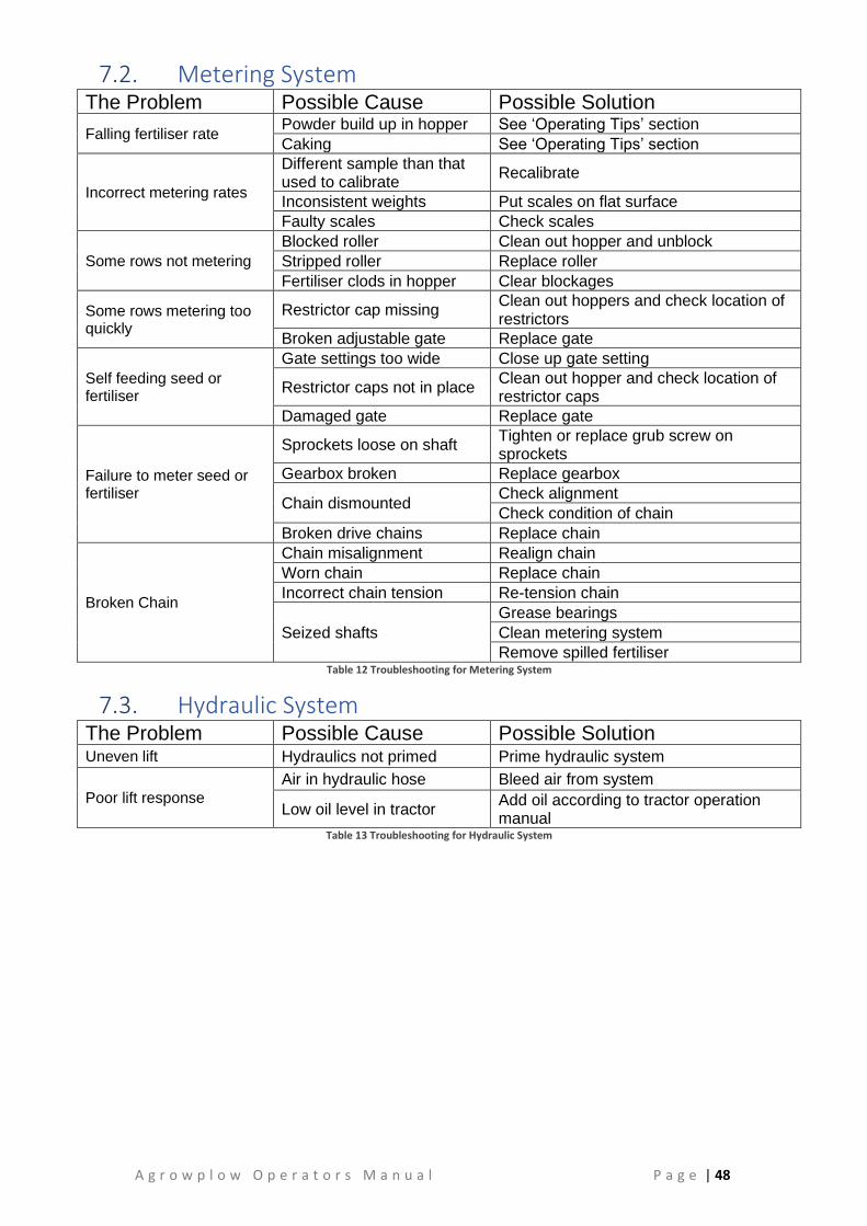
A g r o w p l o w O p e r a t o r s M a n u a l P a g e | 48
7.2. Metering System The Problem Possible Cause Possible Solution
Falling fertiliser rate Powder build up in hopper See ‘Operating Tips’ section
Caking See ‘Operating Tips’ section
Incorrect metering rates
Different sample than that used to calibrate
Recalibrate
Inconsistent weights Put scales on flat surface
Faulty scales Check scales
Some rows not metering
Blocked roller Clean out hopper and unblock
Stripped roller Replace roller
Fertiliser clods in hopper Clear blockages
Some rows metering too quickly
Restrictor cap missing Clean out hoppers and check location of restrictors
Broken adjustable gate Replace gate
Self feeding seed or fertiliser
Gate settings too wide Close up gate setting
Restrictor caps not in place Clean out hopper and check location of restrictor caps
Damaged gate Replace gate
Failure to meter seed or fertiliser
Sprockets loose on shaft Tighten or replace grub screw on sprockets
Gearbox broken Replace gearbox
Chain dismounted Check alignment
Check condition of chain
Broken drive chains Replace chain
Broken Chain
Chain misalignment Realign chain
Worn chain Replace chain
Incorrect chain tension Re-tension chain
Seized shafts
Grease bearings
Clean metering system
Remove spilled fertiliser Table 12 Troubleshooting for Metering System
7.3. Hydraulic System The Problem Possible Cause Possible Solution Uneven lift Hydraulics not primed Prime hydraulic system
Poor lift response
Air in hydraulic hose Bleed air from system
Low oil level in tractor Add oil according to tractor operation manual
Table 13 Troubleshooting for Hydraulic System

A g r o w p l o w O p e r a t o r s M a n u a l P a g e | 49
7.4. Farmscan Jackal Hectaremeter The Problem Probable Cause / Remedy
No response from ON/OFF switch
Check that power cable connections at battery are clean and tight
Measure voltage from power cable at monitor connection point. It should be between 12 – 13.8 V DC
If voltage ok and unit fails, return to nearest Farmscan dealer or authorised service agent.
Hectaremeter total wrong
Check that calibration factors H1 and H2 are correct
Is the machine overlapping or underlapping?
Is the unit counting headlands?
Switch to SPEED readout and make sure it is reading at a constant speed. Cable or sensor could be damaged if readout is jumpy.
Is the magnet facing the sensor end to end?
Is the correct magnet being used?
Is the magnet too far away from the sensor? (3-5mm gap)
Is the magnet staying in line with the sensor on corners?
Is the wheel loose?
Is the sensor on a non-driven wheel? Tractor drive wheels will cause an over reading.
Replace wheel / shaft sensor if none of the above.
Decimal point will not flash
This is normal if TOTAL hectares are above 999.9, or it is extremely cold.
Hectare or Speed does not work
Speed must be above 2.0km/h to register.
Check that the calibration factors H1 and H2 are correct.
Check that gap between magnet and sensor is 3 - 5mm
Trip or Total Hectares fail to reset
Press TOTAL or TRIP key first to select area to be cleared.
RESET key must be pressed and held down for at least 3 - 4 seconds
If hectares still fail to reset, return unit to nearest Farmscan dealer or authorised service agent.
Hectares count up on their own without moving
Switch off all other electronics to eliminate electrical interference as the cause.
If switching off other electronics eliminates the fault, ensure the Hectaremeter cables are not running alongside wiring from other electrical devices, and / or physically move the Hectaremeter in relation to the other equipment.
If petrol engine in close proximity, stop the engine to see if interference is caused by ignition system.
or Note: Carbon ignition leads must be fitted to spark plugs and coil to stop interference.
Calibration figures keep changing
Disconnect Sensor from cable at wheel / shaft. If the problem stops, replace the sensor.
Make sure the Hectaremeter has an independent power cable, wired directly to the battery + and – terminals.
If unit still counts hectares, return unit to nearest Farmscan dealer or authorised service agent.
Table 14 Troubleshooting for Farmscan Jackal Hectaremeter

A g r o w p l o w O p e r a t o r s M a n u a l P a g e | 50
8. Specifications
8.1. AD083 Series Agrowdrill Specifications Model AD083
Number of Sowing Rows
10 11 17 18
Tyne Spacing 175mm 159mm 159mm 150mm
Working Width 1.75m 2.7m
Transport Width 2.0m 2.95m
Hopper Capacity 245L 407L
Wheel Equipment 235/80 R15
Number of Toolbars 3
Toolbar Spacing 450mm
Undercarriage 425 Coil Tyne with
Baker Boot Double Disc Unit Double Disc Unit
425 Coil Tyne with Baker Boot
Drawbar Power (hp) 60-80 80-100
Linkage Type 3pt Link, CAT2 (adjustable, not quick hitch)
Frame Features Fully Welded Frame, RHS 100 x 100 x 6mm Toolbars
Hopper Features Single box, Metering System, Powder Coated, 38mm Seed Cups and Hose, Calibration Tray
Optional Equipment Spring Harrows, Rear Tow, Acre Meter Table 15 AD130 Series Agrowdrill
8.2. AD130 Series Agrowdrill Specifications Model AD130
Number of Sowing Rows 12 16 20
Tyne Spacing 150mm 150mm 150mm
Working Width 1.8m 2.4m 3.0m
Transport Width 2.29m 2.89m 3.49m
Hopper Capacity Front: 215L / Rear: 215L Front: 300L / Rear: 300L Front: 385L / Rear: 385L
Wheel Equipment 235 / 75 R15 AT Wheels
Number of Toolbars 3
Toolbar Spacing 440mm
Undercarriage 425 Coil Tyne with Baker Boot
Double Disc Unit Drawbar Power (hp) 60 – 80 70 – 90 80-100
Linkage Type Trailing with Hydraulic Lift
3pt Link, CAT2 (adjustable, not quick hitch)
Frame Features Fully Welded Frame
RHS 100 x 100 x 6mm Toolbars
Hopper Features Dual Compartments, Twin Distributor Metering System,
Powder Coated, 38mm Seed Cups and Hose, Calibration Tray
Optional Equipment Spring Release Coulter Gang, Spring Harrows
Rear Tow with option for Hydraulic Couplings, Small Seed Box Table 16 AD130 Series Agrowdrill

A g r o w p l o w O p e r a t o r s M a n u a l P a g e | 51
8.3. AD230 Series Agrowdrill Specifications Model AD230 Number of Sowing Rows 20 24 24 28 Tyne Spacing 150 125 150 125 Working Width 3.0m 3.0m 3.6m 3.5m Hopper Capacity 605L / 605L 710L / 710L Wheels 11.5/80-15.5 Implement Tyres Transport Width 3.25m 3.7m
Number of Toolbars 4 Toolbar Spacing 422mm (17”) Undercarriage 425 Coil Tyne with Baker Boot
Drawbar Power 80 – 100 100 – 130
Linkage Type Trailing Safety Features Wide Platform, Full Length Hand Rail Chain Guards Frame Features RHS 100 x 100 x 6mm Toolbars
Fully Welded Frame Calibration Tray Mounted Toolbox
Hopper Features Dual Compartments
Individual Lids Powder Coated
Twin Distributor Metering System 38mm (1 1/2”) Seed Cups and Hose
Options Double Shooting
Rear Tow Hitch Hydraulics for Rear Tow Hitch Small Seeds Box
Press wheels Harrows
Table 17 AD230 Series Agrowdrill
8.1. AD730 Series Agrowdrill Specifications Model AD730 Number of Sowing Rows 18 22 20 24 28 Tyne Spacing 225mm 175mm Working Width 4.05m 4.95m 3.50m 4.20m 4.90m Hopper Capacity 880L/880L 1080L/1083L 755L/755L 920L/920L 1080L/1083L Wheels 380/85 R24 Transport Width 4.87m 5.75m 4.35m 5.05m 5.75m
Number of Toolbars 4 Toolbar Spacing 550mm
Undercarriage HD Spring Tyne / Spring Tyne / Disc Assembly
Drawbar Power 120-150 130-180 120-150 130-160 150-200
Linkage Type Trailing
Safety Features Wide Platform, Full Length Hand Rail
Chain Guards Hydraulic Level Lift Hitch
Frame Features RHS 100 x 100 x 6mm Toolbars
Fully Welded Frame Calibration Tray
Mounted Toolbox
Hopper Features Dual Compartments
Individual Lids Powder Coated
Twin Distributor Metering System 38mm (1 1/2”) Seed Cups and Hose
Options Double Shooting
Rear Tow Hitch Small seed flexi chutes
Small Seeds Box Press wheels
Harrows Table 18 AD730 Series Agrowdrill

A g r o w p l o w O p e r a t o r s M a n u a l P a g e | 52
9. Warranty
9.1. Warranty Policy Agrowplow warrants to its Dealer, who in turn warrants to the purchaser, that each new product, part or accessory will be free from defects in material and workmanship for 3 years after delivery and installation by an Agrowplow Dealer, according to the conditions outlined.
This warranty is in lieu of all other warranties (except those of title), expressed or implied, and there are no warranties of fitness for the particular purpose. In no event shall Agrowplow be liable for downtime expenses, loss of machine use, loss of crops, loss of profits, injury or damage arising from accident, direct or indirect loss, or other incidental, consequential or special damages.
The Safe Use Inspection (SUI) and Pre Delivery Inspection (PDI) Forms must be filled in and returned to Agrowplow by the Dealer or Agrowplow representative within seven days of delivery and installation of the unit. By signing the SUI & PDI Forms, the owner acknowledges that he is responsible for the safe operation of the product, and that he undertakes to fully train any person that might operate the product.
9.2. Conditions of Warranty In the event of a defect which may result in a warranty claim:
• The Owner must provide the Authorised Dealer with written notice of the defect within 14 days of its occurrence, and allow reasonable time for replacement or repair.
• At Agrowplow’s request the Dealer will ensure any failed parts are freighted to the Agrowplow factory. Transportation of the Agrowplow product to the Authorised Servicing Dealer for warranty work is the responsibility of the Owner.
• The Warranty is not transferable to any third party or subsequent purchaser.
• Components and conditions not covered by warranty include:
Abuse Failure resulting from neglect, improper operation, lack of required maintenance or continued use of machine after the discovery of a defect which results in greater damage to the unit.
Environmental Conditions and Application Deteriorated or failed components such as hydraulic hoses, seals, valves or connections damaged by corrosive materials, dirt, sand, excessive heat or moisture. Warranty determination for these types of failures will be made by Agrowplow only after inspection of failed components.
Normal Wear Normal wear and consumable items such as oils and lubricants, nuts, bolts, washers, grease caps, spanners, jacks, bearing housings, axles, poppet valves or seal kits for hydraulic cylinders, seals, points, discs, axles, tyres, machine adjustment and periodic service. These are considered to be normal wear items and are not warranted.
Maintenance Component failure caused by non-performance of scheduled maintenance such as correct lubrication and maintenance, tightening or replacement of bolts, nuts, fittings, shields and covers.
Damage Damage or machine failure caused by carelessness, accidents, improper operation, inappropriate transportation or storage of the machine, parts or attachments.
Alterations Any unauthorised alteration, modification, attachments or unauthorised repairs to the Agrowplow product, parts or attachments. Written approval must be obtained from Agrowplow for any such items to maintain warranty.

A g r o w p l o w O p e r a t o r s M a n u a l P a g e | 53
Replacement Parts & Service Work The Labour or expenses involved in any of the following replacements or service tasks is the responsibility of the owner:
• Replacement of faulty tynes
• Soil opener replacement
• Metering roller adjustment or replacement
• Any bearing replacement
• Adjustments (refer to manual)
• Drive shaft adjustment or replacement
• Periodic service work.
Agrowplow and its Dealers are not responsible or liable for any such expenses.
Clean-up Time Agrowplow does not pay for cleaning the products, parts, accessories or work area before or after the warranty repair. Clean-up time is affected primarily by the application or conditions in which the unit is operated and maintained. Since clean-up time can be so variable, cleaning time should be considered a customer expense.
Transportation & Insurance Costs Warranty does not cover transportation or insurance costs for its products or other equipment needing repair or replacement of warranted components.
Travel Time Travel time required for warranty repairs is the responsibility of the Owner. In the event of a recall for faulty parts, warranty repairs will be covered.
Diagnostic Time Warranty does not cover time required to diagnose a warranty problem. Diagnostic time is affected greatly by the training and expertise of the technician employed to do the job. With proper training of service personnel, diagnostic time should be at a minimum. Agrowplow expects that Dealers will assign a well-trained and proficient technician to handle warranty repairs. Diagnostic time is considered a dealer expense.
Non – Genuine Parts Use of parts other than Agrowplow parts for repair of warranted parts will automatically negate any warranty. Warranted components must be replaced with genuine Agrowplow repair parts by an authorized Agrowplow representative.
Unauthorised Repairs Repairs by an unauthorised agent will automatically forfeit any warranty. Warranty repairs must be carried out by an Authorised Agrowplow Dealer only, and only after Agrowplow’s authorisation has been obtained.
Special Warranty Considerations apply in respect to the following: Tyres, Hydraulics and Castings:
These items are covered by their respective manufacturer’s warranty. For example many tyre manufactures will only warrant tyres pro rata. Claims for faults relating to these components must follow Agrowplow’s normal claim procedures.


![TAURUS CULTIVATOR / SEED DRILL...3 TAURUS CULTIVATOR / SEED DRILL Width [m] 2.5 2.7 3.0 4.0 Weight [kg] 1100 1220 1360 1840 Number of discs / hubs 20 22 24 32 Power demand [HP] 60÷90](https://static.fdocuments.net/doc/165x107/5fdf74b7c012e116fb47b4e6/taurus-cultivator-seed-drill-3-taurus-cultivator-seed-drill-width-m-25.jpg)