SEE VICTAULIC PUBLICATION 10.01 FOR DETAILS STYLE 177 Lenntech 177.pdf · standard roll grooved and...
4
SEE VICTAULIC PUBLICATION 10.01 FOR DETAILS The Style 177 QuickVic flexible coupling is installation-ready, and joins 2-8"/50-200 mm standard roll grooved and cut grooved steel pipe. The coupling's unique design eliminates loose parts, ensures consistent installation and provides substantial gains in productivity. The Style 177 flexible coupling can accommodate pressures ranging from full vacuum (29.9 in Hg/760 mm Hg) up to 1000 psi/6900 kPa. The coupling's maximum pressure rating will depend on the diameter and wall thickness of the pipe. * Sizes 2-4"/50-100 mm may be used to join 304/304L and 316/316L Schedule 10 stainless steel pipe from full vacuum (29.9 in Hg/760 mm Hg) to a maximum rated working pressure of 300 psi/2065 kPa. MATERIAL SPECIFICATIONS Housing: Ductile iron conforming to ASTM A-536, grade 65-45-12. Housing Coating: Orange enamel. Optional Coatings: • Hot dipped galvanized Gasket: • Grade “EHP” EHP (Red & Green stripe color code). Temperature range –30°F to +250°F/–34°C to +121°C. Recommended for hot water service within the specified temperature range plus a variety of dilute acids, oil-free air and many chemical services.* UL classified in accordance with ANSI/NSF 61 for cold +86°F/+30°C and hot +180°F/+82°C potable water service. NOT RECOMMENDED FOR PETROLEUM SERVICES. • Grade “T” nitrile Nitrile (Orange color code). Temperature range –20°F to +180°F/–29°C to +82°C. Recommended for petroleum products, air with oil vapors, vegetable and mineral oils within the specified temperature range. Not recommended for hot water services over +150°F/+66°C or for hot dry air over +140°F/+60°C. * Services listed are General Service Recommendations only. It should be noted that there are services for which these gaskets are not recommended. Reference should always be made to the latest Victaulic Gasket Selection Guide for specific gasket service recommendations and for a listing of services which are not recommended. Bolts/Nuts: Heat-treated plated carbon steel, trackhead meeting the physical and chemical requirements of ASTM A-449 and physical requirements of ASTM A-183. Optional Bolts/Nuts: (Available in imperial size bolts and nuts only.) Bolts: Stainless steel, meeting the requirements of ASTM F-593, Group 2 (316 stainless steel), condition CW, with galling resistant coating. Nuts: ASTM F-594, Group 2 (316 stainless steel), condition CW 06.20_1 QuickVic ® Flexible Coupling for Steel STYLE 177 06.20 CARBON STEEL PIPE – GROOVED COUPLINGS JOB/OWNER CONTRACTOR ENGINEER System No. __________________________ Submitted By ________________________ Spec Sect ____________ Para __________ Location ____________________________ Date ________________________________ Approved ___________________________ Date ________________________________ www.victaulic.com VICTAULIC IS A REGISTERED TRADEMARK OF VICTAULIC COMPANY. © 2011 VICTAULIC COMPANY. ALL RIGHTS RESERVED. REV_K Lenntech [email protected] www.lenntech.com Tel. +31-15-261.09.00 Fax. +31-15-261.62.89
Transcript of SEE VICTAULIC PUBLICATION 10.01 FOR DETAILS STYLE 177 Lenntech 177.pdf · standard roll grooved and...
SEE VICTAULIC PUBLICATION 10.01 FOR DETAILS
The Style 177 QuickVic flexible coupling is installation-ready, and joins 2-8"/50-200 mm standard roll grooved and cut grooved steel pipe. The coupling's unique design eliminates loose parts, ensures consistent installation and provides substantial gains in productivity. The Style 177 flexible coupling can accommodate pressures ranging from full vacuum (29.9 in Hg/760 mm Hg) up to 1000 psi/6900 kPa. The coupling's maximum pressure rating will depend on the diameter and wall thickness of the pipe.
* Sizes 2-4"/50-100 mm may be used to join 304/304L and 316/316L Schedule 10 stainless steel pipe from full vacuum (29.9 in Hg/760 mm Hg) to a maximum rated working pressure of 300 psi/2065 kPa.
MATERIAL SPECIFICATIONS Housing: Ductile iron conforming to ASTM A-536, grade 65-45-12.
Housing Coating: Orange enamel.
Optional Coatings:
• Hot dipped galvanized
Gasket:
• Grade“EHP”EHP (Red & Green stripe color code). Temperature range –30°F to +250°F/–34°C to +121°C. Recommended for hot water service within the specified temperature range plus a variety of dilute acids, oil-free air and many chemical services.* UL classified in accordance with ANSI/NSF 61 for cold +86°F/+30°C and hot +180°F/+82°C potable water service. NOT RECOMMENDED FOR PETROLEUM SERVICES.
•Grade“T”nitrile Nitrile (Orange color code). Temperature range –20°F to +180°F/–29°C to +82°C. Recommended for petroleum products, air with oil vapors, vegetable and mineral oils within the specified temperature range. Not recommended for hot water services over +150°F/+66°C or for hot dry air over +140°F/+60°C.
* Services listed are General Service Recommendations only. It should be noted that there are services for which these gaskets are not recommended. Reference should always be made to the latest Victaulic Gasket Selection Guide for specific gasket service recommendations and for a l isting of services which are not recommended.
Bolts/Nuts: Heat-treated plated carbon steel, trackhead meeting the physical and chemical requirements of ASTM A-449 and physical requirements of ASTM A-183.
Optional Bolts/Nuts: (Available in imperial size bolts and nuts only.)
Bolts: Stainless steel, meeting the requirements of ASTM F-593, Group 2 (316 stainless steel), condition CW, with galling resistant coating.
Nuts: ASTM F-594, Group 2 (316 stainless steel), condition CW
06.20_1
QuickVic®FlexibleCouplingforSteelSTYLE 177
06.20CARBON STEEL PIPE – GROOVED COUPLINGS
JOB/OWNER CONTRACTOR ENGINEER
System No. __________________________ Submitted By ________________________ Spec Sect ____________ Para __________
Location ____________________________ Date ________________________________ Approved ___________________________
Date ________________________________
www.victaulic.comVICTAULIC IS A REGISTERED TRADEMARK OF VICTAULIC COMPANY. © 2011 VICTAULIC COMPANY. ALL RIGHTS RESERVED.
REV_K
[email protected]. +31-15-261.09.00Fax. +31-15-261.62.89
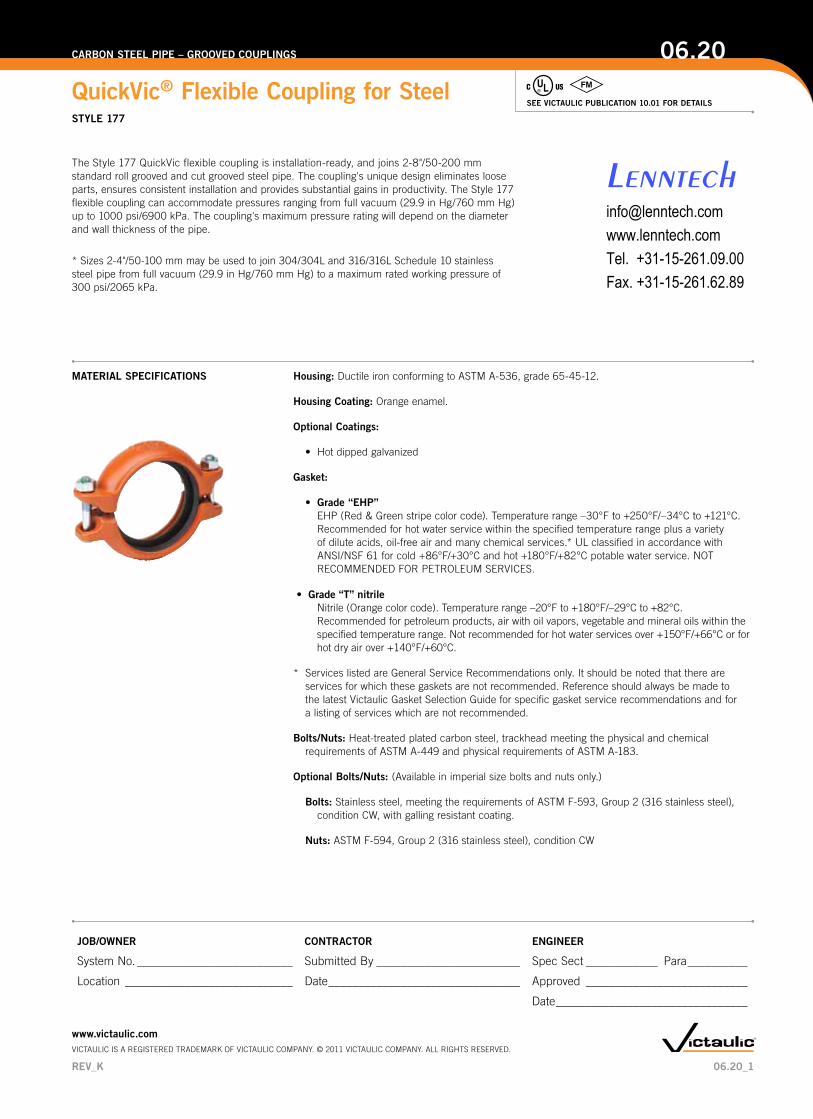
DIMENSIONS
STYLE 177 JOINT ASSEMBLED
STYLE 177 PRE-ASSEMBLED(INSTALLATION-READY CONDITION)
Size
PipeEndSep.
Inchesmm
Bolt/NutNo. – Size Dimensions – Inches/mm
Aprx.Wgt. Ea.
Nominal Size
Inchesmm
Actual OutsideDiameterInches
mm(1)Min
(2)Max
(3)Max
Inchesmm
Pre-assembled(Installation-ready
condition) JointAssembledLbs.kgX Y X Y Z
2 2.375 0.13 0.19 0.25 2 – ³⁄₈ x 2½ 3.87 5.59 3.56 5.39 2.05 2.050 60.3 3.2 4.8 6.4 98 142 90 1.37 52 0.92½ 2.875 0.13 0.19 0.25 2 – ³⁄₈ x 2½
4.36 6.13 4.05 5.89 2.05 2.465 73.0 3.2 4.8 6.4 111 156 103 150 52 1.1
76.1mm3.000 0.13 0.19 0.25 2 – M10 x 2½
4.40 6.31 4.09 6.28 2.02 2.576.1 3.2 4.8 6.4 112 160 104 160 51 1.1
3 3.500 0.13 0.19 0.25 2 – ½ x 35.00 7.05 4.68 6.81 2.04 3.1
80 88.9 3.2 4.8 6.4 127 179 119 173 52 1.44 4.500 0.13 0.25 0.38 2 – ½ x 3
5.98 8.24 5.61 7.92 2.15 3.7100 114.3 3.2 6.4 9.5 152 209 142 201 54 1.7
5 5.563 0.13 0.25 0.38 2 – ½ x 37.07 9.66 6.68 9.55 2.09 4.8
125 141.3 3.3 6.4 9.7 180 245 170 243 53 2.2
139.7mm5.500 0.13 0.25 0.38 2 – M12 x 3
7.01 9.52 6.71 9.42 2.14 4.9139.7 3.2 6.4 9.5 178 242 171 240 54 2.2
6 6.625 0.13 0.25 0.38 2 – ⁵⁄₈ x 48.27 11.14 8.00 11.12 2.18 7.4
150 168.3 3.2 6.4 9.5 210 283 203 282 55 3.48 8.625 0.19 0.31 0.44 2 – ⁵⁄₈ x 4
10.48 13.56 10.09 13.42 2.56 10.5200 219.1 4.8 7.9 11.2 266 344 256 341 65 4.7
(1) The minimum pipe end separation as required by the gasket center leg for roll or cut grooved pipe. See illustrations below.
(2 & 3) Maximum pipe end separation to be used for determining overall piping system movement for roll (2) or cut (3) groove pipe. For design and installation purposes, the minimum and maximum pipe end separations should be reduced to the values shown in the table below. These design and installation considerations include thermal growth, settlement, installation misalignment and offsets. See illustrations below.
Minimum Pipe Separation (1)Roll and Cut Groove
Maximum Pipe Separation (2)Roll Groove
Exaggerated for clarity
Maximum Pipe Separation (3)Cut Groove
The amount of linear movement and angular deflection to be used for design and installation consideration for each coupling is shown in the table below.
DESIGN AND INSTALLATION
Size RangeDesignandInstallationValues
RollGroovePipe CutGroovePipe
Inches/mm LinearMovement#
AngularDeflection†
LinearMovement#
AngularDeflection†
PerCplg.Deg.Pipe In/Ft
mm/m PerCplg.Deg.Pipe In/Ft
mm/m
2 0.06 0.32 0.13 0.6450 1.6 1.52° 26 3.2 3.04° 522½ 0.06 0.26 0.13 0.5265 1.6 1.25° 22 3.2 2.50° 44
76.1 mm0.06 0.26 0.13 0.521.6 1.20° 22 3.2 2.40° 44
3 0.06 0.22 0.13 0.4480 1.6 1.03° 18 3.2 2.06° 364 0.13 0.34 0.25 0.68
100 3.2 1.60° 28 6.4 3.20° 565 0.13 0.27 0.25 0.54
125 3.3 1.30° 22 6.4 2.60° 45
139.7 mm0.13 0.28 0.25 0.543.3 1.30° 24 6.4 2.60° 45
6 0.13 0.23 0.25 0.46150 3.2 1.08° 18 6.4 2.16° 36
8 0.13 0.18 0.25 0.35200 3.3 0.83° 15 6.4 1.66° 29
† Victaulic recommends for design and installation purposes, these values should be reduced by 50% for ¾-3 ½"/20-90 mm sizes; 25% for 4"/100 mm and larger sizes.
06.20_2
QuickVic®FlexibleCouplingforSteelSTYLE 177
06.20CARBON STEEL PIPE – GROOVED COUPLINGS
www.victaulic.comVICTAULIC IS A REGISTERED TRADEMARK OF VICTAULIC COMPANY. © 2011 VICTAULIC COMPANY. ALL RIGHTS RESERVED.
REV_K
X
Y Z
X
Y Z
X
Y Z
X
Y Z
[email protected]. +31-15-261.09.00Fax. +31-15-261.62.89
PERFORMANCE
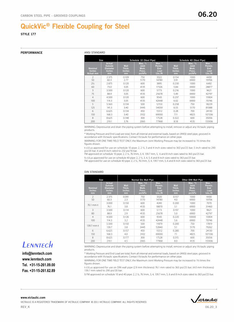
Size Schedule10(SteelPipe) Schedule40(SteelPipe)
NominalInches
Actual mm
Actual OutsideDiameterInches
mm
WallThick.Inches
mm
Max. *ŧJoint Work.Press.psi/kPa
Max. *Permis.EndLoadLbs./N
WallThick.Inches
mm
Max. *§Joint Work.Press.psi/kPa
Max. *Permis.EndLoadLbs./N
2 2.375 0.109 750 3322 0.154 1000 443050 60.3 2.77 5170 14780 3.91 6900 197062½ 2.875 0.120 600 3895 0.230 1000 649260 73.0 3.05 4135 17326 5.84 6900 288773 3.500 0.120 600 5773 0.216 1000 9621
75 88.9 3.05 4135 25678 5.49 6900 427974 4.500 0.120 600 9543 0.237 1000 15904
100 114.3 3.05 4135 42448 6.02 6900 707465 5.563 0.134 500 12153 0.258 750 18229
125 141.3 3.40 3445 54059 6.55 5170 810886 6.625 0.134 450 15512 0.28 700 24130
150 168.3 3.40 3102 69000 7.11 4825 1073368 8.625 0.148 300 17528 0.322 600 35056
200 219.1 3.76 2065 77968 8.18 4135 155936
WARNING: Depressurize and drain the piping system before attempting to install, remove or adjust any Victaulic piping products.* Working Pressure and End Load are total, from all internal and external loads, based on (ANSI) steel pipe, grooved in accordance with Victaulic specifications. Contact Victaulic for performance on other pipe.WARNING: FOR ONE TIME FIELD TEST ONLY, the Maximum Joint Working Pressure may be increased to 1½ times the figures shown. ŧ cULus approved for use on schedule 10 pipe: 2, 2 ½, 3 and 4 inch sizes rated to 363 psi/25 bar; 5 inch rated to 290 psi/20 bar; 6 and 8 inch rated to 232 psi/16 bar. FM approved on schedule 10 pipe: 2, 2 ½, 76.1mm, 3, 4, 139.7 mm, 5, 6 and 8 inch sizes rated to 363 psi/25 bar.§ cULus approved for use on schedule 40 pipe: 2, 2 ½, 3, 4, 5, 6 and 8 inch sizes rated to 363 psi/25 bar. FM approved for use on schedule 40 pipe: 2, 2 ½, 76.1mm, 3, 4, 139.7 mm, 5, 6 and 8 inch sizes rated to 363 psi/25 bar.
Size NormalDinWallPipe OtherDINWallPipe
NominalInches
mm
Actual OutsideDiameterInches
mm
WallThick.Inches
mm
Max. *ŧ§Joint Work.Press.psi/kPa
Max. *Permis.EndLoadLbs./N
WallThick.Inches
mm
Max. *§Joint Work.Press.psi/kPa
Max. *Permis.EndLoadLbs./N
2 2.375 0.091 750 3320 0.157 1000 443050 60.3 2.3 5170 14780 4.0 6900 19706
76.1 mm ŧ 3.000 0.150 600 4240 0.200 1000 707076.1 3.8 4135 18870 5.1 6900 31460
3 3.500 0.114 600 5773 0.197 1000 962180 88.9 2.9 4135 25678 5.0 6900 427974 4.500 0.126 600 9543 0.220 10000 15904
100 114.3 3.2 4135 42448 5.6 6900 70746
139.7 mm ŧ5.500 0.150 500 11879 0.200 750 17819139.7 3.8 3445 52840 5.1 5170 79262
6 6.625 0.157 450 15512 0.280 700 24130150 168.3 4.0 3102 69000 7.1 4825 107336
8 8.625 0.177 300 17528 0.315 600 35056200 219.1 4.5 2065 77968 8.0 4135 155936
WARNING: Depressurize and drain the piping system before attempting to install, remove or adjust any Victaulic piping products.* Working Pressure and End Load are total, from all internal and external loads, based on (ANSI) steel pipe, grooved in accordance with Victaulic specifications. Contact Victaulic for performance on other pipe.WARNING: FOR ONE TIME FIELD TEST ONLY, the Maximum Joint Working Pressure may be increased to 1½ times the figures shown. ŧ cULus approved for use on DIN wall pipe (2.9 mm thickness) 76.1 mm rated to 363 psi/25 bar; (4.0 mm thickness) 139.7 mm rated to 290 psi/20 bar.§ FM approved on schedule 10 and 40 pipe: 2, 2 ½, 76.1mm, 3, 4, 139.7 mm, 5, 6 and 8 inch sizes rated to 363 psi/25 bar.
ANSI STANDARD
DIN STANDARD
06.20_3
QuickVic®FlexibleCouplingforSteelSTYLE 177
06.20CARBON STEEL PIPE – GROOVED COUPLINGS
www.victaulic.comVICTAULIC IS A REGISTERED TRADEMARK OF VICTAULIC COMPANY. © 2011 VICTAULIC COMPANY. ALL RIGHTS RESERVED.
REV_K
[email protected]. +31-15-261.09.00Fax. +31-15-261.62.89

WARRANTY Refer to the Warranty section of the current Price List or contact Victaulic for details.
This product shall be manufactured by Victaulic or to Victaulic specifications. All products to be installed in accordance with current Victaulic installation/assembly instructions. Victaulic reserves the right to change product specifications, designs and standard equipment without notice and without incurring obligations.
NOTE
Reference should always be made to the I-177 Victaulic Field Installation Instructions for the product you are installing. Instructions are included with each shipment of Victaulic products for complete installation and assembly data, and are available in PDF format on our website at www.victaulic.com.
INSTALLATION
GENERAL NOTES NOTE: When assembling Style 177 QuickVic flexible couplings onto end caps, take additional care to make certain the end cap is fully seat against the gasket center leg. For Style 177 QuickVic flexible couplings, use Victaulic No. 60 end caps containing "QV" or "QV/EZ" markings on the inside of the face. Non-Victaulic fittings shall not be used with Style 177 QuickVic flexible couplings.
06.20
QuickVic®FlexibleCouplingforSteelSTYLE 177
06.20CARBON STEEL PIPE – GROOVED COUPLINGS
06.205147REVKUPDATED10/2011VICTAULIC IS A REGISTERED TRADEMARK OF VICTAULIC COMPANY. © 2011 VICTAULIC COMPANY. ALL RIGHTS RESERVED.
[email protected]. +31-15-261.09.00Fax. +31-15-261.62.89