
SED2 VFD NEMA Type 3R Bypass VFD NEMA Type 3R Bypass Operating Instructions 2 Siemens Building...
62
Item Number 125-3377, Rev. 030 SED2 VFD NEMA Type 3R Bypass Operating Instructions
Transcript of SED2 VFD NEMA Type 3R Bypass VFD NEMA Type 3R Bypass Operating Instructions 2 Siemens Building...
Item Number 125-3377, Rev. 030
SED2 VFD NEMA Type 3R Bypass
Operating Instructions


SED2 VFD NEMA Type 3R Bypass Operating Instructions

NOTICE
The information contained within this document is subject to change without notice and should not be construed as a commitment by Siemens Building Technologies, Inc. Siemens Building Technologies, Inc. assumes no responsibility for any errors that may appear in this document.
All software described in this document is furnished under a license and may be used or copied only in accordance with the terms of such license.
WARNING
The Siemens Building Technologies SED2 Variable Frequency Drives are shipped without EMC line filters. (The EMC filter is most commonly used in Europe.) Where local codes or customer/installation requirements dictate, separately orderable Class A line filters are available. More stringent Class B line filters are also available for most models. Installation of these filters satisfies the requirements for the EU's EMC directive.
SERVICE STATEMENT
Control devices are combined to make a system. Each control device is mechanical in nature and all mechanical components must be regularly serviced to optimize their operation. All Siemens Building Technologies, Inc. branch offices and authorized distributors offer Technical Support Programs that will ensure your continuous, trouble-free system performance.
For further information, contact your nearest Siemens Building Technologies, Inc. representative.
CREDITS
Product or company names mentioned herein may be the trademarks of their respective owners.
Copyright © 2004 by Siemens Building Technologies, Inc.
TO THE READER
Your feedback is important to us. If you have comments about this manual, please submit them to [email protected].
Country of Origin: US

Table of Contents
Siemens Building Technologies, Inc. i
Table of Contents
How to Use this Manual................................................................................................ 1
Manual Organization.................................................................................................. 1 Manual Notations ....................................................................................................... 1 Where To Send Comments ....................................................................................... 1 Reference Documents ............................................................................................... 2
Safety Instructions........................................................................................................ 3
SED2 VFD NEMA Type 3R Bypass Overview............................................................. 4
NEMA Type 3R Bypass Operation Overview ............................................................. 6
Installation ..................................................................................................................... 8
Environmental Conditions.......................................................................................... 8 Inspection................................................................................................................... 8 Dimensions and Weights ........................................................................................... 9 Mounting .................................................................................................................... 10 Wiring Connections.................................................................................................... 12 Motor Cable Length ................................................................................................... 18 Access to SED2 Connection Terminals..................................................................... 19
Startup Procedures....................................................................................................... 26
Preparation ................................................................................................................ 26 Start-up ...................................................................................................................... 27 Quick Commissioning Procedure .............................................................................. 31 Additional Parameter Settings ................................................................................... 41
Flying Start .............................................................................................................. 41 Automatic Restart.................................................................................................... 43 Vdc Controller.......................................................................................................... 45 Pulse Frequency ..................................................................................................... 46 Reset to Factory Defaults........................................................................................ 47
Required SED2 Parameter Settings .......................................................................... 48
Technical Specifications .............................................................................................. 49
Troubleshooting............................................................................................................ 51
Fuses ......................................................................................................................... 52


How to Use this Manual
Siemens Building Technologies, Inc. 1
How to Use this Manual
Manual Organization
This manual contains the following sections:
• How to Use this Manual describes the organization of this manual and the symbols used throughout this manual.
• Safety Instructions provides general guidelines for your safety and to prevent equipment damage.
• SED2 VFD NEMA Type 3R Bypass Overview describes the function and components.
• Operation Overview describes the operating modes of the NEMA Type 3R Bypass.
• Installation provides mounting information and details on electrical connections.
• Startup Procedures provides step-by-step procedures to start up the NEMA Type 3R Bypass.
• Technical Specifications lists NEMA Type 3R Bypass specification data.
• Troubleshooting provides guidelines for troubleshooting the NEMA Type 3R Bypass.
Manual Notations Notation Symbol Meaning
WARNING:
Indicates that personal injury/loss or life may occur if you do not perform a procedure as specified.
CAUTION:
Indicates that equipment damage or loss of data may occur if you do not perform a procedure as specified.
NOTES: (No symbol) Provides other important information or helpful hints.
Where To Send Comments Your feedback is important to us. If you have comments about this manual, please submit them to [email protected].

SED2 VFD NEMA Type 3R Bypass Operating Instructions
2 Siemens Building Technologies, Inc.
Reference Documents The following SED2 VFD documentation is available from your local Siemens Building Technologies representative:
• SED2 VFD Startup, Operation & Maintenance Manual (125-3201)
• SED2 VFD Parameter Reference Guide (125-3214)
• SED2 Variable Frequency Drives Submittal Sheet (154-042)
• SED2 VFD NEMA Type 3R Bypass Submittal Sheet (154-062)
• SED2 VFD Conventional Bypass Option Submittal Sheet (154-044)

Safety Instructions
Siemens Building Technologies, Inc. 3
Safety Instructions The following general guidelines are provided for your safety, to prevent damage, and to extend the service life of the SED2 product and any connected equipment. Read this information carefully. Specific Warnings, Cautions, and Notes are provided in the relevant sections of this manual.
WARNINGS:
• The SED2 uses hazardous voltages and controls potentially dangerous rotating mechanical parts. Non-compliance with warnings or failure to follow the instructions contained in this manual can result in loss of life, severe personal injury, or serious damage to property/equipment.
• Only authorized personnel should work on this equipment, and only after becoming familiar with all local regulations and ordinances; safety notices; and installation, operation, and maintenance procedures in this manual. Successful and safe operation of this equipment depends upon its proper handling, installation, operation, and maintenance.
• Before carrying out any installation and commissioning procedures, you must read all safety instructions and warnings, including all warning labels attached to the equipment. Make sure that the warning labels are kept in a legible condition and ensure missing or damaged labels are replaced.
• Observe the regulations of Safety Code VBG 4.0 (in particular, “Permissible Deviations when Working with Live Parts”) whenever measuring or testing is performed on live equipment. Also, use suitable NEMA Type 3R Bypass and SED2 tools.
• Use this equipment for only the purpose specified by the manufacturer. Unauthorized modifications and the use of spare parts and accessories that are not sold or recommended by the manufacturer of the equipment can cause fires, electric shocks, and injuries.
• Prevent the general public from accessing or approaching this equipment.
NOTE: Keep these Operating Instructions near the equipment and available to all users.

SED2 VFD NEMA Type 3R Bypass Operating Instructions
4 Siemens Building Technologies, Inc.
SED2 VFD NEMA Type 3R Bypass Overview
During normal operation of a NEMA Type 3R Bypass in a typical application, the input and output contactors close and the SED2 operates the motor (Figure 1). The bypass contactor provides the ability to operate the motor on utility power and eliminate the SED2 from the motor control circuit.
Drive
Motor
2 Contactor Bypass
InputDevice
Drive
Motor
3 Contactor Bypass
InputDevice
VF
D00
08R
1
Figure 1. Functional Diagram of Typical NEMA Type 3R Bypass.
The NEMA Type 3R Bypass consists of a SED2, NEMA Type 3R bypass enclosure, and controls. NEMA Type 3R Bypass components (Figure 2 and 4) include:
• Control terminal block
• "Drive-Off-Bypass" switch
• "Bypass On" light
• "Drive Test On-Off" switch (optional)
• Control Transformer
• Power fuses
• Relays
• Overload (current) relay
• Bypass Contactor
• Output Contactor
• Input Contactor (optional)
• Motor Contactor
• Disconnect switch
• Heater

SED2 VFD NEMA Type 3R Bypass Overview
Siemens Building Technologies, Inc. 5
BYPASS CONTACTOR
DISCONNECT SWITCH
GROUND LUGS
MOTOR OVERLOADBAFFLE
GROMMETS
HEATER
SED2 VFDFRAME SIZE C
INPUT CONTACTOR
CONTROL TERMINAL BLOCK
OUTPUT CONTACTOR
LINE REACTOR
RELAYS
CONTROL TRANSFORMER
POWER FUSES
SED2 VFDFRAME SIZE E
CONTROL TERMINAL BLOCK
BYPASS CONTACTOR
DISCONNECT SWITCH
GROUND LUGS
MOTOR OVERLOAD
CONTROL TRANSFORMERINPUT CONTACTOR
BAFFLE
GROMMETS
HEATER
LINE REACTOR
RELAYS
POWER FUSES
OUTPUT CONTACTOR
Enclosure ABC. Enclosure DE.
SED2 VFDFRAME SIZE F
INPUT CONTACTOR
BAFFLE
GROMMETS
HEATER
TERMINAL BLOCK
DISCONNECT SWITCH
GROUND LUGS
MOTOR OVERLOAD
OUTPUT CONTACTOR
BYPASS CONTACTOR
LINE REACTOR
CONTROL TRANSFORMER POWER FUSES
RELAYS
Enclosure F.
Figure 2. Typical NEMA Type 3R Bypass Components.
SED2 VFD NEMA Type 3R Bypass Operating Instructions
6 Siemens Building Technologies, Inc.
NEMA Type 3R Bypass Operation Overview
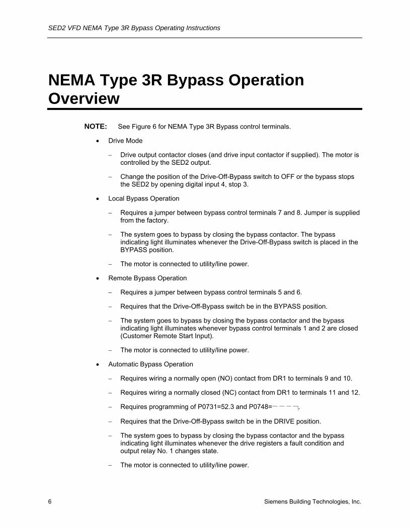
NOTE: See Figure 6 for NEMA Type 3R Bypass control terminals.
• Drive Mode
− Drive output contactor closes (and drive input contactor if supplied). The motor is controlled by the SED2 output.
− Change the position of the Drive-Off-Bypass switch to OFF or the bypass stops the SED2 by opening digital input 4, stop 3.
• Local Bypass Operation
− Requires a jumper between bypass control terminals 7 and 8. Jumper is supplied from the factory.
− The system goes to bypass by closing the bypass contactor. The bypass indicating light illuminates whenever the Drive-Off-Bypass switch is placed in the BYPASS position.
− The motor is connected to utility/line power.
• Remote Bypass Operation
− Requires a jumper between bypass control terminals 5 and 6.
− Requires that the Drive-Off-Bypass switch be in the BYPASS position.
− The system goes to bypass by closing the bypass contactor and the bypass indicating light illuminates whenever bypass control terminals 1 and 2 are closed (Customer Remote Start Input).
− The motor is connected to utility/line power.
• Automatic Bypass Operation
− Requires wiring a normally open (NO) contact from DR1 to terminals 9 and 10.
− Requires wiring a normally closed (NC) contact from DR1 to terminals 11 and 12.
− Requires programming of P0731=52.3 and P0748= .
− Requires that the Drive-Off-Bypass switch be in the DRIVE position.
− The system goes to bypass by closing the bypass contactor and the bypass indicating light illuminates whenever the drive registers a fault condition and output relay No. 1 changes state.
− The motor is connected to utility/line power.

NEMA Type 3R Bypass Operation Overview
Siemens Building Technologies, Inc. 7
− If remote bypass operation is also selected, the motor will not run on bypass until the contact for the Customer Remote Start Input closes.
• Safety Input
− Requires a jumper between bypass control terminals 3 and 4. Jumper is supplied from the factory.
− Contact must be closed for the motor to be run in either the drive or bypass modes.
WARNING: This contact disconnects the 120 Vac control power circuit.
• Essential Service Mode
− Closing terminals 13 and 16 forces the bypass contactor to close regardless of the selected operation.
− All calls to open the bypass contactor are ignored except the opening of this contact or the removal of main power.
WARNING: All calls to open the bypass include ignoring the tripping of the mechanical overload and opening of the safety input. Perform this procedure with extreme care.

SED2 VFD NEMA Type 3R Bypass Operating Instructions
8 Siemens Building Technologies, Inc.
Installation
Environmental Conditions NEMA Type 3R enclosed bypasses are manufactured for outdoor locations, not in direct sunlight. The 3R rating provides a degree of protection to the enclosed VFD and electrical control components from falling rain, snow, and from damage caused by the formation of ice.
The ambient temperature must be between 14°F and 104°F (-10°C to 40°C) and the relative humidity must be 0% to 95% non-condensing. Units with the HT1 designation in their part number are rated to 122°F (50°C).
CAUTION:
1. When locating NEMA Type 3R enclosure, make certain that the heater/finger guard air inlet (Figure 4) is not blocked and that any environmental substance (such as snow or sand) or other debris will not potentially block the air inlet.
2. A heater is supplied with all outdoor enclosures to minimize the effects of condensation. The heater is only powered when the main power to the enclosure is on. If the unit has been de-energized for any period, inspect for and rectify any condensation in the enclosure before reapplying power.
3. The heater should be set above the typical average dew point for your part of the country. If unsure of your typical dew point temperature, 75°F (24°C) should be appropriate for most areas.
Inspection 1. As you unpack the NEMA Type 3R Bypass, check for shipping damage. In the event of
damage, contact the transport company.
2. Locate the NEMA Type 3R Bypass nameplate and confirm that the unit is configured to the installation requirements.
3. Verify that the delivery is complete. If not, contact the supplier.

Installation
Siemens Building Technologies, Inc. 9
Dimensions and Weights Figure 3 shows NEMA Type 3R Bypass dimensions. Table 1 lists approximate weights.
DEPTH = 11-1/2 (292)
ENCLOSURE ABC ENCLOSURE DE
DEPTH = 12-1/2 (318)
ENCLOSURE F
DEPTH = 16-1/2 (419)
MOUNTING CLEARANCE FOR PROPER AIRFLOW:LEAVE 1 FOOT (305 mm) BETWEEN THE NEMA TYPE 3R BYPASS AND ANY ADJACENTSOLID STRUCTURE THAT IS NOT USED FORMOUNTING PURPOSES.
LEAVE 3 FEET (914 mm) BETWEEN THE NEMA TYPE 3R BYPASS AND ANY OTHER NEMA TYPE 3R BYPASS OR VFD.
34 (864)
75(1905)
74-1/8(1882)
58 (1473)
42 (1067)
46 (1169)
57(1448)
56-1/8(1425)
30 (762)
18 (457)
28-1/2 (724)
30 (762)
Figure 3. NEMA Type 3R Bypass Enclosure Dimensions in Inches (Millimeters).
Table 1. Approximate Weights.
Enclosure Size Wt. lb (kg)
ABC 130 (59)
DE 300 (136)
F 550 (249)
NOTE: Actual horsepower/voltage and selected power options affect the actual weight.

SED2 VFD NEMA Type 3R Bypass Operating Instructions
10 Siemens Building Technologies, Inc.
Mounting 1. Punch appropriate conduit holes for control, motor, and input power wiring (Figure 4).
CAUTION: To maintain the NEMA Type 3R enclosure rating, use only fittings rated 3R or rain tight, or for wet locations.
2. Mount NEMA Type 3R Bypass enclosure in location per job drawings.
• To ensure safe installation, verify that the surface of the mounting location is level.
• See Figure 3 for dimensions and see Table 1 for approximate weights.
• Make certain SED2 operator panel, bypass switches, and disconnect are accessible.
• Secure enclosure in place.
CAUTION: Leave 1 foot (305 mm) between the NEMA Type 3R Bypass and any adjacent solid structure that is not used for mounting purposes.
Leave 3 feet (914 mm) between the NEMA Type 3R Bypass and any other NEMA Type 3R Bypass or VFD.
3. Cooling/Filter Note: The NEMA Type 3R Bypass is supplied with an air filter that requires periodic cleaning and/or replacement. The time period is determined by the mounting location and environmental conditions. Ensure that you make filter maintenance part of an established maintenance schedule for your installation.

Installation
Siemens Building Technologies, Inc. 11
BYPASS ON LIGHT
DRIVE-OFF-BYPASS SWITCH
DRIVE TEST ON-OFF SWITCH
DISCONNECTSWITCH
FAN/FINGERGUARD EXHAUST
HEATER/FINGERGUARD AIR INLET CONDUIT LOCATION
(SHADED AREA ONLY)
1 (25)1 (25)
1 (25)12 (305)
DOOR ANTI-LOCKDEFEATABLE MECHANISM
Enclosure ABC.
FAN/FINGERGUARD EXHAUST
1 (25)
1 (25)16 (406)
DISCONNECTSWITCH
1 (25)
BYPASS ON LIGHT
DRIVE-OFF-BYPASS SWITCH
DRIVE TEST ON-OFF SWITCH
HEATER/FINGERGUARD AIR INLET
DOOR ANTI-LOCKDEFEATABLE MECHANISM
CONDUIT LOCATION(SHADED AREA ONLY)
Enclosure DE.
BYPASS ON LIGHT
DRIVE-OFF-BYPASS SWITCH
DRIVE TEST ON-OFF SWITCH
HEATER/FINGERGUARD AIR INLET
FAN/FINGERGUARD EXHAUST
19 (483)
1 (25)
1 (25)
1 (25)
DISCONNECTSWITCH
DOOR ANTI-LOCKDEFEATABLE MECHANISM
CONDUIT LOCATION(SHADED AREA ONLY)
Enclosure F.
Figure 4. NEMA Type 3R Bypass Enclosure Conduit Locations. Dimensions in Inches (Millimeters).

SED2 VFD NEMA Type 3R Bypass Operating Instructions
12 Siemens Building Technologies, Inc.
Wiring Connections
NOTE: See Figures 5 through 10 for all NEMA Type 3R Bypass wiring.
1. Do not mix control, motor, and input wiring in the same conduit. Run separate wire types with maximum possible separation.
WARNING: Failure to follow appropriate VFD wiring practice can result in sub-standard system operation and may damage control components.
2. Route shielded, twisted pair, 24-gauge minimum cable for control wiring in separate conduit into enclosure (Figures 8 through 10). Connect control wiring per job drawings and Figure 6.
NOTES:
• Terminate shield at control device.
• Control wiring is 12 to 26 AWG and tightening torque is 4.4 lb-in (0.5 Nm).
3. If applicable, route communications wiring (P1) in separate conduit into enclosure (Figures 8 through 10). Continue to route communications wiring to VFD and terminate per SED2 VFD Startup, Operation, and Maintenance Manual, (125-3201).
CAUTION: If applicable, route communications wiring with maximum separation from all other wiring. If wiring through bypass enclosure, run communication wiring with maximum separation possible from all other wiring.
4. Route motor wiring in separate conduit into enclosure (Figures 8 through 10). Connect motor wiring to motor overload and ground lug. See Tables 2 through 5 for wire sizes and tightening torques.
5. Route input power wiring in conduit into enclosure (Figures 8 through 10). Connect input power wiring to disconnect switch and ground lug or to circuit breaker and ground lug. See Tables 2 through 5 for wire sizes and tightening torques.
WARNING: Use only permanently wired input power connections.
Installation
Siemens Building Technologies, Inc. 13
1 111098765432
VFD1 CONTROL TERMINALS
RR M2
M2
(6) (10)
M1
(5) (6)
(T1)
OL1 1T1
1T2(T2)
(T3)1T3
M
(1) (2)
M2(1) (2)
U
V(3)
(5) (6)
(4)
W
(3) (4)
U
VFD1
W
GND
V
R
S
T
AC MOTOR(CUSTOMERSUPPLIED)
GNDLUG
GNDGNDLUG
2L1
2L2
2L3
3L1
3L2
3L3
FU11L1
1L2(L1)
L1
L2(T1)
DISC1
M3
(2)
(4)
(6)
1L3(L3)
L3(T3)
GND
(L2)(T2)
1L1 1L2
(5)
(3)
(1)
OPTIONAL SUPPLEMENTARYPOWER FUSES - MAIN SHORT
CIRCUIT PROTECTION BY OTHERS(SEE NOTE 1)
OPTIONALDRIVE INPUTCONTACTOR
POWERSUPPLY3 PHASE
60 Hz
TOSTEP-DOWN
CONTROLTRANSFORMER
B2
A2A1
B1
C2C1
OPTIONALINPUT LINEREACTOR(SUPPLIED
LOOSE)
A2
B2
C2
A1
B1
C1
OPTIONALOUTPUT LOAD
REACTOR(SUPPLIED
LOOSE)
A2
B2
C2
A1
B1
C1
OPTIONALINPUT LINEREACTOR
ONLYSUPPLIEDON UNITS
WITH BYPASS
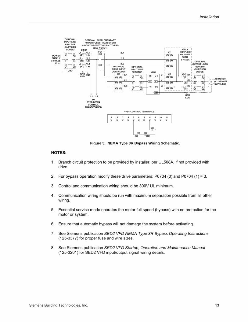
Figure 5. NEMA Type 3R Bypass Wiring Schematic.
NOTES:
1. Branch circuit protection to be provided by installer, per UL508A, if not provided with drive.
2. For bypass operation modify these drive parameters: P0704 (0) and P0704 (1) = 3.
3. Control and communication wiring should be 300V UL minimum.
4. Communication wiring should be run with maximum separation possible from all other wiring.
5. Essential service mode operates the motor full speed (bypass) with no protection for the motor or system.
6. Ensure that automatic bypass will not damage the system before activating.
7. See Siemens publication SED2 VFD NEMA Type 3R Bypass Operating Instructions (125-3377) for proper fuse and wire sizes.
8. See Siemens publication SED2 VFD Startup, Operation and Maintenance Manual (125-3201) for SED2 VFD input/output signal wiring details.

SED2 VFD NEMA Type 3R Bypass Operating Instructions
14 Siemens Building Technologies, Inc.
1 2 3 4 5 6 7 8 9 10 11
RR M210
8
109
105
12 1413 1615 17 2726 2928 30
20 21 22 2423 25
+10V
DC
+0V
DC
AIN
1+
AIN
1-
DIN
1
DIN
2
DIN
3
DIN
4
ISO
24V
DC
AIN
2+
AIN
2-
AO
1+
AO
1-
PT
C A
PT
C B
DIN
5
DIN
6
AO
2+
AO
2-
ISO
0V
DC
P+
N-
RL
1 N
C
RL
1 N
O
RL
1 C
OM
RL
2 N
C
RL
2 N
O
RL
2 C
OM
2 3 2 3 4
1 2 3
2 3 4 9 28
CONTROL TERMINATIONS LOCATEDON DRIVE I/O MODULE.
CONTROL INTER-CONNECTIONBETWEEN BYPASS PANEL.
DRIVE CONTROL TERMINATIONS ANALOG INPUT EXAMPLES
EXTERNAL 0 TO 10V
EXTERNAL 0/4 TO 20mA
+ -+-SPEED
POTENTIOMETER
4.7K OHM
VFD 24 VDC POWERED 0/4 mA DEVICE
(POWER CONSUMPTION CANNOT EXCEED 100mA)
POWERmA
M2
BYPASS CONTROL TERMINATIONS
1 32 54 6 87 109 11 12 13 14
CONTROL TERMINATIONS LOCATEDIN BYPASS ENCLOSURE CBT-1.
15 16
CUSTOMERREMOTESTART
PROVIDEDRY
CONTACT
INSTALLJUMPER
FOR LOCALBYPASS
OPERATION
CUSTOMERSUPPLIEDSAFETIES
ESSENTIALSERVICEENABLED
INSTALLJUMPER
FOR REMOTEBYPASS
OPERATION
TERMINALS 9 THROUGH 12 ARE USED FOR AUTO BYPASS
FEATURE. IF USING THIS FEATURE, SEE INSTRUCTION
FOR WIRING AND FOR DRIVE PROGRAMMING.
ESSENTIALSERVICEACTIVE
PROVIDEDRY
CONTACTWITH
JUMPER
SHIPPEDWITH
JUMPER
JUMPERINSTALLED
FOR NON-AUTO
BYPASSOPERATION
PROVIDEDRY
CONTACT
PROVIDEDRY
CONTACT
17
NOT FORCUSTOMER
USE
Figure 6. NEMA Type 3R Bypass Control Terminals.
Installation
Siemens Building Technologies, Inc. 15
xoo
5 OL1
OFF
5
[X1]
DRIVE
[X2]
[H1] [H4]
xoo
BYPASS
X2
1L2116116
1L1
FU
2
[H3] [H2]
FU3
[XF]
ESRESSENTIAL SERVICERELAY3
JUMPER
CUSTOMERSUPPLIEDSAFETIES
ESSENTIALSERVICEENABLED
4 1
2
4 3
13 14 15 16
RUNCUSTOMERREMOTESTART
1 2 RR6 RELAY5
oox
xoo
9 5 6RR
7 8
(96) (95)
8 10 11 12
10 12
M1BYPASSCONTACTOR
M213
A LIGHTBYPASS
(8)E
SR (1
2)
ESR M1 CONTACTORVFD OUTPUT
17M2
1615
VFD INPUTCONTACTOR18
M3
OFFON
xo
DRIVE TEST
ONLY SUPPLIED WITH OPTIONAL THREE CONTACTORBYPASS (ADDITION OF DRIVE INPUT CONTACTOR).
INSTALL JUMPERFOR REMOTE BYPASS
OPERATION
5 7DR1
DRIVERELAY #1
21
VFD1 (CONTROL TERMINALS)
22
TRANSFORMER PRIMARY CONTACTS:230/460/575v PRIMARY VOLTAGE. ACTUAL CONNECTIONS VARY WITH VOLTAGE.
SECONDARY VOLTAGE 115 VAC
DR#2FAN
HEATDR#2
ESSENTIALSERVICEACTIVE (14) (13)
(14) (13)
5 7DR2
DRIVERELAY#2(MUST ALWAYS BE PROGRAMMED TO RUN)
24
VFD1 (CONTROL TERMINALS)
25
(14) (13)
(14) (13)
10
INSTALL JUMPERFOR LOCAL BYPASS
OPERATION
(SHIPPED WITHOUTJUMPER)
(SHIPPED WITHJUMPER)
(12) (8)(A1) (A2)
(A1) (A2)
(A1) (A2)
14(10) (2)
11 12
INSTALL JUMPERFOR NORMALOPERATION
(SHIPPED WITHJUMPER)
X TERMINAL NUMBER X ON CBT-1.
SUPPLIED ON UNITS THAT DO NOT HAVE BYPASS.
SUPPLIED ON UNITS THAT DO NOT HAVE BYPASS.
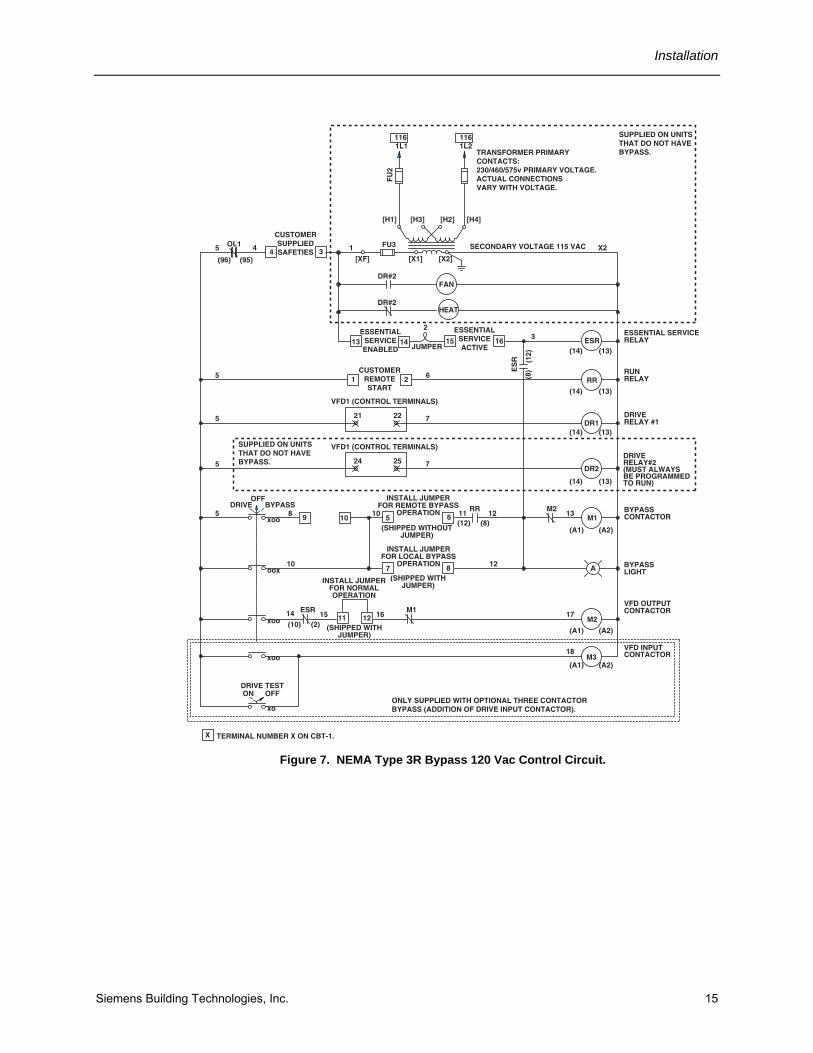
Figure 7. NEMA Type 3R Bypass 120 Vac Control Circuit.

SED2 VFD NEMA Type 3R Bypass Operating Instructions
16 Siemens Building Technologies, Inc.
BYPASS CONTACTOR
BAFFLE
GROMMETS (5)
HEATER
SED2 VFDFRAME SIZE C
INPUT CONTACTOR
TERMINAL BLOCK
OUTPUT CONTACTOR
LINE REACTOR
RELAYS
CONTROL TRANSFORMER
POWER FUSES
AIR FILTER
FAN
DISCONNECT GROUND LUGS (2)MOTOR OVERLOAD
INPUT POWERWIRING
T1 T3T2L1 L3L2
MOTOR OVERLOAD
DISCONNECT
GROUND LUGS
INPUT POWER WIRINGTO DISCONNECTL1, L2, L3 AND TO
GROUND LUG
MOTOR WIRING TOMOTOR OVERLOADT1, T2, T3, AND TO
GROUND LUG
MOTORWIRING
CONTROLWIRING
Figure 8. Routing of Power and Control Wiring for Enclosure Size ABC.
SED2 VFDFRAME SIZE E
TERMINAL BLOCK
BYPASS CONTACTOR
DISCONNECT
GROUND LUGS (2)
MOTOR OVERLOAD
CONTROL TRANSFORMER
INPUT CONTACTOR
BAFFLE
GROMMETS (5)
HEATER
MOTORWIRING
INPUT POWERWIRING
T1 T3T2L1 L3L2
MOTOR OVERLOAD
DISCONNECT
GROUND LUGS
INPUT POWER WIRINGTO DISCONNECTL1, L2, L3 AND TO
GROUND LUG
MOTOR WIRING TOMOTOR OVERLOADT1, T2, T3, AND TO
GROUND LUG
CONTROLWIRING
LINE REACTOR
OUTPUT CONTACTOR
POWER FUSES
AIR FILTER
FAN
Figure 9. Routing of Power and Control Wiring for Enclosure Size DE.

Installation
Siemens Building Technologies, Inc. 17
SED2 VFDFRAME SIZE F
INPUT CONTACTOR
BAFFLE
GROMMETS (5)
HEATER
MOTORWIRING
INPUT POWERWIRING
CONTROLWIRING
T1 T3T2L1 L3L2
MOTOR OVERLOAD
DISCONNECT
GROUND LUGS
INPUT POWER WIRINGTO DISCONNECTL1, L2, L3 AND TO
GROUND LUG
MOTOR WIRING TOMOTOR OVERLOADT1, T2, T3, AND TO
GROUND LUG
TERMINAL BLOCK
DISCONNECT
GROUND LUGS (2)
MOTOR OVERLOAD
OUTPUT CONTACTOR
BYPASS CONTACTOR
LINE REACTOR
CONTROL TRANSFORMERPOWER FUSES
AIR FILTER
FAN
Figure 10. Routing of Power and Control Wiring for Enclosure Size F.

SED2 VFD NEMA Type 3R Bypass Operating Instructions
18 Siemens Building Technologies, Inc.
Motor Cable Length Motor cable length is given to ensure performance of only the drive, not the suitability of the motor when connected to a drive at this distance.
• Maximum motor cable length is 164 ft (50 m).
• See Figure 11 for installation notes.
MSED2
3. If needed, use SBT-specified input line reactors to ensure a good impedance match with your drive.
1. Never run control or drive input wires in the same conduit as
the drive output wires.
4. If a disconnect is mounted on the load side of your drive, it is desirable to wire an auxiliary contact to the drive that will disable drive operation when the disconnect opens. (The wiring for this contact must not be run in the same conduit as the drive output wires).
5. Inverter duty motors are recommended. Install motors within their guidelines. Use dV/dT filters, output reactors, or other load conditioners as applicable or as specifiedby the motor manufacturer. Reactor products must be mounted next to the drive.
2. Keep the distance from the drive to the motor as short as possible
to maximize motor life.
VF
D00
14R
3
!
Figure 11. Motor Cable Installation Notes.
Installation
Siemens Building Technologies, Inc. 19
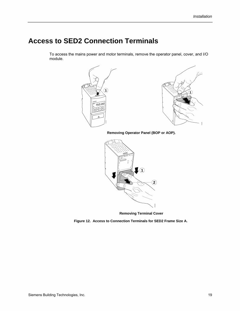
Access to SED2 Connection Terminals To access the mains power and motor terminals, remove the operator panel, cover, and I/O module.
5192
J08
1
5192
J09
1
Removing Operator Panel (BOP or AOP).
5192
J16
2
1
Removing Terminal Cover
Figure 12. Access to Connection Terminals for SED2 Frame Size A.

SED2 VFD NEMA Type 3R Bypass Operating Instructions
20 Siemens Building Technologies, Inc.
1
VF
D00
68R
1
Figure 13. Access to Connection Terminals for SED2 Frame Size B and C.
3
1
2
5
6
451
92J 1
3
Figure 14. Access to Connection Terminals for SED2 Frame Size D and E.

Installation
Siemens Building Technologies, Inc. 21
2
3
4
1
5192J14
5
6
Figure 15. Access to Connection Terminals for SED2 Frame Size F.
SED2 VFD NEMA Type 3R Bypass Operating Instructions
22 Siemens Building Technologies, Inc.
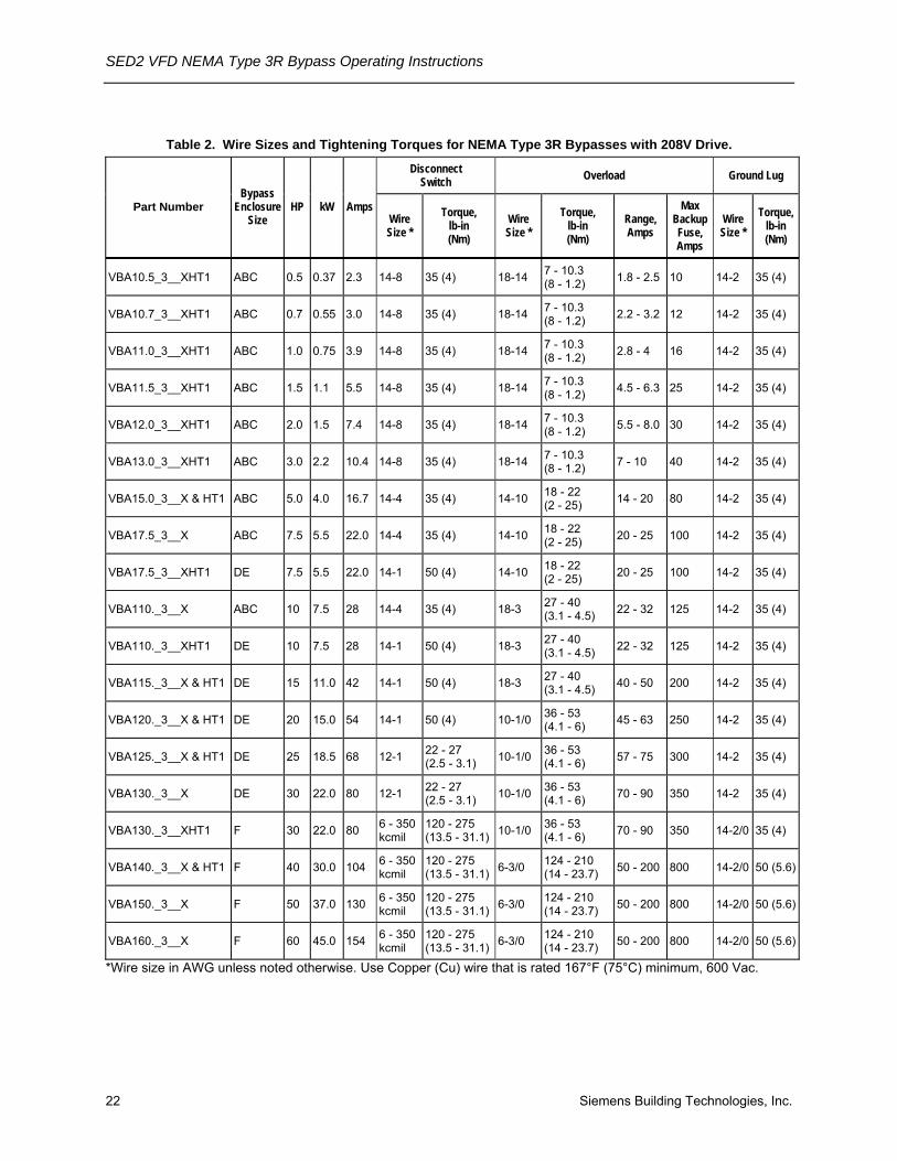
Table 2. Wire Sizes and Tightening Torques for NEMA Type 3R Bypasses with 208V Drive.
Disconnect Switch Overload Ground Lug
Part Number Bypass
Enclosure Size
HP kW Amps Wire Size *
Torque, lb-in (Nm)
Wire Size *
Torque, lb-in (Nm)
Range, Amps
Max Backup Fuse, Amps
Wire Size *
Torque, lb-in (Nm)
VBA10.5_3__XHT1 ABC 0.5 0.37 2.3 14-8 35 (4) 18-14 7 - 10.3 (8 - 1.2) 1.8 - 2.5 10 14-2 35 (4)
VBA10.7_3__XHT1 ABC 0.7 0.55 3.0 14-8 35 (4) 18-14 7 - 10.3 (8 - 1.2) 2.2 - 3.2 12 14-2 35 (4)
VBA11.0_3__XHT1 ABC 1.0 0.75 3.9 14-8 35 (4) 18-14 7 - 10.3 (8 - 1.2) 2.8 - 4 16 14-2 35 (4)
VBA11.5_3__XHT1 ABC 1.5 1.1 5.5 14-8 35 (4) 18-14 7 - 10.3 (8 - 1.2) 4.5 - 6.3 25 14-2 35 (4)
VBA12.0_3__XHT1 ABC 2.0 1.5 7.4 14-8 35 (4) 18-14 7 - 10.3 (8 - 1.2) 5.5 - 8.0 30 14-2 35 (4)
VBA13.0_3__XHT1 ABC 3.0 2.2 10.4 14-8 35 (4) 18-14 7 - 10.3 (8 - 1.2) 7 - 10 40 14-2 35 (4)
VBA15.0_3__X & HT1 ABC 5.0 4.0 16.7 14-4 35 (4) 14-10 18 - 22 (2 - 25) 14 - 20 80 14-2 35 (4)
VBA17.5_3__X ABC 7.5 5.5 22.0 14-4 35 (4) 14-10 18 - 22 (2 - 25) 20 - 25 100 14-2 35 (4)
VBA17.5_3__XHT1 DE 7.5 5.5 22.0 14-1 50 (4) 14-10 18 - 22 (2 - 25) 20 - 25 100 14-2 35 (4)
VBA110._3__X ABC 10 7.5 28 14-4 35 (4) 18-3 27 - 40 (3.1 - 4.5) 22 - 32 125 14-2 35 (4)
VBA110._3__XHT1 DE 10 7.5 28 14-1 50 (4) 18-3 27 - 40 (3.1 - 4.5) 22 - 32 125 14-2 35 (4)
VBA115._3__X & HT1 DE 15 11.0 42 14-1 50 (4) 18-3 27 - 40 (3.1 - 4.5) 40 - 50 200 14-2 35 (4)
VBA120._3__X & HT1 DE 20 15.0 54 14-1 50 (4) 10-1/0 36 - 53 (4.1 - 6) 45 - 63 250 14-2 35 (4)
VBA125._3__X & HT1 DE 25 18.5 68 12-1 22 - 27 (2.5 - 3.1) 10-1/0 36 - 53
(4.1 - 6) 57 - 75 300 14-2 35 (4)
VBA130._3__X DE 30 22.0 80 12-1 22 - 27 (2.5 - 3.1) 10-1/0 36 - 53
(4.1 - 6) 70 - 90 350 14-2 35 (4)
VBA130._3__XHT1 F 30 22.0 80 6 - 350 kcmil
120 - 275 (13.5 - 31.1) 10-1/0 36 - 53
(4.1 - 6) 70 - 90 350 14-2/0 35 (4)
VBA140._3__X & HT1 F 40 30.0 104 6 - 350 kcmil
120 - 275 (13.5 - 31.1) 6-3/0 124 - 210
(14 - 23.7) 50 - 200 800 14-2/0 50 (5.6)
VBA150._3__X F 50 37.0 130 6 - 350 kcmil
120 - 275 (13.5 - 31.1) 6-3/0 124 - 210
(14 - 23.7) 50 - 200 800 14-2/0 50 (5.6)
VBA160._3__X F 60 45.0 154 6 - 350 kcmil
120 - 275 (13.5 - 31.1) 6-3/0 124 - 210
(14 - 23.7) 50 - 200 800 14-2/0 50 (5.6)
*Wire size in AWG unless noted otherwise. Use Copper (Cu) wire that is rated 167°F (75°C) minimum, 600 Vac.

Installation
Siemens Building Technologies, Inc. 23
Table 3. Wire Sizes and Tightening Torques for NEMA Type 3R Bypasses with 230V - 240V Drive.
Disconnect Switch Overload Ground Lug
Part Number
Bypass Enclosure
Size
HP kW Amps Wire Size *
Torque, lb-in (Nm)
Wire Size *
Torque, lb-in (Nm)
Range, Amps
Max Backup Fuse, Amps
Wire Size *
Torque, lb-in (Nm)
VBA20.5_3__XHT1 ABC 0.5 0.37 2.2 14-8 35 (4) 18-14 7 - 10.3 (8 - 1.2) 1.8 - 2.5 10 14-2 35 (4)
VBA20.7_3__XHT1 ABC 0.7 0.55 3.0 14-8 35 (4) 18-14 7 - 10.3 (8 - 1.2) 2.2 - 3.2 12 14-2 35 (4)
VBA21.0_3__XHT1 ABC 1.0 0.75 3.9 14-8 35 (4) 18-14 7 - 10.3 (8 - 1.2) 2.8 - 4 16 14-2 35 (4)
VBA21.5_3__XHT1 ABC 1.5 1.1 5.5 14-8 35 (4) 18-14 7 - 10.3 (8 - 1.2) 4.5 - 6.3 25 14-2 35 (4)
VBA22.0_3__XHT1 ABC 2.0 1.5 6.8 14-8 35 (4) 18-14 7 - 10.3 (8 - 1.2) 5.5 - 8.0 30 14-2 35 (4)
VBA23.0_3__XHT1 ABC 3.0 2.2 9.6 14-8 35 (4) 18-14 7 - 10.3 (8 - 1.2) 7 - 10 40 14-2 35 (4)
VBA25.0_3__XHT1 ABC 5.0 4.0 15.2 14-4 35 (4) 14-10 18 - 22 (2 - 25) 14 - 20 80 14-2 35 (4)
VBA27.5_3__X ABC 7.5 5.5 22 14-4 35 (4) 14-10 18 - 22 (2 - 25) 20 - 25 100 14-2 35 (4)
VBA27.5_3__XHT1 DE 7.5 5.5 22 14-1 50 (4) 14-10 18 - 22 (2 - 25) 20 - 25 100 14-2 35 (4)
VBA210_3__X ABC 10 7.5 28 14-4 35 (4) 18-3 27 - 40 (3.1 - 4.5) 22 - 32 125 14-2 35 (4)
VBA210_3__XHT1 DE 10 7.5 28 14-1 50 (4) 18-3 27 - 40 (3.1 - 4.5) 22 - 32 125 14-2 35 (4)
VBA215_3__X & HT1 DE 15 11.0 42 14-1 50 (4) 18-3 27 - 40 (3.1 - 4.5) 40 - 50 200 14-2 35 (4)
VBA220_3__X & HT1 DE 20 15.0 54 14-1 50 (4) 10-1/0 36 - 53 (4.1 - 6) 45 - 63 250 14-2 35 (4)
VBA225_3__X & HT1 DE 25 18.5 68 12-1 22 - 27 (2.5 - 3.1) 10-1/0 36 - 53
(4.1 - 6) 57 - 75 300 14-2 35 (4)
VBA230_3__X DE 30 22.0 80 12-1 22 - 27 (2.5 - 3.1) 10-1/0 36 - 53
(4.1 - 6) 70 - 90 350 14-2 35 (4)
VBA230_3__XHT1 F 30 22.0 80 6 - 350 kcmil
120 - 275 (13.5 - 31.1) 10-1/0 36 - 53
(4.1 - 6) 70 - 90 350 14-2/0 35 (4)
VBA240_3__X & HT1 F 40 30.0 104 6 - 350 kcmil
120 - 275 (13.5 - 31.1) 6-3/0 124 - 210
(14 - 23.7) 50 - 200 800 14-2/0 50 (5.6)
VBA250_3__X F 50 37.0 130 6 - 350 kcmil
120 - 275 (13.5 - 31.1) 6-3/0 124 - 210
(14 - 23.7) 50 - 200 800 14-2/0 50 (5.6)
VBA260_3__X F 60 45.0 154 6 - 350 kcmil
120 - 275 (13.5 - 31.1) 6-3/0 124 - 210
(14 - 23.7) 50 - 200 800 14-2/0 50 (5.6)
* Wire size is AWG unless noted otherwise. Use Copper (Cu) wire that is rated 167°F (75°C) minimum 600 Vac.
SED2 VFD NEMA Type 3R Bypass Operating Instructions
24 Siemens Building Technologies, Inc.
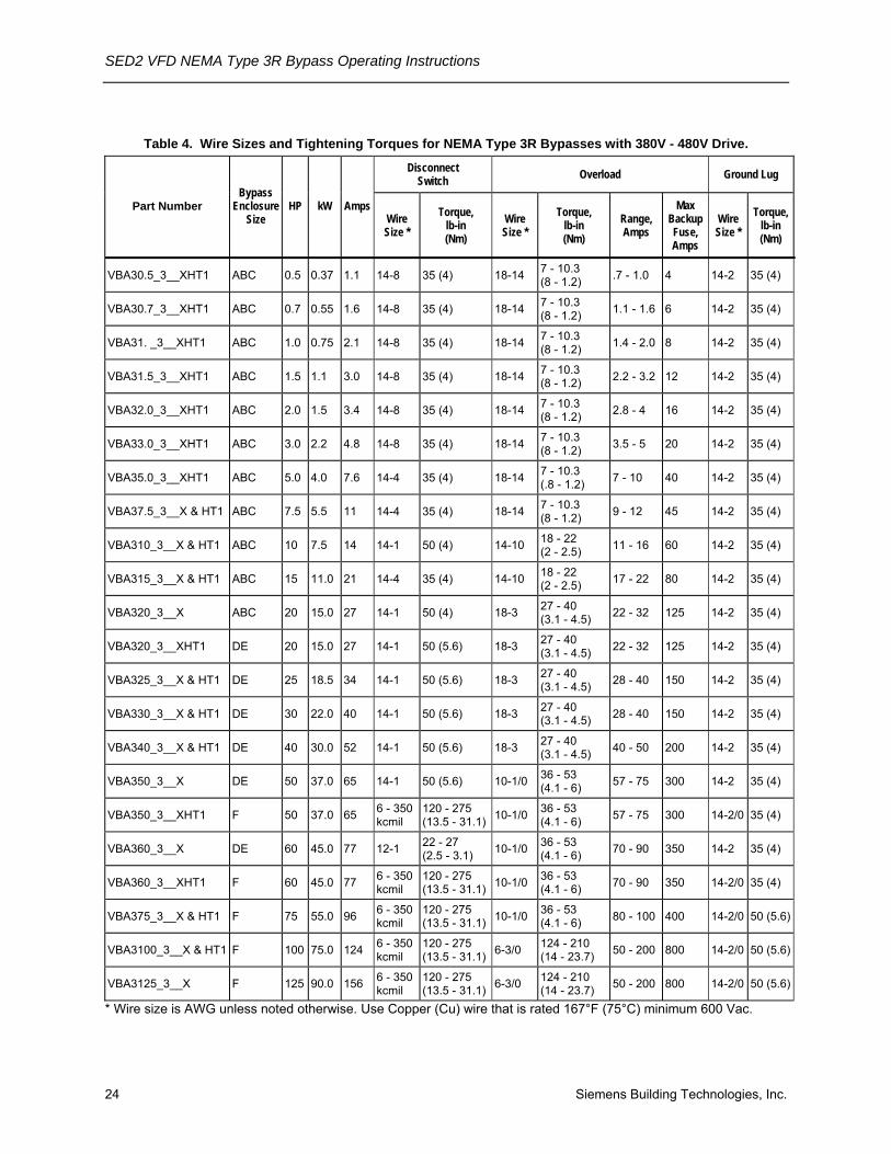
Table 4. Wire Sizes and Tightening Torques for NEMA Type 3R Bypasses with 380V - 480V Drive.
Disconnect Switch Overload Ground Lug
Part Number Bypass
Enclosure Size
HP kW Amps Wire Size *
Torque, lb-in (Nm)
Wire Size *
Torque, lb-in (Nm)
Range, Amps
Max Backup Fuse, Amps
Wire Size *
Torque, lb-in (Nm)
VBA30.5_3__XHT1 ABC 0.5 0.37 1.1 14-8 35 (4) 18-14 7 - 10.3 (8 - 1.2) .7 - 1.0 4 14-2 35 (4)
VBA30.7_3__XHT1 ABC 0.7 0.55 1.6 14-8 35 (4) 18-14 7 - 10.3 (8 - 1.2) 1.1 - 1.6 6 14-2 35 (4)
VBA31. _3__XHT1 ABC 1.0 0.75 2.1 14-8 35 (4) 18-14 7 - 10.3 (8 - 1.2) 1.4 - 2.0 8 14-2 35 (4)
VBA31.5_3__XHT1 ABC 1.5 1.1 3.0 14-8 35 (4) 18-14 7 - 10.3 (8 - 1.2) 2.2 - 3.2 12 14-2 35 (4)
VBA32.0_3__XHT1 ABC 2.0 1.5 3.4 14-8 35 (4) 18-14 7 - 10.3 (8 - 1.2) 2.8 - 4 16 14-2 35 (4)
VBA33.0_3__XHT1 ABC 3.0 2.2 4.8 14-8 35 (4) 18-14 7 - 10.3 (8 - 1.2) 3.5 - 5 20 14-2 35 (4)
VBA35.0_3__XHT1 ABC 5.0 4.0 7.6 14-4 35 (4) 18-14 7 - 10.3 (.8 - 1.2) 7 - 10 40 14-2 35 (4)
VBA37.5_3__X & HT1 ABC 7.5 5.5 11 14-4 35 (4) 18-14 7 - 10.3 (8 - 1.2) 9 - 12 45 14-2 35 (4)
VBA310_3__X & HT1 ABC 10 7.5 14 14-1 50 (4) 14-10 18 - 22 (2 - 2.5) 11 - 16 60 14-2 35 (4)
VBA315_3__X & HT1 ABC 15 11.0 21 14-4 35 (4) 14-10 18 - 22 (2 - 2.5) 17 - 22 80 14-2 35 (4)
VBA320_3__X ABC 20 15.0 27 14-1 50 (4) 18-3 27 - 40 (3.1 - 4.5) 22 - 32 125 14-2 35 (4)
VBA320_3__XHT1 DE 20 15.0 27 14-1 50 (5.6) 18-3 27 - 40 (3.1 - 4.5) 22 - 32 125 14-2 35 (4)
VBA325_3__X & HT1 DE 25 18.5 34 14-1 50 (5.6) 18-3 27 - 40 (3.1 - 4.5) 28 - 40 150 14-2 35 (4)
VBA330_3__X & HT1 DE 30 22.0 40 14-1 50 (5.6) 18-3 27 - 40 (3.1 - 4.5) 28 - 40 150 14-2 35 (4)
VBA340_3__X & HT1 DE 40 30.0 52 14-1 50 (5.6) 18-3 27 - 40 (3.1 - 4.5) 40 - 50 200 14-2 35 (4)
VBA350_3__X DE 50 37.0 65 14-1 50 (5.6) 10-1/0 36 - 53 (4.1 - 6) 57 - 75 300 14-2 35 (4)
VBA350_3__XHT1 F 50 37.0 65 6 - 350 kcmil
120 - 275 (13.5 - 31.1) 10-1/0 36 - 53
(4.1 - 6) 57 - 75 300 14-2/0 35 (4)
VBA360_3__X DE 60 45.0 77 12-1 22 - 27 (2.5 - 3.1) 10-1/0 36 - 53
(4.1 - 6) 70 - 90 350 14-2 35 (4)
VBA360_3__XHT1 F 60 45.0 77 6 - 350 kcmil
120 - 275 (13.5 - 31.1) 10-1/0 36 - 53
(4.1 - 6) 70 - 90 350 14-2/0 35 (4)
VBA375_3__X & HT1 F 75 55.0 96 6 - 350 kcmil
120 - 275 (13.5 - 31.1) 10-1/0 36 - 53
(4.1 - 6) 80 - 100 400 14-2/0 50 (5.6)
VBA3100_3__X & HT1 F 100 75.0 124 6 - 350 kcmil
120 - 275 (13.5 - 31.1) 6-3/0 124 - 210
(14 - 23.7) 50 - 200 800 14-2/0 50 (5.6)
VBA3125_3__X F 125 90.0 156 6 - 350 kcmil
120 - 275 (13.5 - 31.1) 6-3/0 124 - 210
(14 - 23.7) 50 - 200 800 14-2/0 50 (5.6)
* Wire size is AWG unless noted otherwise. Use Copper (Cu) wire that is rated 167°F (75°C) minimum 600 Vac.

Installation
Siemens Building Technologies, Inc. 25
Table 5. Wire Sizes and Tightening Torques for NEMA Type 3R Bypasses with 500V - 600V Drive. Disconnect
Switch Overload Ground Lug
Part Number Bypass
Enclosure Size
HP kW Amps Wire Size *
Torque, lb-in (Nm)
Wire Size *
Torque, lb-in (Nm)
Range, Amps
Max Backup Fuse, Amps
Wire Size *
Torque, lb-in (Nm)
VBA40.5_3__X & HT1 ABC 0.5 0.37 .9 14-8 35 (4) 18-14 7 - 10.3 (8 - 1.2) .7 - 1.0 4 14-2 35 (4)
VBA40.7_3__X & HT1 ABC 0.7 0.55 1.3 14-8 35 (4) 18-14 7 - 10.3 (8 - 1.2) .9 - 1.25 5 14-2 35 (4)
VBA41.0_3__X & HT1 ABC 1.0 0.75 1.4 14-8 35 (4) 18-14 7 - 10.3 (8 - 1.2) 1.1 - 1.6 6 14-2 35 (4)
VBA41.5_3__X & HT1 ABC 1.5 1.1 2.1 14-8 35 (4) 18-14 7 - 10.3 (8 - 1.2) 1.8 - 2.5 10 14-2 35 (4)
VBA42.0_3__X & HT1 ABC 2.0 1.5 2.7 14-8 35 (4) 18-14 7 - 10.3 (8 - 1.2) 2.2 - 3.2 12 14-2 35 (4)
VBA43.0_3__X & HT1 ABC 3.0 2.2 3.9 14-8 35 (4) 18-14 7 - 10.3 (8 - 1.2) 2.8 - 4 16 14-2 35 (4)
VBA45.0_3__X & HT1 ABC 5.0 4.0 6.1 14-4 35 (4) 18-14 7 - 10.3 (8 - 1.2) 4.5 - 6.3 25 14-2 35 (4)
VBA47.5_3__X & HT1 ABC 7.5 5.5 9 14-4 35 (4) 18-14 7 - 10.3 (8 - 1.2) 7 - 10 40 14-2 35 (4)
VBA410._3__X & HT1 ABC 10 7.5 11 14-1 50 (4) 18-14 7 - 10.3 (8 - 1.2) 9 - 2 45 14-2 35 (4)
VBA415._3__X ABC 15 11.0 17 14-4 35 (4) 14-10 18 - 22 (2 - 2.5) 14 - 20 80 14-2 35 (4)
VBA415._3__XHT1 DE 15 11.0 17 14-1 50 (4) 14-10 18 - 22 (2 - 2.5) 14 - 20 80 14-2 35 (4)
VBA420._3__X ABC 20 15.0 22 14-4 35 (4) 14-10 18 - 22 (2 - 2.5) 17 - 22 80 14-2 35 (4)
VBA420._3__XHT1 DE 20 15.0 22 14-4 35 (4) 14-10 18 - 22 (2 - 2.5) 17 - 22 80 14-2 35 (4)
VBA425._3__X & HT1 DE 25 18.5 27 14-1 50 (5.6) 18-3 27 - 40 (3.1 - 4.5) 22 - 32 125 14-2 35 (4)
VBA430._3__X & HT1 DE 30 22.0 32 14-1 50 (5.6) 18-3 27 - 40 (3.1 - 4.5) 28 - 40 150 14-2 35 (4)
VBA440._3__X & HT1 DE 40 30.0 41 14-1 50 (5.6) 18-3 27 - 40 (3.1 - 4.5) 36 - 45 175 14-2 35 (4)
VBA450._3__X DE 50 37.0 52 14-1 50 (5.6) 18-3 27 - 40 (3.1 - 4.5) 40 - 50 200 14-2 35 (4)
VBA450._3__XHT1 F 50 37.0 52 6 - 350 kcmil
120 - 275 (14 - 31.1) 18-3 27 - 40
(3.1 - 4.5) 40 - 50 200 14-2/0 35 (4)
VBA460._3__X DE 60 45.0 62 12-1 22 - 27 (2.5 - 3.1) 10-1/0 36 - 53
(4.1 - 6) 45 - 63 250 14-2 35 (4)
VBA460._3__XHT1 F 60 45.0 62 6 - 350 kcmil
120 - 275 (14 - 31.1) 10-1/0 36 - 53
(4.1 - 6) 45 - 63 250 14-2/0 35 (4)
VBA475._3__X & HT1 F 75 55.0 77 6 - 350 kcmil
120 - 275 (14 - 31.1) 10-1/0 36 - 53
(4.1 - 6) 70 - 90 350 14-2/0 50 (5.6)
VBA4100_3__X F 100 75.0 99 6 - 350 kcmil
120 - 275 (14 - 31.1) 10-1/0 36 - 53
(4.1 - 6) 80 - 100 400 14-2/0 50 (5.6)
VBA4125_3__X F 125 90.0 125 6 - 350 kcmil
120 - 275 (14 - 31.1) 10-1/0 124 - 210
(14 - 23.7) 50 - 200 800 14-2/0 50 (5.6)
* Wire Size in AWG unless noted otherwise. Use Copper (Cu) wire that is rated 167°F (75°C) minimum, 600 Vac.

SED2 VFD NEMA Type 3R Bypass Operating Instructions
26 Siemens Building Technologies, Inc.
Startup Procedures NOTE: The NEMA Type 3R Bypass does not allow access to the drive display during
normal operation. For startup and programming of the drive, the enclosure door must be open with power applied. This can be done by using the door anti-lock defeatable mechanism (Figure 4) or by manually actuating the disconnect. This should be done with extreme care, as high voltage will be present. Also, do not stand directly in front of live parts when first applying power.
Preparation Check Step
( ) 1. The SED2 is thoroughly tested at the factory. Verify that the drive is free of shipping and installation damage. Shipping damage is not covered by the Siemens warranty; claims must be filed directly with the shipping company as soon as possible.
( ) 2. Review the SED2 VFD Startup, Operation, and Maintenance Manual (125-3201). Review option instructions and schematics.
( ) 3. Verify that the model numbers and the voltage ratings are as specified in the purchase order by matching the nameplate data for each unit to the purchase order.
( ) 4. Verify that the drive has been installed in accordance with the mechanical and electrical installation sections in the SED2 VFD Startup, Operation, and Maintenance Manual (125-3201). Also, verify that the NEMA Type 3R Bypass has been installed in accordance with the Environmental Conditions section of this manual.
CAUTION:
Failure to comply with mechanical and electrical installation requirements may void the product warranty.
( ) 5. Verify that the 50/60 Hz DIP switch has been set to the appropriate setting, as instructed in SED2 VFD Startup, Operation, and Maintenance Manual (125-3201).
( ) 6. Inspect the security of the supply line power, ground connections, and all control circuit connections as identified in the SED2 documents.
IMPORTANT: Confirm that the incoming line power supply connects to the drive input terminals (L1(r), L2(s), L3(t)) and NOT to the output motor terminals (T1(u), T2(v), T3(w)).
IMPORTANT: Double check all power wires (L1(r), L2(s), L3(t)) and motor wires (T1(u), T2(v), T3(w)) to make sure that they are securely tightened down to their respective lugs. Loose wire connections may cause problems at any time, and are not covered under warranty.
Startup Procedures
Siemens Building Technologies, Inc. 27
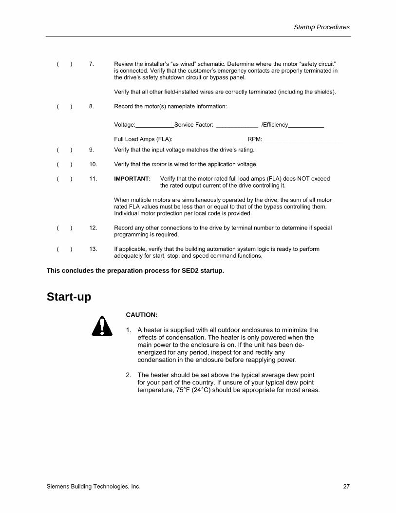
( ) 7. Review the installer’s “as wired” schematic. Determine where the motor “safety circuit” is connected. Verify that the customer’s emergency contacts are properly terminated in the drive’s safety shutdown circuit or bypass panel.
Verify that all other field-installed wires are correctly terminated (including the shields).
( ) 8. Record the motor(s) nameplate information:
Voltage: Service Factor: _____________ /Efficiency
Full Load Amps (FLA): ______________________ RPM: _________________________
( ) 9. Verify that the input voltage matches the drive’s rating.
( ) 10. Verify that the motor is wired for the application voltage.
( ) 11. IMPORTANT: Verify that the motor rated full load amps (FLA) does NOT exceed the rated output current of the drive controlling it.
When multiple motors are simultaneously operated by the drive, the sum of all motor rated FLA values must be less than or equal to that of the bypass controlling them. Individual motor protection per local code is provided.
( ) 12. Record any other connections to the drive by terminal number to determine if special programming is required.
( ) 13. If applicable, verify that the building automation system logic is ready to perform adequately for start, stop, and speed command functions.
This concludes the preparation process for SED2 startup.
Start-up
CAUTION:
1. A heater is supplied with all outdoor enclosures to minimize the effects of condensation. The heater is only powered when the main power to the enclosure is on. If the unit has been de-energized for any period, inspect for and rectify any condensation in the enclosure before reapplying power.
2. The heater should be set above the typical average dew point for your part of the country. If unsure of your typical dew point temperature, 75°F (24°C) should be appropriate for most areas.
SED2 VFD NEMA Type 3R Bypass Operating Instructions
28 Siemens Building Technologies, Inc.
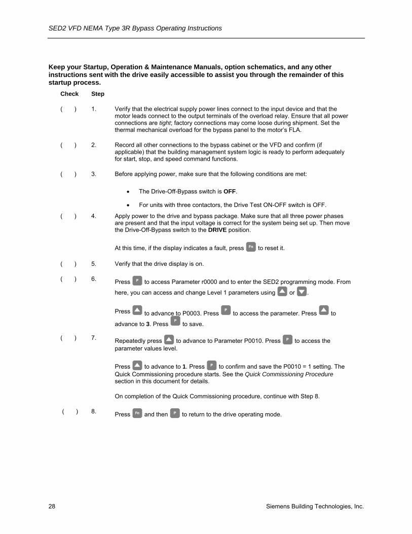
Keep your Startup, Operation & Maintenance Manuals, option schematics, and any other instructions sent with the drive easily accessible to assist you through the remainder of this startup process.
Check Step
( ) 1. Verify that the electrical supply power lines connect to the input device and that the motor leads connect to the output terminals of the overload relay. Ensure that all power connections are tight; factory connections may come loose during shipment. Set the thermal mechanical overload for the bypass panel to the motor’s FLA.
( ) 2. Record all other connections to the bypass cabinet or the VFD and confirm (if applicable) that the building management system logic is ready to perform adequately for start, stop, and speed command functions.
( ) 3. Before applying power, make sure that the following conditions are met:
• The Drive-Off-Bypass switch is OFF.
• For units with three contactors, the Drive Test ON-OFF switch is OFF.
( ) 4. Apply power to the drive and bypass package. Make sure that all three power phases are present and that the input voltage is correct for the system being set up. Then move the Drive-Off-Bypass switch to the DRIVE position.
At this time, if the display indicates a fault, press to reset it.
( ) 5. Verify that the drive display is on.
( ) 6. Press to access Parameter r0000 and to enter the SED2 programming mode. From
here, you can access and change Level 1 parameters using or .
Press to advance to P0003. Press to access the parameter. Press to
advance to 3. Press to save.
( ) 7. Repeatedly press to advance to Parameter P0010. Press to access the parameter values level.
Press to advance to 1. Press to confirm and save the P0010 = 1 setting. The Quick Commissioning procedure starts. See the Quick Commissioning Procedure section in this document for details.
On completion of the Quick Commissioning procedure, continue with Step 8.
( ) 8. Press and then to return to the drive operating mode.

Startup Procedures
Siemens Building Technologies, Inc. 29
( ) 9. To start the Drive, press and then (green start key). The drive will ramp up to “10 HZ” (or minimum speed). Verify that the direction of motor rotation is correct.
NOTE: If the direction of motor rotation is wrong, turn the Drive-Off-Bypass switch to OFF; and turn Power Off! Wait for five minutes. Swap wires on the motor terminals (T1(u), T2(v)) or on the output terminals of the motor overload relay. Tighten the terminal lugs, reapply power, turn Drive-Off-Bypass switch to DRIVE, and recheck the direction of motor rotation.
( ) 10. With correct motor rotation, manually run the drive throughout its entire operating range while observing operation.
• If the drive trips on over-current during acceleration, adjust the acceleration time rate via Parameter P1120.
• If the drive trips on over-voltage during deceleration, adjust the deceleration time rate via Parameter P1121.
• If excessive vibration of the driven load is noted at specific input frequencies, use Skip Frequency Parameters P1091 through P1094 to eliminate this vibration.
( ) 11. Determine whether the remote speed reference is a 0 to 10 Vdc or a 4 to 20 mA signal. Connect signal wires and place analog input DIP switch in the appropriate position.
( ) 11. Check the signal for proper polarity. Observe if the remote speed command can achieve the minimum and maximum speeds desired. If not, scale as required.
( ) 13. Set the Drive-Off-Bypass switch to OFF. When the drive is in the run mode, it will coast to a stop.
For units with three contactors, set the Drive Test ON-OFF switch to ON. Verify that the drive input contactor energizes.
( ) 14. Make additional drive application parameter settings as required and record them for future reference.
( ) 15. BYPASS TEST—Be prepared to monitor rotation of the motor in bypass operation.
“Bump” the Drive-Off-Bypass switch to BYPASS and then quickly back to OFF. Check the motor rotation.
CAUTION:
Do NOT allow the motor to operate in bypass mode unless the motor rotation is correct.

SED2 VFD NEMA Type 3R Bypass Operating Instructions
30 Siemens Building Technologies, Inc.
( ) 16. If motor rotation in bypass mode is correct, proceed to Step 17.
If motor rotation in bypass mode is NOT correct, check the following and perform as described:
• Turn OFF the incoming power feed to the drive. Since the correct rotation in drive mode was previously established, do not change any output wires at motor.
• Instead, verify that power to the input device is OFF. Swap L1 & L2 on the input side of the circuit breaker/disconnect switch. This will affect rotation in the bypass operation only. Once connections are complete and tight, reapply incoming power and repeat Step 15 to recheck the rotation direction.
( ) 17. Verify that running at full speed will NOT damage the system.
Run the motor in bypass by turning the Drive-Off-Bypass switch to BYPASS.
Record all the phase voltages and currents at this time to ensure that they are balanced and within ratings.
( ) 18. Turn the Drive-Off-Bypass switch to DRIVE and set panel to auto start/stop. Check speed references from application specific devices for appropriate operation.
This completes the startup procedure for the SED2 with Bypass.
Startup Procedures
Siemens Building Technologies, Inc. 31
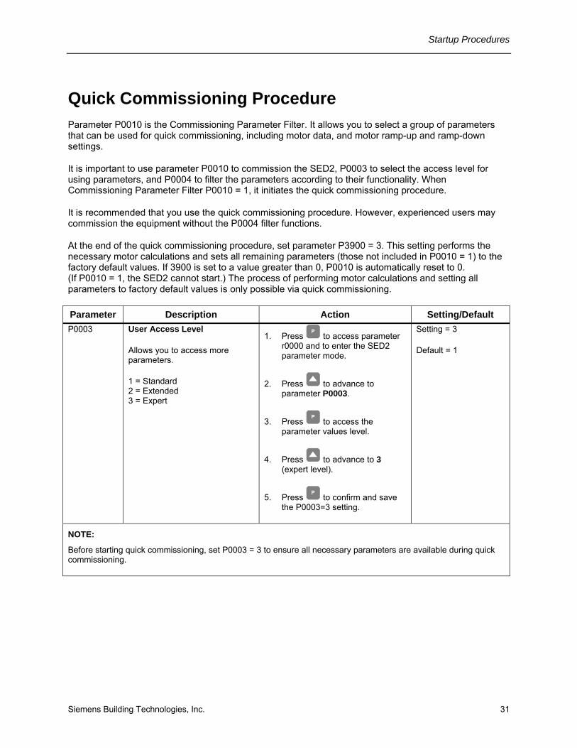
Quick Commissioning Procedure Parameter P0010 is the Commissioning Parameter Filter. It allows you to select a group of parameters that can be used for quick commissioning, including motor data, and motor ramp-up and ramp-down settings.
It is important to use parameter P0010 to commission the SED2, P0003 to select the access level for using parameters, and P0004 to filter the parameters according to their functionality. When Commissioning Parameter Filter P0010 = 1, it initiates the quick commissioning procedure.
It is recommended that you use the quick commissioning procedure. However, experienced users may commission the equipment without the P0004 filter functions.
At the end of the quick commissioning procedure, set parameter P3900 = 3. This setting performs the necessary motor calculations and sets all remaining parameters (those not included in P0010 = 1) to the factory default values. If 3900 is set to a value greater than 0, P0010 is automatically reset to 0. (If P0010 = 1, the SED2 cannot start.) The process of performing motor calculations and setting all parameters to factory default values is only possible via quick commissioning.
Parameter Description Action Setting/Default P0003 User Access Level
Allows you to access more parameters.
1 = Standard 2 = Extended 3 = Expert
1. Press to access parameter r0000 and to enter the SED2 parameter mode.
2. Press to advance to parameter P0003.
3. Press to access the parameter values level.
4. Press to advance to 3 (expert level).
5. Press to confirm and save the P0003=3 setting.
Setting = 3
Default = 1
NOTE:
Before starting quick commissioning, set P0003 = 3 to ensure all necessary parameters are available during quick commissioning.

SED2 VFD NEMA Type 3R Bypass Operating Instructions
32 Siemens Building Technologies, Inc.
Parameter Description Action Setting/Default P0010 Quick Commissioning
0 = Ready to Run
1 = Quick Commissioning
30 = Factory Setting
1. Press to access parameter r0000 and to enter the SED2 parameter mode.
2. Repeatedly press to advance to parameter P0010.
3. Press to access the parameter values level.
4. Press to advance to 1.
5. Press to confirm and save the P0010=1 setting.
Setting = 1
Default = 0
NOTES:
1. P0010 must always be set back to 0 before operating the motor.
2. If P3900 is greater than 0 on completion of commissioning, P0010 is automatically set back to 0.
P0100 Operation for Europe/N. America
0 = 50 Hz, kW (Europe) factory default
1 = 60 Hz, hp (North America)
2 = 60 Hz, kW (North America)
The setting of Motor Frequency and Unit of Measurement DIP switch 2 overrides P0100 settings 0 and 1.
1. Press to advance to parameter P0100.
2 Press to access the parameter values level.
3. Press to advance to 1.
4. Press to confirm and save the P0100 = 1 setting.
Setting = 1
Default = 0 or 1
(Default is determined by the setting of the motor frequency and unit of measurement DIP switches.)
NOTES:
1. Stop the SED2 (that is, disable all pulses) before changing this parameter.
2. Changing P0100 resets all rated motor parameters as well as other parameters that depend on the rated motor parameters (such as P0340, Calculation of motor Parameters).

Startup Procedures
Siemens Building Technologies, Inc. 33
Parameter Description Action Setting/Default P0304* Rated Motor Voltage
10V to 2000V.
Rated motor voltage (V) from motor nameplate.
1. Press to advance to parameter P0304.
2. Press to access the parameter values level.
3. Press to advance to nominal voltage.
4. Press to confirm and save the setting.
Setting = Motor nameplate
Default = Varies by model
P0305* Rated Motor Current
0A to 10,000A.
Rated motor current (A) from motor nameplate.
1. Press to advance to parameter P0305.
2. Press to access the parameter values level.
3. Press to advance to nominal current.
4. Press to confirm and save the setting.
Setting = Motor nameplate
Default = Varies by model
P0307* Rated Motor Power
0 kW or hp to 200 kW or hp.
Rated motor power (kW or hp) from motor nameplate.
If P0100 =1 (60 Hz, hp, North America), then motor power is in hp.
1. Press to advance to parameter P0307.
2. Press to access the parameter values level.
3. Press to advance to nominal power.
4. Press to confirm and save the setting.
Setting = Motor nameplate
Default = Varies by model (hp/voltage dependent)
* Motor related parameters.

SED2 VFD NEMA Type 3R Bypass Operating Instructions
34 Siemens Building Technologies, Inc.
Parameter Description Action Setting/Default P0308*, or P0309
Rated Motor cosPhi (P308), or Rated Motor Efficiency (P0309)
0.000 to 1.00 (P0308) or 0.0 to 99.9 (P0309)
Rated motor cosPhi or motor efficiency from motor nameplate.
If P0100 = 2 and P0307 = kW, P0308 displays;
If P0100 = 1 and P0307 = hp, P0309 displays.
P0309 = 100% corresponds to super conducting.
NOTE: This parameter is available when P0003 = 3 and P0010 = 1.
1. Press to advance to parameter P0308 or P0309.
2 Press to access the parameter values level.
3. Press to advance to nominal cosPhi or motor efficiency.
4. Press to confirm and save the setting.
Setting = Motor nameplate
P0308 Default = 0.00
P0309 Default = Varies by model (hp/voltage dependent)
P0310* Rated Motor Frequency
12 Hz to 650 Hz
Rated motor frequency (Hz) from motor nameplate.
Pole pair number is recalculated automatically if the parameter is changed.
1. Press to advance to parameter P0310.
2. Press to access the parameter values level.
3. Press to advance to nominal frequency (60 Hz).
4. Press to confirm and save the setting.
Setting = Motor nameplate 60 Hz
Default = 50 Hz/60 Hz
Default is dependent on the setting of the motor frequency and unit of measurement DIP switches.
* Motor related parameters.

Startup Procedures
Siemens Building Technologies, Inc. 35
Parameter Description Action Setting/Default P0311* Rated Motor Speed
0 to 40,000 1/min
Rated motor speed (rpm) from motor nameplate.
A setting of 0 causes an internal calculation of this value.
Vector control and V/f control with speed controller require this value.
Slip compensation in V/f control requires this value for correct operation.
Pole pair number is recalculated automatically if the parameter is changed.
1. Press to advance to parameter P0311.
2. Press to access the parameter values level.
3 Press to advance to nominal motor speed.
4. Press to confirm and save the setting.
Setting = Motor nameplate
Default = Varies by model
P0640 Motor Overload Factor
10% to 400%
Limited to the maximum SED2 output current rating, or to 400% of the rated current (P0305), whichever is lower.
NOTE: This parameter is available when P0003 = 3 and P0010 = 1
1. Press to advance to parameter P0640.
2. Press to access the parameter values level.
3. Press to advance to desired value.
4. Press to confirm and save the setting.
Setting = As applicable
Default = 110
* Motor related parameters.
SED2 VFD NEMA Type 3R Bypass Operating Instructions
36 Siemens Building Technologies, Inc.
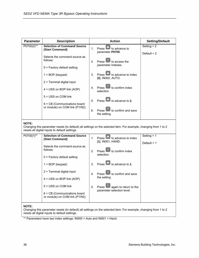
Parameter Description Action Setting/Default P0700(0)** Selection of Command Source
(Start Command)
Selects the command source as follows:
0 = Factory default setting
1 = BOP (keypad)
2 = Terminal digital input
4 = USS on BOP link (AOP)
5 = USS on COM link
6 = CB (Communications board or module) on COM link (P1/N2)
1. Press to advance to parameter P0700.
2. Press to access the parameter indexes.
3. Press to advance to index [0], IN000, AUTO.
4. Press to confirm index selection.
5. Press to advance to 2.
6. Press to confirm and save the setting.
Setting = 2
Default = 2
NOTE: Changing this parameter resets (to default) all settings on the selected item. For example, changing from 1 to 2 resets all digital inputs to default settings.
P0700[1]** Selection of Command Source (Start Command)
Selects the command source as follows:
0 = Factory default setting
1 = BOP (keypad)
2 = Terminal digital input
4 = USS on BOP link (AOP)
5 = USS on COM link
6 = CB (Communications board or module) on COM link (P1/N2)
1. Press to advance to index [1], IN001, HAND.
2. Press to confirm index selection.
3. Press to advance to 1.
4. Press to confirm and save the setting.
5. Press again to return to the parameter selection level.
Setting = 1
Default = 1
NOTE: Changing this parameter resets (to default) all settings on the selected item. For example, changing from 1 to 2 resets all digital inputs to default settings.
** Parameters have two index settings: IN000 = Auto and IN001 = Hand.

Startup Procedures
Siemens Building Technologies, Inc. 37
Parameter Description Action Setting/Default P1000[0]** Selection of Frequency
Setpoint
(Speed Command Source)
Selects the frequency setpoint source as follows:
1 = Motor potentiometer setpoint/BOP (keypad)
2 = Analog input
3 = Fixed frequency setpoint
4 = USS on BOP Link/AOP
5 = USS on COM link
6 = CB (Communications board or module) on COM link/P1-N2 communications
1. Press to advance to parameter P1000.
2. Press to access the parameter indexes.
3. Press to advance to index [0], IN000, AUTO.
4 Press to confirm index selection.
5. Press to advance to 2.
6. Press to confirm and save the setting.
Setting = 2
Default = 2
P1000[1]** Selection of Frequency Setpoint
(Speed Command Source)
Selects the frequency setpoint source as follows:
1 = Motor potentiometer setpoint/AOP
2 = Analog input
3 = Fixed frequency
4 = USS on BOP Link/AOP
5 = USS on COM link
6 = CB (Communications board or module) on COM link/P1-N2 communications
1. Press to advance to index [1], IN001, HAND.
2. Press to confirm index selection.
3. Press to advance to 1.
4. Press to confirm and save the setting.
5. Press again to return to the parameter selection level.
Setting = 1
Default = 1
** Parameters have two index settings: IN000 = Auto and IN001 = Hand.
SED2 VFD NEMA Type 3R Bypass Operating Instructions
38 Siemens Building Technologies, Inc.
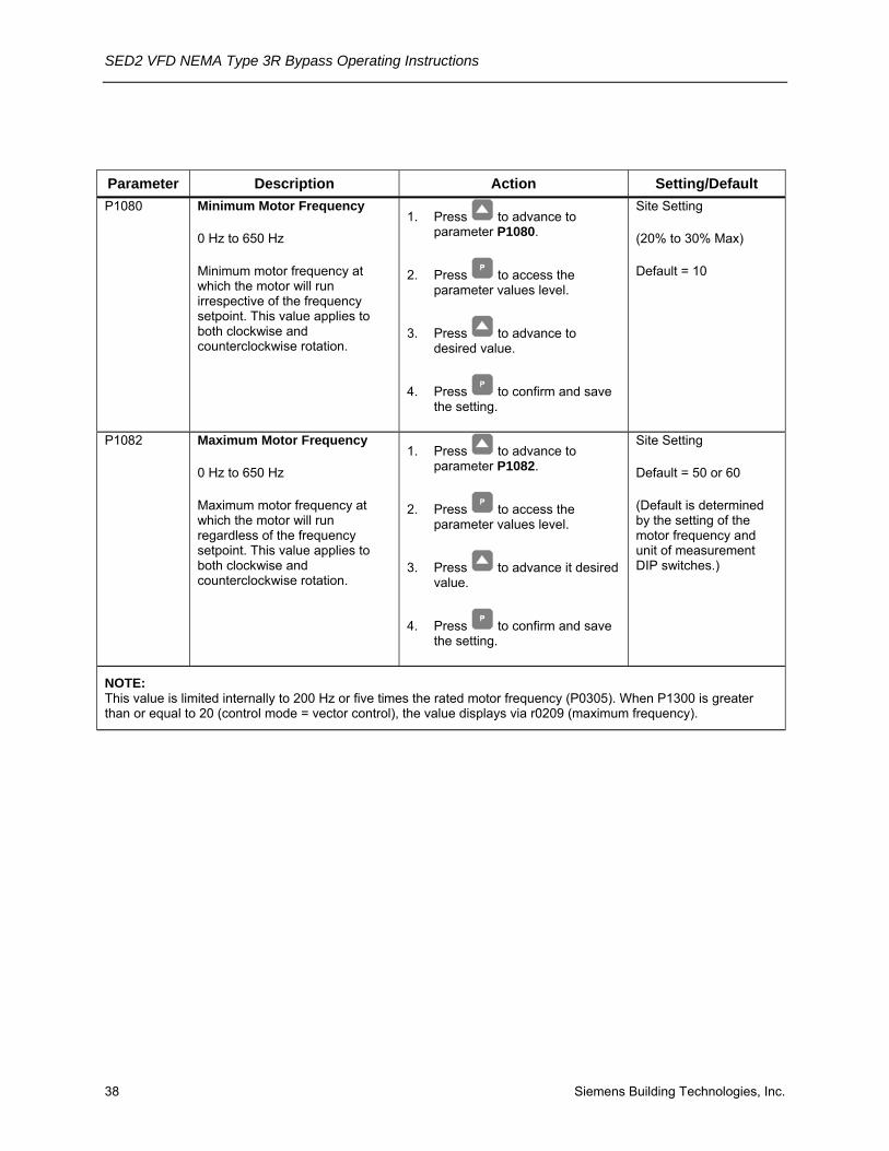
Parameter Description Action Setting/Default P1080 Minimum Motor Frequency
0 Hz to 650 Hz
Minimum motor frequency at which the motor will run irrespective of the frequency setpoint. This value applies to both clockwise and counterclockwise rotation.
1. Press to advance to parameter P1080.
2. Press to access the parameter values level.
3. Press to advance to desired value.
4. Press to confirm and save the setting.
Site Setting
(20% to 30% Max)
Default = 10
P1082 Maximum Motor Frequency
0 Hz to 650 Hz
Maximum motor frequency at which the motor will run regardless of the frequency setpoint. This value applies to both clockwise and counterclockwise rotation.
1. Press to advance to parameter P1082.
2. Press to access the parameter values level.
3. Press to advance it desired value.
4. Press to confirm and save the setting.
Site Setting
Default = 50 or 60
(Default is determined by the setting of the motor frequency and unit of measurement DIP switches.)
NOTE: This value is limited internally to 200 Hz or five times the rated motor frequency (P0305). When P1300 is greater than or equal to 20 (control mode = vector control), the value displays via r0209 (maximum frequency).
Startup Procedures
Siemens Building Technologies, Inc. 39
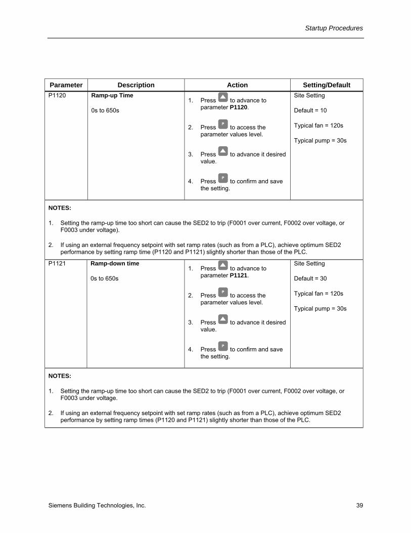
Parameter Description Action Setting/Default P1120 Ramp-up Time
0s to 650s 1. Press to advance to
parameter P1120.
2. Press to access the parameter values level.
3. Press to advance it desired value.
4. Press to confirm and save the setting.
Site Setting
Default = 10
Typical fan = 120s
Typical pump = 30s
NOTES:
1. Setting the ramp-up time too short can cause the SED2 to trip (F0001 over current, F0002 over voltage, or F0003 under voltage).
2. If using an external frequency setpoint with set ramp rates (such as from a PLC), achieve optimum SED2 performance by setting ramp time (P1120 and P1121) slightly shorter than those of the PLC.
P1121 Ramp-down time
0s to 650s 1. Press to advance to
parameter P1121.
2. Press to access the parameter values level.
3. Press to advance it desired value.
4. Press to confirm and save the setting.
Site Setting
Default = 30
Typical fan = 120s
Typical pump = 30s
NOTES:
1. Setting the ramp-up time too short can cause the SED2 to trip (F0001 over current, F0002 over voltage, or F0003 under voltage.
2. If using an external frequency setpoint with set ramp rates (such as from a PLC), achieve optimum SED2 performance by setting ramp times (P1120 and P1121) slightly shorter than those of the PLC.
SED2 VFD NEMA Type 3R Bypass Operating Instructions
40 Siemens Building Technologies, Inc.
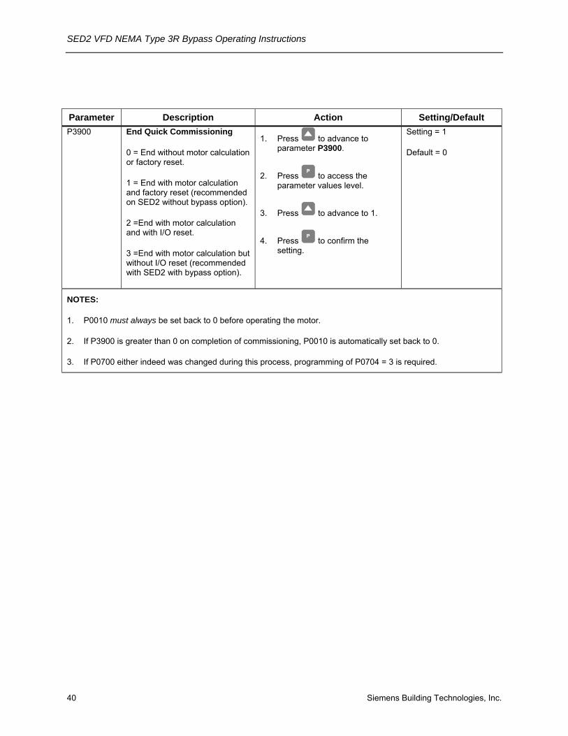
Parameter Description Action Setting/Default P3900 End Quick Commissioning
0 = End without motor calculation or factory reset.
1 = End with motor calculation and factory reset (recommended on SED2 without bypass option).
2 =End with motor calculation and with I/O reset.
3 =End with motor calculation but without I/O reset (recommended with SED2 with bypass option).
1. Press to advance to parameter P3900.
2. Press to access the parameter values level.
3. Press to advance to 1.
4. Press to confirm the setting.
Setting = 1
Default = 0
NOTES:
1. P0010 must always be set back to 0 before operating the motor.
2. If P3900 is greater than 0 on completion of commissioning, P0010 is automatically set back to 0.
3. If P0700 either indeed was changed during this process, programming of P0704 = 3 is required.

Startup Procedures
Siemens Building Technologies, Inc. 41
Additional Parameter Settings
NOTE: If Display Selection for r0000, parameter P0005=21 (actual frequency), then the BOP display alternately shows setpoint values and the actual value (0 Hz).
Flying Start Parameter Description Action Setting/Default P1200 Flying Start
Starts SED2 into a spinning motor by rapidly changing the output frequency of the SED2 until the actual motor speed is found. Then, the motor runs up to setpoint using the normal ramp time.
0 = Flying start disabled. 1 = Flying start is always active, start in direction of setpoint. 2 = Flying start is active, if power on, fault, OFF2, start in direction of setpoint. 3 = Flying start is active if fault, OFF2, start in direction of setpoint. 4 = Flying start is always active, only in direction of setpoint. 5 = Flying start is active if power on, fault, OFF2, only in direction of setpoint. 6 = Flying start is active if fault, OFF2, only in direction of setpoint.
1. Press to enter the SED2 parameter mode and to r0000.
2. Press to advance to parameter P1200.
3. Press to access the parameter values level.
4. Press to advance to desired setting.
5. Press to confirm and save the setting.
Minimum = 0 Default = 0 Maximum = 6
Suggested = 2
NOTES:
1. Flying start is useful for motors with high inertia loads.
2. Settings 1 through 3 search in both directions. Settings 4 through 6 search only in the direction of the setpoint.
3. Flying start must be used in cases where the motor may still be turning (such as after a brief input power break) or can be driven by the load. Otherwise, overcurrent trips occur.
4. If the SED2 faults on F0002 (overvoltage) on a start command, flying start may have to be optimized by reducing the values in P1203 and P1202.

SED2 VFD NEMA Type 3R Bypass Operating Instructions
42 Siemens Building Technologies, Inc.
Parameter Description Action Setting/Default P1202 Motor Current: Flying Start
Defines search current used for flying start. Value is in % based on the rated motor current (P0305)
1. Press to enter the SED2 parameter mode and to r0000.
2. Press to advance to parameter P1202.
3. Press to access the parameter values level.
4. Press to advance to desired value.
5. Press to confirm and save the setting.
Minimum = 10 Default = 100 Maximum = 200
NOTE:
Reducing the search current may improve performance for flying start if the inertia of the system is not very high.
P1203 Search Rate: Flying Start
Sets factor by which the output frequency changes during flying start to synchronize with the turning motor. This value, entered in % relative to the default time factor, defines the initial gradient and influences the time taken to search for the motor frequency.
The search time is the time taken to search through all frequencies between f_max + 2 x f_slip to 0 Hz.
1. Press to enter the SED2 parameter mode and to r0000.
2. Press to advance to parameter P1203.
3. Press to access the parameter values level.
4. Press to advance to desired value.
5. Press to confirm and save the setting.
Minimum = 10 Default = 100 Maximum = 200
NOTES:
1. P1203=100% is defined as giving a rate of 2% of f_slip, nom/ms.
2. P1203=200% would result in a rate of frequency change of 1% of f_slip, nom/ms.
3. A higher value produces a flatter gradient, and thus a longer search time. A lower value has the opposite effect.

Startup Procedures
Siemens Building Technologies, Inc. 43
Automatic Restart
CAUTION: Settings 2 through 5 can cause the motor to restart unexpectedly.
Parameter Description Action Setting/Default P1210 Automatic Restart
Enables SED2 restart after a supply power break or after a fault.
0 = Disabled. . 1 = Trip reset after power on (P1211 disabled). 2 = Restart after supply power blackout (P1211 disabled). 3 = Restart after brownout or fault (P1211 enabled). 4 = Restart after supply power brownout (P1211 disabled). 5 = Restart after blackout or fault (P1211 disabled).
1. Press to enter the SED2 parameter mode and to r0000.
2. Press to advance to parameter P1210.
3. Press to access the parameter values level.
4. Press to advance to desired setting.
5. Press to confirm and save the setting.
Minimum = 0 Default = 1 Maximum = 5
Suggested = 3
NOTES:
1. Auto restart requires a constant ON command (such as via a digital input).
2. P1200 flying start must be used in cases where the motor may still be turning, such as after a brief input power break, or can be driven by the load.
3. A supply power brownout is when the power is interrupted and reapplied before the operator panel display has gone dark. It is a very short supply power break where the DC link has not fully collapsed.
4. A supply power blackout is when the operator panel display has gone dark before the power is reapplied. It is a long supply power break where the DC link has fully collapsed.

SED2 VFD NEMA Type 3R Bypass Operating Instructions
44 Siemens Building Technologies, Inc.
Parameter Description Action Setting/Default P1211 Number of Restart Attempts
Specifies the number of times SED2 will attempt to restart after supply power brownout or fault, if P1210 automatic restart is activated.
1. Press to enter the SED2 parameter mode and to r0000.
2. Press to advance to parameter P1211.
3. Press to access the parameter values level.
4. Press to advance to desired value.
5. Press to confirm and save the setting.
Minimum = 0 Default = 3 Maximum = 10
Suggested = 10
P1212 Time to First Restart
Selects the time (seconds) before the SED2 is restarted for the first time if P1210 automatic restart is activated.
1. Press to enter the SED2 parameter mode and to r0000.
2. Press to advance to parameter P1212.
3. Press to access the parameter values level.
4. Press to advance to desired value.
5. Press to confirm and save the setting.
Minimum = 0 Default = 3 Maximum = 10
Suggested = 10

Startup Procedures
Siemens Building Technologies, Inc. 45
Parameter Description Action Setting/Default P1213 Restart Time Increment
Selects the amount (seconds) that the restart time is incremented for each restart of the SED2 if P1210 automatic restart is activated.
1. Press to enter the SED2 parameter mode and to r0000.
2. Press to advance to parameter P1213.
3. Press to access the parameter values level.
4. Press to advance to desired value.
5. Press to confirm and save the setting.
Minimum = 0 Default = 30 Maximum = 1000
Suggested = 10
Vdc Controller Parameter Description Action Setting/Default P1240 Configuration of Vdc
Controller
Enables/disabled Vdc controller.
The Vdc controller dynamically controls the DC link voltage to prevent overvoltage trips on high inertia systems.
Vdc-max automatically increases ramp-down times to keep the DC link voltage (r0026) within limits.
0 = Vdc controller disabled 1 = Vdc-max controller enabled 2 = Reserved 3 = Reserved
1. Press to enter the SED2 parameter mode and to r0000.
2. Press to advance to parameter P1240.
3. Press to access the parameter values level.
4. Press to advance to desired value.
5. Press to confirm and save the setting.
Minimum = 0 Default = 1 Maximum = 3

SED2 VFD NEMA Type 3R Bypass Operating Instructions
46 Siemens Building Technologies, Inc.
Pulse Frequency Parameter Description Action Setting/Default P1800 Pulse Frequency
Sets pulse frequency (kHz) of power switches in SED2. The frequency can be changed in increments of 2 kHz.
Pulse frequencies > 4 kHz selected on 380V to 480V units reduce the maximum continuous motor current.
1. Press to enter the SED2 parameter mode and to r0000.
2. Press to advance to parameter P1800.
3. Press to access the parameter values level.
4. Press to advance to desired value.
5. Press to confirm and save the setting.
Minimum = 2 Default = Varies by model (hp/voltage dependent) Maximum = 16
NOTES:
1. Minimum pulse frequency depends on P1082 (maximum frequency) and P0310 (rated motor frequency).
2. At 4 kHz, full output current is obtained up to 50 degrees C (CT mode); over 50 degrees C, full output may be obtained at 8 kHz.
3. If silent operation is not absolutely necessary, lower pulse frequencies may be selected to reduce SED2 losses and radio-frequency emissions.
4. Under certain circumstances, the SED2 may reduce the switching frequency to provide protection against over-temperature.

Startup Procedures
Siemens Building Technologies, Inc. 47
Reset to Factory Defaults Parameter Description Action Setting/Default P0010 P0970
Reset to Factory Default
Resets SED2 parameters to the factory defaults.
1. Press to enter the SED2 parameter mode and to r0000.
2. Press to advance to parameter P0010.
3. Press to access the parameter values level.
4. Press to advance to 30.
5. Press to confirm and save the setting.
6. Press to go to parameter P0970.
7. Press to access the parameter values level.
8. Press to advance to 1.
9. Press to confirm and save the setting.
P0010: Setting = 30 Default = 0
P0970: Setting = 1 Default = 0
NOTES:
1. First set P0010=30.
2. Stop SED2 (that is, disable all pulses) before you reset parameters to factory default values.
3. The following parameters retain their values after a factory reset:
• P0918 (address of CB, communications board or module)
• P2010 (USS baud rate)
• P2011 (USS address)
4. The reset process takes about 10 seconds.
SED2 VFD NEMA Type 3R Bypass Operating Instructions
48 Siemens Building Technologies, Inc.
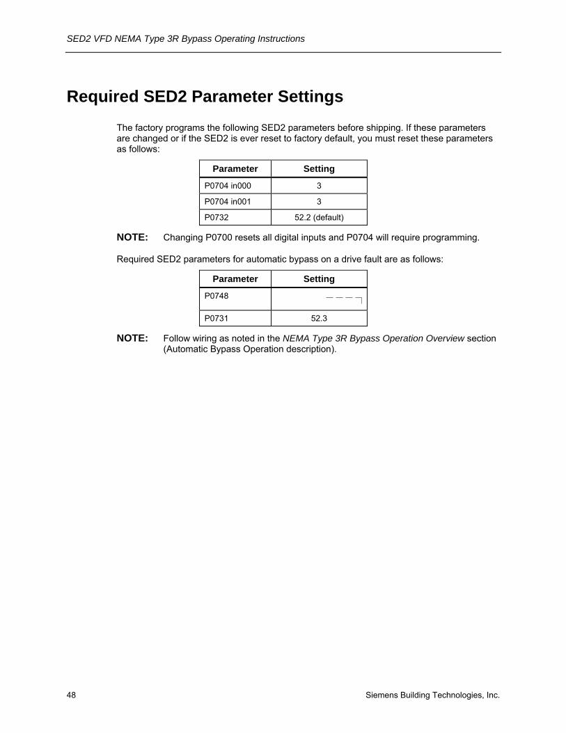
Required SED2 Parameter Settings The factory programs the following SED2 parameters before shipping. If these parameters are changed or if the SED2 is ever reset to factory default, you must reset these parameters as follows:
Parameter Setting
P0704 in000 3
P0704 in001 3
P0732 52.2 (default)
NOTE: Changing P0700 resets all digital inputs and P0704 will require programming.
Required SED2 parameters for automatic bypass on a drive fault are as follows:
Parameter Setting
P0748
P0731 52.3
NOTE: Follow wiring as noted in the NEMA Type 3R Bypass Operation Overview section (Automatic Bypass Operation description).
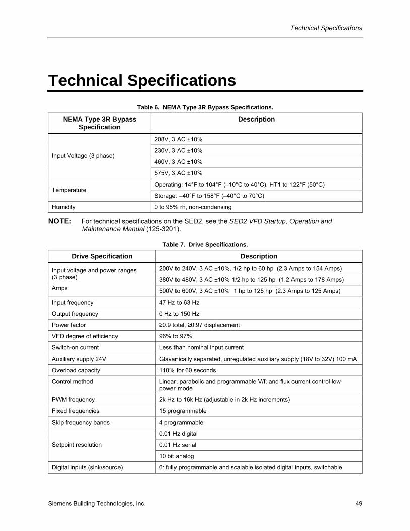
Technical Specifications
Siemens Building Technologies, Inc. 49
Technical Specifications Table 6. NEMA Type 3R Bypass Specifications.
NEMA Type 3R Bypass Specification
Description
208V, 3 AC ±10%
230V, 3 AC ±10%
460V, 3 AC ±10% Input Voltage (3 phase)
575V, 3 AC ±10%
Operating: 14°F to 104°F (–10°C to 40°C), HT1 to 122°F (50°C) Temperature
Storage: –40°F to 158°F (–40°C to 70°C)
Humidity 0 to 95% rh, non-condensing
NOTE: For technical specifications on the SED2, see the SED2 VFD Startup, Operation and Maintenance Manual (125-3201).
Table 7. Drive Specifications.
Drive Specification Description
200V to 240V, 3 AC ±10%. 1/2 hp to 60 hp (2.3 Amps to 154 Amps)
380V to 480V, 3 AC ±10% 1/2 hp to 125 hp (1.2 Amps to 178 Amps) Input voltage and power ranges (3 phase)
Amps 500V to 600V, 3 AC ±10% 1 hp to 125 hp (2.3 Amps to 125 Amps)
Input frequency 47 Hz to 63 Hz
Output frequency 0 Hz to 150 Hz
Power factor ≥0.9 total, ≥0.97 displacement
VFD degree of efficiency 96% to 97%
Switch-on current Less than nominal input current
Auxiliary supply 24V Glavanically separated, unregulated auxiliary supply (18V to 32V) 100 mA
Overload capacity 110% for 60 seconds
Control method Linear, parabolic and programmable V/f; and flux current control low-power mode
PWM frequency 2k Hz to 16k Hz (adjustable in 2k Hz increments)
Fixed frequencies 15 programmable
Skip frequency bands 4 programmable
0.01 Hz digital
0.01 Hz serial Setpoint resolution
10 bit analog
Digital inputs (sink/source) 6: fully programmable and scalable isolated digital inputs, switchable

SED2 VFD NEMA Type 3R Bypass Operating Instructions
50 Siemens Building Technologies, Inc.
Drive Specification Description
Analog inputs 2: 0 to 10 Vdc, 0/4 mA to 20 mA , can also be configured as digital inputs or Ni 1000 input
Relay outputs 2: configurable 30 Vdc/5A (resistive), 250 Vac 2A (inductive)
Analog outputs 2: programmable (0/4 mA to 20 mA or 0V to 10 Vdc)
Serial interface RS-485; Protocols: Siemens, P1 and Johnson, N2; Transmission rate: Up to 38.4k baud
IP20: NEMA Type 1 (with protective shield and gland plate installed) Protection level
IP54: NEMA Type 12 (400V and 500V series only)
Operating: 14°F to 104°F (–10°C to 40°C) Temperature ranges
Storage: –40°F to 158°F (–40°C to 70°C)
Humidity 95% rh, non-condensing
Operational altitudes Up to 3280 ft (1000 m) above sea level without de-rating
• Under-voltage
• Over-voltage
• Overload
• Ground fault
• Short circuit
• Stall prevention
• Locked motor
• Motor over temperature l2 t, PTC
• Over-temperature
Protection features
• Parameter PIN protection
Standards UL, cUL
CE conformity Conformity with EC Low Voltage Directive 73/23/EEC
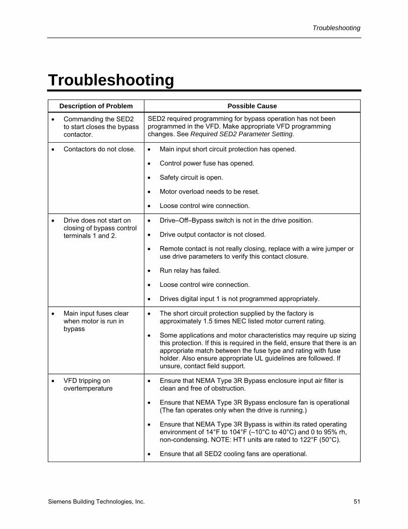
Troubleshooting
Siemens Building Technologies, Inc. 51
Troubleshooting Description of Problem Possible Cause
• Commanding the SED2 to start closes the bypass contactor.
SED2 required programming for bypass operation has not been programmed in the VFD. Make appropriate VFD programming changes. See Required SED2 Parameter Setting.
• Contactors do not close. • Main input short circuit protection has opened.
• Control power fuse has opened.
• Safety circuit is open.
• Motor overload needs to be reset.
• Loose control wire connection.
• Drive does not start on closing of bypass control terminals 1 and 2.
• Drive–Off–Bypass switch is not in the drive position.
• Drive output contactor is not closed.
• Remote contact is not really closing, replace with a wire jumper or use drive parameters to verify this contact closure.
• Run relay has failed.
• Loose control wire connection.
• Drives digital input 1 is not programmed appropriately.
• Main input fuses clear when motor is run in bypass
• The short circuit protection supplied by the factory is approximately 1.5 times NEC listed motor current rating.
• Some applications and motor characteristics may require up sizing this protection. If this is required in the field, ensure that there is an appropriate match between the fuse type and rating with fuse holder. Also ensure appropriate UL guidelines are followed. If unsure, contact field support.
• VFD tripping on overtemperature
• Ensure that NEMA Type 3R Bypass enclosure input air filter is clean and free of obstruction.
• Ensure that NEMA Type 3R Bypass enclosure fan is operational (The fan operates only when the drive is running.)
• Ensure that NEMA Type 3R Bypass is within its rated operating environment of 14°F to 104°F (–10°C to 40°C) and 0 to 95% rh, non-condensing. NOTE: HT1 units are rated to 122°F (50°C).
• Ensure that all SED2 cooling fans are operational.

SED2 VFD NEMA Type 3R Bypass Operating Instructions
52 Siemens Building Technologies, Inc.
Fuses Verify that 120 Vac power is available on the secondary side of the power transformer. If power is not proper, check the Bypass components, such as:
• Power transformer
• Power transformer fuses (F1, F2, and F3). Table 8 provides fuse replacement information.
Table 8. Fuse Replacement Information.
NEMA Type 3R Bypass Enclosure ABC 250 VA Transformers
Voltage Primary Fuse (F1 and F2) Secondary Fuse (F3)
208V Bussmann/Littlefuse LP-CC-3.5 Bussmann/Littlefuse LP-CC-3.5
230V Bussmann/Littlefuse LP-CC-3.2 Bussmann/Littlefuse LP-CC-3.5
460V Bussmann/Littlefuse LP-CC-1.6 Bussmann/Littlefuse LP-CC-3.5
575V Bussmann/Littlefuse LP-CC-1.25 Bussmann/Littlefuse LP-CC-3.5
NEMA Type 3R Bypass Enclosure DE and F 750 VA Transformers
Voltage Primary Fuse (F1 and F2) Secondary Fuse (F3)
208V Bussmann/Littlefuse LP-CC-9 Bussmann/Littlefuse LP-CC-10
230V Bussmann/Littlefuse LP-CC-8 Bussmann/Littlefuse LP-CC-10
460V Bussmann/Littlefuse LP-CC-4.5 Bussmann/Littlefuse LP-CC-10
575V Bussmann/Littlefuse LP-CC-3.5 Bussmann/Littlefuse LP-CC-10
Troubleshooting
Siemens Building Technologies, Inc. 53

SED2 VFD NEMA Type 3R Bypass Operating Instructions
Siemens Building Technologies, Inc. 1000 Deerfield Parkway Buffalo Grove, IL 60089-4513 Tel: +1 847-215-1000 Fax +1 847-215-1093
Siemens Building Technologies, Ltd. 2 Kenview Blvd. Brampton, Ontario Canada L6T 5E4 Tel: +1 905-799-9937
www.sbt.siemens.com


