Security Systems Communication & Philips & Security...
70
Philips Communication & Security Systems
Transcript of Security Systems Communication & Philips & Security...

PhilipsCommunication &Security Systems
All round expertise
Philips leads the way with total solutions for
communications and security applications. Dedicated expertise in
access control, closed-circuit TV, congress, intercom, paging and
public address means even the most demanding requirements
can be met. Compability and flexibility are guaranteed by the
integrated system approach.
The high-quality products from Philips Communications
& Security Systems are backed up with comprehensive
maintenance, service and training support. And with a wealth of
experience in transport, industrial, commercial, healthcare, leisure
and retail applications, you can be sure that communications
channels will stay open, and personnel and property remain safe.
Dat
a su
bjec
t to
cha
nge
with
out
notic
e.
392
4 98
1 15
511
09/
97
©P
hilip
s E
lect
roni
cs N
.V.
1997
PhilipsCommunication &Security Systems
08704-intercom-oms.qxd 18-05-98 19:49 Side 1

Dokument1 18-05-98 20:50 Side 1

M100 Intercom & Nurse Call CatalogueTTable of contentsable of contents
3
© Philips Electronics N.V. 1997Data subject to change without notice. Printed in Norway.
M100 INTERCOM SYSTEM . . . . . . . . . . . . . . . . . . . . . . . . 4Introduction . . . . . . . . . . . . . . . . . . . . . . . . . . . . . . . . . 4Standard stations . . . . . . . . . . . . . . . . . . . . . . . . . . . . . 5Industrial stations . . . . . . . . . . . . . . . . . . . . . . . . . . . . . 8Heavy duty and explosion-proof stations . . . . . . . . . . .10Special stations . . . . . . . . . . . . . . . . . . . . . . . . . . . . . . .13Data - special stations . . . . . . . . . . . . . . . . . . . . . . . . . .14Station kits and coupler . . . . . . . . . . . . . . . . . . . . . . . .15Station accessories . . . . . . . . . . . . . . . . . . . . . . . . . . . . .18Station and accessory combinations . . . . . . . . . . . . . . .20Kit and accessory combinations . . . . . . . . . . . . . . . . . .21
M100 NURSE CALL SYSTEM . . . . . . . . . . . . . . . . . . . . . . .22System build-up and description . . . . . . . . . . . . . . . . .22Equipment and accessories . . . . . . . . . . . . . . . . . . . . . .24Technical data . . . . . . . . . . . . . . . . . . . . . . . . . . . . . . .30
M100 S-16/32 INTERCOM SYSTEM . . . . . . . . . . . . .32Introduction . . . . . . . . . . . . . . . . . . . . . . . . . . . . . . . . .32Function description . . . . . . . . . . . . . . . . . . . . . . . . . .33Exchange . . . . . . . . . . . . . . . . . . . . . . . . . . . . . . . . . . .34Starter packs . . . . . . . . . . . . . . . . . . . . . . . . . . . . . . . . .35Exchange accessories . . . . . . . . . . . . . . . . . . . . . . . . . . .36Software . . . . . . . . . . . . . . . . . . . . . . . . . . . . . . . . . . . .37
M100 S-72 EXCHANGE FAMILY RANGE . . . . . . . . .38Introduction . . . . . . . . . . . . . . . . . . . . . . . . . . . . . . . . .38Function description . . . . . . . . . . . . . . . . . . . . . . . . . .39Standard software function packages . . . . . . . . . . . . . .41How to build a complete exchange . . . . . . . . . . . . . . .42
M100 SB-80 Basic function exchange . . . . . . . . . . . . . .43M100 Stand-alone exchanges . . . . . . . . . . . . . . . . . . . .44M100 S-72 Stand-alone exchanges . . . . . . . . . . . . . . . .45M100 SO-72 ODIN Network Exchanges . . . . . . . . . . .46Exchange expansion units and kits . . . . . . . . . . . . . . .50Line termination equipment, voice boardand line cards . . . . . . . . . . . . . . . . . . . . . . . . . . . . . . . .53Data interface and interconnection equipment . . . . . .54Couplers . . . . . . . . . . . . . . . . . . . . . . . . . . . . . . . . . . .55Optical Digital Information Network (ODIN) . . . . . .56
EXCHANGE CABINET CONFIGURATIONS . . . . .58System cabinets . . . . . . . . . . . . . . . . . . . . . . . . . . . . . . .58
PC PROGRAMS . . . . . . . . . . . . . . . . . . . . . . . . . . . . .59System maintenance program for Windows . . . . . . . . .59Basic call monitor program . . . . . . . . . . . . . . . . . . . . .60Nurse call program . . . . . . . . . . . . . . . . . . . . . . . . . . . .60
BI-WAY INTERCOM SYSTEM . . . . . . . . . . . . . . . . . .61Introduction . . . . . . . . . . . . . . . . . . . . . . . . . . . . . . . . .61Function description . . . . . . . . . . . . . . . . . . . . . . . . . .62Starter kit . . . . . . . . . . . . . . . . . . . . . . . . . . . . . . . . . . .63Optional accessories . . . . . . . . . . . . . . . . . . . . . . . . . . .64
STANDARD REQUIREMENT SPECIFICATION . . .65
IP DEGREE OF PROTECTION . . . . . . . . . . . . . . . . .66
TYPENUMBER SURVEY . . . . . . . . . . . . . . . . . . . . . .67

4
IntroduIntroductionction
Modern, advanced communication systems are designed to simplify contactbetween individuals in business and indus-trial environments as well as in public ser-vice institutions and health care. By doing so they help achieve greater effi-ciency and effectiveness in everyday opera-tions. They also contribute to higher standardsof performance and security.
The resourceful way of achieving theseaims... the flexible way... is investing in aPhilips M100 Intercom System.
The efficient and versatile concept thatnot only provides the means for people tocommunicate but also the facilities tostore and recall information when needed.
In addition, M100 provides the means forintegration with other systems and equip-ment in the CSS product range to therebyachieve the optimum level of safety andsecurity for any premises.
Whatever the installation... a large hospital or an industrial complex... a smalloffice or local garage which may only needa couple of intercom stations... withPhilips� M100 a tailormade installation isassured to meet any demand - precisely.
Being a worldwide organization, Philipscan draw upon market information fromalmost 100 countries across five continents. Highly specialized engineers in the
CSS Supply Centre, Oslo utilize this vastamount of user�s knowledge.
This, combined with the advanced technological environment in Scandinavia, resulted in the developmentand production of leading internal com-munication systems.
For every project that you become involvedin you can rest assured that our personnelare always there as your support - for
advice and help - whatever your require-ments.
Philips' customer support does not stopwith the supply of new equipment.
After-sales service embraces bothprofessional engineering skills as well assales of spare parts and customer backup.
Important:Illustrations in this catalogue show the products with or without different options. Options are not necessarily included in the type number for each product and will not automatically be delivered as part of the product.See description for each product and tables for accessories and kits.
M100 Intercom System

5
Standard stationsStandard stations
LBB 7089/10 Desktop master station
The desktop master station is designed fordesktop use in office-like environments.The station cabinet is made in light greyABS plastic for desk top or wall mounting.
Controls for volume adjustment, simplexmode, privacy and system functions.
+/- buttons for accepting and rejecting certain functions. A call tone and a pilotlamp indicate connection.A handset may be connected to providelowspeaking conversation.
LBB 7089/15 Compact master station
The compact master station has the samefunctional use as the desktop master station but is intended for areas and applications where compactness is ofimportance and where there is a requirement for surface or flush mountingin desk or wall. A handset with cradle may be connectedfor lowspeaking conversation.
A flush mount frame is available whichenables the compact master station to beused in flush mount applications such ascontrol desks and in walls.
Technical data: LBB 7089/10 LBB 7089/15
Dimensions (wxhxd) in mm/inch: 164x75x212/6.5x3x8.3 93x65x224/3.7x2.6x8.8Weight, net, in kg/lb: 0.530/1.2 0.360/0.8Environmental conditions, category: T1 T1IP code: 40 (front access) 40 (front access)Approval: CE CESupply voltage : 36 V d.c. 36 V d.c.
At the station, idle <10 V d.c. <10 V d.c.At the station, in operation 18 - 36 V d.c. 18 - 36 V d.c.
Current consumptionAt the station, idle <0.3 mA <0.3 mAAt the station, in operation 25 - 38 mA 25 - 38 mA
Output power (continuous/peak): 90/300 mW 90/300 mW Cabling:
Extension line 2-wire 2-wire

LBB 7089/18 Compact master display station with back light
6
Standard stationsStandard stations
LBB 7089/16 Compact master display station
The station is identical to the compactmaster display station except that the dis-play has a built-in back light for improvedreadability. Extra back light power is needed whenused with the S-16 exchange.
Technical data: LBB 7089/16 LBB 7089/18
Dimensions (wxhxd) in mm/inch: 93x65x224/3.7x2.6x8.8 93x65x224/3.7x2.6x8.8Weight, net, in kg/lb: 0.420/0.9 0.420/0.9Environmental conditions, category: T1 T1IP code: 40 (front access) 40 (front access)Approval: CE CESupply voltage : 36 V d.c. 36 V d.c.
At the station, idle <10 V d.c. <10 V d.c.At the station, in operation 18 - 36 V d.c. 18 - 36 V d.c.Power line 24 - 40 V d.c. 24 - 40 V d.c.
Current consumptionAt the station, idle <0.3 mA <0.3 mAAt the station, in operation 25 - 38 mA 25 - 38 mA
Output power (continuous/peak): 90/300 mW 90/300 mW Cabling:
Extension line 2-wire 2-wire
The compact master display station isidentical to the compact master station butalso incorporates an LCD display.
This display has 2 lines of 16 characterseach for visual display of functions, direc-tory, called number and name, callingparty identification and a number of otherpossibilities in selected languages.
The information displayed has a logicalstructure where call information is pro-grammable.
For special applications see relevant soft-ware chapter. For general applications thefigure on right shows a typical displaystructure.

7
Standard stationsStandard stations
LBB 7089/31 Single call station
LBB 7089/32 Dual call station
The single call station is housed in a lightgrey ABS plastic cabinet for desktop orwall mounting and intended for indooruse. Ideal for use at doors or in lifts. Thestation can be used in connection with a CCTV camera system for remote observa-tion. Kits are available for increased out-put power and/or remote door opening.They must be powered separately.In operation the station allows for loud-speaking and handsfree conversation. Bypressing the call button outgoing calls aremade to one pre-programmed location. If the call is in indirect mode it has to beaccepted by the receiver before normalduplex conversation can be established. If an outgoing call is not answered withina pre-programmed time-frame, the call willautomatically be reset. Any station in thesystem can reach the single call station bykeying the station�s extension number.
The dual call station is identical to the single call station with the exception of thekeypad which is replaced by two call but-tons and a call cancel button. This means that the dual call station has the possibility to call two different pre-programmed locations in direct or indirectmode.
A call or call request can be terminated bypressing the cancel key on the station or, ifnot used, automatically after a pre-set time-frame.
Technical data: LBB 7089/31 LBB 7089/32
Dimensions (wxhxd) in mm/inch: 95x65x224/3.7x2.6x8.8 93x65x224/3.7x2.6x8.8Weight, net, in kg/lb: 0.330/0.7 0.330/0.7Environmental conditions, category: T1 T1IP code: 40 (front access) 40 (front access)Approval: CE CESupply voltage : 36 V d.c. 36 V d.c.
At the station, idle <10 V d.c. <10 V d.c.At the station, in operation 18 - 36 V d.c. 18 - 36 V d.c.
Current consumptionAt the station, idle <0.3 mA <0.3 mAAt the station, in operation 25 - 38 mA 25 - 38 mA
Output power (continuous/peak): 90/300 mW 90/300 mW Cabling:
Extension line 2-wire 2-wire

8
Industrial stationsIndustrial stations
LBB 7089/20 Industrial master station
LBB 7089/30Industrial master display station with back light
The industrial master station is designedfor use in light industrial environmentswhere there is a demand for flush or onwall mounting. If the latter is required, anoptional on-wall back box is necessary.
The station is delivered as a flush mountunit with a die-cast zink alloy front, lac-quered in grey. It has a built-in directorylist and a splash-proof membrane keypad.
Controls for simplex mode and systemfunctions, as well as +/- buttons for accept-ing and rejecting certain functions. Thevolume and privacy is internally pre-set ineach station. A call tone and a pilot lampindicate connection.
The industrial master display station isidentical to the industrial master stationbut also incorporates an LCD display witha back light for improved readability.
This display has 2 lines of 16 characterseach for visual display of functions, direc-tory, called number and name, callingparty identification and a number of otheruser-friendly features.
The information displayed has a logicalstructure where call information is pro-grammable.For special applications see relevant software chapter.
For general applications the figure aboveshows a typical display structure.
Extra back light power is needed whenused with the S-16 exchange.
Technical data: LBB 7089/20 LBB 7089/30
Dimensions (wxhxd) in mm/inch: 130x265x75/5.1x10.4x3 130x265x75/5.1x10.4x3 Weight, net, in kg/lb: 1.4/3 1.4/3Environmental conditions, category: T1 T1IP code: 40 (front access) 40 (front access)Approval: CE CESupply voltage : 36 V d.c. 36 V d.c.
At the station, idle <10 V d.c. <10 V d.c.At the station, in operation 18 - 36 V d.c. 18 - 36 V d.c.Power line 20 - 40 V d.c.
Current consumption:At the station, idle <0.3 mA <0.3 mAAt the station, in operation 25 - 38 mA 25 - 38 mA
Output power (continuous/peak): 90/300 mW 90/300 mW Cabling:
Extension line 2-wire 2-wire
9
Industrial stationsIndustrial stations
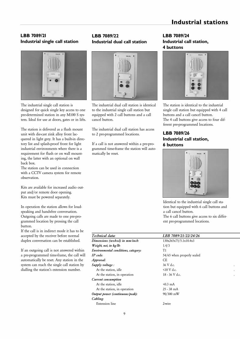
LBB 7089/21 Industrial single call station
LBB 7089/22 Industrial dual call station
LBB 7089/24 Industrial call station, 4 buttons
LBB 7089/26 Industrial call station, 6 buttons
The industrial single call station isdesigned for quick single key access to onepre-determined station in any M100 S sys-tem. Ideal for use at doors, gates or in lifts.
The station is delivered as a flush mountunit with die-cast zink alloy front lac-quered in light grey. It has a built-in direc-tory list and splash-proof front for lightindustrial environments where there is arequirement for flush or on wall mount-ing, the latter with an optional on wallback box.The station can be used in connectionwith a CCTV camera system for remoteobservation.
Kits are available for increased audio out-put and/or remote door opening.Kits must be powered separately.
In operation the station allows for loud-speaking and handsfree conversation.Outgoing calls are made to one pre-pro-grammed location by pressing the callbutton. If the call is in indirect mode it has to beaccepted by the receiver before normalduplex conversation can be established.
If an outgoing call is not answered withina pre-programmed time-frame, the call willautomatically be reset. Any station in thesystem can reach the single call station bydialling the station�s extension number.
The industrial dual call station is identicalto the industrial single call station butequipped with 2 call buttons and a callcancel button.
The industrial dual call station has accessto 2 pre-programmed locations.
If a call is not answered within a pre-pro-grammed time-frame the station will auto-matically be reset.
Technical data: LBB 7089/21/22/24/26Dimensions (wxhxd) in mm/inch: 130x265x75/5.1x10.4x3 Weight, net, in kg/lb: 1.4/3Environmental conditions, category: T1IP code: 54/65 when properly sealedApproval: CESupply voltage : 36 V d.c. .
At the station, idle <10 V d.c. .At the station, in operation 18 - 36 V d.c. .
Current consumptionAt the station, idle <0.3 mA At the station, in operation 25 - 38 mA
Output power (continuous/peak): 90/300 mWCabling:
Extension line 2-wire
The station is identical to the industrialsingle call station but equipped with 4 callbuttons and a call cancel button.The 4 call buttons give access to four dif-ferent pre-programmed locations.
Identical to the industrial single call sta-tion but equipped with 6 call buttons anda call cancel button.The 6 call buttons give access to six differ-ent pre-programmed locations.

10
HeaHeavvy duty duty and explosion-proof stationsy and explosion-proof stations
LBB 7089/40 Heavy duty master station
LBC 3490/10 Loudspeaker horn, 16 ohm
Front plate in blank aluminium enshroudspolyurethane elastomere sealing caps cover-ing the selection and function buttons.
Controls for simplex mode and systemfunctions. +/- buttons for accepting andrejecting certain functions.
Volume and privacy must be pre-set inter-nally in each station.A call tone and a pilot lamp indicate con-nection.
A heavy duty handset kit may be fitted foruse in noisy areas or for confidential calls.
External call signal may be renderedthrough separate bell or lamp giving a sig-nal in areas with high noise level.
The heavy duty master station has a built-in application kit as standard whichrequires external power either locally orcentrally.
When not used for external signallingthe application kit can be used for open-ing doors.
This 10 ½" x 7" speaker is designed for usewith the heavy duty master station eitheroutdoors or in industrial buildings andyards.
The horn is splash and dust-proof, madefrom aluminium, and is supplied with anadjustable mounting bracket.
Technical data: LBB 7089/40 LBC 3490/10
Dimensions (wxhxd) in mm/inch: 160x260x106/6.3x10.2x4.2 Weight, net, in kg/lb: 2.7/5.9Environmental conditions, category: T4IP code: 40 (front access)Approval: CESupply voltage : 36 V d.c.
At the station, idle <10 V d.c.At the station, in operation 24 - 40 V d.c./18 - 30 V a.c.
Current consumptionAt the station, idle <0.3 mA At the station, in operation 25 - 38 mAFrom unregulated 30 V power 350 mA average at 16 WFrom regulated 36 V power 800 mA max.
Output power (continuous/peak): 90/300 mWCabling:
Extension line 2-wire
The heavy duty master station is for use insevere indoor or outdoor applications.The station is especially designed for with-standing rigorous environments includingtemperature extremes and dusty or corro-sive atmospheres. Large keys provide for convenient opera-tion even when wearing protective gloves.
Built-in microphone and external loud-speaker horn enable maximum adaptationto the local acoustical situation.
The heavy duty master station is deliveredas a wall mount unit constructed fromcorrosion-proofed wide gauge aluminiumand with an orange colour finish.
Overall length: 276/10.91.25/2.8Rated impedance: 16 ohm65Eff. freq. range (-10dB): 410- 3900 HzPower handling capacity: 10 W
11
HeaHeavvy duty duty and explosion-proof stationsy and explosion-proof stations
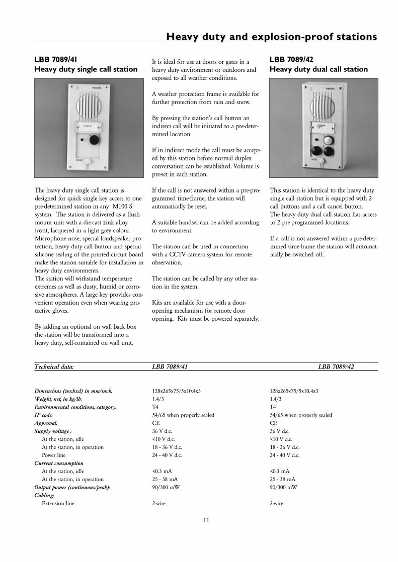
LBB 7089/41Heavy duty single call station
LBB 7089/42 Heavy duty dual call station
It is ideal for use at doors or gates in aheavy duty environment or outdoors andexposed to all weather conditions.
A weather protection frame is available forfurther protection from rain and snow.
By pressing the station�s call button anindirect call will be initiated to a pre-deter-mined location.
If in indirect mode the call must be accept-ed by this station before normal duplexconversation can be established. Volume ispre-set in each station.
If the call is not answered within a pre-pro-grammed time-frame, the station willautomatically be reset.
A suitable handset can be added accordingto environment.
The station can be used in connectionwith a CCTV camera system for remoteobservation.
The station can be called by any other sta-tion in the system.
Kits are available for use with a door-opening mechanism for remote dooropening. Kits must be powered separately.
This station is identical to the heavy dutysingle call station but is equipped with 2call buttons and a call cancel button. The heavy duty dual call station has accessto 2 pre-programmed locations.
If a call is not answered within a pre-deter-mined time-frame the station will automat-ically be switched off.
Technical data: LBB 7089/41 LBB 7089/42
Dimensions (wxhxd) in mm/inch: 128x265x75/5x10.4x3 128x265x75/5x10.4x3Weight, net, in kg/lb: 1.4/3 1.4/3Environmental conditions, category: T4 T4IP code: 54/65 when properly sealed 54/65 when properly sealedApproval: CE CESupply voltage : 36 V d.c. 36 V d.c.
At the station, idle <10 V d.c. <10 V d.c.At the station, in operation 18 - 36 V d.c. 18 - 36 V d.c.Power line 24 - 40 V d.c. 24 - 40 V d.c.
Current consumptionAt the station, idle <0.3 mA <0.3 mAAt the station, in operation 25 - 38 mA 25 - 38 mA
Output power (continuous/peak): 90/300 mW 90/300 mW Cabling:
Extension line 2-wire 2-wire
The heavy duty single call station isdesigned for quick single key access to onepre-determined station in any M100 S system. The station is delivered as a flushmount unit with a die-cast zink alloyfront, lacquered in a light grey colour.Microphone nose, special loudspeaker pro-tection, heavy duty call button and specialsilicone sealing of the printed circuit boardmake the station suitable for installation inheavy duty environments. The station will withstand temperatureextremes as well as dusty, humid or corro-sive atmospheres. A large key provides con-venient operation even when wearing pro-tective gloves.
By adding an optional on wall back boxthe station will be transformed into aheavy duty, self-contained on wall unit.

12
HeaHeavvy duty duty and explosion-proof stationsy and explosion-proof stations
Technical data: LBB 7089/50 LBB 7089/52
Dimensions (wxhxd) in mm/inch: 340x340x150/13.39x13.39x5.91 170x340x190/6.69x13.39x7.48Weight, net, in kg/lb: 10.1/22.2 6.4/14.1Environmental conditions, category: T5 T5
Classification EExed[ib]IIC T6 EExed[ib]IIC T6IP code: 66 66Supply voltage :
Line, idle 10 V d.c. 10 V d.c.Line, in operation 18-25 V d.c. 18-25 V d.c.Power line 18-36 V d.c. 18-36 V d.c.
Current consumptionLine, idle <0.3 mA <0.3 mA Line, in operation 25 - 38 mA 25 - 38 mAPower line 500 mA max. 500 mA max.
Output power (continuous/peak): 3.5 W/ 3.5 W/Cabling:
Extension line/Power line 2-wire/2-wire 2-wire/2-wire
Classification ExplanationEEx Explosion-proof apparatuse Increased safetyd Flame-proof enclosures[ib] Safety barrierII For use in places that are susceptible to fire/steam
other than minesC Gas group (Acetylene/Hydrogen)
T6 Maximum surface temperature = 85oC
The station is housed in a splash-proofdark grey cabinet for wall mounting. The cabinet is made of glass fibre re-inforced, self-extinguishing polyesterresin. All electronics are installed in aninner flame-proof box.The station operates in duplex with abuilt-in microphone and amplifier forhigh output to a flame-proof loud-speaker horn. The keyboard has largekeys for ease of operation.Controls for simplex mode and systemfunctions are identical to all other M100 S stations.Privacy and external volume controls arenot available.
LBB 7089/52 Explosion-proof dual callstation IIC
The station is housed in a double hous-ing for wall mounting and consists of aflame-proof box for the electronics and asplash-proof dark grey polyester box forthe keyboard and cabling.The keyboard/cabling box is made ofglassfibre reinforced, self-extinguishingpolyester resin. The station has access to 2 pre-definedlocations.
LBB 7071/10 Flame-proof loudspeakerhorn, 8 W/8 ohm
The heavy duty flame-proof loudspeakerhorn specially designed for use in areaswhere gasses or other explosives dictatespecial precautions. Suitable for use withexplosion-proof master stations.The loudspeaker is completely weather-proof, is resistant to salt-laden air andunaffected by most chemicals. Made incast silumin with grey epoxy finish.
Technical dataNominal impedance: 8 ohmRated power: 8 WFrequency range: 500-6000 HzProtection: IP 67Dimensions,front and depth: 124 x 110 mm
4.88 x 4.33 inNet weight: 1.5 kg, 3.3 lb
LBB 7089/50 Explosion-proof masterstation IIC
13
Special stationsSpecial stations
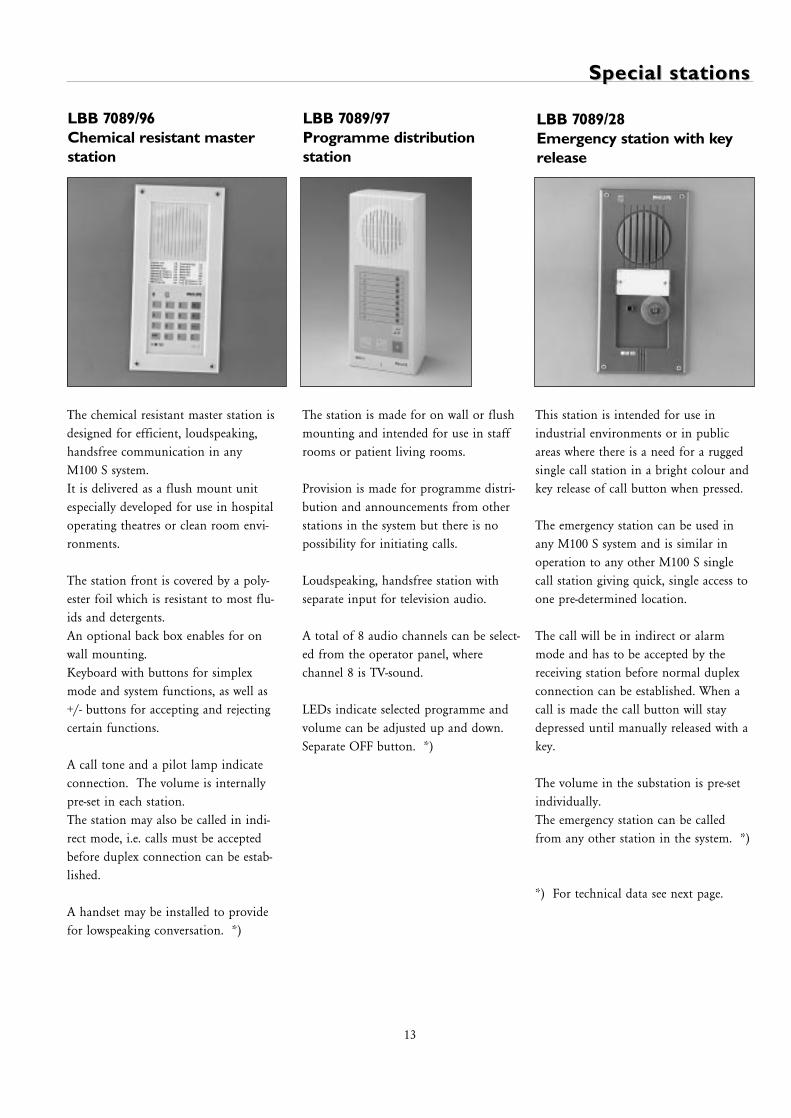
LBB 7089/96 Chemical resistant masterstation
The chemical resistant master station isdesigned for efficient, loudspeaking,handsfree communication in any M100 S system.It is delivered as a flush mount unitespecially developed for use in hospitaloperating theatres or clean room envi-ronments.
The station front is covered by a poly-ester foil which is resistant to most flu-ids and detergents. An optional back box enables for onwall mounting.Keyboard with buttons for simplexmode and system functions, as well as+/- buttons for accepting and rejectingcertain functions.
A call tone and a pilot lamp indicateconnection. The volume is internallypre-set in each station. The station may also be called in indi-rect mode, i.e. calls must be acceptedbefore duplex connection can be estab-lished.
A handset may be installed to providefor lowspeaking conversation. *)
The station is made for on wall or flushmounting and intended for use in staffrooms or patient living rooms.
Provision is made for programme distri-bution and announcements from otherstations in the system but there is nopossibility for initiating calls.
Loudspeaking, handsfree station withseparate input for television audio.
A total of 8 audio channels can be select-ed from the operator panel, wherechannel 8 is TV-sound.
LEDs indicate selected programme andvolume can be adjusted up and down.Separate OFF button. *)
LBB 7089/97 Programme distributionstation
This station is intended for use in industrial environments or in publicareas where there is a need for a ruggedsingle call station in a bright colour andkey release of call button when pressed.
The emergency station can be used inany M100 S system and is similar inoperation to any other M100 S singlecall station giving quick, single access toone pre-determined location.
The call will be in indirect or alarmmode and has to be accepted by thereceiving station before normal duplexconnection can be established. When acall is made the call button will staydepressed until manually released with akey.
The volume in the substation is pre-setindividually.The emergency station can be calledfrom any other station in the system. *)
*) For technical data see next page.
LBB 7089/28Emergency station with keyrelease

14
Data - special stationsData - special stations
LBB 7089/96 LBB 7089/97 LBB 7089/28
Dimensions (wxhxd): 130x265x60 mm 93x224x70 mm 130x265x75 mm5.12x10.43x2.36 in 3.7x8.8x2.8 in 5.12x10.43x3 in
Wall cut-out: 100x227x60 mm3.94x8.94x2.36 in
Weight, net: 450 g 675 g 1.4 kg0.99 lb 1.5 lb 3.08 lb
Housing: White ABS plastic
Keyboard: Polyester foil
Environmental conditions Category: T2 T2 T3
Ambient temperature range:: 0-45oCRelative humidity: 10-95%Protection: IP 65 IP 40 IP 54/64 when properly sealed
Supply voltage: Intercom line, nominal: 36 V d.c. 40/18 V d.c. (extension line)Intercom line, min./max.: 13 - 40 V
Current consumption :Intercom line, station OFF: 0.3 mA 38/0.3 mA (extension line)Intercom line, station ON: 38 mAPower line idle: 20 mAPower line at max. output: 150 mA
Output power: 90/300 mW 300 mW/1 W 90/300 mW
Cabling:Extension line 2-wire 2-wire

15
Station kits and coStation kits and couplerupler
LBB 7072/10 Master station kit
LBB 7072/32 Single/Dual call station kit
The kit is a complete master station butdelivered without cabinet, intended forself-mounting or as a spare part kit forM100 S master stations.
The kit contains the following parts:- loudspeaker including wires with
connector- complete keyboard with all master
station keys and mounting frame- electret microphone with wires and
connector- station PCB with flat cable keyboard
connector- 4-wire station cable with open ends
The kit is a complete single/dual call sta-tion but delivered without cabinet, intend-ed for self-mounting or as a spare part kitfor M100 S single/dual call stations.
The kit contains the following parts:- loudspeaker including wires with
connector- an �A� and a �B� key for calling pre-set
numbers- reset key - red LED lamp for indication of station
in use- electret microphone with wires and
connector - station PCB with single-in-line key-
board connectors
Dimensions (wxhxd) in mm/inch: LBB 7072/10 LBB 7072/32
Environmental conditions, category: T1 T1Approval: CE CESupply voltage : 36 V d.c. 36 V d.c.- At the station, idle <10 V d.c. <10 V d.c.- At the station, in operation 18 - 36 V d.c. 18 - 36 V d.c.Current consumption- At the station, idle <0.3 mA <0.3 mA- At the station, in operation 25 - 38 mA 25 - 38 mAOutput power (continuous/peak): 90/300 mW 90/300 mW

16
Station kits and coStation kits and couplerupler
LBB 7999/35 M100 S P.A. coupler
M100 S P.A. coupler for connection toany line in the system provides interface toa Public Address system. The P.A. couplermay be called from any station.When called, a relay contact for e.g. switch-ing on the P.A. amplifier is activated, andthe audio line is connected to the input ofthe amplifier (600 ohm/0dBm).
The various station kits enhance the opera-tion of any M100 S station by providingunique functions in several combinationswhere required.LBB 7073/65, LBB 7073/66 and LBB 7073/67 can be mounted in the coverof the station itself whereas the applicationkit LBB 7073/68 requires mounting inoptional back box.
External call/door opening and heavyduty handset kit do not require externalpower supply. All other functions requirea local or central external power supply.
Technical data LBB 7999/35 LBB 7073/65 LBB 7073/66
Dimensions (wxhxd) in mm/inch: 65x120x40/2.6x4.7x1.6 70x24x68/2.8x0.9x2.7 70x24x68/2.8x0.9x2.7Weight, net, in kg/lb: 0.100/0.2 0.055/0.1 0.055/0.1Environmental conditions, category: T2 T1 T1IP code: 42Approval: CE CE CESupply voltage : 36 V d.c. 36 V d.c.
At the station, idle <10 V d.c. 0 V d.c.At the station, in operation 18 - 36 V d.c. 15 V d.c.
Current consumption 24-36 V d.c./18-30 V a.c. 24-36 V d.c./18-30 V a.c.At the station, idle <0.3 mA 0 V 0 V At the station, in operation 27 mA 6-10 mA 6-10 mA
Output power (continuous/peak): 6 W in 8 ohms 6 W in 8 ohmsCabling:
Extension line 2-wire 2-wire 2-wirePower line 2-wire 2-wire
This kit includes
- 6 W peak power amplifier for use with external loudspeaker or improved internal loudspeaker performance
- Relay function with adjustable timer for activating an external call device or for remote door-opening function
- Opto coupler output for station-on signal to external equipment
6W Amplifier
Supply voltage:From ext. power, max. 40 V d.c./30 V a.c.From ext. power, min. 24 V d.c./18 V a.c.Current consumption:From unregulated power 80 mA average From regulated power 300 mA maxRelay ratings:Relay timing 0.8 - 35 sec. Maximum switchable voltage
50 V d.c./125 V a.c.Maximum switchable current 1 A.
LBB 7073/66Audio kit
This kit includes
- 6 W peak power amplifier for external or improved internal loudspeaker per-formance
- Interface circuitry for connection of heavy duty handset
LBB 7073/65 Audio/Relay kit

17
Station kits and coStation kits and couplerupler
LBB 7073/67Relay kit
LBB 7073/68Application kit
This kit includes:
- Relay function with adjustable timer for activating an external call device or for remote door-opening function
External call/door opening
Relay ratings:Relay timing 0.8 - 35 sec. Maximum switchable voltage
50 V d.c./125 V a.c.Maximum switchable current 1 A
Technical data: LBB 7073/67 LBB 7073/68
Dimensions (wxhxd) in mm/inch: 70x24x68/2.8x0.9x2.7 102x48x130/5.1x1.9x5.1 Weight, net, in kg/lb: 0.055/0.1 0.160/0.4
This kit includes:
- 16 W peak power amplifier for use with external loudspeaker
- Relay function with adjustable timer for activating an external call device or for remote door-opening function
- Interface circuitry for connection of heavy duty handset
- Opto coupler output for station-on signal to external equipment
- 24 V station-on lamp driver
16 W AmplifierSupply voltage:From ext. power, max. 42 V d.c./30 V d.c.From ext. power, min. 24 V d.c./18 V a.c.Current consumption:From unregulated power
200 mA average at 16WFrom regulated power 800 mA max.
Opto coupler interfaceMaximum OFF voltage: 30 V d.c.Maximum reverse voltage: 7 V d.c.Source/sink current, maximum: 50 mA

18
Station accessoriesStation accessories
HANDSET KITS
LBB 7073/80Desktop handset kit
For LBB 7089/10 Desktop master stations.
LBB 7073/82Handset with cradle kit
For use with master stations in noisyareas or when confidentiality is required.
LBB 7073/84Cradle bracket
For table-top use of compact stations.
FRAMES AND BACK BOXES
LBB 7071/71Heavy duty handset kit
For use with Industrial stations.
LBB 7073/70Flush mount frame
For flush mounting of compact stations with or without back box.Dimensions (wxhxd): 130x265x18 mm
5.12x10.43x0.71 inCut-out hole (wxhxd): 107x231x63 mm
4.21x9.09x2.48 in
LBB 7073/60On wall back box
For on wall mounting of heavy dutyand industrial stationsStation cord and termination included.Dimensions (wxhxd): 130x265x67 mm
5.12x10.43x2.64 in
For use with compact master stations.
LBB 7073/73Weather protection frame
Metal frame lacquered in grey for weather protection of industrial stations.Dimensions(wxhxd): 140x272x80mm
5.51x10.79x3.15 in
LBB 7073/61Flush mount back box, 60 mm
For flush mounting of compact andindustrial stations.Station cord and termination included.Compact stations need flush mountframe.Dimensions (wxhxd): 120x254x60 mm
4.72x10.00x2.36 inCut-out hole (wxhxd): 108x234x60 mm
4.25x9.21x2.36 in

19
Station accessoriesStation accessories
LBB 7073/62On wall back box, plasticversion
For on-wall mounting of compact stations.Station cord and termination included. Dimensions (wxhxd): 130x265x75 mm
5.12x10.43x2.95 in
LBB 7073/63Flush mount back box, 75 mm
For flush mounting of heavy duty indus-trial stations. Station cord and termina-tion included. Compact stations require flush mountframe.Dimensions (wxhxd): 120x254x75 mm
4.72x10.00x2.95 inCut-out hole (wxhxd): 108x234x75 mm
4.25x9.21x2.95 in
LBB 7073/74Outdoor station heating kit
A heating kit may be mounted for out-door stations located where temperatures
down to -25oC can be expected. Alsosuitable for drying-out condensed water.Dimensions (wxhxd): 91x96x20 mm
3.58x3.78x0.79 inWeight, net: 90 g
0.2 lbPower rating: 12 W at 24 V
maximum: 25 W at 36 VTemperature
elevation at 12 W: +10oC
STATION CORDS, WALLSOCKETS AND PLUGS
LBB 7069/08Wall socket, 6-pole, 10 packRequires soldering of the installationcable inside the socket.
LBB 7069/186-pole plug, male, 10 pack
LBB 7069/21Wall socket, snap-in, 4-pole, 10 packThis socket has screw connection for theinstallation cable.
LBB 7069/62Station cord, snap-in connector, 10 pack
LBB 7069/63Station cord, 6-pole connector, 10 pack
LBB 7069/64Station cord interconnector, 4-pole, 10 packThis interconnector is used to extend thestation cable by connecting two or morestation cords in series.
LBB 7095/01Power supply, 24 V/40 W-Euro connector
Will provide local power for up to 5 sta-tions with audio/relay kit, or 2 stations with application kit.Dimensions (wxhxd) in mm/inch:
100x63x47/3.9x2.5x1.9Weight in kg/lb: 0.250/0.6Input voltage: 198 - 264 V a.c.Output voltage: 24 V d.c.Load current: 1.5 AApproval: CE

20
Station and accessorStation and accessory combinationsy combinations
STANDARD STATIONSLBB 7089/10 Desktop master station < < - - § - - - - - - - - ¤ -LBB 7089/15 Compact master station - < < - § - § § < § < - - ¤ -LBB 7089/16 Compact master display station - < < - § - § § < § < - ¤ ¤ -LBB 7089/18 Compact master display w/back light - < < - § - § § < § < - ¤ ¤ -LBB 7089/31 Single call station - < < - § - § § < § < - - ¤ -LBB 7089/32 Dual call station - < < - § - § § < § < - - ¤ -
INDUSTRIAL STATIONSLBB 7089/20 Industrial master station - < - § § - < < - < - < - < §LBB 7089/30 Industrial master display w/back light - < - § § - < < - < - < ¤ < §LBB 7089/21 Industrial single call station - < - § § - < < - < - < - < §LBB 7089/22 Industrial dual call station - < - § § - < < - < - < - < §
HEAVY DUTY STATIONSLBB 7089/40 Heavy duty master station - - - < ¤ - - - - - - - ¤ - <LBB 7089/41 Heavy duty single call station - > - § § - < > - < - < - § §LBB 7089/42 Heavy duty dual call station - > - § § - < > - < - < - § §
SPECIAL STATIONSLBB 7089/50 Explosion-proof master station IIC - - - - - ¤ - - - - - - ¤ - -LBB 7089/52 Explosion-proof dual call station IIC - - - - - ¤ - - - - - - ¤ - -LBB 7089/96 Chemical resistant master station - > - - § - < < - < # - - ¤ -LBB 7072/10 Master station kit - < - § § - - - - - - - - < -LBB 7072/32 Single/Dual call station kit - < - § § - - - - - - - - < -LBB 7076/12 Programme distribution station - - - - § - § § # § < - - ¤ -
Accessories
StationsLB
B 7
073/
80 D
eskt
op h
ands
et k
itLB
B 7
073/
82 H
ands
et w
ith
crad
le k
itLB
B 7
073/
84 C
radl
e br
acke
tLB
B 7
071/
71 H
eavy
dut
y ha
ndse
t ki
t
LBC
349
0/10
Lou
dspe
aker
hor
n, 1
6 oh
mLB
B 7
071/
10 F
lam
e-pr
oof
loud
spea
ker
horn
,
8 W
/8 o
hm
LBB
707
3/60
On
wal
l ba
ck b
ox
LBB
707
3/61
Flu
sh m
ount
bac
k bo
x, 6
0 m
m
LBB
707
3/62
On
wal
l ba
ck b
ox, p
last
ic
LBB
707
3/63
Flu
sh m
ount
bac
k bo
x, 7
5 m
m
LBB
707
3/70
Flu
sh m
ount
fra
me
LBB
707
3/73
Wea
ther
pro
tect
ion
fram
e
Ext
erna
l po
wer
sup
ply
Stat
ion
cord
LBB
707
3/74
Out
door
sta
tion
hea
ting
kit
Loud-speakers
Handsets Mountingaccessories
PSU/Cords
< = Possible ¤ = Required- = Not possible § = Possible in combination with other accessories# = Included > = Not recommended
Heatingkit

21
Kit and accessorKit and accessory combinationsy combinations
LBB
708
9/97
Pro
gram
me
dist
ribu
tion
sta
tion
LBB
708
9/10
Des
ktop
mas
ter
stat
ion
LBB
708
9/15
Com
pact
mas
ter
stat
ion
LBB
708
9/16
Com
pact
mas
ter
disp
lay
stat
ion
LBB
708
9/18
Com
pact
mas
ter
disp
lay
stat
ion
wit
h
ba
ck l
ight
LBB
708
9/31
Sin
gle
call
sta
tion
LBB
708
9/32
Dua
l ca
ll s
tati
onLB
B 7
089/
20 I
ndus
tria
l m
aste
r st
atio
nLB
B 7
089/
30 I
ndus
tria
l m
aste
r di
slay
sta
tion
wit
h ba
ckli
ght
LBB
708
9/21
Ind
ustr
ial
sing
le c
all
stat
ion
LBB
708
9/22
Ind
ustr
ial
dual
cal
l st
atio
nLB
B 7
089/
40 H
eavy
dut
y m
aste
r st
atio
nLB
B 7
089/
41 H
eavy
dut
y si
ngle
cal
l st
atio
nLB
B 7
089/
42 H
eavy
dut
y du
al c
all
stat
ion
LBB
708
9/50
Exp
losi
on-p
roof
mas
ter
stat
ion
IIC
LBB
708
9/52
Exp
losi
on-p
roof
dua
l ca
ll s
tati
on I
ICLB
B 7
089/
96 C
hem
ical
res
ista
nt m
aste
r st
atio
nLB
B 7
072/
10 M
aste
r st
atio
n ki
tLB
B 7
072/
32 S
ingl
e/D
ual
call
sta
tion
kit
LBC
349
0/10
Lou
dspe
aker
hor
n, 1
6 oh
mLB
B 7
071/
10 F
lam
e-pr
oof
loud
spea
ker
horn
, 8W
8oh
mLB
B 7
073/
60 O
n w
all
back
box
LBB
707
3/61
Flu
sh m
ount
bac
k bo
x, 6
0 m
mLB
B 7
073/
62 O
n w
all
back
box
, pla
stic
LBB
707
3/63
Flu
sh m
ount
bac
k bo
x, 7
5 m
mLB
B 7
073/
70 F
lush
mou
nt f
ram
eE
xter
nal
pow
er s
uppl
y
KITSLBB 7073/65 Audio/Relay kit < < < < - < < < § < < - < < - - < < < < - < < < < - ¤ LBB 7073/66 Audio kit < < < < - < < < § < < - < < - - < < < < - < < < < - ¤ LBB 7073/67 Relay kit < < < < - < < < § < < - < < - - < < < - - < < < < - - LBB 7073/68 Application kit - - § § - § § § § § § # § § - - § < < < - < < - < - ¤LBB 7073/74 Outdoor station - - - - - - - § § § § < § § - - - - - - - < < - < - -
station heating kit
< = Possible- = Not possible# = Included¤ = Required§ = Possible in combination with other accessories
Accessories
Kits
Stations
Loud
spea
kers
Bac
k bo
xes
and
fram
es
Pow
er S
uppl
y

22
System bSystem build-up and descriptionuild-up and descriptionM100 Nurse Call System
The Philips M100 Nurse call and Hospitalcommunication system consists of a num-ber of communication terminals forpatients and staff, partly controlledthrough PAN buses connected to one ormore exchanges with or without an ODINdistribution network.
The heart of the system is the intercomexchange. This can be:
A stand-alone exchange ranging from 2 to 384 subscribers in a centralized system
orA network exchange ranging from 2 to768 subscribers in a decentralized system
The exchanges are expandable in modules.In a network several exchanges can be con-nected over ODIN for up to more than10.000 subscribers.
Every exchange has its own typenumberbut every module and system allows choices of:
- Number and type of line cards in steps of 8 subscriber lines
- Type of line termination
- Optional voice card for digitalized voice messages
Tieline or telephone couplers
All these are described separately in theM100 S-72 Exchange family systemdescription.
The following system components are connected to the exchanges:
- Intercom stations
- Bedside stations
- Nurse desks
- One or more PCs
- Entertainment programme sources
- DP6000 Paging system
A nurse call system consists of several independent PAN areas.
A PAN area is normally a patient roomwith integrated bath/toilet or a bath/toiletarea. Other configurations can be chosen.
Each PAN area must have at least one bed-side station, one PAN controller plug-incard and a number of PAN terminalsaccording to the individual needs.
The PAN area is arranged in groups. A group is normally a bedside stationand/or terminals associated with one hospital bed or toilet(s). Other definitionsmay be chosen.
Each PAN area includes up to 8 groups: one common group, 6 bed groups and one toilet group. The PAN controller offers up to 10 functions per group.
PAN controller plug-in board is a separate printed circuit board that contains the controller of the PAN system.
This plug-in board is mounted in one bedside station in a PAN area and includes a microprocessor-based PAN bus driver.
The controller transmits and receives PAN information on the 2-wire PAN bus to and from all terminals in that PAN area. The power to the terminals is connected tothe same PAN bus.
PAN signalling is given as a lamp signal code, a display pager message and/or display on a nurse desk.
The lamp information may be transferredon a separate 4-wire lamp bus connected tothe PAN controller to a common corri-dor lamp to indicate the highest prioritycall from a group of rooms.
The PAN controller plug-in board and thebedside station part are powered from alocal 24 V d.c. power supply.

23
System bSystem build-up and descriptionuild-up and description
All PAN data is transmitted to an inter-com exchange.
The exchange is configured by a mainte-nance PC to handle the data thereaftergiven as alphanumeric information on adisplay station (nurse desk) and/or inradio-paging receivers as a bleep patternand numeric terminal number (ward,room and bed).
One or more Nurse desks or PC terminalsare normally connected for use at centralpoints like head nurse, staff room, etc.
These stations will, in addition to operat-ing as normal intercom stations for com-munication, display all calls and call status.
PC programs such as System maintenanceprogram for Windows for setting andchanging system parameters, Nurse call
program for administration of patient-to-staff communication, nurse interface topaging or statistical program for logging,are available.
This means that one or more PCs are normally connected for maintenance andadministration purposes.
As part of the �comfort-for-the-patients�concept, up to 10 entertainment pro-grammes can be selected by the patientfrom the remote control connected to eachbed station.
The sources for these programmes are con-nected to the intercom exchange for distri-bution to the entire system.
A Philips DP 6000 Paging system will, ingeneral, be connected to the Nurse callsystem.
The paging system consists of a transmitterand several receivers, normally with anumeric display and audio indication sepa-rating different call types.
When a patient, assistance or alarm call isinitiated the display will show the ward,room and bed number and the tone willindicate the type of call.
The nurse can go to the nearest intercomstation, key the displayed digits as shownon the paging receiver and get in immedi-ate contact with the patient calling.
The paging system is connected to thenurse call system via a PC running thenurse call program.
Basic operational flow chart

24
Equipment and accessoriesEquipment and accessories
LBB 7077/10Bedside station
Two parallel remote controlconnectors
Two independant medical alarm connectors
Presence/reset button
Assistance button
Alarm button
Presence/Reset button
- Green button with presence symbol- Push when present at patient- Steady green light when operated- Reset the call when leaving the patient- Glowing position light
Assistance button
- Yellow button with assistance symbol- Push to call for assistance- Flashing yellow light when operated- Glowing position light
Alarm button
- Red button with alarm symbol- Push and hold for 3 seconds to call for
emergency assistance- Flashing red light when operated- Glowing position light
Dual medical alarm connection- 2 x 6-pin RJ45 modular connector for
external alarm- Activated by contact closure or opening
in external surveillance equipment- Glowing position lights, flashing when
operated- Safety:External alarm if plug removed,
push Reset within 3 seconds to avoid alarm call
- 2 seconds flashing light for OK confirmation when plug is connected
Dual remote control connection
- 2 x 8-pin RJ45 modular connector for pear button/remote PAN control units LBB 7077/30/31/32 or /33
- Glowing position light- Safety:Nurse call if plug removed, push
Reset within 3 seconds to avoid alarm call
- 2 seconds flashing light for OK confirmation when plug is connected
Loudspeaking intercom
- Loudspeaking handsfree duplex conver-sation
- Microphone in remote control- Can be called from nurse desk or other
intercom stations- Can not initiate calls
Note: If both remote control inputs areused, one should be an LBB 7077/30Patient remote call to avoid conflictbetween bed light, programme and TVselections.
LBB 7077/00PAN controller plug-in board
Each PAN area must have one PANcontroller and a number of PAN terminalsaccording to number of beds and func-tions. The PAN controller plug-in cardmust be mounted in one of the bedsideintercom stations (group 0-6).

25
Equipment and accessoriesEquipment and accessories
Nurse call* Generates a call request to the nursing
staff* Position light* Confirmation light when operated
Programme selection* Turns ON audio programmes* Steps through 10 audio programmes* Selected programme displayed as:
1, 2. ...0* TV sound displayed as: ¤* Programme OFF displayed as: -
Audio volume* Increase audio volume by + button* Decrease volume by - button* 8 steps, step 4 = normal
Microphone * LBB 7077/31/32 only
Bed lamp switch* Toggle bed light ON and OFF* Optional bistable impulse relay
LBB 7076/75 is needed
TV on/off* Toggles TV set ON and OFF* PAN TV interface - U40
LBB 7077/71 must be connected to the PAN bus
TV programme selection* Select TV channel up and down* PAN interface terminal LBB 7077/71
must be connected to the PAN bus
Headset connection * LBB 7077/31/32 only* 3.5 mm jack for headset* Loudspeaking intercom calls will inter-
rupt programme
LBB 7077/70Cord saver - RJ45
All remote controls have a male/femaleconnector in the cord approx. 15 cm fromthe remote control RJ-plug. These connec-tors act as a �fuse� to ensure that neitherthe bedside station nor the remote controlwill be damaged if the remote control isaccidently pulled.
A nurse call is initiated if the cord saver isreleased. The call can be avoided if thereset button is pushed within 3 seconds.Normal situation is restored when thecord saver is re-connected. The LED willblink for 2 seconds to confirm connection.
LBB 7077/36Cradle for remote control
Remote control functions

LBB 7077/41Presence & assistance terminal
26
Equipment and accessoriesEquipment and accessories
- Frame and housing not included- Fits in standard U40 housing for on
wall and flush mount
LBB 7077/35Pull-cord terminal
LBB 7077/31Patient remote audio
LBB 7077/32Patient remote audio & TV
LBB 7077/33Patient remote call & light
LBB 7077/71PAN TV Interface
- Infra-red remote control for TV on/off and channel selection. Operated by LBB 7077/32
- The TV interface terminal is delivered with frame and casing
- A TV audio trafo kit is included in the type no. Can also be delivered separately
- Generates a nurse call to the staff- Red flashing light when in operation - Glowing position light- 190 mm nylon red pull-cord- Frame and housing included for on
wall mounting- IP 54 protection
LBB 7077/40Presence, assistance & alarmterminal
- Frame and housing not included- Fits in standard U40 housing for on-
wall and flush mount
LBB 7077/30Patient remote call
PATIENT REMOTECONTROLS
TERMINALS

27
Equipment and accessoriesEquipment and accessories
LBB 7077/42Presence terminal
- Frame and housing not included- Fits in standard U40 housing for on
wall and flush mountPresence/Reset button- Green button with presence symbol- Push when present at patient- Steady green light when operated- Reset call when leaving the patient- Glowing position light
LBB 7077/43Presence & alarm terminal
- Frame and housing not included- Fits in standard U40 housing for on
wall and flush mountPresence/Reset button- Green button with presence symbol- Push when present at patient- Steady green light when operated- Reset call when leaving the patient- Glowing position lightAlarm button- Red button with alarm symbol- Push and hold for 3 seconds to call for
emergency assistance- Flashing red light when operated- Glowing position light
LBB 7077/44Call button terminal
- Generates a nurse call to the staff- Red button with nurse symbol- Red flashing light when operated- Glowing position light- Frame and housing not included- Fits in standard U40 housing for on
wall and flush mount
LBB 7077/45Patient remote terminal
- Frame and housing not included- Fits in standard U40 housing for on
wall and flush mount- Connector for Patient remote call
LBB 7077/30- Nurse call function only can be used in
remote controls LBB 7077/31/32/33- Flashing red light when operated - Glowing position light- Safety: Nurse call if plug removed,
push Reset for same bed within3 seconds to avoid safety call
- 2 seconds flashing light for OK confirmation when plug is connected
LBB 7077/50Dual external alarm terminal
- Frame and housing not included- Fits in standard U40 housing for on
wall and flush mountDual external alarm connection- 2 x 6-pin RJ45 modular connector for
external alarm- Activated by contact closure or opening
in external surveillance equipment- Glowing position lights, flashing when
operated- Safety: External alarm if plug removed,
push Reset button within 3 seconds to avoid safety call
- 2 seconds flashing light for OK confirmation when plug is connected
LBB 7077/51Alarm terminal - heavy duty
- Frame and housing not included- Fits in standard U40 housing for on
wall and flush mountAlarm button- Red button with alarm symbol- Push and hold for 3 seconds to call for
emergency assistance- Flashing red light when operated- Glowing position light

28
Equipment and accessoriesEquipment and accessories
- Steel plate box for on-wall mounting- Station cord and termination included- Size 120 x 254 x 75 mm
- Plain white plastic plate to blank out a terminal housing
- Snaps into terminal frames
LBB 7076/61/62/63Terminal housings - single,dual & triple
- Standard U40 format- For lush mounting of all PAN
terminals in standard U40 boxes- Casings for on-wall mounting included- White coloured plastic
LBB 7077/25PAN lamp terminal, single
- One lamp without glass in single white housing with frame and casing for on-wall mounting
- Can be programmed to follow any available light signal code in the system
- Coloured glass for selected light code function is optional
LBB 7077/26PAN lamp terminal, dual
- Two lamps without glass in dual white housing with frame and casing for on-wall mounting
- Both lamps can be individually pro-grammed to follow any available light signal code in the system
- Coloured glass for selected light code function is optional
LBB 7073/63Flush mount back box, 75 mm
LBB 7073/71Flush mount frame, white
- White plastic frame for flush mountingof bedside stations
- Fits LBB 7073/63/60 and /61
LBB 7076/60Terminal cover plate
LBB 7076/75Bi-stable control relay
- Bi-stable relay to toggle the bedhead light ON/OFF
- Connected to the BED LAMP terminal- Coil: 24 V d.c.
Switch: 250 V d.c./10 A

29
Equipment and accessoriesEquipment and accessories
LBB 7077/21Dual lamp terminal, 4-wirewith buzzer
- Two lamps without glass + buzzer in white triple housing with frame and casing for on-wall mounting
- Piezo electric buzzer for audio alert sig-nal in combination with lamp signal.
- Rapid or slow sound sequences accord-ing to call priority
- Built-in volume control- DIN STANDARD:
. Lamp marked �A� can be pro-grammed to either White or Red
. Lamp marked �B� is factory-set to Green
- DUTCH STANDARD:. Lamp marked �A� can be pro-
grammed to Yellow. Lamp marked �B� is factory-set to
White
NB: Can NOT be programmed to �Dutch hospital with reset only�
LBB 7077/22Triple lamp terminal, 4-wire
- Three lamps without glass in white triple housing with frame and casing for on-wall mounting
- DIN STANDARD:. Lamps are factory-set to White, Red
and Green- Indicates all call types
NB: Three lamps are not relevant in DUTCH standard
LBB 7076/26: REDLBB 7076/27: GREENLBB 7076/28: WHITELBB 7076/29: YELLOWLBB 7076/37: BLUE
LBB 7077/20Dual lamp terminal, 4-wire
- Two lamps without glass in white dual housing with frame and casing for on-wall mounting
- DIN STANDARD:. Lamp marked �A� can be pro-
grammed to either White or Red. Lamp marked �B� can be pro-
grammed to either Red or Green- DUTCH STANDARD:
. Lamp marked �A� can be pro-grammed to Yellow
. Lamp marked �B� can be pro-grammed to White Lamp terminal glass

30
TTechnical dataechnical data
LBB 7089/97 LBB 7077/10 Terminals Lamp terminalsProgramme Bedside stationdistributionstation
Dimensions (wxhxd) in mm/inch: 224x93x70/ 224x93x70/ 73x73x20/8.8x3.7x2.8 8.8x3.7x2.8 2.9x2.9x0.8
Including on-wall frame 83x83x28/3.3x3.3x1.1
LBB 7077/25: 83x83x48/3.3x3.3x1.9
LBB 7077/20/26: 155x83x48/6.1x3.3x1.9
LBB 7077/21: 225x83x48/8.9x3.3x1.9
LBB 7077/22: 225x83x48/8.9x3.3x1.9
Flush mounted 83x83x9/3.3x3.3x0.04Weight, net in kg/lb: 0.675/1.5 0.675/1.5 0.040/0.1
Including on-wall frame 0.070/0.2LBB 7077/25:LBB 7077/20/26: 0.125/0.3LBB 7077/21: 0.180/0.4LBB 7077/22: 0.190/0.42
Housing:As delivered: White ABS plastic White ABS plastic None On wallLBB 7077/35/71: On wall
housing LBB 7076/61Keyboard: Polyester foil Polyester foil Polyester foilEnvironmental conditions, category: T2 T2 T2 T2
Ambient temperature range: 0-45oC 0-45oC 0-45oC 0-45oCRelative humidity: 10-95 % 10-95 % 10-95 % 10-95 %Approval: CE CE CE CE
Supply voltage:Intercom line, nominal: 36 V d.c. 36 V d.c.
min./max.: 13-40 V 13-40 VPower supply, nominal: 24 V d.c. 24 V d.c.
min./max.: 18-30 V 18-30 VFrom PAN bus, nominal: 24 V d.c. 24 V d.c.
min./max.: 18-26 V 18-26 V4-wire lamp bus, signal on: 12 V
signal off: 0 V d.c.signal blink: 6 V d.c.
Current consumption:Intercom line, station OFF: 0.3 mA 0.3 mA
station ON: 38 mA 28 mAPower line, lamp OFF: 10 mA
lamp ON: 190 mAidle: 20 mA 20 mAat max. output: 150 mA 110 mA
PAN bus, inactive terminal: 10 mA 10 mAsingle function, max.: 20 mA 20 mAdual function, max.: 30 mA 30 mA
Lamp bus 0 mA
31
TTechnical dataechnical data
LBB 7089/97 LBB 7077/10 Terminals Lamp terminalsProgramme Bedsidedistribution stationstation
Output power: 300 mW/1 WLoudspeaker Rloop=450 ohm: 25 mW
Rloop=0 ohm: 300 mW Headset 7 mW
Headset:Impedance 2x32 ohmPlug Stereo jack: 3.5 mm
Cabling:Extension line 2-wire 2-wireMax. loop resistance 450 ohmPower line 2-wire 2-wireFrom PAN bus 2-wire 2-wire 4-wireMax. loop resistance, at 0.2 A: 20 ohm
< 0.45 A: 20 ohm 20 ohmat 0.6 A: 16 ohm 16 ohm 8 ohmat 1.0 A: 8 ohm 8 ohm 4 ohmat 1.5 A: 2.7 ohmat 2.0 A: 2 ohm
IP code: 40 41 40 40LBB 7077/35 54

32
IntroduIntroductionctionM100 S-16/32 Intercom System
The M100 S-16 Intercom system isdesigned to provide cost-effective, hands-free internal communication in any organization with the need for up to 32extensions.
A basic system for up to 16 stations isavailable in a start pack with or withoutdisplay station comprising of the M100 S-16 Exchange equipped for fourlines, three M100 S Master stations and allequipment for installation. Just add twowires from each station location to the ter-mination board in the exchange.
This basic system is easily extended up to16 lines. Simply plug in more line cardsin the exchange, each providing
two new lines, and select more stations forindividual requirements from probably themost comprehensive and modular inter-com product range available. The simple two-wire star configuration caneasily be extended to cover new locations.
To extend above 16 lines, plug a secondM100 S-16 Exchange to the original one,and add line cards up to 32 lines.
Should the need for more than 32 exten-sions arise or special functions that are notavailable in the M100 S-16 be required, theexchange may, at any time, be unpluggedand replaced with a larger exchange in theS-72 range in just a few minutes.

33
The M100 S-16 Exchange provides as standardall the practical problem-solving solutionsdescribed below.
Two-way handsfree conversationKeying an extension number provides instantloudspeaking communication between two par-ties.
Two-way private conversationAs an option the M100 station may beequipped with a handset to allow privacy or forease of conversation in environments withextreme noise.
Indirect callThe caller may, for privacy reasons, place anindirect call which has to be accepted by thecalled party.
Simplex conversationConversation may be manually controlled fromany master station by push-to-talk, release-to-lis-ten operation of the SIMP button.
Microphone blockingThe microphone can be blocked during conver-sation by pressing the SIMP button. This placesthe station in listen mode.
Automatic line releaseIncomplete dialling or calls to non-existentnumbers or shorted lines will release number-unobtainable signal and be reset.
Automatic queuingIf both channels should be busy a call will enterqueuing for up to 30 seconds and be automati-cally set up as soon as a speech channelbecomes free.
Wait-on-busyCalls to a busy station will be automaticallyconnected if the busy station becomes free with-in 30 seconds.
Break-inEnables a caller with an urgent message to inter-rupt an existing conversation. The other party will be placed in hold hearing ahold signal during the break-in conversation.
Call-meIf the called subscriber is not present the callermay leave a call-me information indicated by aflashing lamp. When the subscriber returns,the call is established by keying a code.
Automatic transfer (patch option)Subscribers may instruct the system to transferall incoming calls to any other station.
Follow meSubscribers may instruct the system to transferall incoming calls to the extension where theyare presently located.
Consult callDuring a normal two-way conversation a thirdparty may be called for consultation, leaving theother party in hold.
Call transferA call may be transferred to a third party.
Add-in conferenceA conference may be set up between any num-ber of subscribers.The conference will be in simplex mode.Individual subscribers may withdraw from theconference.
Secretarial filter and transferA predefined executive station may route allincoming calls to a secretary for filtering.One executive/secretary pair is available inM100 S-16, two in M100 S-32.
Group callEnables a one-way announcement to be givento predetermined groups of stations. Three groups are predefined.
All call Enables a one-way announcement to be givento all extensions, i.e. for voice paging.
Emergency callEnables a one-way emergency announcement toall extensions with priority over all other calls. A special emergency call tone is provided fordistinction from normal calls.
Public Address accessThe M100 system may be linked to one ormore P.A. system(s) for making P.A. announce-ments from any M100 station.The link is provided by a P.A. coupler whichcan be connected to any of the S-16/32 lines.
Programme distributionEach subscriber with a master station may listento a distributed programme. Programme distri-bution will not interfere with normal use of theintercom system. The programme will be muted
during calls. The programme source is connect-ed directly to the programme input socket ofthe M100 S-16.
Priority stationThe system can be factory-configured to includea special line for one priority station. Callsfrom this station will overrule any other call inthe system.
Display functionDisplay stations may be used for call identific-ation purposes. Calls can be identified eitherby language, independent symbols or byalphanumeric display text depending on theexchange program. Note that text must be pro-grammed by YOUR LOCAL PHILIPS DEALER.
Gate/door controlThe M100 system provides secure control ofentrance gates or doors.Door stations provide single button calls to oneor two predetermined locations, whereupon thedoor may be opened by pressing a button during the conversation. Calls from the doorstations may be automatically transferred to anymaster station, e.g. for night position.
Two lines are predefined for door operation inS-16 and four in S-32. Any M100 S single ordual call station may be used as a door station. For defining more than two lines for dooroperation, special substation programs are avail-able. By using M100 display stations call iden-tification can be obtained thereby identifyingwhich door or gate is calling before answering.
Function flexibilityThe extensive M100 product rangecontains functions and accessoriesfor a large number of problem- solving solutions.For specific requirements YOURLOCAL PHILIPS DEALER has a PC program for changing certain parameters in the exchange.Accordingly, some of the functionscan be adapted to special needs be-fore delivery. This application is de-scribed in the software section ofthis catalogue.
Function descriptionFunction description

34
ExExchangechange
The S-16 Basic exchange is housed in acabinet for wall mounting. Two connec-tors are provided for connecting a pro-gram source and for connection of a dataline when two S-16 exchanges are intercon-nected.
The cabinet contains a mother board withthe common exchange control circuitry, a termination board with screw terminalsfor connection of the line cabling, socketsfor up to 8 line cards and an optionalpower distribution board if central power-ing is desired.
On the mother board there are switchesfor system functions: single or double digitselection, module number if two S-16s areinetrconnected, executive/secretary combi-nation and door function.
Capacities:Subscribers/lines:.................................2-16Line cards:...............................................1-8Speech channels................................... 2Automatic queuing for free line (30 sec.).................................................... AllProgramme distribution channels.........1Group call (predefined numbers)..........3All call.........................................................1Emergency call (from two stations only)............................lCall me....................................................AllAutomatic transfer................................AllFollow me................................................AllAdd-in conference.................................AllExecutive/secretary pairs.........................1
Technical data: LBB 7111/00
Dimensions (wxhxd) in mm/inch:Exchange 234x396x96/9.2x16x3.8Power Supply 120x155x42/4.7x6.1x1.7
Weight in kg/lb:Exchange (net) 2.1/4.6Power Supply (net) 0.6/1.3Starter pack (gross) 5.0/11
Temperature range: 0 to +50oCRelative humidity: 15 to 90%Category: T1Protection provided by enclosure: IP 20Approval: CEPower consumption:
S-16 Basic exchange 230 V a.c., 45 VA max.Power supply LBB 7102/18 36 V d.c., 1.7 A - EMC
Mains voltage: 190 - 260 V a.c.Output voltage 36 V d.c.Max. load 1.7 A
LBB 7111/00S-16 Basic exchange

35
StarStart packst packs
LBB 7111/16S-16 Start pack with 3 stations In order to facilitate the first step towardsinstalling an intercom system a completestart pack has been designed whichincludes all you need in order to install acomplete system with three compact mas-ter stations. If more stations are desiredthese can be added by choosing from theextensive range of M100 Intercom stationsavailable.
LBB 7111/17S-16 Start pack with 8 stations
Identical to LBB 7111/16 but containing 8compact master stations and a correspond-ing number of line cards, station cordsand wall sockets, the latter based on the 6-pole Hirschmann concept.
LBB 7111/18S-16 Start pack with 3 stations, snap-in
Identical to the LBB 7111/16 but stationcords have snap-in connectors.
LBB 7111/19S-16 Start pack display with 3 stations, snap-in
Identical to LBB 7111/16 but the exchangeis equipped with display driver. Onedisplay station is included.
Contents of LBB 7111/16 S-16 Start pack with 3 stations:
1 x LBB 7111/00 S-16 Basic exchange2 x LBB 7111/20 S-16 Line card for 2 stations1 x LBB 7102/18 S-16 Power supply, 36 V/1.7 A - EMC3 x LBB 7089/15 Compact master station3 x LBB 7069/63 Station cord, 6-pole connector, 10 pack3 x LBB 7069/08 Wall socket, 6-pole, 10 pack
Add two wire installation cabling, more line cards, wall sockets, stations and accessories as required.
Contents of LBB 7111/19 S-16 Start pack Display with 3 stations, snap-in:
1 x LBB 7111/00 S-16 Basic exchange with built-in S-16 Display driver kit LBB 7111/51
2 x LBB 7111/20 * S-16 Line card for 2 stations1 x LBB 7102/18 S-16 Power supply, 36V/1.7 A - EMC2 x LBB 7089/15 Compact master station1 x LBB 7089/16 Compact master display station3 x LBB 7069/63 Station cord, 6-pole connector, 10 pack
* The display station requires two lines.

36
ExExchange accessorieschange accessories
For central powering of station kits.
LBB 7111/50Interconnection kit, two S-16 exchanges
Cables for interconnecting2 x M100 S-16 exchanges.
LBB 7111/51S-16 Display driver kit
Necessary exchange material to allow con-nection of display stations. In a double S-16 system a kit must be installed in bothcabinets if display stations are to be connected in both.
The special display program is delivered asa PROM chip which has to be pluggedinto the exchange replacing the standardprogram.
The display program caters for two displaystations, two master stations and 10 sub-stations.All other functions remain unchanged.
Note that display stations need two linepoints, i.e. four wires from the exchange:- one pair for station signal and power- one pair for display signal and power
Contents of S-16 Display driver kit, LBB 7111/51:
1 x Display driver PCB
1 x LBB 7201/12 S-16 10 substations/2 master�s display program
Mounting material
1 x Interconnection flat cable with plugs
The M100 S-16 basic exchange can beequipped in different ways in order to fur-ther extend system flexibility.
LBB 7111/20S-16 Line card for 2 stations
For the connection of stations or P.A. cou-plers.
LBB 7111/22S-16 Line card for 1 station/ 1 loudspeaker For the connection of one station and onehigh power loudspeaker horn.
LBB 7102/18S-16 Power supply, 36 V/1.7 A- EMC
For system powering, 36 V/1.7 A.
LBB 7111/32S-16 Power distribution board

37
SofSofttwareware
The standard M100 S-16 has a comprehen-sive function range. In order to make thesystem more adaptable to special require-ments alternative programs can be ordered.NB: These programs are delivered asPROM chips which have to be pluggedinto the exchange, replacing the standardprogram.
LBB 7201/10S-16 13 substations/2 masters program The basic M100 S-16 exchange caters forthe connection of two substations. LBB 7201/10 program can be ordered toextend the number of substations to13.All other functions remain as standard.
LBB 7201/11S-16 8 substations/2 mastersprogramIdentical to LBB 7201/10 but to extendthe number of substations to 8.All other functions remain as standard.
LBB 7201/30S-16 PC patch program
For tailor-making the M100 S-16 systemfunctions to specific demands YOURLOCAL PHILIPS DEALER has a PCpatch program at his disposal. With this program HE/SHE can adaptsome of the parameters in the exchange tocomply to special needs.With this S-16 PC patch program the fol-lowing parameters can be changed:
- Emergency call table- All call table- Group call menu- Emergency call start- Substation routing- Executive/secretary- Priority station- Display station- Display text editor- Include/remove functions
DISPLAY FUNCTIONS
When using one or more display stationsin the M100 S-16 system it is necessary toupdate the exchange.
Station idle:
# 12
Station calling:
Station being called:
Station being called whenbusy:
14
20
14 +
Adding text:
YOUR LOCAL PHILIPS DEALER canadd text to each number by using the LBB 7201/30 S-16 PC patch program.In this way called or calling station identi-fication can be made alphanumerically inyour own language in a user-friendly way.
The space available on the display for textis the first 12 characters in the upper linewhich is freely programmable per systemand the complete 16 characters in thelower line which is freely programable perline (station).
Letters from A-Z, a number of symbolsand the digits 0-9 are available for compos-ing the text.
In addition 6 special letters per exchangecan be selected from a menu in order toinclude specific letters in different languages.
NB: When parameters have been changedthe new function program will be deliv-ered as a PROM chip which has to beplugged into the exchange, replacing thestandard program.
LBB 7201/12S-16 10 substations/2 mastersdisplay programNB: Included in typeno.: LBB 7111/51
Program for controlling the displayedinformation when the display station isidle, calling, being called or being calledwhen busy. In order to avoid languageproblems the standard information dis-played is made using symbols and digits.
LBB 7201/13S-16 3 substations/11 mastersdisplay program
Identical to LBB 7201/12 but with anothersub to master station ratio.
38
IntroduIntroductionctionM100 S-72 Exchange Family Range
Exchange configurationsThe comprehensive range of exchangesavailable for Philips Intercom, Hospitaland Prison communication systems is sub-divided for easy selection, ordering andinstallation as follows:
SB-80 Basic function exchangeS-72 to S-384 Stand-alone exchangesSO-72 to SO-768 ODIN network exchanges
All exchanges can be extended to any larg-er stand-alone or networked exchange bysimple extension units and kits.
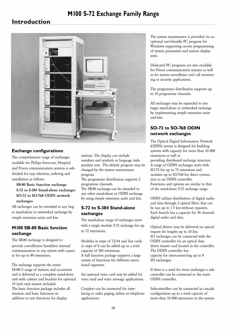
M100 SB-80 Basic functionexchangeThe SB-80 exchange is designed to
provide cost-effective handsfree internalcommunication in any system with capaci-ty for up to 80 extensions.
The exchange supports the entire M100 S range of stations and accessoriesand is delivered as a complete stand-aloneunit with cabinet and brackets for optional19 inch rack mount included.The basic function package includes allintrinsic and basic functions in addition to text functions for display
stations. The display can include numbers and symbols or language inde-pendent text. The default program may bechanged by the system maintenance program.The programme distribution supports 2programme channels.The SB-80 exchange can be extended toany other stand-alone or ODIN exchangeby using simple extension units and kits.
S-72 to S-384 Stand-aloneexchangesThe stand-alone range of exchanges startswith a single module S-72 exchange for upto 72 extensions.
Modules in steps of 72/64 and line cardsin steps of 8 can be added up to a totalcapacity of 384 extensions.A full function package supports a largevariety of functions for different opera-tional segments.
An optional voice card may be added forvoice mail and voice message applications.
Couplers can be connected for inter-facing to radio paging, tieline or telephoneapplications.
The system maintenance is provided via anoptional user-friendly PC program forWindows supporting on-site programmingof system parameters and station displaytexts.
Dedicated PC programs are also availablefor Prison communication systems as wellas for system surveillance and call monitor-ing in security applications.
The programme distribution supports upto 10 programme channels.
All exchanges may be expanded to anylarger stand-alone or networked exchangeby implementing simple extension unitsand kits.
SO-72 to SO-768 ODIN network exchanges
The Optical Digital Information Network(ODIN) system is designed for buildingsystems with capacity for more than 10 000extensions as well as providing distributed exchange structure.A range of ODIN exchanges starts withSO-72 for up to 72 extensions and escalates up to SO-768 for direct connec-tion to an ODIN controller.Functions and options are similar to thatof the stand-alone S-72 exchange range.
ODIN utilizes distribution of digital audioand data through 2 optical fibres that canbe run up to 1.5 km without repeaters. Each branch has a capacity for 30 channelsdigital audio and data.
Optical drivers may be delivered on specialrequest for lengths up to 10 km. SO exchanges can be connected with theODIN controller via an optical data driver master card located in the controller.The ODIN controller has capacity for interconnecting up to 8 SO exchanges.
If there is a need for more exchanges a sub-controller can be connected to the mainODIN controller.
Subcontrollers can be connected in cascadeconfiguration up to a total capacity ofmore than 10 000 extensions in the system.

39
Function descriptionFunction description
Intrinsic functions (SB, S and SO)
Two-way handsfree conversationKeying an extension number providesinstant loudspeaking communicationbetween two parties.
Two-way private conversationMost M100 S stations may be equippedwith a handset to allow privacy or forease of conversation in environmentswith high noise level.
Simplex conversationConversation may be manually con-trolled from any calling master stationby «push-to-talk», «release-to-listen» oper-ation of the SIMP button.
Microphone blockingThe microphone can be blocked duringconversation by touching the «SIMP»button. This places the station in listen-ing mode.
Wait-on-busyCalls to a busy station will be automati-cally connected if the busy stationbecomes free within 30 seconds.
Basic functions (SB, S and SO)Call me (lamp indication)If the called subscriber is absent, thecaller may leave a call-me informationin the form of a flashing pilot lamp.
When the subscriber returns, the call isestablished by keying a code.
Automatic recallWhen calling a busy station the callermay request automatic recall as soon asboth extensions become free.
Break inEnables a caller with an urgent messageto interrupt an existing conversation.
Three-way conferenceA three-way duplex conference may beestablished between any three exten-sions.
Consult callDuring normal two-way conversation athird party may be called for consulta-tion, leaving the other party in hold.
Follow meSubscribers may instruct the system totransfer all incoming calls to the exten-sion where they are presently located.
Group call with replyEnables a one-way announcement to begiven to predetermined groups of sta-tions. (Standard 8 groups, optional 80).
Ongoing conversations will be re-estab-lished automatically when the group callis finished.
Within a defined period of time the ini-tiator may be called from any extensionby keying a code.
All call with replyEnables a one-way announcement to begiven to all extensions, i.e. for voice pag-ing with priority over group call.Otherwise the same as group call.
Emergency call Enables a one-way emergencyannouncement to be given to allextensions with priority over all othercalls.
A special emergency call tone differenti-ates from normal call tone.Ongoing conversation will not be re-established.
Loudspeaker connectionHorn loudspeakers may be called likeany other extension for "press-to-talk","release-to-listen" operation when specialline cards are installed.
Programme distributionEach subscriber with a master stationhas the choice of accessing programmechannels.
Single, dual or special stations may alsobe set up to receive the programmechannels.
The number of programmes varies from1 to 10 depending on system configura-tion.
Substation with door openingAny extension may be programmed toaccept single button calls to maximum 9predetermined extensions in indirect ordirect mode with automatic time-out.
Direct callEach subscriber line may programme upto 9 different one digit calls, direct orindirect mode.
Display functionsAll extension lines can be enabled forconnection of LCD display stations forcall identification.
The calls will, in default mode, be ident-ified by language-independent symbols.
Customer-defined alphanumeric displaytext may be programmed via the systemmaintenance PC.
Extended functions(S and SO)
Call transferA call may be transferred to a third party.
Executive/secretaryA predefined executive station may routeall incoming calls to a secretary for filter-ing.
Executive/secretary, alwaysEnables the system operator to lock secre-tary filtering for a predefined exec./secr.pair.
Transfer alwaysEnables the system operator to route andlock incoming calls to another extension.
Transfer-on-busyEnables the system operator to route andlock incoming calls to another extensionwhen the called station is busy.

40
Function descriptionFunction description
Speech(optional by LBB 7103/48)
Voice mail A subscriber may leave a spoken messageto any other subscriber. The electronical-ly stored message will be heard by thereceiving party at any time.
Personal messageA subscriber may leave a spoken messageon own station. The electronically storedmessage will be heard by all calling par-ties.
Absence messageThe system may be instructed to pass on absence messages in verbal formfor absentee subscribers, notifying thecaller that the subscriber is absent, wherehe is and when he will be back. An absence message is selectable from apre-recorded menu.
Call-me messageIf the called party is not present a mes-sage may be left notifying the subscriberto call back. Call-back messages are indi-cated by flashing pilot lamp on the sta-tion.
Time callTime of the day will be given when key-ing appropriate code from the stationkeyboard.
Number identificationAny subscriber may check own extensionnumber by keying appropriate codefrom the station keyboard thereuponreceiving a verbal messsage.
Nurse call segment functionsNurse deskAny station may be programmed tofunction as a nurse desk in a nurse callsystem. When using a display station the systemmay be set-up to display the callingward, room and bed number.
Bedside stationsAny station may be setup as bedside stations and room stations in a nursecall system.
Security segment functionsGuard deskDisplay station setup as guard desk withthe possibility of receiving call requestsfrom door/alarm stations in a queue.
The operator can freely select to answerthe desired calling station by scrollingthe LCD display.
Door/alarm stationExtension line configured to supportsingle/dual call type station making callrequests to a guard desk.
Appropriate text will be generated oncorresponding guard desk.
Music on hold for door/alarm stationA door/alarm station will automaticallybe switched to a programme distributionchannel after initiation of a call request.
When no source is connected to the pro-gramme channel, only pilot lamp will belit. On response and reset of the callrequest the door/alarm station willrevert to idle mode.
System maintenanceSystem maintenance PC program forWindows 3.11/W95 Maintenance PCprogram provides on-line adjustment ofthe following parameters:
- Floating numbers (1-6 digits)- Display text corresponding to each
subscriber line- Allocation of functions per sub-
scriber line- Programming of substations- Coupler programming- Storage and printing of all tables- General system parameters:
. Timer settings for various functions
. Application specific programming
. Nurse call and security system setup.
Coupler interfacesTieline couplerOpto or serial interface for inter-connecting M100 S to M100 S systemsand M100 S previously delivered M100 P systems via public telephonelines.
Telephone couplerOpto or serial interface for connectionto internal or public telephone networkdial-in or dial-out to/from intercom.
Paging interfaceOpto interface for connection ofDP6000 or similar paging system for on-site display paging.
PC call information protocolSerial communication with PC for useof standard or customized monitor pro-grams. The programs may be used actively insecurity applications or as logging forrecords.
Group huntSubscribers may be programmed to bea member of a group hunt table.
Calls to subscribers programmed inthe group hunt table need acceptanceof the receiving party.
Calls not answered within a presettime will be forwarded to the next sub-scriber.
Please note that if functions outsideshaded area are required in SB-80, theexchange must be upgraded.
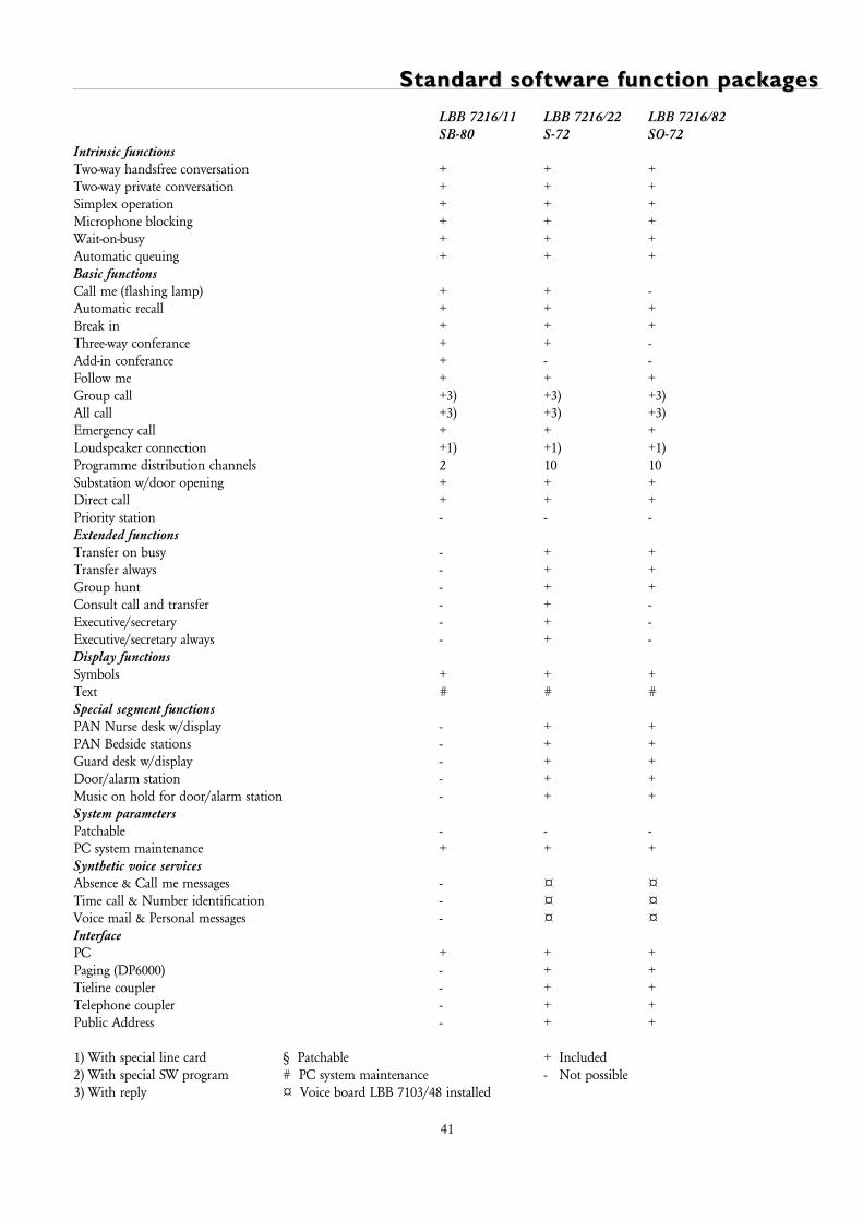
41
Standard sofStandard softtware function packagesware function packages
LBB 7216/11 LBB 7216/22 LBB 7216/82SB-80 S-72 SO-72
Intrinsic functionsTwo-way handsfree conversation + + +Two-way private conversation + + +Simplex operation + + +Microphone blocking + + +Wait-on-busy + + +Automatic queuing + + +Basic functionsCall me (flashing lamp) + + -Automatic recall + + +Break in + + +Three-way conferance + + -Add-in conferance + - -Follow me + + +Group call +3) +3) +3)All call +3) +3) +3)Emergency call + + +Loudspeaker connection +1) +1) +1)Programme distribution channels 2 10 10Substation w/door opening + + +Direct call + + +Priority station - - -Extended functionsTransfer on busy - + +Transfer always - + +Group hunt - + +Consult call and transfer - + -Executive/secretary - + -Executive/secretary always - + -Display functionsSymbols + + +Text # # #Special segment functionsPAN Nurse desk w/display - + +PAN Bedside stations - + +Guard desk w/display - + +Door/alarm station - + +Music on hold for door/alarm station - + +System parametersPatchable - - -PC system maintenance + + +Synthetic voice servicesAbsence & Call me messages - ¤ ¤Time call & Number identification - ¤ ¤Voice mail & Personal messages - ¤ ¤InterfacePC + + +Paging (DP6000) - + +Tieline coupler - + +Telephone coupler - + +Public Address - + +
1) With special line card § Patchable + Included2) With special SW program # PC system maintenance - Not possible3) With reply ¤ Voice board LBB 7103/48 installed

42
HoHow to bw to build a complete exuild a complete exchangechange
In order to build a complete Intercom,Hospital or Prison communication system the following steps must be consid-ered depending on the application:
1. Select exchange typeSelect any exchange by typenumber accord-ing to requirements for functions, numberof stations and network:
l SB-80 Basic function exchange for standard applications (page 43)
l S-72 to S-384 Stand-alone exchange(page 44-45)
l SO-72 to SO-768 ODIN network exchange (page 46-49)
2. Select Line cards (page 53)Select type and number of line cards:
l Line card, 8 stations
l Line card, 6 stations 2 loudspeaker points
l Line cards, 8 loudspeaker points
l Line card 6 stations, 2 couplers
l Open line check
3. Select line termination type (page 53)All incoming lines from connected station and terminals have to be terminated at the exchange.
l Line termination unit for up to 80 intercom extensions
l Line termination panel mounted at the rear of the exchange withline termination cables, each cable for connecting 16 2-wire extensions
4. Voice board (page 53)Select voice options:
l Voice card for pre-recorded messages and optional voice mail (requires RAM chip OC type)
l Requires one ACIA card in all ODIN exchanges
5. Connection of PCs (page 54)Select PC interface for the PC:
l VDU termination opto interface
l PC opto interface card for plastic fibre (max. 30 m)
l PC opto interface card for glass fibre(max. 1.5 km)
l Opto cable, plastic fibre (max. 30 m)
6. PC programs (page 59-60)Select type of PC programs.
l PC system maintenance program for Windows
l Basic call monitor program (not for SB-80)
7. Couplers (page 55)For interfacing to selective radio, paging,tieline or telephones.
8. ODIN network (page 56-57)SO exchanges used in an ODIN-networkrequire an ODIN controller.
Expanding installed exchanges (page 51-52)Select upgrade/expansion unit or kit:
l S-72 Sub-exchange
l S-64 Sub-exchange
l SB-80/S-72 Function upgrade kit
l SB-80/SO-72 Function upgrade kit
l S/SO Function upgrade kit
l 216/256 Expansion kit
l SO-320/SO-384 Expansion kit
For detailed information see relevantchapter in this system description.

43
M1M100 SB-80 Basic function ex00 SB-80 Basic function exchangechange
Technical data LBB 7112/00
Supply voltage from mains, strapable: 90-190/180-264 V a.c.Power consumption, from mains,typical/max.: 160/230 VADimensions in mm/inch:
Width 442/17.4Depth 310/12.20 ex. handsets and terminalsHeight 266/10.47
Net weight (kg/lb) approx.: 8/18Cabinet construction: Aluminium 19" boxed sub frame Mounting:
Table top Rubber feet19 inch rack mount Optional mounting brackets included
Speech channels: 6 internal Extensions and line terminations: 80 extensions, 4-wireProgramme distribution channels: 2Floating number capacity: Initially fixed to numbers 10-89Automatic recall capacity: 16Call-me capacity: 80
LBB 7112/00SB-80 Exchange Included in LBB 7112/00:
l LBB 7102/93 S-64 Power Supply supporting all required internal voltages and line voltage for 80 extensions. 36 V/2 A is available for power distribution to kits and display stations.
l LBB 7110/13 FC card supports the included functions, the display driver and 2 channel programme distribution or 1 channel distri- bution and 1 channel conference
l LBB 7105/95 Line termination unit terminates 80 2-wire extension linesas well as 80 2-wire power distribution lines.
SB-80 is a complete, basic functions stand-alone exchange. (Functions as describedin shaded areas on page 39).SB-80 can be upgraded to any S-72 or SO-72 exchange by expansion units orupgrade kits.
Special function for SB-80
Add-in conference with up to 32 participants:(Occupies programme distribution channel 2).
A simplex conference may be establishedfrom one controlling party, including upto 32 participants.
Each participant�s voice is heard by press-ing the �SIMP� button.
When used in conjunction with displaystations the name of the speaker will beshown on all display panels.
Pre-defined conference groups:Up to 5 different groups for conferencecan be pre-defined in the system mainte-nance program.
LBB 7109/26SB-80 Programming kit
Consisting of:
LBB 7109/21 VDU terminal opto interface
LBB 7215/22 PC System mainte-nance program for Windows
LBB 7103/61 Opto cable, 4 metres

44
M1M100 Stand-alone ex00 Stand-alone exchangeschanges
Technical data 7112/01, S-72 7112/02, S-144 7112/03, S-216
Supply voltage, strappable (V a.c.): 90-190/180-264 90-190/180-264 90-190/180-264Power consumption from mains,typical/max. (VA): 165/210 325/410 485/610Dimensions in mm/in.:
Width 442/17.40 442/17.40 442/17.40Depth 310/12.20 a) 310/12.20 a) 310/12.20 a)Height 266/10.47 (6U) 532/20.94 (12U) 798/31.42 (18U)
Net weight (kg/lb) approx.: 10/23.76 20/44 30/66Cabinet construction: 19� Aluminium sub-frame 19�� Aluminium sub-frames 19�� Aluminium sub-framesMounting:
19 inch rack mount option option optionExchange capacities:
Internal speech channels 7 2 x 7 3 x 7 Audio channels between modules 8 8Extensions 72 144 216 Programme distr. channels, max. 10 10 10List number capacity up to 72 numbers 2 - 6 digits up to 144 numbers 2 - 6 digits up to 216 numbers 2 - 6 digits Automatic recall capacity 32 32 32Call-me capacity 50 50 50
Functional capacity:FC card standard standard standard6U computer card standard standard standardVoice card option option optionODIN node NA NA NA
LCD display driver capacity: 1 channel 2 channels 3 channelsPeripheral equipment: PC, tieline and paging PC, tieline and paging PC, tieline and pagingFunction package b): LBB 7216/22 LBB 7216/22 LBB 7216/22a) Excluding handles in the front and terminals in the rear.b) Special function packages can be delivered upon request.
LBB 7112/01S-72 Exchange
LBB 7112/02S-144 Exchange
LBB 7112/03S-216 Exchange
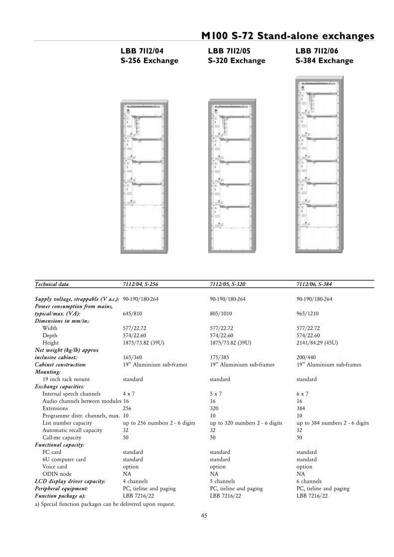
45
M1M100 S-700 S-72 Stand-alone ex2 Stand-alone exchangeschanges
Technical data 7112/04, S-256 7112/05, S-320 7112/06, S-384
Supply voltage, strappable (V a.c.): 90-190/180-264 90-190/180-264 90-190/180-264Power consumption from mains,typical/max. (VA): 645/810 805/1010 965/1210Dimensions in mm/in.:
Width 577/22.72 577/22.72 577/22.72Depth 574/22.60 574/22.60 574/22.60Height 1875/73.82 (39U) 1875/73.82 (39U) 2141/84.29 (45U)
Net weight (kg/lb) approxinclusive cabinet.: 165/360 175/385 200/440Cabinet construction: 19�� Aluminium sub-frames 19�� Aluminium sub-frames 19�� Aluminium sub-framesMounting:
19 inch rack mount standard standard standardExchange capacities:
Internal speech channels 4 x 7 5 x 7 6 x 7 Audio channels between modules 16 16 16Extensions 256 320 384 Programme distr. channels, max. 10 10 10List number capacity up to 256 numbers 2 - 6 digits up to 320 numbers 2 - 6 digits up to 384 numbers 2 - 6 digits Automatic recall capacity 32 32 32Call-me capacity 50 50 50
Functional capacity:FC card standard standard standard6U computer card standard standard standardVoice card option option optionODIN node NA NA NA
LCD display driver capacity: 4 channels 5 channels 6 channelsPeripheral equipment: PC, tieline and paging PC, tieline and paging PC, tieline and pagingFunction package a): LBB 7216/22 LBB 7216/22 LBB 7216/22a) Special function packages can be delivered upon request.
LBB 7112/04S-256 Exchange
LBB 7112/05S-320 Exchange
LBB 7112/06S-384 Exchange

46
M1M100 SO-700 SO-72 ODIN Net2 ODIN Netwwork exork exchangeschanges
LBB 7112/11SO-72 Exchange
LBB 7112/12SO-144 Exchange
LBB 7112/13SO-216 Exchange
Technical data 7112/11, SO-72 7112/12, SO-144 7112/13, SO-216
Supply voltage, strappable (V a.c.): 90-190/180-264 90-190/180-264 90-190/180-264Power consumption from mains,typical/max. (VA): 165/210 325/410 485/610Dimensions in mm/in.:
Width 442/17.40 442/17.40 442/17.40Depth 310/12.20 a) 310/12.20 a) 310/12.20 a)Height 400/15.75 (9U) 666/26.22 (15U) 932/36.69 (21U)
Net weight (kg/lb) approx: 16/35.2 26/57.2 36/79.2Cabinet construction: 19�� Aluminium sub-frames 19�� Aluminium sub-frames 19�� Aluminium sub-framesMounting:
19 inch rack mount option option optionExchange capacities:
Internal speech channels 7 2 x 7 3 x 7 Audio channels between modules 8 8Extensions 72 144 216 Programme distr. channels, max. 10 10 10List number capacity up to 72 numbers 2 - 6 digits up to 144 numbers 2 - 6 digits up to 216 numbers 2 - 6 digits Automatic recall capacity 32 32 32Call-me capacity 50 50 50
Functional capacity:FC card standard standard standard6U computer card standard standard standardVoice card option option optionODIN node standard standard standard
LCD display driver capacity: 1 channel 2 channels 3 channelsPeripheral equipment: PC, tieline and paging PC, tieline and paging PC, tieline and pagingFunction package b): LBB 7216/82 LBB 7216/82 LBB 7216/82a) Excluding handles in the front and terminals in the rear.b) Special function packages can be delivered upon request.
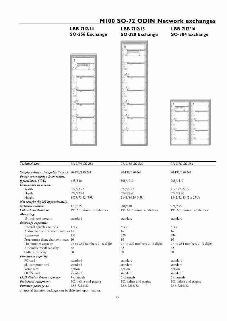
47
M1M100 SO-700 SO-72 ODIN Net2 ODIN Netwwork exork exchangeschangesLBB 7112/14SO-256 Exchange
LBB 7112/15SO-320 Exchange
LBB 7112/16SO-384 Exchange
Technical data 7112/14, SO-256 7112/15, SO-320 7112/16, SO-384
Supply voltage, strappable (V a.c.): 90-190/180-264 90-190/180-264 90-190/180-264Power consumption from mains,typical/max. (VA): 645/810 805/1010 965/1210Dimensions in mm/in.:
Width 577/22.72 577/22.72 2 x 577/22.72Depth 574/22.60 574/22.60 574/22.60Height 1875/73.82 (39U) 2141/84.29 (45U) 1342/52.83 (2 x 27U)
Net weight (kg/lb) approximately,inclusive cabinet: 170/375 200/440 270/595Cabinet construction: 19�� Aluminium sub-frames 19�� Aluminium sub-frames 19�� Aluminium sub-framesMounting:
19 inch rack mount standard standard standardExchange capacities:
Internal speech channels 4 x 7 5 x 7 6 x 7 Audio channels between modules 16 16 16Extensions 256 320 384 Programme distr. channels, max. 10 10 10List number capacity up to 256 numbers 2 - 6 digits up to 320 numbers 2 - 6 digits up to 384 numbers 2 - 6 digits Automatic recall capacity 32 32 32Call-me capacity 50 50 50
Functional capacity:FC card standard standard standard6U computer card standard standard standardVoice card option option optionODIN node standard standard standard
LCD display driver capacity: 4 channels 5 channels 6 channelsPeripheral equipment: PC, tieline and paging PC, tieline and paging PC, tieline and pagingFunction package a): LBB 7216/82 LBB 7216/82 LBB 7216/82a) Special function packages can be delivered upon request.

48
M1M100 SO-700 SO-72 ODIN Net2 ODIN Netwwork exork exchangeschangesLBB 7112/17SO-448 Exchange
LBB 7112/18SO-512 Exchange
LBB 7112/19SO-576 Exchange
Technical data 7112/17, SO-448 7112/18, SO-512 7112/19, SO-576
Supply voltage, strappable (V a.c.): 90-190/180-264 90-190/180-264 90-190/180-264Power consumption from mains,typical/max. (VA): 1125/1410 1285/1610 1445/1810Dimensions in mm/in.:
Width 2 x 577/22.72 2 x 577/22.72 2 x 577/22.72Depth 574/22.60 574/22.60 574/22.60Height 2 x 1875/73.82 (2 x 39U) 2 x 1875/73.82 (2 x 39U) 2 x 1875/73.82 (2 x 39U)
Net weight (kg/lb) approximately,inclusive cabinet: 325/715 337/740 345/760Cabinet construction: 19�� Aluminium sub-frames 19�� Aluminium sub-frames 19�� Aluminium sub-framesMounting:
19 inch rack mount standard standard standardExchange capacities:
Internal speech channels 7 x 7 8 x 7 9 x 7 Audio channels between modules 16 16 16Extensions 448 512 576 Programme distr. channels, max. 10 10 10List number capacity up to 448 numbers 2 - 6 digits up to 512 numbers 2 - 6 digits up to 576 numbers 2 - 6 digits Automatic recall capacity 32 32 32Call-me capacity 50 50 50
Functional capacity:FC card standard standard standard6U computer card standard standard standardVoice card option option optionODIN node standard standard standard
LCD display driver capacity: 7 channels 8 channels 9 channelsPeripheral equipment: PC, tieline and paging PC, tieline and paging PC, tieline and pagingFunction package a): LBB 7216/82 LBB 7216/82 LBB 7216/82a) Special function packages can be delivered upon request.

49
M1M100 SO-700 SO-72 ODIN Net2 ODIN Netwwork exork exchangeschangesLBB 7112/20SO-640 Exchange
LBB 7112/21SO-704 Exchange
LBB 7112/22SO-768 Exchange
Technical data 7112/20, SO-640 7112/21, SO-704 7112/22, SO-768
Supply voltage, strappable (V a.c.): 90-190/180-264 90-190/180-264 90-190/180-264Power consumption from mains,typical/max. (VA): 1605/2010 1765/2210 1925/2410Dimensions in mm/in.:
Width 2 x 577/22.72 2 x 577/22.72 2 x 577/22.72Depth 574/22.60 574/22.60 574/22.60Height 2 x 1875/73.82 (2 x 39U) 2 x 2141/84.29 (2 x 45U) 2 x 2141/84.29 (2 x 45U)
Net weight (kg/lb) approximately,inclusive cabinet: 355/780 400/880 410/900Cabinet construction: 19�� Aluminium sub-frames 19�� Aluminium sub-frames 19�� Aluminium sub-framesMounting:
19 inch rack mount standard standard standardExchange capacities:
Internal speech channels 10 x 7 11 x 7 12 x 7 Audio channels between modules 16 16 16Extensions 640 704 768 Programme distr. channels, max. 10 10 10List number capacity up to 640 numbers 2 - 6 digits up to 704 numbers 2 - 6 digits up to 768 numbers 2 - 6 digits Automatic recall capacity 32 32 32Call-me capacity 50 50 50
Functional capacity:FC card standard standard standard6U computer card standard standard standardVoice card option option optionODIN node standard standard standard
LCD display driver capacity: 10 channels 11 channels 12 channelsPeripheral equipment: PC, tieline and paging PC, tieline and paging PC, tieline and pagingFunction package a): LBB 7216/82 LBB 7216/82 LBB 7216/82a) Special function packages can be delivered upon request.

50
ExExchange expansion units and kitschange expansion units and kitsExpanding the exchange
Any exchange within the M100 S rangecan be expanded by using expansion unitsand kits.
The following types of expansion possibili-ties are available within the exchange fami-ly:
� S-80 Basic function exchange to any Stand-alone exchange
� S-80 Basic function exchange to any ODIN exchange
� Any Stand-alone exchange to a larger Stand-alone exchange
� Any Stand-alone exchange to any ODIN exchange
� Any ODIN exchange to a larger ODIN exchange
For these purposes there are two expansionunits and five upgrade kits given singletypenumbers for easy ordering:
LBB 7112/08 S-72 Sub exchange
LBB 7112/09S-64 Sub exchange
LBB 7112/30SB-80/S-72 Function upgrade kit
LBB 7112/31SB-80/SO-72 ODIN function upgradekitLBB 7112/32S-72/SO-72 ODIN function upgrade kit
LBB 7112/33S-216/S-256 Stand-alone exchange extension kit
LBB 7112/34SO-320/SO-384 ODIN exchange extension kit
Line cards, interface (ACIA) cards andtermination units are additional ordersaccording to size and configuration.
Upgrade by kits and modules

51
ExExchange expansion units and kitschange expansion units and kits
S-72S-144SO-72SO-144
S-144S-216SO-144SO-216
Stand-alone and ODIN exchange expansion units
LBB 7112/08 S-72 Sub exchange with 72 line extension capacity
LBB 7112/08
+
S-216S-256S-320SO-216SO-256SO-320SO-384SO-448SO-512SO-576SO-640SO-704
S-256S-320S-384SO-256SO-320SO-384SO-448SO-512SO-576SO-640SO-704SO-768
LBB 7112/09
LBB 7112/09 S-64 Sub exchange with 64 line extension capacity
+
Stand-alone and ODIN exchange upgrade kits
SB-80/SO-72 ODIN Function upgrade kit
SB-80 ODIN Function upgrade kit
STAND-ALONEEXCHANGE
ODINEXCHANGE
BASICEXHANGE
BASICEXHANGE
LBB 7112/30
LBB 7112/31
S-72
S-72
SB 80
LBB 7112/00
LBB 7112/00 LBB 7112/11
LBB 7112/01
SB 80

52
ExExchange expansion units and kitschange expansion units and kits
S-72/SO-72 ODIN function upgrade kit
S-216/S-256 Stand-alone exchange expansion kit
SO-320/SO-384 ODINexchange expansion kit
ODINEXCHANGES
STAND-ALONEEXHANGES
LBB 7112/32

53
Line termination equipment, vLine termination equipment, voice board and line cardsoice board and line cards
The LBB 7105/95 is fully equipped fortermination of up to 80 4-wire exten-sions.
2-wires are terminated as intercom linesto the M100 S exchange and 2-wires sup-port distribution of power for displaystations and bedside stations as well asother applications requiring separatepowering.
The cabinet is finished in light grey ABSplastic mounted on a metal frame.Dimensions (wxhxd): 269x195x74 mm
10.59x7.68x2.9 in.Capacity: 80 x 4 wiresMounting: On wall with screwsLength of cables: 6 m/236.2 in.Termination block support: LAC 6 - 8 mm/0.24-0.31 in.
LBB 7105/97Line termination cable, 16 lines
LBB 7105/98Line termination panel
LBB 7105/95Line termination unit
LBB 7110/29Line card, 6 stations/2 simplex relay loudspeakers
LBB 7110/30Line card, 8 stations,10 programmes
LBB 7110/39Line card, 10 programmes,6 stations/2 coupler lines
LBB 7110/40Line card, 8 simplex relayloudspeakers
LBB 7110/45Line card, 8 stations, 10 programme channels/open line check
LBB 7110/47Line card, 6 stations/2 coupler lines, open linecheck
VOICE BOARD
LBB 7103/48Voice board
- Can be mounted in all S and SO exchanges
- Can record and play back audio information
- Is used for voice mail- Contains a menu of fixed voice
messages- Can be adapted for any language
LINE CARDS
Cable length: 8 m

54
Data interData inter face and interconnection equipmentface and interconnection equipment
LBB 7102/87+/- 12 V DC/DC converter
The LBB 7102/87 is used in the SO-72using the master computer frame when thesystem is connected to peripheral equip-ment requiring "true" 12 V swing on theserial interface. Used on a project basis.
LBB 7109/23PC opto interface card, plastic fibre
LBB 7109/24PC opto interface card,glass fibre
The LBB 7109/24 has the similar function as LBB 7109/23 but isequipped with laser transmitters and ST connectors for long-range operation. Typical working distance is 1.5 km without repeaters.
LBB 7103/62Serial interface cable, 4 metres
Cable for connection of equipmentcommunicating on an RS232 basis (PC to paging, M100 S to paging, etc.).The cable supports both 25 and 9-pin D-connectors for connection to serialports.
The LBB 7109/23 supports an opticalinterface between a stationary PC andthe M100 S exchanges. The card fits into an empty card slot inthe PC and caters for one serial opticalconnection point for short range plasticfibre cable. The connection distanceshould not exceed 30 meters.
LBB 7109/21VDU terminal opto interface
LBB 7103/61OPTO cable, 4 metres
Optical cable for use with LBB 7109/21 VDU terminal opto interface.
Can be ordered to alternative lengths ona project basis.
Optical interface for connection ofportable PC to M100 S-72 exchanges ata maximum distance of 30 m.
Supports both 25 and 9-pin PC serialport. 5 V mains adapter included.
LBB 7103/56ACIA card- Is used as opto coupler interface
between computer, PC *, Paging and optional couplers
- One card has two optical fibre connec-tors for pairs
- Is used in SO (ODIN) exchanges only- Up to 10 ACIA cards can be mounted
in the SO master frame
* Voice board

55
CoCouplers uplers
l Dialling and audio communication to/from M100 S exchanges
l Supports 4 lines
l DTMF format on signalling
l Dialling and audio communication to/from M100 P exchanges
l Supports 2 lines
l FSK format on signalling
l Dialling and audio communication between M100 S exchanges and a local PABX telephone exchange supporting standard DTMF format
l Supports 2 lines
*) Not CE approved
LBB 7110/09FSK coupler, 2 lines *)
LBB 7110/48DTMF telephone coupler, 2 lines *)
LBB 7112/60DP6000 coupler
l Supports DP6000 display paging and �meet me�
l Programming of receivers via PC program included in system maintenance PC program
LBB 7110/08DTMF coupler, 4 lines *)

Optical Digital Information Network(ODIN)
The ODIN system is designed for build-ing intercom systems with capacity formore than 10 000 extensions as well as adistributed exchange structure.
ODIN utilizes distribution of digitalaudio and data through 2 optical fibresthat can be run up to 1.5 km withoutrepeaters.
When several systems are interconnectedvia ODIN controllers, the entire installa-tion is used as one large system.
l Up to eight M100 SO exchanges of different sizes may be installed at con-venient locations to handle the local intercom needs where it is situated and interact with each other via an ODIN network.
l If there is a need for interconnection
of more than eight nodes, up to eightODIN sub-controllers can be used forseven nodes each. The sub-controllers are then intercon-nected via an ODIN controller.
l One or two PCs may be connected to each ODIN PC node or one PC directly to any SO intercom controller for system configuration, maintenance and operation.
l Up to 10 programme channels can be connected to an SO exchange and distributed via the ODIN network to all connected intercom exchanges.
Technical data LBB 7112/80Supply voltage, strapable: 90-190/180-264 V d.c.Power consumption from mains,typical/maximum: 90/100 VADimensions in mm/in.:
Width 447/17.60Depth 310/12.20Height 133/5.24
Net weight in kg/lb: 8.1/17.82Cabinet construction: Aluminium 19� boxed sub-frameMounting:
Table top Rubber feet19 inch rack mount Optional mounting brackets
Exchange capacities:Speech channels Digitally combined data and speechData channels 240 non-blockingFunctional capacity Supported by ODIN function packageODIN controller capacity 8 nodes
56
Optical Digital Information NetOptical Digital Information Netwworkork
LBB 7112/80ODIN controller
The ODIN controller is a passive digitalswitch for the various types of nodesconnected.Features:l 240 non-blocking channelsl 8 node interface cardsl Cascade coupling for node capacity
up to 56 nodesl To be used also as SUB-HUB in
cascade
Configuration example
1 x LBB 7112/80 ODIN controller3 x LBB 7103/82 Optical data driver,
master2 x LBB 7112/12 SO-144 exchange1 x LBB 7112/11 SO-72 exchange1 x LBB 7112/90 ODIN PC node1 x PC1 x LBB 7109/24 PC opto interface
card, glass fibre1 x LBB 7103/63 ODIN patch cable,
3 metres+ Line card, termination equipment,etc. for the exchanges.
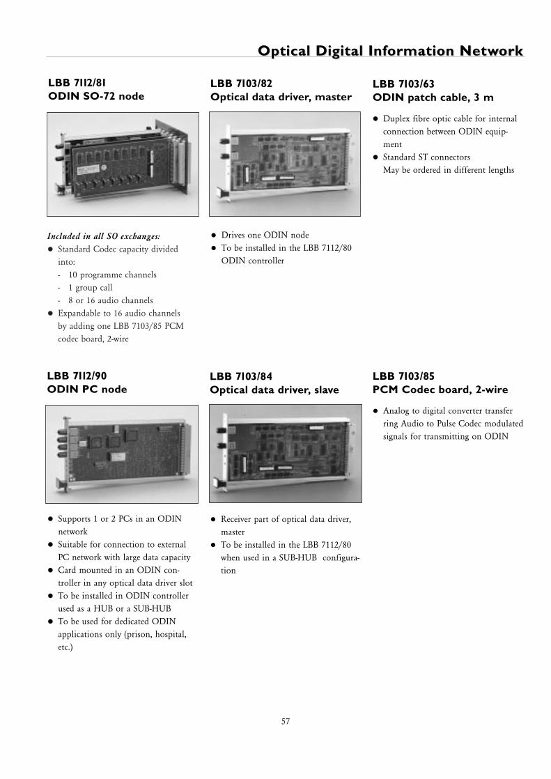
57
Optical Digital Information NetOptical Digital Information Netwworkork
Included in all SO exchanges:ll Standard Codec capacity divided
into:- 10 programme channels- 1 group call- 8 or 16 audio channels
ll Expandable to 16 audio channels by adding one LBB 7103/85 PCM codec board, 2-wire
LBB 7112/81 ODIN SO-72 node
LBB 7112/90 ODIN PC node
ll Supports 1 or 2 PCs in an ODIN network
ll Suitable for connection to external PC network with large data capacity
ll Card mounted in an ODIN con-troller in any optical data driver slot
ll To be installed in ODIN controller used as a HUB or a SUB-HUB
ll To be used for dedicated ODIN applications only (prison, hospital,etc.)
LBB 7103/63ODIN patch cable, 3 m
ll Duplex fibre optic cable for internal connection between ODIN equip-ment
ll Standard ST connectorsMay be ordered in different lengths
LBB 7103/82Optical data driver, master
l Drives one ODIN node l To be installed in the LBB 7112/80
ODIN controller
LBB 7103/84Optical data driver, slave
l Receiver part of optical data driver, master
l To be installed in the LBB 7112/80 when used in a SUB-HUB configura-tion
LBB 7103/85PCM Codec board, 2-wire
l Analog to digital converter transferring Audio to Pulse Codec modulatedsignals for transmitting on ODIN
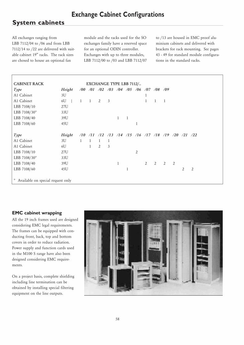
58
System cabinetsSystem cabinetsExchange Cabinet Configurations
All exchanges ranging from LBB 7112/04 to /06 and from LBB7112/14 to /22 are delivered with suit-able cabinet 19� racks. The rack sizesare chosed to house an optional fan
module and the racks used for the SOexchanges family have a reserved spacefor an optional ODIN controller.Exchanges with up to three modules,LBB 7112/00 to /03 and LBB 7112/07
to /13 are housed in EMC proof alu-minium cabinets and delivered withbrackets for rack mounting. See pages43 - 49 for standard module configura-tions in the standard racks.
CABINET RACK EXCHANGE TYPE LBB 7112/..Type Height /00 /01 /02 /03 /04 /05 /06 /07 /08 /09A1 Cabinet 3U 1A1 Cabinet 6U | 1 1 2 3 1 1 1LBB 7108/10 27ULBB 7108/30* 33ULBB 7108/40 39U 1 1LBB 7108/60 45U 1
Type Height /10 /11 /12 /13 /14 /15 /16 /17 /18 /19 /20 /21 /22A1 Cabinet 3U 1 1 1 1A1 Cabinet 6U 1 2 3LBB 7108/10 27U 2LBB 7108/30* 33ULBB 7108/40 39U 1 2 2 2 2LBB 7108/60 45U 1 2 2
* Available on special request only
EMC cabinet wrappingAll the 19 inch frames used are designedconsidering EMC legal requirements.The frames can be equipped with con-ducting front, back, top and bottomcovers in order to reduce radiation.Power supply and function cards usedin the M100 S range have also beendesigned considering EMC require-ments.
On a project basis, complete shieldingincluding line termination can beobtained by installing special filteringequipment on the line outputs.
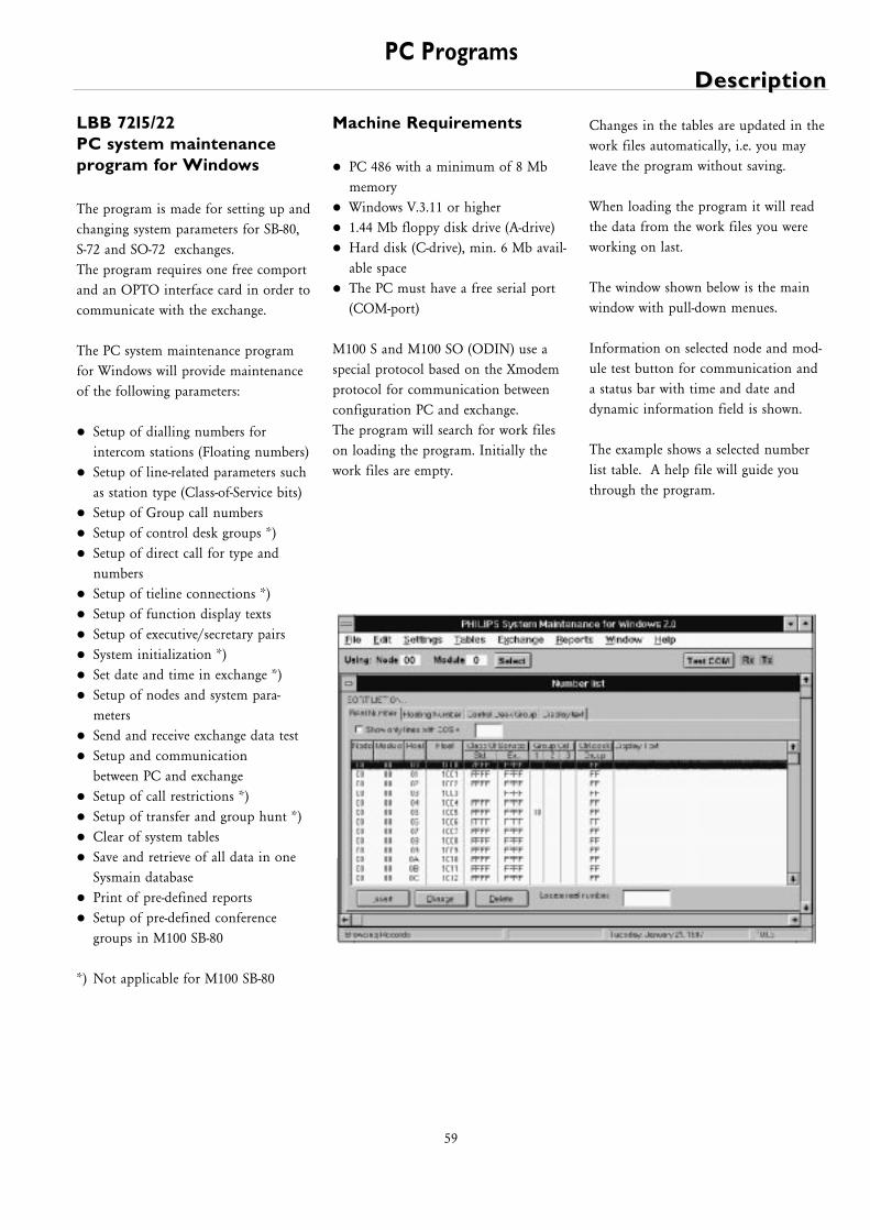
59
DescriptionDescriptionPC Programs
LBB 7215/22PC system maintenanceprogram for Windows
The program is made for setting up andchanging system parameters for SB-80,S-72 and SO-72 exchanges. The program requires one free comportand an OPTO interface card in order tocommunicate with the exchange.
The PC system maintenance programfor Windows will provide maintenanceof the following parameters:
l Setup of dialling numbers for intercom stations (Floating numbers)
l Setup of line-related parameters such as station type (Class-of-Service bits)
l Setup of Group call numbers l Setup of control desk groups *) l Setup of direct call for type and
numbersl Setup of tieline connections *)l Setup of function display textsl Setup of executive/secretary pairsl System initialization *)l Set date and time in exchange *)l Setup of nodes and system para-
metersl Send and receive exchange data testl Setup and communication
between PC and exchangel Setup of call restrictions *)l Setup of transfer and group hunt *)l Clear of system tablesl Save and retrieve of all data in one
Sysmain databasel Print of pre-defined reportsl Setup of pre-defined conference
groups in M100 SB-80
*) Not applicable for M100 SB-80
Machine Requirements
l PC 486 with a minimum of 8 Mb memory
l Windows V.3.11 or higherl 1.44 Mb floppy disk drive (A-drive)l Hard disk (C-drive), min. 6 Mb avail-
able spacel The PC must have a free serial port
(COM-port)
M100 S and M100 SO (ODIN) use aspecial protocol based on the Xmodemprotocol for communication betweenconfiguration PC and exchange.The program will search for work fileson loading the program. Initially thework files are empty.
Changes in the tables are updated in thework files automatically, i.e. you mayleave the program without saving.
When loading the program it will readthe data from the work files you wereworking on last.
The window shown below is the mainwindow with pull-down menues.
Information on selected node and mod-ule test button for communication anda status bar with time and date anddynamic information field is shown.
The example shows a selected numberlist table. A help file will guide youthrough the program.
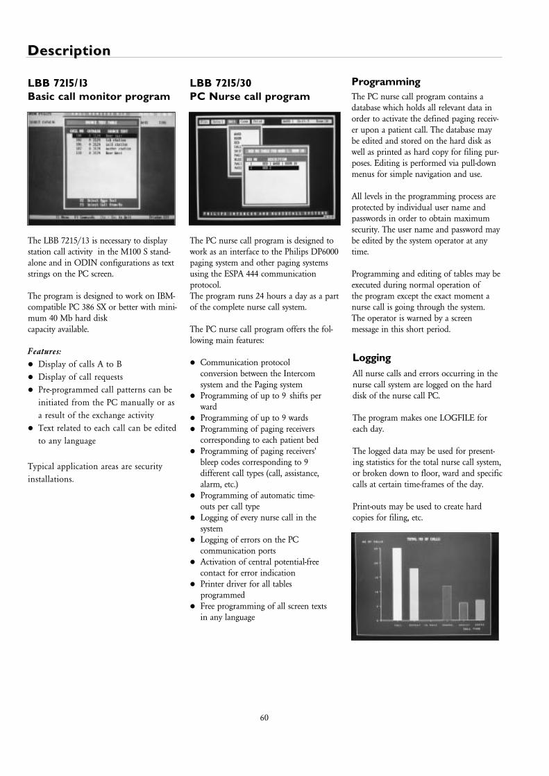
60
DescriptionDescription
LBB 7215/13Basic call monitor program
The LBB 7215/13 is necessary to displaystation call activity in the M100 S stand-alone and in ODIN configurations as textstrings on the PC screen.
The program is designed to work on IBM-compatible PC 386 SX or better with mini-mum 40 Mb hard disk capacity available.
Features:l Display of calls A to Bl Display of call requestsl Pre-programmed call patterns can be
initiated from the PC manually or asa result of the exchange activity
l Text related to each call can be editedto any language
Typical application areas are securityinstallations.
The PC nurse call program is designed towork as an interface to the Philips DP6000paging system and other paging systemsusing the ESPA 444 communication protocol. The program runs 24 hours a day as a partof the complete nurse call system.
The PC nurse call program offers the fol-lowing main features:
l Communication protocol conversion between the Intercom system and the Paging system
l Programming of up to 9 shifts per ward
l Programming of up to 9 wardsl Programming of paging receivers
corresponding to each patient bedl Programming of paging receivers'
bleep codes corresponding to 9 different call types (call, assistance, alarm, etc.)
l Programming of automatic time-outs per call type
l Logging of every nurse call in the system
l Logging of errors on the PC communication ports
l Activation of central potential-free contact for error indication
l Printer driver for all tables programmed
l Free programming of all screen texts in any language
ProgrammingThe PC nurse call program contains adatabase which holds all relevant data inorder to activate the defined paging receiv-er upon a patient call. The database maybe edited and stored on the hard disk aswell as printed as hard copy for filing pur-poses. Editing is performed via pull-downmenus for simple navigation and use.
All levels in the programming process areprotected by individual user name andpasswords in order to obtain maximumsecurity. The user name and password maybe edited by the system operator at anytime.
Programming and editing of tables may beexecuted during normal operation of the program except the exact moment anurse call is going through the system. The operator is warned by a screenmessage in this short period.
LoggingAll nurse calls and errors occurring in thenurse call system are logged on the harddisk of the nurse call PC.
The program makes one LOGFILE foreach day.
The logged data may be used for present-ing statistics for the total nurse call system,or broken down to floor, ward and specificcalls at certain time-frames of the day.
Print-outs may be used to create hardcopies for filing, etc.
LBB 7215/30PC Nurse call program

61
The Bi-Way system enables counter person-nel to give their customers personal servicewhile maintaining security and hygiene.
The Philips Bi-Way system is designed tocater for one-to-one intercom communica-tion between two parties.
Typical applications are banking counters,post office counters, railway ticket coun-ters, gates as well as applications in hospital environments where one-to-onecommunication is required. A number of applications are supportedthrough the flexible and universal design.
The operator�s unit may be placed on thedesk or integrated as a part of an operatorconsole through the optional flush mountframe.
The operator has the choice of micro-phones; handsfree communicationthrough the built-in microphone, anoptional gooseneck microphone installedon the operator�s unit for extreme noiseconditions or, as an alternative, an externalmicrophone as well as a headset withmicrophone.
IntroduIntroductionctionBi-Way Intercom System
The Philips Bi-Way intercom system isdesigned for efficient handsfree loudspeak-ing communication between counter per-sonnel and the public through securityglass or glass partitions.
Security glass and specially built countersprovide protection from violence and van-dalism as well as noise and health prob-lems for those handling money or work-ing in restricted areas.

62
Function descriptionFunction description
The standard Bi-Way position consists ofthe following elements:
- LBB 7026/60 Bi-Way operator's unit- LBB 7026/70 Bi-Way microphone kit- LBB 7026/80 Bi-Way loudspeaker kit- LBB 7102/60 Power Supply 12 V/8 W
This can be ordered under one type-number LBB 7026/65 Bi-Way starter kit.The Bi-Way operator's unit contains all theelectronics for one counter position includ-ing the operator's microphone and loud-speaker. The stylish cabinet can be free standing,wall mounted or flush mounted into atable, desk or counter.The functional keyboard contains four but-tons and four lamps (LEDs).
ON/OFFThe Bi-Way position is switched on bytouching the ON/OFF button. The lampindicates when the position is ON.
In normal working conditions no manualoperation is required once the system isswitched on. The volume in both direc-tions is pre-set per position by screwdriveradjustments accessible from the rear of thecabinet.The three buttons in addition to theON/OFF button are included to take care
of special conditions which may occur during use.
MICROPHONE SELECTOR -- "Microphone selector" button with
lamp for switching to an optional goose-neck microphone fitted to the operator's unit. This enables handsfree communication even in periods of intense noise on the operator's side.
STAND-BY- The "Stand-by" button with lamp to set
the system in listen mode with reduced volume, reduces the ambient noise fromthe public side during waiting periods.
PUSH-TO-TALK- "Push-to-talk" button to amplify the
operator's voice on the public side, enables distinct communication in periods of intense noise, as well as for attracting people at a distance from the counter.It also allows the operator to speak at normal conversational level to people with hearing difficulties.
SIMPLEX- Simplex button. When "Stand-by"
is not selected the "push-to-talk" button will give normal simplex operation without extra amplifica-
tion. Active simplex function is indicated by the corresponding LED.
Screen microphone and loudspeakersOne electret microphone and two loud-speakers are installed on the public side ofthe glass partition. These elements may beattached to the glass, partly concealed orcompletely built into the screen. The stan-dard microphone kit and loudspeaker kitcontain all materials necessary for mount-ing on the public side of one Bi-Way posi-tion.
The microphone and its connecting cablesis concealed in a thin aluminium listattached to the glass screen by means ofself-adhesive tape. The list can easily beadapted to glass partitions of all types.
The compact loudspeakers are attached tothe glass on each side of the microphonelist which may terminate in the loudspeak-ers allowing hidden cabling between thethree elements.
The loudspeakers are also provided withself-adhesive tape but they may also befixed to the frame of the partition, or thewall, by means of screws.
Power supply12 V d.c. Power Supply for up to five Bi-Way positions.
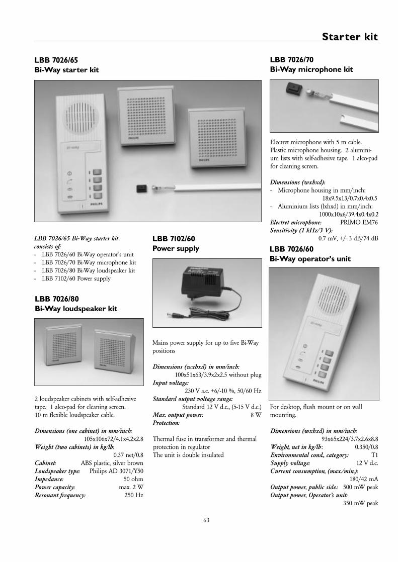
For desktop, flush mount or on wallmounting.
Dimensions (one cabinet) in mm/inch:105x106x72/4.1x4.2x2.8
Weight (two cabinets) in kg/lb:0.37 net/0.8
Cabinet: ABS plastic, silver brownLoudspeaker type: Philips AD 3071/Y50Impedance: 50 ohmPower capacity: max. 2 WResonant frequency: 250 Hz
Dimensions (wxhxd):- Microphone housing in mm/inch:
18x9.5x13/0.7x0.4x0.5- Aluminium lists (lxhxd) in mm/inch:
1000x10x6/39.4x0.4x0.2Electret microphone: PRIMO EM76Sensitivity (1 kHz/3 V):
0.7 mV, +/- 3 dB/74 dB
63
StarStarter kitter kit
LBB 7026/60Bi-Way operator�s unit
Dimensions (wxhxd) in mm/inch:93x65x224/3.7x2.6x8.8
Weight, net in kg/lb: 0.350/0.8 Environmental cond., category: T1Supply voltage: 12 V d.c.Current consumption, (max./min.):
180/42 mAOutput power, public side.: 500 mW peakOutput power, Operator�s unit:
350 mW peak
LBB 7026/70Bi-Way microphone kit
Electret microphone with 5 m cable.Plastic microphone housing. 2 alumini-um lists with self-adhesive tape. 1 alco-padfor cleaning screen.
LBB 7026/80Bi-Way loudspeaker kit
2 loudspeaker cabinets with self-adhesivetape. 1 alco-pad for cleaning screen. 10 m flexible loudspeaker cable.
LBB 7102/60Power supply
Mains power supply for up to five Bi-Waypositions
Dimensions (wxhxd) in mm/inch:100x51x63/3.9x2x2.5 without plug
Input voltage:230 V a.c. +6/-10 %, 50/60 Hz
Standard output voltage range:Standard 12 V d.c., (5-15 V d.c.)
Max. output power: 8 WProtection:
Thermal fuse in transformer and thermal protection in regulatorThe unit is double insulated
LBB 7026/65Bi-Way starter kit
LBB 7026/65 Bi-Way starter kit consists of:- LBB 7026/60 Bi-Way operator�s unit- LBB 7026/70 Bi-Way microphone kit- LBB 7026/80 Bi-Way loudspeaker kit- LBB 7102/60 Power supply

Optional microphone for connection tothe operator's unit to improve flexibility.
Hearing aid loop antenna and amplifier.To be used with 230 V/12 V a.c. 8 Wpower sup-ply with Euro-connector, LBB 7102/63 or 240 V/12 V a.c. 8 Wpower supply with UK-connector, LBB 7102/64.
64
Optional accessoriesOptional accessories
LBB 7073/82Handset with cradle kit
Optional handset for wall mounting indifficult noise conditions or for situationswhere confidentiality is required.
LBB 7026/71Bi-Way goose-neck microphone
LBB 7026/81Bi-Way flush mount loudspeaker kit
Optional loudspeakers for flush mountapplications in desk or wall.Height/diameter in mm/inch:58x160/2.3x6.3Weigh tin kg/lb: 0.700/1.5Frequency range: 130-15000 HzPower: 6 WImpedance: 20 ohm
Optional directional microphone forextreme noise conditions.Height/diameter in mm/inch:
320x12/12.6x0.5Weight in kg/lb: 130/0.3Frequency range: 100-10000 HzSensitivity: 7.2 mV/Pa, +/- 3 dBImpedance: 1000 ohms, +/- 40%
LBB 7026/82Bi-Way hearing aid kit
LBB 7026/72Bi-Way external microphone
LBB 7073/70Flush mount frame
Flush mount frame for operator's unit fordesk or wall.Dimensions (wxhxd) in mm/inch:
130x265x18/5.1x10.4x0.7Cut-out hole in mm/inch:
107x231x63/4.2x9.1x2.5
LBB 7026/83Bi-Way headset
Headset with microphone for connectingto the Bi-Way operator's unit
LBB 7102/63Power supply 12 V, Euro-connector
LBB 7102/64Power supply 12 V, UK-connector
230 V/12 V a.c. 8 W power supply withEuro-connector.
240 V/12 V a.c. 8 W power supply withUK-connector.

65
Standard Requirement Specification
T 1 T 2 T 3 T 4 T 5 E
Standard requirement Indoors in Indoors in light Indoors in Normal Heavy duty Indoors inspecifications - SRS office & light industrial heavy duty outdoor outdoor climate-con-Intercom & Nurse Call industrial & hospital industrial environments environments trolled offices
environments environments environments such as gates, with special and light in- doors, etc. requirements dustrial
environments
1. Mains supply when applicable
90-190 V a.c. 47-63 Hz NA NA NA NA NA X
180-264 V a.c. 47-63 Hz NA NA NA NA NA X
2. Environmental data, operating
2.1 Ambient temperature range (oC):
-25/+55 X X
0/+45 X X X X
2.2 Relative humidity (%):
30-80, non-condensing X
10-95 X X X X X
3. Miscellaneous
3.1 Min. lifetime, installed 10 years X X X X X X
3.2 Max. storage time, 2 years X X X X X X
3.3 Reliability, MTBF
3.3.1 5 years X X
3.3.2 20 years X X X X
3.4 Service (facilities for repair of sub-units):
3.4.1 Local (NSO/installer) X X X X X X
3.4.2 Central (supply centre) X
3.5 Service period 5 years X X X X X X
3.6 Accepted level at delivery, non funct. device, 1,0% X X X X X X
NA = not applicable
66
IP Degree of Protection
Protection for electrical apparatus against physical contact, foreign bodies and ingress of water. The degree of protection is stipulated byusing the abbreviation IP (international protection) and two identification numbers according to the following table.
Degree of protection (Protection against contact and ingress of solid foreign bodies)
0 No special protection.1 Protection against ingress of solid objects with a diameter of more than 50 mm (large foreign bodies). 1)
No protection against deliberate access, for example with a hand, but large surfaces of the body areprevented from approach.
2 Protection against penetration by solid objects with a diameter of more than 12 mm (medium-size objects). 1)3 Protection against ingress of solid objects with a diameter of more than 2.5 mm (small foreign bodies). 1) 2)
Tools, wires, etc., with a thickness of more than 2.5 mm are prevented from approach.4 Protection against ingress of solid objects with a diameter of more than 1 mm (granular objects). 1) 2)
Tools, wires, etc., of thickness greater than 1 mm are prevented from approach.5 Protection against harmful dust deposits. Ingress of dust is not totally prevented but the dust must not enter
in sufficient quantity as to interfere with satisfactory operation of the equipment (dust protected). 3)Complete protection against contact.
6 Protection against ingress of dust (dust-tight).Complete protection against contact.
1) In the case of equipment with a degree of protection from 1 to 4, uniformly or non-uniformly shaped foreign bodies with three mutually perpendicular dimensions greater than the numericalvalues given for the diameter are prevented from ingress.
2) For degree of protection 3 and 4, the application of this table for equipment containing drainage holes or ventilation openings is the responsibility of the relevant technical committee.
3) For degree of protection 5, the application of this table for equipment containing drainage holes is theresponsibility of the relevant technical committee.
Degree of protection (Protection against ingress of water)
0 No special protection.1 Protection against dripping water at an angle.
No harmful effect must be produced (vertically falling drops).2 Protection against dripping water falling vertically.
There must be no harmful effect when the equipment (enclosure) is tilted at an angle up to 15o
from its normal position (drops falling at an angle).3 Protection against water falling at any angle up to 60o from the vertical.
There must be no harmful effect (spray water).4 Protection against water splashed against the equipment (enclosure) from any direction.
There must be no harmful effect (splashing water).5 Protection against water projected from a nozzle against the equipment (enclosure) from any direction.
There must be no harmful effect (water jet).6 Protection against heavy seas or powerful water jets.
Water must not enter the equipment (enclosure) in harmful quantities (splashing over).7 Protection against water when the equipment (enclosure) is immersed in water under defined conditions
of pressure and time.Water must not enter in harmful quantities (immersion).
8 The equipment (enclosure) is suitable for continuous submersion in water under conditions which mustbe specified by the manufacturer (submersion). 1)
1) This degree of protection normally means that the equipment is hermetically sealed. However, with certain types of equipment it can mean that water may enter, provided it produces no harmful effects.

67
Typenumber Survey
Typenumber Description Page
LBB 7026/60 Bi-Way operator's unit . . . . . . . . . . . . . . . .63LBB 7026/65 Bi-Way starter kit . . . . . . . . . . . . . . . . . . . .63LBB 7026/70 Bi-Way microphone kit . . . . . . . . . . . . . . .63LBB 7026/71 Bi-Way gooseneck microphone . . . . . . . . .64LBB 7026/72 Bi-Way external microphone . . . . . . . . . . .64LBB 7026/80 Bi-Way loudspeaker kit . . . . . . . . . . . . . . .63LBB 7026/81 Bi-Way flush-mount loudspeaker kit . . . . .64LBB 7026/82 Bi-Way hearing aid kit . . . . . . . . . . . . . . . .64LBB 7026/83 Bi-Way headset . . . . . . . . . . . . . . . . . . . . . .64LBB 7069/08 Wall socket, 6 pole, 10 pack . . . . . . . . . . .19LBB 7069/18 6-pole plug, male 10 pack . . . . . . . . . . . . .19LBB 7069/21 Wall socket, snap in, 4-pole 10 pack . . . . .19LBB 7069/62 Station cord, snap-in connector 10 pack . .19LBB 7069/63 Station cord, 6-pole connector 10 pack . . .19LBB 7069/64 Station cord interconn, 4-pole 10 pack . . .19LBB 7071/10 Flame-proof loudspeaker horn,
8 W/8 Ohm . . . . . . . . . . . . . . . . . . . . . . .12LBB 7071/71 Heavy duty handset kit . . . . . . . . . . . . . . .18LBB 7072/10 Master station kit . . . . . . . . . . . . . . . . . . . .15LBB 7072/32 Single/Dual call station kit . . . . . . . . . . . .15LBB 7073/60 On wall back box . . . . . . . . . . . . . . . . . . .18LBB 7073/61 Flush mount back box, 60 mm . . . . . . . . .18LBB 7073/62 On wall back box, plastic . . . . . . . . . . . . .19LBB 7073/63 Flush mount back box, 75 mm . . . . . . . . .19, 28LBB 7073/65 Audio/Relay kit . . . . . . . . . . . . . . . . . . . . .16LBB 7073/66 Audio kit . . . . . . . . . . . . . . . . . . . . . . . . . .16LBB 7073/67 Relay kit . . . . . . . . . . . . . . . . . . . . . . . . . .17LBB 7073/68 Application kit . . . . . . . . . . . . . . . . . . . . .17LBB 7073/70 Flush mount frame . . . . . . . . . . . . . . . . . .18, 64LBB 7073/71 Flush mount frame, white . . . . . . . . . . . . .28LBB 7073/73 Weather protection frame . . . . . . . . . . . . .18LBB 7073/74 Outdoor station heating kit . . . . . . . . . . . .19LBB 7073/80 Desktop handset kit . . . . . . . . . . . . . . . . . .18LBB 7073/82 Handset with cradle kit . . . . . . . . . . . . . . .18, 64LBB 7073/84 Cradle bracket . . . . . . . . . . . . . . . . . . . . . .18LBB 7076/26 Red lamp terminal glass . . . . . . . . . . . . . .29LBB 7076/27 Green lamp terminal glass . . . . . . . . . . . . .29LBB 7076/28 White lamp terminal glass . . . . . . . . . . . . .29LBB 7076/29 Yellow lamp terminal glass . . . . . . . . . . . .29LBB 7076/37 Blue lamp terminal glass . . . . . . . . . . . . . .29LBB 7076/60 Terminal cover plate . . . . . . . . . . . . . . . . .28LBB 7076/61 Terminal housing, single . . . . . . . . . . . . . .28LBB 7076/62 Terminal housing, dual . . . . . . . . . . . . . . .28LBB 7076/63 Terminal housing, triple . . . . . . . . . . . . . .28LBB 7076/75 Bi-stable control relay . . . . . . . . . . . . . . . .28LBB 7077/00 PAN controller plug-in board . . . . . . . . . .24LBB 7077/10 Bedside station . . . . . . . . . . . . . . . . . . . . . .24LBB 7077/20 Dual lamp terminal, 4-wire . . . . . . . . . . . .29LBB 7077/21 Dual lamp terminal, 4-wire
with buzzer . . . . . . . . . . . . . . . . . . . . . . . .29LBB 7077/22 Triple lamp terminal, 4-wire . . . . . . . . . . .29LBB 7077/25 PAN lamp terminal, single . . . . . . . . . . . .28
Typenumber Description Page
LBB 7077/26 PAN lamp terminal, dual . . . . . . . . . . . . .28LBB 7077/30 Patient remote control . . . . . . . . . . . . . . . .26LBB 7077/31 Patient remote audio . . . . . . . . . . . . . . . . .26LBB 7077/32 Patient remote audio & TV . . . . . . . . . . . .26LBB 7077/33 Patient remote call & light . . . . . . . . . . . . .26LBB 7077/35 Pull-cord terminal . . . . . . . . . . . . . . . . . . .26LBB 7077/36 Cradle for remote control . . . . . . . . . . . . .25LBB 7077/40 Presence, assistance & alarm terminal . . . .26LBB 7077/41 Presence & assistance terminal . . . . . . . . . .26LBB 7077/42 Precence terminal . . . . . . . . . . . . . . . . . . . .27LBB 7077/43 Precence & alarm terminal . . . . . . . . . . . . .27LBB 7077/44 Call button terminal . . . . . . . . . . . . . . . . .27LBB 7077/45 Patient remote terminal . . . . . . . . . . . . . . .27LBB 7077/50 Dual external alarm terminal . . . . . . . . . . .27LBB 7077/51 Alarm terminal - heavy duty . . . . . . . . . . .27LBB 7077/70 Cord saver - RJ45 . . . . . . . . . . . . . . . . . . . .25LBB 7077/71 PAN TV interface . . . . . . . . . . . . . . . . . . .26LBB 7089/10 Desktop master station . . . . . . . . . . . . . . .5LBB 7089/15 Compact master station . . . . . . . . . . . . . . .5LBB 7089/16 Compact master display station . . . . . . . . .6LBB 7089/18 Compact master display station
w/back light . . . . . . . . . . . . . . . . . . . . . . . .6LBB 7089/20 Industrial master station . . . . . . . . . . . . . .8LBB 7089/21 Industrial single call station . . . . . . . . . . . .9LBB 7089/22 Industrial dual call station . . . . . . . . . . . . .9LBB 7089/24 Industrial call stn. 4 button . . . . . . . . . . . .9LBB 7089/26 Industrial call stn. 6 button . . . . . . . . . . . .9LBB 7089/28 Emergency station w/key release . . . . . . . .13LBB 7089/30 Industrial master display station
w/back light . . . . . . . . . . . . . . . . . . . . . . . .8LBB 7089/31 Single call station . . . . . . . . . . . . . . . . . . . .7LBB 7089/32 Dual call station . . . . . . . . . . . . . . . . . . . .7LBB 7089/40 Heavy duty master station . . . . . . . . . . . . .10LBB 7089/41 Heavy duty single call station . . . . . . . . . .11LBB 7089/42 Heavy duty dual call station . . . . . . . . . . .11LBB 7089/50 Explosion-proof master station IIC . . . . . .12LBB 7089/52 Explosion-proof dual call station IIC . . . .12LBB 7089/96 Chemical resistant master station . . . . . . .13LBB 7089/97 Programme distribution station . . . . . . . . .13LBB 7095/01 Power supply 24 V/40 W -
Euro connector . . . . . . . . . . . . . . . . . . . . .19LBB 7102/18 S-16 power supply 36 V/1,7 A - EMC . . . .36LBB 7102/60 Power supply 12 V/8 W . . . . . . . . . . . . . . .63LBB 7102/63 Power supply 12 V, Euro-connector . . . . . .64LBB 7102/64 Power supply 12 V, UK-connector . . . . . . .64LBB 7102/87 +/- 12 V DC/DC converter . . . . . . . . . . . .54LBB 7103/48 MK II Voice board . . . . . . . . . . . . . . . . . .53LBB 7103/56 ACIA card . . . . . . . . . . . . . . . . . . . . . . . .54LBB 7103/61 OPTO cable, 4 m . . . . . . . . . . . . . . . . . . .54LBB 7103/62 Serial interface cable, 4 m . . . . . . . . . . . . .54LBB 7103/63 ODIN Patch cable, 3 m . . . . . . . . . . . . . . .57LBB 7103/82 Optical data driver, master . . . . . . . . . . . .57
68
Typenumber Survey
Typenumber Description Page
LBB 7103/84 Optical data driver, slave . . . . . . . . . . . . . .57LBB 7103/85 PCM codec board, 2-wire . . . . . . . . . . . . . .57LBB 7105/95 Line termination unit . . . . . . . . . . . . . . . .53LBB 7105/97 Line termination cable, 16 lines . . . . . . . . .53LBB 7105/98 Line termination panel . . . . . . . . . . . . . . .53LBB 7108/10 Cabinet 27U . . . . . . . . . . . . . . . . . . . . . . .58LBB 7108/30 Cabinet 33U . . . . . . . . . . . . . . . . . . . . . . .58LBB 7108/40 Cabinet 39U . . . . . . . . . . . . . . . . . . . . . . .58LBB 7108/60 Cabinet 45U . . . . . . . . . . . . . . . . . . . . . . .58LBB 7109/21 VDU terminal opto interface . . . . . . . . . . .54LBB 7109/23 PC opto interface card, plastic fibre . . . . . .54LBB 7109/24 PC opto interface card, glass fibre . . . . . . .54LBB 7109/26 S-80 programming kit . . . . . . . . . . . . . . . .43LBB 7110/08 DTMF coupler, 4 lines . . . . . . . . . . . . . . .55LBB 7110/09 FSK coupler, 2 lines . . . . . . . . . . . . . . . . . .55LBB 7110/29 Line card for 6 stations/2simplex
relay loudspeakers . . . . . . . . . . . . . . . . . . .53LBB 7110/30 Line card, 8 stations 10 programmes . . . . .53LBB 7110/39 Line card 10 programmes 6 stations/
2 coupler lines . . . . . . . . . . . . . . . . . . . . . .53LBB 7110/40 Line card, 8 simplex relay loudspeakers . . .53LBB 7110/45 Line card, 8 stations 10 programme
channels/open line check . . . . . . . . . . . . .53LBB 7110/47 Line card for 6 stations/2 coupler
lines/open line check . . . . . . . . . . . . . . . . .53LBB 7110/48 DTMF Telephone coupler, 2 lines . . . . . . .55LBB 7111/00 S-16 Basic exchange . . . . . . . . . . . . . . . . . .34LBB 7111/16 S-16 Start pack compl. w/3 stations . . . . . .35LBB 7111/17 S-16 Start pack compl. w/8 stations . . . . . .35LBB 7111/18 S-16 Start pack w/3 stations snap-in . . . . . .35LBB 7111/19 S-16 Start pack display w/3 stations
snap-in . . . . . . . . . . . . . . . . . . . . . . . . . . . .35LBB 7111/20 S-16 Line card for 2 stations . . . . . . . . . . .36LBB 7111/22 S-16 Line card 1 station/1 loudspeaker . . .36LBB 7111/32 S-16 Power distribution board . . . . . . . . . .36LBB 7111/50 Interconnection kit two S-16 exchanges . . .36LBB 7111/51 S-16 Display driver kit . . . . . . . . . . . . . . . .36LBB 7112/00 SB-80 Exchange . . . . . . . . . . . . . . . . . . . . .43LBB 7112/01 S-72 Exchange . . . . . . . . . . . . . . . . . . . . . .44LBB 7112/02 S-144 Exchange . . . . . . . . . . . . . . . . . . . . .44LBB 7112/03 S-216 Exchange . . . . . . . . . . . . . . . . . . . . .44LBB 7112/04 S-256 Exchange . . . . . . . . . . . . . . . . . . . . .45LBB 7112/05 S-320 Exchange . . . . . . . . . . . . . . . . . . . . .45LBB 7112/06 S-384 Exchange . . . . . . . . . . . . . . . . . . . . .45LBB 7112/08 S-72 Sub Exchange . . . . . . . . . . . . . . . . . . .51LBB 7112/09 S-64 Sub Exchange . . . . . . . . . . . . . . . . . . .51LBB 7112/11 SO-72 Exchange . . . . . . . . . . . . . . . . . . . . .46LBB 7112/12 SO-144 Exchange . . . . . . . . . . . . . . . . . . . .46LBB 7112/13 SO-216 Exchange . . . . . . . . . . . . . . . . . . . .46LBB 7112/14 SO-256 Exchange . . . . . . . . . . . . . . . . . . . .47LBB 7112/15 SO-320 Exchange . . . . . . . . . . . . . . . . . . . .47LBB 7112/16 SO-384 Exchange . . . . . . . . . . . . . . . . . . . .47
Typenumber Description Page
LBB 7112/17 SO-448 Exchange . . . . . . . . . . . . . . . . . . . .48LBB 7112/18 SO-512 Exchange . . . . . . . . . . . . . . . . . . . .48LBB 7112/19 SO-576 Exchange . . . . . . . . . . . . . . . . . . . .48LBB 7112/20 SO-640 Exchange . . . . . . . . . . . . . . . . . . . .49LBB 7112/21 SO-704 Exchange . . . . . . . . . . . . . . . . . . . .49LBB 7112/22 SO-768 Exchange . . . . . . . . . . . . . . . . . . . .49LBB 7112/30 SB-80/S-72 Function upgrade kit . . . . . . . .51LBB 7112/31 SB-80/SO-72 ODIN function
upgrade kit . . . . . . . . . . . . . . . . . . . . . . . .51LBB 7112/32 S-72/SO-72 ODIN function upgrade kit . .52LBB 7112/33 S-216/S-256 Stand-alone exchange
expansion kit . . . . . . . . . . . . . . . . . . . . . . .52LBB 7112/34 SO-320/SO-384 ODIN exchange
expansion kit . . . . . . . . . . . . . . . . . . . . . . .52LBB 7112/60 DP6000 paging coupler . . . . . . . . . . . . . . .55LBB 7112/80 ODIN Controller . . . . . . . . . . . . . . . . . . .56LBB 7112/81 ODIN SO-72 Node . . . . . . . . . . . . . . . . . .57LBB 7112/90 ODIN PC Node . . . . . . . . . . . . . . . . . . . .57LBB 7201/01 S-16 function package . . . . . . . . . . . . . . . .41LBB 7201/10 S-16 13 subs/2 masters program . . . . . . . .37LBB 7201/11 S-16 8 subs/2 masters program . . . . . . . . .37LBB 7201/12 S-16 10 subs/2 masters display program . .37LBB 7201/30 S-16 PC patch program . . . . . . . . . . . . . . .37LBB 7215/13 Basic call monitor program . . . . . . . . . . . .60LBB 7215/22 PC System maintenance program
for Windows . . . . . . . . . . . . . . . . . . . . . . .59LBB 7215/30 PC Nurse call program . . . . . . . . . . . . . . .60LBB 7216/11 SB-80 Basic function package . . . . . . . . . .41LBB 7216/22 Single node function package - 6 digit . . . .41LBB 7216/82 ODIN function package . . . . . . . . . . . . . .41LBB 7999/35 M100 S P.A. coupler . . . . . . . . . . . . . . . . .16LBC 3490/10 Loudspeaker horn, 16 ohm . . . . . . . . . . . .10

Dokument1 18-05-98 20:50 Side 1

PhilipsCommunication &Security Systems
All round expertise
Philips leads the way with total solutions for
communications and security applications. Dedicated expertise in
access control, closed-circuit TV, congress, intercom, paging and
public address means even the most demanding requirements
can be met. Compability and flexibility are guaranteed by the
integrated system approach.
The high-quality products from Philips Communications
& Security Systems are backed up with comprehensive
maintenance, service and training support. And with a wealth of
experience in transport, industrial, commercial, healthcare, leisure
and retail applications, you can be sure that communications
channels will stay open, and personnel and property remain safe.
Dat
a su
bjec
t to
cha
nge
with
out
notic
e.
392
4 98
1 15
511
09/
97
©P
hilip
s E
lect
roni
cs N
.V.
1997
PhilipsCommunication &Security Systems
08704-intercom-oms.qxd 18-05-98 19:49 Side 1