Secure Access Configuration Guide For Wireless...
60
ProCurve Networking Secure Access Configuration Guide For Wireless Clients Part Two: Wireless Data Privacy and Monitored Logon Secure Access Configuration Guide For Wireless Clients .................... 2 Introduction ......................................................................................................... 2 Configuration Scenarios ......................................................................................... 2 Required Network Services ..................................................................................... 2 Basic Setup and Topology....................................................................................... 3 Software Versions ................................................................................................. 4 Getting Started ..................................................................................................... 4 Step 1: Configuring the Switch 5300xl ..................................................................... 4 Step 2: Configuring the Access Control Server 740wl ................................................. 5 Step 3: Configuring the Access Control xl Module....................................................... 5 Step 4: Configuring the Access Point 420.................................................................. 5 Configuring Scenario 4: Wireless Data Privacy Logon using VPN Authentication (PPTP) .... 8 Configuring Scenario 5: Wireless Data Privacy Logon using VPN Authentication (L2TP/IPSec) .............................................................. 23 Configuring Scenario 6: Monitored Logon 802.1x Authentication ................................. 44 © Copyright 2005 Hewlett-Packard Company, LP.
Transcript of Secure Access Configuration Guide For Wireless...
ProCurve Networking
Secure Access Configuration Guide For Wireless Clients Part Two: Wireless Data Privacy and Monitored Logon
Secure Access Configuration Guide For Wireless Clients ....................2 Introduction ......................................................................................................... 2 Configuration Scenarios ......................................................................................... 2 Required Network Services ..................................................................................... 2 Basic Setup and Topology....................................................................................... 3 Software Versions ................................................................................................. 4 Getting Started..................................................................................................... 4 Step 1: Configuring the Switch 5300xl ..................................................................... 4 Step 2: Configuring the Access Control Server 740wl ................................................. 5 Step 3: Configuring the Access Control xl Module....................................................... 5 Step 4: Configuring the Access Point 420.................................................................. 5 Configuring Scenario 4: Wireless Data Privacy Logon using VPN Authentication (PPTP) .... 8 Configuring Scenario 5: Wireless Data Privacy Logon using VPN Authentication (L2TP/IPSec) .............................................................. 23 Configuring Scenario 6: Monitored Logon 802.1x Authentication ................................. 44
© Copyright 2005 Hewlett-Packard Company, LP.
Secure Access Configuration Guide For Wireless Clients
Introduction This document is Part Two of a guide that details the configuration steps for building Secure Access Solutions for Wireless Clients. Part Two of this guide creates solutions for clients using wireless data privacy or monitored logons. Part One creates solutions for clients using a browser-based logon.
The following ProCurve Networking by HP products are used:
• ProCurve Access Control Server 740wl (J8154A) • ProCurve Access Point 420 (J8130A) • ProCurve Access Control xl Module (J8162A) • ProCurve Switch 5300xl (J4850A)
Configuration Scenarios This table defines the configuration scenarios covered in Part Two of this guide.
Scenario Secure Access Method
Airwave Security
IP address Authentication Client OS
1 Browser-based Logon
Static WEP NAT Built-in Database
Windows XP
2 Browser-based Logon
WPA-PSK Real IP LDAP Windows XP
3 Browser-based Logon
Static WEP Real IP RADIUS Windows 2000
4 Wireless Data Privacy Logon
PPTP VPN NAT VPN Windows XP
5 Wireless Data Privacy Logon
L2TP/IPSec NAT/Real IP VPN Windows XP
6 Monitored Logon (802.1x)
Dynamic WEP/802.1x
Real IP Active Directory /RADIUS
Windows XP
Required Network Services The configuration scenarios in the guide require the network services noted below, however, complete server installation and configuration are not shown here with the exception of specific changes required by the configuration scenario. Refer to product documentation for more information.
Microsoft 2003 Enterprise Server with the following running services:
• Microsoft Internet Authentication Service (IAS) • Domain Controller • Certificate Authority • DHCP • DNS • Wins • RRAS
© Copyright 2005 Hewlett-Packard Company, LP. 2
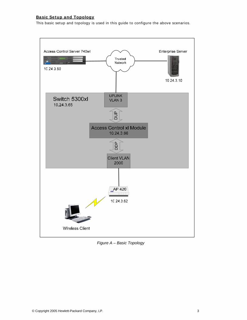
Basic Setup and Topology This basic setup and topology is used in this guide to configure the above scenarios.
Figure A – Basic Topology
© Copyright 2005 Hewlett-Packard Company, LP. 3
Software Versions The table below details the software versions used for the ProCurve network equipment in this guide. For the latest software versions or more info, visit the ProCurve Networking by HP Web site (http://www.procurve.com).
Device Version
Switch 5300xl E.09.21
Access Control xl Module 4.1.3.93
Access Control Server 740wl 4.1.3.93
Access Point 420 2.0.38
Getting Started Getting started with the configuration scenarios in this guide requires completion of steps 1 through 4 below to get the infrastructure prepared.
To get started, refer to the Basic Setup and Topology (Figure A) and complete the following tasks:
• Step 1: Configuring the Switch 5300xl • Step 2: Configuring the Access Control Server 740wl • Step 3: Configuring the Access Control xl Module • Step 4: Configuring the Access Point 420
After completing Steps 1-4, then proceed to the desired Configuration Scenario.
Step 1: Configuring the Switch 5300xl In this example configuration, the Access Control xl Module (ACM) is inserted into slot D of the Switch 5300xl. However, any open 5300xl switch slot may be used. For example, if the ACM is inserted in slot A, the uplink port designation would be “aup”.
Power up the switch, insert the ACM, connect a serial console cable and configure the following at the Switch 5300xl CLI:
1. Configure the default gateway on the switch. 2. Configure an uplink VLAN (vlan 3), IP address and subnet mask 3. Add a port (a1) to the uplink VLAN. 4. Add the ACM uplink port (dup) to the uplink VLAN (vlan 3). 5. Add a port (b1) to VLAN 2000.
Note: Upon insertion of the ACM into the Switch 5300xl, VLAN 2000 is automatically created by default and the downlink port (ddp) is added to this VLAN as a tagged member.
5300xl> en
5300xl# config term
5300xl(config)# ip default-gateway 10.24.3.1
5300xl(config)# vlan 3
5300xl(vlan-3)# ip address 10.24.3.65/24
5300xl(vlan-3)# untag a1
5300xl(vlan-3)# untag dup
5300xl(vlan-3)# vlan 2000
5300xl(vlan-2000)# untag b1
© Copyright 2005 Hewlett-Packard Company, LP. 4
Step 2: Configuring the Access Control Server 740wl This example uses an Access Control Server 740wl. The configuration steps are the same if you are using an Integrated Access Manager 760wl.
Power up the ACS, connect a serial console cable and configure the following at the ACS CLI:
1. Configure an IP address, subnet mask and default gateway. 2. Configure the shared secret (secret).
HP 700wl Series@[42.0.0.1]: set ip 10.24.3.50 255.255.255.0
HP 700wl Series@[10.24.3.50]: set gateway 10.24.3.1
HP 700wl Series@[10.24.3.50]: set sharedsecret secret secret
Step 3: Configuring the Access Control xl Module To configure the ACM, go to the Switch 5300xl CLI and configure the following:
1. Enter the Access Controller configuration context. 2. Set the IP address, subnet mask and default gateway of the ACM. 3. Set the IP address of the Access Control Server 740wl that will be used to manage
the ACM. 4. Set the shared secret (secret) to match the configuration on the ACS.
5300xl> en
5300xl# config term
5300xl(config)# access-controller d
5300xl(access-controller-D)# enable extended-commands
5300xl(access-controller-D-ext)# set ip 10.24.3.66/24
5300xl(access-controller-D-ext)# set gateway 10.24.3.1
5300xl(access-controller-D-ext)# set accesscontrolserver 10.24.3.50
5300xl(access-controller-D-ext)# set sharedsecret secret secret
Use the “show status” command to verify that the ACM is connected to the ACS.
5300xl(access-controller-D-ext)# show status
Uptime: 1 hr, 7 mins.
Access Controller Function
Access Control Server: 10.24.3.50
Connected: 10 mins, 27 secs
Active Clients: 0
Total Sessions: 0
Step 4: Configuring the Access Point 420 Initial configuration of the Access Point 420 for this guide requires two tasks be completed.
1. Configuring the Access Point for general network and wireless Connect a serial console cable to the AP 420 and configure the following at the AP 420 CLI:
• IP address, subnet mask and gateway.
© Copyright 2005 Hewlett-Packard Company, LP. 5
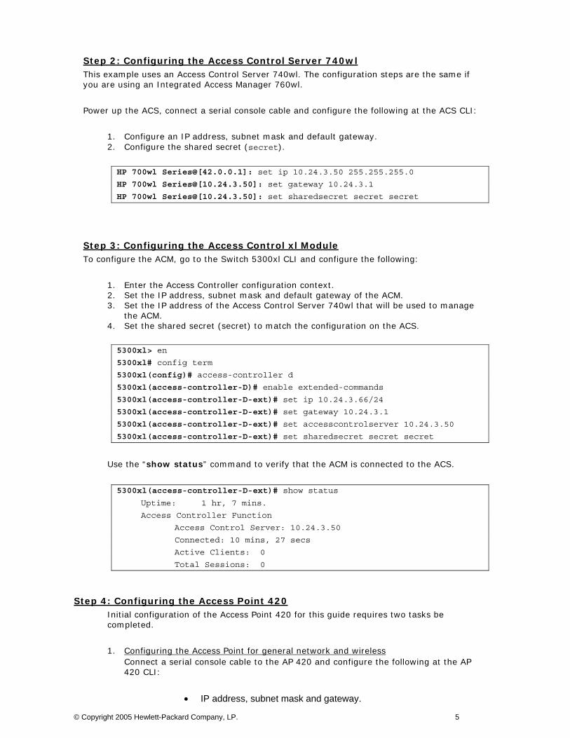
• Enable the Access Point radio • Wireless SSID (x52800cb2) and channel (6).
HP ProCurve Access Point 420# configure Enter configuration commands, one per line. End with CTRL/Z HP ProCurve Access Point 420(config)# int eth Enter Ethernet configuration commands, one per line. HP ProCurve Access Point 420(if-ethernet)# no ip dhcp HP ProCurve Access Point 420(if-ethernet)# ip addr 10.24.3.62 255.255.255.0 10.24.3.1 HP ProCurve Access Point 420(if-ethernet)# end HP ProCurve Access Point 420(config)# int wireless g Enter Wireless configuration commands, one per line. HP ProCurve Access Point 420(if-wireless g)# no shut HP ProCurve Access Point 420(if-wireless g)# ssid x52800cb2 HP ProCurve Access Point 420(if-wireless g)# channel 6
2. Configuring the ACS to recognize the AP 420 as “Network Equipment” Connect the AP 420 to the network (see Figure A) and open the Web browser management interface to the ACS. Enter the username and password (default shown here) of the ACS:
Username: admin
Password: admin
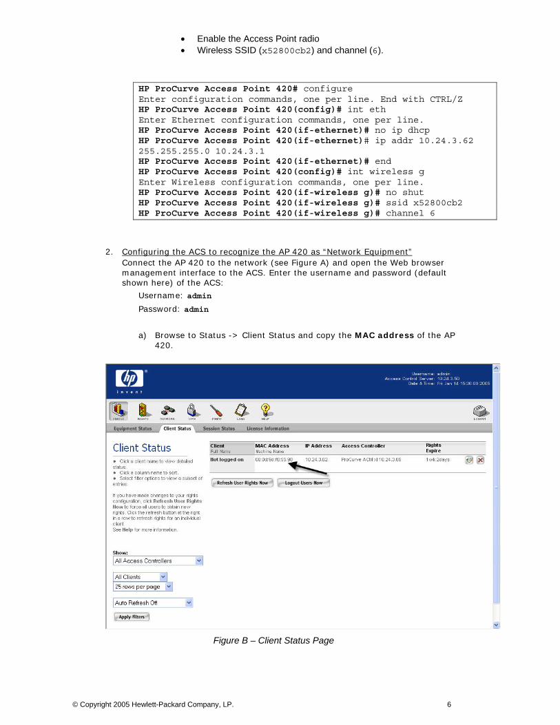
a) Browse to Status -> Client Status and copy the MAC address of the AP 420.
Figure B – Client Status Page
© Copyright 2005 Hewlett-Packard Company, LP. 6
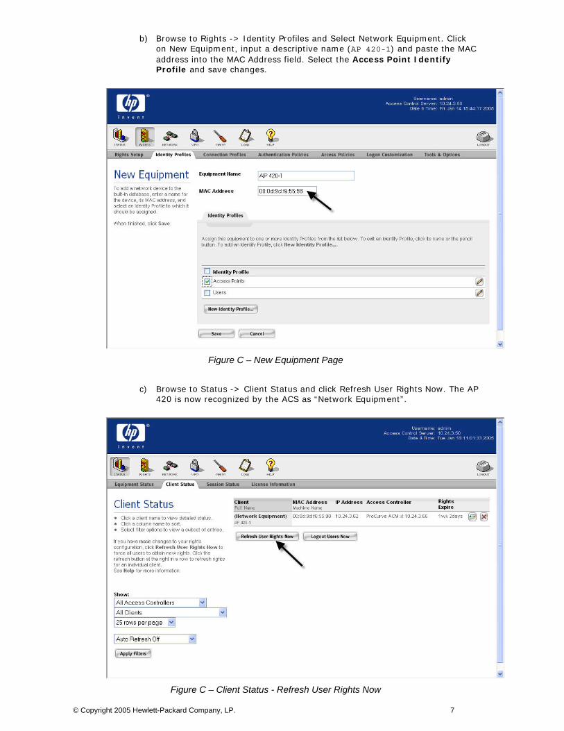
b) Browse to Rights -> Identity Profiles and Select Network Equipment. Click on New Equipment, input a descriptive name (AP 420-1) and paste the MAC address into the MAC Address field. Select the Access Point Identify Profile and save changes.
Figure C – New Equipment Page
c) Browse to Status -> Client Status and click Refresh User Rights Now. The AP 420 is now recognized by the ACS as “Network Equipment”.
Figure C – Client Status - Refresh User Rights Now
© Copyright 2005 Hewlett-Packard Company, LP. 7
Configuring Scenario 4: Wireless Data Privacy Logon using VPN Authentication (PPTP) Scenario 4 consists of a wireless, Windows XP client authenticating via a VPN. The VPN used in this example will be a PPTP VPN. Since VPN authentication requires a RADIUS backend, we will configure the ACS to authenticate VPN users against Internet Authentication Service (IAS), Microsoft’s RADIUS implementation. In contrast to Browser-based logon, Wireless Data Privacy logon is automatic upon successful establishment of the VPN connection. The steps required are:
• On the ACS, enable PPTP VPN support globally. • On the ACS, enable PPTP VPN support in both the Unauthenticated and
Authenticated Access Policies. • On the ACS, define a RADIUS Authentication Service, associate it to the System
Authentication Policy, and enable the RADIUS server to authenticate the user during PPTP session negotiation.
• On the AP 420, configure open authentication wireless parameters. • On the Windows XP client, connect the wireless client, configure PPTP client software
(Windows XP native) and verify authentication.
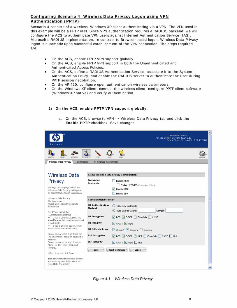
1) On the ACS, enable PPTP VPN support globally.
a. On the ACS, browse to VPN -> Wireless Data Privacy tab and click the Enable PPTP checkbox. Save changes.
Figure 4.1 – Wireless Data Privacy
© Copyright 2005 Hewlett-Packard Company, LP. 8
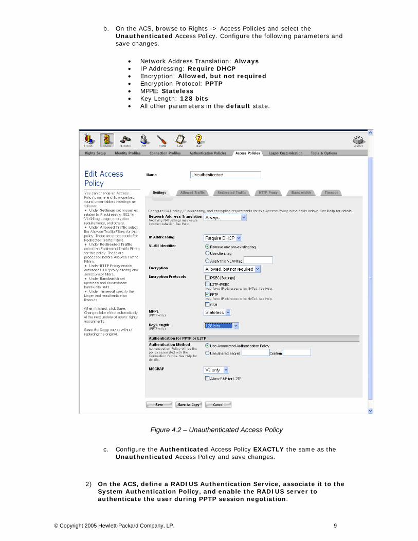
b. On the ACS, browse to Rights -> Access Policies and select the Unauthenticated Access Policy. Configure the following parameters and save changes.
• Network Address Translation: Always • IP Addressing: Require DHCP • Encryption: Allowed, but not required • Encryption Protocol: PPTP • MPPE: Stateless • Key Length: 128 bits • All other parameters in the default state.
Figure 4.2 – Unauthenticated Access Policy
c. Configure the Authenticated Access Policy EXACTLY the same as the Unauthenticated Access Policy and save changes.
2) On the ACS, define a RADIUS Authentication Service, associate it to the System Authentication Policy, and enable the RADIUS server to authenticate the user during PPTP session negotiation.
© Copyright 2005 Hewlett-Packard Company, LP. 9
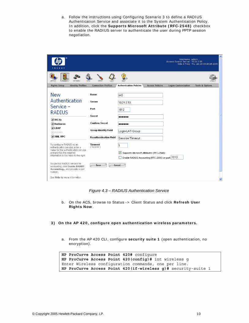
a. Follow the instructions using Configuring Scenario 3 to define a RADIUS Authentication Service and associate it to the System Authentication Policy. In addition, click the Supports Microsoft Attribute (RFC-2548) checkbox to enable the RADIUS server to authenticate the user during PPTP session negotiation.
Figure 4.3 – RADIUS Authentication Service
b. On the ACS, browse to Status -> Client Status and click Refresh User Rights Now.
3) On the AP 420, configure open authentication wireless parameters.
a. From the AP 420 CLI, configure security suite 1 (open authentication, no encryption).
HP ProCurve Access Point 420# configure HP ProCurve Access Point 420(config)# int wireless g Enter Wireless configuration commands, one per line. HP ProCurve Access Point 420(if-wireless g)# security-suite 1
© Copyright 2005 Hewlett-Packard Company, LP. 10

4) On the Windows XP client, connect the wireless client, configure PPTP client software (Windows XP native) and verify authentication.
a. Connect the wireless Windows XP client to the AP 420 using open authentication/no encryption.
b. On the Windows XP client, open the Network connections window and click Create a new connection.
Figure 4.4 – Network Connections
c. Click Next to start the New Connection Wizard.
© Copyright 2005 Hewlett-Packard Company, LP. 11
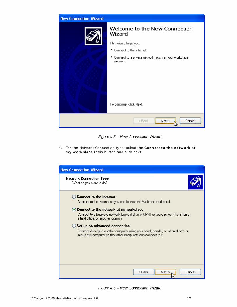
Figure 4.5 – New Connection Wizard
d. For the Network Connection type, select the Connect to the network at my workplace radio button and click next.
Figure 4.6 – New Connection Wizard
© Copyright 2005 Hewlett-Packard Company, LP. 12
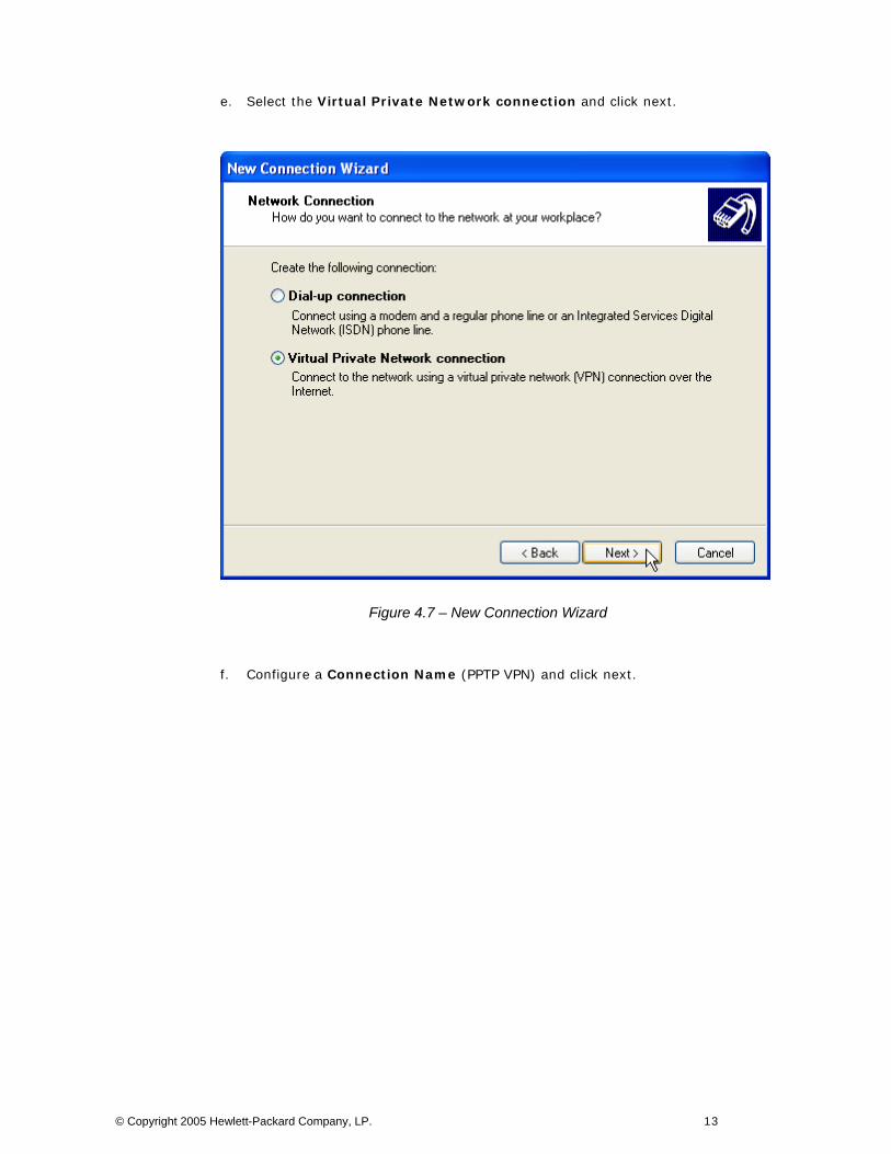
e. Select the Virtual Private Network connection and click next.
Figure 4.7 – New Connection Wizard
f. Configure a Connection Name (PPTP VPN) and click next.
© Copyright 2005 Hewlett-Packard Company, LP. 13
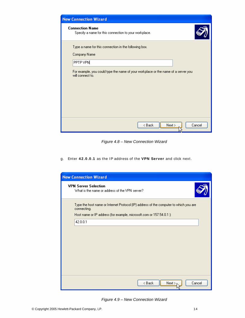
Figure 4.8 – New Connection Wizard
g. Enter 42.0.0.1 as the IP address of the VPN Server and click next.
Figure 4.9 – New Connection Wizard
© Copyright 2005 Hewlett-Packard Company, LP. 14
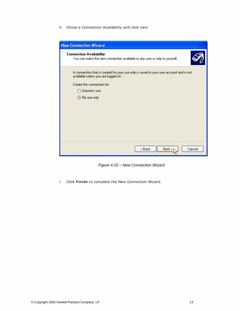
h. Chose a Connection Availability and click next.
Figure 4.10 – New Connection Wizard
i. Click Finish to complete the New Connection Wizard.
© Copyright 2005 Hewlett-Packard Company, LP. 15
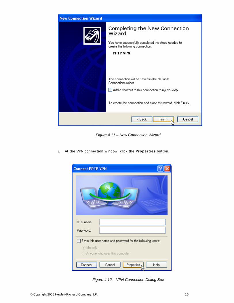
Figure 4.11 – New Connection Wizard
j. At the VPN connection window, click the Properties button.
Figure 4.12 – VPN Connection Dialog Box
© Copyright 2005 Hewlett-Packard Company, LP. 16
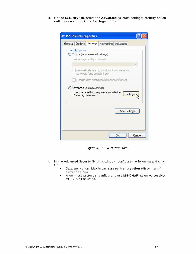
k. On the Security tab, select the Advanced (custom settings) security option radio button and click the Settings button.
Figure 4.13 – VPN Properties
l. In the Advanced Security Settings window, configure the following and click OK.
• Data encryption: Maximum strength encryption (disconnect if server declines)
• Allow these protocols: configure to use MS-CHAP v2 only; deselect MS-CHAP if selected.
© Copyright 2005 Hewlett-Packard Company, LP. 17
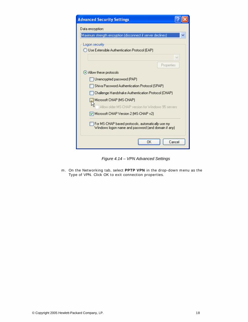
Figure 4.14 – VPN Advanced Settings
m. On the Networking tab, select PPTP VPN in the drop-down menu as the Type of VPN. Click OK to exit connection properties.
© Copyright 2005 Hewlett-Packard Company, LP. 18
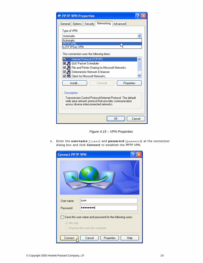
Figure 4.15 – VPN Properties
n. Enter the username (juser) and password (password) at the connection dialog box and click Connect to establish the PPTP VPN.
© Copyright 2005 Hewlett-Packard Company, LP. 19
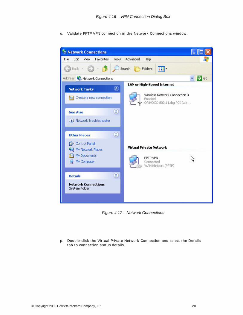
Figure 4.16 – VPN Connection Dialog Box
o. Validate PPTP VPN connection in the Network Connections window.
Figure 4.17 – Network Connections
p. Double-click the Virtual Private Network Connection and select the Details tab to connection status details.
© Copyright 2005 Hewlett-Packard Company, LP. 20
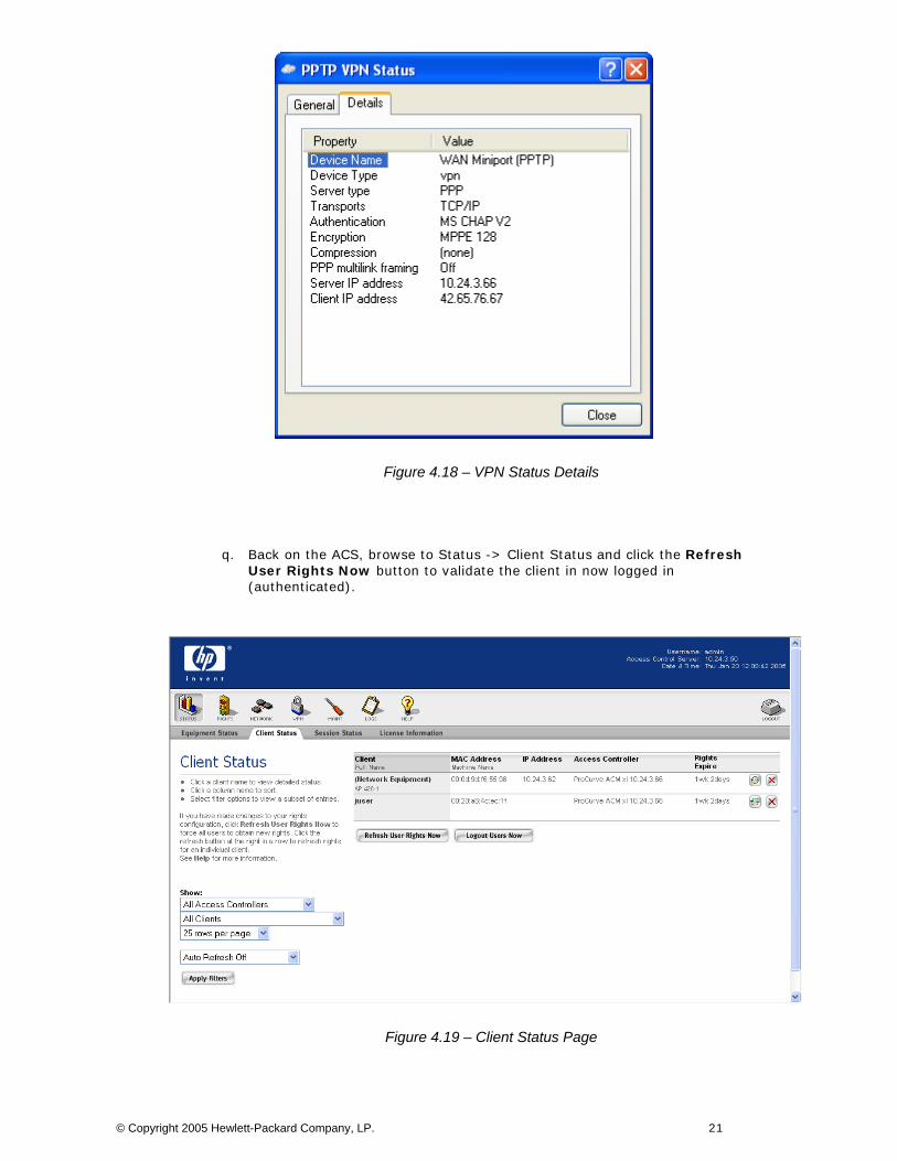
Figure 4.18 – VPN Status Details
q. Back on the ACS, browse to Status -> Client Status and click the Refresh User Rights Now button to validate the client in now logged in (authenticated).
Figure 4.19 – Client Status Page
© Copyright 2005 Hewlett-Packard Company, LP. 21
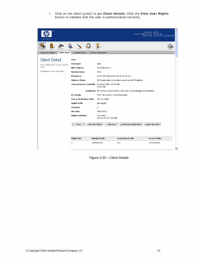
r. Click on the client (juser) to get Client details. Click the View User Rights button to validate that the user is authenticated correctly.
Figure 4.20 – Client Details
© Copyright 2005 Hewlett-Packard Company, LP. 22
Configuring Scenario 5: Wireless Data Privacy Logon using VPN Authentication (L2TP/IPSec) Scenario 5 consists of a wireless, Windows XP client authenticating via a VPN. The VPN used in this example will be an L2TP/IPSec VPN. Since VPN authentication requires a RADIUS backend, we will configure an ACS to authenticate VPN users against Internet Authentication Service (IAS), Microsoft’s RADIUS implementation. The steps required are:
• On the ACS, enable L2TP and IPSec VPN support globally. • On the ACS, configure Unauthenticated and Authenticated Access Policies for:
L2TP/IPSec VPN support Real IP addresses inside the encrypted VPN tunnel
• On the ACS, define a RADIUS Authentication Service and associate it to the System Authentication Policy.
• From the ACS, configure the ProCurve Access Control xl Module with the DHCP Server IP Address to allow clients to use Real IP addresses for the inner VPN tunnel.
• On the AP 420, configure open authentication wireless parameters. • On the wireless Windows XP client, configure the ProCurve VPN and Windows XP
VPN client software for L2TP/IPSec. • Connect and verify authentication.
1) On the ACS, enable L2TP and IPSec support globally.
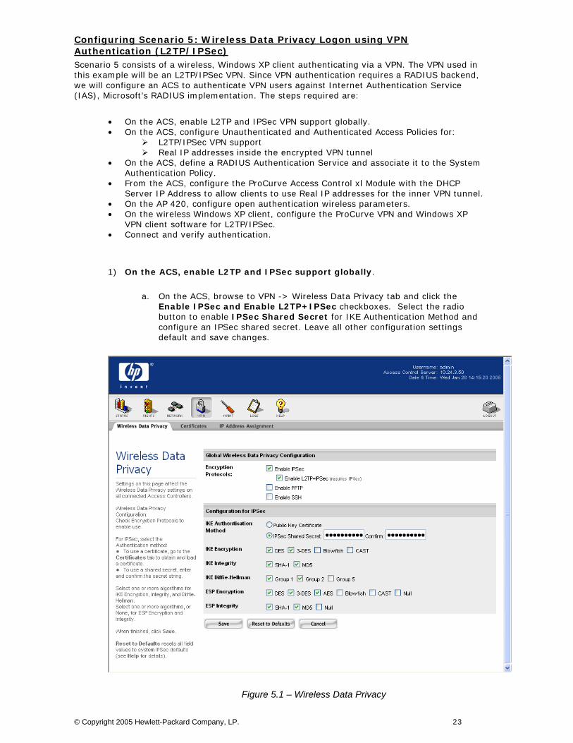
a. On the ACS, browse to VPN -> Wireless Data Privacy tab and click the Enable IPSec and Enable L2TP+IPSec checkboxes. Select the radio button to enable IPSec Shared Secret for IKE Authentication Method and configure an IPSec shared secret. Leave all other configuration settings default and save changes.
Figure 5.1 – Wireless Data Privacy
© Copyright 2005 Hewlett-Packard Company, LP. 23
2) On the ACS, enable L2TP/IPSec VPN support in both the Unauthenticated and Authenticated Access Policies.
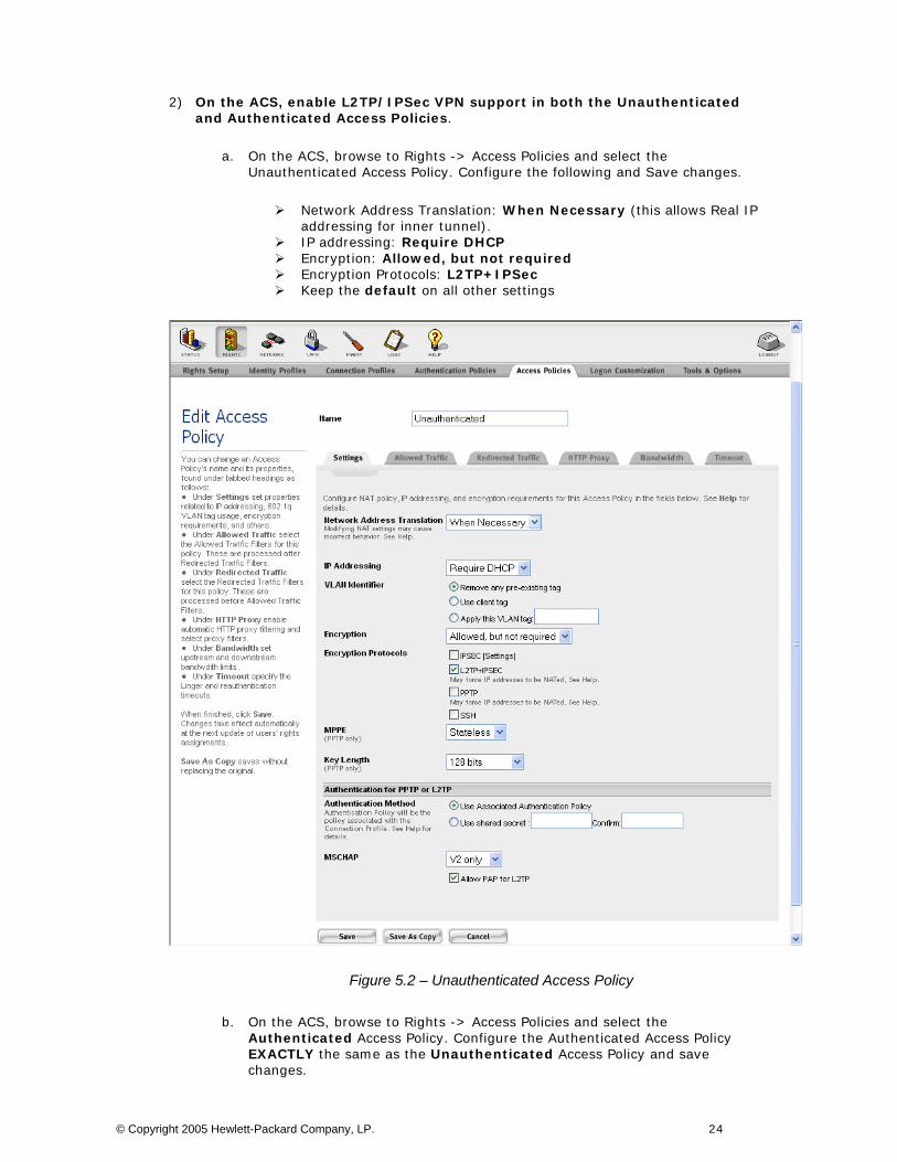
a. On the ACS, browse to Rights -> Access Policies and select the Unauthenticated Access Policy. Configure the following and Save changes.
Network Address Translation: When Necessary (this allows Real IP addressing for inner tunnel).
IP addressing: Require DHCP Encryption: Allowed, but not required Encryption Protocols: L2TP+IPSec Keep the default on all other settings
Figure 5.2 – Unauthenticated Access Policy
b. On the ACS, browse to Rights -> Access Policies and select the Authenticated Access Policy. Configure the Authenticated Access Policy EXACTLY the same as the Unauthenticated Access Policy and save changes.
© Copyright 2005 Hewlett-Packard Company, LP. 24
c. On the ACS, browse to Status -> Client Status and click Refresh User Rights Now.
3) On the ACS, define a RADIUS Authentication Service and associate it to the System Authentication Policy.
Note: This assumes that the RADIUS server is configured and ready to authenticate clients. See Scenario 3 for more details.
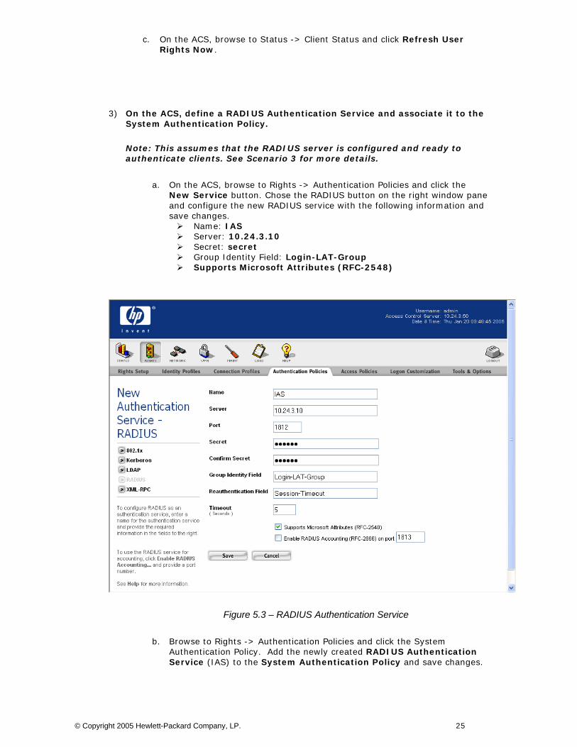
a. On the ACS, browse to Rights -> Authentication Policies and click the New Service button. Chose the RADIUS button on the right window pane and configure the new RADIUS service with the following information and save changes.
Name: IAS Server: 10.24.3.10 Secret: secret Group Identity Field: Login-LAT-Group Supports Microsoft Attributes (RFC-2548)
Figure 5.3 – RADIUS Authentication Service
b. Browse to Rights -> Authentication Policies and click the System Authentication Policy. Add the newly created RADIUS Authentication Service (IAS) to the System Authentication Policy and save changes.
© Copyright 2005 Hewlett-Packard Company, LP. 25
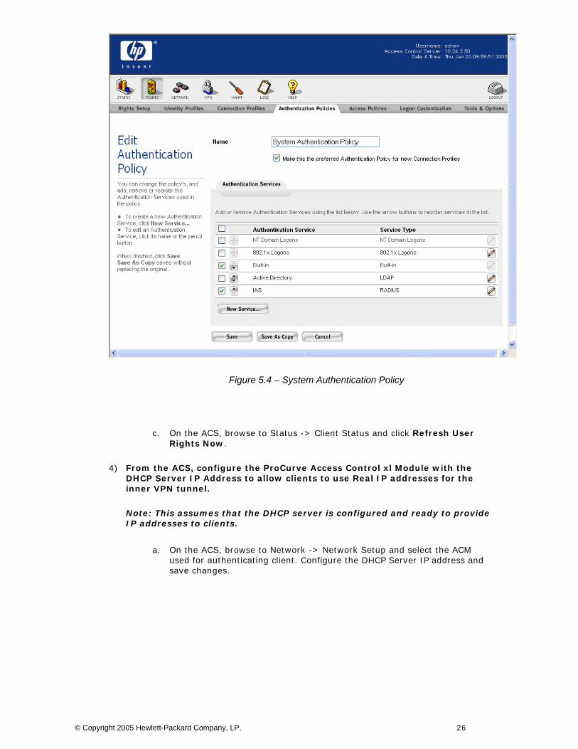
Figure 5.4 – System Authentication Policy
c. On the ACS, browse to Status -> Client Status and click Refresh User Rights Now.
4) From the ACS, configure the ProCurve Access Control xl Module with the DHCP Server IP Address to allow clients to use Real IP addresses for the inner VPN tunnel.
Note: This assumes that the DHCP server is configured and ready to provide IP addresses to clients.
a. On the ACS, browse to Network -> Network Setup and select the ACM used for authenticating client. Configure the DHCP Server IP address and save changes.
© Copyright 2005 Hewlett-Packard Company, LP. 26
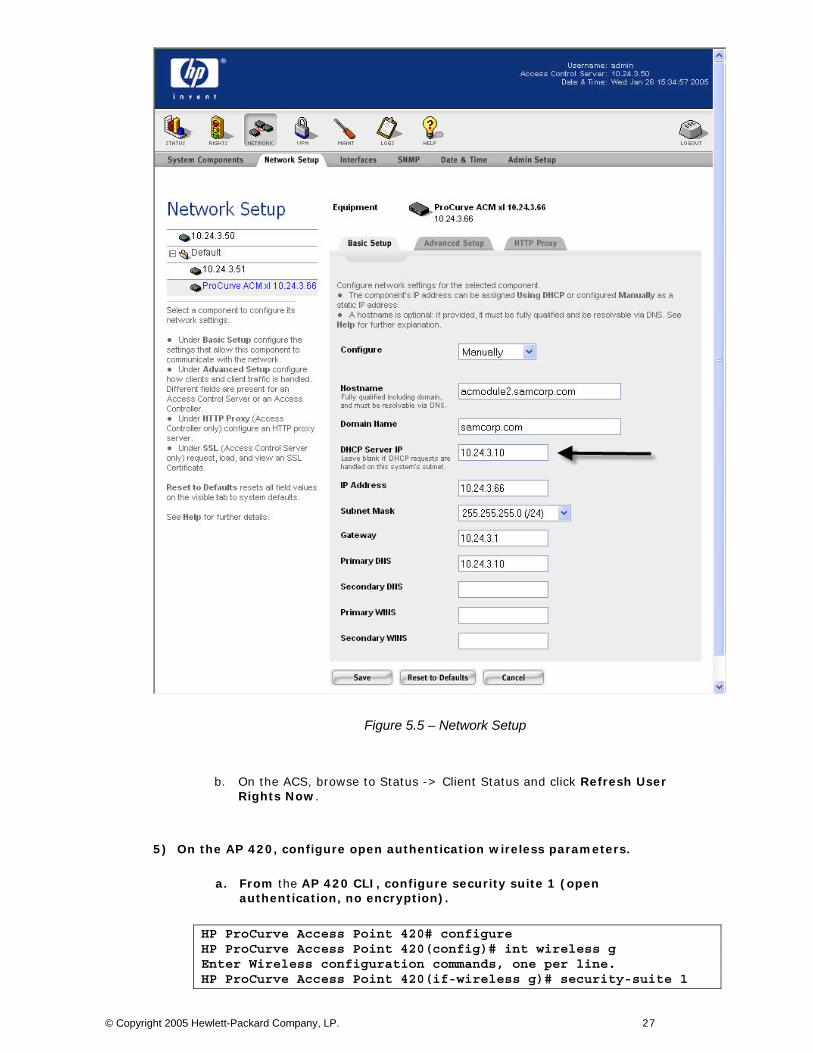
Figure 5.5 – Network Setup
b. On the ACS, browse to Status -> Client Status and click Refresh User Rights Now.
5) On the AP 420, configure open authentication wireless parameters.
a. From the AP 420 CLI, configure security suite 1 (open authentication, no encryption).
HP ProCurve Access Point 420# configure HP ProCurve Access Point 420(config)# int wireless g Enter Wireless configuration commands, one per line. HP ProCurve Access Point 420(if-wireless g)# security-suite 1
© Copyright 2005 Hewlett-Packard Company, LP. 27
6) On the wireless Windows XP client, configure the ProCurve VPN and Windows XP VPN client software for L2TP/IPSec.
Note: This assumes that the Access Point 420 is connected to the Access Control xl Module as “Network Equipment” and the client is associated.
Using L2TP/IPSec in this scenario is a three step process.
First, the ProCurve VPN client is installed and configured.
Second the Windows XP (native) VPN client software is configured.
Third, connect the L2TP/IPSec VPN using the Windows (native) VPN client.
This process automatically establishes the IPSec tunnel using the ProCurve VPN Client and uses the Windows (native) VPN client to establish the L2TP tunnel.
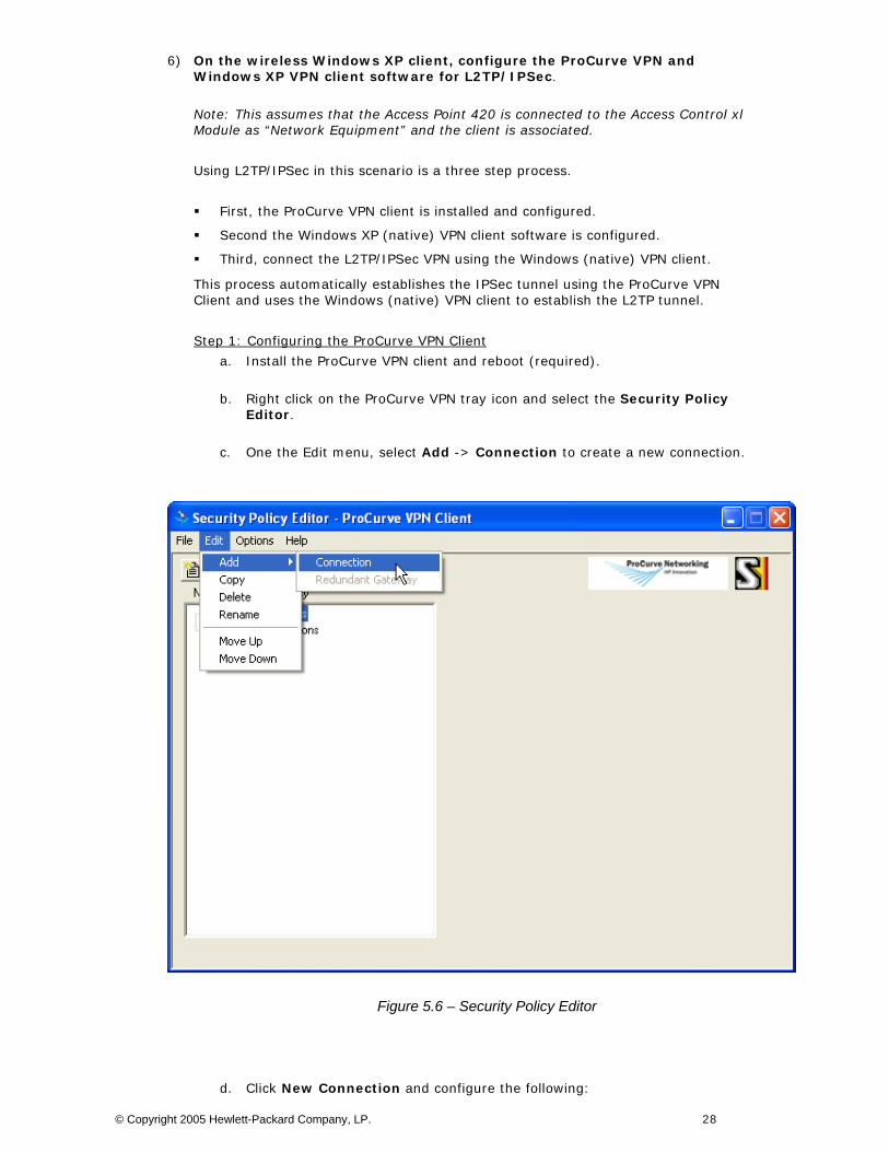
Step 1: Configuring the ProCurve VPN Client
a. Install the ProCurve VPN client and reboot (required).
b. Right click on the ProCurve VPN tray icon and select the Security Policy Editor.
c. One the Edit menu, select Add -> Connection to create a new connection.
Figure 5.6 – Security Policy Editor
d. Click New Connection and configure the following:
© Copyright 2005 Hewlett-Packard Company, LP. 28
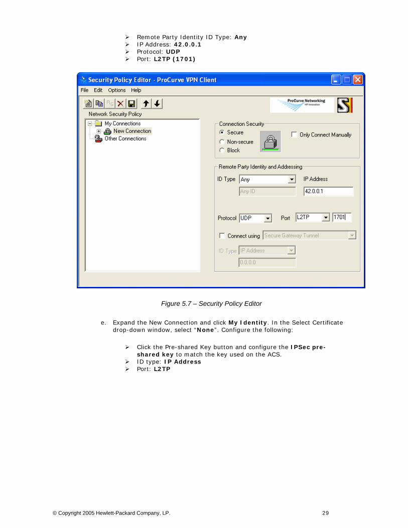
Remote Party Identity ID Type: Any IP Address: 42.0.0.1 Protocol: UDP Port: L2TP (1701)
Figure 5.7 – Security Policy Editor
e. Expand the New Connection and click My Identity. In the Select Certificate drop-down window, select “None”. Configure the following:
Click the Pre-shared Key button and configure the IPSec pre-shared key to match the key used on the ACS.
ID type: IP Address Port: L2TP
© Copyright 2005 Hewlett-Packard Company, LP. 29
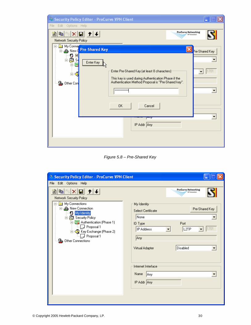
Figure 5.8 – Pre-Shared Key
© Copyright 2005 Hewlett-Packard Company, LP. 30
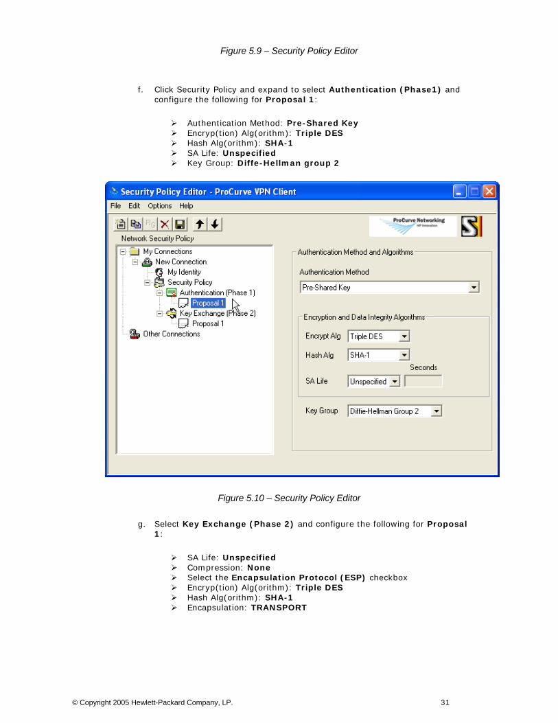
Figure 5.9 – Security Policy Editor
f. Click Security Policy and expand to select Authentication (Phase1) and configure the following for Proposal 1:
Authentication Method: Pre-Shared Key Encryp(tion) Alg(orithm): Triple DES Hash Alg(orithm): SHA-1 SA Life: Unspecified Key Group: Diffe-Hellman group 2
Figure 5.10 – Security Policy Editor
g. Select Key Exchange (Phase 2) and configure the following for Proposal 1:
SA Life: Unspecified Compression: None Select the Encapsulation Protocol (ESP) checkbox Encryp(tion) Alg(orithm): Triple DES Hash Alg(orithm): SHA-1 Encapsulation: TRANSPORT
© Copyright 2005 Hewlett-Packard Company, LP. 31
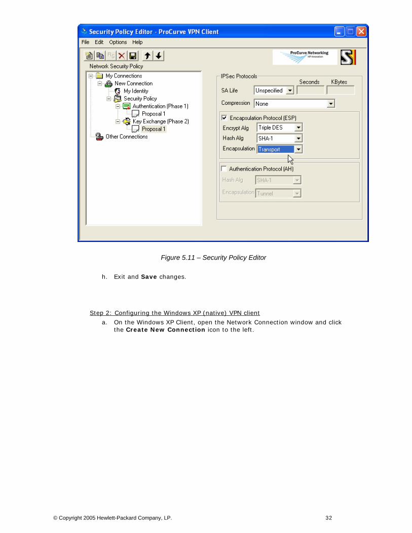
Figure 5.11 – Security Policy Editor
h. Exit and Save changes.
Step 2: Configuring the Windows XP (native) VPN client
a. On the Windows XP Client, open the Network Connection window and click the Create New Connection icon to the left.
© Copyright 2005 Hewlett-Packard Company, LP. 32
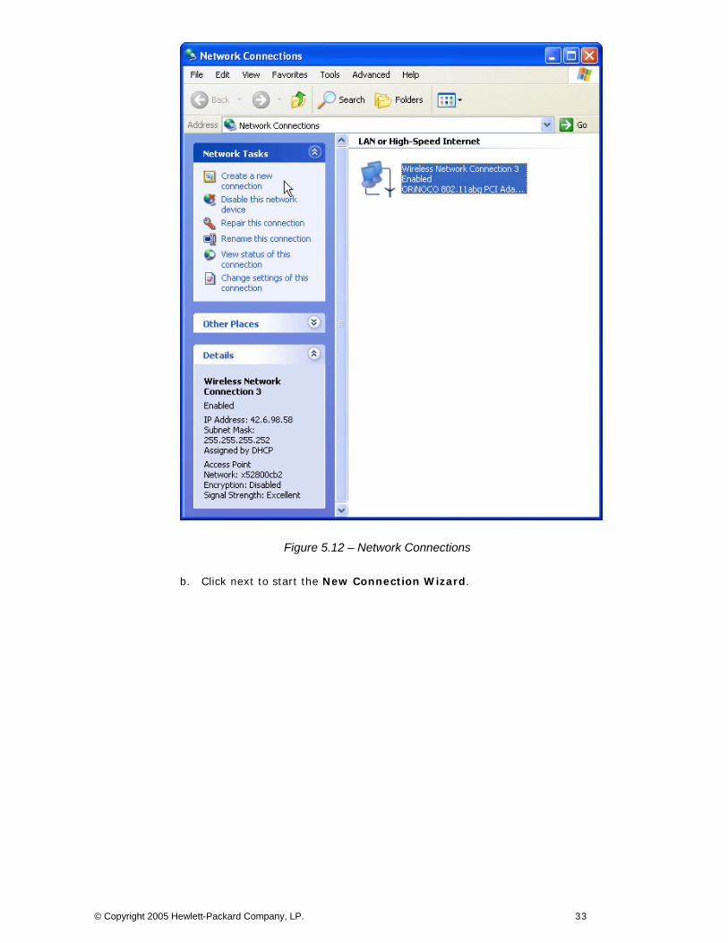
Figure 5.12 – Network Connections
b. Click next to start the New Connection Wizard.
© Copyright 2005 Hewlett-Packard Company, LP. 33
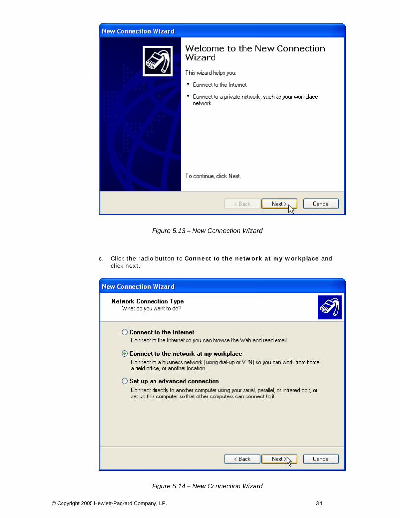
Figure 5.13 – New Connection Wizard
c. Click the radio button to Connect to the network at my workplace and click next.
Figure 5.14 – New Connection Wizard
© Copyright 2005 Hewlett-Packard Company, LP. 34
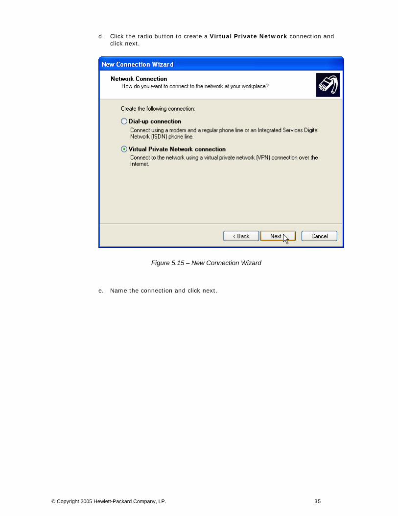
d. Click the radio button to create a Virtual Private Network connection and click next.
Figure 5.15 – New Connection Wizard
e. Name the connection and click next.
© Copyright 2005 Hewlett-Packard Company, LP. 35
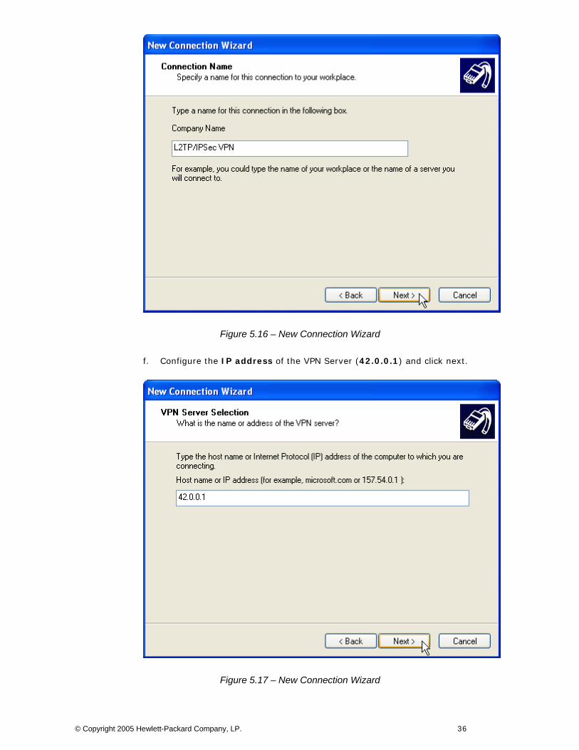
Figure 5.16 – New Connection Wizard
f. Configure the IP address of the VPN Server (42.0.0.1) and click next.
Figure 5.17 – New Connection Wizard
© Copyright 2005 Hewlett-Packard Company, LP. 36

g. Select a Connection Availability and click next. Click Finish to complete the New Connection Wizard.
Figure 5.18 – New Connection Wizard
h. At the VPN connection dialog box, click the Properties button.
Figure 5.19 – VPN Connection Dialog Box
© Copyright 2005 Hewlett-Packard Company, LP. 37
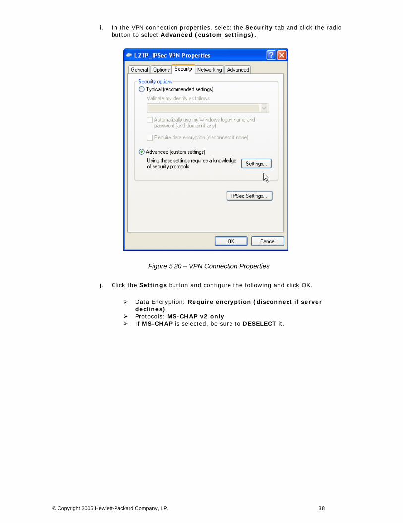
i. In the VPN connection properties, select the Security tab and click the radio button to select Advanced (custom settings).
Figure 5.20 – VPN Connection Properties
j. Click the Settings button and configure the following and click OK.
Data Encryption: Require encryption (disconnect if server declines)
Protocols: MS-CHAP v2 only If MS-CHAP is selected, be sure to DESELECT it.
© Copyright 2005 Hewlett-Packard Company, LP. 38

Figure 5.21 – Advanced Security Settings
k. Click the IPSec Settings button, configure the preshared key and click OK.
Figure 5.22 – IPSec Settings
l. On the Networking tab, configure the Type of VPN to L2TP IPSec VPN and click OK.
© Copyright 2005 Hewlett-Packard Company, LP. 39
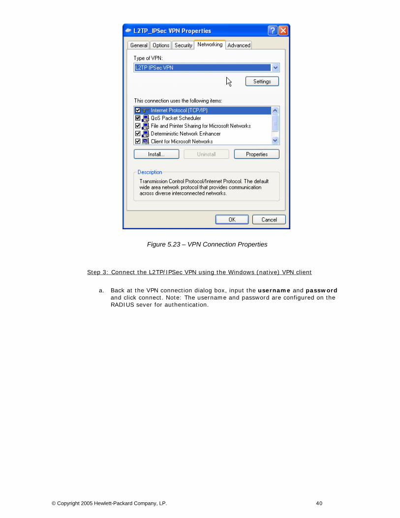
Figure 5.23 – VPN Connection Properties
Step 3: Connect the L2TP/IPSec VPN using the Windows (native) VPN client
a. Back at the VPN connection dialog box, input the username and password and click connect. Note: The username and password are configured on the RADIUS sever for authentication.
© Copyright 2005 Hewlett-Packard Company, LP. 40
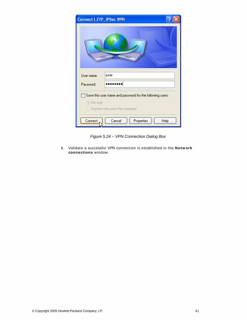
Figure 5.24 – VPN Connection Dialog Box
b. Validate a successful VPN connection is established in the Network connections window.
© Copyright 2005 Hewlett-Packard Company, LP. 41
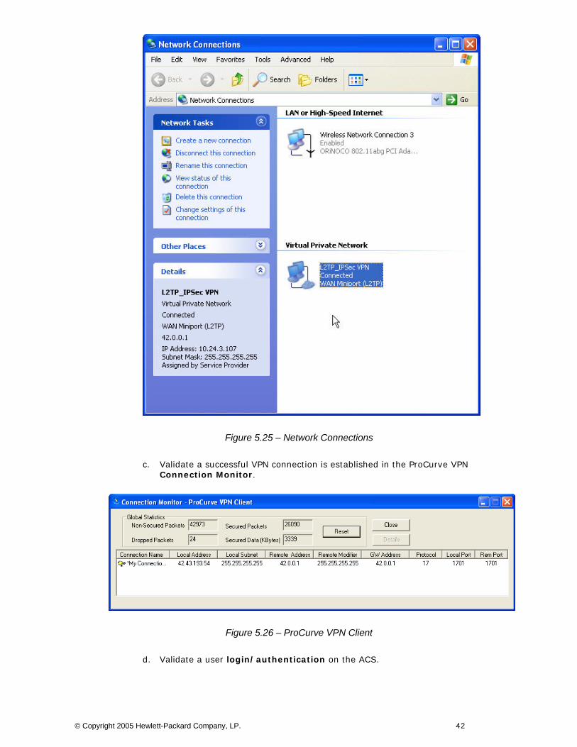
Figure 5.25 – Network Connections
c. Validate a successful VPN connection is established in the ProCurve VPN Connection Monitor.
Figure 5.26 – ProCurve VPN Client
d. Validate a user login/authentication on the ACS.
© Copyright 2005 Hewlett-Packard Company, LP. 42
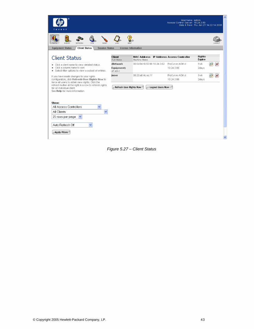
Figure 5.27 – Client Status
© Copyright 2005 Hewlett-Packard Company, LP. 43
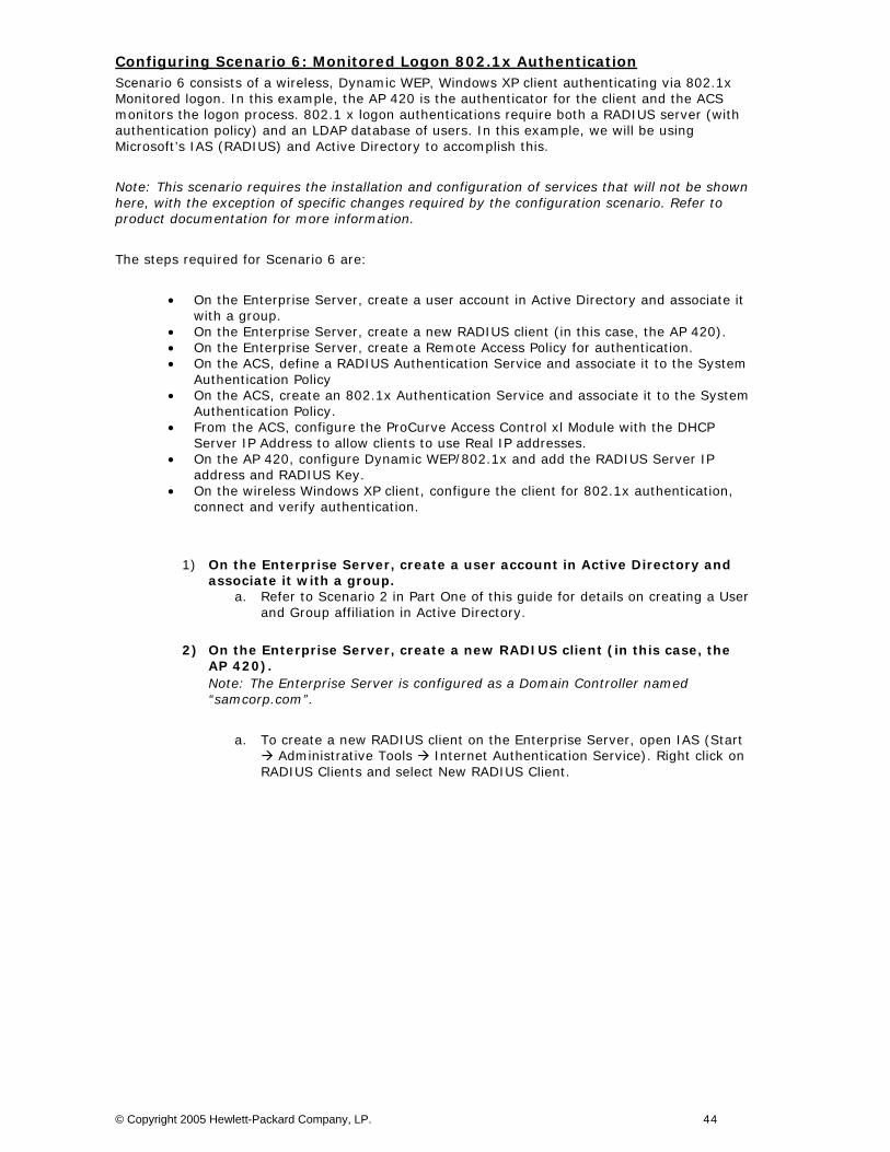
Configuring Scenario 6: Monitored Logon 802.1x Authentication Scenario 6 consists of a wireless, Dynamic WEP, Windows XP client authenticating via 802.1x Monitored logon. In this example, the AP 420 is the authenticator for the client and the ACS monitors the logon process. 802.1 x logon authentications require both a RADIUS server (with authentication policy) and an LDAP database of users. In this example, we will be using Microsoft’s IAS (RADIUS) and Active Directory to accomplish this.
Note: This scenario requires the installation and configuration of services that will not be shown here, with the exception of specific changes required by the configuration scenario. Refer to product documentation for more information.
The steps required for Scenario 6 are:
• On the Enterprise Server, create a user account in Active Directory and associate it with a group.
• On the Enterprise Server, create a new RADIUS client (in this case, the AP 420). • On the Enterprise Server, create a Remote Access Policy for authentication. • On the ACS, define a RADIUS Authentication Service and associate it to the System
Authentication Policy • On the ACS, create an 802.1x Authentication Service and associate it to the System
Authentication Policy. • From the ACS, configure the ProCurve Access Control xl Module with the DHCP
Server IP Address to allow clients to use Real IP addresses. • On the AP 420, configure Dynamic WEP/802.1x and add the RADIUS Server IP
address and RADIUS Key. • On the wireless Windows XP client, configure the client for 802.1x authentication,
connect and verify authentication.
1) On the Enterprise Server, create a user account in Active Directory and associate it with a group.
a. Refer to Scenario 2 in Part One of this guide for details on creating a User and Group affiliation in Active Directory.
2) On the Enterprise Server, create a new RADIUS client (in this case, the AP 420). Note: The Enterprise Server is configured as a Domain Controller named “samcorp.com”.
a. To create a new RADIUS client on the Enterprise Server, open IAS (Start Administrative Tools Internet Authentication Service). Right click on
RADIUS Clients and select New RADIUS Client.
© Copyright 2005 Hewlett-Packard Company, LP. 44
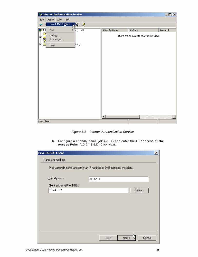
Figure 6.1 – Internet Authentication Service
b. Configure a Friendly name (AP 420-1) and enter the IP address of the Access Point (10.24.3.62). Click Next.
© Copyright 2005 Hewlett-Packard Company, LP. 45

Figure 6.2 – New RADIUS Client
c. Ensure RADIUS Standard is selected as the Client-Vendor and configure a shared secret (secret). Click Finish.
Figure 6.3 – New RADIUS Client
3) On the Enterprise Server, create a Remote Access Policy for authentication.
a. To create a Remote Access Policy on the Enterprise Server, open IAS (Start Administrative Tools Internet Authentication Service). Right click on Remote Access Policies and select New Remote Access Policy.
© Copyright 2005 Hewlett-Packard Company, LP. 46
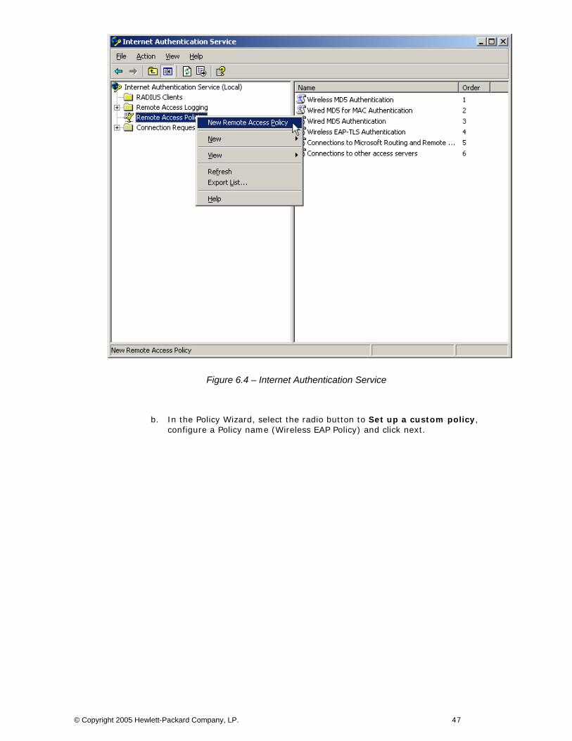
Figure 6.4 – Internet Authentication Service
b. In the Policy Wizard, select the radio button to Set up a custom policy, configure a Policy name (Wireless EAP Policy) and click next.
© Copyright 2005 Hewlett-Packard Company, LP. 47
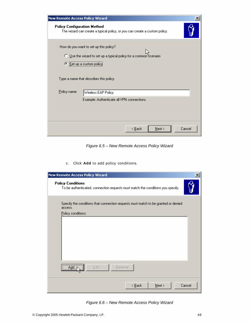
Figure 6.5 – New Remote Access Policy Wizard
c. Click Add to add policy conditions.
Figure 6.6 – New Remote Access Policy Wizard
© Copyright 2005 Hewlett-Packard Company, LP. 48
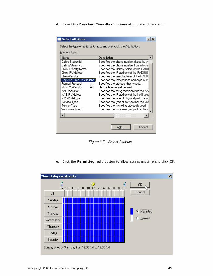
d. Select the Day-And-Time-Restrictions attribute and click add.
Figure 6.7 – Select Attribute
e. Click the Permitted radio button to allow access anytime and click OK.
© Copyright 2005 Hewlett-Packard Company, LP. 49
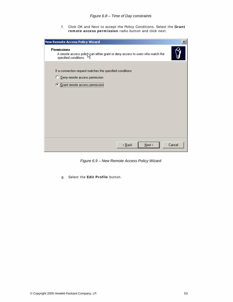
Figure 6.8 – Time of Day constraints
f. Click OK and Next to accept the Policy Conditions. Select the Grant remote access permission radio button and click next.
Figure 6.9 – New Remote Access Policy Wizard
g. Select the Edit Profile button.
© Copyright 2005 Hewlett-Packard Company, LP. 50
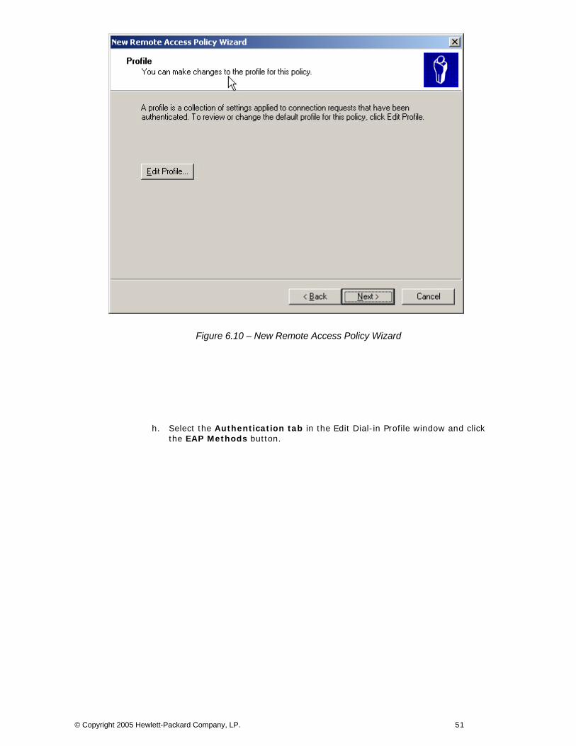
Figure 6.10 – New Remote Access Policy Wizard
h. Select the Authentication tab in the Edit Dial-in Profile window and click the EAP Methods button.
© Copyright 2005 Hewlett-Packard Company, LP. 51
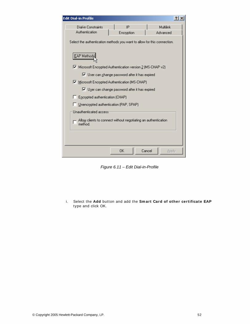
Figure 6.11 – Edit Dial-in-Profile
i. Select the Add button and add the Smart Card of other certificate EAP type and click OK.
© Copyright 2005 Hewlett-Packard Company, LP. 52

Figure 6.12 – Add EAP type
j. Click OK and Next to finish the New Remote Access Policy Wizard.
Figure 6.13 – New Remote Access Policy Wizard
© Copyright 2005 Hewlett-Packard Company, LP. 53
4) On the ACS, define a RADIUS Authentication Service and associate it to the System Authentication Policy.
a. Refer to Scenario 3 in Part One of this guide for details on defining a RADIUS Authentication Service and Associating is to the System Authentication Policy.
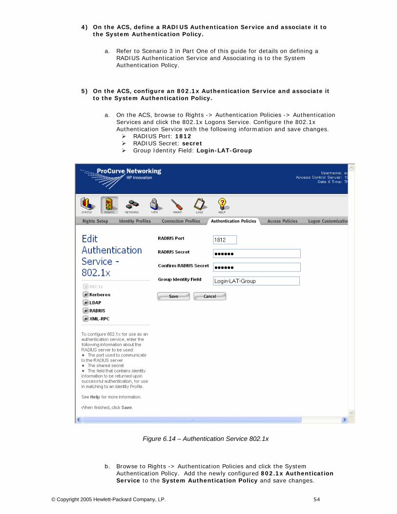
5) On the ACS, configure an 802.1x Authentication Service and associate it to the System Authentication Policy.
a. On the ACS, browse to Rights -> Authentication Policies -> Authentication Services and click the 802.1x Logons Service. Configure the 802.1x Authentication Service with the following information and save changes.
RADIUS Port: 1812 RADIUS Secret: secret Group Identity Field: Login-LAT-Group
Figure 6.14 – Authentication Service 802.1x
b. Browse to Rights -> Authentication Policies and click the System Authentication Policy. Add the newly configured 802.1x Authentication Service to the System Authentication Policy and save changes.
© Copyright 2005 Hewlett-Packard Company, LP. 54
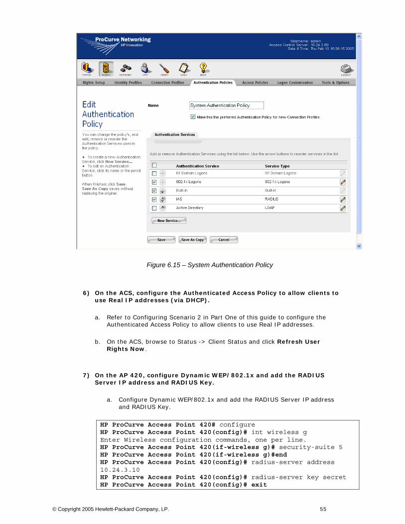
Figure 6.15 – System Authentication Policy
6) On the ACS, configure the Authenticated Access Policy to allow clients to use Real IP addresses (via DHCP).
a. Refer to Configuring Scenario 2 in Part One of this guide to configure the Authenticated Access Policy to allow clients to use Real IP addresses.
b. On the ACS, browse to Status -> Client Status and click Refresh User Rights Now.
7) On the AP 420, configure Dynamic WEP/802.1x and add the RADIUS Server IP address and RADIUS Key.
a. Configure Dynamic WEP/802.1x and add the RADIUS Server IP address and RADIUS Key.
HP ProCurve Access Point 420# configure HP ProCurve Access Point 420(config)# int wireless g Enter Wireless configuration commands, one per line. HP ProCurve Access Point 420(if-wireless g)# security-suite 5 HP ProCurve Access Point 420(if-wireless g)#end HP ProCurve Access Point 420(config)# radius-server address 10.24.3.10 HP ProCurve Access Point 420(config)# radius-server key secret HP ProCurve Access Point 420(config)# exit
© Copyright 2005 Hewlett-Packard Company, LP. 55
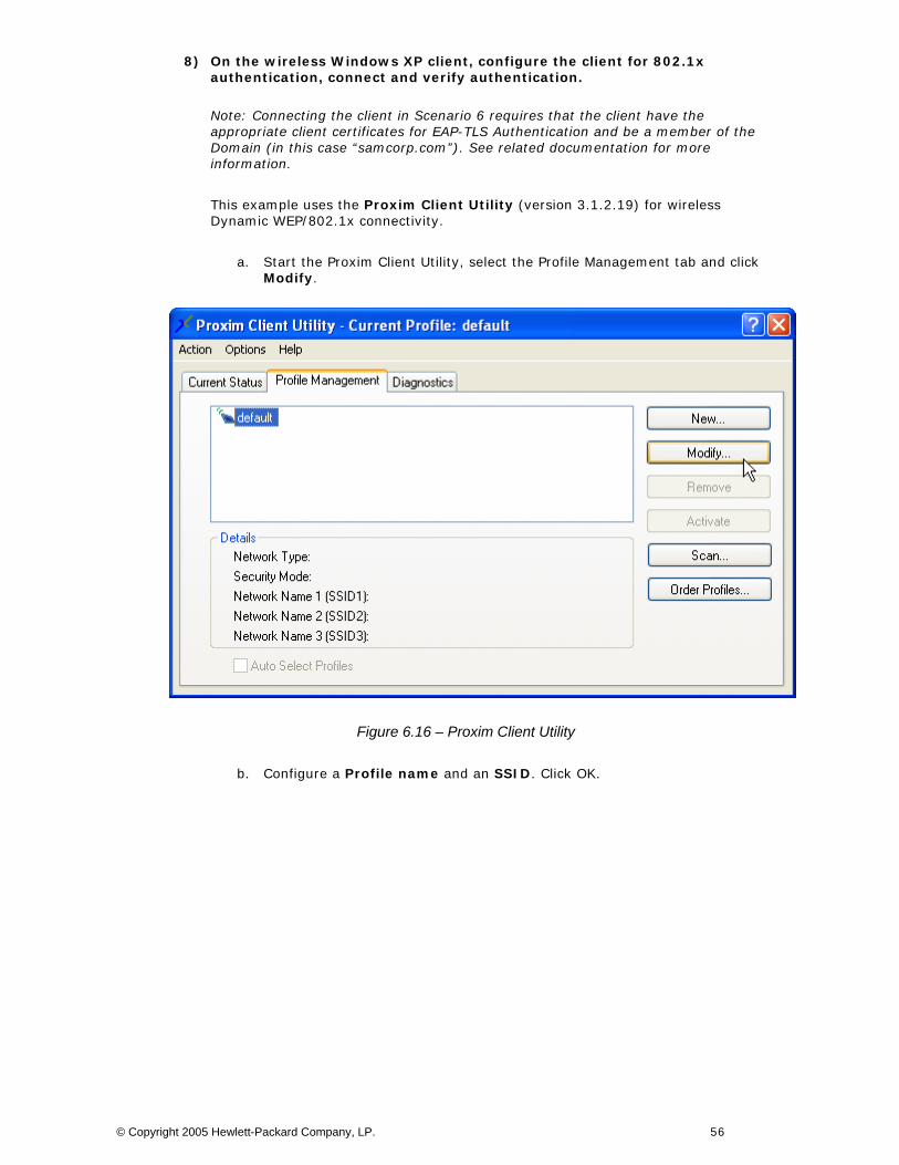
8) On the wireless Windows XP client, configure the client for 802.1x authentication, connect and verify authentication.
Note: Connecting the client in Scenario 6 requires that the client have the appropriate client certificates for EAP-TLS Authentication and be a member of the Domain (in this case “samcorp.com”). See related documentation for more information.
This example uses the Proxim Client Utility (version 3.1.2.19) for wireless Dynamic WEP/802.1x connectivity.
a. Start the Proxim Client Utility, select the Profile Management tab and click Modify.
Figure 6.16 – Proxim Client Utility
b. Configure a Profile name and an SSID. Click OK.
© Copyright 2005 Hewlett-Packard Company, LP. 56
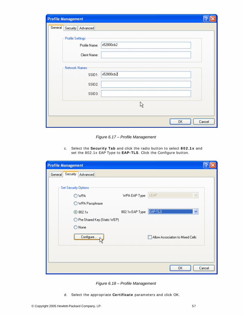
Figure 6.17 – Profile Management
c. Select the Security Tab and click the radio button to select 802.1x and set the 802.1x EAP Type to EAP-TLS. Click the Configure button.
Figure 6.18 – Profile Management
d. Select the appropriate Certificate parameters and click OK.
© Copyright 2005 Hewlett-Packard Company, LP. 57
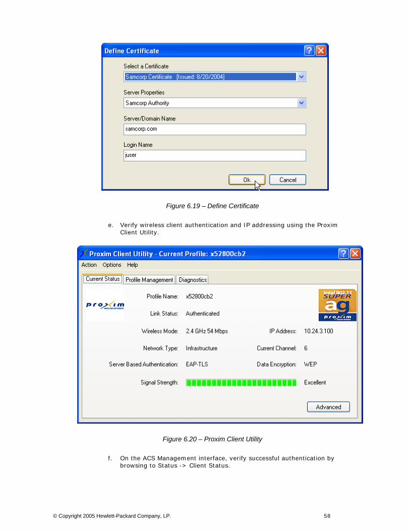
Figure 6.19 – Define Certificate
e. Verify wireless client authentication and IP addressing using the Proxim Client Utility.
Figure 6.20 – Proxim Client Utility
f. On the ACS Management interface, verify successful authentication by browsing to Status -> Client Status.
© Copyright 2005 Hewlett-Packard Company, LP. 58
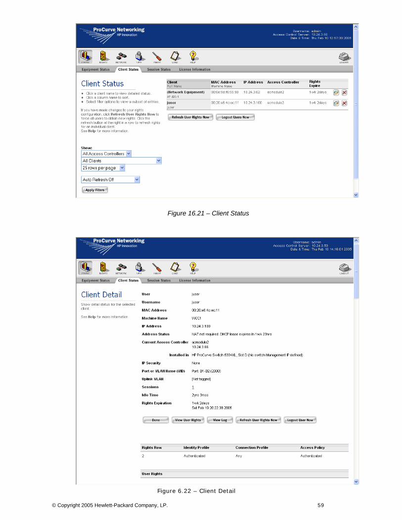
Figure 16.21 – Client Status
Figure 6.22 – Client Detail
© Copyright 2005 Hewlett-Packard Company, LP. 59

To find out more about ProCurve Networking products and solutions, visit our Web site at
www.procurve.com
©cpace
M
Copyright 2005 Hewlett-Packard Development Company, L.P. The information ontained herein is subject to change without notice. The only warranties for HP roducts and services are set forth in the express warranty statements ccompanying such products and services. Nothing herein should be construed as onstituting an additional warranty. HP shall not be liable for technical or editorial rrors or omissions contained herein.
arch 2005