Section/division Accident and Incident Investigation ... and Incidents Reports/9169.pdf ·...
61
CA 12-12a 25 MAY 2010 Page 1 of 61 Section/division Accident and Incident Investigation Division Form Number: CA 12-12a AIRCRAFT ACCIDENT REPORT AND EXECUTIVE SUMMARY Reference: CA18/2/3/9169 Aircraft Registration ZS-SAR Date of Accident 27 April 2013 Time of Accident ±1440Z Type of Aircraft Cessna 152 (Aeroplane) Type of Operation Private Flight Pilot-in-command Licence Type Private Age 40 Licence Valid Yes Pilot-in-command Flying Experience Total Flying Hours 173,0 Hours on Type 93,1 Last point of departure Worcester aerodrome (FAWC), Western Cape province Next point of intended landing Worcester aerodrome (FAWC), Western Cape province Location of the accident site with reference to easily defined geographical points (GPS readings if possible) Farm Wittekop in the Worcester district (GPS position; 33°42.507’ South 019°35.794’ East) Meteorological Information Surface wind; 260°/12kt gusting 23 kt, Temperature; 31°C, Visibility: + 10 km Number of people on board 1 + 0 No. of people injured 0 No. of people killed 1 Synopsis The aircraft, a Cessna 152 with registration number ZS-SAR, was hired by a member of the Worcester Flying Club for a local private flight. The pilot had indicated to the flying club members that he intended to fly for approximately one hour. The aircraft took off from runway 33 at Worcester aerodrome (FAWC) at approximately 1420Z. When the aircraft was overdue for landing by approximately one hour, the club members started getting concerned. They phoned the pilot on his cell phone, but without any response. They then started phoning farmers in the area as well as air traffic control (ATC) at Cape Town International aerodrome (FACT) to enquire whether the aircraft had been in radio communication with them, which was not the case. At around 1900Z that evening they received a call that the wreckage of the missing aircraft had been located on the farm Wittekop, which was located 9,2 nautical miles (nm) southeast of FAWC. The pilot was fatally injured in the accident. Probable cause The right-hand rudder cable was found to have failed. This most probably rendered the pilot without rudder authority to counteract the spin and recover from the manoeuvre. IARC Date Release Date
Transcript of Section/division Accident and Incident Investigation ... and Incidents Reports/9169.pdf ·...
CA 12-12a 25 MAY 2010 Page 1 of 61
Section/division Accident and Incident Investigation Division Form Number: CA 12-12a
AIRCRAFT ACCIDENT REPORT AND EXECUTIVE SUMMARY
Reference: CA18/2/3/9169
Aircraft Registration ZS-SAR Date of Accident 27 April 2013
Time of Accident ±1440Z
Type of Aircraft Cessna 152 (Aeroplane) Type of Operation Private Flight
Pilot-in-command Licence Type Private Age 40 Licence Valid Yes
Pilot-in-command Flying Experience
Total Flying Hours
173,0 Hours on Type 93,1
Last point of departure Worcester aerodrome (FAWC), Western Cape province
Next point of intended landing Worcester aerodrome (FAWC), Western Cape province
Location of the accident site with reference to easily defined geographical points (GPS readings if possible)
Farm Wittekop in the Worcester district (GPS position; 33°42.507’ South 019°35.794’ East)
Meteorological Information Surface wind; 260°/12kt gusting 23 kt, Temperature; 31°C, Visibility: + 10 km
Number of people on board 1 + 0 No. of people injured 0 No. of people killed 1
Synopsis
The aircraft, a Cessna 152 with registration number ZS-SAR, was hired by a member of the Worcester Flying Club for a local private flight. The pilot had indicated to the flying club members that he intended to fly for approximately one hour. The aircraft took off from runway 33 at Worcester aerodrome (FAWC) at approximately 1420Z. When the aircraft was overdue for landing by approximately one hour, the club members started getting concerned. They phoned the pilot on his cell phone, but without any response. They then started phoning farmers in the area as well as air traffic control (ATC) at Cape Town International aerodrome (FACT) to enquire whether the aircraft had been in radio communication with them, which was not the case. At around 1900Z that evening they received a call that the wreckage of the missing aircraft had been located on the farm Wittekop, which was located 9,2 nautical miles (nm) southeast of FAWC. The pilot was fatally injured in the accident.
Probable cause
The right-hand rudder cable was found to have failed. This most probably rendered the pilot without rudder authority to counteract the spin and recover from the manoeuvre.
IARC Date Release Date
CA 12-12a 25 MAY 2010 Page 2 of 61
Section/division Accident and Incident Investigation Division Form Number: CA 12-12a
AIRCRAFT ACCIDENT REPORT
Name of Owner : Worcester Flying Club
Name of Operator : Worcester Flying Club
Manufacturer : Cessna Aircraft Company
Model : 152
Nationality : South African
Registration Marks : ZS-SAR
Place : Farm Wittekop, Worcester district
Date : 27 April 2013
Time : ±1440Z
All times given in this report are Co-ordinated Universal Time (UTC) and will be denoted by (Z). South
African Standard Time is UTC plus 2 hours.
Purpose of the Investigation:
In terms of Regulation 12.03.1 of the Civil Aviation Regulations (1997) this report was compiled in the
interest of the promotion of aviation safety and the reduction of the risk of aviation accidents or incidents and
not to establish legal liability.
Disclaimer:
This report is produced without prejudice to the rights of the CAA, which are reserved.
1. FACTUAL INFORMATION 1.1 History of flight
1.1.1 The pilot, who was a member of the Worcester Flying Club, made a reservation with
the flying club to hire and fly a Cessna 152, registration ZS-SAR, on Saturday
afternoon, 27 April 2013. The pilot indicated that he planned to fly for approximately
one hour.
1.1.2 According to an official of the flying club the aircraft had been refuelled to capacity
the previous day, and following refuelling one flight had been conducted with the
aircraft with a total duration of 55 minutes (0,9 of an hour). The fuel that remained
in the aircraft prior to the flight was adequate for a 2½ hour flight. The pilot took off
from Worcester aerodrome (FAWC), runway 33 at approximately 1420Z. The
CA 12-12a 25 MAY 2010 Page 3 of 61
prevailing wind at the time was from the southwest at 7 knots, gusting up to 10
knots. At ±1440Z the wind speed increased to 12 knots, gusting up to 23 knots
from the southwest.
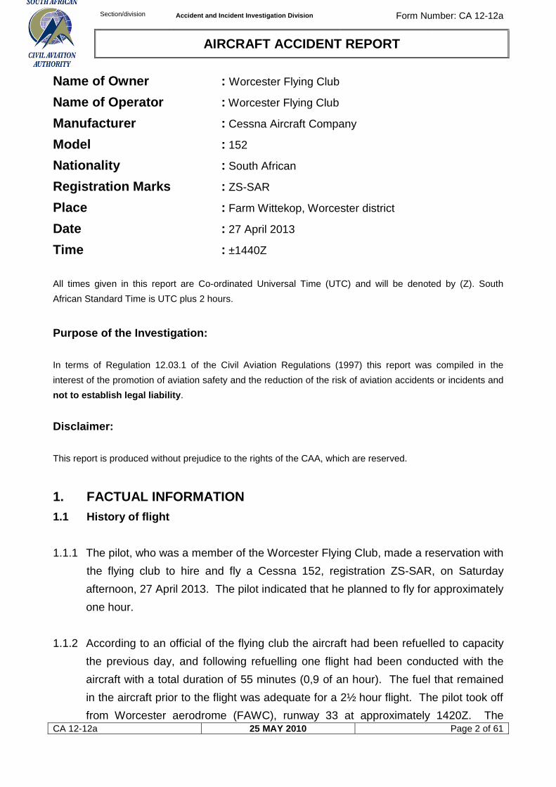
1.1.3 When the aircraft did not return to the aerodrome after being overdue for
approximately an hour, the club members started enquiring about the aircraft by
phoning the pilot’s cell number (without response) as well as people in the local
community (farmers). They also called air traffic control (ATC) at Cape Town
International aerodrome, as they thought the aircraft might have been in contact
with the tower, which was not the case. At around 1900Z that evening they
received a call that the wreckage of the missing aircraft had been located on the
farm Wittekop, which was located approximately 9,2 nautical miles (nm) southeast
of FAWC. The pilot was fatally injured in the accident.
Figure 1. The Google earth map indicates the accident site in relation to the Worcester aerodrome (FAWC)
1.1.4 The aircraft was observed flying in the vicinity of the farm Wittekop by a farm
worker on the afternoon of 27 April 2013. According to his observation the aircraft
was flying in the direction of Worcester (north-westerly). It then commenced with a
left turn, whereupon the attitude of the aircraft changed; it would appear to have
pitched nose up. The aircraft then fell to the ground in a nose-down attitude. The
farm worker immediately phoned the farm manager from his cell phone to notify him
of the accident, but the manager did not answer his phone immediately. He made
several attempts to call him without success. The farm manager phoned him back a
few hours later. After he had explained to him what had happened, the farm
manager drove to the farm, where he found the wreckage. He then informed the
FAWC
Accident site.
CA 12-12a 25 MAY 2010 Page 4 of 61
police and emergency services, which came to the accident scene. During an
interview with the eye-witness, the investigating team tried to establish the height
the aircraft was flying at when it commenced with the left-hand turn. It was,
however, not possible to make an accurate assessment of the height the aircraft
was at, but from what could be gathered the aircraft was most probably flying not
higher than 1000 feet above ground level (AGL).
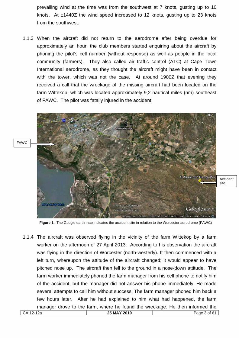
1.1.5 During the on-site investigation the team located the book “The Air Pilot’s Manual, 1
Flying Training”, by Trevor Thom, on the scene of the accident. The book had three
subheadings highlighted by page markers, namely forced landings, precautionary
landings and spins. The book was located on the right-hand side of the aircraft in
close proximity to the right-hand door, which was found in the open position
following ground impact.
Figure 2. The flying training handbook that was found on the accident site
1.1.6 The accident occurred during daylight conditions at a geographical position that was
determined to be 33° 42.507’ South 019° 35.794’ Ea st at an elevation of 1 052 feet
above mean sea level (AMSL).
CA 12-12a 25 MAY 2010 Page 5 of 61
1.2 Injuries to persons
Injuries Pilot Crew Pass. Other
Fatal 1 - - -
Serious - - - -
Minor - - - -
None - - - -
1.3 Damage to aircraft
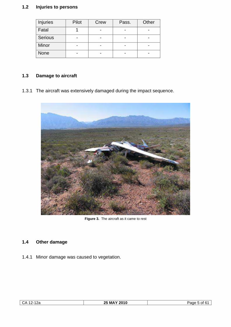
1.3.1 The aircraft was extensively damaged during the impact sequence.
Figure 3. The aircraft as it came to rest
1.4 Other damage
1.4.1 Minor damage was caused to vegetation.
CA 12-12a 25 MAY 2010 Page 6 of 61
1.5 Personnel Information
1.5.1 Pilot-in-command
Nationality South African Gender Male Age 40
Licence number 0270479157 Licence type Private pilot
Licence valid Yes Type endorsed Yes
Ratings None
Medical expiry date 31 December 2013
Restrictions None
Previous accidents None
The pilot commenced with his flying training as a student pilot on 18 December
1999. An application for a student pilot licence was received by the regulating
authority on 11 January 2000. On 13 February 2001 he submitted his application
for a private pilot licence; this was after he had passed his practical flight test on 5
February 2001, accumulating 54,9 flying hours during this period. The pilot
continued to keep his private pilot licence current. According to available evidence,
his last aviation medical examination prior to the accident flight was on 21
November 2011 and his last initial skills test (for private pilot licence - form CA 61-
03.4) on record was conducted on 16 May 2012. According to the pilot logbook,
which was kept up to date, he had flown a further nine flights following the
revalidation skills test flight on 16 May 2012 and had accumulated a further 8,3
flying hours over this period. His last flight prior to the accident flight was on 6 April
2013, during which he flew for 30 minutes (0,5 of an hour) on the Cessna 152, ZS-
SAR.
Flying experience:
Total hours 173,0
Total past 90-days 2,4
Total on type past 90 days 0,5
Total on type 93,1
CA 12-12a 25 MAY 2010 Page 7 of 61
1.6 Aircraft information
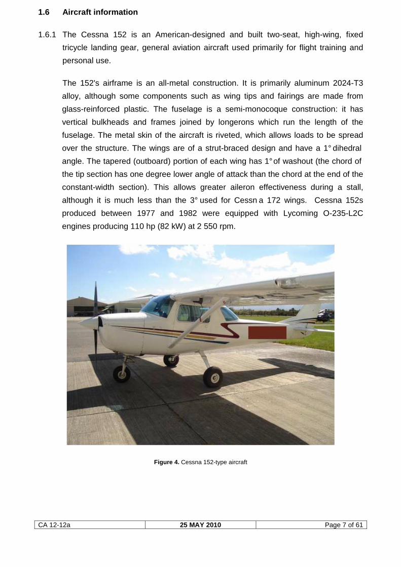
1.6.1 The Cessna 152 is an American-designed and built two-seat, high-wing, fixed
tricycle landing gear, general aviation aircraft used primarily for flight training and
personal use.
The 152's airframe is an all-metal construction. It is primarily aluminum 2024-T3
alloy, although some components such as wing tips and fairings are made from
glass-reinforced plastic. The fuselage is a semi-monocoque construction: it has
vertical bulkheads and frames joined by longerons which run the length of the
fuselage. The metal skin of the aircraft is riveted, which allows loads to be spread
over the structure. The wings are of a strut-braced design and have a 1° dihedral
angle. The tapered (outboard) portion of each wing has 1° of washout (the chord of
the tip section has one degree lower angle of attack than the chord at the end of the
constant-width section). This allows greater aileron effectiveness during a stall,
although it is much less than the 3° used for Cessn a 172 wings. Cessna 152s
produced between 1977 and 1982 were equipped with Lycoming O-235-L2C
engines producing 110 hp (82 kW) at 2 550 rpm.
Figure 4. Cessna 152-type aircraft
CA 12-12a 25 MAY 2010 Page 8 of 61
Airframe:
Type Cessna 152
Serial number 152-82591
Manufacturer Cessna Aircraft Company
Year of manufacture 1979
Total airframe hours (at time of accident) 11 086,1
Last MPI (hours & date) 11 000,0 16 November 2012
Hours since last MPI 86,1
C of A (issue date) 29 April 2008
C of A (expiry date) 28 April 2013
C of R (issue date) (present owner) 30 July 2008
Operating category Standard part 135
According to available documentation, read in conjunction with the tachometer
reading at the time of the accident, the aircraft was airborne for approximately 15
minutes.
Engine:
Type Lycoming O-235-L2C
Serial number L-22456-15
Hours since new 11 086,1
Hours since overhaul 1 386,1
Propeller:
Type McCauley 1A103/TCM6958
Serial number SR 773762
Hours since new 11 086,1
Hours since overhaul 186,1
1.6.2 Weight and balance
Approximately 52 litres of Avgas was drained from the aircraft fuel tanks at the
accident site prior to recovery of the wreckage. Both fuel tanks remained intact
during the impact sequence, although the left fuel tank became dislodged from its
upper wing attachments. The aircraft was equipped with an “ON” and “OFF” fuel
selector, which when in the “ON” position supplies fuel to the engine from both left
and right tanks simultaneously under gravity.
CA 12-12a 25 MAY 2010 Page 9 of 61
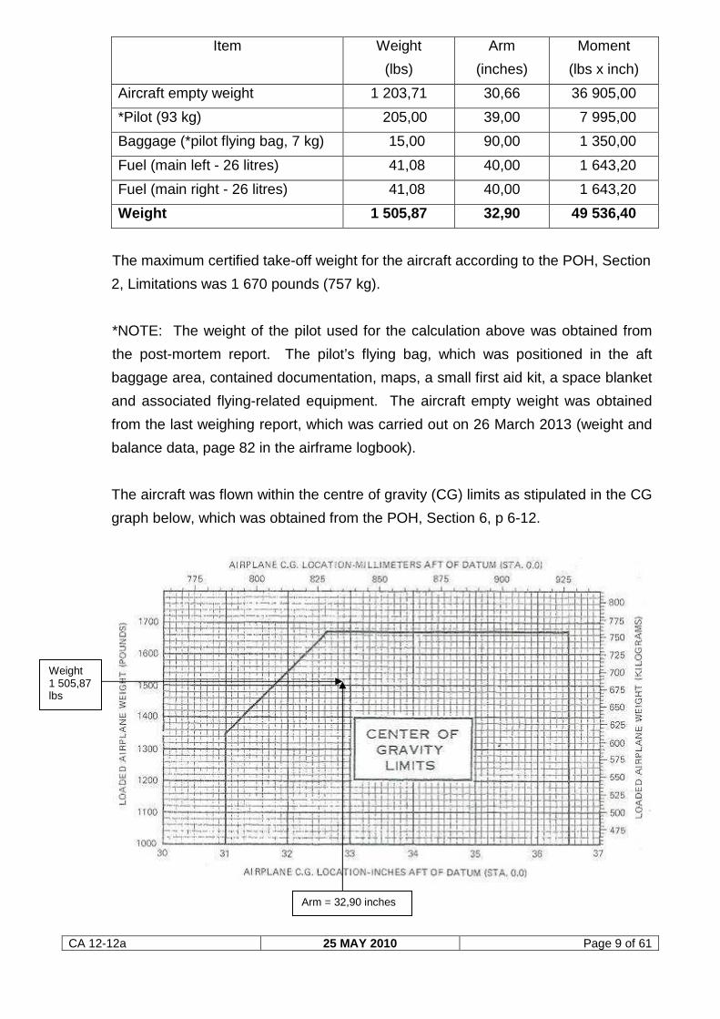
Item Weight
(lbs)
Arm
(inches)
Moment
(lbs x inch)
Aircraft empty weight 1 203,71 30,66 36 905,00
*Pilot (93 kg) 205,00 39,00 7 995,00
Baggage (*pilot flying bag, 7 kg) 15,00 90,00 1 350,00
Fuel (main left - 26 litres) 41,08 40,00 1 643,20
Fuel (main right - 26 litres) 41,08 40,00 1 643,20
Weight 1 505,87 32,90 49 536,40
The maximum certified take-off weight for the aircraft according to the POH, Section
2, Limitations was 1 670 pounds (757 kg).
*NOTE: The weight of the pilot used for the calculation above was obtained from
the post-mortem report. The pilot’s flying bag, which was positioned in the aft
baggage area, contained documentation, maps, a small first aid kit, a space blanket
and associated flying-related equipment. The aircraft empty weight was obtained
from the last weighing report, which was carried out on 26 March 2013 (weight and
balance data, page 82 in the airframe logbook).
The aircraft was flown within the centre of gravity (CG) limits as stipulated in the CG
graph below, which was obtained from the POH, Section 6, p 6-12.
Arm = 32,90 inches
Weight 1 505,87 lbs
CA 12-12a 25 MAY 2010 Page 10 of 61
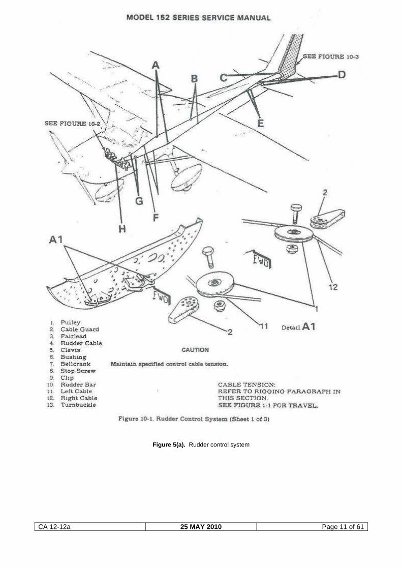
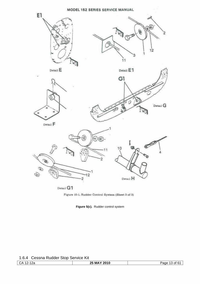
1.6.3 Rudder Control System
Source: Cessna 152 Service Manual
Description: “Rudder control is maintained through use of conventional rudder
pedals which also control nose wheel steering. The system is comprised of the
rudder pedals, cables and pulley, all of which link the pedals to the rudder and nose
wheel steering.”
The illustration on the next page, figure 5(a), provides the reader with some insight
into the layout of the rudder control system on the Cessna 152 type aircraft.
CA 12-12a 25 MAY 2010 Page 11 of 61
Figure 5(a). Rudder control system
CA 12-12a 25 MAY 2010 Page 12 of 61
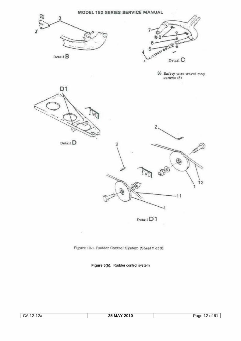
Figure 5(b). Rudder control system
CA 12-12a 25 MAY 2010 Page 13 of 61
Figure 5(c). Rudder control system
1.6.4 Cessna Rudder Stop Service Kit
CA 12-12a 25 MAY 2010 Page 14 of 61
According to the airframe logbook, page 85, the Cessna rudder stop service kit with
reference SEB01-1 was installed on the aircraft by an aircraft maintenance
organisation (AMO) in South Africa on 10 March 2008.
1.6.5 The Cessna Aircraft Company Model 152 Service Manual
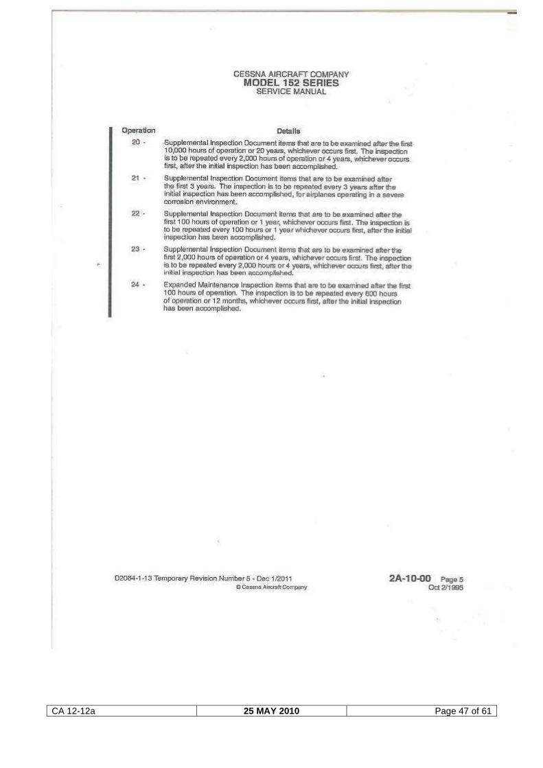
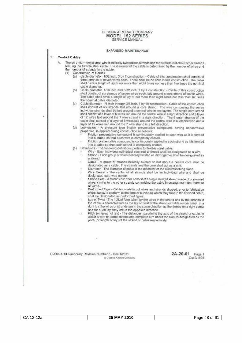
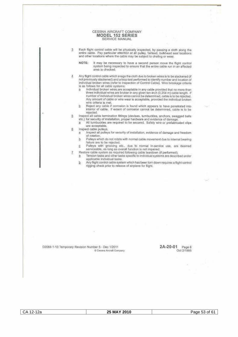
The service manual states that the rudder cables (Expanded Maintenance
Inspection) “Are to be examined after the first 100 hours of operation. The
inspection to be repeated every 600 hours of operation or 12 months, whichever
occurs first, after the initial inspection has been accomplished”.
“Rudder. 1. Check rudder travel and cable tension. 2. Check rudder cable system,
control cables and pulleys, in accordance with the flight cable inspection procedures
in Section 2A-20-01, Expanded Maintenance, Control Cables.”
The rudder inspection service manual requirement as well as the cable inspection
procedure as contained in Section 2A-20-01 can be found attached to this report as
Annexure B.
1.6.6 Aircraft maintenance inspections
The aircraft was imported into South Africa in early 2008. According to the airframe
logbook the aircraft was subjected to fourteen mandatory periodic inspections
(MPIs) since it was registered on the South African register, which amounted to
1 300 airframe hours. The last maintenance inspection that was carried out on the
aircraft prior to the accident flight was certified on 16 November 2012. The
supporting documentation with reference to the maintenance inspection was
obtained from the AMO. Under both subheadings ‘Airframe’ and ‘Control systems’
(Document: Cessna 152 Service Manual, Revision 1, dated 2 October 1995) the
relevant tasks with reference to cables were signed off.
The table on the next page presents a summary of the fourteen MPI inspections
certified on the aircraft.
Date of inspection Airframe hours Maintenance facility
10 March 2008 9 700.0 Approved AMO
CA 12-12a 25 MAY 2010 Page 15 of 61
13 November 2008 9 800.0 Approved AMO
11 February 2009 9 900.0 Approved AMO
15 April 2009 10 000.0 Approved AMO
5 July 2009 10 100.0 Approved AMO
24 September 2009 10 200.0 Approved AMO
1 April 2010 10 300.0 Approved AMO
12 August 2010 10 400.0 Approved AMO
7 December 2010 10 500.0 Approved AMO
28 January 2011 10 600.0 Approved AMO
2 June 2011 10 700.0 Approved AMO
25 October 2011 10 800.0 Approved AMO
18 May 2012 10 900.0 Approved AMO
16 November 2012 11 000.0 Approved AMO
1.6.7 Rudder cable inspection interval requirements
The rudder cables on these aircraft are ‘on condition’ items, which means they have
no defined service life prescribed by the aircraft manufacturer and are replaced
following assessment of the condition of the cables during maintenance inspections.
The inspections on these cables need to be conducted every 600 hours or 12
months, whichever occurs first. That would mean the cables are to be inspected
every 6th 100-hour periodic inspection, or once every 12 months if the aircraft hours
do not add up to 600 hours during a 12-month period. According to the
maintenance inspection table in paragraph 1.6.6, the cables were required to be
inspected once every 12 months, as the aircraft flying hours never added up to the
600 hours within a 12 month period. The 12-month items are usually inspected at a
mandatory periodic inspection closer to the 12-month date. (Inspection interval
requirements as per Cessna Service Manual are contained in Annexure B attached
to this report, subheading 24).
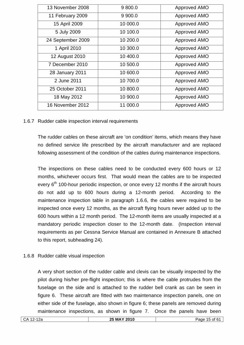
1.6.8 Rudder cable visual inspection
A very short section of the rudder cable and clevis can be visually inspected by the
pilot during his/her pre-flight inspection; this is where the cable protrudes from the
fuselage on the side and is attached to the rudder bell crank as can be seen in
figure 6. These aircraft are fitted with two maintenance inspection panels, one on
either side of the fuselage, also shown in figure 6; these panels are removed during
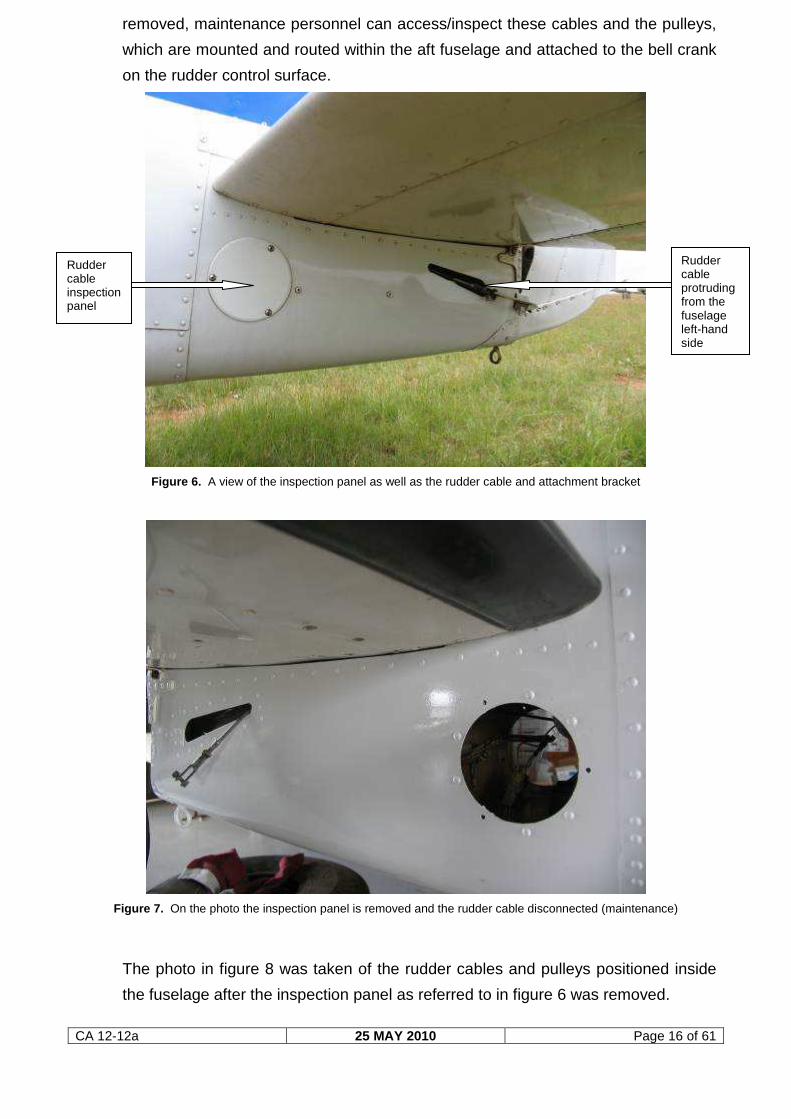
maintenance inspections, as shown in figure 7. Once the panels have been
CA 12-12a 25 MAY 2010 Page 16 of 61
removed, maintenance personnel can access/inspect these cables and the pulleys,
which are mounted and routed within the aft fuselage and attached to the bell crank
on the rudder control surface.
Figure 6. A view of the inspection panel as well as the rudder cable and attachment bracket
Figure 7. On the photo the inspection panel is removed and the rudder cable disconnected (maintenance)
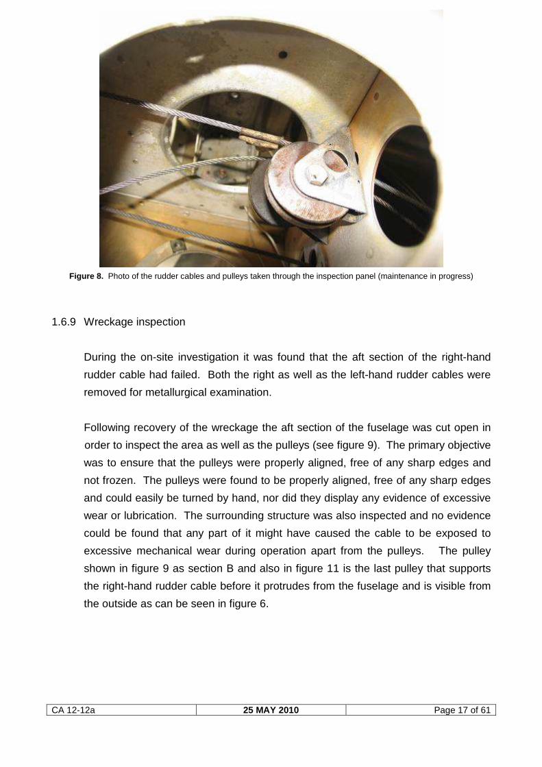
The photo in figure 8 was taken of the rudder cables and pulleys positioned inside
the fuselage after the inspection panel as referred to in figure 6 was removed.
Rudder cable inspection panel
Rudder cable protruding from the fuselage left-hand side
CA 12-12a 25 MAY 2010 Page 17 of 61
Figure 8. Photo of the rudder cables and pulleys taken through the inspection panel (maintenance in progress)
1.6.9 Wreckage inspection
During the on-site investigation it was found that the aft section of the right-hand
rudder cable had failed. Both the right as well as the left-hand rudder cables were
removed for metallurgical examination.
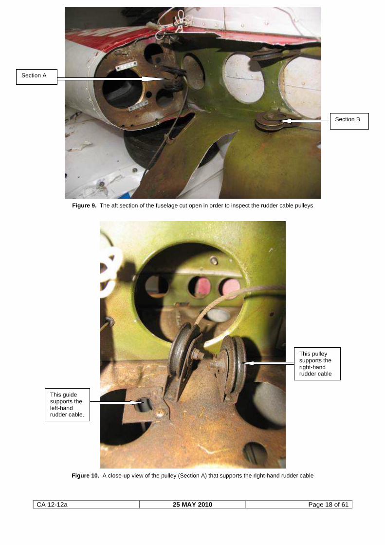
Following recovery of the wreckage the aft section of the fuselage was cut open in
order to inspect the area as well as the pulleys (see figure 9). The primary objective
was to ensure that the pulleys were properly aligned, free of any sharp edges and
not frozen. The pulleys were found to be properly aligned, free of any sharp edges
and could easily be turned by hand, nor did they display any evidence of excessive
wear or lubrication. The surrounding structure was also inspected and no evidence
could be found that any part of it might have caused the cable to be exposed to
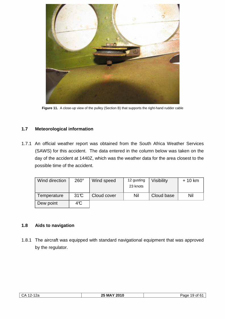
excessive mechanical wear during operation apart from the pulleys. The pulley
shown in figure 9 as section B and also in figure 11 is the last pulley that supports
the right-hand rudder cable before it protrudes from the fuselage and is visible from
the outside as can be seen in figure 6.
CA 12-12a 25 MAY 2010 Page 18 of 61
Figure 9. The aft section of the fuselage cut open in order to inspect the rudder cable pulleys
Figure 10. A close-up view of the pulley (Section A) that supports the right-hand rudder cable
Section A
Section B
This pulley supports the right-hand rudder cable
This guide supports the left-hand rudder cable.
CA 12-12a 25 MAY 2010 Page 19 of 61
Figure 11. A close-up view of the pulley (Section B) that supports the right-hand rudder cable
1.7 Meteorological information
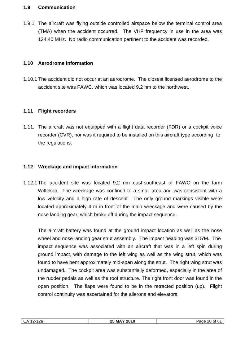
1.7.1 An official weather report was obtained from the South Africa Weather Services
(SAWS) for this accident. The data entered in the column below was taken on the
day of the accident at 1440Z, which was the weather data for the area closest to the
possible time of the accident.
Wind direction 260° Wind speed 12 gusting
23 knots
Visibility + 10 km
Temperature 31°C Cloud cover Nil Cloud base Nil
Dew point 4°C
1.8 Aids to navigation
1.8.1 The aircraft was equipped with standard navigational equipment that was approved
by the regulator.
CA 12-12a 25 MAY 2010 Page 20 of 61
1.9 Communication
1.9.1 The aircraft was flying outside controlled airspace below the terminal control area
(TMA) when the accident occurred. The VHF frequency in use in the area was
124.40 MHz. No radio communication pertinent to the accident was recorded.
1.10 Aerodrome information
1.10.1 The accident did not occur at an aerodrome. The closest licensed aerodrome to the
accident site was FAWC, which was located 9,2 nm to the northwest.
1.11 Flight recorders
1.11. The aircraft was not equipped with a flight data recorder (FDR) or a cockpit voice
recorder (CVR), nor was it required to be installed on this aircraft type according to
the regulations.
1.12 Wreckage and impact information
1.12.1 The accident site was located 9,2 nm east-southeast of FAWC on the farm
Wittekop. The wreckage was confined to a small area and was consistent with a
low velocity and a high rate of descent. The only ground markings visible were
located approximately 4 m in front of the main wreckage and were caused by the
nose landing gear, which broke off during the impact sequence.
The aircraft battery was found at the ground impact location as well as the nose
wheel and nose landing gear strut assembly. The impact heading was 315°M. The
impact sequence was associated with an aircraft that was in a left spin during
ground impact, with damage to the left wing as well as the wing strut, which was
found to have bent approximately mid-span along the strut. The right wing strut was
undamaged. The cockpit area was substantially deformed, especially in the area of
the rudder pedals as well as the roof structure. The right front door was found in the
open position. The flaps were found to be in the retracted position (up). Flight
control continuity was ascertained for the ailerons and elevators.
CA 12-12a 25 MAY 2010 Page 21 of 61
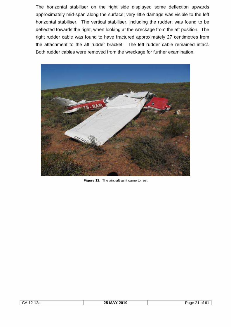
The horizontal stabiliser on the right side displayed some deflection upwards
approximately mid-span along the surface; very little damage was visible to the left
horizontal stabiliser. The vertical stabiliser, including the rudder, was found to be
deflected towards the right, when looking at the wreckage from the aft position. The
right rudder cable was found to have fractured approximately 27 centimetres from
the attachment to the aft rudder bracket. The left rudder cable remained intact.
Both rudder cables were removed from the wreckage for further examination.
Figure 12. The aircraft as it came to rest
CA 12-12a 25 MAY 2010 Page 22 of 61
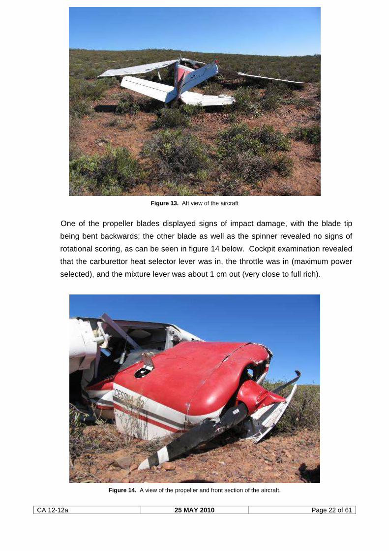
Figure 13. Aft view of the aircraft
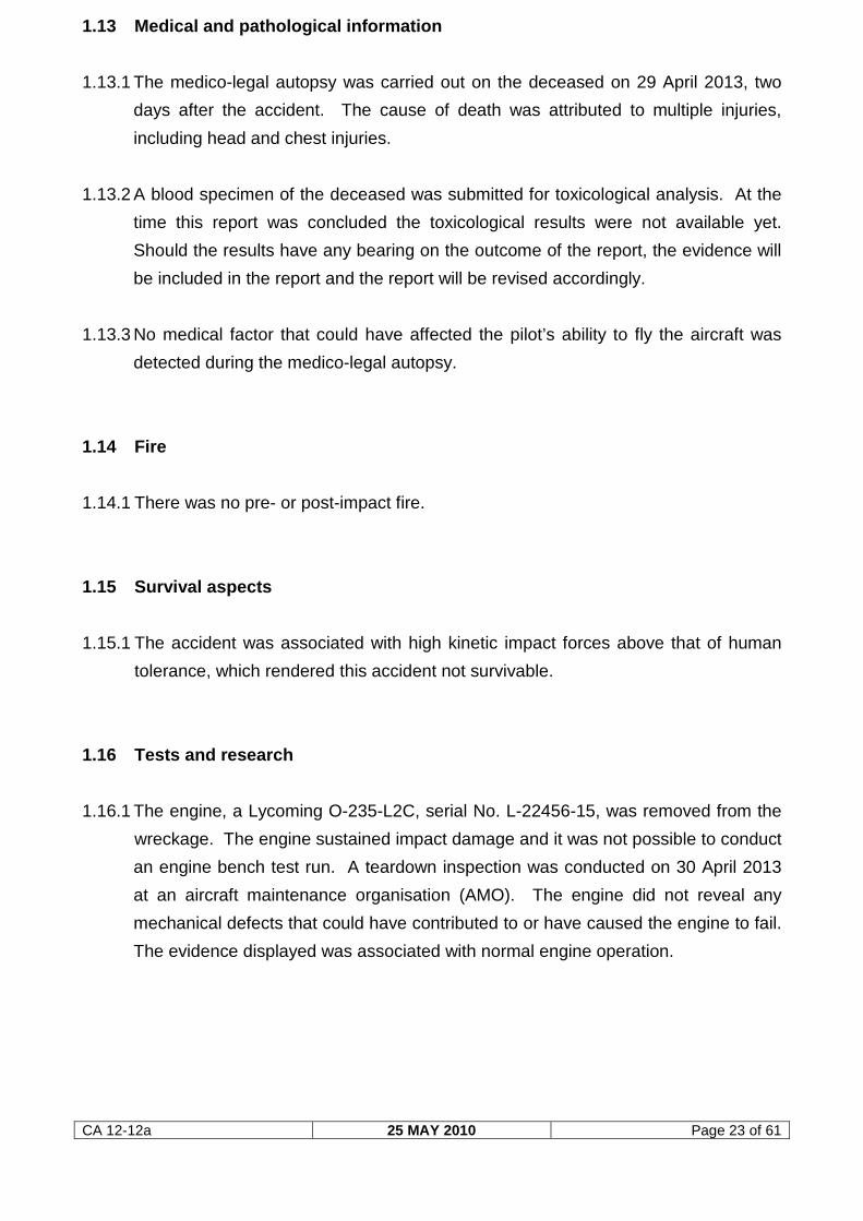
One of the propeller blades displayed signs of impact damage, with the blade tip
being bent backwards; the other blade as well as the spinner revealed no signs of
rotational scoring, as can be seen in figure 14 below. Cockpit examination revealed
that the carburettor heat selector lever was in, the throttle was in (maximum power
selected), and the mixture lever was about 1 cm out (very close to full rich).
Figure 14. A view of the propeller and front section of the aircraft.
CA 12-12a 25 MAY 2010 Page 23 of 61
1.13 Medical and pathological information
1.13.1 The medico-legal autopsy was carried out on the deceased on 29 April 2013, two
days after the accident. The cause of death was attributed to multiple injuries,
including head and chest injuries.
1.13.2 A blood specimen of the deceased was submitted for toxicological analysis. At the
time this report was concluded the toxicological results were not available yet.
Should the results have any bearing on the outcome of the report, the evidence will
be included in the report and the report will be revised accordingly.
1.13.3 No medical factor that could have affected the pilot’s ability to fly the aircraft was
detected during the medico-legal autopsy.
1.14 Fire
1.14.1 There was no pre- or post-impact fire.
1.15 Survival aspects
1.15.1 The accident was associated with high kinetic impact forces above that of human
tolerance, which rendered this accident not survivable.
1.16 Tests and research
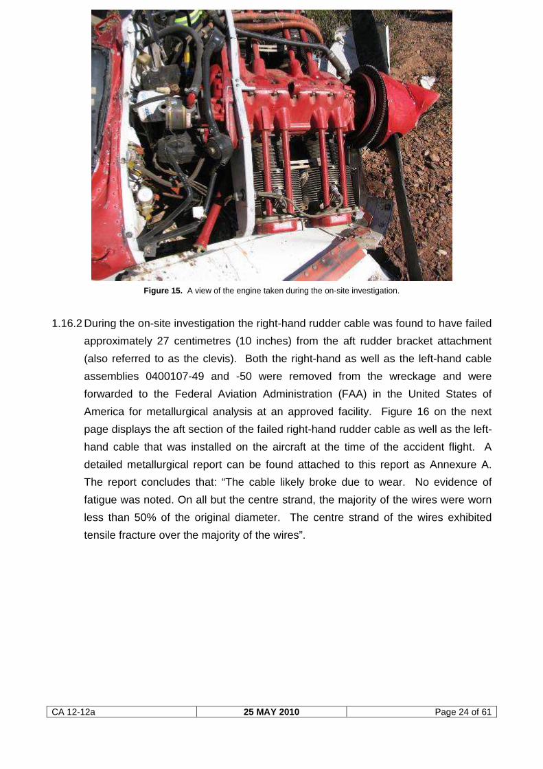
1.16.1 The engine, a Lycoming O-235-L2C, serial No. L-22456-15, was removed from the
wreckage. The engine sustained impact damage and it was not possible to conduct
an engine bench test run. A teardown inspection was conducted on 30 April 2013
at an aircraft maintenance organisation (AMO). The engine did not reveal any
mechanical defects that could have contributed to or have caused the engine to fail.
The evidence displayed was associated with normal engine operation.
CA 12-12a 25 MAY 2010 Page 24 of 61
Figure 15. A view of the engine taken during the on-site investigation.
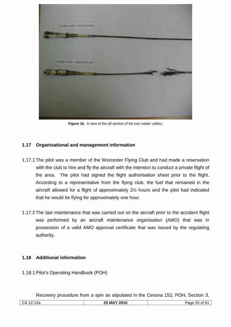
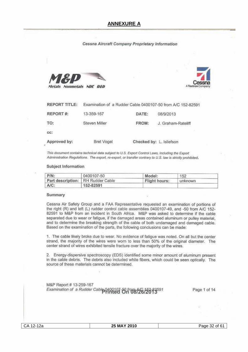
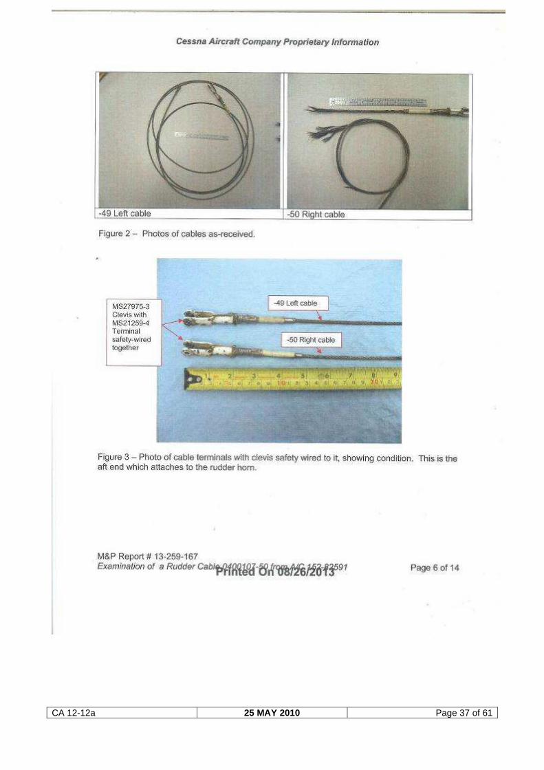
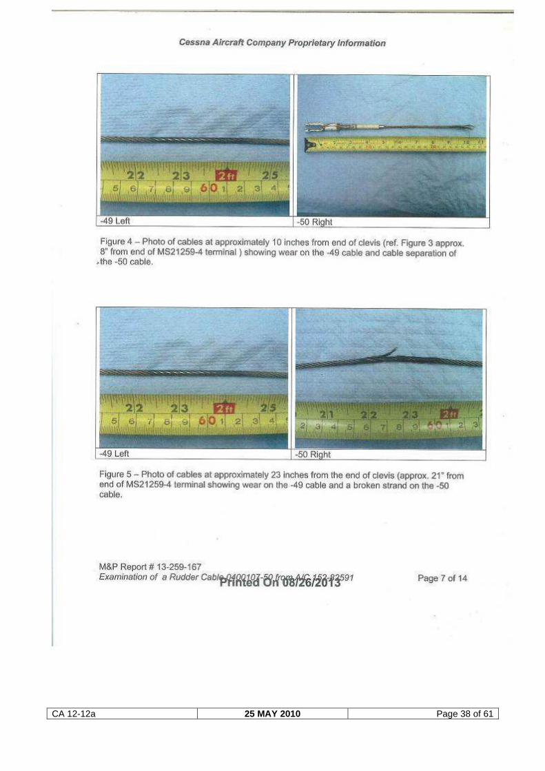
1.16.2 During the on-site investigation the right-hand rudder cable was found to have failed
approximately 27 centimetres (10 inches) from the aft rudder bracket attachment
(also referred to as the clevis). Both the right-hand as well as the left-hand cable
assemblies 0400107-49 and -50 were removed from the wreckage and were
forwarded to the Federal Aviation Administration (FAA) in the United States of
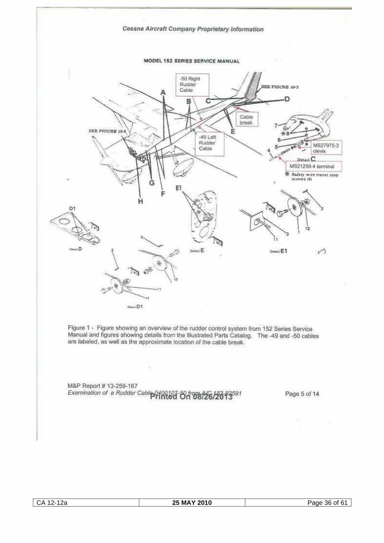
America for metallurgical analysis at an approved facility. Figure 16 on the next
page displays the aft section of the failed right-hand rudder cable as well as the left-
hand cable that was installed on the aircraft at the time of the accident flight. A
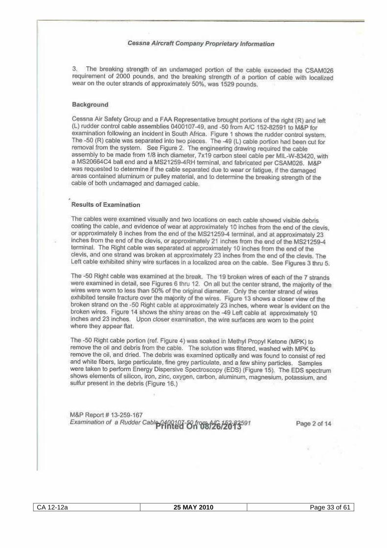
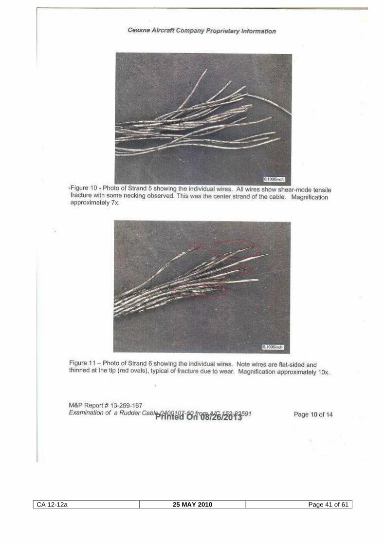
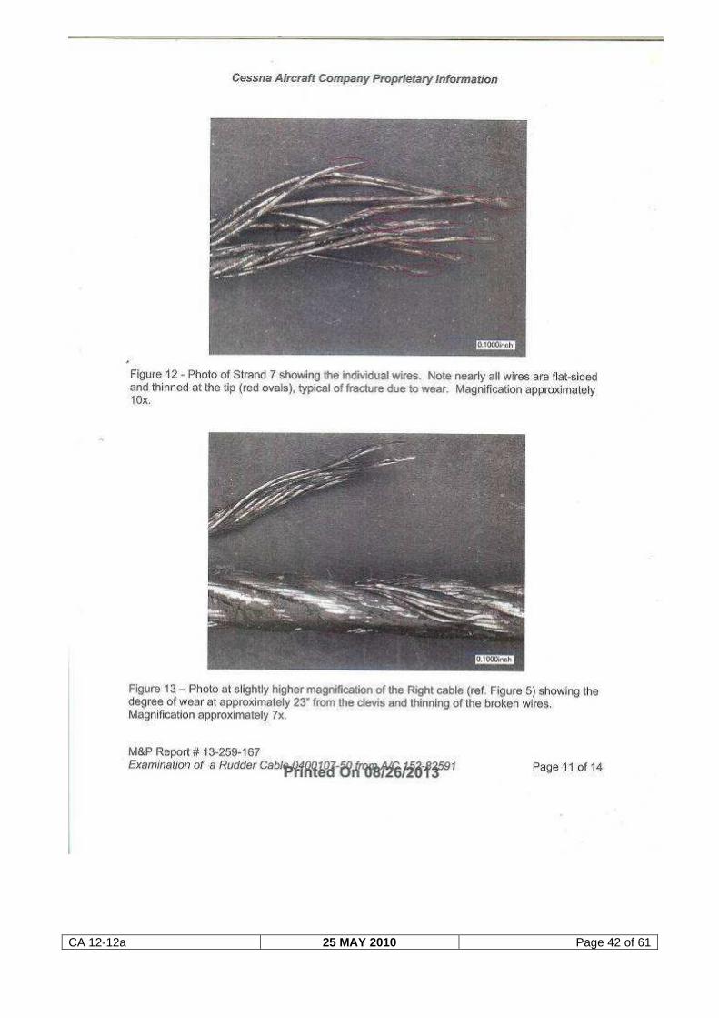
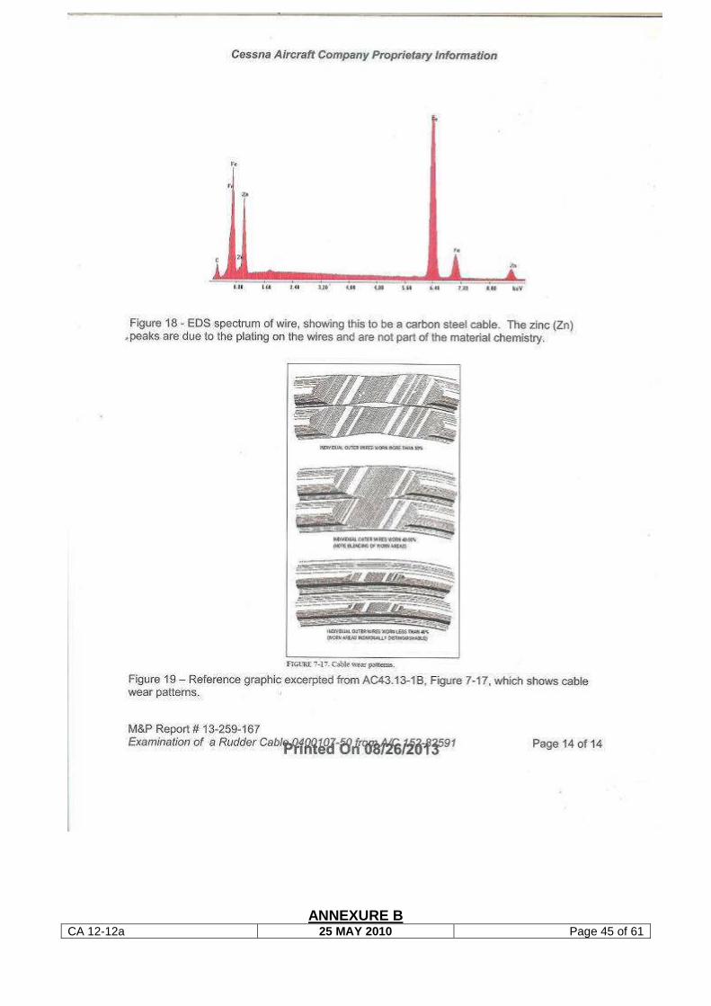
detailed metallurgical report can be found attached to this report as Annexure A.
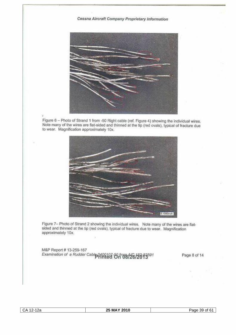
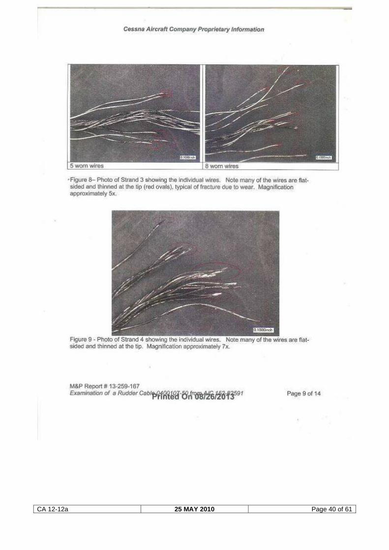
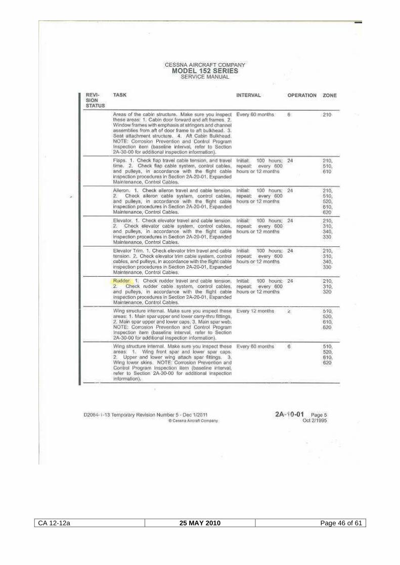
The report concludes that: “The cable likely broke due to wear. No evidence of
fatigue was noted. On all but the centre strand, the majority of the wires were worn
less than 50% of the original diameter. The centre strand of the wires exhibited
tensile fracture over the majority of the wires”.
CA 12-12a 25 MAY 2010 Page 25 of 61
Figure 16. A view of the aft section of the two rudder cables.
1.17 Organisational and management information
1.17.1 The pilot was a member of the Worcester Flying Club and had made a reservation
with the club to hire and fly the aircraft with the intention to conduct a private flight of
the area. The pilot had signed the flight authorisation sheet prior to the flight.
According to a representative from the flying club, the fuel that remained in the
aircraft allowed for a flight of approximately 2½ hours and the pilot had indicated
that he would be flying for approximately one hour.
1.17.2 The last maintenance that was carried out on the aircraft prior to the accident flight
was performed by an aircraft maintenance organisation (AMO) that was in
possession of a valid AMO approval certificate that was issued by the regulating
authority.
1.18 Additional information
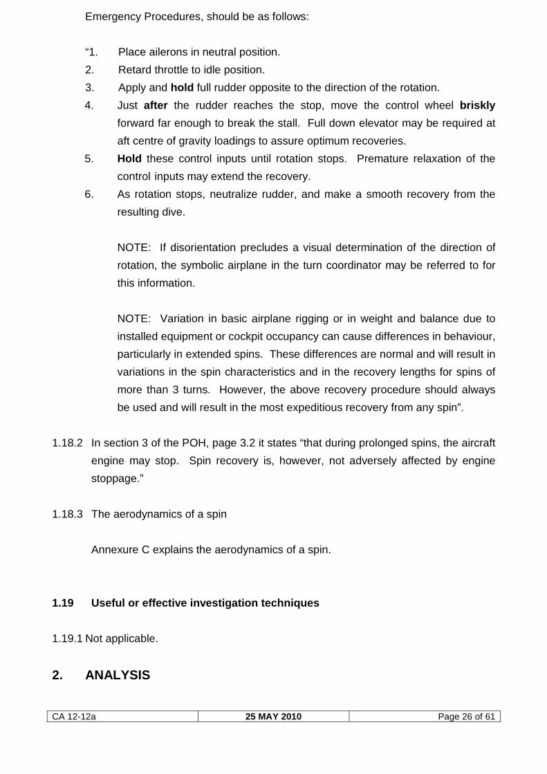
1.18.1 Pilot’s Operating Handbook (POH)
Recovery procedure from a spin as stipulated in the Cessna 152, POH, Section 3,
CA 12-12a 25 MAY 2010 Page 26 of 61
Emergency Procedures, should be as follows:
“1. Place ailerons in neutral position.
2. Retard throttle to idle position.
3. Apply and hold full rudder opposite to the direction of the rotation.
4. Just after the rudder reaches the stop, move the control wheel briskly
forward far enough to break the stall. Full down elevator may be required at
aft centre of gravity loadings to assure optimum recoveries.
5. Hold these control inputs until rotation stops. Premature relaxation of the
control inputs may extend the recovery.
6. As rotation stops, neutralize rudder, and make a smooth recovery from the
resulting dive.
NOTE: If disorientation precludes a visual determination of the direction of
rotation, the symbolic airplane in the turn coordinator may be referred to for
this information.
NOTE: Variation in basic airplane rigging or in weight and balance due to
installed equipment or cockpit occupancy can cause differences in behaviour,
particularly in extended spins. These differences are normal and will result in
variations in the spin characteristics and in the recovery lengths for spins of
more than 3 turns. However, the above recovery procedure should always
be used and will result in the most expeditious recovery from any spin”.
1.18.2 In section 3 of the POH, page 3.2 it states “that during prolonged spins, the aircraft
engine may stop. Spin recovery is, however, not adversely affected by engine
stoppage.”
1.18.3 The aerodynamics of a spin
Annexure C explains the aerodynamics of a spin.
1.19 Useful or effective investigation techniques
1.19.1 Not applicable.
2. ANALYSIS
CA 12-12a 25 MAY 2010 Page 27 of 61
2.1 Pilot (Man)
The pilot was the holder of a valid private pilot licence. He commenced with his
flying training as a student pilot on 18 December 1999 and at the time of the
accident flight had accumulated a total of 173,0 flying hours (this comprises training
hours (flying with a flight instructor) as well as solo flying hours). The pilot
maintained his private pilot licence throughout the years, and his last flight prior to
the accident flight was conducted on 6 April 2013 in the same aircraft.
The book “The Air Pilot’s Manual - 1 Flying Training” was located on the accident
scene (see figure 2, page 4 of this report). The possibility cannot be excluded that
the pilot intended to practise the three different flight manoeuvres highlighted by
page markers in the book. From the accident scene it was evident that the book
was not in his flying bag at the time, as the bag remained intact in the aft cabin area
and all compartments were closed. The book was most probably lying next to the
pilot on the right front seat during the flight. It should be noted that the accident
occurred approximately 15 minutes after take-off (this information is based on the
tachometer reading when compared with the last flight folio entry as found at the
accident scene).
From the eyewitness account it was very difficult to determine whether the pilot had
initiated the spin manoeuvre or whether it was unintentional. Following an
assessment of the wreckage, it could be ascertained that the aircraft was indeed in
a spin when it impacted the ground. For an aircraft to enter a spin, certain flight
criteria must be met, which indicate that the pilot most probably induced the
manoeuvre. Whether his intention was to enter a fully developed spin or to recover
following the incipient phase could not be determined, however. The aircraft
impacted the ground while still in a spin. No medical factor that could have affected
the pilot’s ability to fly the aircraft was detected during the medico-legal autopsy.
2.2 Aircraft (Machine)
The aircraft was manufactured in 1979 and was imported into South Africa from the
United States of America in March 2008. The airframe hours entered into the South
African logbook indicates that the aircraft had accumulated 9 700 hours since new
when it arrived in South Africa. Over the period March 2008 until November 2011,
fourteen (14) mandatory periodic inspections were carried out on the aircraft in
South Africa prior to the accident flight, which constitute a further 1 300 airframe
hours. An additional 86,1 hours were flown with the aircraft after the last MPI was
CA 12-12a 25 MAY 2010 Page 28 of 61
certified until the accident flight.
The aircraft was subjected to the required maintenance inspections since it was
imported into South Africa and all the inspections were conducted under the
auspices of an approved aircraft maintenance organisation. The aircraft was in
possession of a valid certificate of airworthiness at the time of the accident flight.
The rudder cables installed on this aircraft were ‘on condition’ items, which means
they have no defined service life prescribed by the aircraft manufacturer and are
replaced following assessment of the condition of the cables during maintenance
inspections. The Cessna 152 Service Manual, read in conjunction with the
expanded maintenance procedure 2A-20-01 (Control Cables) attached to this report
as Annexure B, provides clear guidelines to maintenance personnel on how to
inspect these cables during every prescribed maintenance inspection. The
expanded maintenance procedure provides maintenance personnel with the
required information on when these cables need to be replaced should any
discrepancy be detected that could impair/jeopardise the integrity of such cables.
This is of paramount importance with reference to flight control cables.
According to available maintenance records these inspections where complied with
by the AMO during routine maintenance. No documented evidence could be
obtained that either of the rudder cables were replaced after the aircraft was
imported into South Africa in 2008.
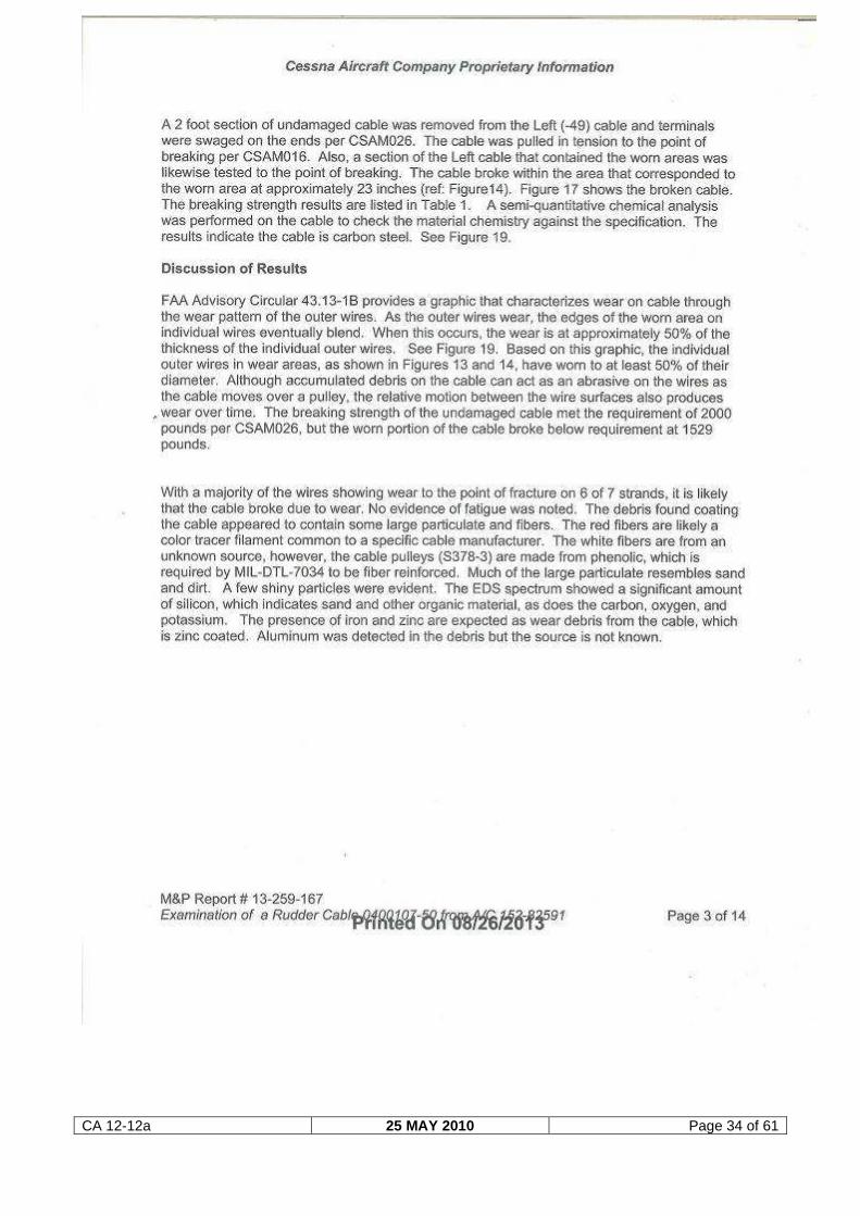
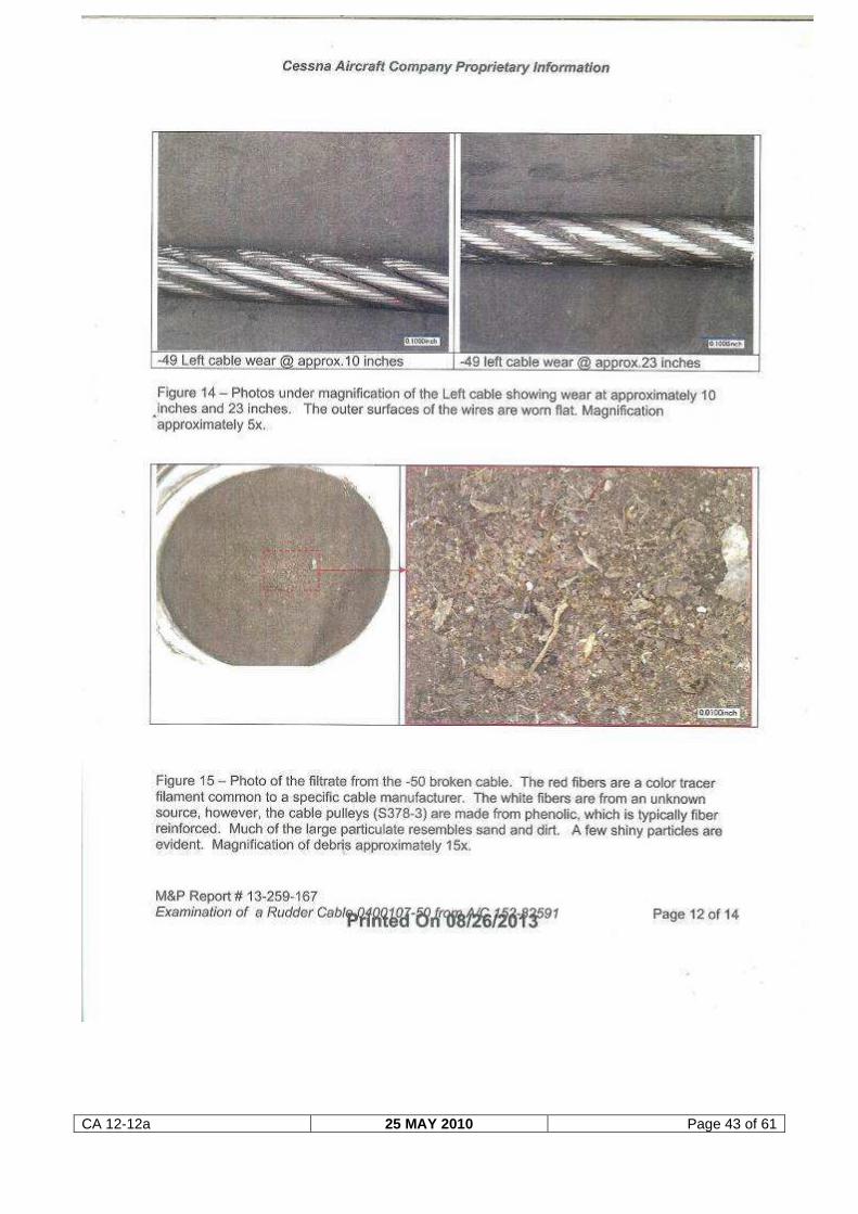
The metallurgical report indicates that the right-hand rudder cable had failed due to
mechanical wear, which progressed over an undetermined period of time. The left-
hand cable also displayed evidence of wear, but the wear had not reached such an
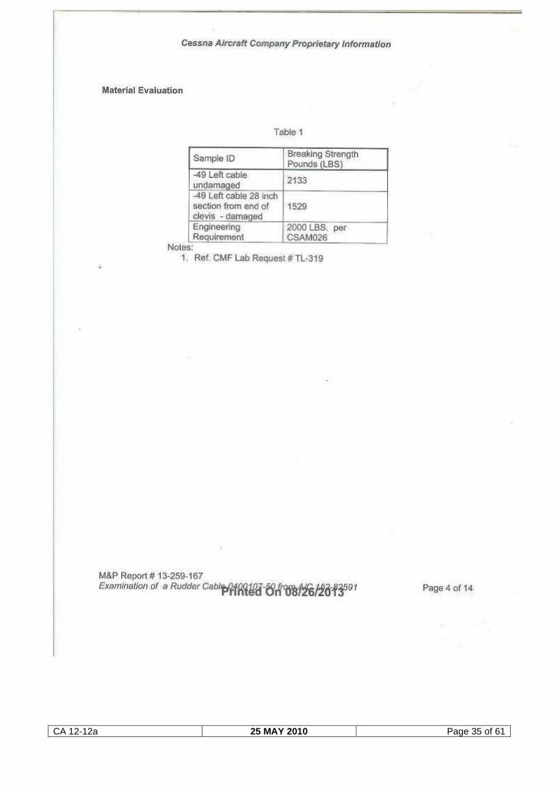
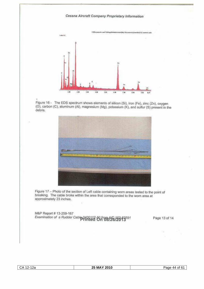
advanced state as the right-hand cable, which failed in operation. A breaking
strength test was performed on the left-hand cable and it failed in the area where
the wear was present, which was well below the 2 000 pounds engineering limit.
2.3 Mission
The aircraft was hired from the flying club by the pilot with the intention to conduct a
private flight. The possibility that the pilot could have opted to practise certain flying
manoeuvres as marked in the book that was found on site, namely “The Air Pilot’s
Manual, 1 Flying Training, by Trevor Thom, which include spins, forced landings
and precautionary landings, cannot be excluded. In order for the aircraft to enter
into a spin the pilot had to initiate such a manoeuvre by entering a condition of
CA 12-12a 25 MAY 2010 Page 29 of 61
stalled flight (high angle of attack), whereby a wing drop is essential to enter a spin;
this may occur by itself or (more likely) be induced by the pilot yawing the aircraft.
Ground impact markings and wreckage deformation indicate that the aircraft was in
a spin when it collided with the ground. The intention of the pilot might not have
been to enter a fully developed spin, but to recover following the incipient phase.
However, the incipient phase also requires the pilot to apply sufficient rudder to
prevent further yaw.
2.4 Environment
Fine weather conditions prevailed at the time of the flight and were not
considered to have had a bearing on the accident. The pilot was familiar with the
area, as he had flown there on many previous occasions, having been a member of
the Worcester Flying Club since 2002.
2.5 Conclusion
The examination of the wreckage suggested that the aircraft impacted the ground
with very little forward velocity, but with a substantial vertical component associated
with a high rate of descent (illustrated by the compression of the wreckage).
The wreckage showed slightly more damage on the left wing than the right wing;
the deformation of the fuselage (especially the nose section) displayed a clear twist
towards the left, which was indicative of an aircraft that had entered a spin to the
left.
The fact that the propeller and spinner displayed very little signs of rotation on
impact could be an indication that the engine had stopped prior to the aircraft
impacting the ground. The POH of the aircraft states that prolonged spinning could
cause engine stoppage, but that this should not adversely affect spin recovery.
In view of the handbook found in the cockpit area with the exercise in spin recovery
highlighted, the pilot may have been practising this exercise. It is unlikely that the
aircraft had entered a turn to the left and subsequently a spiral dive due to the
failure of the right-hand rudder cable.
It could, however, not be determined at what stage during the flight the cable failed.
An essential part of the recovery technique from a spin is that the pilot should check
throttle close and apply full opposite rudder. Taking into consideration that the cable
was found to be in a state of wear, the cable most probably failed when the pilot
applied full opposite rudder, which in this case would have been right rudder, in
CA 12-12a 25 MAY 2010 Page 30 of 61
order to recover from the spin manoeuvre. Following the failure of the cable the
pilot had no rudder authority to counteract the yaw rate and the aircraft continued to
spin towards the left until it impacted the ground.
3. CONCLUSION
3.1 Findings
3.1.1 The pilot was the holder of a valid private pilot licence and had the aircraft type
endorsed on his licence.
3.1.2 The pilot was the holder of a valid aviation medical certificate that was issued by a
CAA-approved medical examiner.
3.1.3 No medical factor that could have affected the pilot’s ability to fly the aircraft was
detected during the medico-legal autopsy.
3.1.4 The aircraft was in possession of a valid certificate of airworthiness at the time of
the accident flight.
3.1.5 The aircraft had accumulated a further 86,1 flying hours since the last MPI
inspection prior to the accident flight was certified on the aircraft, dated 16
November 2012.
3.1.6 The aircraft weight and balance and centre of gravity (CG) were found to be within
the prescribed limits as stipulated in Section 6 of the POH.
3.1.7 During the on-site investigation it was found that the right-hand rudder cable had
failed. The failure mode was attributed to mechanical wear. The wear occurred
over an undetermined period of time.
3.1.8 Wear damage on the right-hand cable at other locations suggested extended
operational exposure.
3.1.9 Although to a lesser degree, the left-hand rudder cable revealed similar damage.
During a strength test that was conducted on the cable it failed in the area where
wear was present.
3.1.10 Fine weather conditions prevailed at the time of the flight; the wind was from the
CA 12-12a 25 MAY 2010 Page 31 of 61
west at 12 knots gusting 23 knots, with clear sky conditions.
3.2 Probable cause:
3.2.1 The right-hand rudder cable was found to have failed, this most probably rendered
the pilot without rudder authority to counteract the spin and recover from the
manoeuvre.
4. SAFETY RECOMMENDATIONS
4.1 It is recommended to the Director of Civil Aviation that the Airworthiness division
issue an Urgent Safety Advisory Notice to all Cessna 150/152 owners to ensure
rudder cable integrity is not compromised in any way. A detailed inspection of the
rudder cables (from the front to the back) should be conducted by an approved
aircraft maintenance organisation. Such an inspection should be documented in the
aircraft airframe logbook and should not be limited to a once-off inspection.
This safety recommendation was issued in the interest of aviation safety.
5. APPENDICES
5.1 Annexure A (Metallurgical report on rudder cables)
5.2 Annexure B (Cessna 152 Service Manual and expanded maintenance procedure)
5.3 Annexure C (The aerodynamics of a spin)
CA 12-12a 25 MAY 2010 Page 32 of 61
ANNEXURE A
CA 12-12a 25 MAY 2010 Page 33 of 61
CA 12-12a 25 MAY 2010 Page 34 of 61
CA 12-12a 25 MAY 2010 Page 35 of 61
CA 12-12a 25 MAY 2010 Page 36 of 61
CA 12-12a 25 MAY 2010 Page 37 of 61
CA 12-12a 25 MAY 2010 Page 38 of 61
CA 12-12a 25 MAY 2010 Page 39 of 61
CA 12-12a 25 MAY 2010 Page 40 of 61
CA 12-12a 25 MAY 2010 Page 41 of 61
CA 12-12a 25 MAY 2010 Page 42 of 61
CA 12-12a 25 MAY 2010 Page 43 of 61
CA 12-12a 25 MAY 2010 Page 44 of 61
CA 12-12a 25 MAY 2010 Page 45 of 61
ANNEXURE B
CA 12-12a 25 MAY 2010 Page 46 of 61
CA 12-12a 25 MAY 2010 Page 47 of 61
CA 12-12a 25 MAY 2010 Page 48 of 61
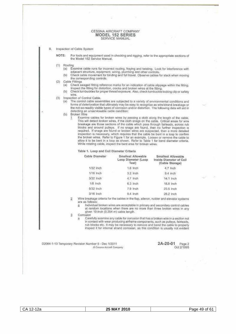
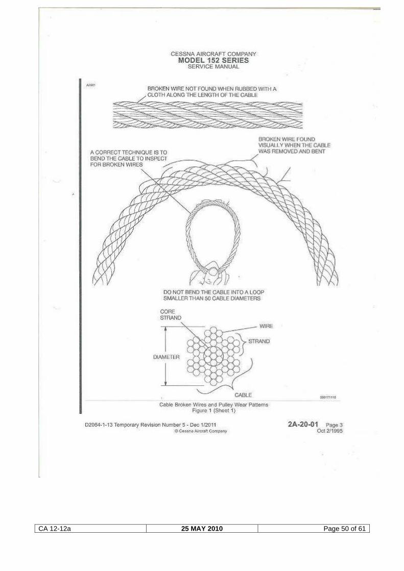
CA 12-12a 25 MAY 2010 Page 49 of 61
CA 12-12a 25 MAY 2010 Page 50 of 61
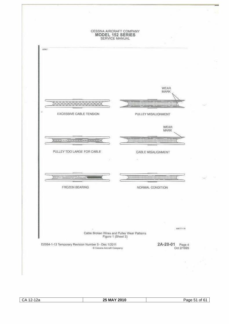
CA 12-12a 25 MAY 2010 Page 51 of 61
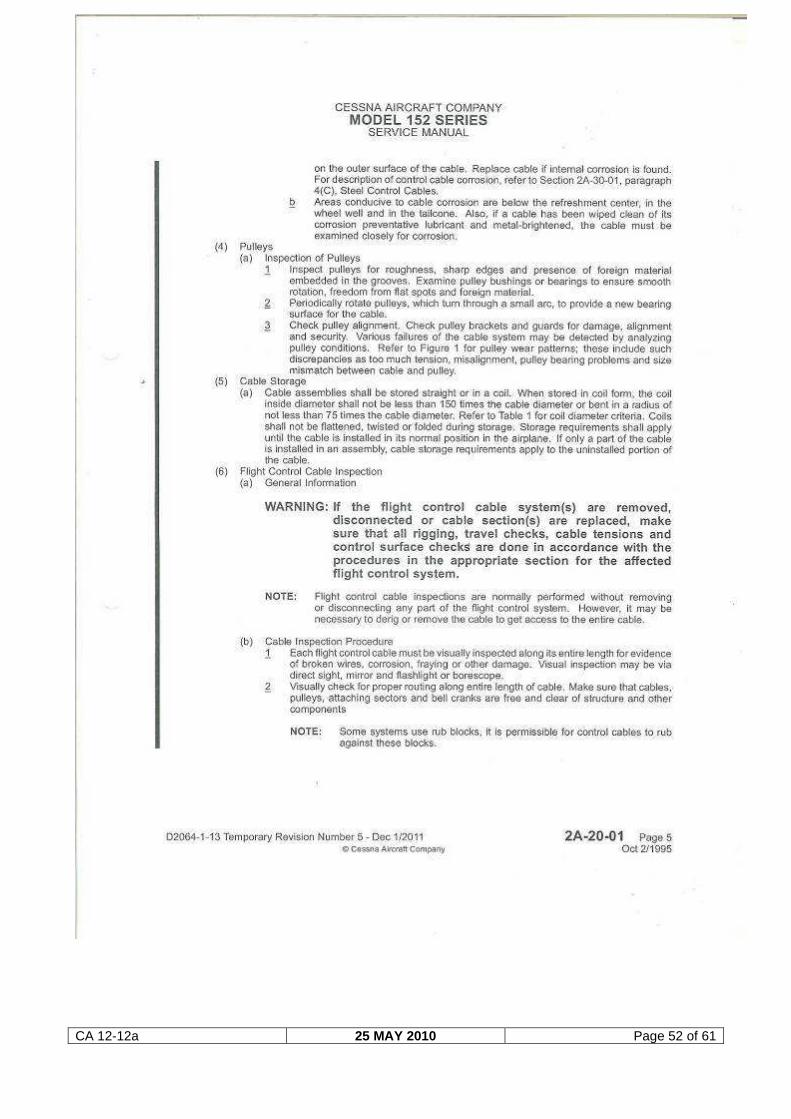
CA 12-12a 25 MAY 2010 Page 52 of 61
CA 12-12a 25 MAY 2010 Page 53 of 61
CA 12-12a 25 MAY 2010 Page 54 of 61
ANNEXURE C
The aerodynamics of a spin
Source: www.copanational.org/PilotsPrimer (Canadian Owners and Pilots Association)
“If pilots were to get together and rank the most dangerous situations they could encounter
over the course of a flight, stall/spin incidents would be near the top.
While stall/spin accidents are not as frequent as other types of accidents, they are in
general more deadly. The statistics show that although stall/spin encounters make up only
8% of all general aviation accidents, they account for 25% of the accidents involving
serious or fatal injuries. Therefore, general knowledge of spins is stressed throughout pilot
training and reiterated in aviation publications.
However, a deeper understanding of spins is commonly lacking among the majority of the
pilot population. Hopefully this article will shed light on some of the basic aerodynamic
principles that govern the behaviour of aircraft before, during, and after a spin is
encountered.
To understand the aerodynamics of a spin, it is important to first understand how lift and
drag behave at high angles of attack. This includes not only an understanding of what
happens to lift and drag near stall, but also where the stall occurs along the span of the
wing.
It is convention to say that a stall occurs when the aircraft exceeds its critical angle of
attack. Aerodynamically speaking, this means that at the critical angle of attack, separated
flow dominates the airflow over the wing resulting in a decrease in lift and an increase in
drag. The location along the wingspan where the stall begins depends on many factors
including the wing planform and any stall control device installed on the wing.
Typically, a wing is designed to stall from root to tip, resulting in more effective aileron
control during stall. This is important in understanding the effect of aileron input during spin
recovery, and will be discussed a little later in the article.
The generally accepted definition of a spin is an aggravated stall that results in
autorotation. This is an accurate and concise definition, but it does not explain or provide
good understanding to the underlying cause and persistence of a spin.
The aerodynamics of a spin are very complicated, and for ease of understanding the
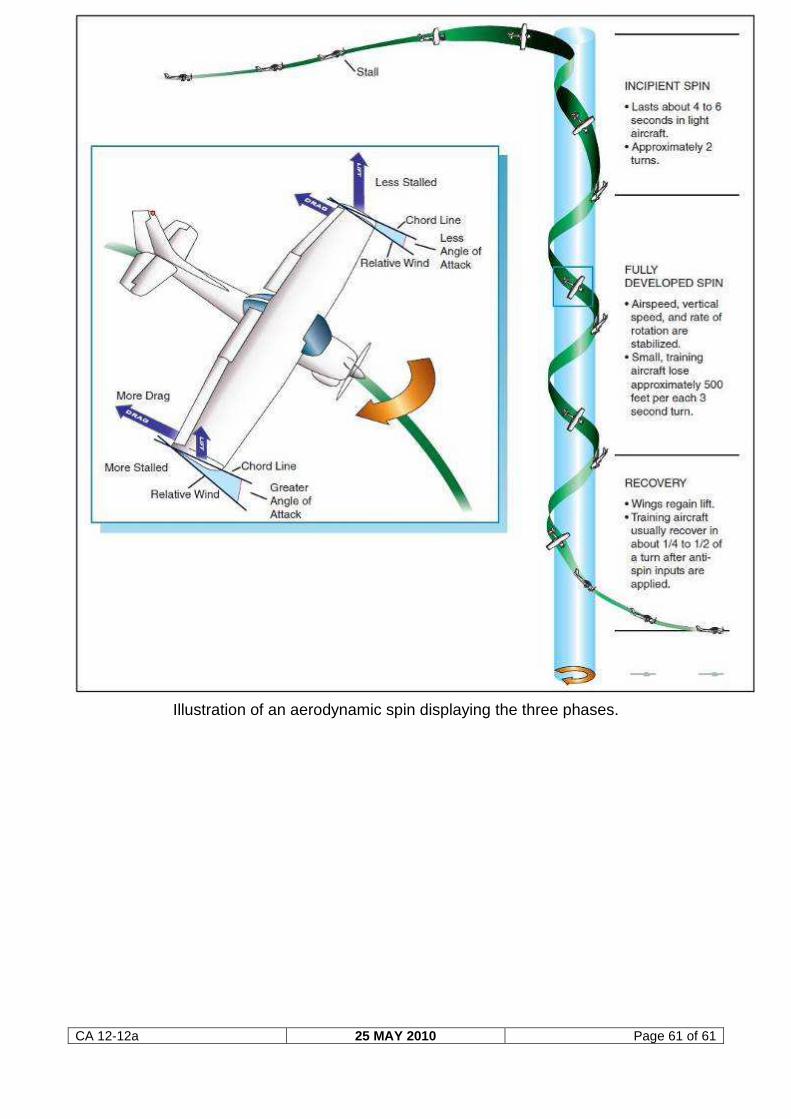
aerodynamics of each phase of a spin should be analyzed separately. The phases of a
spin are: entry, incipient, and fully developed.
CA 12-12a 25 MAY 2010 Page 55 of 61
The entry phase begins with the aggravated stall and ends when the aircraft departs
controlled flight. The incipient phase occurs between the departure from controlled flight
and the point when the forces acting on the aircraft equilibrate. The fully developed phase
is characterized by equilibrium between the aerodynamic and inertial forces.
The entry phase of a spin is characterized by an aggravated stall, causing the aircraft to
depart controlled flight. A stall can become aggravated in two ways: a prolonged slip (or
more importantly a skid) or a sudden yawing motion at the time of stall.
To answer the question why a prolonged slip aggravates a stall you must first understand
that as an airplane slows down, its natural roll damping decreases. This means that the
inherent stability of the airplane to keep wings level decreases with airspeed, which makes
it much harder to keep wings level in a slip or skid.
Eventually it will result in a rolling motion in the direction of the prolonged slip or skid.
This rolling motion induces a higher angle of attack on the downward wing, resulting in an
aggravated stall situation where the downward wing is more stalled than the upward wing.
A sudden yawing motion at the time of stall causes the outside wing to travel faster than
the inside wing.
This creates more lift on the outside wing compared to the inside wing, which results in
rolling motion toward the inside wing and causes the inside wing to be at a higher angle of
attack than the outside wing. In either case the airplane enters a state of aggravated stall
where one wing is stalled more than the other.
The wing that is more stalled creates more drag and less lift than the less stalled wing, and
this imbalance of forces pulls the aircraft away from controlled flight in the direction of the
more stalled wing.
CA 12-12a 25 MAY 2010 Page 56 of 61
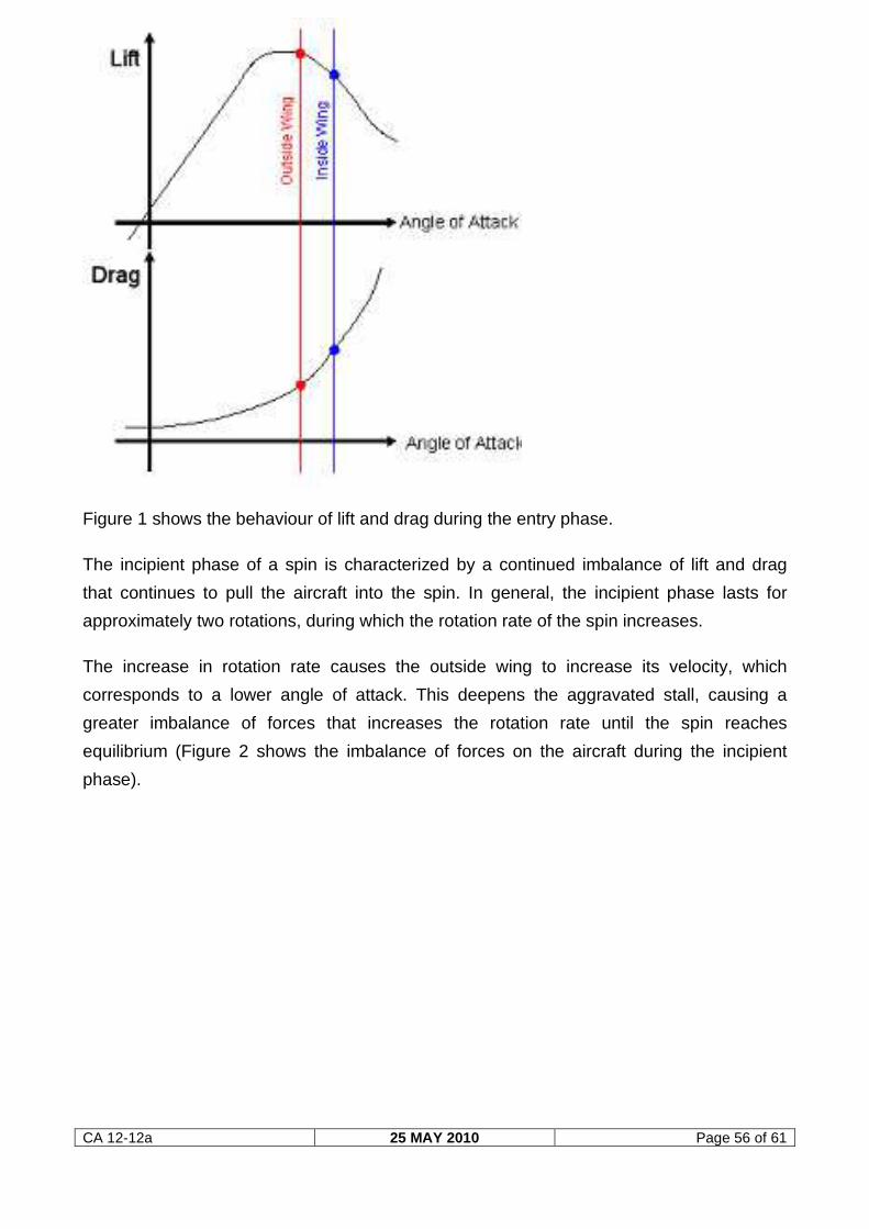
Figure 1 shows the behaviour of lift and drag during the entry phase.
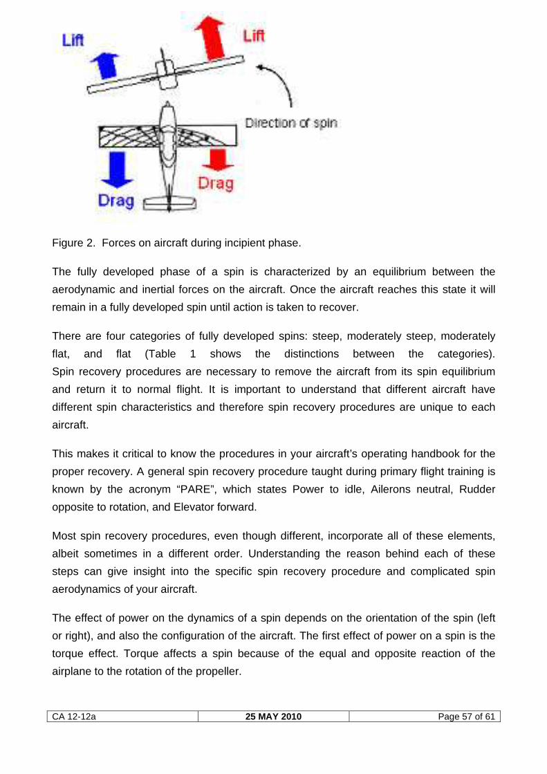
The incipient phase of a spin is characterized by a continued imbalance of lift and drag
that continues to pull the aircraft into the spin. In general, the incipient phase lasts for
approximately two rotations, during which the rotation rate of the spin increases.
The increase in rotation rate causes the outside wing to increase its velocity, which
corresponds to a lower angle of attack. This deepens the aggravated stall, causing a
greater imbalance of forces that increases the rotation rate until the spin reaches
equilibrium (Figure 2 shows the imbalance of forces on the aircraft during the incipient
phase).
CA 12-12a 25 MAY 2010 Page 57 of 61
Figure 2. Forces on aircraft during incipient phase.
The fully developed phase of a spin is characterized by an equilibrium between the
aerodynamic and inertial forces on the aircraft. Once the aircraft reaches this state it will
remain in a fully developed spin until action is taken to recover.
There are four categories of fully developed spins: steep, moderately steep, moderately
flat, and flat (Table 1 shows the distinctions between the categories).
Spin recovery procedures are necessary to remove the aircraft from its spin equilibrium
and return it to normal flight. It is important to understand that different aircraft have
different spin characteristics and therefore spin recovery procedures are unique to each
aircraft.
This makes it critical to know the procedures in your aircraft’s operating handbook for the
proper recovery. A general spin recovery procedure taught during primary flight training is
known by the acronym “PARE”, which states Power to idle, Ailerons neutral, Rudder
opposite to rotation, and Elevator forward.
Most spin recovery procedures, even though different, incorporate all of these elements,
albeit sometimes in a different order. Understanding the reason behind each of these
steps can give insight into the specific spin recovery procedure and complicated spin
aerodynamics of your aircraft.
The effect of power on the dynamics of a spin depends on the orientation of the spin (left
or right), and also the configuration of the aircraft. The first effect of power on a spin is the
torque effect. Torque affects a spin because of the equal and opposite reaction of the
airplane to the rotation of the propeller.
CA 12-12a 25 MAY 2010 Page 58 of 61
For a propeller that rotates clockwise when viewed by the pilot, torque acts to tighten a left
spin and flatten a right spin. The second effect of power is the gyroscopic effect. For a
propeller that rotates clockwise as viewed by the pilot, a gyroscopic force acts to raise the
nose in a left spin and lower the nose in a right spin.
The last effect of power is a thrust line effect, where the thrust line is a line parallel to the
longitudinal axis of the airplane along which the thrust acts. If this line is below the centre
of gravity (CG) of the aircraft, power results in a flatter spin. The opposite is the case if the
thrust line is above the centre of gravity.
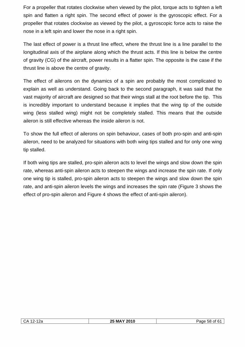
The effect of ailerons on the dynamics of a spin are probably the most complicated to
explain as well as understand. Going back to the second paragraph, it was said that the
vast majority of aircraft are designed so that their wings stall at the root before the tip. This
is incredibly important to understand because it implies that the wing tip of the outside
wing (less stalled wing) might not be completely stalled. This means that the outside
aileron is still effective whereas the inside aileron is not.
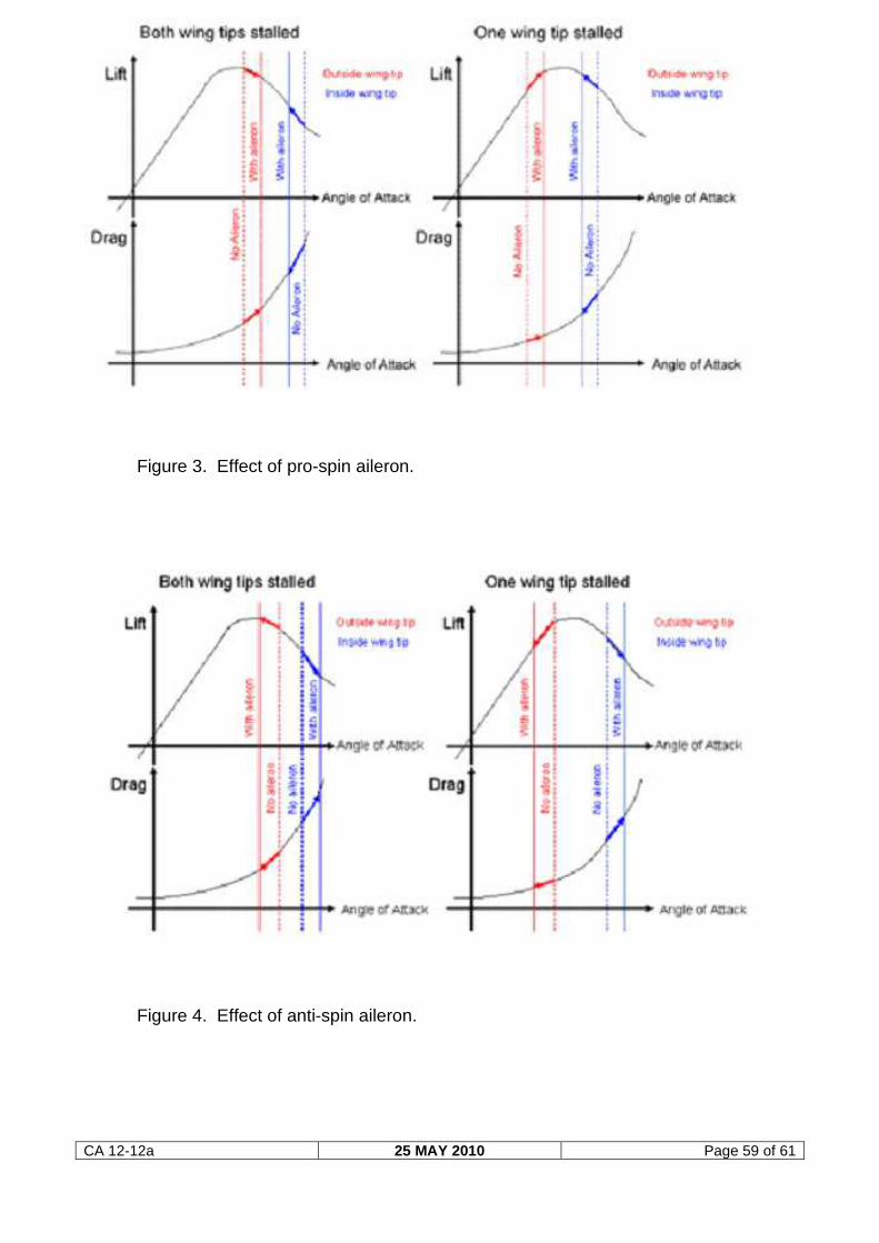
To show the full effect of ailerons on spin behaviour, cases of both pro-spin and anti-spin
aileron, need to be analyzed for situations with both wing tips stalled and for only one wing
tip stalled.
If both wing tips are stalled, pro-spin aileron acts to level the wings and slow down the spin
rate, whereas anti-spin aileron acts to steepen the wings and increase the spin rate. If only
one wing tip is stalled, pro-spin aileron acts to steepen the wings and slow down the spin
rate, and anti-spin aileron levels the wings and increases the spin rate (Figure 3 shows the
effect of pro-spin aileron and Figure 4 shows the effect of anti-spin aileron).
CA 12-12a 25 MAY 2010 Page 59 of 61
Figure 3. Effect of pro-spin aileron.
Figure 4. Effect of anti-spin aileron.
CA 12-12a 25 MAY 2010 Page 60 of 61
From a practical standpoint it is hard to know if one or both of your wing tips are stalled
during a spin. Therefore, the best course of action during recovery is to keep the ailerons
neutral because you do not know if aileron application will help or hurt recovery.
The last two steps of the general spin recovery procedure are relatively straightforward to
understand. The rudder opposite rotation is used to stop the rotation of the spin, and the
elevator forward step is to break the stall (decrease the angle of attack) so that the aircraft
can be returned to normal flight.
Understanding the aerodynamics behind spins helps the pilot better understand how his or
her airplane flies. Of course the critical point in all this is that the aircraft must be stalled in
order to spin. No stall, no spin!
As a result, it’s important to be proficient at stall recovery so that the spin condition is
never reached. Especially at low altitude, successful spin recovery may be difficult if not
impossible in many aircraft.
Many pilots also find it educational to seek out spin training so that if a spin is inadvertently
encountered they will know what to expect and also how to make an effective recovery. If
you haven’t had spin training, consider seeking some instruction in this area. The life you
save by having spin recognition and recovery skills may be your own!”
CA 12-12a 25 MAY 2010 Page 61 of 61
Illustration of an aerodynamic spin displaying the three phases.