SECTION C3.2 STANDARD SPECIFICATION FOR … EPS - (C3.2...The multiplexer shall be compatible with...
27
Contract Section C3.2 C3.4 Construction Standard Electronic Specification Reference No. CTIA RFB 39 - 2016 C3-361 SECTION C3.2 STANDARD SPECIFICATION FOR CONTROL & INSTRUMENTATION INSTALLATIONS CONTENTS 1 PROGRAMMABLE LOGIC CONTROLLERS (PLCs) ....................................................... C3-362 2 HUMAN MACHINE INTERFACE ....................................................................................... C3-366 3 SUPERVISORY CONTROL AND DATA ACQUISITION (SCADA) .................................. C3-367 4 INTERFACING OF PLCs WITH SWITCHGEAR / CONTROLGEAR AND OTHER ELECTRONIC SYSTEMS ................................................................................................... C3-374 5 POWER, CONTROL AND INSTRUMENTATION CABLES & WIRING ............................ C3-375 6 OPTICAL FIBER CABLE ................................................................................................... C3-378 7 FIELD INSTRUMENTATION ............................................................................................. C3-380 8 UNINTERRUPTABLE POWER SUPPLIES ...................................................................... C3-385 9 RADIO, TELEVISION, COMPUTER AND COMPUTER SYSTEM INTERFERENCE ....... C3-386 10 OPERATION AND MAINTENANCE MANUALS ............................................................... C3-386
Transcript of SECTION C3.2 STANDARD SPECIFICATION FOR … EPS - (C3.2...The multiplexer shall be compatible with...

Contract Section C3.2 C3.4 Construction Standard Electronic Specification Reference No. CTIA RFB 39 - 2016
C3-361
SECTION C3.2
STANDARD SPECIFICATION FOR CONTROL & INSTRUMENTATION INSTALLATIONS
CONTENTS
1 PROGRAMMABLE LOGIC CONTROLLERS (PLCs) ....................................................... C3-362
2 HUMAN MACHINE INTERFACE ....................................................................................... C3-366
3 SUPERVISORY CONTROL AND DATA ACQUISITION (SCADA) .................................. C3-367
4 INTERFACING OF PLCs WITH SWITCHGEAR / CONTROLGEAR AND OTHER ELECTRONIC SYSTEMS ................................................................................................... C3-374
5 POWER, CONTROL AND INSTRUMENTATION CABLES & WIRING ............................ C3-375
6 OPTICAL FIBER CABLE ................................................................................................... C3-378
7 FIELD INSTRUMENTATION ............................................................................................. C3-380
8 UNINTERRUPTABLE POWER SUPPLIES ...................................................................... C3-385
9 RADIO, TELEVISION, COMPUTER AND COMPUTER SYSTEM INTERFERENCE ....... C3-386
10 OPERATION AND MAINTENANCE MANUALS ............................................................... C3-386

Contract Section C3.2 C3.4 Construction Standard Electronic Specification Reference No. CTIA RFB 39 - 2016
C3-362
1 PROGRAMMABLE LOGIC CONTROLLERS (PLCs)
All PLCs, software programming and associated equipment shall be supplied and installed as per this Standard Electronic Specification, and as varied by the Detailed Electronic Specification.
1.1 General
A standalone programmable logic controller (PLC) shall be provided for the control of the equipment as described in the “Control Philosophy” section of the Detailed Specification or the Project Specification. Allowance shall be made within the PLC equipment supplied for the future control of the entire existing and proposed plant as described in the specification and as detailed with the Proposed Single Line Diagram as referred to in the Project Specification. Programmable logic controllers shall be supplied and installed where no communication is required to intelligent electronic devices, and where communication is required to intelligent electronic devices (e.g. motor protection relays, VSD’s etc.).
1.2 PLC Equipment Specification 1.2.1 Hardware shall be field-proven under similar conditions and shall be suitably protected against
excessive temperature, electrical interface, input and output overvoltage or short-circuit, and loss of program memory. The equipment supplied shall incorporate a non-volatile form of program memory, which does not rely on an internal or external source of power to retain program memory in the event of a loss of normal power.
1.2.2 The CPU and I/O modules of the PLC shall be supplied with 20% excess program memory and I/O capacity for initial operation of all specified process components. However, the specifications of the PLC shall allow for future expansion of up to 50% additional memory and I/O capacity.
It shall be noted that the latest "machine control" PLC shall be provided. Preferred suppliers are as
follows:
• Allen Bradley
• ABB
• Schneider Electric
• Siemens
• Eaton
The PLC's CPUs shall conform to the follow specifications:
CPU Type (As per Detailed Specification)
Discrete IO 1024
Analaog IO 256
Communications Interfaces Ethernet TCP/IP, Serial
Internal Memory 3584Kb for Program, 256Kb for Data
1.2.3 The PLC system shall be of a modular design with the mounting racks for the central controller, extension racks, power supply cards, central processing units interface cards, I/O cards, etc. interchangeable between the various nodes.

Contract Section C3.2 C3.4 Construction Standard Electronic Specification Reference No. CTIA RFB 39 - 2016
C3-363
1.2.4 It shall be possible to code cards and slots to prevent the incorrect card being inserted into a given slot. Alternatively, the controller shall employ interrogation software, which shall detect the insertion of an incorrect module and prevent controller operation if an incorrect module is installed.
1.2.5 It shall be possible to change the modules without disturbing field writing. Connection blocks shall plug into the modules and shall be coded, to prevent connection blocks being plugged into the wrong modules. All modules shall have surge protection, which meets the IEEE-472 or similar standard.
1.2.6 All inputs shall have LED status indication on the modules. A maximum of 8 inputs with a single neutral shall be provided per module.
1.2.7 Output modules shall be of the opto-electric switched solid state relay (SSR) type. The module shall be able to withstand a peak load of 15A for one cycle and intermittent load of 9A for 3 cycles, per channel. For SSR type output modules, fuse terminals with blown fuse indicators shall be provided at the back of the PLC section of the board. Should the fuse fail to blow, then the fault shall only affect the switched output, and shall not affect the remaining outputs within the group. All outputs shall have LED indications. For both the input and output modules, the LED’s shall give a true load – side indication to and from the field devices.
1.2.8 Analogue input modules shall be of the multiple input range type. This may be either by means of plug-in type measuring range cards or by dip-switch selection. The input resolution of the module shall be a minimum of 12 bits. All inputs shall be individually isolated. Input modules with LED indication for “Communication Active” and “Out of Range” are preferred. Where a large number of analogue inputs with relatively slow changing values are required to be monitored, use may be made of analogue multiplexer modules. The multiplexer shall be compatible with the analogue input module and shall therefore be supplied by the same manufacturer. The input resolution of the multiplexer shall be 12 bits.
1.2.9 Analogue output modules need not necessarily be of the full multiple output range type. The output resolution shall be 12 bits. The outputs shall be electrically isolated from each other. Output modules with “Communication Active” indicators are preferred. Galvanic isolation in the form of opto-isolators shall be provided for all inputs and outputs and the driving logic of the modules.
1.3 PLC Inputs and Outputs (I/O) This installation shall use mainly intelligent communications interfaces to control equipment and
instrumentation however where these are not available or practical, conventional input and output loops will be required.
Digital I/O cards for conventional signals shall be capable of 24 V dc input and output signals and
analog I/O cards shall be suitable for 4-20mA current loops.
The Detailed Specification provides a guideline to the minimum PLC I/O that shall be provided. The Contractor shall determine and provide actual PLC I/O requirements, and Tenderers shall be deemed to have allowed in their tenders for all required PLC I/O plus 20% spares.
1.4 PLC Data Communications The PLCs shall be connected to each other and the SCADA server via an Industrial Ethernet fibre
optic network. This fibre optic network shall operate an industrial protocol (as per Detailed Specification) and shall include all switches, transceivers, fibre optic connectors and patch panels.
The PLC’s shall be able to interface with Remote Terminal Unit (RTU) devices as specified.

Contract Section C3.2 C3.4 Construction Standard Electronic Specification Reference No. CTIA RFB 39 - 2016
C3-364
The equipment shall be designed for use in a fibre optic ring topology. PLC’s shall communicate to their I/O modules via a separate communications link and the Ethernet
link to the SCADA may not be used for this purpose. 1.5 PLC Programming & Software
The programming software to be supplied shall be as per the authority’s requirements. The Contractor shall provide his own computer hardware for programming, testing and commissioning of PLC’s. The Contractor may receive, free issue for the duration of the contract, copies of the abovementioned software that he may utilise to program the proposed PLC. This software is issued on the condition that it is only utilised for this contract, may not be copied in any form and shall be returned, complete, to this Administration upon practical completion of the contract, with all installed software removed from development and programming computers. All PLC programs shall be stored on CD- ROMs, from which it shall be possible to download onto the PLC on site by means of a Notebook PC. “Master” and “Back-up” CD-ROMs of all programs shall be issued to the Employer after commissioning. In addition to the CD-ROMs, a hard copy (printout) of all software shall be provided with the manual. No special passwords, dongles, or other protection shall be installed or copyrighted which may inhibit access to the software by Council's technical personnel. The PLC's shall be programmed using a current licensed version of the integrated development software associated with the PLC system offered. The PLC software development package shall run on Microsoft Windows 8 or Macintosh. The installation shall include delivery of a licensed copy of the PLC programming software (including formal training for three technical staff) to the authority. All PLC software shall be developed as described in the standard specification with the following qualifying statements: The modes of operation shall be implemented as described in the standard specification with the following refinements: "MCC Manual Mode" – Can be operated in “Local” or “Remote” modes. "MCC Auto Mode" Switching from "Auto" to "Manual" is achieved with a selector switch on the MCC. The PLC shall interface with the MCC motor control circuit via discrete inputs and outputs. The Detailed Specification sets out the control philosophy for the sections of the works associated with the PLCs. The Contractor shall prepare and submit a functional design specification, which sets out how the control philosophy will be implemented, for approval by the Engineer before the PLCs are programmed.
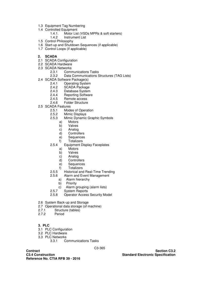
The functional design specification will, as a minimum, cover the following aspects of the software design: a) CONTROL SYSTEM FUNCTIONAL SPECIFICATION TEMPLATE
1. Control System General 1.1 Introduction 1.2 Control System Configuration
Contract Section C3.2 C3.4 Construction Standard Electronic Specification Reference No. CTIA RFB 39 - 2016
C3-365
1.3 Equipment Tag Numbering 1.4 Controlled Equipment
1.4.1. Motor List (VSDs MPRs & soft starters) 1.4.2 Instrument List
1.5 Control Philosophy 1.6 Start-up and Shutdown Sequences (if applicable) 1.7 Control Loops (if applicable)
2. SCADA 2.1 SCADA Configuration 2.2 SCADA Hardware 2.3 SCADA Networks
2.3.1 Communications Tasks 2.3.2 Data Communications Structures (TAG Lists)
2.4 SCADA Software Package(s) 2.4.1 Operating System 2.4.2 SCADA Package 2.4.3 Database System 2.4.4 Reporting Software 2.4.5 Remote access 2.4.6 Folder Structure
2.5 SCADA Features 2.5.1 Modes of Operation 2.5.2 Mimic Displays 2.5.3 Mimic Dynamic Graphic Symbols
a) Motors b) Valves c) Analog d) Controllers e) Sequences f) Totalizers
2.5.4 Equipment Display Faceplates a) Motors b) Valves c) Analog d) Controllers e) Sequences f) Totalizers
2.5.5 Historical and Real-Time Trending 2.5.6 Alarm and Event Management a) Alarm hierarchy b) Priority c) Alarm grouping (alarm lists) 2.5.7 System Reports 2.5.8 Operator Access Security Model
2.6 System Back-up and Storage 2.7 Operational data storage (of machine) 2.7.1 Structure (tables) 2.7.2 Period 3. PLC 3.1 PLC Configuration 3.2 PLC Hardware 3.3 PLC Networks
3.3.1 Communications Tasks

Contract Section C3.2 C3.4 Construction Standard Electronic Specification Reference No. CTIA RFB 39 - 2016
C3-366
3.3.2 Data Communications Structures (TAG Lists) 3.3.3 Communication protocols
3.4 PLC Software General 3.5 PLC Inputs and Outputs 3.6 PLC Software Structure
3.3.1 Modes of Operation 3.3.2 Software Function Blocks / Code Blocks
a) Motors b) Valves c) Analog d) Controllers e) Sequences f) Totalizers
2.3.3 Interlocks (Process and Safety) 2.3.4 Safe Start Warnings
3.7 System Back-up and Storage
APPENDICES SCADA Screen dumps, Displays, Tag lists etc. PLC Code Flowcharts, Code Listings, Logic Diagrams, IO Lists etc.
1.6 Installation The PLCs shall be installed in PLC panels and to be placed adjacent to the new MCCs, in the
associated Switchrooms.
The front half of the PLC panels shall house the PLC, PLC I/O, DC power supplies and a UPS whereas the back half of the panel shall serve as a marshalling panel and shall also house 24 DC / 230 V AC interposing control relays and field instrument supply circuit breakers.
The PLC panel earths shall be bonded to the MCC earth. Cables to and from the PLC panels shall be bottom entry and run in cable trenches below the MCC and PLC panels.
All PLC panel steelwork shall be inspected in the factory after assembly prior to painting and mounting of components and again after mounting of components prior to release to site.
The complete PLC software shall be simulation tested as described in the standard specification before the software is released to site.
2 HUMAN MACHINE INTERFACE
Human Machine Interface (HMI’s) offered shall preferably be 10.4”/VGA touchscreen, 65536 TFT colour with built in Ethernet TCP/IP communications network card. The HMI shall incorporate a PCMCIA slot for extension of memory. The HMI shall be direct connected to the respective PLC and be of type Schneider “Magelis XBT GT” or equivalent and approved. The HMI Development Software shall run on Microsoft Windows 8 or Mac (Macintosh).

Contract Section C3.2 C3.4 Construction Standard Electronic Specification Reference No. CTIA RFB 39 - 2016
C3-367
3 SUPERVISORY CONTROL AND DATA ACQUISITION (SCADA) 3.1 General
The SCADA system shall comprise the latest version of the preferred SCADA package, as this product is fully supported by the client. The Contractor shall derive the full and final Tag list from the free-issued software (if applicable) for existing PLCs and the software for new PLCs to be provided. A complete and adequately commented Tag list shall be provided as part of the O & M Manuals at the start of the SCADA system commissioning.
3.2 SCADA Hardware
a) SCADA Server:
The SCADA server shall be 19" rack mountable industrial computer installed in a Computer Cabinet as described below. The server shall comply to the standard specifications with the following qualifying statements:
Casing 19" rack mountable, 4U
PSU Redundant hot-swappable 300W PSU,
Motherboard and CPU Intel i7 core based system, 3GHz min,
Memory 5GB DDR RAM
Peripherals 19" rack mountable keyboard tray with mini keyboard and mouse
Display Monitor 19" LCD, colour.
Optical Storage CD/DVD re-writer (4GB min)
Data Storage Dual 1000GB SATA Hardrives in Mirror
b) Workstations:
The SCADA operator workstation and view node shall be desktop industrial computers installed in the control room and on a standard office desk in the administration office, as described below. The workstations shall comply to the standard specifications with the following qualifying statements:
Casing Tower
Motherboard and CPU Intel i5 core based system, 2GHz min,
Memory 4GB DDR RAM
Peripherals Desktop keyboard and mouse as specified
Display Monitor 19" LED, colour.
Optical Storage CD/DVD ROM
Data Storage 1TB IDE c) Computer Cabinets:
The SCADA computer cabinet shall be a standard 19" rack mountable cabinet for use in a computer room environment. The cabinet shall conform to the following specification:

Contract Section C3.2 C3.4 Construction Standard Electronic Specification Reference No. CTIA RFB 39 - 2016
C3-368
Cabinet Toughened Aluminium Frame Rack
Door SABS approved toughened glass with lock
Mounting Frame To DIN 41494
The cabinet shall include all peripherals for the mounting of equipment, distribution of power and routing of cables internally and furthermore be adequately ventilated with cooling fans including filters.
d) Control Desks:
The Administration Office desk shall be a conventional office desk. The control desk shall be a steel desk, as per the Detailed Specification. This desk shall
contain the computer and its peripherals, the fibre optic converter to the SCADA network and the associated UPS.
The control desk shall be suitably ventilated with filtered air to dissipate the heat load of the
internal electronic equipment.
e) Uninterruptible Power Supply (UPS)
A UPS shall be provided with the SCADA Server to supply the server and all its peripherals, as well as all operator workstations as required.
The UPS shall conform to the standard specification and following minimum requirements:
Item Description
Manufacturer APC, MGE or approved equivalent
Enclosure 19” Rack Mountable (for Server), Box type for operator workstations
Power Rating 1-2kVA (dependent on offered PC, PLC etc.)
Supply Voltage Single Phase, 230VAC, 50Hz
Power Factor (THD) 0.99 (<5%)
Efficiency >85%
On-Line overload capacity Min 130%
Back-up Time (Internal Battery) 30min (under full load)
Communications Interface Serial or USB
Diagnostic Software Windows based
The UPS shall be supplied with an optional interface for external batteries with which the
back-up time can be extended to 2-3 hours in the event of planned load shedding. 3.3 Server and Workstation Computer Software
All the computers shall be supplied with a valid licensed version of Microsoft Windows 8 professional. A valid licensed version of Norton Anti-Virus shall also be supplied and installed on the computers. The computer's operating systems shall be set up such that they function in their own workgroup environment and the settings below shall be implemented. The naming convention shall be as follows:
Computer name: plant mnemonic+ WS
Contract Section C3.2 C3.4 Construction Standard Electronic Specification Reference No. CTIA RFB 39 - 2016
C3-369
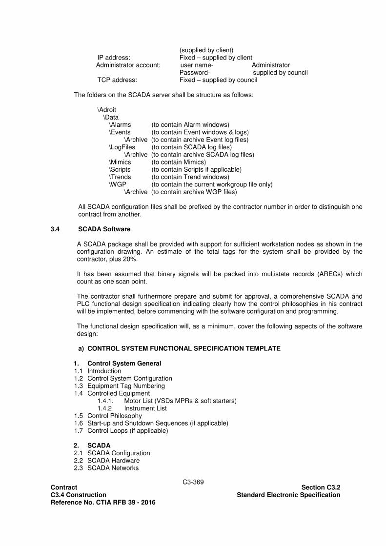
(supplied by client) IP address: Fixed – supplied by client Administrator account: user name- Administrator Password- supplied by council TCP address: Fixed – supplied by council The folders on the SCADA server shall be structure as follows: \Adroit
\Data \Alarms (to contain Alarm windows) \Events (to contain Event windows & logs)
\Archive (to contain archive Event log files) \LogFiles (to contain SCADA log files)
\Archive (to contain archive SCADA log files) \Mimics (to contain Mimics) \Scripts (to contain Scripts if applicable) \Trends (to contain Trend windows) \WGP (to contain the current workgroup file only)
\Archive (to contain archive WGP files)
All SCADA configuration files shall be prefixed by the contractor number in order to distinguish one contract from another.
3.4 SCADA Software
A SCADA package shall be provided with support for sufficient workstation nodes as shown in the configuration drawing. An estimate of the total tags for the system shall be provided by the contractor, plus 20%. It has been assumed that binary signals will be packed into multistate records (ARECs) which count as one scan point. The contractor shall furthermore prepare and submit for approval, a comprehensive SCADA and PLC functional design specification indicating clearly how the control philosophies in his contract will be implemented, before commencing with the software configuration and programming. The functional design specification will, as a minimum, cover the following aspects of the software design: a) CONTROL SYSTEM FUNCTIONAL SPECIFICATION TEMPLATE
1. Control System General 1.1 Introduction 1.2 Control System Configuration 1.3 Equipment Tag Numbering 1.4 Controlled Equipment
1.4.1. Motor List (VSDs MPRs & soft starters) 1.4.2 Instrument List
1.5 Control Philosophy 1.6 Start-up and Shutdown Sequences (if applicable) 1.7 Control Loops (if applicable)
2. SCADA 2.1 SCADA Configuration 2.2 SCADA Hardware 2.3 SCADA Networks

Contract Section C3.2 C3.4 Construction Standard Electronic Specification Reference No. CTIA RFB 39 - 2016
C3-370
2.3.1 Communications Tasks 2.3.2 Data Communications Structures (TAG Lists)
2.4 SCADA Software Package(s) 2.4.1 Operating System 2.4.2 SCADA Package 2.4.3 Database System 2.4.4 Reporting Software 2.4.5 Remote access 2.4.6 Folder Structure
2.5 SCADA Features 2.5.1 Modes of Operation 2.5.2 Mimic Displays 2.5.3 Mimic Dynamic Graphic Symbols
a) Motors b) Valves c) Analog d) Controllers e) Sequences f) Totalizers
2.5.4 Equipment Display Faceplates a) Motors b) Valves c) Analog d) Controllers e) Sequences f) Totalizers
2.5.5 Historical and Real-Time Trending 2.5.6 Alarm and Event Management a) Alarm hierarchy b) Priority c) Alarm grouping (alarm lists) 2.5.7 System Reports 2.5.8 Operator Access Security Model
2.6 System Back-up and Storage 2.7 Operational data storage (of machine) 2.7.1 Structure (tables) 2.7.2 Period 3. PLC 3.1 PLC Configuration 3.2 PLC Hardware 3.3 PLC Networks
3.3.1 Communications Tasks 3.3.2 Data Communications Structures (TAG Lists) 3.3.3 Communication protocols
3.4 PLC Software General 3.5 PLC Inputs and Outputs 3.6 PLC Software Structure
3.3.1 Modes of Operation 3.3.2 Software Function Blocks / Code Blocks
a) Motors b) Valves c) Analog d) Controllers e) Sequences f) Totalizers

Contract Section C3.2 C3.4 Construction Standard Electronic Specification Reference No. CTIA RFB 39 - 2016
C3-371
2.3.3 Interlocks (Process and Safety) 2.3.4 Safe Start Warnings
3.7 System Back-up and Storage APPENDICES SCADA Screen dumps, Displays, Tag lists etc. PLC Code Flowcharts, Code Listings, Logic Diagrams, IO Lists etc.
3.5 SCADA Modes of Operation
The modes of operation to be provided in the SCADA system shall be the following:
Sequence Mode: The SCADA system shall send a start or stop command to the Motor, Valve, Actuator or Controller in the PLC automatically, based on a general group or sequence start command from the SCADA operator. The group or sequence may be programmed in either the SCADA or preferably the PLC and shall always follow the actual process flow, Automatic: The SCADA system shall send a start or stop command to the Motor, Valve, Actuator or Controller in the PLC based on an individual start command by the SCADA operator. The start or stop shall be governed by process flow interlocks. Manual (or Field): The SCADA system shall not send a start or stop command to the Motor, Valve, Actuator or Controller in the PLC as it is controlled by Push Buttons on the MCC or Field Control Box. In this mode, all process flow interlocks are ignored but safety interlocks still apply.
Switching from "Sequence" to "Auto" shall not stop equipment that is already running; however switching any equipment from any state to "Manual" shall stop that equipment and all related equipment via process interlocks. Switching to Manual is provided at the MCC by means of a selector switch.
3.6 SCADA Mimics
SCADA mimics shall be based on the P&ID diagrams provided with this Document and shall as far as possible reflect the flow of material through the works as opposed to mechanical arrangement of the equipment. There shall be an overview mimic, which depicts all functions or processes on the WWTW in block form. Subdivisions of mimics shall furthermore depict areas of the treatment process or operational areas. All mimics shall have a “title” bar at the top of the screen which displays:
• Left; the menu button
• Left of Center, an indication of unacknowledged alarms.
• Center; The name of the mimic, which describes the process area depicted by the mimic.
• Right; Date and Time in the format YYYY/MM/DD HH:MM:SS
Navigation between mimics shall be as follows:
• A system of progressive exposure and hot spots shall be implemented.

Contract Section C3.2 C3.4 Construction Standard Electronic Specification Reference No. CTIA RFB 39 - 2016
C3-372
• On the overview mimic the menu button, once “pressed”, shall pop up a navigation mimic displaying buttons to navigate to all process mimics on the system, general alarms and events.
• On all other mimics, the menu button once “pressed” shall pop up a navigation mimic displaying buttons to navigate to all related mimics and the overview mimic.
• From the navigation pop up mimic “selecting” the desired mimic button shall display a further pop up mimic to select the mimic, related alarm window or one related trend windows.
• On the pop up navigation mimic each mimic button shall indication a current alarm condition for that mimic.
• Where applicable clicking on a device, such as a motor, shall pop up a device "faceplate" displaying relevant data and any control functions associated with the device.
• Hot spots should be available on process mimics to navigate to the upstream or downstream process mimic.
Tenderers shall allow for three re-iterations of graphical displays and mimics during execution of the contract to suite the council and operational personnel’s preferences as well as any process changes that may occur. Faceplates shall be provided as described in the standard specification for all instruments, valves and motors that have control signals or more than one status signal associated with them.
3.7 SCADA Alarms
Alarms shall be provided as described in the standard specification and these shall furthermore be associated with process arrears and applicable mimics. The general alarms window, accessible from the overview mimic, shall only contain alarms NOT displayed in other alarm windows. The Alarm window shall display:
Date (YYYY/MM/DD), Time (HH:MM:SS) 24 hour format, Description (from the agent); Alarm type (from the agent), Reported Data (from the agent).
3.8 SCADA Logging and Trending
Measured Values to be Trended and Recorded (logged) are as listed in the Project Specification. It shall be possible to log data on a rate of change or value deviation only in order to reduce the amount of disk storage required. The measured values to be logged in this manner shall be specified by the client during system commissioning.
Historical Data shall be kept on file for a period of at least three years and disk space as well as back-up storage capacity shall be adequately sized for this purpose. Backup shall be to CD/DVD.
3.9 SCADA Reports
SCADA reports shall be provided as part of an integral function of the SCADA software. The size of the installation does not warrant a separate "Web" based report server. A list of proposed reports to be provided under this contract shall be supplied by council.

Contract Section C3.2 C3.4 Construction Standard Electronic Specification Reference No. CTIA RFB 39 - 2016
C3-373
3.10 SCADA Database
The size of the installation does not warrant a separate database management system and the Adroit native database format may be used for data storage.
3.11 SCADA Security
Secure access to the SCADA server will have been provided as follows: Administrator: An administrator account shall be provided which will allow a person with technical responsibility to gain access to the SCADA system and allow all changes and modifications. Supervisor: A supervisor account shall be provided which will allow a senior plant controller to gain access to the SCADA system and allow operation of the works and setpoint configuration changes. Process Controller: A process controller account shall be provided which will allow the works controllers to gain access to the SCADA system and allow regular shift based operation of the works. All setpoint configuration changes and administrator features shall be disallowed. It shall however be possible to make setpoint configuration changes per individual SCADA item by supplying a higher privilege password than the one currently logged in as. E.g. a process controller may be logged in and operating the works when a setpoint change is required. The Supervisor shall then double click the setpoint item, provide a password, make the change and shall then close the dialog box effective clearing the higher level access. All actions, selections, changes and settings shall be logged for each user during their logged on shift and it shall be possible to draw up selective shift reports per user.
3.12 SCADA Installation, Inspection and Testing
The SCADA Server computer cabinet and SCADA view nodes shall be installed in the specified buildings as per the Detailed Electronic Specification. The SCADA Operator workstation shall be installed as specified in the Detailed Electronic Specification. Power shall be supplied to the cabinet and control desk from the nearest 230VAC distribution board and power cabling shall be run in conduit and power skirting respectively. The computer cabinet and control desk earth shall be bonded to the electrical distribution switchboard earth. SCADA communications cables to and from the computer cabinet and the control desk shall be neatly installed in surface mount PVC power skirting and all entry and exit of cable shall be via PVC lined cable holes to the rear of the cabinet and control desk. The computer cabinet and control desk shall be inspected at the supplier's premises after assembly prior to painting and again after fitting of all components prior to delivery to site. The SCADA configuration shall be inspected and simulation tested as described in the Standard Specification before the software is released to site.

Contract Section C3.2 C3.4 Construction Standard Electronic Specification Reference No. CTIA RFB 39 - 2016
C3-374
4 INTERFACING OF PLCs WITH SWITCHGEAR / CONTROLGEAR AND OTHER ELECTRONIC SYSTEMS
4.1 General
The PLCs shall be interfaced with the following equipment:
• MV, LV switchgear and MCCs
• Field Instruments
• VSDs
• UPSs
• Generator set
• Radio-Frequency Transmitter 4.2 MV, LV switchgear and MCCs
Medium Voltage and Low Voltage switchgear shall be offered and supplied with intelligent interfaces that shall be interfaced to the nearest PLC.
Medium Voltage incoming and feeding circuit breakers shall be interfaced via either a serial "Fieldbus" interface or discrete IO to the Intake Substation PLC.
Low Voltage incoming circuit breakers shall be interfaced via either a serial "Fieldbus" interface or discrete IO to the relevant process PLC.
Signals to be communicated from the switchgear shall include as a minimum:
o Open o Closed o Tripped o Current o Voltage o Other (e.g. phase imbalance etc.)
All LV motor starters shall utilize intelligent motor management devices which shall interface to the PLC via an field bus. Signals to be communicated from each starter shall include as a minimum:
• Available/ Healthy
• Start
• Stop
• Running
• Tripped
• E-Stop 4.3 Field Instrumentation
All instrumentation shall be interfaced to the PLC via intelligent communications interfaces or conventional analog current loops.
Power supply to instruments shall be either 230VAC UPS power or 24VDC loop powered. Separate terminals with breakers shall be provided in the marshalling panel for this purpose.
The preferred "Fieldbus" Interfaces shall be "Interbus", "Profibus", "ASI" or approved equivalents. It is envisaged that Interbus or Profibus be used on instrumentation associated with the

Contract Section C3.2 C3.4 Construction Standard Electronic Specification Reference No. CTIA RFB 39 - 2016
C3-375
bioreactors, UV disinfection and final effluent pump station and the ASI bus be used with the dewatering machines and the inlet works.
4.4 Variable Speed Drives (VSDs)
VSDs shall be connected to the PLC via serial communications for advanced monitoring purposes
only. The following information shall be the minimum communicated to the SCADA via the PLC for
logging and display:
• Motor supply voltage and current
• Motor load (%)
• Motor speed (rpm)
• Motor hours run
• Number of starts
• Number of trips
• Protection alarms and trips.
The communications protocol shall suit the VSDs and PLCs offered without the need for extensive programming. Consideration shall also be given to the use of the above mentioned Fieldbus interfaces in order to standardize on the installation.
4.5 Uninterruptable Power Supplies (UPSs) UPSs shall be connected to the PLCs via serial communications for monitoring purposes only. 4.6 Generator Set Controllers New generator controllers shall be connected to the closest PLC via RS232/RS485
communications interface for monitoring purposes only. 4.7 Radio Frequency Transmitter & Receiver A radio frequency transmitter shall be installed as per the Detailed Electronic Specification. The
transmitter shall be connected to the associated PLC/RTU via serial communications interface. The RTU unit shall be of type Motorola Moscad RTU or equal and approved. The receiver shall be installed at the main server position and connected to the SCADA system for
monitoring purposes only. 5 POWER, CONTROL AND INSTRUMENTATION CABLES & WIRING All general wiring shall be multi-stranded of minimum cross-sectional area of 1mm² with colour-fast
PVC insulation. All cables shall be supplied in quantities which allow for a reasonable amount of wastage. All cabling shall be arranged for maximum accessibility and shall allow for equipment removal
without disturbing other operating equipment or disfiguring wiring. Installed cabling shall not obstruct vision or access to any other equipment. No cabling shall be installed directly in concrete or brickwork.

Contract Section C3.2 C3.4 Construction Standard Electronic Specification Reference No. CTIA RFB 39 - 2016
C3-376
Only armoured cables may be buried directly in the ground.
Cables within buildings are to be carried on overhead cable trays attached to the building frame or other supports or on cable trays in trenches or under suspended floors.
When laying cables great care shall be taken to avoid twisting, kinking, excessive tension,
mechanical pressure and sharp bending. Cables shall run parallel. Only the use of approved lubricants to assist in the drawing in of cable into conduit shall be
permitted. At all cable ends compression gland fittings shall be used. Slotted cable trunking shall be used inside cabinets wherever possible. Wire bundle runs in consoles, etc., shall be bound with nylon cable ties at intervals not exceeding
five bundle diameters. Bundles shall have uniform appearance, circular cross sections, and shall be securely fastened to
the panel framework. 5.1 Instrumentation Cables (24V / 220V)
Instrumentation cable shall be constructed of multiple twisted pairs of insulated stranded copper wire, PVC insulated with an overall aluminium shield, extruded PVC inner jacket, served with steel wire armour with an extruded PVC outer jacket. The nominal conductor resistance shall not exceed 3,5Ω per 100 m at 20ºC. The complete cable shall withstand a dielectric test conductor to conductor and conductor to shield of 1000V dc for one minute. The insulation resistance of each conductor shall be not less than 8800 mΩ/km for 1 minute at 500V and 20oC, measured with the remaining conductors in the cable connected to the armouring. The minimum core size shall be 1,5mm². All instrumentation and signal cables (excluding optical fibre cables) shall be installed separate from power cables.
5.2 Panel Wiring (24V / 220V)
Further to the abovementioned Clause, all panel wiring shall be of the silicone-insulated type with stranded tinned copper conductors, with a minimum conductor size of 1mm ².
The colour of the conductors shall be as follows:
220V AC control Line => Brown
220V AC Neutral => Black
+24V DC => Orange

Contract Section C3.2 C3.4 Construction Standard Electronic Specification Reference No. CTIA RFB 39 - 2016
C3-377
-24V DC => Violet or Purple
5.3 PLC Wiring
Further to the abovementioned Clause, all panel wiring shall be of the silicone-insulated type with stranded tinned copper conductors, with a minimum conductor size of 1mm ².
The colour of the conductors shall be as follows for Digital Signals: PLC DIGITAL Inputs => Grey PLC DIGITAL Outputs => Pink
The colour of the conductors shall be as follows for Analogue Signals:
PLC ANALOGUE Inputs => twisted pair Red/black PLC ANALOGUE Outputs => twisted pair White/black 5.4 Spare Cores in all Cables
All cables installed shall include for spare cores. The spare cores shall amount to 10% of the number of cores used, rounded up to the nearest whole core.
5.5 Cable Identification
A suitable tag, onto which the appropriate cable identification number in accordance with the Contractor’s detailed cable schedule shall be stamped, shall be adequately secured just below the gland at the ends of each cable. Where cables deviate from one route to another (e.g. at tee’s, on cable trays or in trenches) additional identification tags with numbers shall be fitted to each cable, within 500mm of the point of deviation.
5.6 Cable Schedules
The Contractor shall submit to the Engineer a detailed schedule of all cables together with drawings showing cable routes (both underground and on cable trays) for approval prior to the commencement of laying such cables.
5.7 Cable and Wire Termination and Mounting Hardware Every terminal strip shall be numbered or named. Every terminal shall be numbered. Cable glands shall be of the compression ferrule type with "O" ring seals. No joints will be allowed in cables or wires between terminations. All cable cores and wires shall be numbered at all termination points with "slip-on" interlocking type
cable markers. Split-ferrule types are unacceptable. In the case of multicore cables each core shall be numbered.
Wherever possible, terminations of cable cores and wires shall be made using spade, pin or
bootlace ferrule type crimp-on lugs.

Contract Section C3.2 C3.4 Construction Standard Electronic Specification Reference No. CTIA RFB 39 - 2016
C3-378
Lugs may only be crimped with controlled pressure crimping tools of the correct size for the lug used.
Thin, collapsing pipe type ferrules shall not be used. High quality wire strippers shall always be used, and care taken not to nick or otherwise damage
the strands. Terminals shall be located so that all connections can be made easily. When wiring of different potentials and types of supply use the same terminal rail then a clear
space, or a barrier shall be provided between terminal blocks. Metal wireways shall be electrically continuous. Cable and wireways supports shall be spaced adequately to avoid sagging between supports.
Cable trays and wireways shall be firmly fastened to such supports. Any bending, jagged edges or any other forms of damage or deformation of cable trays or
wireways shall be made good, before cables are installed. Conduit shall be thoroughly cleaned and have all burrs removed before the drawing in of any cable. Where outlet boxes, draw boxes, etc., are to be mounted in highly visible areas special attention
shall be given to their aesthetic appearance. Cable routes shall be chosen to avoid high temperatures and other hazards. All main cable routes must be vermin-proofed. Where trays are joined together, galvanized or cadmium plated bolts and nuts are to be used.
Welding is not permitted. The tray shall be supported at every change in direction of the cable tray route. The minimum
radius of any bend of the tray is to suit the minimum bending radius of the largest cable on the tray. Cable trays shall be firmly secured in position in such a manner to cause as little obstruction to
walkways etc., as possible.
Hangers, supports and anchors for wireways and equipment, shall be designed and installed with regard to appearance and convenience as well as for adequate strength and rigidity. Only professional quality fixing material and methods shall be used. Nails and glue are not acceptable.
6 OPTICAL FIBER CABLE
The optical fibres shall comply with SANS IEC 60793 and the optical fibre cables shall comply with SANS IEC 60794 and shall be installed in accordance with SANS IEC 60794-1-1. All cables or cable lengths shall be supplied along with Factory Test Certificates. Cable ends shall be suitably made off / protected to avoid water ingress, damage etc., and while in storage. The cables shall be of the multimode type, suitable for direct burial in the ground. A cable shall contain 12 fibres packaged in two tubes and the fibres shall be to the following specification:

Contract Section C3.2 C3.4 Construction Standard Electronic Specification Reference No. CTIA RFB 39 - 2016
C3-379
• core diameter : 50 microns
• cladding diameter : 125 microns
• primary acrylic buffer : 250 microns diameter
• category : A2
• wavelength : 850nm
• attenuation : 3dB/km maximum
• bandwidth : 400-600 MHz/km
The cables shall be constructed to the following specification:
• tubes shall not be filled with water blocking compound
• the cable core shall be filled with water blocking compound
• the cable shall be designed with sufficient strength members to meet installation and service conditions so that the fibres are not subjected to strain of more than the limits specified by the manufacturer
• a moisture barrier shall be provided by a metallic tape applied over the cable core with a longitudinal overlap and bonded to the sheath
• the inner sheath shall be made of polyethylene
• the cable shall be armoured with Corrugated Steel Tape (CST)
• the outer sheath shall be a seamless sheath made of UV-stabilizer weather-resistant polyethylene in accordance with Clause 22 of SANS IEC 60708-1
• the outer sheath shall be marked with the manufacturer’s name and “Optical Fibre Cable” as a single line of marking at intervals not exceeding 1000mm
• Optical elements and each fibre with a cable element shall be uniquely identified by colours.
Cables shall be subjected to the following tests in accordance with SANS IEC 60794-1-2:
• tensile performance
• cable bend
• crush
• temperature cycling
• water penetration
In addition, compatibility with the particular installation conditions shall be demonstrated though the following tests:
• impact
• kink
• torsion
• sheath abrasion resistance
6.1 Pigtails The pigtails need to have the following specifications:
Feature Value
Specification 10-/125
Length 1m
Mode Unjacketed
Insertion loss <=0.3 dB
Return Loss >= 45 dB
Durability <= 0.1 dB

Contract Section C3.2 C3.4 Construction Standard Electronic Specification Reference No. CTIA RFB 39 - 2016
C3-380
6.2 Co-ax / Fibre converters
Supply and install co-ax to fibre and fibre to co-ax media at the locations specified. These modules will be used to convert the video signal from the camera to a fibre medium for transmission to the station. The contractor can choose to specify a camera with a fibre backbone provided there are no protocol constraints being imposed by the conversion. The fibre will need to be converted back to co-ax at the station.
6.3 Fibre Patch Panel
• The Fibre Patch panel needs to be complete with Glands, Fibre Optic Management Kit, Brush and Blank Panels
• These panels shall have the capacity to be used for a combination of splicing and termination of fibre optic cable or outside plant (OSP) cables.
• Labels shall be provided for identifying fibre splices and terminations. 7 FIELD INSTRUMENTATION 7.1 General
Field instrumentation shall be provided in accordance with the process flow diagrams and the Field Instrumentation list.
The instruments shall conform to the standard specifications and the following qualifying statements.
Field instrumentation shall be connected to the PLCs to provide the required monitoring and control specified in the Control Philosophy. Where the latter calls for local / remote indication, it shall be interpreted as follows:
o local indication : display on the field instrument's transmitter. o remote indication : signal to be input to PLC for indication on SCADA.
All field instrumentation shall be supplied together with and installed in a stainless steel enclosure with glass window as indicated on the tender drawings.
All field instrumentation and/or electronic equipment installed within a MCC shall be protected against surges caused by lightning strikes, by means of surge arrestors/line protector modules connected to the signal and communication cables installed in the field.
7.2 Turbidity Analyser
Turbidity in the sludge being pumped to the dewatering facility shall be determined by nephelometry, i.e. the scatter of incident light by particles in the water. The turbidity meters shall conform to the following qualifications:
Design
The Turbidity Analyser shall be supplied with standard NPT connections for sample ingress, egress and drain, suitably sized and placed to reduce the formation of bubbles. The complete analyser shall be accommodated in a single housing. Signal output of 4 to 20mA shall represent a turbidity of 0 to 9999 NTUs, or any standard range up to 9999 NTU. This range shall be determined by the application, e.g.: clean water or dirty water.

Contract Section C3.2 C3.4 Construction Standard Electronic Specification Reference No. CTIA RFB 39 - 2016
C3-381
The calibration media shall be supplied by the vendor of the analyser. The calibration media shall be formazin, accurately diluted to the required strength. Note that NTU = FTU, or Nephelometric Turbidity Units = Formazin Turbidity Units. Glass standards, as supplied by the vendor, are permissible.
Performance
Accuracy : ± 2% (0-50 NTU)
± 5% (0-2000 NTU) ± 10%(0-9999 NTU)
Resolution : ± 1% Repeatability : ± 1%
Preferred : Hach Gimat, Klever, Endress + Hauser 7.3 Ultrasonic Level Sensors
a) General Ultrasonic level measurement shall be by means of sensors (transducer) and separate transmitter,
with the sensors powered via the transmitter. The sensors shall be mounted on suitably-sized brackets of glass-fibre reinforced construction, stainless steel or similar non-corroding material directly over the medium being monitored.
The sensor shall furthermore be equipped with an integral cable long enough to reach the
transmitter, with the complete unit IP68 rated.
The transmitter shall be of minimum IP65 rating and housed in a 316L protective enclosure
providing the same rating. The transmitters shall have a local LCD display, which shall be visible with the protective housing closed. The enclosures shall be installed against a building wall or a separate 316L stand specifically provided for this purpose.
The units shall conform to the specification listed in “Ultrasonic Flow Meters” of this document, and
with the following qualifications: Power supply : 24V DC Output : 4-20mA analog signals (x2), 2x digital b) Differential Level measurement over inlet channels
Two ultrasonic sensors with a common transmitter shall be mounted over the inlet channel for control of the screen.
The sensors shall be mounted one upstream and one downstream of the screen on suitable brackets manufactured from either 304 Stainless Steel or glass reinforced polyester.
Medium Raw Sewage
Measuring Range 0 – 5m
Outputs 4-20mA (x2); 2x digital
7.4 Level Floats
The float switches shall be a rod operated unit with a float rising and falling according to the liquid level. The rod shall be fitted with adjustable collars between which the float operates. The top of the rod shall be anchored to a pivot pin in the end of a counter balanced rocker arm supported on a spindle. The end of the spindle shall actuate a glass encapsulated mercury switch enclosed in

Contract Section C3.2 C3.4 Construction Standard Electronic Specification Reference No. CTIA RFB 39 - 2016
C3-382
cast aluminium housing. Before the Contractor purchases or installs the float switch, it shall be approved by the Engineer in the position as depicted on the drawings. The cast aluminium housing of the switch shall be mounted on a robust hot dipped galvanised mild steel bracket fixed to the metal framework supporting the surface-mounted connection box, directly above the deepest part of the sump and adjacent to the terminal box. The bracket shall be designed to permit the float to move up and down on the rod without touching the metal framework.
7.5 Ultrasonic Flow Meters Ultrasonic Flow measurement shall be by means of a sensor (transducer) and separate
transmitter, with the sensor powered via the transmitter. The sensors shall be mounted on suitably-sized brackets of glass-fibre reinforced construction, stainless steel or similar non-corroding material directly over the medium being monitored.
The sensor shall furthermore be equipped with an integral cable long enough to reach the
transmitter, with the complete unit IP68 rated.
The transmitter shall be of minimum IP65 rating and housed in a 316L protective enclosure
providing the same rating. The transmitter shall have a local LCD display, which shall be visible with the protective housing closed. The enclosures shall be installed against a building wall or a separate 316L stand specifically provided for this purpose.
The unit shall conform to the standard specification with the following qualifications:
a) Transducers
This section covers ultrasonic transducers located above the surface of the water, at the measuring point. Suitable support brackets shall be supplied for the ultrasonic transducers. Design: Enclosure : IP65 Membrane : Stainless Steel Electrical Connection : 20mm ISO conduit Max Operating Temperature : 60°C
b) Transmitter Preference shall be given to a unit that is "smart" in that calibration and diagnostic checking shall be by hand-held calibrator. The ability of the system to be configured to ignore unwanted signals from obstructions is essential. Design Enclosure : To suit application
Output : 4-20mA into 250Ω load, pulse, 1x digital Power Supply : 24V DC Calibration Adjustments : Independent for Zero & span

Contract Section C3.2 C3.4 Construction Standard Electronic Specification Reference No. CTIA RFB 39 - 2016
C3-383
Performance Accuracy : 1% of span or better Repeatability : 0,2% of span Dead Band : <0,2% of span Ambient Temperature Effect : <0,5% of maximum span per 10°C change Preferred : Endress + Hauser, Milltronics
The Transmitters and Transducers shall be installed as indicated on the general arrangement
drawings included and shall be cabled to the PLC control panel via separate shielded twisted pair instrumentation cables. Power supply and Totalizing Signals shall be connected via separate multi-core core power and control cables.
7.6 Flow switches Flow switches shall be provided to monitor flow on various pipelines. The switches shall operate on a thermal principal and conform to the following specification for
Thermal Flow Switches:
Wetted pants ; Stainless Steel Process Connection : 1" N.P.T. or to suit Electrical Connection : 20 mm ISO conduit Max Process Pressure : 1000 kPa Max process Temperature : 100°C Preferred : Effector FCI
The flow switches shall consist of fully integrated sensor and transmitter units with a minimum IP65
rating. The flow switch shall be connected to the PLC by means of a potential-free contact.
7.7 Pressure Transmitters
Pressure transmitters shall be provided for the measuring and control of pressure on the relevant lines.
Pressure sensing shall be by means of capacitive diaphragm principal and a completely integrated instrument (sensor and transmitter) shall be provided in accordance with this specification.
The instrument shall be flange mounted and shall include an isolation valve as described in Section A.
A minimum of IP65 rating shall be provided and the instrument shall include a "head mount" LCD display indicating the current measured pressure.
The unit shall conform to the standard specification with the following qualifications: Design
Element Type : Diaphragm Wetted parts : 316 Stainless Steel Body material : 316 Stainless Steel Element Type : Diaphragm Wetted Parts : 316 Stainless Steel

Contract Section C3.2 C3.4 Construction Standard Electronic Specification Reference No. CTIA RFB 39 - 2016
C3-384
Body material : 316 Stainless Steel Process Connection : ½" NPT Electrical Connection : 20mm ISO conduit Electronics Housing Protection : IP65 Overpressure Limit : 200% of maximum process static pressure
Mounting : Pipestand or direct process connection as
appropriate to application
Output : 4-20 mA into 250Ω load Supply : 24 V DC nominal Calibration Adjustments : Independent Zero and span Element Temperature Limitation : 100° C Electronics : 70° C Humidity Limits : 0 - 100% relative humidity
Performance
Accuracy : 0.5% of span or better Repeatability : 0.1% of span Dead Band : not to exceed 0.1% of span Ambient Temperature Effect : not to exceed 0.5% of maximum span/10°C
change
Preferred type : Endress + Hauser, Honeywell Smart
7.8 Pressure switches Pressure switches shall be provided to monitor pressure on the relevant lines. Pressure sensing shall operate on a diaphragm type principal and the instrument shall conform to
the following specification for Pressure Switches.
Element Material : Bronze or Stainless Steel to suit the application Process Connection : ½" N.P.T. or to suit Electrical Connection : 20 mm ISO conduit Max Process Pressure : 5000 kPa Max Process Temperature : 100°C
Preferred : Asco
The pressure switches shall consist of fully integrated sensor and transmitter units with a minimum
IP65 rating. The switch shall be connected to the PLC by means of a potential-free contact. 7.9 Proximity Switches All valves shall be monitored preferably via inductive proximity switches. Where actuated valves
are offered with integrated limit switches, these will be deemed acceptable as long as they are adequately protected against the harsh conditions of the site.
Proximity switches shall be encapsulated and shall operate on a magnetic field principle. The switch shall have a LED indicator and have a detection range of 10 - 20mm. Proximity switches shall have a mechanical adjustment on the mounting bracket of at least 35 mm.
Preferred : Turck

Contract Section C3.2 C3.4 Construction Standard Electronic Specification Reference No. CTIA RFB 39 - 2016
C3-385
The proximity switches shall be supplied with integral cables all to an IP68 Rating. Individual switches shall then be wired to the PLC.
7.10 Solenoid Valves Electrically actuated solenoid valves shall be provided as set out in the Detailed Project
Specification. Solenoid Valves shall be provided with a minimum of IP67 rating and shall be preferably from
Festo, Burkett or approved equivalent manufacturers. Solenoid valves shall be equipped with integrated limit switches to provide “open” and “close” signals to the PLC and SCADA system.
The solenoids shall be connected to the PLC via conventional control cabling. 7.11 Alarms
An audible and visual alarm shall be installed at all buildings on site. The alarm units shall be mounted on the outside wall at the entrance to the building and in a
location visible from the control room and administration offices.
The alarm unit shall be controllable by the PLC.
The audible sirens to be supplied shall conform to the following specifications:
Weatherproof Motor Driven Siren
Audibility 110dB @ 1m (minimum)
Frequency 1500Hz
Voltage 220Vac / 24Vdc
Rating 15min on / 10min off (adjustable)
Construction/Finish Cast Aluminium / Black
Protection IP65
The visual strobes to be supplied shall conform to the following specifications:
Weatherproof Xenon Strobe (Beacon)
Colour Red
Operation Flashing (“Double Flash” option)
Voltage 220Vac / 24Vdc
Construction Polycarbonate Lens, ABS body and base
Protection IP65
8 UNINTERRUPTABLE POWER SUPPLIES 8.1 General
A UPS shall be provided for each separate piece of equipment such as a SCADA computer or a PLC. Specific requirements are as detailed in the Project Specification. The UPS shall include an alarm panel, serial connection to a SCADA server and adequate batteries for 30-min backup.

Contract Section C3.2 C3.4 Construction Standard Electronic Specification Reference No. CTIA RFB 39 - 2016
C3-386
8.2 UPS Specification
The UPS’s shall be to the “Aros” Catalogue model Sentinel XR, comply with the following specification for high availability, high stability under varying supply and varying loads, or equivalent.
(a) Rated input voltage: 230 V (+/-15%) at 50 Hz (+/-5%) single phase (Without
having to supply a CVT line conditioner).
(b) Rated output voltage: 230 V (+/-1,5%) at 50 Hz, single phase.
(c) Inverter rating: -Dynamic regulation at 100% load application/removal Transient Recovery - +/-5% recovering to 1% within 10msec.
LOSS of AC supply: -No change. Total harmonic distortion: -Better than 3% (Linear load). Overload capacity: -120% (10 seconds).
(d) Power rating: Sufficient to power all equipment as specified including PLCs as well as the PLC Data Network equipment and fibre optic transceivers.
(e) Rated stored: Standard with 30 minutes range energy time
(f) Interfaces: SCADA: Microprocessor serial interface (SNMP) and
LCD Status display.
(g) Preferred Equipment: Aros Sentinal XR Online, double conversion Batteries for UPS to be 10 year long life units 8.3 Installation
UPS output shall be cabled to equipment to which it shall be supply. If Plug Socket Outlets are required, these shall be 15A red top plugs (dedicated).
9 RADIO, TELEVISION, COMPUTER AND COMPUTER SYSTEM INTERFERENCE
The Contractor shall allow for interference suppression components where required, to ensure that the electrical installation shall not cause interference to radio, television, staff location, computer and computer systems.
10 OPERATION AND MAINTENANCE MANUALS
Operation and Maintenance (O & M) manuals are required for all major items of equipment. Where literature is supplied by the manufacturer, the Contractor shall omit all duplicate sections in other languages. The manual shall be in English only.
These O & M manuals are required for the commissioning of the works. The installation shall not be commissioned or the Subcontract deemed complete without these manuals. The Contractor shall provide all electrical drawings on "CD" in a format capable of being retrieved directly into AutoCAD 2012.

Contract Section C3.2 C3.4 Construction Standard Electronic Specification Reference No. CTIA RFB 39 - 2016
C3-387
The Contractor shall supply an “As Built” cable schedule included in the electrical portion of the maintenance manual. Equipment lists shall be provided with each drawing. Specific requirements for the manual, layout and format etc., shall be supplied as detailed in the Project Specification.