
Section A - cable railing
16
Ultra-tec Cable Railing Systems A-1 SECTION A DERIVATION OF EQUATIONS FOR CODE REQUIRED INTERMEDIATE RAILING SPHERE PASS-THROUGH RESISTANCE A.1—EFFECTIVE MODULUS OF ELASTICITY FOR WIRE ROPE CABLE The modulus of elasticity for Type-316 Stainless Steel is: E 28000 ksi ⋅ := However, the effective modulus of elasticity for wire rope is less than the nominal material modulus of elasticity because of the twist in the wire rope strands. With the rope twist, the individual wire strands are longer than the actual cable length, thus for a given stress, strain will be greater in the cable than in a solid round bar of equal area. This increase in strain for a given load appears as a lower "effective" modulus of elasticity. For ease of use, this effective modulus is calculated based on the nominal cable area, rather than actual steel area, to make calculations involving cable diameter simpler. Symbols and Notations ε Strain, in/in. σ Stress, ksi (ksi = 1000 psi). A Cross-sectional area, in 2 . D Diameter of wire rope cable, in. E Modulus of Elasticity , ksi. E eff Effective Modulus of Elasticity, ksi . G Cable stretch factor, determined by wire rope manufacturer. W Load in cable, lbf. Objective Given the value for G , determine the effective modulus of elasticity, E eff . Stress and Strain The basic stress-strain relationship for a material, througout the linear-elastic range, is given by: ε σ E = (1) Stress is defined as the force (load) divided by the area: σ W A = (2) Area for a circular cross-section of diameter, D , is given by: A π D 2 ⋅ 4 = (3) Combining Eqns (1), (2) and (3) produces this equation for strain, given a force, P : ε 4 W ⋅ π D 2 ⋅ E ⋅ = (4) Copyright © 2003-2008, Ultra-tec Corporation, Carson City, Nevada. All rights reserved.
Transcript of Section A - cable railing
7/21/2019 Section A - cable railing
http://slidepdf.com/reader/full/section-a-cable-railing 1/16
Ultra-tec Cable Railing Systems A-1
SECTION A
DERIVATION OF EQUATIONS FOR CODE REQUIREDINTERMEDIATE RAILING SPHERE PASS-THROUGH RESISTANCE
A.1—EFFECTIVE MODULUS OF ELASTICITY FOR WIRE ROPE CABLE
The modulus of elasticity for Type-316 Stainless Steel is:
E 28000 ksi⋅:=
However, the effective modulus of elasticity for wire rope is less than the nominal material modulus of
elasticity because of the twist in the wire rope strands. With the rope twist, the individual wire strands are
longer than the actual cable length, thus for a given stress, strain will be greater in the cable than in a solid
round bar of equal area. This increase in strain for a given load appears as a lower "effective" modulus of
elasticity. For ease of use, this effective modulus is calculated based on the nominal cable area, rather than
actual steel area, to make calculations involving cable diameter simpler.
Symbols and Notations
ε Strain, in/in.
σ Stress, ksi (ksi = 1000 psi).
A Cross-sectional area, in2.
D Diameter of wire rope cable, in.
E Modulus of Elasticity, ksi.
Eeff Effective Modulus of Elasticity, ksi.
G Cable stretch factor, determined by wire rope manufacturer.
W Load in cable, lbf.
Objective
Given the value for G , determine the effective modulus of elasticity, E eff .
Stress and Strain
The basic stress-strain relationship for a material, througout the linear-elastic range, is given by:
ε σ
E= (1)
Stress is defined as the force (load) divided by the area:
σ W
A
= (2)
Area for a circular cross-section of diameter, D , is given by:
Aπ D
2⋅
4= (3)
Combining Eqns (1), (2) and (3) produces this equation for strain, given a force, P :
ε 4 W⋅
π D2
⋅ E⋅
= (4)
Copyright © 2003-2008, Ultra-tec Corporation, Carson City, Nevada. All rights reserved.
7/21/2019 Section A - cable railing
http://slidepdf.com/reader/full/section-a-cable-railing 2/16
Ultra-tec Cable Railing Systems A-2
Stretch in a Wire Rope
The stretch in a wire rope under load has been quantified emperically,and follows the equation:
ε W
D2
G
100in
2
lbf ⋅
⋅= (5)
The value of G varies according to strand geometry and cable material. For stainless steel 1x19 wire rope:
G 7.79 10 6−
⋅:=
Effective Modulus of Elasticity
Since the strain from each of Eqns. (4) and (5) must be the same, we can set the two equations equal to each
other and solve for the effective modulus of elasticity:
4 P⋅
π D
2
⋅ Eeff ⋅
P
D
2
G
100 in
2
lbf ⋅
⋅=
Eeff
400 lbf ⋅
π G⋅ in2
⋅
:= Eeff 16345ksi=
Effective Modulus of
Elasticity for
316 Stainless Steel
1x19 Wire Rope:
Eeff 16300 ksi⋅:=
Copyright © 2003-2008, Ultra-tec Corporation, Carson City, Nevada. All rights reserved.
7/21/2019 Section A - cable railing
http://slidepdf.com/reader/full/section-a-cable-railing 3/16
Ultra-tec Cable Railing Systems A-3
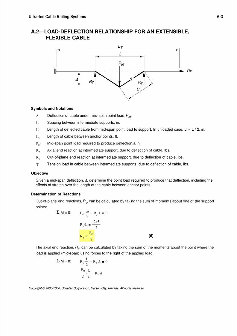
A.2—LOAD-DEFLECTION RELATIONSHIP FOR AN EXTENSIBLE, FLEXIBLE CABLE
Symbols and Notations
∆ Deflection of cable under mid-span point load, P ef
.
L Spacing between intermediate supports, in.
L' Length of deflected cable from mid-span point load to support. In unloaded case, L' = L / 2, in.
LT Length of cable between anchor points, ft.
Pef Mid-span point load required to produce deflection ∆, in.
Rx Axial end reaction at intermediate support, due to deflection of cable, lbs.
Ry Out-of-plane end reaction at intermediate support, due to deflection of cable, lbs.
T Tension load in cable between intermediate supports, due to deflection of cable, lbs.
Objective
Given a mid-span deflection, ∆, determine the point load required to produce that deflection, including the
effects of stretch over the length of the cable between anchor points.
Determination of Reactions
Out-of-plane end reactions, R y , can be calculated by taking the sum of moments about one of the support
points:
Σ M = 0: Pef
L
2⋅ Ry L⋅− 0=
Ry L⋅Pef L⋅
2=
Ry
Pef
2= (6)
The axial end reaction, R x , can be calculated by taking the sum of the moments about the point where the
load is applied (mid-span) using forces to the right of the applied load:
Σ M = 0: Ry
L
2⋅ Rx ∆⋅− 0=
Pef
2
L
2⋅ Rx ∆⋅=
Copyright © 2003-2008, Ultra-tec Corporation, Carson City, Nevada. All rights reserved.
7/21/2019 Section A - cable railing
http://slidepdf.com/reader/full/section-a-cable-railing 4/16
Ultra-tec Cable Railing Systems A-4
Rx
Pef L⋅
4 ∆⋅= (7)
Knowing the two end reactions, the tension in the cable may be resolved using the Pythagorean Theorum:
T Ry
2
Rx
2
+=
TPef
2
2Pef L⋅
4 ∆⋅
2
+=
T1
∆
Pef 2
4∆
2⋅
Pef 2
4
L2
4 ∆2
⋅
⋅ ∆2
⋅+⋅=
TPef
2 ∆⋅∆
2 L2
4+⋅= (8)
Strain Compatibility
The elongated (stretched) length of the cable under load can be found directly from the geometry, using the
Pythagorean Theorum:
L' ∆2 L
2
2
+= ∆2 L
2
4+=
where L' (the hypotenuse) represents one-half of the total elongated length.
The elongation (change in length) in the cable is given by:
δ 2 L'⋅ L−=
δ 2 ∆2 L
2
4+⋅ L−= (9)
This total elongation is a result of cable stretch over two distinct regions: the region between the intermediate
supports where the cable is loaded and where defelection in the cable is occuring, and the region beyond the
intermediate supports where the cable is being stretched due to the tension from the axial reaction.
δ T L⋅
E A⋅
Rx LT L−( )⋅
E A⋅+=
Substituting Eqns. (7) and (8) and simplifying yields:
δ
Pef
2 ∆⋅∆
2 L2
4+⋅
L⋅
E A⋅
Pef L⋅
4 ∆⋅
LT L−( )⋅
E A⋅+=
δPef L⋅
2 ∆⋅ E⋅ A⋅∆
2 L2
4+⋅
Pef L⋅
2 ∆⋅ E⋅ A⋅
LT L−
2
⋅+=
δPef L⋅
2 ∆⋅ E⋅ A⋅∆
2 L2
4+
LT L−
2+
⋅= (10)
Copyright © 2003-2008, Ultra-tec Corporation, Carson City, Nevada. All rights reserved.
7/21/2019 Section A - cable railing
http://slidepdf.com/reader/full/section-a-cable-railing 5/16
Ultra-tec Cable Railing Systems A-5
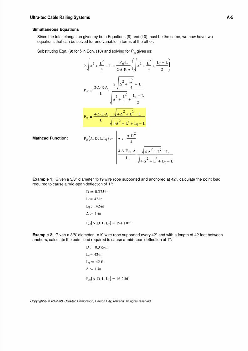
Simultaneous Equations
Since the total elongation given by both Equations (9) and (10) must be the same, we now have two
equations that can be solved for one variable in terms of the other.
Substituting Eqn. (9) for δ in Eqn. (10) and solving for P ef gives us:
2 ∆2 L2
4+⋅ L−
Pef L⋅
2 ∆⋅ E⋅ A⋅∆
2 L2
4+
LT L−
2+
⋅=
Pef
2 ∆⋅ E⋅ A⋅
L
2 ∆2 L
2
4+⋅ L−
∆2 L
2
4+
LT L−
2+
⋅=
Pef
4 ∆⋅ E⋅ A⋅
L
4 ∆2
⋅ L2
+ L−
4 ∆2
⋅ L2+ LT+ L−
⋅=
Mathcad Function: Pef ∆ D, L, LT,( ) Aπ D
2⋅
4←
4 ∆⋅ Eeff ⋅ A⋅
L
4 ∆2
⋅ L2
+ L−
4 ∆2
⋅ L2
+ LT+ L−
⋅
:=
Example 1: Given a 3/8" diameter 1x19 wire rope supported and anchored at 42", calculate the point load
required to cause a mid-span deflection of 1":
D 0.375 in⋅:=
L 42 in⋅:=
LT 42 in⋅:=
∆ 1 in⋅:=
Pef ∆ D, L, LT,( ) 194.1 lbf =
Example 2: Given a 3/8" diameter 1x19 wire rope supported every 42" and with a length of 42 feet between
anchors, calculate the point load required to cause a mid-span deflection of 1":
D 0.375 in⋅:=
L 42 in⋅:=
LT 42 ft⋅:=
∆ 1 in⋅:=
Pef ∆ D, L, LT,( ) 16.2lbf =
Copyright © 2003-2008, Ultra-tec Corporation, Carson City, Nevada. All rights reserved.
7/21/2019 Section A - cable railing
http://slidepdf.com/reader/full/section-a-cable-railing 6/16
Ultra-tec Cable Railing Systems A-6
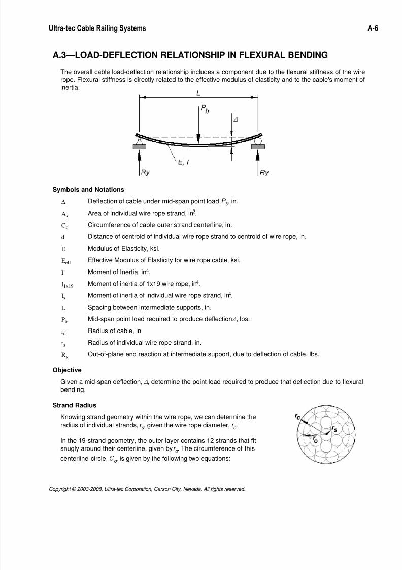
A.3—LOAD-DEFLECTION RELATIONSHIP IN FLEXURAL BENDING
The overall cable load-deflection relationship includes a component due to the flexural stiffness of the wire
rope. Flexural stiffness is directly related to the effective modulus of elasticity and to the cable's moment of
inertia.
Symbols and Notations
∆ Deflection of cable under mid-span point load, P b , in.
As Area of individual wire rope strand, in2.
Co Circumference of cable outer strand centerline, in.
d Distance of centroid of individual wire rope strand to centroid of wire rope, in.
E Modulus of Elasticity, ksi.
Eeff Effective Modulus of Elasticity for wire rope cable, ksi.
I Moment of Inertia, in4.
I1x19 Moment of inertia of 1x19 wire rope, in4.
Is
Moment of inertia of individual wire rope strand, in4.
L Spacing between intermediate supports, in.
Pb Mid-span point load required to produce deflection ∆, lbs.
rc Radius of cable, in.
rs Radius of individual wire rope strand, in.
Ry Out-of-plane end reaction at intermediate support, due to deflection of cable, lbs.
Objective
Given a mid-span deflection, ∆, determine the point load required to produce that deflection due to flexural
bending.
Strand Radius
Knowing strand geometry within the wire rope, we can determine the
radius of individual strands, r s , given the wire rope diameter, r c .
In the 19-strand geometry, the outer layer contains 12 strands that fit
snugly around their centerline, given by r o . The circumference of this
centerline circle, C o , is given by the following two equations:
Copyright © 2003-2008, Ultra-tec Corporation, Carson City, Nevada. All rights reserved.
7/21/2019 Section A - cable railing
http://slidepdf.com/reader/full/section-a-cable-railing 7/16
Ultra-tec Cable Railing Systems A-7
Co 12 2 rs⋅ rs rs cos360 deg⋅
12
⋅−
+
⋅= (11)
Co 2 π⋅ rc rs−( )⋅= (12)
Setting Eqns. (11) and (12) equal to each other, and solving for r s , we get:
12 2 rs⋅ rs rs cos 15 deg⋅( )⋅−( )+⋅ 2 π⋅ rc rs−( )⋅=
rs
π rc⋅
18 6 cos 15 deg⋅( )⋅ π+( )−=
rs 0.2047 rc⋅= (13)
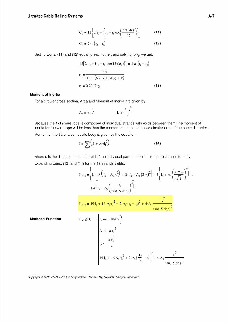
Moment of Inertia
For a circular cross section, Area and Moment of Inertia are given by:
As π rs
2
⋅= Is
π rs4
⋅
4=
Because the 1x19 wire rope is composed of individual strands with voids between them, the moment of
inertia for the wire rope will be less than the moment of inertia of a solid circular area of the same diameter.
Moment of Inertia of a composite body is given by the equation:
I
j
I j A j d j2
⋅+∑= (14)
where d is the distance of the centroid of the individual part to the centroid of the composite body.
Expanding Eqns. (13) and (14) for the 19 strands yields:
I1x19 Is 8 Is As rs2
⋅+⋅+ 2 Is As 2 rs⋅( )2
⋅+⋅+ 4 Is As
rc rs−
2
2⋅+
⋅+
4 Is As
rs
tan 15 deg⋅( )
2
⋅+
⋅+
...=
I1x19 19 Is⋅ 16 As⋅ rs2
⋅+ 2 As⋅ rc rs−( )2
⋅+ 4 As⋅rs
2
tan 15 deg⋅( )2
⋅+=
Mathcad Function: I1x19 D( ) rs 0.2047D
2⋅←
As π rs2
⋅←
Is
π rs4
⋅
4←
19 Is⋅ 16 As⋅ rs2
⋅+ 2 As⋅ D
2rs−
2
⋅+ 4 As⋅rs
2
tan 15 deg⋅( )2
⋅+
:=
Copyright © 2003-2008, Ultra-tec Corporation, Carson City, Nevada. All rights reserved.
7/21/2019 Section A - cable railing
http://slidepdf.com/reader/full/section-a-cable-railing 8/16
Ultra-tec Cable Railing Systems A-8
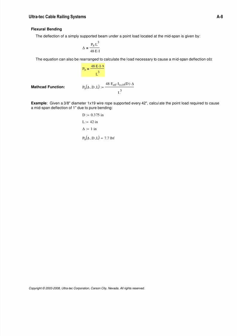
Flexural Bending
The deflection of a simply supported beam under a point load located at the mid-span is given by:
∆Pb L
3⋅
48 E⋅ I⋅=
The equation can also be rearranged to calculate the load necessary to cause a mid-span deflection of ∆:
Pb
48 E⋅ I⋅ ∆⋅
L3
=
Mathcad Function: Pb ∆ D, L,( ) 48 Eeff ⋅ I1x19 D( )⋅ ∆⋅
L3
:=
Example: Given a 3/8" diameter 1x19 wire rope supported every 42", calculate the point load required to cause
a mid-span deflection of 1" due to pure bending:
D 0.375 in⋅:=
L 42 in⋅:=
∆ 1 in⋅:=
Pb ∆ D, L,( ) 7.7 lbf =
Copyright © 2003-2008, Ultra-tec Corporation, Carson City, Nevada. All rights reserved.
7/21/2019 Section A - cable railing
http://slidepdf.com/reader/full/section-a-cable-railing 9/16
Ultra-tec Cable Railing Systems A-9
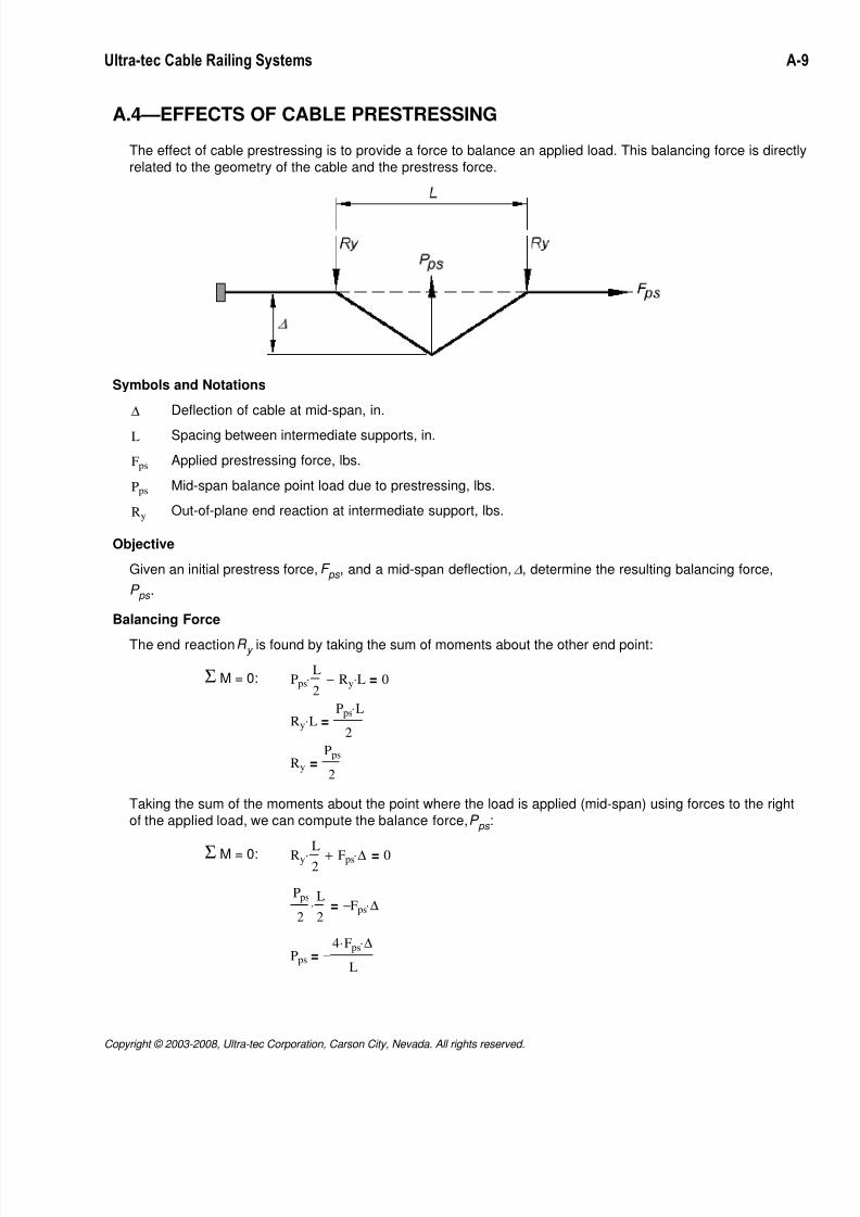
A.4—EFFECTS OF CABLE PRESTRESSING
The effect of cable prestressing is to provide a force to balance an applied load. This balancing force is directly
related to the geometry of the cable and the prestress force.
Symbols and Notations
∆ Deflection of cable at mid-span, in.
L Spacing between intermediate supports, in.
Fps Applied prestressing force, lbs.
Pps Mid-span balance point load due to prestressing, lbs.
Ry Out-of-plane end reaction at intermediate support, lbs.
Objective
Given an initial prestress force, F ps , and a mid-span deflection, ∆, determine the resulting balancing force,
P ps .
Balancing Force
The end reaction R y is found by taking the sum of moments about the other end point:
Σ M = 0: Pps
L
2⋅ Ry L⋅− 0=
Ry L⋅Pps L⋅
2=
Ry
Pps
2=
Taking the sum of the moments about the point where the load is applied (mid-span) using forces to the right
of the applied load, we can compute the balance force, P ps :
Σ M = 0: Ry L2
⋅ Fps ∆⋅+ 0=
Pps
2
L
2⋅ Fps− ∆⋅=
Pps
4 Fps⋅ ∆⋅
L−=
Copyright © 2003-2008, Ultra-tec Corporation, Carson City, Nevada. All rights reserved.
7/21/2019 Section A - cable railing
http://slidepdf.com/reader/full/section-a-cable-railing 10/16
Ultra-tec Cable Railing Systems A-10
Our applied load is equal to the magnitude of P ps , but opposite in sign. Therefore, in the context of our
applied load, the equation for P ps becomes:
Pps
4 Fps⋅ ∆⋅
L=
Mathcad Function: Pps Fps ∆, L,( ) 4 Fps⋅ ∆⋅
L:=
Example: Given a wire rope supported at 42", calculate the mid-span balancing load with a 400 lbs prestress
load and a mid-span deflection of 1":
Fps 400 lbf ⋅:=
L 42 in⋅:=
∆ 1 in⋅:=
Pps Fps ∆, L,( ) 38.1lbf =
A.5—PUTTING IT ALL TOGETHER
Symbols and Notations
∆ Deflection of cable under mid-span point load, P.
∆FpsT Change in prestress force due to temperature change, lbs.
D Diameter of wire rope cable, in.
Fps Applied prestressing force, lbs.
L Spacing between intermediate supports, in.
LT Length of cable between anchor points, ft.
P Mid-span point load required to produce deflection ∆, lbs.
Pb Component of mid-span point load, P , resisted by flexural bending, lbs.
Pef Component of mid-span point load, P , resisted by stretching of cable, lbs.
Pps Component of mid-span point load, P , resisted by cable prestressing, lbs.
Combined Load-Deflection Relationship
The effects of cable stretch, flexural beam action, and prestressing force combine to create a compositerelationship between the applied load and the deflection of the cable. That is, for a given point load, applied
at the mid-span of the cable, the cable will deflect until the load is balanced by the sum of the reactions due
to cable stretch, flexure, and prestressing force.
Recall the load-deflection relationships previously derived:
Extensible,
Flexible Cable: Pef
4 ∆⋅ E⋅ A⋅
L
4 ∆2
⋅ L2
+ L−
4 ∆2
⋅ L2
+ LT+ L−
⋅=
Copyright © 2003-2008, Ultra-tec Corporation, Carson City, Nevada. All rights reserved.
7/21/2019 Section A - cable railing
http://slidepdf.com/reader/full/section-a-cable-railing 11/16
Ultra-tec Cable Railing Systems A-11
Flexural Bending: Pb
48 E⋅ I⋅ ∆⋅
L3
=
Presstressing: Pps
4 Fps⋅ ∆⋅
L=
Strain compatibility laws tell us that when a load is applied to the cable, the deflection in each of the above
cases must the same. Therefore, for a given deflection, the applied load required to cause that deflection, P ,
is the sum of the three components:
P Pef Pb+ Pps+=
Mathcad Function: P ∆ D, L, LT, Fps,( ) Pef ∆ D, L, LT,( ) Pb ∆ D, L,( )+ Pps Fps ∆, L,( )+:=
Example: Given a 3/8" diameter 1x19 wire rope supported every 42", with an achorage distance of 24'-6", and
with a prestress load of 400 lbs., calculate the point load required to cause a mid-span deflection of 1":
D 0.375 in⋅:=
L 42 in⋅:=
LT 24.5 ft⋅:=
Fps 400 lbf ⋅:=
∆ 1 in⋅:=
P ∆ D, L, LT, Fps,( ) 73.5lbf =
Copyright © 2003-2008, Ultra-tec Corporation, Carson City, Nevada. All rights reserved.
7/21/2019 Section A - cable railing
http://slidepdf.com/reader/full/section-a-cable-railing 12/16
Ultra-tec Cable Railing Systems A-12
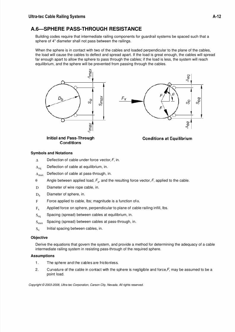
A.6—SPHERE PASS-THROUGH RESISTANCE
Building codes require that intermediate railing components for guardrail systems be spaced such that a
sphere of 4" diameter shall not pass between the railings.
When the sphere is in contact with two of the cables and loaded perpendicular to the plane of the cables,
the load will cause the cables to deflect and spread apart. If the load is great enough, the cables will spread
far enough apart to allow the sphere to pass through the cables; if the load is less, the system will reachequilibrium, and the sphere will be prevented from passing through the cables.
Symbols and Notations
∆ Deflection of cable under force vector, F , in.
∆eq Deflection of cable at equilibrium, in.
∆max Deflection of cable at pass-through, in.θ Angle between applied load, F x , and the resulting force vector, F , applied to the cable.
D Diameter of wire rope cable, in.
Db Diameter of sphere, in.
F Force applied to cable, lbs; magnitude is a function of α.
Fx Applied force on sphere, perpendicular to plane of cable railing infill, lbs.
Seq Spacing (spread) between cables at equilibrium, in.
Smax Spacing (spread) between cables at pass-through, in.
So Initial spacing between cables, in.
Objective
Derive the equations that govern the system, and provide a method for determining the adequacy of a cable
intermediate railing system in resisting pass-through of the required sphere.
Assumptions
1. The sphere and the cables are frictionless.
2. Curvature of the cable in contact with the sphere is negligible and force, F , may be assumed to be a
point load.
Copyright © 2003-2008, Ultra-tec Corporation, Carson City, Nevada. All rights reserved.
7/21/2019 Section A - cable railing
http://slidepdf.com/reader/full/section-a-cable-railing 13/16
Ultra-tec Cable Railing Systems A-13
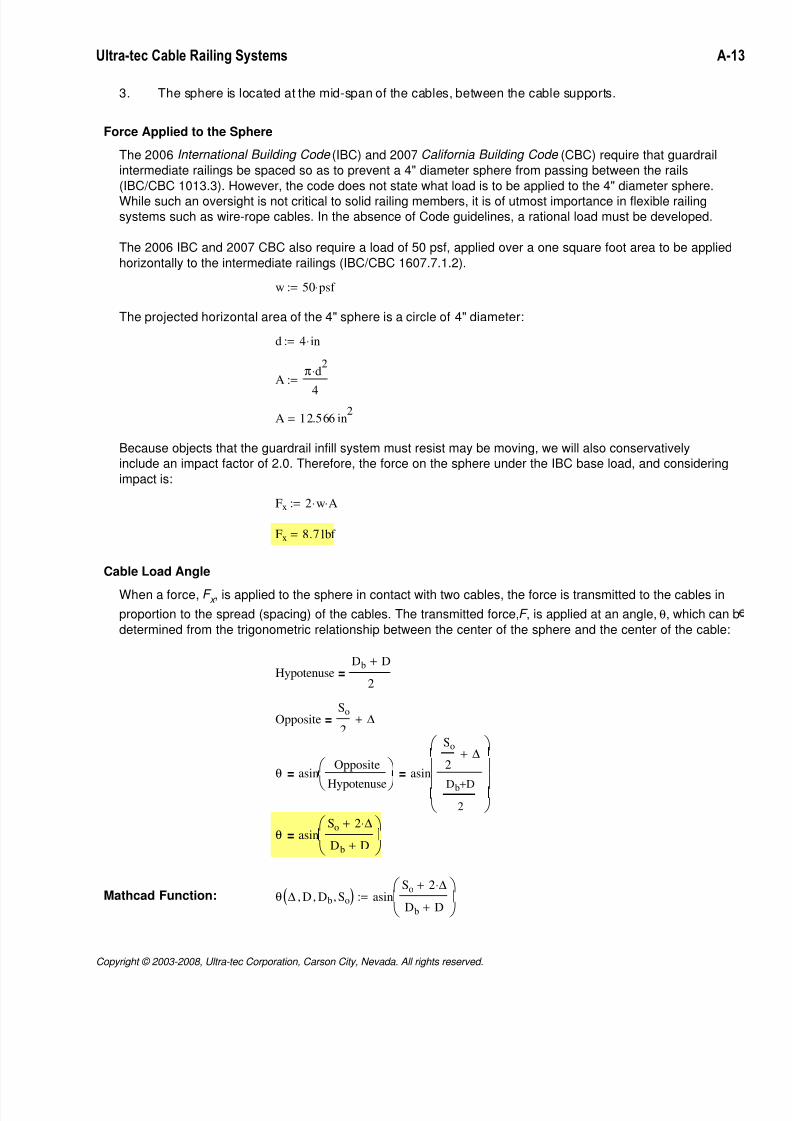
3. The sphere is located at the mid-span of the cables, between the cable supports.
Force Applied to the Sphere
The 2006 International Building Code (IBC) and 2007 California Building Code (CBC) require that guardrail
intermediate railings be spaced so as to prevent a 4" diameter sphere from passing between the rails
(IBC/CBC 1013.3). However, the code does not state what load is to be applied to the 4" diameter sphere.
While such an oversight is not critical to solid railing members, it is of utmost importance in flexible railingsystems such as wire-rope cables. In the absence of Code guidelines, a rational load must be developed.
The 2006 IBC and 2007 CBC also require a load of 50 psf, applied over a one square foot area to be applied
horizontally to the intermediate railings (IBC/CBC 1607.7.1.2).
w 50 psf ⋅:=
The projected horizontal area of the 4" sphere is a circle of 4" diameter:
d 4 in⋅:=
Aπ d
2⋅
4
:=
A 12.566 in2
=
Because objects that the guardrail infill system must resist may be moving, we will also conservatively
include an impact factor of 2.0. Therefore, the force on the sphere under the IBC base load, and considering
impact is:
Fx 2 w⋅ A⋅:=
Fx 8.7 lbf =
Cable Load Angle
When a force, F x , is applied to the sphere in contact with two cables, the force is transmitted to the cables in
proportion to the spread (spacing) of the cables. The transmitted force, F , is applied at an angle, θ, which can b
determined from the trigonometric relationship between the center of the sphere and the center of the cable:
HypotenuseDb D+
2=
OppositeSo
2∆+=
θ asinOpposite
Hypotenuse
= asin
So
2∆+
Db D+
2
=
θ asinSo 2 ∆⋅+
Db D+
=
Mathcad Function: θ ∆ D, Db, So,( ) asinSo 2 ∆⋅+
Db D+
:=
Copyright © 2003-2008, Ultra-tec Corporation, Carson City, Nevada. All rights reserved.

7/21/2019 Section A - cable railing
http://slidepdf.com/reader/full/section-a-cable-railing 14/16
Ultra-tec Cable Railing Systems A-14
Example: Given two 3/8" diameter wire rope cables with an initial spacing of 3" supporting a 4" diameter
sphere. Calculate the angle at which the load is applied to each of the two cables when the sphere first
contacts the cables (i.e., ∆ = 0).
Db 4 in⋅:=
D 0.375 in⋅:=
So 3 in⋅:=
∆ 0 in⋅:=
θ ∆ D, Db, So,( ) 43.292deg=
Force Applied to Cable
Knowing the angle θ, the force applied to the cable can be easily calculated:
F
Fx
2
cos θ( )=
FFx
2 cos θ( )⋅=
Note that as the cables spread farther apart, angle θ increases. As θ increases, cos(θ) decreases. Since
the cosine term is in the denominator, as cos(θ) decreases, the force, F , applied to the cable increases. As
θ approaches 90°, F approaches infinity.
Mathcad Function: F Fx ∆, D, Db, So,( ) Fx
2 cos θ ∆ D, Db, So,( )( )⋅:=
Example: Given two 3/8" diameter wire rope cables with an initial spacing of 3" supporting a 4" diameter
sphere with a 10 lb load. Calculate the load applied to each of the two cables if the final cable spacing is
3.75".
Fx 10 lbf ⋅:=
Db 4 in⋅:=
D 0.375 in⋅:=
So 3 in⋅:=
Sfinal 3.75 in⋅:=
∆Sfinal So−
2:= ∆ 0.375 in=
F Fx ∆, D, Db, So,( ) 9.707 lbf =
Maximum Cable DeflectionThe cable spread at pass-through is equal to the sum of the sphere diameter and the cable diameter:
Smax Db D+=
The maximum cable deflection occurs at pass-through, and is equal to one-half of the difference between
the maximum cable spread and the initial cable spacing:
∆max
Smax So−
2=
Copyright © 2003-2008, Ultra-tec Corporation, Carson City, Nevada. All rights reserved.
7/21/2019 Section A - cable railing
http://slidepdf.com/reader/full/section-a-cable-railing 15/16
Ultra-tec Cable Railing Systems A-15
∆max
Db D+ So−
2=
Mathcad Function: ∆max D Db, So,( ) Db D+ So−
2:=
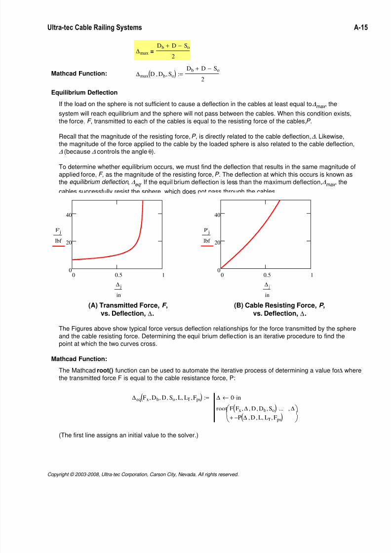
Equilibrium Deflection
If the load on the sphere is not sufficient to cause a deflection in the cables at least equal to ∆max , the
system will reach equilibrium and the sphere will not pass between the cables. When this condition exists,
the force, F , transmitted to each of the cables is equal to the resisting force of the cables, P .
Recall that the magnitude of the resisting force, P , is directly related to the cable deflection, ∆. Likewise,
the magnitude of the force applied to the cable by the loaded sphere is also related to the cable deflection,
∆ (because ∆ controls the angle θ).
To determine whether equilibrium occurs, we must find the deflection that results in the same magnitude of
applied force, F , as the magnitude of the resisting force, P . The deflection at which this occurs is known as
the equilibrium deflection , ∆eq . If the equil brium deflection is less than the maximum deflection, ∆max , the
cables successfully resist the sphere, which does not pass through the cables
0 0.5 10
20
40
F' j
lbf
∆ j
in
0 0.5 10
20
40
P' j
lbf
∆ j
in
(A) Transmitted Force, F ,
vs. Deflection, ∆.
(B) Cable Resisting Force, P ,
vs. Deflection, ∆.
The Figures above show typical force versus deflection relationships for the force transmitted by the sphere
and the cable resisting force. Determining the equil brium deflection is an iterative procedure to find the
point at which the two curves cross.
Mathcad Function:
The Mathcad root() function can be used to automate the iterative process of determining a value for ∆ where
the transmitted force F is equal to the cable resistance force, P:
∆eq Fx Db, D, So, L, LT, Fps,( ) ∆ 0 in⋅←
root F Fx ∆, D, Db, So,( )P ∆ D, L, LT, Fps,( )−+
... ∆,
:=
(The first line assigns an initial value to the solver.)
Copyright © 2003-2008, Ultra-tec Corporation, Carson City, Nevada. All rights reserved.
7/21/2019 Section A - cable railing
http://slidepdf.com/reader/full/section-a-cable-railing 16/16
Ultra-tec Cable Railing Systems A-16
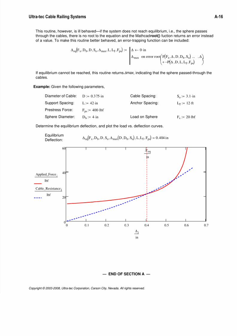
This routine, however, is ill behaved—if the system does not reach equilibrium, i.e., the sphere passes
through the cables, there is no root to the equation and the Mathcad root() fuction returns an error instead
of a value. To make this routine better behaved, an error-trapping function can be included:
∆eq Fx Db, D, So, ∆max, L, LT, Fps,( ) ∆ 0 in⋅←
∆max
root F Fx ∆, D, D
b, S
o,
( )P ∆ D, L, LT, Fps,( )−+
... ∆,
on error
:=
If equilibrium cannot be reached, this routine returns ∆max , indicating that the sphere passed-through the
cables.
Example: Given the following parameters,
Diameter of Cable: D 0.375 in⋅:= Cable Spacing: So 3.1 in⋅:=
Support Spacing: L 42 in⋅:= Anchor Spacing: LT 12 ft⋅:=
Prestress Force: Fps 400 lbf ⋅:=
Sphere Diameter: Db 4 in⋅:= Load on Sphere Fx 20 lbf ⋅:=
Determine the equilibrium deflection, and plot the load vs. deflection curves.
Equilibrium
Deflection: ∆eq Fx Db, D, So, ∆max D Db, So,( ), L, LT, Fps,( ) 0.404 in=
0 0.1 0.2 0.3 0.4 0.5 0.6 0.70
20
40
60
Applied_Force j
lbf
Cable_Resistance j
lbf
∆'eq
in
∆ j
in
— END OF SECTION A —
Copyright © 2003-2008, Ultra-tec Corporation, Carson City, Nevada. All rights reserved.