Section 7010 - Portland Cement Concrete Pavement Standard Specifications Division 7 - Streets and...
56
SUDAS Standard Specifications Division 7 - Streets and Related Work Section 7010 - Portland Cement Concrete Pavement 1 Revised: 2018 Edition PORTLAND CEMENT CONCRETE PAVEMENT PART 1 - GENERAL 1.01 SECTION INCLUDES A. Pavement B. Curb and Gutter 1.02 DESCRIPTION OF WORK Includes the requirements for the construction of full depth PCC pavement and curb and gutter. 1.03 SUBMITTALS Comply with Division 1 - General Provisions and Covenants, as well as the following: A. Two weeks prior to commencing any PCC pavement placement, submit a paving mix design for each different source of aggregate to be used for review and approval by the Engineer. Submit mixes or mix designs approved by the Iowa Department of Transportation or an independent testing laboratory. B. Maturity curves for paving mixes and maturity reading results. C. Submit all testing and certifications according to Section 7010, 3.07. 1.04 SUBSTITUTIONS Comply with Division 1 - General Provisions and Covenants. 1.05 DELIVERY, STORAGE, HANDLING, AND SALVAGING Comply with Division 1 - General Provisions and Covenants, as well as the following: A. Aggregate Storage: Comply with Iowa DOT Article 2301.02, C. B. Cement and Fly Ash: Comply with Iowa DOT Article 2301.02, C. C. Admixtures: Store in suitable weather tight enclosures which will preserve quality. D. Reinforcing Steel: Store off ground on timbers or other supports. 1.06 SCHEDULING AND CONFLICTS Comply with Division 1 - General Provisions and Covenants, as well as the following: Complete elements of the work that can affect line and grade in advance of other open cut construction unless noted on plans. 1.07 SPECIAL REQUIREMENTS None
Transcript of Section 7010 - Portland Cement Concrete Pavement Standard Specifications Division 7 - Streets and...

SUDAS Standard Specifications Division 7 - Streets and Related Work Section 7010 - Portland Cement Concrete Pavement
1 Revised: 2018 Edition
PORTLAND CEMENT CONCRETE PAVEMENT PART 1 - GENERAL 1.01 SECTION INCLUDES
A. Pavement B. Curb and Gutter
1.02 DESCRIPTION OF WORK
Includes the requirements for the construction of full depth PCC pavement and curb and gutter.
1.03 SUBMITTALS Comply with Division 1 - General Provisions and Covenants, as well as the following: A. Two weeks prior to commencing any PCC pavement placement, submit a paving mix design
for each different source of aggregate to be used for review and approval by the Engineer. Submit mixes or mix designs approved by the Iowa Department of Transportation or an independent testing laboratory.
B. Maturity curves for paving mixes and maturity reading results. C. Submit all testing and certifications according to Section 7010, 3.07.
1.04 SUBSTITUTIONS Comply with Division 1 - General Provisions and Covenants.
1.05 DELIVERY, STORAGE, HANDLING, AND SALVAGING Comply with Division 1 - General Provisions and Covenants, as well as the following: A. Aggregate Storage: Comply with Iowa DOT Article 2301.02, C. B. Cement and Fly Ash: Comply with Iowa DOT Article 2301.02, C. C. Admixtures: Store in suitable weather tight enclosures which will preserve quality. D. Reinforcing Steel: Store off ground on timbers or other supports.
1.06 SCHEDULING AND CONFLICTS Comply with Division 1 - General Provisions and Covenants, as well as the following: Complete elements of the work that can affect line and grade in advance of other open cut construction unless noted on plans.
1.07 SPECIAL REQUIREMENTS None

SUDAS Standard Specifications Division 7 - Streets and Related Work Section 7010 - Portland Cement Concrete Pavement
2 Revised: 2018 Edition
1.08 MEASUREMENT AND PAYMENT A. PCC Pavement:
1. Measurement: Measurement will be in square yards for each different thickness of PCC pavement. The area of manholes, intakes, or other fixtures in the pavement will not be deducted from the measured pavement area.
2. Payment: Payment will be at the unit price per square yard for each thickness of PCC
pavement. 3. Includes: Unit price includes, but is not limited to, final trimming of subgrade or subbase,
integral curb, bars and reinforcement, joints and sealing, surface curing and pavement protection, safety fencing, concrete for rigid headers, boxouts for fixtures, pavement smoothness testing, and quality control for stringless paving.
B. Air Content Deficiency:
1. Measurement: Measurement will be in square yards for each different thickness of PCC pavement subject to a unit price reduction for air content deficiency according to Section 7010, 3.07.
2. Payment: Payment will be at the reduced unit price according to Table 7010.03 for each
thickness of PCC pavement. If there is an air content deficiency on a privately contracted roadway project, the Jurisdiction ultimately accepting ownership of the roadway will receive the penalty payment prior to acceptance of the work.
C. Pavement Smoothness Deficiency:
1. Measurement: Measurement will be in square yards for each different thickness of PCC pavement subject to a unit price reduction for pavement smoothness according to Section 7010, 3.07.
2. Payment: Payment will be at the reduced unit price according to Table 7010.04 for each
thickness of PCC pavement. If there is a pavement smoothness deficiency on a privately contracted roadway project, the Jurisdiction ultimately accepting ownership of the roadway will receive the penalty payment prior to acceptance of the work.
D. PCC Pavement Thickness Deficiency:
1. Measurement: Measurement will be in square yards for each different thickness of PCC pavement that has deficient pavement thickness as determined in Table 7010.05.
2. Payment: Payment will be at the percentage of the unit price indicated in Table 7010.05
for each different thickness of PCC pavement. If there is a pavement thickness deficiency on a privately contracted roadway project, the Jurisdiction ultimately accepting ownership of the roadway will receive the penalty payment prior to acceptance of the work.
E. Curb and Gutter:
1. Measurement: Measurement will be in linear feet measured along the face of the curb for each different width and thickness of curb and gutter.
2. Payment: Payment will be at the unit price per linear feet of curb and gutter. 3. Includes: Unit price includes, but is not limited to, final subgrade/subbase preparation,
bars and reinforcement, joints and sealing, surface curing and pavement protection, and boxouts for fixtures.

SUDAS Standard Specifications Division 7 - Streets and Related Work Section 7010 - Portland Cement Concrete Pavement
3 Revised: 2018 Edition
1.08 MEASUREMENT AND PAYMENT (Continued)
F. Beam Curb:
1. Measurement: Measurement will be in linear feet measured along the face of the curb. 2. Payment: Payment will be at the unit price per linear feet of beam curb. 3. Includes: Unit price includes, but is not limited to, final subgrade/subbase preparation,
bars and reinforcement, joints and sealing, surface curing and pavement protection, and boxouts for fixtures.
G. Concrete Median:
1. Measurement: Measurement will be in square yards of concrete median. When the curb is integral with the pavement, the width will be measured from back of curb to back of curb.
2. Payment: Payment will be at the unit price per square yard of concrete median. 3. Includes: Unit price includes, but is not limited to, final subgrade/subbase preparation,
bars and reinforcement, joints and sealing, surface curing and pavement protection, and boxouts for fixtures.
H. Fixture Adjustment: Comply with Section 6010 for adjustment of manholes and intakes and
Section 5020 for adjustment of water valves and fire hydrants. I. PCC Pavement Samples and Testing:
1. Measurement: Lump sum item; no measurement will be made. 2. Payment: Payment will be at the lump sum price for PCC pavement samples and
testing. 3. Includes: Lump sum price includes, but is not limited to, certified plant inspection,
pavement thickness cores, profilograph pavement smoothness measurement (when required by the contract documents), and maturity testing.
J. Granular Surfacing: Comply with Section 7030 for granular surfacing material placed at
intersecting roads, driveways, and turnouts. K. PCC Pavement Widening:
1. Measurement: Measurement will be in square yards for each different thickness of PCC pavement widening. The area of manholes, intakes, or other fixtures in the pavement will not be deducted from the measured pavement widening area.
2. Payment: Payment will be at the unit price per square yard for each thickness of PCC
pavement widening. 3. Includes: Unit price includes, but is not limited to, final subgrade/subbase preparation,
integral curb, bars and reinforcement, joints and sealing, surface curing and pavement protection, safety fencing, concrete for rigid headers, boxouts for fixtures, and pavement smoothness.
L. Pavement Removal: Comply with Section 7040.

SUDAS Standard Specifications Division 7 - Streets and Related Work Section 7010 - Portland Cement Concrete Pavement
4 Revised: 2018 Edition
PART 2 - PRODUCTS 2.01 MATERIALS
A. Cement: Meet the requirements of Iowa DOT Section 4101 and Materials I.M. 401, including
Type I and Type II cements and blended hydraulic cements Type 1P, Type 1S, and Type 1L. B. Supplementary Cementitious Materials (SCM):
1. Fly Ash: Comply with Iowa DOT Section 4108. 2. Ground Granulated Blast Furnace Slag (GGBFS): Comply with Iowa DOT Section
4108. 3. Limestone: Comply with Iowa DOT Materials I.M. 401.
C. Fine Aggregate for Concrete:
1. Meet the requirements of Iowa DOT Section 4110 and Materials I.M. 409, Source Approvals for Aggregates.
2. Comply with the following gradation:
Sieve Size Percent Passing
3/8” 100
No. 4 90 to 100
No. 8 70 to 100
No. 30 10 to 60
No. 200 0 to 1.5 Iowa DOT Article 4109.02, Gradation No. 1 in the Aggregate Gradation Table.
3. The Engineer may authorize a change in gradation, subject to materials available locally at the time of construction.
D. Coarse Aggregate for Concrete:
1. Crushed stone particles with Class 2 durability complying with Iowa DOT Section 4115 and Materials I.M. 409, Source Approvals for Aggregates.
2. Comply with one of the following gradations:
Sieve Size Gradation No. 3 Percent Passing
Gradation No. 4 Percent Passing
Gradation No. 5 Percent Passing
1 1/2” 100 100 -----
1” 95 to 100 50 to 100 100
3/4” ----- 30 to 100 90 to 100
1/2” 25 to 60 20 to 75 -----
3/8” ----- 5 to 55 20 to 55
No. 4 0 to 10 0 to 10 0 to 10
No. 8 0 to 5 0 to 5 0 to 5
No. 200 0 to 1.5 0 to 1.5 0 to 1.5 Iowa DOT Article 4109.02, Gradation No. 3, 4, and 5 in the Aggregate Gradation Table.
3. The Engineer may authorize a change in gradation, subject to materials available locally at the time of construction.

SUDAS Standard Specifications Division 7 - Streets and Related Work Section 7010 - Portland Cement Concrete Pavement
5 Revised: 2018 Edition
2.01 MATERIALS (Continued) E. Intermediate Aggregate for Concrete: Use if specified in contract documents.
1. Meet the requirements of Iowa DOT Section 4112 and Materials I.M. 409, Source Approvals for Aggregates.
2. For crushed limestone or dolomite, meet the durability class required for the coarse
aggregate. When gravel durability is lower than the coarse aggregate durability requirements, pea gravel is not to exceed 15% of the total aggregate mix.
3. Comply with the following aggregate gradation:
Sieve Size Percent Passing
1/2” 95 to 100
3/8” -----
No. 4 -----
No. 8 0 to 10 Iowa DOT Article 4109.02, Gradation No. 2 in the Aggregate Gradation Table
4. The Engineer may authorize a change in gradation subject to materials locally available
at the time of construction.
F. Water Requirements: Comply with Iowa DOT Section 4102. Potable water obtained from a municipal supply, suitable for drinking, may be accepted without testing.
G. Admixtures: Meet the requirements for the liquid admixtures shown below. Other
admixtures may be used subject to the approval of the Engineer.
1. Air Entrainment Admixture: Comply with Iowa DOT Section 4103. 2. Retarding and Water Reducing Admixtures: Comply with Iowa DOT Section 4103. 3. Accelerating admixtures (calcium chloride): Comply with Iowa DOT Article 2529.02.
H. Bars: Comply with Iowa DOT Section 4151 for tie bars and dowel bars. Meet the tie bar requirements for bar mats. All bars must be epoxy coated.
I. Expansion Tubes: Comply with Iowa DOT Section 4191. J. Metal Keyways: Comply with Iowa DOT Section 4191. K. Supports for Bars: Comply with Iowa DOT Materials I.M. 451.01. L. Joint Fillers and Sealers:
1. Joint Sealers: Comply with Iowa DOT Article 4136.02. 2. Preformed Expansion Joint Fillers and Sealers: Use the following types of preformed
materials for filling expansion joints that comply with Iowa DOT Article 4136.03. When the type is not specified, use a resilient filler.
Resilient filler
Flexible foam expansion joint filler
Tire buffings expansion joint filler
Elastomeric joint seals 3. Backer Rod: Comply with Iowa DOT Section 4136.

SUDAS Standard Specifications Division 7 - Streets and Related Work Section 7010 - Portland Cement Concrete Pavement
6 Revised: 2018 Edition
2.01 MATERIALS (Continued) M. Liquid Curing Compound: Comply with Iowa DOT Section 4105. N. Covering:
1. Burlap: Comply with Iowa DOT Section 4104. 2. Plastic Film: Comply with Iowa DOT Section 4106. 3. Insulating Cover: Comply with Iowa DOT Section 4106.
O. Grout Systems: Use polymer grouts that comply with Iowa DOT Materials I.M. 491.11.
2.02 CONCRETE MIXES A. Mix Design:
1. Comply with Iowa DOT Class C or Class M mix meeting the requirements of Materials I.M. 529. If higher durability mixes are specified, use C-SUD or CV-SUD mixes.
2. Ensure compatibility of all material combinations. If the concrete materials are not
producing a workable concrete mixture, a change in the material may be required. Changes will be at no additional cost to the Contracting Authority.
B. Consistency and Workability:
1. Slump: a. Use an amount of mixing water that will produce workable concrete of uniform
consistency. Unless specifically modified by the Engineer, ensure slump, measured according to Iowa DOT Materials I.M. 317, is no less than 1/2 inch or no more than 2 1/2 inches for machine finish and no less than 1/2 inch and no more than 4 inches for hand finish.
b. If it is not possible to produce concrete having the required consistency without exceeding the maximum allowable water to cement ratio specified, the cement content may be increased or water reducing admixture may be added. Obtain the Engineer’s approval. Do not exceed the maximum water to cement ratio. Additional cement or water reducer will be added with no additional cost to the Contracting Authority.
c. The basic absolute volume of water per unit volume of concrete is based on average conditions. If material characteristics require that the total quantity of water used to secure the required consistency reduces the batch yield (computed on the basis of absolute volumes of the batch quantities used) by more than 2.0%, the Engineer may adjust the proportions to correct the yield. This adjustment will not be a basis for adjustment of the contract unit price.
2. Air Content: Use an approved air entraining agent.
a. For machine-placed pavement, use a target air content of 8% with a tolerance of plus or minus 2% when measured on the grade just prior to consolidation, as determined by Iowa DOT Materials I.M. 318. The target air content may be adjusted by the Engineer based on random tests of the consolidated concrete behind the paving machine. These additional tests will be used to consider the need for a target value change and will not be used in the acceptance decision.
b. For hand-placed pavement, use a target content for hand finish of 7% with a tolerance of plus or minus 1.5% when measured on the grade and just prior to consolidation, as determined by Iowa DOT Materials I.M. 318.

SUDAS Standard Specifications Division 7 - Streets and Related Work Section 7010 - Portland Cement Concrete Pavement
7 Revised: 2018 Edition
2.02 CONCRETE MIXES (Continued)
C. Use of Fly Ash and Ground Granulated Blast Furnace Slag (GGBFS) as Supplementary Cementitious Materials:
1. Mix proportions for the various mixes using fly ash and GGBFS are included in Iowa DOT
Materials I.M. 529. The maximum allowable fly ash substitution rate is 20%. Do not use a GGBFS substitution rate of more than 35% by weight (mass). The total supplementary cementitious material substitution rate is not to exceed 40%.
2. If C-SUD or CV-SUD mixes are specified, the maximum allowable Class F fly ash
substitution rate is 25% and the maximum Class C fly ash substitution rate is 35%. The maximum combination rate is 20% Class C fly ash and 20% GGBFS.
3. When Type IP or IS cement is used in the concrete mixture, only fly ash substitution will
be allowed. Between October 16 and March 15, supplementary cementitious materials will be allowed only when maturity method is used to determine time of opening. Transport, store, haul, and batch fly ash and GGBFS in such a manner to keep it dry.
SUDAS Standard Specifications Division 7 - Streets and Related Work Section 7010 - Portland Cement Concrete Pavement
8 Revised: 2018 Edition
PART 3 - EXECUTION 3.01 EQUIPMENT
A. Batching and Mixing Equipment:
1. General: a. Weighing and Proportioning Equipment: Comply with Iowa DOT Article 2001.20. b. Mixing Equipment: Comply with Iowa DOT Article 2001.21. c. Material Bins: Involves any structure in which materials are stored. Each part of
any bin, including foundations and supports, must be adequate to withstand any stress to which it might be subjected to while in use.
2. Batching:
a. Ensure the batching plant is Iowa DOT calibrated and approved. Provide copy of current calibrations and approvals.
b. Coordinate the batch plant operation and batch trucks with the paving operation in order to ensure a steady supply of materials.
c. Operate the batch plant and trucks to minimize dust, noise, or truck nuisances.
3. Mixing: a. Construction or Stationary Mixer:
1) Ensure the concrete is uniform in composition and consistency. If this condition is not produced because of the size of the batch, the size of the batch may be reduced or the mixing time increased, or both, until this result is obtained. If non-uniform, corrective action must be taken.
2) Ensure the methods of delivering and handling the concrete are such that objectionable segregation or damage to the concrete will not occur, and they will facilitate placing with a minimum of handling.
b. Ready Mixed Concrete: 1) Ensure the concrete is uniform in composition and consistency. If non-uniform,
concrete producers must take corrective action. 2) Ready mixed concrete is defined as concrete proportioned in a central plant and
mixed in a stationary mixer for transportation in trucks without agitation, proportioned at a central plant, and only partially mixed in a stationary mixer for transportation and finish mixing in a transit mixer, or proportioned at a central plant, and then mixed in a transit mixer prior to or during transit.
3) When necessary to add additional mixing water at the site of placement, mix the batch at least an additional 30 revolutions of the drum at mixing speed.
4) Ensure each vehicle in which concrete will be delivered is capable of discharging concrete having a slump not over 2 inches at an overall rate for its entire load of not less than 1.25 cubic yards per minute. Ensure the concrete is delivered at a rate sufficient to maintain a sustained rate of progress of not less than 100 feet per hour for the width and depth of pavement to be placed.
c. All Methods: Identify each truck load by a plant charge ticket showing plant name, contractor, project data, quantity, class, time batched, and water added at site.
B. Concrete Delivery Equipment:
1. General: a. In handling concrete from the mixer to the place of deposit, take care to avoid
segregation. b. When concrete is deposited through a chute, slope the chute to allow concrete to flow
slowly without segregation. Place the delivery point of the chute as close as possible to the point of deposit. Keep chutes and spouts clean. Thoroughly flush them with water before and after each run. Discharge the water outside the paving area in an approved concrete washout area.

SUDAS Standard Specifications Division 7 - Streets and Related Work Section 7010 - Portland Cement Concrete Pavement
9 Revised: 2018 Edition
3.01 EQUIPMENT (Continued)
c. Provide alternate plan for concrete delivery in event of equipment failure. d. Take concrete samples from material placed on the subgrade or subbase.
2. Concrete Transfer Equipment: a. Utilize placers, conveyors, buckets, or buggies designed specifically for transporting
concrete. b. Do not allow concrete to free fall into or out of transfer equipment. c. Meet the requirements of Section 7010, 2.02, B, 2 for air entrainment of the concrete
mix and testing for compliance.
3. Concrete Pumps: a. Do not pump concrete through aluminum conduit or tubing. b. Use the concrete pump to deliver the material as close to horizontal as possible,
keep restrictions and drops to a minimum, and avoid free fall. c. Meet the requirements of Section 7010, 2.02, B, 2 for air entrainment of the concrete
mix and testing for compliance. d. Sample the first load after pumping a minimum of 3 cubic yards. Sample after each
significant change in boom angle. e. Sample before and after the pump to determine if any changes in the slump and
other significant mixture characteristics occur. f. When sampling at the end of the placement line, take care to ensure that the sample
is representative of the concrete being placed from the pipeline. Note: Changes to the placement rate or boom configuration can result in changes in the concrete properties. Typically, the vertical position of the boom results in the greatest potential for air loss while the horizontal position of the boom has the least potential. Location of pumping equipment should be determined so that it is possible to maintain a consistent, low boom angle as much as possible during placement.
g. If air test shows that air entrainment is outside of the allowed range, follow procedure as outlined in Section 7010, 3.07, B.
h. Leaks in the line or pump hydraulics, which would allow air to be added to the concrete, are prohibited.
C. Concrete Placement Equipment:
1. Consolidating and Finishing Equipment: a. Use a paving machine that meets all of the following:
1) Is designed for the specific purpose of placing, consolidating, and finishing concrete pavement.
2) Develops vertical edges on the pavement. 3) Is self propelled and equipped with a means for spreading the concrete to a
uniform depth before it enters the throat. 4) Vibrates the concrete to the full width and depth being placed in a single
passage. Use vibrating tubes or arms working in the concrete or a vibrating pan operating on the surface of the concrete.
5) Produces a surface reasonably free of voids and tears. 6) When the paver is operated on previously placed concrete, prevent damage to
the pavement surface. 7) For slip form pavers, use a paver equipped with automatic horizontal and vertical
grade controls. b. Hand methods utilizing air screeds and vibrating screeds may be used for short
pavement runs, cul-de-sacs, driveways, and some intersections. c. When allowed by the Engineer, use stringless paving equipment capable of providing
the same accuracy necessary to comply with the requirements of Section 7010.

SUDAS Standard Specifications Division 7 - Streets and Related Work Section 7010 - Portland Cement Concrete Pavement
10 Revised: 2018 Edition
3.01 EQUIPMENT (Continued)
d. Use a laser guided screed that meets all of the following: 1) Designed for the specific purpose of placing and finishing of concrete pavement
using a 3-dimensional surface model. 2) All equipment for laser guided screed, including the guidance system, will meet
the project design model tolerances. 3) Will provide consolidation to full width and full depth of concrete placement.
Provide intermediate consolidation by using external hand held vibrators. 4) Produces a surface reasonably free of voids and tears. 5) Provide boom-style screed (drive-in screeds are not allowed) with an auger
boom, placement head (water spray mechanism not allowed), guidance equipment, and software to produce 3-dimensional surface.
6) Produces pavement smoothness as specified in Section 7010, 3.07, C.
2. Vibrators for Machine Paving: a. Consolidate, with a single pass of an approved internal or surface vibrator, the full
width and depth of concrete requiring a finishing machine. Operate internal vibrators within a frequency range of 4,000 to 8,000 vibrations per minute. The Engineer may authorize the minimum vibration frequency to be lowered to 3,500 vibrations per minute for particular sections of paving, such as superelevations. Operate surface vibrators within a frequency range of 3,500 to 6,000 vibrations per minute.
b. Avoid operating vibrators in a manner to cause a separation of the mix ingredients, either a downward displacement of large aggregate particles or an accumulation of laitance on the surface of the concrete. When forward motion of the paver is reduced, vibrator frequency may need to be reduced to avoid separation of the mix.
c. If a vibrator fails to operate within the specifications, repair or change the vibrator before the paving begins:
The following day, or
The same day if the continuous paving that day is stopped at a header or at the end of a session.
d. If two adjacent vibrators fail to operate within the specifications, stop the paving operation and repair or replace the vibrators.
e. Stop vibrators whenever forward motion of the paver is stopped. f. Set the internal vibrator penetration depth into the concrete pavement to mid slab or
as deep as possible while passing above reinforcing steel. Provide an operating position locking device so that no part of the vibrating unit can be lowered to the extent that it will come in contact with reinforcing steel or tie bars while paving.
g. Do not exceed the manufacturer’s recommendations for vibrator horizontal spacing. Do not exceed 16 inches from center to center.
h. Mount the longitudinal axis of the vibrator body approximately parallel to the direction of paving. Tilt the trailing end of each vibrator downward to an approximate slope of 15 degrees below horizontal.
i. Use vibrators that meet or exceed the following specifications at the manufacturer's design frequency of 10,000 vpm: 1) Amplitude (peak to peak) 0.070 inches. 2) Centrifugal force 1,200 pounds.
3. Vibrators for Hand Methods: Use a vibration rate between 3,500 to 6,000 vibrations per minute, and use an amplitude sufficient to be perceptible on the surface of the concrete more than 12 inches from the vibrating unit.
4. Hand Finishing Equipment: Provide all finishing tools necessary for proper finishing of
the concrete including straightedges for checking and correcting finished concrete surfaces.
SUDAS Standard Specifications Division 7 - Streets and Related Work Section 7010 - Portland Cement Concrete Pavement
11 Revised: 2018 Edition
3.01 EQUIPMENT (Continued)
5. Forms: a. Rigid Forms: Steel, minimum thickness of 5 gage, height at least equal to design
thickness of pavement with base width at least 6 inches. 1) Minimum section length of 10 feet, joint connections designed to allow horizontal
and vertical adjustment with locking device to hold abutting sections firmly in alignment.
2) Bracing, support, and staking must prevent deflection or movement of forms.
b. Flexible Forms: Use steel or wood flexible forms for curves with a radius less than 100 feet. 1) Bracing, support, and staking must prevent deflection or movement of forms. 2) Ensure that forms used to shape back of curbs at returns have height at least
equal to design thickness of pavement and curb height. 3) Forms must be free from scale and surface irregularities.
6. Curing Equipment: Use pressure sprayer capable of applying a continuous uniform film of curing compound. Use equipment with a shield if wind conditions do not allow proper coverage
7. Concrete Saws: Use power operated concrete saws capable of cutting hardened
concrete neatly. 8. Joint Sealing Equipment: Use equipment capable of cleaning the joint and heating and
installing sealant in joints according to manufacturer's recommendations.
3.02 PAVEMENT CONSTRUCTION A. Removal of Pavement: Comply with Section 7040, 3.02. B. Final Subgrade/Subbase Preparation:
1. General: a. Meet the requirements of Section 2010 for subgrade construction, subgrade
treatment, and subbase construction. b. Trim the subgrade or subbase to the final grade for placement of concrete. c. Unless otherwise ordered by the Engineer, the subgrade or subbase, at time of
placing concrete for concrete pavement, must be in a uniformly moist but not muddy condition to a depth of not less than 1 inch.
2. Subgrade and Subbase Loading:
a. Travel of concrete delivery trucks on a subgrade or subbase must be approved by the Engineer. In such cases, watering of the subgrade or subbase must be limited to just ahead of the paving machine.
b. Enter and exit from side streets to minimize repetitive loading on the subgrade or subbase by concrete trucks.
c. Do not allow loads in excess of the legal axle load on the completed subgrade or subbase.
d. Partially loaded trucks may be required. e. If subgrade or subbase failure occurs, coordinate the repair with the Engineer.
3. Paving Suspended: a. Suspend the paving operation where subgrade or subbase stability has been lost. b. Do not place concrete on a subgrade or subbase that has become unstable, bears
ruts or tire marks of equipment, or that is excessively softened by rain until such subgrade or subbase has been reconsolidated and reshaped to correct the objectionable condition.

SUDAS Standard Specifications Division 7 - Streets and Related Work Section 7010 - Portland Cement Concrete Pavement
12 Revised: 2018 Edition
3.02 PAVEMENT CONSTRUCTION (Continued)
c. If necessary, scarify to a minimum depth of 6 inches, aerating, and recompacting at no additional cost to the Contracting Authority. Meet the compaction requirements of Section 2010, 3.06.
4. Maintenance of Subgrade or Subbase: Maintain the completed subgrade or subbase
during subsequent construction activities.
C. Surface Fixture Adjustment:
1. Adjust manhole frames and other fixtures within area to be paved to conform to finished surface. Comply with Section 6010, 3.04 for manhole adjustments and Section 5020, 3.04 for water fixture adjustments.
2. Clean outside of fixture to depth of pavement before concrete placement. 3. Construct boxouts where allowed for later adjustment of fixtures. See Figure 7010.103
for the size and shape of the boxout.
D. Setting of Forms: When forms are used, meet the following requirements.
1. Ensure forms have sufficient strength to support paving operations being used. 2. Set base of forms at or below subgrade elevation with top of forms at pavement surface
elevation. With Engineer approval, extra height forms may be used to shape the back of integral curb and edge of pavement; set base at or below subgrade elevation with top of form at top of curb elevation.
3. Place and secure forms to required grade and alignment. Do not vary the top face of the
form from a true plane by more than 1/8 inch in 10 feet, and do not vary the vertical face from a true plane by more than 1/4 inch in 10 feet.
4. If the soil supporting the forms is softened by rain or standing water so that the forms are
inadequately supported, or if voids occur under the forms, remove forms. Rework subgrade to proper elevation and density, and reinstall forms.
5. Ensure forms are free of latent concrete and coated with release agent before concrete is
placed.
E. Bar and Reinforcement Placement: Ensure bars are clean, straight, free from distortion and rust, and are firmly secured in position as specified in the contract documents. Place all bars in approved storage to prevent damage; do not distribute along the work site except as needed to avoid delay in paving.
1. Tie Bars:
a. Place bars prior to vibration. For slip form paving, tie bars may be installed after vibration, provided the concrete is consolidated around the bars. Bars may be supported by approved chairs or may be placed in position by a machine or method approved by the Engineer.
b. Use approved continuous bolsters with runners to support reinforcement for bridge approach sections. Place the supports transversely across the approach and space them longitudinally no greater than 4 feet. For double reinforced approach sections the top layer of reinforcing may be chaired off the bottom layer of reinforcing using approved continuous high chairs with runners, provided they are positioned directly above the continuous bolsters with runners supporting the bottom layer of reinforcing. Hold epoxy coated reinforcing steel in place with epoxy or plastic coated bar supports and epoxy or plastic coated tie wires.

SUDAS Standard Specifications Division 7 - Streets and Related Work Section 7010 - Portland Cement Concrete Pavement
13 Revised: 2018 Edition
3.02 PAVEMENT CONSTRUCTION (Continued)
2. Dowel Bar Assemblies: a. When dowel bar assemblies are required in the contract documents, accurately place
these assemblies as shown. To prevent their movement during subsequent concrete paving operations, securely stake or fasten to the base to line and grade.
b. Do not use assemblies that are damaged prior to placement. If assemblies are damaged after placement, replace prior to paving. Ensure horizontal and vertical alignment of the load transfer bars does not exceed 1/4 inch from parallel to line and grade. Place each assembly so the bars are in a horizontal plane at T/2 ± 1/2 inch.
c. Check the placement of each assembly and the position of the bars within the assembly using a suitable template or other device approved by the Engineer. If the assembly is found to be placed outside of the above tolerances, correct the placement.
d. Cutting the tie wires of the load transfer assemblies is optional.
3. Bar Mats for Reinforced Pavement: a. When reinforced pavement is specified, assemble bar mats accordingly and firmly
fastened together at all bar intersections. b. Place, secure, latch, and tie bar mats for a continuous mat as specified in the
contract documents. Displacement during concrete placement operations is not allowed.
c. Use chairs to ensure proper placement of bar mats.
4. Tie Bars and Dowel Bars in Existing Pavement: a. When anchoring in existing concrete, use a grout system according to the
manufacturer's instructions. Obtain the Engineer’s approval for the grout system. b. For horizontal installations, use either a pressure injection system with mechanical
proportioning and mixing, or use encapsulated chemical anchors. Install as follows: 1) Ensure drilled holes to receive the grout match the dimensions and spacing
specified in the contract documents. When not specified in the contract documents, the maximum nominal diameter of the hole must be 1/8 inch larger than the outside diameter of the dowel or bar, or as recommended by the manufacturer. Drill holes for tie bars and dowel bars into the face of the existing pavement at midpoint. To ensure proper horizontal alignment, do not allow any hole misalignments to exceed 1/4 inch in the vertical or horizontal plane. Clean the hole with compressed air immediately prior to placing the grout.
2) Use a polymer grout to secure the dowels in the existing pavement. Inject the grout into the rear of the hole with pressure. Use sufficient grout so that when the bar to be grouted is placed in position, excess grout will be forced out the front of the hole. Rotate the bar during the insertion process to ensure complete coating with the grouting material. Hand proportioning and mixing is not allowed.
3) If using grout with approved encapsulated anchors, install according to the manufacturer’s recommendations.
4) Use horizontal installation procedures for vertical or angled installations; however, pourable grouts may be used. Pourable grouts must be mechanically mixed.
F. Concrete Pavement Placement:
1. Use paving machine for all uniform width pavements 8 1/2 feet or more in width and 250 feet or more in length, unless alternate methods are approved by the Engineer. Screeds and laser guided screeds may be used on short pavement runs up to 250 feet.
2. Place, consolidate, and finish the concrete to the full depth and width conforming to the
specified crown and cross-section in a single operation.

SUDAS Standard Specifications Division 7 - Streets and Related Work Section 7010 - Portland Cement Concrete Pavement
14 Revised: 2018 Edition
3.02 PAVEMENT CONSTRUCTION (Continued) 3. Keep a uniform pile of concrete in front of the paving machine, up to a maximum of 6 to 8
inches above the design surface elevation. Distribute and spread the concrete as soon as placed. A mechanical concrete spreader may be used.
4. Deposit the concrete upon the in-place bars keeping segregation to a minimum. 5. Use shovels, not rakes, to do necessary hand spreading and spading. 6. Do not allow the edges of pavement, including all longitudinal construction joints, to
deviate from the line shown on the plans by more than 1/2 inch at any point. 7. If the paving machine operates on adjacent pavement, protect pavement from damage. 8. When placing by hand methods, consolidate the concrete by using vibrating units. Use a
definite system or pattern in the operation of the vibrator so the full width of concrete in each linear foot of lane will receive adequate and uniform consolidation. The system and methods of vibrating is subject to approval of the Engineer. Do not use vibrating equipment as a tool for moving concrete laterally.
9. Stringless Paving:
a. Provide an electronic file identifying x, y, and z coordinates for curbs and pavement edges, as well as pavement centerline based on project alignments and elevations.
b. Location and elevation of the finished slab should be verified against grade check hubs at 25 foot intervals for the first 100 feet of each days run and at critical locations, such as intakes and through intersections where grades may be flat. The Engineer may waive these requirements if experience has shown compliance with the design elevations.
c. Record each verification check and submit to the Engineer. d. At the beginning of paving operations on the project or after each modification to the
paving machine, verify the paving equipment is calibrated per the manufacturer’s recommendations.
G. Integral Curbs: Integral curbs are placed with the pavement in a single paving machine
operation; however, hand methods may be allowed for radius, returns, and sections of curb and gutter 100 feet or less in length or in other special sections where mechanical equipment cannot be used.
1. Pave, edge, protect, saw, and cure curb in same manner as pavement. 2. Finish curb as rapidly as finishing operations on pavement permit. Maximum distance
behind paving machine is 100 feet. 3. Complete final finish on curbs by hand methods, including the use of a 6 foot
straightedge. 4. Check surfaces of curb and gutter with 10 foot straightedge; correct variations greater
than 1/8 inch. 5. For drop curb at driveways and where sidewalks intersect streets, use forms to shape the
backs of such curbs. 6. When using hand methods for building curb, the following additional requirements will
apply: a. Remove free water, latency, dust, leaves, or other foreign matter from the slab prior
to placing concrete for curb.

SUDAS Standard Specifications Division 7 - Streets and Related Work Section 7010 - Portland Cement Concrete Pavement
15 Revised: 2018 Edition
3.02 PAVEMENT CONSTRUCTION (Continued)
b. Use freshly mixed concrete; do not store concrete in receptacles at side of pavement for use in curb at a later time; do not use concrete requiring retempering.
c. Consolidate curb concrete to obtain adequate bond with the pavement slab and to eliminate honeycomb in the curb. Avoid disturbing the alignment of forms or the gutter flow line.
H. Finishing:
1. Grade and Crown: Promptly after concrete has been placed and vibrated, strike off the surface to the true section by the screed. Finish the surface true to crown and grade.
2. Watering the Surface: The practice of lubricating the pavement surface by sprinkling
water by spray, brush, or other methods to afford greater ease in finishing operation is not allowed.
3. Floats: Finish surface with wood or magnesium floats; finish from both sides
simultaneously if pavement is placed to full width with one pass of paving machine. 4. Straightedging:
a. After the longitudinal floating has been completed and the excess water has been removed, and while the concrete is still plastic, test the pavement surface for trueness.
b. Immediately fill any depressions found with freshly mixed concrete, struck off, consolidated, and refinished.
c. Check surface longitudinally while concrete is still plastic; correct any surface deviations greater than 1/8 inch in 10 feet.
5. Surface Treatment:
a. Drag Surface Treatment: Unless otherwise specified, texture the finished surface with an artificial turf or burlap drag treatment. 1) Pull the artificial turf or burlap drag longitudinally over the finished surface to
produce a tight, uniform, textured surface, and round the edges in a workmanlike manner.
2) Remove the artificial turf or burlap drag from the pavement surface at regular intervals and clean with water to remove accumulated concrete from the fabric in order to maintain a consistent finished texture.
3) When the desired texture is not attained, the Engineer may require the final finish be a broom finish.
b. Surface Tining: When surface tining is specified, use a longitudinal tining. Under special circumstances, when specified in the contract documents, transverse tining may be required. 1) Longitudinal:
a) Complete longitudinal surface tining using a machine with a wire broom or comb. For small or irregular areas, or during equipment breakdown, hand methods may be used. Use a broom or comb with a single row of tines 1/8 inch (+/- 1/64 inch) in width and uniformly spaced at 3/4 inch intervals. The depth of the grooves must be a minimum of 1/8 inch to a maximum of 3/16 inch in the plastic concrete.
b) Use equipment with horizontal and vertical string line controls to ensure straight grooves.
c) Conduct this operation at such time and in such manner that the desired surface texture will be achieved while minimizing displacement of the larger aggregate particles and before the surface permanently sets.
d) At longitudinal joints, leave a 2 to 3 inch wide strip of pavement surface (centered along the joint) that is not grooved for the length of the joint.

SUDAS Standard Specifications Division 7 - Streets and Related Work Section 7010 - Portland Cement Concrete Pavement
16 Revised: 2018 Edition
3.02 PAVEMENT CONSTRUCTION (Continued)
2) Transverse: a) If transverse surface tining is required or allowed, use a machine with a wire
broom or comb. For small or irregular areas, or during equipment breakdown, hand methods may be used. Use a broom or comb with a single row of tines 1/8 inch (+/- 1/64 inch) in width and randomly spaced from 3/8 inch to 1 5/8 inch with no more than 50% of the spacing exceeding 1 inch. The depth of the grooves must be a minimum of 1/8 inch to a maximum of approximately 3/16 inch in the plastic concrete.
b) Conduct this operation at such time and in such manner that the desired surface texture will be achieved while minimizing displacement of the larger aggregate particles and before the surface permanently sets.
c) Where abutting pavement is to be placed, the tining should extend as close to the edge as possible without damaging the edge.
d) If abutting pavement is not to be placed, do not tine the 6 inch area nearest the edge or 1 foot from the face of the curb.
6. Edge Finish: Before the concrete has taken its initial set, finish all edges of the
pavement with an 1/8 inch radius edging tool.
I. Surface Curing:
1. Apply liquid curing compound in a fine spray to form a continuous, uniform film on the horizontal surface and vertical edges of pavement, curbs, and back of curbs immediately after surface moisture has disappeared, but no later than 30 minutes after finishing. With approval of the Engineer, the timing of cure application may be adjusted due to varying weather conditions and concrete mix properties to ensure acceptable macrotexture is achieved. a. Use a white pigment liquid curing compound for concrete not receiving an asphalt
overlay. When specified in the contract documents, use a linseed oil solution. b. Use a dark-colored curing compound for concrete receiving an asphalt overlay.
2. Apply compound with power sprayer; rate of application not less than 15 square yards per gallon (0.067 gallon per square yard); do not dilute compound. For concrete receiving an asphalt overlay, use a minimum rate for dark-colored cure of 12.5 square yards per gallon (0.08 gallon per square yards).
3. Ensure liquid curing materials are well agitated in the supply drum or tank immediately
before transfer to the sprayer. Keep curing materials well agitated during application. 4. Hand operated sprayers may be used for small and irregular areas. 5. If forms are used, apply to pavement edges and back of curbs within 30 minutes after
forms are removed. 6. If, due to other operations, the coating is damaged within 72 hours after being applied,
immediately re-coat the affected areas. Coating of the sawed surface with curing compound will not be allowed on joints that are to be sealed. When pavement is opened to traffic prior to 72 hours after application of the curing coating, a re-coating will not be required.
J. Construction of Joints:
1. General: a. Construct joints of the type, dimensions, and at the locations specified in the contract
documents. See the 7010 figures. b. Place longitudinal joints coincident with or parallel to the pavement centerline.

SUDAS Standard Specifications Division 7 - Streets and Related Work Section 7010 - Portland Cement Concrete Pavement
17 Revised: 2018 Edition
3.02 PAVEMENT CONSTRUCTION (Continued)
c. Place all transverse joints at right angles to the centerline and extend the full width of the pavement.
d. Place all joints perpendicular to the finished grade of the pavement and do not allow the alignment across the joint to vary from a straight line by more than 1 inch.
e. Exercise care in placing, consolidating, and finishing the concrete at all joints.
2. Saw Joints: a. Mark joint locations with a string line before sawing. b. Begin transverse joint sawing as soon as the concrete has hardened sufficiently to
allow sawing without raveling or moving of aggregate. Saw joints before uncontrolled cracking takes place.
c. Saw all joints in a single cutting operation for a specific joint. Make saw cuts true to line and to the dimensions specified in the contract documents.
d. Discontinue sawing a joint if a crack develops ahead of the saw. e. Saw longitudinal joints within 24 hours of the concrete being placed. f. If necessary, continue the sawing operations both day and night. g. The concrete must be capable of supporting the sawing operations to allow the use
of an early green concrete saw. h. Repair or replace pavement with uncontrolled or random cracking at no additional
cost to the Contracting Authority. Use repair methods approved by the Engineer. Repair or replace at the direction of the Engineer.
i. Use wet sawing for dust control when specified in the contract documents. j. Where boxouts occur in pavement, construct joints as shown on Figures 7010.103
and 7010.904.
3. Construction Joints: a. Place longitudinal and transverse construction joints where specified in the contract
documents, at boxouts, and at headers. b. Locate and place forms for boxouts on grade prior to paving as shown on Figures
7010.103 and 7010.904. c. Construct a Days Work (DW) or a Rigid Tie (RT) transverse construction joint no
closer than 5 feet of an existing or planned transverse contraction joint. Construct the DW or RT transverse construction joint if concrete placement is delayed for more than 30 minutes, at planned pavement gaps, or at the end of each day.
d. Finish the edges of the pavement at construction joints with a 1/8 inch radius edging tool.
4. Expansion Joints:
a. Install expansion joints as specified in the contract documents. b. Prevent movement of or damage to joint assembly when placing concrete; set joint
material low enough to clear the finish machine. c. Construct double width expansion joint in curb over expansion joint in pavement.
The backside of the joint must be clear of concrete. d. Align the expansion joint straight and true. After the mechanical finishing equipment
has passed over the joint, check the joint for movement. If movement in excess of 1/2 inch has occurred, immediately correct the installation to its intended position.
e. If joint fillers are assembled in sections, or if joints as a whole are constructed in sections, do not allow offsets between adjacent fillers.
f. Where more than one section is used in a joint, securely lace or clip the sections together.
g. Supplemental vibration equipment is required for proper consolidation of the concrete.
h. After the surface finishing has been completed, finish the edge of the joint with a 1/8 inch edging tool.

SUDAS Standard Specifications Division 7 - Streets and Related Work Section 7010 - Portland Cement Concrete Pavement
18 Revised: 2018 Edition
3.02 PAVEMENT CONSTRUCTION (Continued)
K. Joint Sealing:
1. Timing: a. Unless otherwise allowed or approved by the Engineer, before any portion of the
pavement is opened to the Contractor's equipment or to general traffic, clean and seal joints that require sealing.
b. The Engineer may limit the wheel loads and axle loads of equipment operating on the pavement during this operation, if prior to the age and strength specified in Section 7010, 3.05. Additional tests to determine the pavement strength may be required.
2. Cleaning:
a. For those joints that are not to be sealed, cleaning is not required. b. Within 3 hours after a joint has been wet sawed to the finished dimension, flush the
wet sawing residue away from the sawed faces using a high pressure water blast operating with a minimum pressure of 1,000 pounds per square inch. Within 3 hours after a joint has been dry sawed to the finished dimension, blow the dry sawing residue from the joint using air compressors that provide moisture and oil free compressed air.
c. Immediately prior to installation of sealant, clean joints with an air blast. Do not perform sealing until visual examination verifies the joint surfaces appear dry, in addition to being clear of dust and contamination.
3. Sealing:
a. Prepare and install joint sealer in the joint and to the proper level specified in the contract documents and as recommended by the manufacturer.
b. Heat hot-poured sealers in a thermostatically controlled heating kettle; heat the material to the temperature required for use, but not above that recommended by the manufacturer. After sealing, remove excess sealer from the pavement surface.
c. Seal joints the same day they are cleaned. Apply sealant only when the joint surfaces appear dry by visual examination.
d. Place joint sealer only when the pavement and ambient air temperatures are 40°F or above. When near this minimum, additional air blasting or drying time, or both, may be necessary to ensure a satisfactory bond to the joint faces. When this sealer cannot be properly placed due to late fall work, submit a joint construction plan and sealing details to the Engineer for approval before commencing paving. Delay the cleaning, sealing, and, if required, resawing of joints until the following spring. This delay requires the Engineer’s approval.
e. When surface correction is required, repair seals damaged from the corrective work. Joint preparation, cleaning, and sealing may be delayed until after corrective work, provided the pavement is not opened to traffic before corrective work is performed.
L. Pavement Backfill: Following slipform paving operations, place backfill material along the
pavement within 48 hours of pavement attaining opening strength or as directed by the Engineer to prevent flow of water and any subsequent damage caused by undermining of the pavement. Prior to placement of full backfill material, construct check dams or other protection as appropriate to ensure no damage to the subgrade and/or subbase occurs.
M. Form Removal:
1. Timing: a. Remove forms after the initial set of the concrete has taken place. b. Remove stakes and forms with care to prevent cracking, spalling, or over stressing
concrete. If damage does occur, repairs will be made as required by the Engineer. 2. Honeycomb Repair:
a. When the forms are removed, fill honeycombs with mortar composed of 1 part cement and 2 parts fine aggregate by weight.

SUDAS Standard Specifications Division 7 - Streets and Related Work Section 7010 - Portland Cement Concrete Pavement
19 Revised: 2018 Edition
3.02 PAVEMENT CONSTRUCTION (Continued)
b. If the honeycombing is to the degree and nature that it is considered by the Engineer as defective work, remove and replace at no additional cost to the Contracting Authority.
3. Paving Protection: In the area adjacent to the curbs and pavement edge, immediately
place backfill after the forms are removed. Construct dams or other protection to ensure that no saturation or erosion of the subgrade under or near the pavement occurs. This may include check dams, pumping, etc.
3.03 CURB AND GUTTER CONSTRUCTION (See Figure 7010.102)
A. Complete the construction of curb and gutter separate from pavement in the same manner as
for pavement in Section 7010, 3.02. B. Use a paving machine for curb and gutter. For curb and gutter sections less than 250 feet,
hand finish methods may be used.
3.04 PAVEMENT PROTECTION A. Weather Conditions: Do not place concrete when stormy or inclement weather or
temperature prevents good workmanship. Temperature restrictions and protection requirements may be modified by the Engineer under unusual conditions.
1. Cold Weather:
a. Paving: Do not place aggregates containing frozen lumps, and do not place concrete on a frozen subgrade or subbase. Take all necessary actions to prevent the pavement from freezing. 1) Concrete mixing and placement may be started, if weather conditions are
favorable, when the air temperature is at least 34ºF and rising. At the time of placement, concrete must have a temperature of at least 40ºF.
2) Stop mixing and placing when the air temperature is 38ºF or less and falling or if the temperature stops rising and does not reach 38ºF.
b. Protection: Prior to applying protection, cure all concrete pavement and curb/gutters, including exposed edges of the pavement and curb. In addition, protect concrete less than 36 hours old as follows:
Night Temperature Forecast Type of Protection1
35°F to 32°F One layer of burlap for concrete.
31°F to 25°F Two layers of burlap or one layer of plastic on one
layer of burlap.
Below 25°F Four layers of burlap between layers of 4 mil plastic
or equivalent commercial insulating material approved by the Engineer.
1 Keep protection in place until one of the following conditions is met: a. The pavement is 5 calendar days old. b. Opening strength is attained. c. Forecasted low temperatures exceed 35°F for the next 48 hours. d. Forecasted high temperatures exceed 55°F for the next 24 hours and subgrade temperatures are
above 40°F.
1) Shut down paving operations in time to comply with protection requirements
outlined above. During cold weather, allow more time for finishing and protection. Perform all finishing and covering operations prior to darkness. Temperature restrictions and protection requirements may be modified by the Engineer.

SUDAS Standard Specifications Division 7 - Streets and Related Work Section 7010 - Portland Cement Concrete Pavement
20 Revised: 2018 Edition
3.04 PAVEMENT PROTECTION (Continued)
2) Equivalent commercial insulating material approved by the Engineer may be used. This material must be waterproof and have a minimum R value of 1.0. If initial set has not yet occurred, place a layer of burlap on top of concrete prior to placing insulating blankets.
3) Use a method of protection and materials that will maintain the concrete
temperature above 40F.
2. Hot Weather: Hot weather condition is defined as any combination of the following conditions that tend to impair the quality of plastic concrete by accelerating the rate of moisture loss and rate of cement hydration causing thermal shrinkage and resulting in plastic shrinkage cracking:
High Ambient Temperature
High Concrete Temperature
Low Relative Humidity
High Wind Velocity
Solar Radiation
a. General: 1) During hot weather conditions, the Engineer may restrict concrete placement to
early morning or evening hours. 2) During hot weather conditions, advise the Engineer of the results of the
theoretical evaporation rate throughout paving operations. b. Determine the Theoretical Rate of Evaporation: Use the following chart and the
National Weather Service’s predicted maximum air temperature, relative humidity, and maximum steady wind velocity without gusts, for the date and the location of the paving pour.
Theoretical Rate of Evaporation Chart
To Use this Chart: 1. Enter with air temperature, move up to relative humidity. 2. Move right to concrete temperature. 3. Move down to wind velocity. 4. Move left , read approximate rate of evaporation

SUDAS Standard Specifications Division 7 - Streets and Related Work Section 7010 - Portland Cement Concrete Pavement
21 Revised: 2018 Edition
3.04 PAVEMENT PROTECTION (Continued)
c. If the evaporation rate exceeds 0.1 pounds per square foot per hour but is less than 0.3 pounds per square foot per hour, provide the following concrete evaporation protection. 1) Immediately apply an approved evaporation retarder to the concrete pavement
and curbs or increase the surface cure application to 1.5 times the standard specified rate.
2) Take special precautions to ensure that the forms and subgrade are sufficiently moist or protected to avoid lowering the water content at the pavement/subgrade interface. In hot weather conditions, moisten the subgrade the evening before operations.
3) Ensure that the time between placing and curing is minimized and eliminate delays.
4) Moisten concrete aggregates that are dry and absorptive. 5) Use a fog spray to raise the relative humidity of the ambient air if there is a delay
in immediately applying the curing compound. 6) Minimize solar heat by shading, wetting, or covering concrete chutes or other
equipment that comes in contact with plastic concrete. d. If the evaporation rate is 0.3 pounds per square foot per hour or greater, discontinue
placement of concrete.
3. Rain Protection: a. Have materials available, near the work site, for proper protection of the edges and
surface of concrete. Protective material may consist of sheets of burlap or plastic film. Also have planks or other material with suitable stakes that can be used as temporary forms available.
b. If initial set has not occurred, take every precaution necessary to protect the surface texture of the concrete.
c. If so determined by the Engineer, failure to properly protect concrete will constitute cause for removal and replacement of defective pavement.
B. Night Conditions: Perform all finishing and covering operations prior to darkness (half an
hour after sunset). Do not commence construction until half an hour before sunrise. Do not place or finish concrete under artificial light, unless approved by the Engineer.
C. Protection from Traffic:
1. General: a. Protect the new pavement and its appurtenances from traffic, both public and that
caused by the Contractor’s own employees and agents, at no additional cost to the Contracting Authority. This includes the erection and maintenance of warning signs, lights, barricades, watchmen to direct traffic, and pavement bridges or crossovers.
b. Do not operate equipment with metal tracks, metal bucket blades, or metal motor patrol blades directly on new paving. Do not unload soil or granular materials, including base rock for storage and future reloading directly onto new paving.
2. End of Day’s Run:
a. At the end of each day's run and at all side streets, erect and maintain safety barriers and fencing as necessary to protect the pavement from damage.
b. Install safety fences within 1 hour of the completion of finishing and curing operations. Leave fences in place and maintained until the concrete has attained the minimum strength or age.
c. Intermediate safety fences may be required for the purpose of opening the pavement for access to a side road, side street, or entrance.

SUDAS Standard Specifications Division 7 - Streets and Related Work Section 7010 - Portland Cement Concrete Pavement
22 Revised: 2018 Edition
3.04 PAVEMENT PROTECTION (Continued)
3. Repair of Damages: At the discretion of the Engineer, and at no additional cost to the Contracting Authority, repair or replace any part of the pavement damaged by traffic or other causes occurring prior to final acceptance of the pavement.
3.05 USE OF PAVEMENT
Time for opening pavement for use is determined by maturity method complying with Iowa DOT Materials I.M. 383 or age and test results. The minimum age and test results needed for opening are shown in Table 7010.01.
Table 7010.01: Minimum Age and Tested Strength of Pavement Before Opening
Class of Mix
Type of Cement
Minimum Age For Opening1
Minimum Compressive Strength (psi)
Minimum Flexural Strength Center
Point (psi)
C Type I 7 Days2 3,000 500
M Type I 48 Hours 3,000 500
1 Opening without testing only allowed upon approval of Engineer 2 Five calendar days for concrete 9 inches thick or more.
3.06 TRANSPORTATION RESTRICTIONS
A. Do not use concrete transported with continuous agitation when the cement has been in
contact with the aggregate more than 90 minutes before it is placed. With the approval of the Engineer, an approved retarding admixture may be used at the rates required in Iowa DOT Materials I.M. 403.
B. Do not use concrete transported without continuous agitation if the period elapsed between
the time the concrete is mixed and the time it is placed is greater than 30 minutes. With the approval of the Engineer, an approved retarding admixture may be used at the rates required in Iowa DOT Materials I.M. 403 and the mixed-to-placed time may be extended.
C. Ensure the methods of delivering and handling the concrete are such that objectionable
segregation or damage to the concrete will not occur, and concrete placing will occur with a minimum of rehandling.
D. Thoroughly clean the truck compartment in which concrete is transported and flush with water
to ensure that hardened concrete will not accumulate. Discharge the flushing water from the truck compartment to the designated discharge point before it is charged with the next batch.
SUDAS Standard Specifications Division 7 - Streets and Related Work Section 7010 - Portland Cement Concrete Pavement
23 Revised: 2018 Edition
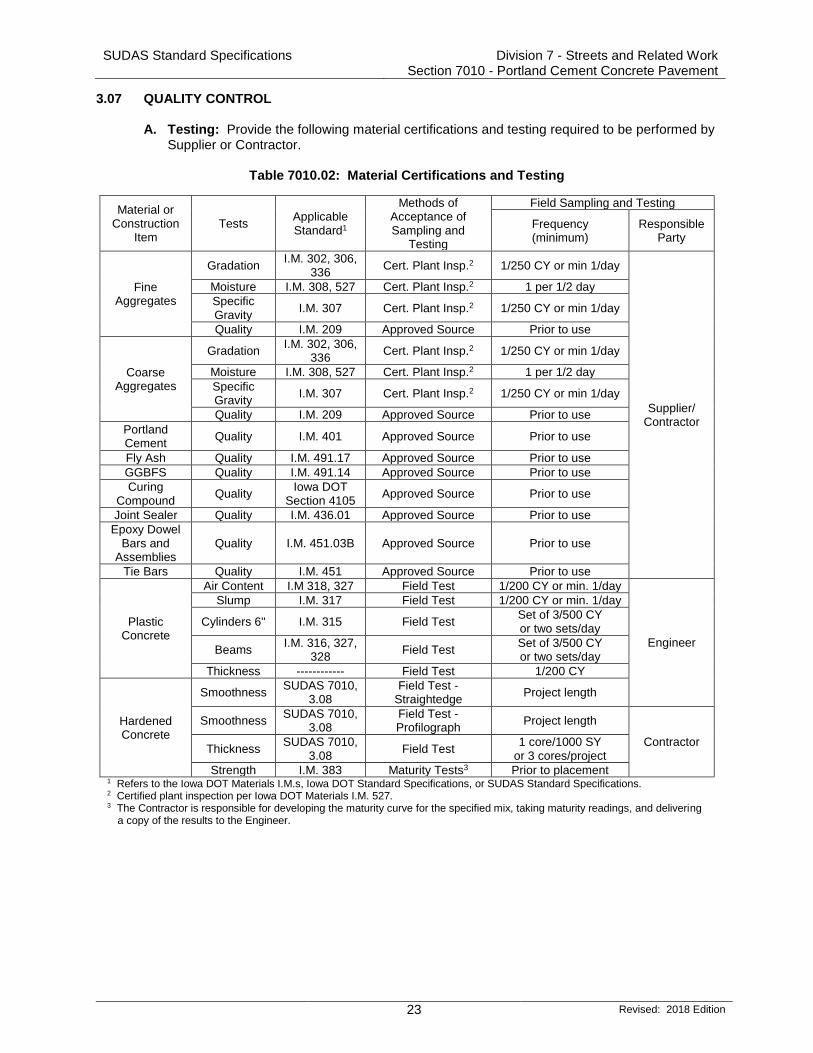
3.07 QUALITY CONTROL A. Testing: Provide the following material certifications and testing required to be performed by
Supplier or Contractor.
Table 7010.02: Material Certifications and Testing
Material or Construction
Item Tests
Applicable Standard1
Methods of Acceptance of Sampling and
Testing
Field Sampling and Testing
Frequency (minimum)
Responsible Party
Fine Aggregates
Gradation I.M. 302, 306,
336 Cert. Plant Insp.2 1/250 CY or min 1/day
Supplier/ Contractor
Moisture I.M. 308, 527 Cert. Plant Insp.2 1 per 1/2 day
Specific Gravity
I.M. 307 Cert. Plant Insp.2 1/250 CY or min 1/day
Quality I.M. 209 Approved Source Prior to use
Coarse Aggregates
Gradation I.M. 302, 306,
336 Cert. Plant Insp.2 1/250 CY or min 1/day
Moisture I.M. 308, 527 Cert. Plant Insp.2 1 per 1/2 day
Specific Gravity
I.M. 307 Cert. Plant Insp.2 1/250 CY or min 1/day
Quality I.M. 209 Approved Source Prior to use
Portland Cement
Quality I.M. 401 Approved Source Prior to use
Fly Ash Quality I.M. 491.17 Approved Source Prior to use
GGBFS Quality I.M. 491.14 Approved Source Prior to use
Curing Compound
Quality Iowa DOT
Section 4105 Approved Source Prior to use
Joint Sealer Quality I.M. 436.01 Approved Source Prior to use
Epoxy Dowel Bars and
Assemblies Quality I.M. 451.03B Approved Source Prior to use
Tie Bars Quality I.M. 451 Approved Source Prior to use
Plastic Concrete
Air Content I.M 318, 327 Field Test 1/200 CY or min. 1/day
Engineer
Slump I.M. 317 Field Test 1/200 CY or min. 1/day
Cylinders 6" I.M. 315 Field Test Set of 3/500 CY or two sets/day
Beams I.M. 316, 327,
328 Field Test
Set of 3/500 CY or two sets/day
Thickness ------------ Field Test 1/200 CY
Hardened Concrete
Smoothness SUDAS 7010,
3.08 Field Test -
Straightedge Project length
Smoothness SUDAS 7010,
3.08 Field Test - Profilograph
Project length
Contractor Thickness
SUDAS 7010, 3.08
Field Test 1 core/1000 SY
or 3 cores/project
Strength I.M. 383 Maturity Tests3 Prior to placement 1 Refers to the Iowa DOT Materials I.M.s, Iowa DOT Standard Specifications, or SUDAS Standard Specifications. 2 Certified plant inspection per Iowa DOT Materials I.M. 527. 3 The Contractor is responsible for developing the maturity curve for the specified mix, taking maturity readings, and delivering
a copy of the results to the Engineer.

SUDAS Standard Specifications Division 7 - Streets and Related Work Section 7010 - Portland Cement Concrete Pavement
24 Revised: 2018 Edition
3.07 QUALITY CONTROL (Continued) B. Air Content:
1. Air content of the concrete will be evaluated according to Iowa DOT Materials I.M. 318
and 327. 2. When a test result is outside the tolerance for the target air content, the contractor will be
notified immediately. An air test will then be immediately run behind the paver to aid in identifying the limits of the non-complying air. A test result between 5% and 8% behind the paver will be considered complying. This test will represent all concrete from the back of the paver back to the last documented complying test. Make immediate adjustments to the mix production and placement process to bring the air content back within tolerance. Do not use succeeding loads below the lower target air content tolerance by more than 0.5%. Each subsequent load will be tested until air content is within tolerance for two consecutive loads. For all incorporated, non-complying concrete that is out of tolerance, the Engineer will determine if removal and replacement is required or if a price adjustment, according to Table 7010.03, will be applied.
Table 7010.03: Concrete Air Content Price Adjustments
Air Content Range % Payment of Unit Price
Minimum Maximum 1.1* and below 0% 0.6 to 1.0* 50% 0.1 to 0.5* 75%
Low air tolerance limit 100% Target 100%
High air tolerance limit 100% 0.1 to 0.5** 95% 0.6 to 1.0** 85% 1.1 to 1.5** 75% 1.6 to 2.0** 60%
2.1** and above 0%
*Air content deviation below the acceptable limits ** Air content deviation above the acceptable limits
C. Pavement Smoothness: Evaluate pavement smoothness for all PCC pavement and overlay
surfaces.
1. Straightedge: The Engineer will check PCC pavement surfaces with a 10 foot straightedge placed parallel to the centerline. Areas showing high spots of more than 1/4 of an inch in 10 feet will be marked. Complete surface corrections according to the procedures in Iowa DOT Section 2316 to an elevation where the area or spot will not show surface deviations in excess of 1/8 inch when tested with a 10 foot straightedge. Surface corrections will be completed at the direction of the Engineer with no additional cost to the Contracting Authority.
2. Profilograph:
a. If specified in the contract documents, comply with Iowa DOT Section 2316 to measure pavement smoothness with a profilograph.
b. Evaluate according to the smoothness requirements of Table 7010.04 and make surface corrections and price reductions. Surface corrections will be completed with no additional cost to the Contracting Authority. No incentive for pavement smoothness will be made.

SUDAS Standard Specifications Division 7 - Streets and Related Work Section 7010 - Portland Cement Concrete Pavement
25 Revised: 2018 Edition
3.07 QUALITY CONTROL (Continued)
Table 7010.04: Pay Factor if Profilograph Used
Segment Index (inch/mile) Pay Factor
0 - 22.0 100%
22.1 - 30.0 97%
30.1 and over Grind as directed by Engineer
c. Smoothness measurements will be suspended for structures and through
intersections.
D. Pavement Thickness:
1. At locations determined by the Engineer, cut samples from the pavement by drilling with a core bit that will provide samples with a 4 inch outside diameter. Restore the surface by tamping low slump concrete into the hole, finishing, and texturing. The Engineer will witness the core drilling, identify, and take possession of the cores. The Engineer will determine the core locations, measure the cores, and determine the thickness index according to Iowa DOT Materials I.M. 346 and 347, except as modified as follows: a. For regular or irregular shaped areas, use a lot size of 1,000 square yards. Include
remnants less than 500 square yards in the last lot and remnants greater than 500 square yards in a separate lot. Take a minimum of three cores per project.
b. For any core with a deficiency greater than 0.15 inch, take two additional cores in that pavement lot and use the average of the three cores.
2. Coring of pavement or other work for thickness determination may be waived by mutual
agreement for sections of the same design thickness less than 2,500 square yards. 3. Based on the thickness index determined by the Engineer, the pavement payment will be
as shown in Tables 7010.05 and 7010.06. 4. If the thickness index deficiency is greater than 0.51 for pavements thinner than 9 inches
or 0.91 for pavements 9 inches or thicker, the Engineer will study the extent and severity of the deficiency of the pavement areas. The Engineer will require one of the following based on a review on the level of deficiency, the amount of the payment penalty, and the estimated reduction in the design life of the deficient pavement: a. Removal and replacement of the deficient areas with pavement complying with the
contract documents at no additional cost to the Contracting Authority. b. Completion of an agreement that provides a combination of an extended guarantee
period and payment penalty and allows the deficient pavement to be left in place.
Table 7010.05: Pay Factor for PCC Pavement for Design Thickness less than 9"
Thickness Index Range Percent Payment
More than 0 to -0.15 100
-0.16 to -0.25 95
-0.26 to -0.50 85
-0.51 or less As determined by the Engineer

SUDAS Standard Specifications Division 7 - Streets and Related Work Section 7010 - Portland Cement Concrete Pavement
26 Revised: 2018 Edition
3.07 QUALITY CONTROL (Continued)
Table 7010.06: Pay Factor for PCC Pavement for Design Thickness 9” or Greater
Thickness Index Range Percent Payment
More than 0.00 to -0.15 100
-0.16 to -0.20 99
-0.21 to -0.25 98
-0.26 to -0.30 97
-0.31 to -0.35 96
-0.36 to -0.40 95
-0.41 to -0.45 94
-0.46 to -0.50 93
-0.51 to -0.55 92
-0.56 to -0.60 91
-0.61 to -0.65 90
-0.66 to -0.70 89
-0.71 to -0.75 88
-0.76 to -0.80 87
-0.81 to -0.85 86
-0.86 to -0.90 85
-0.91 or less As determined by the Engineer
E. Defects or Deficiencies: Remove and replace or repair pavement containing excessive
cracks, fractures, spalls, or other defects at no additional cost to the Contracting Authority. The method of replacement or repair will be determined by the Engineer.
END OF SECTION

This page was intentionally left blank

1
FIG
UR
E 7
010.1
01
See Detail C
5
T
T
T
6
See Detail A or B
See Detail A or B
See Detail A or B
at 12'' Centers
18'' Long Dowel
641
2
30'' Long Tie Bar
at 12'' Centers
2
4
T
30'' Long Tie Bar
at 12'' Centers
743
2
Pavement Edge
15'' min.9'' min.
T
at 12'' Centers.
24'' Long Tie Bar
4
2
Pavement Edge See Detail C
T
Larger than Dowel
''81
Hole Diameter
4 5
at 12'' Centers
18'' Long Dowel
2
9'' min.9'' min.
4 5
Pavement Edge24'' min.
Header Board
Plastic or Tarpaper Wrapped
Header Block2
T/3
2
3
4
6
5
7
SH
EE
T 1 O
F 8
at 12'' Centers
30'' Long Tie Bar
(Abutting Pavement Slabs)
PLAIN JOINT
'B'
(End Rigid Pavement)
HEADER JOINT
'HT'CONTRACTION JOINT
'C'
DOWELED CONTRACTION JOINT
'CD'
ABUTTING PAVEMENT JOINT
'RD'
RIGID TIE
ABUTTING PAVEMENT JOINT
'RT'TIED CONTRACTION JOINT
'CT'
TRANSVERSE CONTRACTION
(Non-working)DAY'S WORK JOINT
'DW'
T
at 12'' Centers
43
Top of Slab
Top of Curb
CURB AND GUTTER UNIT
DAY'S WORK JOINT
'DW - CG'
30'' Long Tie Bar
2
LEGEND
Existing Pavement
Proposed Pavement
Larger than Tie Bar
''81
Hole Diameter
Authority.
the drilling at no additional cost to the Contracting
the days work. Remove any pavement damaged due to
'RT' joint may be used in lieu of 'DW' joint at the end of
less than 8 inches.
greater or equal to 8 inches. Use 'C' joints when T is
contraction joints in mainline pavement when T is
Unless otherwise specified, use 'CD' transverse
placed.
remove header block and board when second slab is
Edge with 1/8 inch tool for length of joint. For HT joint,
assemblies.
Place bars within the limits shown under dowel
'CD' joint.
'C' or 'CD' joints. Place no closer than 5 feet to a 'C' or
Locate 'DW' joint at a mid-panel location between future
See Bar Size Table.
See dowel assemblies for fabrication details.
PV-101
REVISION
10-17-17
SHEET 1 of 8
REVISIONS:standards. Revised notes 22 and 23 on pages 6 and 7 to align with current industry
7
JOINTS
STANDARD PLANROADFIGURE 7010.101
SUDAS DIRECTOR DESIGN METHODS ENGINEER

9
L
TT/2
L/2
FIG
UR
E 7
010.1
01
BAR SIZE TABLE
T
< 8'' #6
#10
#11''211
''43
< 10''
= 8'' but
= 10''
Size
Tie Bar
Diameter
Dowel
''411
8
9
Bottom of Saw Cut
Top of Curb Saw Cut
''211
Top of SlabMaterialJoint Sealant
8
''43" to
21
Top of Pavement
Sealant
'' Saw Cut161'' ±
41
Joint Sealant Material
''81'' ±
41
Saw Cut8
A
A
Joint Line
Crack or
DETAIL C
'' Saw Cut165'' to
81
Joint Sealant Material
''81'' ±
41
''41'' ±
411
Joint Line
Crack or
Joint Sealant Material'' Saw Cut
161'' ±
41
'' Saw Cut41'' ±
411
''81'' ±
41
Joint Line
Crack orA
A
A
A
SH
EE
T 2 O
F 8
of sound PCC.
When tying into old pavement, T represents the depth
depth of T/4 ± 1/4''.
Saw 'CD' joint to a depth of T/3 ± 1/4''; saw 'C' joint to a
(Applies to all joints unless otherwise detailed.)
BAR PLACEMENT
(Saw cut formed by approved early concrete sawing equipment.)
DETAIL B
SECTION A-A
(Detail at Edge of Pavement)
(Saw cut formed by conventional concrete sawing equipment.)
DETAIL A
TRANSVERSE CONTRACTION
(Match 'CT', 'CD', or 'C' joint in pavement.)
'C' JOINT IN CURB
LEGEND
Existing Pavement
Proposed Pavement
PV-101
REVISION
10-17-17
SHEET 2 of 8
REVISIONS:standards. Revised notes 22 and 23 on pages 6 and 7 to align with current industry
7
JOINTS
STANDARD PLANROADFIGURE 7010.101
SUDAS DIRECTOR DESIGN METHODS ENGINEER

FIG
UR
E 7
010.1
01
See Detail C
T
11
12
10
T
< 8'' 24'' Long at 30'' Centers
Joint Bars
'BT-5' #4
#5'BT-3' 24'' Long at 30'' Centers
Bar Length and Spacing
'BT-4' 24'' Long at 15'' Centers= 8''
11
12
T
T
< 8'' 36'' Long at 30'' Centers
Joint Bars
'BT-1' #4
#5'BT-2' 36'' Long at 30'' Centers
Bar Length and Spacing
= 8''
See Detail E
T
T12" Centers
30" Long at
#5 Bars,See Detail E 11
''212
12'' Centers
#5 Bars at
11#5 Bars 30" Long at 12" Centers
#6 Bars at 12'' Centers
#5 Bars at 12'' CentersSee Detail E
''212
''212
12'' Centers
#8 Bars at
12'' Centers
#5 Bars at
10 12
T
< 8'' 30'' Long at 30'' Centers
Joint Bars
'KT-1' #4
#5'KT-2' 30'' Long at 30'' Centers
Bar Length and Spacing
'KT-3' 30'' Long at 15'' Centers= 8''
See Detail E
T
T
T
T
< 8'' 36'' Long at 30'' Centers
Joint Bars
'L-1' #4
#5'L-2' 36'' Long at 30'' Centers
Bar Length and Spacing
'L-3' 36'' Long at 15'' Centers= 8''
12
9'' min. 15'' min.
11
SH
EE
T 3 O
F 8
11
'KT-3' and 'L-3'
'KT-2' and 'L-2'
'BT-1', 'L-1', and 'KT-1'
pouring sequence:
The following joints are interchangeable, subject to the
Sawing or sealing of joint not required.
plastic concrete.
ensure the bar remains in a horizontal position in the
Bar supports may be necessary for fixed form paving to
Joint
'' Dia. Hole for BT-585
and BT-4 Joint
'' Dia. Hole for BT-343
(Abutting Pavement Slabs)
PLAIN JOINT
'B'
[Double Reinforced Pavement (Bridge Approach)]
'KS-2'
ABUTTING PAVEMENT JOINT - RIGID TIE
'BT'
ABUTTING PAVEMENT JOINT - KEYWAY TIE
'KT'
LONGITUDINAL CONTRACTION
(Where T is 8'' or more)
KEYED JOINT FOR ADJACENT SLABS
'K'
[Single Reinforced Pavement (Bridge Approach)]
'KS-1'
(Drilled)ABUTTING PAVEMENT JOINT - RIGID TIE
'BT'
CONTRACTION JOINT'L'
See Detail D-1, D-2, or D-3
See Detail D-1, D-2, or D-3
LEGEND
Existing Pavement
Proposed Pavement
LEGEND
Existing Pavement
Proposed Pavement
PV-101
REVISION
10-17-17
SHEET 3 of 8
REVISIONS:standards. Revised notes 22 and 23 on pages 6 and 7 to align with current industry
7
JOINTS
STANDARD PLANROADFIGURE 7010.101
SUDAS DIRECTOR DESIGN METHODS ENGINEER

FIG
UR
E 7
010.1
01
9
L
TT/2
L/2T/2
A
2''1''
KEYWAY DIMENSIONS
B
Standard
Less than 8''
8'' or greater
Narrow
''431 ''
432
Pavement Thickness TKeyway Type
''81
'' or - 41
1'' +
A B
13
9
DETAIL E
SH
EE
T 4 O
F 8
T
Sealant or cleaning not required.
of sound PCC.
represents the depth When tying into old pavement,
(Applies to all joints unless otherwise detailed.)TIE BAR PLACEMENT
LONGITUDINAL CONTRACTION
Joint Line
Crack or
''41
T/3 ±
Joint Sealant Material'' Saw Cut
161
'' ± 41
DETAIL D-2
specified in the contract documents)
is not the Contracting Authority, or when
(Required when the Department of Transportation
Joint Line
Crack or
''41
T/3 ±
Joint Sealant Material
DETAIL D-3
specified in the contract documents)
is the Contracting Authority, or when
(Required when the Department of Transportation
'' Saw Cut165
'' to 81
Joint Line
Crack or
''41
T/3 ±
'' Saw Cut161
'' ± 81
DETAIL D-1
13
(Required when specified in the contract documents.)
LEGEND
Existing Pavement
Proposed Pavement
LEGEND
Existing Pavement
Proposed Pavement
PV-101
REVISION
10-17-17
SHEET 4 of 8
REVISIONS:standards. Revised notes 22 and 23 on pages 6 and 7 to align with current industry
7
JOINTS
STANDARD PLANROADFIGURE 7010.101
SUDAS DIRECTOR DESIGN METHODS ENGINEER

FIG
UR
E 7
010.1
01
2
14
15
16
17
shovel.
Compact tire buffings by spading with a square-nose
dowel size.
Predrill or preform holes in joint material for appropriate
bars may be cast-in-place.
prevent bond with pavement. At intake locations, dowel
placement limits. Coat the free end of dowel bar to
See Dowel Assemblies for fabrication details and
saw.
formed; edging not required when cut with diamond blade
Edge with 1/4 inch tool for length of joint indicated if
See Bar Size Table.
L
TT/2
L/2
See Detail H
'CF' JOINT
TYPE WIDTH
CF-1 2"
''212
3''
''213
CF-2
CF-3
CF-4
Joint FillerResilientSee Detail F
1'' Nominal
at 12'' Centers
18'' Long Dowel
16
15
(See Doweled Expansion Joints Table)
Width
T
Joints Table)
(See Doweled Expansion
Detail F or Detail G
Top of Curb
Joint Filler
Resilient
1'' Nominalof Slab
Top
2'' Thru Curb
B
B
of Slab
Top
Top of Curb
16
Joint Filler
Flexible Foam
2'' Nominal
B
B
Top of Curb
Top of Slab
1'' Thru Curb
Curb
Joint Filler
Resilient
Slabin Pavement
Match 'E' Joint
B
B
(See Detail F)
Joint Sealant
SECTION B-B
Joint Filler
T
BAR SIZE TABLE
DOWELED EXPANSION JOINTS
EF
16
EE
FILLER MATERIALWIDTHTYPE
ED 1''
2''
''43 ''
411 ''
211
''213
< 8''
Diameter
Dowel
= 10''
'' Joint Sealant Material21
1''
17
Tire Buffings
14
'' 21 3
'' Joint Sealant Material21
''43
Joint Filler
Flexible Foam
16
DETAIL H
DETAIL G
DETAIL F
''85
Filler Joint
Material
'' Joint Sealant21
14
2
14
SH
EE
T 5 O
F 8
< 10''
= 8'' but
for 'EF' joint.
spacer required
pressed wood
" plywood or41
Resilient (Detail F)
Flexible Foam (Detail F)
Flexible Foam (Detail G)
(Applies to all joints unless otherwise detailed.)
DOWEL PLACEMENT
(View at Back of Curb)
JOINT IN CURB
'E'
(View at Back of Curb)
JOINT IN CURB
'EE'
1'' EXPANSION JOINT
'E'
(View at Back of Curb)
JOINT IN CURB
'ES'
DOWELED EXPANSION JOINT
'ED', 'EE', 'EF'
table below)
Width (See
Joints Table)
(See Doweled Expansion
Joint Filler Material
EXPANSION
LEGEND
Existing Pavement
Proposed Pavement
LEGEND
Existing Pavement
Proposed Pavement
PV-101
REVISION
10-17-17
SHEET 5 of 8
REVISIONS:standards. Revised notes 22 and 23 on pages 6 and 7 to align with current industry
7
JOINTS
STANDARD PLANROADFIGURE 7010.101
SUDAS DIRECTOR DESIGN METHODS ENGINEER

DH
Anchor Pins
Pavement
Top of
12'' 12''12''
L
T
12''
Side Rails
Tie WireSide Rails
Tie Wire
Leg
Tie WireTie Wire
12''12''12'' 12''12''
Leg
12''12'' 12''12''
C Contraction Joint and Assembly
FIG
UR
E 7
010.1
01
'' for 12'-0'' Pavement21
'' for 14'-0'' Pavement 11'-0'' ± 21
13'-0'' ±
21 21 21 21 21 21 21
PLAN
ELEVATION
21
232223 23
'' allowable tolerance.41
Spaces between dowel bars are nominal dimensions with a
2222
18
19
20
21
22
23
24
25
DOWEL HEIGHT AND DIAMETER
DiameterDHT 24
''43
''411
''211
''21112'' to 13''
''2110'' to 11
''218'' to 9
''217'' to 7 ''
213
''414
''415
''416
25
24
22
23
LONGITUDINAL SECTION
18 19 20
SH
EE
T 6 O
F 8
Sides
Both
'' min.85
DOWEL ASSEMBLIES
CONTRACTION JOINTS
26
26
26
30
30
of basket to end of basket.
has no more than 1/4 inch horizontal skew from end
inches of the intended joint location longitudinally and
Ensure dowel basket assembly centerline is within 2
jointing layout. See PV-101, sheet 8.
pavements, the assembly length is based on the
If dowel basket assemblies are required for curbed
approved by the Engineer.
placed on pavement or PCC base with devices
assembly during construction. Anchor assemblies
evenly spaced (4 per side), to prevent movement of
Per lane width, install a minimum of 8 anchor pins
of lower side rail + 1/4 inch.
Measured from the centerline of dowel bar to bottom
fit to upper side rail, both sides.
Maximum 0.177 inch diameter wire, welded or friction
minimum required.
0.306 inch diameter wire. Wire sizes shown are the
Weld alternately throughout.
expansion joints.
Details apply to both transverse contraction and
Use wires with a minimum tensile strength of 50 ksi.
1/8 inch.
parallel to the other dowels in the assembly within ±
inch. Ensure the centerlines of individual dowels are
Use 18 inch long dowel bars with a tolerance of ± 1/8
PV-101
REVISION
10-17-17
SHEET 6 of 8
REVISIONS:standards. Revised notes 22 and 23 on pages 6 and 7 to align with current industry
7
JOINTS
STANDARD PLANROADFIGURE 7010.101
SUDAS DIRECTOR DESIGN METHODS ENGINEER

12''12'' 12''12''12''12'' 12''12''12''12''12'' 12''12''
X
Anchor Pins
L
Retainer Rails
Retainer Rails
Leg
Tie WireTie Wire
Retainer Rail
Side Rails
Tie Wire
Leg
Side Rails
DH
T
X
4''
Pavement
Top of
Wire
TieTube
Expansion
Approved
C Expansion Joint and Assembly
FIG
UR
E 7
010.1
01
21
23
21 21 21 21 21 21
23
21
22
23
'' for 12'-0'' Pavement21
'' for 14'-0'' Pavement 11'-0'' ± 21
13'-0'' ±
PLAN
'' allowable tolerance.41Spaces between dowel bars are nominal dimensions with a
ELEVATION
22 22
2225
24
Sides
Both
'' min.85
23
SECTION THRU EXPANSION JOINT
9''
7''
''EF''
6''
2''''EE''
XJoint Type
1''''ED''
18 19 20
DOWEL HEIGHT AND DIAMETER
DiameterDHT 24
''43
''411
''211
''21112'' to 13''
''2110'' to 11
''218'' to 9
''217'' to 7 ''
213
''414
''415
''416
18
19
20
21
22
23
24
25
26
27
SH
EE
T 7 O
F 8
Tube Length
Minimum
DOWEL ASSEMBLIES
EXPANSION TUBE EXTENSION
JOINT OPENING AND
28
26
26
28
272727
28
28
EXPANSION JOINTS
''21
3
30
30
of basket to end of basket.
has no more than 1/4 inch horizontal skew from end
inches of the intended joint location longitudinally and
Ensure dowel basket assembly centerline is within 2
1/4 inch diameter wire.
assembly.
Clip and remove center portion of tie during field
jointing layout. See PV-101, sheet 8.
pavements, the assembly length is based on the
If dowel basket assemblies are required for curbed
approved by the Engineer.
placed on pavement or PCC base with devices
assembly during construction. Anchor assemblies
evenly spaced (4 per side), to prevent movement of
Per lane width, install a minimum of 8 anchor pins
of lower side rail + 1/4 inch.
Measured from the centerline of dowel bar to bottom
fit to upper side rail, both sides.
Maximum 0.177 inch diameter wire, welded or friction
minimum required.
0.306 inch diameter wire. Wire sizes shown are the
Weld alternately throughout.
expansion joints.
Details apply to both transverse contraction and
Use wires with a minimum tensile strength of 50 ksi.
1/8 inch.
parallel to the other dowels in the assembly within ±
inch. Ensure the centerlines of individual dowels are
Use 18 inch long dowel bars with a tolerance of ± 1/8
PV-101
REVISION
10-17-17
SHEET 7 of 8
REVISIONS:standards. Revised notes 22 and 23 on pages 6 and 7 to align with current industry
7
JOINTS
STANDARD PLANROADFIGURE 7010.101
SUDAS DIRECTOR DESIGN METHODS ENGINEER

FIG
UR
E 7
010.1
01
OPTIONAL LEG SHAPES
(0.306" diameter)
#1/0 Gauge Wire
Anchor Pin
2''1'' min.
12'' min.
45°
ANCHOR PIN
18
19
20
18 19 20
SH
EE
T 8 O
F 8
DOWEL ASSEMBLIES
29
29
Back of Curb
Top of Pavement
6''
Longitudinal Joint
2'-0"
Back of Curb
(Curb and Gutter - Gutterline Jointing)
PLACEMENT LIMITS
(Rural Section)
PLACEMENT LIMITS
Longitudinal Joint
1/4 or 1/3 Point
(Curb and Gutter - 1/4 or 1/3 Point Jointing)
PLACEMENT LIMITS
Edge of Pavement Gutterline JointCenterline Joint
6''
31
31
D
BEND AROUND DOWEL29
" max.163
D +
31
31
width pavements: 3" - 12".
For uniform lane widths: 3" - 6". For taper and variable
to 3/16 inches.
Diameter of bend around dowel is dowel diameter + 1/8
expansion joints.
Details apply to both transverse contraction and
Use wires with a minimum tensile strength of 50 ksi.
inch.
parallel to the other dowels in the assembly within ± 1/8
inch. Ensure the centerlines of individual dowels are
Use 18 inch long dowel bars with a tolerance of ± 1/8
PV-101
REVISION
10-17-17
SHEET 8 of 8
REVISIONS:standards. Revised notes 22 and 23 on pages 6 and 7 to align with current industry
7
JOINTS
STANDARD PLANROADFIGURE 7010.101
SUDAS DIRECTOR DESIGN METHODS ENGINEER


5’-0"
1
22
2
12
1
Joint
Longitudinal
Joint
Longitudinal
1
33
1
Joint
Longitudinal
AT JOINT INTERSECTION OFFSET AT JOINT INTERSECTION
CIRCULAR AT A SINGLE JOINT
1
2
3
PV-103STANDARD PLANROAD
REVISION
New
REVISIONS:
SHEET 1 of 1
SUDAS DIRECTOR DESIGN METHODS ENGINEER
SECTION A-A
Adjustment Ring
PCC Pavement
Adjustment Ring
PavementPCC
2 3 2 3
2 3 2 3
A
A 1
2
2
2
21
A A
AA
A
A
FIGURE 7010.103
FIG
UR
E 7
010.1
03
SH
EE
T 1 O
F 1
(For three-piece floating casting)
4
4
5’-0"
5’-0"
5’-0"
120
5’-0"
6" 6"
5’-0"
6"6"
SECTION A-A
(For two-piece fixed casting)
PCC PAVEMENT
MANHOLE BOXOUTS IN
Joint
’C’ or ’CD’
Joint
’C’ or ’CD’
Joint
’C’ or ’CD’
’E’ Joint’E’ Joint
’BT-2’ Joint’BT-1’, or’KT-1’, ’KT-2’,
’BT-2’ Joint’BT-1’, or’KT-1’, ’KT-2’,
reinforcement. Center casting within boxout area.
pavement class. Minimum 2 inches clear on
Construct boxout with Class C concrete or match
04-19-11
New. Joint Standard with SUDAS.
in Section A-A for three-piece floating casting.
is used with a three-piece casting, construct as detailed
(SW 601 Type B and D or SW-602 Type F). If a boxout
No boxout is required for three-piece floating castings
#4 hoops (variable length). Place at mid-slab.
4 foot 8 inch (typ.) #4 bar. Place at mid-slab.
and C or SW-602 Type E) is used.
used. ’E’ joint if two-piece fixed casting (SW 601 Type A
casting (SW 601 Type B and D or SW-602 Type F) is
’KT-1’, ’KT-2’, ’BT-1’, or ’BT-2’ joint if three-piece floating


SH
EE
T 1 O
F 1
STANDARD PLANROADFIGURE 7010.104
REVISION
New
REVISIONS:
SHEET 1 of 1
SUDAS DIRECTOR DESIGN METHODS ENGINEER
PV-104
RAMPED MEDIAN NOSE
FIG
UR
E 7
010.1
04
be at the begining of the rounded median.
When X or Y is 4 feet or greater the expansion joints will
roadway pavement quantities.
Quantities for ramped median nose area is included in
Special shaping of curb.
’RD’ joint.
’C’ Joint. If boxout length is greater than 12 feet, provide
If boxout length is less than or equal to 12 feet, provide
end of normal curb.
’E’Joint. If median is paved, place expansion joints at the
curb.
’EE’ Joint. Expansion joints located at the end of normal
For details of paved median, see contract documents.1
2
3
4
5
6
7
DETAIL A
SECTION A-A
"812
1
Y = W/2 + 12’’
X = W/2 + 7.5’’
W = Width from back of curb to back of curb
’RD’ Joint
RAMPED MEDIAN NOSE
(Median Width 8’-0" or Less)
PLAN6’’ STANDARD
PLAN6’’ SLOPED
New. Previously page 2 of PV-2.
04-19-11
4’-0"
16
4
pavement jointing.Match adjacent
Back of Curb
Y
Boxout Limits(varies)
’E’ Joint
Back of Curb
W
12" Hole forSign Post(if required)
10:1
Slope
72
2
3
A A
"411
6
3 See Detail ’A’
SurfaceRoadway
MedianTop of
12" Hole for Sign Post(if required)
SurfaceRoadway
pavement jointing.
Match adjacent
5
’E’ Joint
Back of Curb
1
6
’E’ Joint
Back of Curb
W
12" Hole forSign Post(if required)
’E’ Joint
Boxout Limits(varies)
’RD’ Joint
pavement jointing.
Match adjacent
4’-0"
10:1
Slope
2
5
2
7
4
3
A A
pavement jointing.
Match adjacent
X


STANDARD PLANROAD
REVISION
REVISIONS:
SUDAS DIRECTOR DESIGN METHODS ENGINEER
04-21-15
PV-101
Maximum 20'
'C' or 'C
D'
'C' or 'C
D'
'C' or 'C
D'
'C' or 'C
D'
'C' or 'C
D'
'C' or 'C
D'
Cracks
'C' or 'C
D'
'C' or 'C
D'
No Joint
'C' or 'C
D'
'C' or 'C
D'
'C' or 'C
D'
PV-101.For joint details, see
SHEET 1 of 1
SH
EE
T 1 O
F 1
FIG
UR
E 7
010.1
21
Possible Curb
Possible Curb
PV-102.For curb details, see PV-102
'ED'
'ED'
Min. 5'
15' Typical
15' Typical
(PCC)or 'CD' JointExisting 'C'
Joint (PCC)ExpansionExisting
1
1
Less than 5'
midpoint.If more than 20 feet, add extra joint at
PV-121
PCC Widening
PCC Widening
Existing Pavement
JOINTING PCC PAVEMENT WIDENING
FIGURE 7010.121
intermediate cuts.
joints first, then make
Cut joints opposite existing
2 'BT' Joint.
2
2
1
new version.
Added circle note 2 and replaced the DOT logo in the title block with the


SUDAS Standard Specifications
REVISION
10-16-12
SHEET 1 of 1
7010.901
PCC PAVEMENT JOINTING
Joint Type
Transverse
Joint Spacing
Transverse
Thickness
Pavement
CD
CD
15'
20'5
TRANSVERSE JOINT REQUIREMENTS
3
2 22
2
3
2
22
3
2
Profile Grade
2.0%
QUARTER POINT JOINTING
THIRD POINT JOINTING
GUTTERLINE JOINTING
6'-6"
8'-0"
6'-6"
7'-6"
6'-6"
7'-6"
6'-6"
8'-0"
26' Back to Back
31' Back to Back
26' Back to Back
31' Back to Back
26' Back to Back
31' Back to Back
10'-0"
12'-6"
8'-6"
10'-6"
1
Profile Grade
Profile Grade
10'-0''
12'-6''
9'-0''
10'-0''
FIG
UR
E 7
010.9
01
SH
EE
T 1 O
F 1
2.0%1
1
1
1
1
8'-6"
10'-6"
2.0% 2.0%
2.0% 2.0%
5
4
3
2
1
4
C
C
CD
12'
15'
15'
5
5
6"
7"
8"
9"
=10"
3'-0'' 3'-0"
2'-0" 2'-0"
2'-0"2'-0"
2'-0" 2'-0"
5
5
5
1
See Figure 7010.101, Sheet 8.
first dowel 6 inches from the joint.
curb. With gutterline joint, place
No dowels within 24" of the back of
contract documents.
Unless otherwise specified in the
Subbase or subgrade as specified.
staging.
pavement thickness and construction
BT, KT, or L joint depending on
6 inch standard curb.


1/8" High
HMA
Overlay Thickness
TYPICAL SECTION
REVISION
10-15-13
SHEET 1 of 1
7010.902
PCC PAVEMENT WIDENING
1'-6"
FIG
UR
E 7
010.9
02
SH
EE
T 1 O
F 1
Widening Width as Specified
Cross Slope as Specified
Specified
1'-0" or as
TPavement
Existing
2'-0"
T
2'-6"
1
CURB FOR WIDENING WITH HMA OVERLAY
See Figure 7010.102
Integral Curb as Specified.
See Figure 7010.121 for typical joint layout.
See Figure 7010.102.
Integral Curb as Specified. saw cut.
Remove existing curb using full depth
specified.
Subgrade or subbase material as
documents.
as specified in the contract
Match existing pavement thickness or
3
2
1
BT-5 Joint
BT-3 or
1
2
3
2" Thickened Edge
SUDAS Standard Specifications


in approach.
terminate curb
If applicable,
DW Joint
Rail
Tie
2
3
6
5
4
2" min. clear
~ Stabilized Subgrade ~
~ Ballast ~
~ HMA ~~ PCC ~
7
By RailroadC of TracksL
By Railroad
Angle of Crossing
REVISION
SHEET 1 of 1
7010.903
1
2
3
4
SECTION A-A
PLAN VIEW - STRAIGHT CROSSING
7
HMA
DW Joint
C of RoadwayL
C of TracksL
Tracks
8
Sidewalk
1
2
3
4
7
HMA
DW Joint
C of TracksL
C of RoadwayL
8
Sidewalk
6"
5'-0" 3'-0" min.
6"
T+4"T
T/2
5'-6" 5'-6"
Varies
AAAA
6"min.
3'-0"
min.
3'-0"
STATION
LOCATION
STATION
LOCATION
8
7
6
5
4
3
2
1PCC Approach
5'-6"
12"
12"
Board
1" Fiber
Porous Backfill Material
FIG
UR
E 7
010.9
03
SH
EE
T 1 O
F 1
PLAN VIEW - SKEWED CROSSINGCROSSING APPROACH
PCC RAILROAD
warning location.
Refer to Figure 7030.205 for detectable
HMA full depth patch per Section 7040.
level to 1/2 inch below top of rail.
existing crossings, construct pavement
inch to 1 inch below top of rail. For
For new crossings, construct pavement 1/2
ballast meeting railroad specifications.
Granular subbase, modified subbase, or
DOT Materials I.M. 443.01.
specified. Include rodent guard per Iowa
Install 6 inch perforated CMP subdrain, if
#5 bars X (approach width minus 4 inches).
center.
length minus 4 inches, at 12 inches on
5 foot 2 inch (typ.) #5 bar or pavement
when necessary and tie securely.
reinforcing bars a minimum of 12 inches
intersections with other bars. Lap
Tie reinforcing bars with wire at all
2 10-20-15
SUDAS Standard Specifications


FIG
UR
E 7
010.9
04
SH
EE
T 1 O
F 1
REVISION
10-19-10New
SHEET 1 of 1
7010.904
49'
31'
Normal Spacing
Normal Spacing
'C'
R
'L'
'C'
'C'
'C'
'L' or 'K
T'
'L'
1/2 Normal 'C' Spacing
Boxout with 'KT'
'L'
'C'
1/2 Normal 'C' Spacing
R
2' Min.
R
26' or 31'
1
2'HT'3
3
3
26' or 31'
2' Min.
'KT' or 'L' Joint
'L' Joint
'L' Joint
Driveway
Future
Driveway
Commercial
'KT' or 'L' Joint
'KT' or 'L' Joint
'KT' or 'L' Joint
'KT' Joint
'L' or 'KT' Joint
Day's Work
End of
'DW'
Day's Work
End of
'DW'
'C' Joint
'E' Joint
'KT' Joint
'C' Joint
'KT' Joint
'KT' Joint
'C' Joint
'L' Joint
3
2
1
intersections.
additional 'C' joint at radius
When radius exceed 20 feet, add one
joint.
street, terminate with a type 'HT'
Where pavement abuts an unimproved
intake boxouts.
round castings and fall at the edges of
of openings to allow joints to intersect
Shorten jointing pattern on either side
TYPICAL JOINTING LAYOUT
'BT', 'RT', or 'RD' joint.
keyed joints are present, provide a
and no existing dowels, tie bars, or
Where new and existing pavements meet,
transverse joint spacing.
Refer to Figure 7010.901 for maximum
PLAN VIEW
SUDAS Standard Specifications

'L-1'
'RD'
6.5'
6.5'
6.5'
6.5'
6.5'
6.5'
6.5'
6.5'
'RD'
'KT'
'L'
45' R
9.5' 13'
12'10'
'C'
'C'
'C'
'C'
'C'
'C'
12'
11'11'12'12'11'11'
'C'
11'
11'
10'
'C'
'C'
10'
'C'
9.5' 13'
13'
13' 9.5'9.5' 13' 13.1'
'C'
'C'
'C'
'C'
'C'
'C'
'C'
'C'
'C'
'C'
'C'
15' 15'
11'
11'
10'
10'
11'
11'
11'
11'
'C'
11' 15'
'C'
11'
'L'
'L'
'L'
'L'
'L'
'L'
'L'
'KT'
'KT''KT'
'KT'
45' R
'C'
'C'
2' min.
FIG
UR
E 7
010.9
05
SH
EE
T 1 O
F 3
'L'
'L'
'L'
'KT'
'L'
'L'
'L'
'L'
'L'
2' min.
'L'
50' R
<70
<70
50' R
'RD'
>70
REVISION
New 10-19-10
7010.905SHEET 1 of 3
DETAIL A
DETAIL B
DETAIL C
PCC CUL-DE-SAC JOINT LOCATIONS
See Detail A
See Detail A
See Detail B
See Detail C
See Detail C
QUARTER POINT JOINTING
SUDAS Standard Specifications

FIG
UR
E 7
010.9
05
SH
EE
T 2 O
F 3
6.5'
9.0'
8.5'
8.5'
9.0'
8.5'
45' R
45' R
10'
11'
11'
'C'
'C'
'C'
11'
12'
'C'
'C'
'C'
'C'
'C'
'C'
'C'
'C'
'C'
'C'
'C'
'C'
'C'
'C'
'C'
'C'
10'
11'
10'
11'
11'
11'
'C'
9.5' 13' 13' 13' 13' 9.5'9.5'
'C'
'C'
9'
'C'
'C'
'L'
'L'
'L'
'L'
'L'
'L'
'L'
'L'
'L'
'L'
'L'
'L'
'L'
'L'
'L'
'L'
'L'
'KT'
'KT''KT'
'KT'
'KT''KT'
12'
11' 11' 11' 12' 12' 12' 11'
10' 11' 11' 11' 15'
'RD'
50' R
50' R
'RD'
'RD'
REVISION
New 10-19-10
7010.905SHEET 2 of 3
PCC CUL-DE-SAC JOINT LOCATIONS
See Detail A
See Detail B
See Detail A
See Detail B
See Detail C
THIRD POINT JOINTING
SUDAS Standard Specifications

FIG
UR
E 7
010.9
05
SH
EE
T 3 O
F 3
REVISION
New 10-19-10
SHEET 3 of 3
PCC CUL-DE-SAC JOINT LOCATIONSGUTTERLINE JOINTING
7010.905
45' R
45' R
9.5' 13' 13' 13' 13'
13'
11'
11'
10'
13'
10'
11'
12'
9.5' 9.5'9.5' 13' 13.1'
10'
13'
10'
11'
11'
15' 15'
'C'
'C'
'C'
'C'
'C'
'C'
'C'
'C'
'C'
'C'
'C'
'C'
9'
11'
11'
10' 10' 12' 13' 12' 12' 12'
11' 10' 11' 11' 11'15'
'C'
'C'
'C'
'C'
'C'
'C'
'C'
'C'
'C'
'C'
'C'
'C'
'L'
'L'
'L'
'L'
'L'
'L'
'L'
'L'
'L'
'L'
'L'
'KT'
'KT'
'KT'
'KT'
'KT''KT'
10'
10'
'RD'
'RD'
'RD''L'
'L'
50' R
50' R
3'
3'
10'
10'
3'
3'
See Detail A
See Detail B
See Detail A
See Detail B
See Detail C
SUDAS Standard Specifications

REVISION
SHEET 1 of 1
7010.906
10-19-10
FIG
UR
E 7
010.9
06
SH
EE
T 1 O
F 1
#4 Deformed Bar
2
1
Seal all joints.
joints with 1 inch expansion material.
the Engineer. Construct expansion
Install expansion joints as directed by
pattern of the existing pavement.
spacing of 15'. Match the joint
Construct 'C' joints at a maximum
contract documents.
Median height as specified in the
4"
10"
Overlay
Possible
5"
pavement 1/2".
Mill existing
DOWELED MEDIAN
DOWEL BAR DETAIL
1
2
Pavement
Existing
Removal Line4% Cross Slope (or as specified)
New Pavement
in the contract documents.
Width of island as specified
with Existing Pavement
Typical Half Section
with New Pavement
Typical Half Section
LANDSCAPE MEDIAN
MEDIANS
in the contract documents.
Width of island as specified
Surface
Pavement
Existing
8" typ.
as specified.
Cross slope 1 1/2" typ.
Grass or Landscaping (as specified)
Concrete
polymer grout.
for dowel bars and install with
spacing. Drill holes in existing slab
Dowel bars at 24" C-C longitudinal
or BT-5 Joint
Install BT-3, BT-4,
New
SUDAS Standard Specifications