SECTION 7 - SUSPENSION - mymowerparts.com Arctic Cat Discount Parts Call 606-678-9623 or 606-561 ......
10
7-1 7 SECTION 7 - SUSPENSION TABLE OF CONTENTS Front and Rear Suspension Assembly Schematics........................................................... 7-2 Shock Absorbers ..................................................... 7-3 Front A-Arms ........................................................... 7-4 Rear A-Arms ........................................................... 7-7 Wheels and Tires .................................................... 7-9 For Arctic Cat Discount Parts Call 606-678-9623 or 606-561-4983 www.mymowerparts.com
Transcript of SECTION 7 - SUSPENSION - mymowerparts.com Arctic Cat Discount Parts Call 606-678-9623 or 606-561 ......

7-1
7
SECTION 7 - SUSPENSION
TABLE OFCONTENTS
Front and Rear Suspension Assembly Schematics........................................................... 7-2Shock Absorbers ..................................................... 7-3Front A-Arms........................................................... 7-4Rear A-Arms ........................................................... 7-7Wheels and Tires .................................................... 7-9
For Arctic Cat Discount Parts Call 606-678-9623 or 606-561-4983
www.mymowerparts.com

7-2
Front and Rear Suspension Assembly
Schematics
0739-292
0739-056
KEY1. Retainer2. Shock Absorber3. Bushing4. Sleeve5. Adjuster Cam6. Spring7. Cap Screw8. Lock Nut9. A-Arm Assy
10. Bushing11. Collar12. Ball Joint Clip13. Ball Joint14. A-Arm15. Bushing16. Collar17. Knuckle Assy18. Seal
19. Bearing Clip20. Wheel Hub Bearing21. Knuckle22. Seal23. Cap Screw24. Drive Axle25. Clip26. Boot Repair Kit27. Cap Screw28. Cap Screw29. Boot Guard30. Body Screw
FRONT31. Spanner Wrench32. A-Arm Brace33. Cap Screw
REARKEY1. Knuckle Assy2. Knuckle3. Bearing4. Retaining Ring5. Collar6. Bushing7. Cap Screw8. Lock Nut9. A-Arm
10. Bushing 11. Collar
12. A-Arm13. Cap Screw14. Drive Axle15. Clip16. Boot Repair Kit17. Boot Guard18. Body Screw19. Boot Guard20. Shock Absorber21. Bushing22. Sleeve23. Adjuster Cam24. Retainer25. Spring26. Cap Screw27. Washer28. Cap Screw29. Spanner Wrench
7-3
7
Shock Absorbers
REMOVING
1. Secure the ATV on a support stand to elevate thewheels and to release load on the suspension.
2. Remove the two cap screws and nuts securingeach front shock absorber to the frame. Accountfor bushings and sleeves from each.
AF605D
3. Remove the two cap screws and nut securing eachrear shock absorber to the frame and rearsuspension. Account for bushings and sleevesfrom each.
AF626D
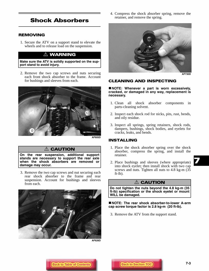
4. Compress the shock absorber spring, remove theretainer, and remove the spring.
AF730D
CLEANING AND INSPECTING
NOTE: Whenever a part is worn excessively,cracked, or damaged in any way, replacement isnecessary.
1. Clean all shock absorber components inparts-cleaning solvent.
2. Inspect each shock rod for nicks, pits, rust, bends,and oily residue.
3. Inspect all springs, spring retainers, shock rods,dampers, bushings, shock bodies, and eyelets forcracks, leaks, and bends.
INSTALLING
1. Place the shock absorber spring over the shockabsorber, compress the spring, and install theretainer.
2. Place bushings and sleeves (where appropriate)into shock eyelet; then install shock with two capscrews and nuts. Tighten all nuts to 4.8 kg-m (35ft-lb).
NOTE: The rear shock absorber-to-lower A-armcap screw torque factor is 2.8 kg-m (20 ft-lb).
3. Remove the ATV from the support stand.
! WARNING
Make sure the ATV is solidly supported on the sup-port stand to avoid injury.
! CAUTIONOn the rear suspension, additional supportstands are necessary to support the rear axlewhen the shock absorbers are removed ordamage may occur.
! CAUTIONDo not tighten the nuts beyond the 4.8 kg-m (35ft-lb) specification or the shock eyelet or mountWILL be damaged.

7-4
Front A-Arms
REMOVING
1. Secure the ATV on a support stand to elevate thewheel; then remove the wheel.
2. Remove the wheel cap from the hub; then removethe cotter pin from the nut.
KX041
3. Remove the nut securing the hub. Account for awasher.
4. Remove the brake caliper.
CD007
5. Remove the hub assembly.
6. Remove the cotter pin and slotted nut securing thetie rod end to the knuckle; then remove the tie rodend from the knuckle.
AF618D
7. Remove the cap screws securing the ball joints tothe knuckle.
AF628D
8. Tap the ball joints out of the knuckle; then removethe knuckle.
9. Remove the lower shock absorber eyelet from theupper A-arm.
AF626D
10. Remove the cap screws securing the A-arms to theframe.
! WARNING
Make sure the ATV is solidly supported on the sup-port stand to avoid injury.

7-5
7
AF610D
11. Remove the circlip from the ball joint; thenremove the ball joint from the A-arm.
AF616D
CLEANING AND INSPECTING
NOTE: Whenever a part is worn excessively,cracked, or damaged in any way, replacement isnecessary.
1. Clean all A-arm components in parts-cleaningsolvent.
2. Clean the ball joint mounting hole of all residualLoctite, grease, oil, or dirt for installing purposes.
3. Inspect the A-arm for bends, cracks, and wornbushings.
4. Inspect the ball joint mounting holes for cracks ordamage.
5. Inspect the frame mounts for signs of damage,wear, or weldment damage.
INSTALLING
1. Apply green Loctite #609 to the entire outsidediameter of the ball joint; then install the ball jointinto the A-arm and secure with the circlip.
AF616D
2. Install the A-arm assemblies into the framemounts and secure with the cap screws. Onlyfinger-tighten at this time.
AF610D
3. Route the brake hose through the upper A-armshock absorber mount.
AF627D
4. Secure the lower eyelet of the shock absorber tothe upper A-arm. Tighten nut to 4.8 kg-m (35ft-lb).
5. Secure the A-arm assemblies to the frame mounts(from step 2). Tighten the cap screws to 4.8 kg-m(35 ft-lb).
! CAUTIONDo not tighten the nut beyond the 4.8 kg-m (35ft-lb) specification or the shock eyelet or mountWILL be damaged.

7-6
6. Install the knuckle assembly onto the ball jointsand secure with cap screws. Tighten to 4.8 kg-m(35 ft-lb).
AF628D
7. Install the tie rod end and secure with the nut.Tighten to 4.2 kg-m (30 ft-lb); then install a newcotter pin and spread the pin to secure the nut.
NOTE: During assembly, new cotter pins shouldbe installed.
AF618D
8. Apply grease to hub sealing area and on the driveaxle splines; then install the hub assembly onto thedrive axle.
CD009
9. Place the washer onto the shaft; then secure thehub assembly with the nut. Tighten only untilsnug.
10. Secure the brake caliper to the knuckle with thetwo cap screws. Tighten to 2.8 kg-m (20 ft-lb).
CD007
11. Secure the hub nut (from step 10) to the shaft/axle.Tighten to 10.4 kg-m (75 ft-lb).
12. Install a new cotter pin and spread the pin tosecure the nut.
KX041
13. Install the wheel cap.
14. Install the wheel and tighten to 5.5 kg-m (40 ft-lb).
CD006
15. Remove the ATV from the support stand.

7-7
7
Rear A-Arms
REMOVING
1. Secure the ATV on a support stand to elevate thewheels.
2. Pump up the hand brake; then engage the brakelever lock.
3. Remove the wheel and rubber wheel cap.
4. Remove the cotter pin securing the hex nut; thenremove the hex nut and washer. Release the brakelever lock.
KX041
5. Remove the two brake calipers (right side only).
NOTE: Do not allow the brake calipers to hangfrom their cable/hose.
6. Remove the cap screws and lock nut securing theshock absorber to the frame and lower A-arm; thenremove the shock absorber.
7. Remove the cap screws securing the boot guard tothe lower A-arm.
AF934
8. Slide the hub out of the knuckle and set aside.
9. Remove the cap screws and lock nuts securing theknuckle to the A-arms. Discard the lock nuts.
AF936
NOTE: Never reuse a lock nut. Once a lock nuthas been removed, it must be replaced with a newlock nut.
10. Remove the cap screws and lock nuts securing theA-arms to the frame; then remove the A-arms.
NOTE: If removing the upper right A-arm, it willbe necessary to disconnect the brake hose andbrake cable from the A-arm.
CLEANING AND INSPECTING
NOTE: Whenever a part is worn excessively,cracked, or damaged in any way, replacement isnecessary.
1. Clean all A-arm components in parts-cleaningsolvent.
2. Inspect the A-arm for bends, cracks, and wornbushings.
3. Inspect the frame mounts for signs of damage,wear, or weldment damage.
INSTALLING
1. Install the A-arm assemblies into the framemounts and secure with the cap screws and newlock nuts. Only finger-tighten at this time.
! WARNING
Make sure the ATV is solidly supported on the sup-port stand to avoid injury.

7-8
2. Slide the knuckle onto the drive axle and intoposition on the A-arms; then secure the knuckle tothe A-arms with cap screws and new lock nuts.Tighten to 4.8 kg-m (35 ft-lb).
3. Tighten the hardware securing the A-arms to theframe mounts (from step 1) to 4.8 kg-m (35 ft-lb).
4. Apply grease to hub sealing area and on the driveaxle splines; then install the hub assembly onto thedrive axle.
CD009
5. Place the washer onto the drive axle; then securethe hub assembly with the nut. Tighten only untilsnug.
6. Secure the brake caliper to the knuckle with thetwo cap screws (right side only). Tighten thehydraulic caliper to 2.8 kg-m (20 ft-lb).
NOTE: Ensure that the brake hose and brakecable are properly routed and secured to the upperA-arm.
CD007
7. Secure the hub nut (from step 6) to the drive axle.Tighten to 17.5 kg-m (125 ft-lb).
8. Install a new cotter pin and spread the pin tosecure the nut.
KX041
9. Secure the shock absorber to the frame with a capscrew and new lock nut. Tighten to 4.8 kg-m (35ft-lb).
10. Secure the shock absorber to the lower A-arm witha cap screw and new lock nut. Tighten to 2.8 kg-m(20 ft-lb).
11. Secure the boot guard to the lower A-arm with thetwo cap screws. Tighten securely.
12. Install the wheel cap.
13. Install the wheel and tighten to 5.5 kg-m (40 ft-lb).
14. Remove the ATV from the support stand.

7-9
7
Wheels and Tires
0739-058
TIRE SIZE
The ATV is equipped with low-pressure tubeless tiresof the size and type listed below. Do not under any cir-cumstances substitute tires of a different type or size.
TIRE INFLATION PRESSURE
Front and rear tire inflation pressure should be 0.35kg/cm² (5.0 psi).
REMOVING
1. Secure the ATV on a support stand to elevate thewheels.
2. Remove the wheels.
NOTE: Keep left-side and right-side wheels sep-arated for installing them on their proper sides.
CD006
KEY1. Machine Screw2. Brake Disc3. Wheel Hub - Front4. Hub Stud5. Hub Seal6. Castle Nut7. Cotter Pin8. Wheel9. Tire - Front
10. Mounting Nut11. Valve Stem12. Valve Stem Cap13. Wheel Hub - Rear14. Wheel15. Tire - Rear
! WARNING
Use only Arctic Cat approved tires when replacingtires. Failure to do so could result in unstable ATVoperation.
! WARNING
Do not mix tire tread patterns. Use the same patterntype on front and rear. Failure to heed warningcould cause poor handling qualities of the ATV andcould cause excessive drive train damage not cov-ered by warranty.
! WARNING
Make sure the ATV is solidly supported on the sup-port stand to avoid injury.

7-10
CLEANING AND INSPECTING
NOTE: Whenever a part is worn excessively,cracked, or damaged in any way, replacement isnecessary.
1. Clean the wheels and hubs with parts-cleaningsolvent.
2. Clean the tires with soap and water.
3. Inspect each wheel for cracks, dents, or bends.
4. Inspect each tire for cuts, wear, missing lugs, andleaks.
INSTALLING
1. Install each wheel on its hub.
CD006
NOTE: Make sure each wheel is installed on itsproper hub as noted in removing (the “rotationarrow” must indicate forward direction of rotation).
AF612D
2. Tighten to 5.5 kg-m (40 ft-lb).
CHECKING/INFLATING
1. Using an air pressure gauge, measure the airpressure in each tire. Adjust the air pressure asnecessary to meet the recommended inflationpressure.
CD005
2. Inspect the tires for damage, wear, or punctures.
NOTE: If repair is needed, follow the instructionsfound on the tire repair kit or remove the wheeland have it repaired professionally.
NOTE: Be sure all tires are the specified size andhave identical tread pattern.
3. Check the front wheel toe-in and toe-out andadjust as necessary (see Section 8).
4. Test drive the ATV on a dry, level surface and noteany pulling to the left or right during acceleration,deceleration, and braking.
NOTE: If pulling is noted, measure the circumfer-ence of the front and rear tires on the pulling side.Compare the measurements with the tires on theopposite side. If pulling is noted during brakingonly, check and adjust the brakes as necessaryand recheck operation (see Section 2).
5. Increase the air pressure in the tires with thesmallest circumference measurement until all tiresare equal in circumference.
6. Repeat steps 4-5 as necessary to ensure properhandling.
! WARNING
Do not operate the ATV if tire damage exists.