SECTION 4A – POWERHEAD -...
26
4 A POWERHEAD 90-858804 AUGUST 1998 Page 4A-1 SECTION 4A – POWERHEAD Table of Contents Powerhead Specifications 4A-1 . . . . . . . . . . . . . . . . . . Special Tools 4A-1 . . . . . . . . . . . . . . . . . . . . . . . . . . Specifications 4A-2 . . . . . . . . . . . . . . . . . . . . . . . . . . Finished Hone Bore Size 4A-2 . . . . . . . . . . . . . . . . Powerhead Removal 4A-3 . . . . . . . . . . . . . . . . . . . . . . Powerhead Disassembly 4A-4 . . . . . . . . . . . . . . . . . . . Removing Crankshaft 4A-6 . . . . . . . . . . . . . . . . . . . Disassembling Crankshaft 4A-6 . . . . . . . . . . . . . . . Disassembling Piston 4A-7 . . . . . . . . . . . . . . . . . . . Disassembling Cylinder Head 4A-8 . . . . . . . . . . . . Inspecting and Repairing 4A-8 . . . . . . . . . . . . . . . . . . . Crankshaft 4A-8 . . . . . . . . . . . . . . . . . . . . . . . . . . . . Connecting Rods 4A-9 . . . . . . . . . . . . . . . . . . . . . . . Cylinder Block and Crankcase Cover 4A-12 . . . . Powerhead Reassembly 4A-13 . . . . . . . . . . . . . . . . . . Assembling Piston 4A-13 . . . . . . . . . . . . . . . . . . . . . Assembling Crankshaft 4A-15 . . . . . . . . . . . . . . . . . Installing Pistons Into Cylinder Block 4A-16 . . . . . Assembling Cylinder Head 4A-20 . . . . . . . . . . . . . . Completing Assembly 4A-21 . . . . . . . . . . . . . . . . . . . . . Installing Powerhead 4A-22 . . . . . . . . . . . . . . . . . . . . . Powerhead Components 120 HP 4A-24 . . . . . . . . . . . Quicksilver Lubrication/Sealant Application Points 4A-24 . . . . . . . . . . . . . . . . . . . . . . . . . . . . . . . Powerhead Components (Continued) Exhaust Manifold 120 HP 4A-26 . . . . . . . . . . . . . . . . . Powerhead Specifications Special Tools Description Part No. 12-point Socket FT2953 Piston Tool 91-74607A3 Ring Remover/Installer 91-24697 Ring Compressor FT2996 Lockring Removal Tool 91-52952A1 Lockring Installation Tool 91-77109A2 Flywheel Puller 91-73687A1 Powerhead Lifting Ring 91-90455
Transcript of SECTION 4A – POWERHEAD -...

4A
POWERHEAD
90-858804 AUGUST 1998 Page 4A-1
SECTION 4A – POWERHEAD
Table of Contents
Powerhead Specifications 4A-1. . . . . . . . . . . . . . . . . . Special Tools 4A-1. . . . . . . . . . . . . . . . . . . . . . . . . . Specifications 4A-2. . . . . . . . . . . . . . . . . . . . . . . . . . Finished Hone Bore Size 4A-2. . . . . . . . . . . . . . . .
Powerhead Removal 4A-3. . . . . . . . . . . . . . . . . . . . . . Powerhead Disassembly 4A-4. . . . . . . . . . . . . . . . . . .
Removing Crankshaft 4A-6. . . . . . . . . . . . . . . . . . . Disassembling Crankshaft 4A-6. . . . . . . . . . . . . . . Disassembling Piston 4A-7. . . . . . . . . . . . . . . . . . . Disassembling Cylinder Head 4A-8. . . . . . . . . . . .
Inspecting and Repairing 4A-8. . . . . . . . . . . . . . . . . . . Crankshaft 4A-8. . . . . . . . . . . . . . . . . . . . . . . . . . . . Connecting Rods 4A-9. . . . . . . . . . . . . . . . . . . . . . .
Cylinder Block and Crankcase Cover 4A-12. . . . Powerhead Reassembly 4A-13. . . . . . . . . . . . . . . . . .
Assembling Piston 4A-13. . . . . . . . . . . . . . . . . . . . . Assembling Crankshaft 4A-15. . . . . . . . . . . . . . . . . Installing Pistons Into Cylinder Block 4A-16. . . . . Assembling Cylinder Head 4A-20. . . . . . . . . . . . . .
Completing Assembly 4A-21. . . . . . . . . . . . . . . . . . . . . Installing Powerhead 4A-22. . . . . . . . . . . . . . . . . . . . . Powerhead Components 120 HP 4A-24. . . . . . . . . . .
Quicksilver Lubrication/Sealant Application Points 4A-24. . . . . . . . . . . . . . . . . . . . . . . . . . . . . . .
Powerhead Components (Continued) Exhaust Manifold 120 HP 4A-26. . . . . . . . . . . . . . . . .
Powerhead Specifications
Special Tools
Description Part No.
12-point Socket FT2953
Piston Tool 91-74607A3
Ring Remover/Installer 91-24697
Ring Compressor FT2996
Lockring Removal Tool 91-52952A1
Lockring Installation Tool 91-77109A2
Flywheel Puller 91-73687A1
Powerhead Lifting Ring 91-90455

POWERHEAD
Page 4A-2 90-858804 AUGUST 1998
Specifications
Finished Hone Bore Size
Standard Size
Fraction in. (mm)
3-3/8 3.375 (85.725)
.015 Oversize
in. (mm)
3.390 (86.10)
.030 Oversize
in. (mm)
3.405 (86.487)
PISTON
IMPORTANT: A zero minus tolerance and a plus .001 tolerance is acceptable.
IMPORTANT: Measure piston skirt at right angle (90 °) to piston pin center-line, .15 in.(3.81 mm) up from bottom edge of skirt.
0.15 in.(3.81 mm)
Measured 90�to piston pincenter line
PISTON RING
End Gap
Top PistonRing
0.010 - 0.020in. (0.254 -0.508 mm)

POWERHEAD
90-858804 AUGUST 1998 Page 4A-3
Powerhead Removal
1. Disconnect battery lead form battery.
2. Remove spark leads from spark plugs.
3. Disconnect remote control harness from engine.
4. Disconnect fuel line to fuel pump.
5. Remove throttle and shift cables.
6. Disconnect water inlet hose from pump cover.
7. Loosen top exhaust boot clamp.
b
a
a - Exhaust Boot Clampb - Water Inlet Hose
8. Remove four 13-mm nuts from studs that hold powerhead adapter plate to pump cover.
9. Remove four 15-mm nut from studs that hold adapter plate to pump cover.
10. Install lifting ring on end of crankshaft. If lifting hook has less than five turns of engage-ment remove flywheel nut.
a
a - Lifting Ring

POWERHEAD
Page 4A-4 90-858804 AUGUST 1998
11. Lift powerhead off pump cover.
WARNINGDO NOT leave powerhead suspended from hoist. Powerhead should be installed ona suitable stand or lowered to the floor upon removal from pump cover.
NOTE: Refer to appropriate sections in service manual for removal of individual fuel andelectrical subassemblies from powerhead.
Component/Assembly Section
Starter Motor 2C
Flywheel 2A*
Ignition Components (Switch Box, Stator, Trigger) 2A*
Carburetor and Linkage 3A
Fuel Pump 3B
*1996 Models, CDM Ignition
NOTE: All ignition and electrical components can be removed and installed as an assembly.
Powerhead Disassembly1. Remove intake manifold and reed assemblies. See Section 3B.
2. Remove exhaust manifold. Discard gasket. Clean all gasket surfaces.
3. Remove cylinder head. Discard gasket. Clean all gasket surfaces.
4. Remove transfer port covers. Discard gasket. Clean all gasket surfaces.
d
c
b
e a
a - Cylinder Block (120 HP Shown)b - Transfer Port Cover (4 on the 120 HP)c - Cylinder Headd - Exhaust Manifolde - Bearing Cage

POWERHEAD
90-858804 AUGUST 1998 Page 4A-5
5. Remove bearing cage.
6. Remove oil injection pump and driven gear.
b
a
a - Oil Injection pumpb - Driven Gear
7. Remove crankcase cover screws.
a
a - Cover Screws (120 HP)
8. Install four bolts in cylinder block to protect gasket surface on cylinder block.
9. Remove bolts securing adapter plate to bottom of cylinder block. Remove adapter plate.Remove and discard gasket. Clean all gasket surfaces.
10. With all cover screws removed, pry crankcase apart starting at corner locations.
POWERHEAD
Page 4A-6 90-858804 AUGUST 1998
Removing CrankshaftIMPORTANT: Mark rod caps and pistons as to the cylinder they are removed from.
1. Remove connecting rod screws with 12-point socket.
2. Remove bearing cage half. Rotate crankshaft and remove remaining bearing cage half.
IMPORTANT: DO NOT use a magnet to retrieve bearings.
3. Push connecting rod down to clear crankshaft.
4. Repeat steps 1 through 3 for each cylinder.
5. Lift crankshaft out of cylinder block.
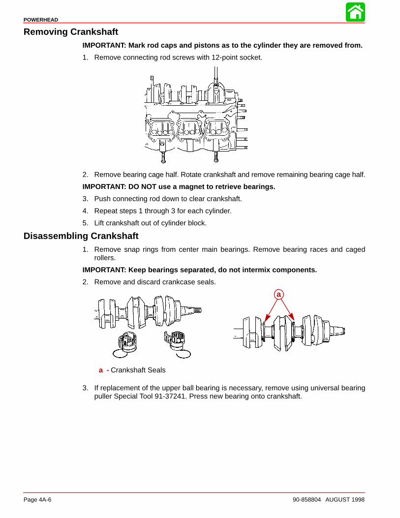
Disassembling Crankshaft1. Remove snap rings from center main bearings. Remove bearing races and caged
rollers.
IMPORTANT: Keep bearings separated, do not intermix components.
2. Remove and discard crankcase seals.
a
a - Crankshaft Seals
3. If replacement of the upper ball bearing is necessary, remove using universal bearingpuller Special Tool 91-37241. Press new bearing onto crankshaft.
POWERHEAD
90-858804 AUGUST 1998 Page 4A-7
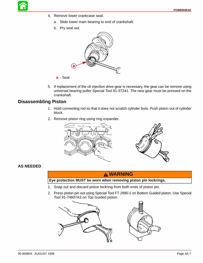
4. Remove lower crankcase seal.
a. Slide lower main bearing to end of crankshaft.
b. Pry seal out.
a
a - Seal
5. If replacement of the oil injection drive gear is necessary, the gear can be remove usinguniversal bearing puller Special Tool 91-37241. The new gear must be pressed on thecrankshaft.
Disassembling Piston1. Hold connecting rod so that it does not scratch cylinder bore. Push piston out of cylinder
block.
2. Remove piston ring using ring expander.
AS NEEDED
WARNINGEye protection MUST be worn when removing piston pin lockrings.
1. Snap out and discard piston lockring from both ends of piston pin.
2. Press piston pin out using Special Tool FT 2990-1 on Bottom Guided piston. Use SpecialTool 91-74607A3 on Top Guided piston.

POWERHEAD
Page 4A-8 90-858804 AUGUST 1998
Disassembling Cylinder Head1. Remove thermostat housing and components.
a
b
c
d
ef
g
a - Screw (4)b - Housingc - Gasketd - Springe - Thermostatf - Retainerg - Seal
NOTE: Test the thermostat by removing the rubber grommet and placing the thermostat inhot water. The thermostat should open at the temperature stamped on it.
AS NEEDED
2. Remove thermoswitch by removing snap ring retainer and pry/pull thermoswitch fromcavity.
3. Remove bolts from cylinder head cover. Remove cover. Discard gasket. Clean all gas-ket surfaces.
Inspecting and RepairingCrankshaft
1. Inspect crankshaft to drive shaft splines for wear. Replace crankshaft if necessary.
2. Inspect upper and lower crankshaft bearings for roughness and excessive looseness.Replace as necessary.
3. Check all crankshaft bearing surfaces for rust, water marks, chatter marks, uneven wearand/or overheating.
• If necessary clean surfaces with crocus cloth as shown.
POWERHEAD
90-858804 AUGUST 1998 Page 4A-9
4. Thoroughly clean (with solvent) and dry crankshaft and crankshaft ball bearings. Re-check surfaces of crankshaft. Replace crankshaft if surfaces cannot be properlycleaned up. If crankshaft will be reused lubricate surfaces with 2 cycle oil to prevent rust.
Connecting Rods1. Check connecting rods for alignment by placing rods on a surface plate. If light can be
seen under any portion of machined surfaces, if rod has a slight wobble on plate, or ifa 0.002 in. (0.051mm) feeler gauge can be inserted between any machined surface andsurface plate, rod is bent and must be discarded.
2. Overheating: Overheating is visible as a bluish bearing surface color that is caused byinadequate lubrication or excessive RPM.
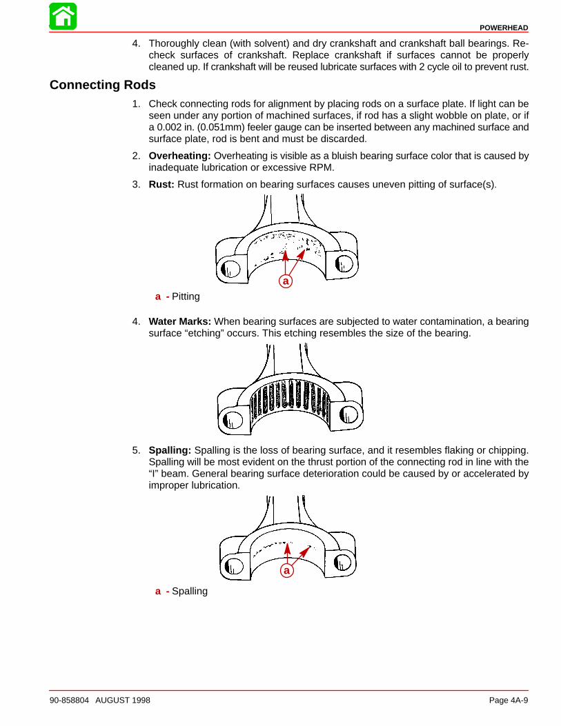
3. Rust: Rust formation on bearing surfaces causes uneven pitting of surface(s).
aa - Pitting
4. Water Marks: When bearing surfaces are subjected to water contamination, a bearingsurface “etching” occurs. This etching resembles the size of the bearing.
5. Spalling: Spalling is the loss of bearing surface, and it resembles flaking or chipping.Spalling will be most evident on the thrust portion of the connecting rod in line with the“I” beam. General bearing surface deterioration could be caused by or accelerated byimproper lubrication.
a
a - Spalling

POWERHEAD
Page 4A-10 90-858804 AUGUST 1998
6. Chatter Marks: Chatter marks are the result of a combination of low speed - low load- cold water temperature operation, aggravated by inadequate lubrication and/or im-proper fuel. Under these conditions, the crankshaft journal is hammered by the connect-ing rod. As ignition occurs in the cylinder, the piston pushes the connecting rod with tre-mendous force, and this force is transferred to the connecting rod journal. Since thereis little or no load on the crankshaft, it bounces away from the connecting rod. The crank-shaft then remains immobile for a split second until the piston travel causes the connect-ing rod to catch up to the waiting crankshaft journal, then hammers it. The repetition ofthis action causes a rough bearing surface(s) which resembles a tiny washboard. Insome instances, the connecting rod crank pin bore becomes highly polished. During op-eration, the engine will emit a “whirr” and/or “chirp” sound when it is accelerated rapidlyfrom idle speed to approximately 1500 RPM, then quickly returned to idle. If the preced-ing conditions are found, replace both the crankshaft and connecting rod(s).
a
a - Chatter Marks Between Arrows
7. Uneven Wear: Uneven wear could be caused by a bent connecting rod.
aa - Uneven Wear
CAUTIONCrocus cloth MUST BE USED to clean bearing surface at CRANKSHAFT END OFCONNECTING ROD.
320 grit Carborundum cloth MUST BE USED to clean bearing surface at PISTON PINEND OF CONNECTING ROD.
VERIFY CAP TO ROD ALIGNMENT BEFORE TORQUING ROD BOLTS.
DO NOT continue to clean connecting rod bearing surfaces after marks have beenremoved.

POWERHEAD
90-858804 AUGUST 1998 Page 4A-11
8. Clean connecting rods as necessary.
a
b
c
d
a - Attached to Drill Motorb - Crocus Clothc - Torque to 16 lb. ft. (21.7 N·m)d - Use 320 Carborundum Cloth
Top Guided(centered in bore by piston)
51536a
bc
a - Flat Washerb - Scallopedc - Smooth

POWERHEAD
Page 4A-12 90-858804 AUGUST 1998
Cylinder Block and Crankcase Cover1. Inspect cylinder head gasket surface for erosion across gasket surface. Excessive ero-
sion requires cylinder head replacement.
2. Inspect cylinder head for warpage.
(3 Cylinder Shown)
• A cylinder head with 0.012 in. (0.305 mm) or less can be resurfaced.
• If warped more than 0.012 in. (0.305 mm) replace cylinder head.
3. Measure cylinder bore diameter at top, middle and bottom of each cylinder as shown.Check for tapered, out-of-round and oversized bore.
• Refer to Specifications for Finished Hone Bore Size for Bottom Guided pistons and TopGuided pistons.
4. Measure piston ring end gap.
NOTE: Refer to Specifications for dimensions. If gap is too small widened with a file. If gapis too wide recheck bore measurements.

POWERHEAD
90-858804 AUGUST 1998 Page 4A-13
Powerhead Reassembly
Assembling PistonPlace clean needle bearings on a clean sheet of paper and lubricate with Quicksilver NeedleBearing Lubricant (92-42649A1).
NOTE: There are 29 needle bearings per piston.
CAUTIONNever intermix new needle bearings with used needle bearings at the same con-necting rod end. Never intermix needle bearings on one connecting rod with thoseof another connecting rod. Should one (or more) piston pin needle bearing of a con-necting rod require replacement (or should one or more be lost), replace all of thatconnecting rod’s piston pin needle bearings.
1. Place sleeve, which is part of Piston Pin Tool (91-74607A3), into connecting rod andinstall needle bearing around sleeve, as shown.
19537
a b
a - Needle Bearings (29)b - Sleeve [From Piston Pin Tool (91-74607A3)]
2. Place flat washers on connecting rod; keeping washers in place, carefully place pistonover end of rod. Use disassembly marks for matching rod to piston and direction of inser-tion (which side of rod is “UP”).
510831
1
b
a
a - Scribed Identification Numberb - Locating Washer
POWERHEAD
Page 4A-14 90-858804 AUGUST 1998
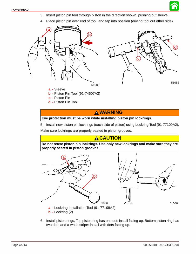
3. Insert piston pin tool through piston in the direction shown, pushing out sleeve.
4. Place piston pin over end of tool, and tap into position (driving tool out other side).
5108051086
c
d
ab
a - Sleeveb - Piston Pin Tool (91-74607A3)c - Piston Pind - Piston Pin Tool
WARNINGEye protection must be worn while installing piston pin lockrings.
5. Install new piston pin lockrings (each side of piston) using Lockring Tool (91-77109A2).
Make sure lockrings are properly seated in piston grooves.
CAUTIONDo not reuse piston pin lockrings. Use only new lockrings and make sure they areproperly seated in piston grooves.
51086 51086
a
b
a - Lockring Installation Tool (91-77109A2)b - Lockring (2)
6. Install piston rings. Top piston ring has one dot: install facing up. Bottom piston ring hastwo dots and a white stripe: install with dots facing up.
POWERHEAD
90-858804 AUGUST 1998 Page 4A-15
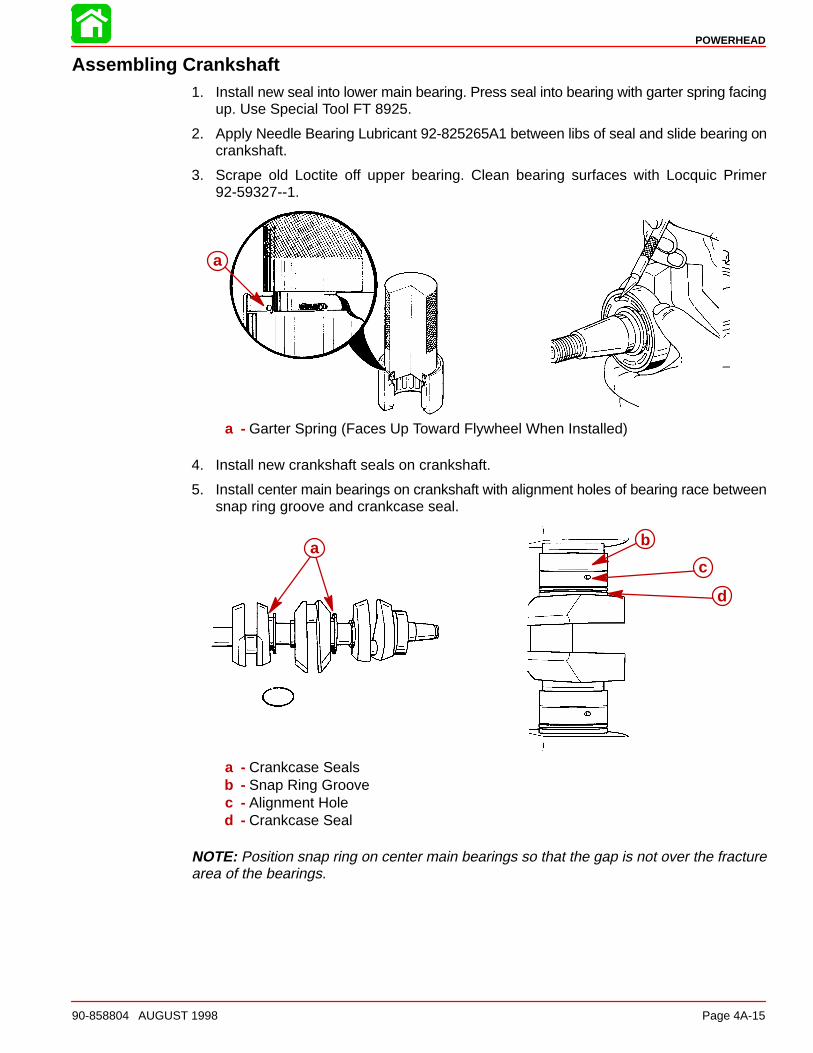
Assembling Crankshaft1. Install new seal into lower main bearing. Press seal into bearing with garter spring facing
up. Use Special Tool FT 8925.
2. Apply Needle Bearing Lubricant 92-825265A1 between libs of seal and slide bearing oncrankshaft.
3. Scrape old Loctite off upper bearing. Clean bearing surfaces with Locquic Primer92-59327--1.
a
a - Garter Spring (Faces Up Toward Flywheel When Installed)
4. Install new crankshaft seals on crankshaft.
5. Install center main bearings on crankshaft with alignment holes of bearing race betweensnap ring groove and crankcase seal.
a b
c
d
a - Crankcase Sealsb - Snap Ring Groovec - Alignment Holed - Crankcase Seal
NOTE: Position snap ring on center main bearings so that the gap is not over the fracturearea of the bearings.

POWERHEAD
Page 4A-16 90-858804 AUGUST 1998
6. Install lower bearing on crankshaft with seal.
a
b
a - Lower Bearingb - Seal
Installing Pistons Into Cylinder Block1. Coat pistons, rings, and cylinder bores with 2-cycle oil.
2. Install piston in ring compressor, Special Tool FT 2996.
IMPORTANT: Be sure to position end gap of rings at the ring alignment pin.
NOTE: Pins are 180° apart on piston.
3. Install piston in cylinder bore. Position piston so that piston dome faces intake port ofcylinder block.
a c
b
a - Alignment Pinb - Intake Portsc - Piston Dome

POWERHEAD
90-858804 AUGUST 1998 Page 4A-17
4. Push piston into cylinder bore.
NOTE: Be sure piston is installed in the same bore it was removed from.
5. Install cylinder head to prevent pistons from falling out. Do Not torque the cylinder headbolts at this time.
6. Clean cylinder block upper bearing bore with Locquic Primer 92-59327--1.
7. Apply Loctite to upper main bearing bore.
8. Install crankshaft in cylinder block.
• Align holes in center main bearings with location pins in cylinder block.
b b
aa
a - Center Main Bearing Holeb - Locating Pin
IMPORTANT: Install crankshaft with sealing ring gaps facing up. When the crankshaftis seated the ends of the sealing rings must be able to touch.
IMPORTANT: Make sure crankshaft is fully seated by pushing ends of crankshaft:there should be no rocking.
9. Spin crankshaft seals so that openings face down.
IMPORTANT: Seal rings break easily; handle carefully when turning.
IMPORTANT: Make sure upper crankshaft bearing is fully seated against the flangein the cylinder block. Tap on end of crankshaft to ensure seating.
10. Install one half of bearing cage in connecting rod.
11. Carefully align connecting rod with crankshaft.
a
a - Bearing Seated Against Cylinder Block Flange
POWERHEAD
Page 4A-18 90-858804 AUGUST 1998
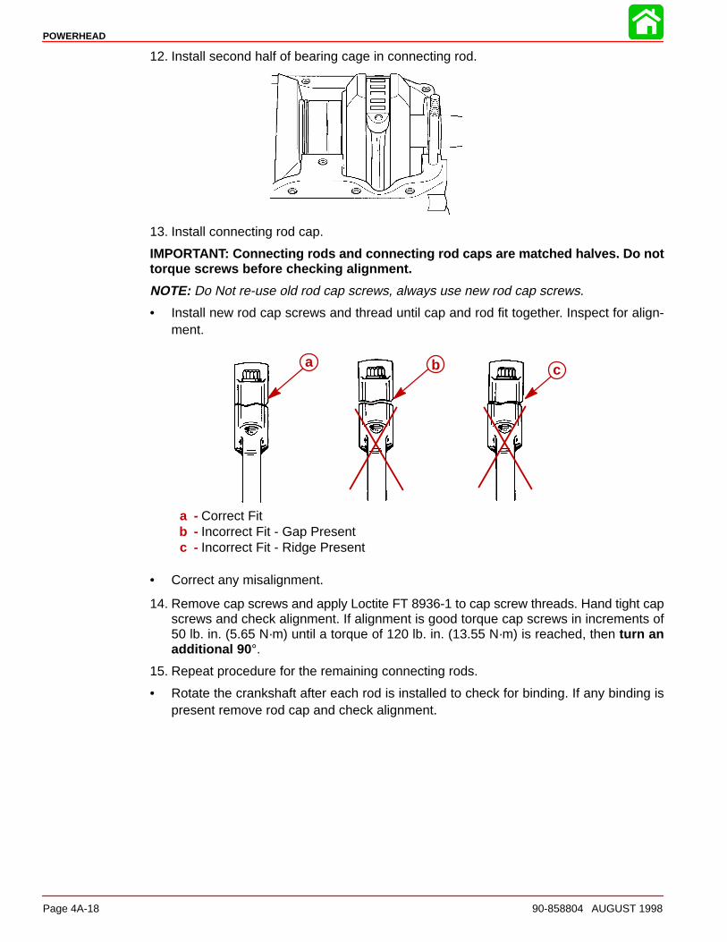
12. Install second half of bearing cage in connecting rod.
13. Install connecting rod cap.
IMPORTANT: Connecting rods and connecting rod caps are matched halves. Do nottorque screws before checking alignment.
NOTE: Do Not re-use old rod cap screws, always use new rod cap screws.
• Install new rod cap screws and thread until cap and rod fit together. Inspect for align-ment.
a b c
a - Correct Fitb - Incorrect Fit - Gap Presentc - Incorrect Fit - Ridge Present
• Correct any misalignment.
14. Remove cap screws and apply Loctite FT 8936-1 to cap screw threads. Hand tight capscrews and check alignment. If alignment is good torque cap screws in increments of50 lb. in. (5.65 N·m) until a torque of 120 lb. in. (13.55 N·m) is reached, then turn anadditional 90 °.
15. Repeat procedure for the remaining connecting rods.
• Rotate the crankshaft after each rod is installed to check for binding. If any binding ispresent remove rod cap and check alignment.

POWERHEAD
90-858804 AUGUST 1998 Page 4A-19
16. Apply Loctite 92-823089--1 to the exposed portion of the upper bearing.
17. Apply Sealer 92-90113--2 on seal surface and around main bolt holes on block.
18. Install crankcase cover on cylinder block, aligning corner dowel pins.
a
b
b
a - Sealer (92-90113--2)b - Dowel Pins

POWERHEAD
Page 4A-20 90-858804 AUGUST 1998
19. Install crankcase bolts. Following torque pattern torque bolts to 270 lb. in. (30.5 N·m).
• Check crankshaft for free rotation.
10
6
2
3
78
4
1
5
9
20. Using new gasket, install adapter plate on bottom of cylinder block. Torque bolts to 30lb. ft. (40.7 N·m).
Assembling Cylinder Head1. Install cylinder head cover on cylinder head. Torque center attaching screws to 70 lb.
in. (7.91 N·m).
2. Apply sealant 92-90113--2 to cylinder head cover on cylinder block side of cover.
3. Using new gasket, install cylinder head.
4. Torque bolts as shown to 75 lb. in. (8.5 N·m), then torque 50 lb. in. (5.6 N·m) at a timeuntil bolts are torqued to 225 lb. in. (29.14 N·m).
For S/N numbers 0E125509 and above apply light oil to threads and bolt head. Torque insequence to 120 lb. in. (13.5 N·m). Then turn an additional 90�.
18
14
10
6
2
3
7
11
1516
12
8
4
1
5
9
13
17
POWERHEAD
90-858804 AUGUST 1998 Page 4A-21
Completing Assembly
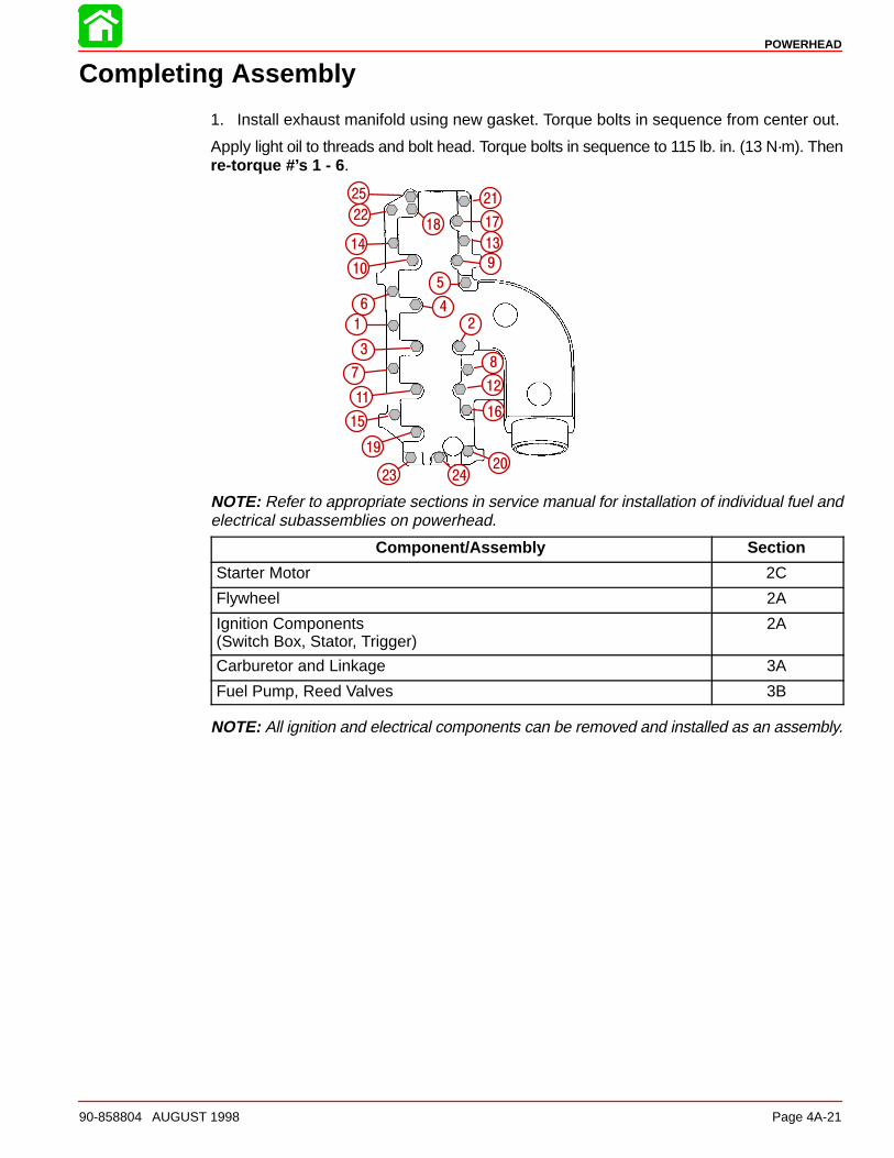
1. Install exhaust manifold using new gasket. Torque bolts in sequence from center out.
Apply light oil to threads and bolt head. Torque bolts in sequence to 115 lb. in. (13 N·m). Thenre-torque #’s 1 - 6 .
1 2
3
6 4
10
14
22
25 21
17
13
9
5
8
12
16
202423
19
15
11
7
18
NOTE: Refer to appropriate sections in service manual for installation of individual fuel andelectrical subassemblies on powerhead.
Component/Assembly Section
Starter Motor 2C
Flywheel 2A
Ignition Components(Switch Box, Stator, Trigger)
2A
Carburetor and Linkage 3A
Fuel Pump, Reed Valves 3B
NOTE: All ignition and electrical components can be removed and installed as an assembly.

POWERHEAD
Page 4A-22 90-858804 AUGUST 1998
Installing Powerhead
1. Install top exhaust boot and clamp. Install O-ring in counterbore of drive housing cover.
a
bc
d
a - Exhaust Bootb - O-Ringc - Drive Housing Coverd - Large O-Ring
2. Lubricant driveshaft splines with 2-4-C w/Teflon Lubricant 92-825407A12.
NOTE: DO NOT apply lubricant to TOP of drive shaft as grease may pre-load drive shaft/crankshaft resulting in damage to powerhead and/or pump housing.
3. Lower powerhead on drive housing cover. Align exhaust boot with exhaust elbow, drive-shaft splines, and mounting studs.
4. Torque exhaust bellows clamp screws to 50 lb. in. (5.6 N·m).
5. Connect water inlet hose to fitting on drive housing cover. Snug nut with wrench, thentighten one additional flat (60 degrees).
a
a - Water Inlet Hose

POWERHEAD
90-858804 AUGUST 1998 Page 4A-23
6. Secure powerhead to drive housing cover with nuts.
7. Torque nuts in sequence shown below. The forward and aft nuts (7, 8 and 5, 6) aretorqued to 35 lb. ft. (47.5 N·m). The left and right nuts (1, 2 and 3, 4) are torqued to 20lb. ft. (27.1 N·m).
1
24
35
6
7
8
REFER TO SECTION 6 “ENGINE INSTALLATION” TO COMPLETE INSTALLATION OFWIRE HARNESS, CONTROL CABLES, SET-UP AND TIMING.
IMPORTANT: Follow Break-In procedure as out lined in Section 6: Engine Installation.
CAUTIONSEVERE DAMAGE to your engine can result by not complying with the properbreak-in procedure.

POWERHEAD
Page 4A-24 90-858804 AUGUST 1998
Powerhead Components 120 HP
U
U
U
1 23
4
56
7
8
9
10
1112
13
14
15
1617
18
19
20
21
22
2324
25
26
27
28
29
30
31
32
33
34 35
28
28
6
9
6
Quicksilver Lubrication/Sealant Application Points
U RTV Sealant 92-90113--2

POWERHEAD
90-858804 AUGUST 1998 Page 4A-25
Item Qty. Description Torque
Lb. In. Lb. Ft. N·m
1 1 Cylinder Block
2 1 Bolt (3/8-16x3-1/8) 270 22.5 30.5
3 1 Bolt (3/8-16x2-3/4) 270 22.5 30.5
4 2 Bolt (3/8-16x3) 270 22.5 30.5
5 4 Bolt (3/8-16x2) 270 22.5 30.5
6 10 Washer
7 2 Bolt (3/8-16x1-3/4) 22.5 30.5
8 2 Bolt (1/4-20x1-1/4) 70 7.9
9 2 Dowel Pin (3/8x5/8)
10 3 Tube
11 1 Tube
12 1 Pin
13 3 Pin
14 1 Gasket Set
15 1 Gasket
16 1 Bolt (5/16-18x3/4) 13 17.6
17 1 Lock Washer (5/16)
18 1 Gasket
19 1 Cylinder Head
20 1 Cover
21 4 Bolt (1/4-20x5/8) 70 7.9
22 18 Bolt (5/16-18x2-3/8) S/N 0E125509 and Above -Apply Light Oil to Bolt Head & Threads
120 lb. in. (13.5 N·m) ThenTurn An Additional 90�
23 18 Washer - Only Used On 1995-1/2 S/N 0E125508 and Below
24 3 Cover Kit
25 1 Plug
26 12 Bolt (1/4-20x5/8) 70 7.9
27 3 Gasket
28 24 Bolt (1/4-20x7/8) 70 7.9
29 1 Cover
30 4 Bolt (1/4-20x3/4) 70 7.9
31 1 Gasket
32 1 Spring (RED)
33 1 Thermostat (130°)34 1 Spacer
35 1 Seal

POWERHEAD
Page 4A-26 90-858804 AUGUST 1998
Powerhead Components (Continued) Exhaust Manifold 120 HP
Not Used on 1996 Models
1
5
6
7
8
9
3
4
2
10
11
10
Item Qty Description Torque
Lb. In. Lb. Ft. N·m
1 1 Manifold
2 1 Gasket
3 1 Strainer Tube
4 4 Plug (3/4-14)
5 25 Washer Only Used On 1995-1/2 S/N 0E125508 and Below
6* 21 Bolt (1/4-20x3) Apply Light Oil to Bolt Head & Threads 115 13
7 4 Bolt (1/4-20x4) 115 13
8 1 Retainer
9 2 Clip
10 2 Clamp
11 1 Bellows
* Refer to torque sequence listed on page 4A-21.