SECTION 4
47
SECTION 4 PROGRAM INPUT 4.1 INTRODUCTION This section describes the procedures and options available to input data, execute the model, and obtain results. The discussion includes general input information, some definitions and rules, the program structure, and detailed explanations of the options reached from the Main Menu. Guidance is given throughout the section for selecting the most appropriate values in certain situations, but the main purpose of this section is to describe the mechanics of using the user interface. Detailed guidance on the definitions of input parameters and selection of their values is presented in Section 3. Version 3 of the HELP program is started by typing "HELP3" from the DOS prompt in the directory where the program resides. The program starts by displaying a title screen, a preface, a disclaimer and then the main menu. The user moves from the title screen to the main menu by striking any key such as the space bar. Upon reaching the main menu, the user can select any of seven options. The program automatically solicits input from the user based on the option selected. In general the HELP model requires the following data, some of which may be selected from the default values. 1. Units 2. Location 3. Weather data file names 4. Evapotranspiration information 5. Precipitation data 6. Temperature data 7. Solar radiation data 8. Soil and design data file name 9. General landfill and site information
-
Upload
navya-navvi -
Category
Documents
-
view
214 -
download
2
description
it is a good book
Transcript of SECTION 4

SECTION 4
PROGRAM INPUT
4.1 INTRODUCTION
This section describes the procedures and options available to input data, execute the model, and obtain results. The discussion includes general input information, some definitions and rules, the program structure, and detailed explanations of the options reached from the Main Menu. Guidance is given throughout the section for selecting the most appropriate values in certain situations, but the main purpose of this section is to describe the mechanics of using the user interface. Detailed guidance on the definitions of input parameters and selection of their values is presented in Section 3.
Version 3 of the HELP program is started by typing "HELP3" from the DOS prompt in the directory where the program resides. The program starts by displaying a title screen, a preface, a disclaimer and then the main menu. The user moves from the title screen to the main menu by striking any key such as the space bar. Upon reaching the main menu, the user can select any of seven options. The program automatically solicits input from the user based on the option selected. In general the HELP model requires the following data, some of which may be selected from the default values.
1. Units
2. Location
3. Weather data file names
4. Evapotranspiration information
5. Precipitation data
6. Temperature data
7. Solar radiation data
8. Soil and design data file name
9. General landfill and site information
10. Landfill profile data
11. SCS runoff curve number information
4.2 DEFINITIONS AND RULES
There are a few fundamental rules regarding the input facility that a user must keep in mind when using the model. These rules should be followed to move around the screens and to move within the same screen. Below are some definitions and rules.
1. Screens. A screen in the HELP user interface as used in this report is a single screen of information. These screens are divided into three categories:
Input Screen: a screen on which the user can input data Selection Screen: a screen from which the user selects an entry from a list

On-line Help Screen: a screen where assistance is provided. General assistance on the interface is displayed by pressing the F1 key, technical assistance by pressing the F2 key, and key operations by pressing the F3 key.
This terminology is used throughout this section. Each module consists of two types of screens: "primary" and "secondary." Primary screens are main screens that form a loop for each option of HELP. Secondary screens are displayed from the primary screens as part of the input process. These screens can be input screens or selection screens.
2. Input Cells. When the program highlights a number of spaces (called an "input cell" throughout this section), an input from the user is expected. At any input cell, the user has one of several options: enter the data requested, accept existing value, seek on-line help, or select one of the menu items listed at the bottom of the screen. Each cell is associated with a variable that is used directly or indirectly in the HELP model. Therefore, every effort must be made to assign a value to each cell when applicable. The user may input the value the first time around, or return to the cell at a later time during the program session. If an input cell is left blank, a value of zero will be assigned to the corresponding variable. If zero is not an appropriate answer to the question, it will produce erroneous results. The program will warn the user when a blank or zero is an inappropriate value.
Trailing decimal points are not required on input because the program automatically knows whether to treat a value as an integer or a floating point variable. For example, if a user wishes to enter the number nine, either 9.9 or 9.00 is acceptable, provided the input cell is wide enough.
3. Selection Cells. These are cells that are used to select from a list of options. Selection cells highlight one item at a time. An item/option must be highlighted before it can be selected. Selection is made by pressing the Enter key.
4. Moving Between Cells. The user can move from one input screen to another, by pressing the Page Down key for the next screen or Page Up key for the previous screen in the loop of primary or secondary screens. Input screens are arranged in a loop format such that if the Page Down key is pressed from the last input screen the control will return to the first screen, and vice versa. The up and down arrows are used to move up and down through the cells of a screen. If the up arrow is pressed from the first cell on the screen, control will transfer to the last cell on the same screen, and vice versa. The Tab and Shift-Tab keys can be used to move to the right and to the left, respectively, among input and selection cells that are located on the same line. In addition, the left and right arrows may be used to move between
5. Moving Within an Input Cell. Each input cell is set to a given width depending on the type of information expected to be entered in that cell. The cursor will be initially located on the first character space of the cell. The left and right arrow keys may be used to move the cursor to different spaces within the cell. If a value is typed in the first space of the cell, the cell contents will be deleted. To delete a character, move the cursor to the character location and then press the Delete key, or move the cursor to the space that is to the right of the character and then press the Backspace key. A character can be inserted between characters in an input cell by moving the cursor to the desired position and then pressing the Insert key. The Insert key will shift all characters that are at and to the right of the cursor one position to the right.

6. Terminating. At any time during the session, the user may press the F9 key to quit without saving changes, return to the main menu or exit the program. The Esc key and the Ctrl-Break keys will end some options and allow you to continue with other operations. The F10 key is used to save the data or proceed. If necessary, the user can terminate input or execution by rebooting (Ctrl-Alt-Delkeys), resetting, or turning off the computer; however, the user is discouraged from terminating a run in these manners because some of the data may be lost.
7. On-Line Help. On-line help is available to the user from any cell location on the screen. By pressing F1, information about the operations and purpose of the screen is displayed, and by pressing F2, specific technical assistance for the highlighted cell is displayed. Note that the on-line help screens contain sections from this User's Guide and that the figures and tables mentioned on the screens are located in this document. The F3 key displays various functions of keystrokes. Other specific information of the input screen is listed in menu line(s) at the bottom of screen.
8. System of Units. Throughout the HELP program the user is required to select a system of units. The HELP model allows the user to use either the customary system of units (a mixture of U.S. Customary and metric units traditionally used in landfill design and in Version 2 of the HELP model) or the Metric (SI) system of units. The user is not restricted to the same system for all data types; for example, the soil and design data can be in one system of units and the weather data can be in the other system. Moreover, it is not necessary for all types of weather data to have the same system of units (i.e., evapotranspiration data can be in the Metric system of units, while precipitation data is in customary units; the solar radiation data can be in customary units, while temperature data is in Metric units, and so on). Appropriate units are displayed in proper locations to keep the user aware of which units should be used for each data entry. Consistency in units is only required within each data type.
4.3 PROGRAM STRUCTURE
The flow or logic of the input facility of the HELP program may be viewed as a tree structure. The tree structure consists of nodes where new branches of the tree are started. The first node is called the trunk, root or parent node, and the terminal nodes of the tree are called leaves. All components (nodes) of the tree structure in the HELP model are screens that have different functions as defined previously, with the trunk node being the Main Menu. During an input session, the user should reach the leaf node if all the data for a given branch (module) are entered. Some of the nodes (screens) are common to more than one branch. The user must return to the node where the branch started in order to go to another branch. These movements can be accomplished with the special keys discussed above, such as Page Up, Page Down, F9, F10, etc.
4.4 MAIN MENU
At the beginning of each run, the Main Menu is displayed. A schematic of the main menu in Figure 3 shows the seven available modules (branches). Selection from the main menu is made by either moving the cursor to the desired module or by pressing the number of that option. Once a selection is made, program control transfers into an environment specific to that option and cannot transfer to another main menu option without exiting that

environment to the main menu and then selecting another option. A brief description of each main menu option is presented below. More details are given in the following sections about specific data requirements for each option.
Option 1 on the main menu is "Enter/Edit Weather Data." This module permits the user to read evapotranspiration, precipitation, temperature, and solar radiation data files and then review, edit, and save the data or create new files. There are four primary screens in this module; they are a file selection screen, evapotranspiration data screen, a screen that controls the method used for specifying precipitation, temperature and solar radiation data, and a screen for saving weather data files. Several options are available for specifying precipitation, temperature and solar radiations data. These vary from using default data (for precipitation only) to synthetic and other user-defined data sources, such as NOAA Tape, Climate data™, ASCII data, HELP Version 2 data, and Canadian Climatological data. Data may also be entered manually. Default and synthetic weather data generation is performed by selecting the city of interest from a list of cities and specifying (optional) additional data.
Option 2 on the main menu is "Enter/Edit Soil and Design Data." This module allows the user to read an already existing soil and design data file and then review, edit, and save the data or create a new data file. There are eight primary screens in the soil and design data module; they are a file selection screen, a landfill general information screen, three screens for entering design, soil and geomembrane liner data by layers, a screen for entering a runoff curve number, a data verification screen, and a screen for saving the soil and design data file. Input screens associated with this module provide cells for entering project title; system of units; initial soil conditions; landfill area; layer design information, such as layer type, thickness, soil texture, drainage characteristics; geomembrane liner information; and runoff curve number information including the ability to adjust the curve number a function of surface slope and length. At the end of this module, the user may request that the data be checked for possible violation of the design rules explained in Section 3. Under this module, the HELP model verifies the design data, soil and geomembrane liner properties and layer arrangement.
Option 3 on the main menu is "Execute Simulation." In this option the user defines the data files to be used in running the simulation component of the HELP model and selects the output frequency and simulation duration desired from execution. In this option the user can also view the list of files available and can make file selections from these lists.
Option 4 on the main menu is "View Results." This option allows the user to browse through the output file and examine the results of the run after executing the program. Option 5 is "Print Results," and Option 6 is "Display Guidance" on general landfill design procedures and on the HELP model itself, containing much of the text of this user's guide. Finally, Option 7 is used to "Quit" running the model and return to DOS.
In the following sections, detailed explanations of the main menu options are presented, and methods of data entry to the program and various options are discussed.

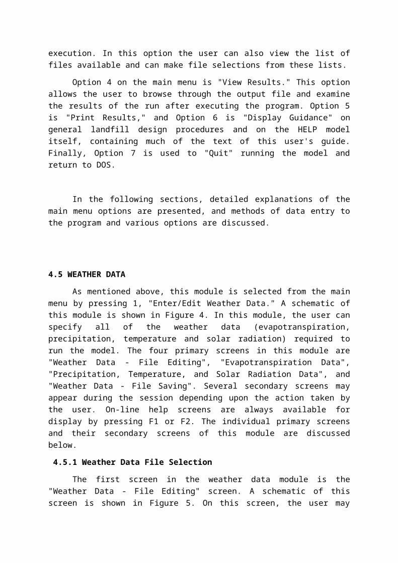
4.5 WEATHER DATA
As mentioned above, this module is selected from the main menu by pressing 1, "Enter/Edit Weather Data." A schematic of this module is shown in Figure 4. In this module, the user can specify all of the weather data (evapotranspiration, precipitation, temperature and solar radiation) required to run the model. The four primary screens in this module are "Weather Data - File Editing", "Evapotranspiration Data", "Precipitation, Temperature, and Solar Radiation Data", and "Weather Data - File Saving". Several secondary screens may appear during the session depending upon the action taken by the user. On-line help screens are always available for display by pressing F1 or F2. The individual primary screens and their secondary screens of this module are discussed below.
4.5.1 Weather Data File Selection
The first screen in the weather data module is the "Weather Data - File Editing" screen. A schematic of this screen is shown in Figure 5. On this screen, the user may enter file names of existing files to select previously generated HELP Version 3 files for editing or leave the file names blank to create new data. One file name for each of the four types of weather data to be edited is needed. The DOS path may be specified if different from the active or default drive and subdirectory, such as C:\HELP3\DATA. The following gives file naming and extension information as displayed on the screen.
Figure 5. Schematic of "Weather Data - File Editing" Screen
Data Type DOS Path (Drive and/or Subdirectory)
Precipitation Temperature Solar radiation Evapotranspiration
* Any valid DOS name that the user desires (up to eight characters) is acceptable.
The HELP program supplies the extension.
This convention must be always remembered when selecting file names for editing, saving, or converting data from other sources. However, when typing a file name on this screen, the user should not enter the extension because the program automatically assigns the proper extension to the file according to the weather types.
The current directory is displayed on the screen. The user may obtain a listing of all data files that reside on the current directory by pressing F4. By pressing F4, the program obtains a directory of all files that pertain to the weather data cell from which F4 was pressed. For example, if F4 was pressed from the temperature file cell, the program will display the list of files with an extension of D7 that reside on the currently specified directory. Up to 120 data files for any weather data type can be displayed on the screen. The name of the current

directory where these files are located is also displayed. To obtain the data files pertaining to the weather information needed that reside in another directory, the user should type in the name of a valid drive and subdirectory in the Directory column and then press F4 for the list of files in that subdirectory. To display a directory for another type of data, move the cursor to the row for that data type and repeat the process listed above.
To select a file from the list of displayed files, move the cursor to the desired file name and press Enter. This action transfers control back to the previous screen, and the name of the file just selected will be displayed in the proper cell. The user can exit the "Data Files" screen without selecting a file by pressing the Esc key.
If the user wants to enter the file name in the file cell, the user must first enter the correct directory name. If an invalid directory is entered, the program will displayed the message, "Invalid Directory," and replace the entered directory name with the default directory name (where the program was started). The user then has another opportunity to enter the correct directory name. If the program cannot find the file name as entered, the message, "File Not Found," will be displayed. The previously entered file name is erased and the user has another opportunity to enter a correct file name. Pressing Page Down causes the program to read the valid data files selected and then proceeds to the first weather data entry screen.
4.5.2 Evapotranspiration (ET) Data
The evapotranspiration data requirements are listed in Section 3 and are entered to the program from the "Evapotranspiration Data" screen. This screen contains all information required by the HELP model to construct the evapotranspiration data file (*.D11). If the user specified an edit file name for the evapotranspiration data, the contents of the file will be displayed in the appropriate cells on this screen. The user can move the cursor to any cell to edit its contents. However, if no file was selected as an edit file, then data must be specified by the user. First, the user must select the system of units to be used for the evapotranspiration data, which may be entered in customary or metric units as explained in a previous section. A schematic of this screen is shown in Figure 6. The two methods for entering this data are the manual option and the default option.
Manual Option
This option requires the user to enter all evapotranspiration data manually. The user should first specify a location in the form of a city, state and latitude, followed by the evaporative zone depth, the maximum leaf area index, the Julian dates of the start (planting) and end (harvest) of the growing season, the annual average wind speed, and quarterly average relative humidity’s (in percentages) for the entered location.
Default Option
Figure 6. Schematic of "Evapotranspiration Data" Screen
This option takes advantage of an available list of cities for which default values are provided for most of the evapotranspiration data; guidance information is available for the rest of the data. This option is triggered from any input cell on the "Evapotranspiration Data" screen by pressing F5 and selecting a location (state and city) from a displayed list of locations. This list of cities is the same as that in Table 3.
Once a city is selected, the program automatically displays values in the appropriate input cells for the city, state, latitude, growing season dates, wind speed, and the four quarterly humidity values for that location. The program, however, displays guidance information on the evaporative zone depth for that location depending on the vegetative cover. The user must enter a value of the evaporative zone depth that is appropriate for the landfill design, location, top soil, and vegetation. (See Section 3 for detailed guidance.)
The user must also enter a value for the maximum leaf area index for the site. If the value entered is greater than the default maximum allowable value based on the climate for the selected city, the program will display that value only as a guidance to the user. The user is not forced to change the entered value.
If the user decides to edit the name of the city or state, the program will erase the guidance information. Guidance is provided only for cities that are selected from the list obtained by pressing F5.
The location of the landfill being evaluated is likely to be some distance from all of the listed cities. In this case, the user has the option to select a city that has an similar climate and edit the values to improve the data or to simply enter the information manually.
The bottom line of the "Evapotranspiration Data" screen provides additional help information. Once all data are entered, the user can move on to another screen by pressing Page Up or Page Down, return to the main menu by pressing F9, or proceed to save the evapotranspiration data by pressing F10.
4.5.3 Precipitation, Temperature and Solar Radiation Data
The second screen in the weather data module is entitled "Precipitation, Temperature and Solar Radiation." From this screen, the user can select methods for creating the precipitation data file (*.D4), the temperature data file (*.D7), and the solar radiation data file (*.D13). A schematic of the main options available on this screen are shown in Figure 7. In Version 3 of the HELP model, all of the weather data need not be generated by the same method. For example, the user can enter the precipitation data using the synthetic weather generator, the temperature data using data from a NOAA data file, and solar radiation from an ASCII file. Seven options are available for entering temperature and solar radiation data. Under the precipitation data there are the same seven plus a default option. Figures 8, 9, and 10 show the possible options.
Default Precipitation
If the default precipitation option (Customary Units Only) is selected, the program will prompt the user with the list of states having default data. The HELP model provides default precipitation values for the list of cities in Table 1. To select a state, move the cursor to the desired state name and press Enter. At this time the program prompts the user with the list of cities in the selected state for which default precipitation data is available. Similarly,

the city can be selected by moving the cursor to the desired city and pressing Enter. The user can return to the "Precipitation, Temperature and Solar Radiation" screen from either list by pressing Esc. By doing so, neither a city nor a state is considered selected. However, once a city is selected, the program reads the five years of default precipitation data for the selected city. The usefulness of the default precipitation option is limited since it contains only five years of precipitation data. It is additionally limiting since these five years may be dry or wet years and may not be representative of the site in question.
The following options are available for entering "Precipitation, Temperature, and Solar Radiation" data.
Figure 7. Schematic of "Precipitation, Temperature and Solar Radiation" Screen
/ LIST OF \ ^ CITIES /
CONVERT AND IMPORT DATA
PRECIPITATION
CONVERT AND IMPORT DATA
CONVERT AND IMPORT DATA
CONVERT AND IMPORT DATA
CONVERT AND IMPORT DATA
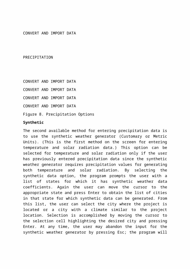
Figure 8. Precipitation Options
Synthetic
The second available method for entering precipitation data is to use the synthetic weather generator (Customary or Metric Units). (This is the first method on the screen for entering temperature and solar radiation data.) This option can be selected for temperature and solar radiation only if the user has previously entered precipitation data since the synthetic weather generator requires precipitation values for generating both temperature and solar radiation. By selecting the synthetic data option, the program prompts the user with a list of states for

which it has synthetic weather data coefficients. Again the user can move the cursor to the appropriate state and press Enter to obtain the list of cities in that state for which synthetic data can be generated. From this list, the user can select the city where the project is located or a city with a climate similar to the project location. Selection is accomplished by moving the cursor to the selection cell highlighting the desired city and pressing Enter. At any time, the user may abandon the input for the synthetic weather generator by pressing Esc; the program will return to the "Precipitation, Temperature and Solar Radiation" screen without loss of previously entered data.
Once a city is selected, the program displays another screen called "Synthetic Precipitation Data", "Synthetic Temperature Data" or "Synthetic Solar Radiation Data." On this screen, the city and state are displayed, and the user is asked to provide additional information. The first value that must be entered is the number of years of synthetic data to be generated. The rest of the information on the screen is optional. For precipitation, the user can elect to use the default normal mean monthly precipitation values provided by the HELP program or to enter normal mean monthly precipitation values to be used in generating the synthetic precipitation for that location. For temperature, the user has the option to use the default normal mean monthly temperature values provided by the HELP program or to enter normal mean monthly temperature values to be used in generating the synthetic temperature for that location. Users are encouraged to enter their own normal mean monthly values especially if the landfill is not located at the selected city. The program uses the normal mean monthly data to adjust the data generated by the synthetic weather generator. If the user decides not to use the default values, the program will transfer control to the normal mean monthly data option under the "User" heading. At this time the user must input values for January through December. A blank cell for a given month will be recorded as zero, and the user must be careful not to leave a cell without an entry. A zero entry, however, is a valid entry. For solar radiation the optional value is the latitude for the location. The default latitude of the selected city will be displayed, but the user is encouraged to enter the latitude of the actual landfill location to obtain better solar radiation values.
Create/Edit
If the user selects the create/edit option (Customary or Metric Units) for manually entering or editing precipitation, temperature and/or solar radiation data, the program prompts the user with a request to enter the city and state of the location and the units that will be used for entering the data manually. These requests appear on the same screen as "Precipitation, Temperature and Solar Radiation" screen and will be filled in with information when editing an existing data file. The user may press the Esc key to abandon the entry of this information and return to the selection of another weather data option. Once the location and units are specified, the program displays the yearly data screen.
Yearly Data Screen
This screen is like a spreadsheet that has four columns. Two of these columns are for the precipitation data, and one column each is for temperature and solar radiation. The first column is for the year for which the precipitation data is to be entered, and the second column is for total annual precipitation. The user cannot access the yearly total precipitation column since this total is computed by the program after the daily data for the year is entered. If the user reaches this screen from the precipitation option on the "Precipitation, Temperature, and
Solar Radiation" screen, the user will only be able to move within the column under precipitation. Similarly, if the user reaches this screen from the temperature data option, then only movement in the temperature column is permitted, and analogously, for the solar radiation option.
To enter a new year of daily values, the user should move the cursor to a empty cell, type in the year and press Enter. The program will display the daily data screen on which the daily values are entered. The user can return to the yearly data screen by pressing F10 to retain the data (to a temporary file) or by pressing Esc to abandon the created data.
The user can enter up to 100 years of daily data. The yearly data screen can only display 20 rows at a time. The user, however, can move the cursor to the bottom of the screen and then cursor down to move to the next row until the hundredth row is displayed. Similarly, the user can move the cursor upward to display the rows in the spreadsheet that are not shown on the screen, if any. To move down 20 rows, press Page Down, and to move up 20 rows, press Page Up. To reach the last row, press End, and to go to the first row press Home.
To edit an existing year of daily values, the user must first create and/or read weather data. If the data were previously saved, the user should specify the existing data file "Weather Data - File Editing" screen immediately after selecting the "Enter/Edit Weather Data" option from the main menu. The HELP model reads the data from the edit file and stores it in a temporary file. Upon entering the create/edit option, the program displays the list of years for precipitation, the total annual precipitation for each year, and a list of years for the temperature and solar radiation data. To edit, move the cursor to the year that is to be edited and press Enter. The program will display the daily data screen and
the user may type over any values that need to be edited. The operation of the yearly data spreadsheet and the daily data spreadsheet is the same when editing existing data or when creating new data.
After entering or editing years of daily weather data, the user can return to the "Precipitation, Temperature and Solar Radiation" screen to exercise other weather data options. To retain the newly created or edited years of daily weather data, the user should press F10 from the yearly data screen; the program will then replace the existing temporary data file containing all of the years of data for that type of weather data. To lose the newly entered or edited daily data, the user should press F9 or Esc; the program will retain the previously existing temporary data file containing the values of that type of weather data prior to entering the create/edit option.
Daily Data Screen
Upon selecting or specifying a year from the yearly data screen, the program displays the daily data screen, a spreadsheet for entering daily data. This spreadsheet consists of 10 columns and 37 rows. The spreadsheet contains information on the file name, the year, month, and day. This information is displayed at the top of the spreadsheet. The day and month are continuously updated as the user moves from one cell to another. The first day is considered January 1, and the last day is December 31. The spreadsheet is divided into two parts, the first part being rows 1 through 19, and the second part, rows 20 through 37. The user can move the cursor to the bottom of the screen and cursor down to move to the next row until the 37th row is displayed. Similarly, the user can move the cursor upward to display

any rows in the spreadsheet that are not shown. To move from the upper to the lower portions of the spreadsheet and vice versa, press Page Down and Page Up, respectively. To reach the last cell in the spreadsheet, press End, and to return to the first cell, press Home.
The user should input values one day at a time without leaving empty cells between months. For example, the first month (January) will extend to the first cell (or column) in the fourth row. The values for the first day in February should start in column 2 of row 4; no empty cells are left between months. An empty cell is considered by the program to indicate a value of zero for that day. A zero is a valid entry. The program keeps track of leap years and adjusts the month and day at the top of the spreadsheet accordingly. Since there are 37 lines with each line containing 10 days of data, there will be empty cells at the end of line 37 in the spreadsheet. These cells are ignored by the program.
If the user decides to quit entering data in the daily spreadsheet and return to the yearly spreadsheet, the user should press the Esc key. By doing so, whatever data were entered on the daily data sheet will be lost; the previously existing data will be retained. To exit the daily spreadsheet and retain the data entered on that sheet, the user should press F10. Note that the F10 key will retain the data in a temporary file only and not in any previously selected file. A separate temporary file is maintained for each year of daily data.
Once the user returns to the yearly weather sheet, more years can be entered or edited, and the daily values for these years can be input on the daily sheet in the same manner described above. After exiting the precipitation spreadsheet by pressing F10, and upon returning to the yearly sheet, the annual total precipitation for that year is computed and displayed next to the year.
Editing Data on Yearly Data Screen
Besides selecting years for creating or editing daily data, the user has the options on the yearly data screen to select only a portion of a weather file for future use, to rearrange the years of data, to repeat the same year(s) of data for a longer simulation period or to insert years of data into an existing file. These options are performed using the functions to add (insert) a year above or below an existing year in the list of years, delete a year, move a year to a position above or below an existing year in the list of years, or copy a year to a position above or below an existing year in the list of years. The options are performed only on the type of data (precipitation, temperature or solar radiation) highlighted when the create/edit option was selected. This is done by using the following key combinations of functions:
Alt A adds/inserts a year (either new, being moved or being copied) above the highlighted year (where the cursor is positioned)
Alt B adds/inserts a year (either new, being moved or being copied) below the highlighted year (where the cursor is positioned)
Alt D deletes the highlighted year (where the cursor is positioned)
Alt M tags the highlighted year (where the cursor is positioned) to be moved to another location to be designated using the cursor and Alt A or Alt B
Alt C tags the highlighted year (where the cursor is positioned) to be copied to another location to be designated using the cursor and Alt A or Alt B

To add a new year directly above a certain year, for example above the year on line 29 (Line numbering is shown on the left edge of the screen.), the user should move the cursor to line 29, hold the Alt key down, and press A. The result of this action is that a blank cell is inserted above line 29, and the program shifts the year on line 29 and all the years below it one line downward (i.e. year on line 29 moves to line 30, year on line 30 moves to line 31, etc.), and line 29 will be a blank line for the user to enter the value for the new year.
To add a year directly below a certain year, for example below the year on line 5, the user should move the cursor to line 5, hold the Alt key down, and press B. The result of this action is that a blank cell is inserted below line 5, and the program shifts the year on line 6 and all the years below it one line downward (i.e. year on line 6 moves to line 7, year on line 7 moves to line 8, etc.), and line 6 will be a blank cell for the user to enter the value of the new year.
The Alt D combination causes the program to delete a year from the list of years. For example, to delete the year on line 15, the user should move the cursor to line 15, hold the Alt key down, and press D. The program will delete information on line 15 and will shift the years on lines 16 to 100 upward one line (i.e., year on line 16 moves to line 15, year on line 17 moves to line 16, etc.), and cell on line 100 becomes an empty cell. The user is cautioned that the deleted year cannot be recovered without quitting and losing all changes (F9 or Esc). The original temporary file is replaced only when the changes are finally retained by pressing F10 from the yearly data screen.
The copy command allows the user to place a year that is identical to another year on another line. For example, to copy the year on line 70 to line 5, move the cursor to line 70 and press the Alt C combination, then move the cursor to line 5 and press the Alt A combination. At this point, the user must specify a value for the new year; the value must be different from the value of any other year in the data set for that type of weather data. This action will cause the new value for the year to appear on line 5 but the daily values will be the same as those found for the year copied and previously found in line 70. (The user may obtain the same result after the Alt C combination by moving to line 4 and pressing the combination Alt B).
The move command allows the user to move one year from one location on the yearly data screen to another. For example, to move the year on line 32 above the year on line 56, move the cursor to line 32, press the Alt Mcombination, and move the cursor to line 56 and press the Alt A combination. This action will cause the year on line 32 to be deleted and be placed directly above the year on line 56. (The user may obtain the same result after the Alt M combination by moving to line 55 and pressing the combination Alt B).
The Esc key can be used to quit the move and copy functions (after pressing Alt M or Alt C and before pressing Alt A or Alt B. By editing the data as discussed above, the user is actually arranging the order of the precipitation data of the years. Actual rearranging of data in the data file, however, takes place only after the user presses F10.
NOAA Tape Data
This option allows the user to enter data to the HELP model from a NOAA data set
(Customary Units Only). If this option is selected, the user must enter the city and state for the site and the NOAA file name. For the precipitation and temperature options, the NOAA
data file should contain daily Summary of Day data written in as-on-tape format. Note that for temperature data two file names are requested, one for the maximum temperature and the other for the minimum temperature. If the user has only a mean temperature data file, the mean temperature data file name should be entered for both maximum and minimum temperature data file names. For the solar radiation option the NOAA data file should contain hourly Surface Airways data written in as-on-tape format. Example NOAA data files are included with the HELP program -- PC49215A.PRN for precipitation, MX49215A.PRN for maximum temperature and MN49215A.PRN for minimum temperature. When entering the NOAA file name, the user should include the DOS path (if the file location is different than the default directory), file name and extension. The user can abandon the entry of this data by pressing Esc. Once valid information is entered, the program reads the data from the specified file and converts it to the HELP Version 3 format.
Climatedata™
This option allows the user to enter daily precipitation or temperature data to the HELP model from Climatedata™ (Customary Units Only). If this option is selected, the user must enter the city and state for the site and the Climatedata™ file name. Note that for temperature data, two file names are requested, one for the maximum temperature file and the other for the minimum temperature file. The Climatedata™ file should have been created by exporting or printing the CD-ROM data to an ASCII print file. This same format is used by data bases other than Climatedata™ and therefore these data bases can be converted using this same option. Example Climatedata™ files are included with the HELP program -- BIRM.PRC for precipitation, BIRM.MAX for maximum temperature and BIRM.MIN for minimum temperature. When entering the Climatedata™ file name, the user should include the DOS path (if the file location is different than the default directory), file name and extension. The user can abandon the entry of this data by pressing Esc. Once valid information is entered, the program reads the data from the specified file and converts it to the HELP Version 3 format.
ASCII Data
This option allows the user to enter daily weather data to the HELP model from ASCII data files (Customary or Metric Units). The ASCII data set is composed of lines of data whose values are separated by a blank(s), a comma or other non-numeric symbol. If this option is selected, the user must enter the city and state for the site, the units of the data in the ASCII files. The user can abandon the entry of this data by pressing Esc. Once valid information is entered, the program then asks for the file name and year of the ASCII data set, one year at a time. Each file should contain only one year of daily values for a particular type of data, either precipitation, mean temperature or solar radiation. Example ASCII data files are included with the HELP program -- RAIN.1 and RAIN.2 for precipitation, TEMP.1 and TEMP.2 for temperature and SOLAR.1 and
SOLAR.2 for solar radiation. When entering the ASCII data file name, the user should include the DOS path (if the file location is different than the default directory), file name and extension. In order to return from this option to the "Precipitation, Temperature, and Solar Radiation" screen, press Esc.

HELP 2
This option allows the user to enter weather data to the HELP model Version 3 from a data file used in the HELP model Version 2 (Customary Units Only). If this option is selected, the user must enter the city and state for the site and the HELP Version 2 data file name. Example HELP 2 data files are included with the HELP program -- ALA4 for precipitation, ALA7 for temperature and ALA13 for solar radiation. When entering the HELP 2 data file name, the user should include the DOS path (if the file location is different than the default directory), file name and extension. The user can abandon the entry of this data by pressing Esc. Once valid information is entered, the program reads the data from the specified file and converts it to the HELP Version 3 format.
Canadian
This option allows the user to enter weather data to the HELP model from a Canadian Climatological Data (Surface) file (Metric Units Only). If this option is selected, the user must enter the city and state for the site and the Canadian Climatological Data file name. The precipitation and mean temperature data files should contain daily values written in either compressed or uncompressed diskette format. The solar radiation data file should contain hourly global solar radiation values also written in either compressed or uncompressed diskette format. Example Canadian data files are included with the HELP program -- CAN4.DAT and CCAN4.DAT for precipitation, CAN7.DAT and CCAN7.DAT for temperature and CAN13.DAT and CCAN13.DAT for solar radiation. When entering the Canadian data file name, the user should include the DOS path (if the file location is different than the default directory), file name and extension. The user can abandon the entry of this data by pressing Esc. Once valid information is entered, the program reads the data from the specified file and converts it to the HELP Version 3 format.
4.5.4 Saving Weather Data
During the creation of the weather data explained above, the data are saved in temporary files. To save the data to permanent files, the user must press F10 from the primary screens. Once the F10 key is pressed, the program verifies that all the data have been entered. If any of the data is incomplete, the program displays a list of the problem areas. The user can return to the primary screens to complete the data or continue to save the incomplete data. After displaying the deficiencies, the program displays the "Weather Data - File Saving" screen. Here the user may save all or only some of the four weather types, or completely abandon the save option. The user should tag each type of data to
be saved by entering a "Y" in the "SAVE" column and those not to be saved by entering a "N" in the "SAVE" column. Default file names are displayed in appropriate locations on this screen; these are the same names as used in Version 2. At this time, the user may enter new file names for any or all of the four types of weather data. (See Section 4.5.1 for file naming convention used in HELP.) If the file already exists, the program will display "File Already Exists" after entering the name. After replacing all file names of interest, the user should press F10 or Page Down to complete the saving to the requested file names. If files already

exists for any of the file names as they would for the default names, the program will ask the user about overwriting each existing file. If the user answers "Y" for all of the files, the program will overwrite the files, complete the saving process and return to the main menu. If the user answers "N" for any file, the program will interrupt the saving, return to the "SAVE" column and change the tag to "N". The user can then change the tag back to "Y", rename the file, and restart the saving by pressing F10 or Page Down. The program provides other options listed on the "File Saving" screen to enable the user to return the weather data entry screens (Page Up) or to return to the main menu without saving the data (F9). The user must be cautioned that the F9 option will cause all the data created (if any) to be lost. Figure 11 shows the available options.
Figure 11. "Weather Data - File Saving" Screen Options
This module is selected from the main menu by pressing 2, "Enter/Edit Soil and Design." While in this module, the user will be able to enter site information, a landfill profile, layer design data, characteristics of soils, geomembranes and other materials, and SCS runoff curve number information. The primary screens in this module are the "Soil and Design Data - File Editing" screen, "Landfill General Information" screen, three Landfill Profile Design and Layer Data screens, "Runoff Curve Number Information" screen, "Verification and Saving" screen and "Soil and Design Data - File Saving" screen. Several secondary screens may appear during the session depending on the action taken by the user. On-line help screens are always available for display by pressing F1 or F2.
The individual primary screens and their secondary screens of this module are discussed below. Figure 12 shows a schematic of the soil and design data module.
Figure 12. Schematic of Soil and Design Data Module
4.6.1 Soil and Design Data File Selection
The first screen in the soil and design module is the "Soil and Design Data - File Editing" screen. A schematic of this screen is shown in Figure 13. On this screen the user may enter the file name of an existing file to select a previously generated HELP Version 3 file for editing or leave the file name blank to create new data. When selecting a file to be edited, the user may specify the DOS path if different from the default drive and subdirectory, such as C:\HELP3\DATA. The default directory is initially displayed in the directory cell on the screen. If the user specifies a drive or a directory that does not exist, the program will display respectively "Invalid Drive" or "Invalid Directory" and replaces the content with the default directory. The soil and design data file may have any valid DOS name of up to 8 characters. If the user enters an illegal file name, the program displays "Bad File Name" and clears the file name. If the user specifies a file name that does not exist, the program displays "File Not Found" and clears the file name.

The program adds an extension of .D10 to the file name. As such, the user should not specify the extension in HELP Version 3 whenever entering a file name for editing or saving.
Figure 13. "Soil and Design Data - File Editing" Screen Options
As shown in Figure 13, the user may obtain a listing of all soil and design data files that reside on the directory currently specified in the directory cell by pressing F4. Up to 120 data files can be displayed on the screen. The name of the current directory where these files are located is also displayed. To change to another directory, the user should enter the name of that directory in the column labeled DIRECTORY. To select a file from the list of displayed files, move the cursor to the file and select it by pressing Enter. This transfers control back to the previous screen and the name of the file just selected will be displayed in the proper cell. The user can exit the list-of-files screen without selecting a file by pressing F4 again or Esc.
When ready to proceed to enter new data or edit existing data, the user should press Page Down or F10. The program then reads the data file to be edited, if a file is specified, and proceeds to the "Landfill General Information" screen. If a new data set is to be created (file name left blank), the program initializes the soil and design data and then asks for the system of units to be used throughout the module (Customary or Metric). Proper units are displayed throughout the module for entries that require units.
4.6.2 Landfill General Information
The second input screen in the soil and design data module is the "Landfill General Information" screen. Figure 14 shows the screen and its branches as a schematic. By moving the cursor to the appropriate cell, the user can enter new information or edit the information that was read from the edit file. The first entry is the project title which is only used for identification of the simulation.
Figure 14. Schematic of "Landfill General Information" Screen
The second entry on this screen is the landfill area. The units of the area are displayed next to the input cell according to the system of units selected. The user should enter the area in acres for customary units or in hectares for Metric units. The third entry is for the percent of area where runoff is possible. This variable specifies the portion of the area that is sloped in a manner that would permit drainage off the surface. The runoff estimates predicted by the model are equal to the computed runoff by the curve number method times this percent. The difference between the computed runoff and the actual runoff is added to the infiltration.
Next, the user must select the method of moisture content initialization; that is whether or not the user wishes to specify the initial moisture storage. If the user answers "N" (no) to this

question, the program assumes near steady-state values and then runs the first year of the simulation to improve the initialization to steady-state. The soil water contents at the end of this year of initialization are taken as the initial values for the simulation period. The program then runs the complete simulation, starting again at the beginning of the first year of weather data. The results for the initialization period are
not reported. However, if the user answers "Y" (yes), the user is requested to enter the amount of water or snow water on the surface in the units selected. Later, the user should enter the initial moisture content of each layer as explained in the next section.
4.6.3 Landfill Layer Data
The next step in the soil and design data module is to input the design specifications of the landfill profile, one layer at a time. Layer data are entered in three screens. These screens have a spreadsheet layout where each row represents a layer. Figure 15 shows the three spreadsheets and their associated screens. The first row of cells on the screens is the uppermost layer in the landfill. Each column of cells on the screens represents a variable or a property of the layer or its material. Variable names are listed in the first two rows of the screen, and the third row contains the units of that variable, if any. Every highlighted cell is associated with a highlighted property (heading of a column) and a highlighted layer number (row label). The user should enter the value of the specified property for the corresponding layer. All entries must obey certain rules which are discussed below.
Figure 15. Schematic of Landfill Layer Data
Layer Type
The user should input layer type in the first column of the spreadsheet. The four layer types and their associated code numbers that the program recognizes are vertical percolation (1), lateral drainage (2), barrier soil liner (3), and geomembrane liner (4). These are defined as follows:
1. A layer of moderate to high permeability material that drains vertically primarily as unsaturated flow is classified as a vertical percolation layer as long as it is not underlain by a liner with a lateral drainage collection and removal system. The primary purpose of a vertical percolation layer is to provide moisture storage; as such, top soil layers and waste layers are often vertical percolation layers.
2. A layer of moderate to high permeability material that is underlain by a liner with a lateral drainage collection and removal system is classified as a lateral drainage layer. The layer drains vertically primarily as unsaturated flow and laterally as a saturated flow.
3. A layer of low permeability soil designed to limit percolation/leakage is classified as a barrier soil liner. The layer drains only vertically as a saturated flow.
4. A geomembrane (synthetic flexible membrane liner) designed to restrict vertical drainage and limit leakage is classified as a geomembrane liner. Leakage is modeled as vapor diffusion and leakage through small manufacturing defects and installation flaws.
While the HELP program is quite flexible, there are some basic rules regarding the arrangement of layers in the profile that must be followed.
1. A vertical percolation layer may not be underlying a lateral drainage layer.
2. A barrier soil liner may not be underlying another barrier soil liner.
3. A geomembrane liner may not be placed directly between two barrier soil liners.
4. A geomembrane liner may not be underlying another geomembrane liner.
5. A barrier soil liner may not be placed directly between two geomembrane liners.
6. When a barrier soil liner or a geomembrane liner is not placed directly below the lowest drainage layer, all drainage layers below the lowest liner are treated as vertical percolation layers. Thus, no lateral drainage is computed for the bottom section of the landfill.
7. The top layer may not be a barrier soil liner.
8. The top layer may not be a geomembrane liner.
9. The profile can contain no more than a total of five barrier soil liners and geomembrane liners.
The program checks for rule violations only at the time the user saves the data. Therefore, to reduce the time involved in evaluating a landfill, the user is encouraged to design a proper layer sequence before saving the data.
In the second column, which has the heading "Layer Thickness," the user should enter the thickness of each layer in the landfill profile even for the geomembrane liner, in inches or cm. The values must be greater than zero; a blank cell is taken as a value of zero. Again, during data verification the program checks for layer thickness of zero and issues a violation statement when the user tries to save the data.
In the third column, the user should enter the soil texture number of the soil that forms the layer. The 4 possible options for the user to enter soil texture numbers are:
1. Select from a list of default textures for 42 soils, wastes, geomembranes, geosynthetics and other materials.
2. Select from a library of user-defined textures that were previously saved and numbered by the user (up to 100 such textures are allowed).
3. Enter a new soil texture number that can be used again in this design and that can later be saved in the library of user defined textures (material properties must also be entered manually for this texture).
4. Leave the texture number blank and enter the material properties manually. Default Soil/Material Textures

Default soil/material textures have numbers from 1 to 42 and are listed in Table 4. The user can either type the soil texture number or press F6 to select a texture from the list of default textures. If the user enters a default soil/material texture number manually, the program automatically assigns the default values for porosity, field capacity, wilting point, and hydraulic conductivity to the layer. On the other hand, the user may press F6 to obtain the list of soil textures on a separate screen. On the soil texture screen, the user can move the cursor to the desired texture or press Page Down to display the rest of the default soil textures. After cursoring to the desired texture, press Enter to select it. At this time, program control returns to layer spreadsheet screen and displays the selected soil texture number, along with the porosity, field capacity, wilting point, and hydraulic conductivity in appropriate cells. Notice that the only information available for the
default geomembrane liners is the hydraulic conductivity (liner vapor diffusivity). If the user changes any of the four soil properties obtained for a default soil/material texture, the program automatically resets the soil texture number to 0. The user can then assign the values a new soil texture number that is not used in either the list of default or previously saved user defined textures if the user wishes to save the material characteristics for future use.
As mentioned above, default soil/material textures are obtained by pressing F6 and are available on all three screens. To move from one screen of default soil/material textures to another the user should press Page Up or Page Down. To return to the layer spreadsheet without making a selection, press Esc. A selection is made only by moving the cursor to the desired soil texture and pressing Enter.
User-Defined Soil Texture
In Version 3 of the HELP model, the user has three options to specify material characteristics, in addition to selecting soil textures from the default list. One method is to enter all of the material characteristics manually without specifying a soil texture number. This method is used when the user does not wish to save these characteristics for use again in this simulation or future simulations. The second method, which allows the user to assign a new soil texture number to the manually entered values for the soil properties, is used when the same characteristics are to be used in future simulations and the characteristics are to be permanently saved in a library of user-defined textures. A library of up to 100 soil textures may be saved in a "user-defined soil texture" data file. The creation and addition of textures to this file are explained in Section 4.6.5 of this User's Guide. The third method is to select a user-defined texture that was previously saved in the library. If this library of user-defined soil textures exists, the user can display the list of available textures for selection by pressing F7. Selecting a user-defined soil texture for a given layer is identical to that of selecting a default soil/material textures; the user should move the cursor to the desired soil texture and press Enter. At this point, program control returns to the layer spreadsheet and displays soil texture values, porosity, field capacity, wilting point, and hydraulic conductivity of the selected soil in the layer (row) where F7 was pressed. Also, in the same manner as in default soil/material textures, the user can simply type the number of the user-defined soil texture in "Soil Texture No." column of the first screen of the layer spreadsheets, and the program will automatically obtain the soil characteristics for that soil texture and place them in the proper location on the layer spreadsheet.

Whenever F7 is pressed, control transfers to the user-defined soil textures. To move among pages of soil textures press Page Up and Page Down. To make a selection, press Enter, and to return to the layer spreadsheet without making a selection, press Esc.
The values entered for the moisture storage parameters in columns 4 through 7 of the first screen of layer spreadsheets are interrelated. In column 4 the porosity must be greater than zero but less than 1. In column 5 the field capacity must be between zero and 1 but must be smaller than the porosity. In column 6 the wilting point must be greater than zero but less than the field capacity. In column 7 the initial moisture content must be greater than or equal to the wilting point and less than or equal to the porosity. If the user had indicated on the "Landfill General Information" screen that the program should specify initial moisture content for the soil layers, the program will ignore all input in column 7. As such, the user does not need to enter data in this column. On the other hand, if the user had indicated that the user wishes to specify the initial moisture content, these values must be entered manually. An empty cell is interpreted as zero for initial moisture, violating the rules. If the layer is a liner, the program during execution automatically sets the initial water content equal to the porosity of the layer. The program will detect violations of these values and will report them to the user during verifications when the data is to be saved to a file.
The second screen of layer spreadsheets can be obtained by pressing Page Down. On this sheet the user will notice that the layer type is already appearing. In the first column of cells the saturated hydraulic conductivity must be specified in the appropriate units (cm/sec). If the soil texture selected was a default soil/material texture or a user-defined soil texture, the saturated hydraulic conductivity will be displayed in this column. Remember that changing the saturated hydraulic conductivity causes the soil texture number on the previous screen to revert to zero in the same manner as changing any of the other material characteristics (porosity, field capacity or wilting point).
Drainage Layer Design
Information on lateral drainage layer design must be entered manually for each lateral drainage layer directly above the liner regardless of the method used to enter soil textures. The required information is the drainage length, drainage layer slope, and recirculation percentage and recirculation destination. These parameters are found in the second through fifth column of cells on the second spreadsheet screen of layer data. These columns are used only for the lateral drainage layers directly above the liner; data placed in rows for other layers will be ignored during execution. The second column of cells on this second screen of layer data is for entering the maximum drainage length of lateral drainage layers, which is the length of the horizontal projection of the flow path down the slope of a liner to the water/leachate collection system. This length must be greater than zero. In third column of cells the user should enter the drain slope in percent. This slope is the maximum gradient of the surface of the liner at the base of the lateral drainage layer; this is the slope along the flow path.
In Version 3, the HELP program allows leachate/drainage recirculation to be simulated. The amount of leachate/lateral drainage to be recirculated from a given layer should be entered as a percent of the layer's drainage in the fourth column of cells. The layer to which this leachate drainage should be recirculated should be entered on the same row in the fifth column of cells. The value entered is the number of the layer receiving recirculation. Layer numbers are

those numbers displayed on the left side of the screen. These numbers are 1 through 20 and refer to the order of the layers in the profile. The
HELP model does not allow leachate recirculation to a liner.
Version 3 of the HELP model also allows the user to specify subsurface inflow into the landfill from a groundwater source. The amount of subsurface inflow into each layer should be entered in the last column of the second spreadsheet of layer data and is considered to be a steady flow rate into the landfill at the layer where the inflow value is entered. If subsurface inflow is specified for the bottom layer, the program will assume no leakage through the bottom of the landfill. For most landfills, the inflows will be zero and this column can be left blank.
After entering the necessary values in the second spreadsheet screen of layer data, the user should press Page Down to go to the third and last screen of layer data. Pressing Page Up will return to the first spreadsheet of layer data, allowing the user to edit the previously entered values. Again, on the third spreadsheet screen, the layer type of all layers in the profile are displayed to aid in positioning data on the screen.
Geomembrane Liner Design
All of the entries on third screen of layer data pertain to geomembrane liner properties such as geomembrane liner pinhole density, geomembrane liner installation defect density, geomembrane liner placement quality, and associated geotextile transmissivity (if present). Values must be entered for each geomembrane liner (layer type 4) in the profile. Guidance on estimating the pinhole and installation defect density as well as definitions for these parameters is provided in Section 3. The placement quality options are also described in Section 3 and are presented below. The geotextile transmissivity should be specified only when a placement quality of 6 is used.
In the third column of cells the user should input the geomembrane liner placement quality. The HELP program recognizes the following six types of placement quality.
1. Perfect contact
2. Excellent contact
3. Good field placement
4. Poor field placement
5. Bad contact -- worst case
6. Geotextile separating geomembrane liner and controlling soil layer
Typically, placement quality 6 would not be used with a geosynthetic clay liner (GCL) despite the presence of a geotextile since, upon wetting, the clay extrudes through the geotextile and provides intimate contact with the geomembrane.

After completing input for one layer, the user can go back to the first spreadsheet and enter information for other layers. Page Up and Page Down are used to move backward and forward between spreadsheets. The user may also input values on one spreadsheet completely filling it, and move on to the next spreadsheet filling in the information for the layers entered in the first spreadsheet and so on. No blank rows be left in the spreadsheet between layers; however, if the user does leave some blank lines, the program will not save these as layers.
Layer Editing
While entering or editing the properties of the layers in the landfill defined in the three spreadsheets of layer data, the user has the option to add a layer to the profile, delete a layer, move a layer to another location in the profile, or copy a layer to another location. When using these layer editing functions, the program operates simultaneously on all three screens of layer data. This is done by using the following key combinations:
Alt A adds/inserts a layer (either new, being moved or being copied) above the highlighted layer (where the cursor is positioned)
Alt B adds/inserts a layer (either new, being moved or being copied) below the highlighted layer (where the cursor is positioned)
Alt D deletes the highlighted layer (where the cursor is positioned)
Alt M tags the highlighted layer (where the cursor is positioned) to be moved to another location to be designated using the cursor and Alt A or Alt B
Alt C tags the highlighted layer (where the cursor is positioned) to be copied to another location to be designated using the cursor and Alt A or Alt B
To add a new layer directly above a certain layer, for example above the layer on line 6 (shown on the left edge of the screen), the user should move the cursor to line 6, hold the Alt key down, and press A. The result of this action is that a blank line is inserted above the layer that was at line 6, and the program shifts the layer on line 6 and all the layers below it one line downward (i.e. layer on line 6 moves to line 7, layer on line 7 moves to line 8, etc.), and line 6 will be a blank line for the user to enter the values for the new layer.
To add a layer right below a certain layer, for example below the layer on line 5, the user should move the cursor to line 5, hold the Alt key down, and press B. The result of this action is that a blank line is inserted below line 5, and the program shifts the layer on line 6 and all the layers below it one line downward (i.e. layer on line 6 moves to line 7, layer on line 7 moves to line 8, etc.), and line 6 will be a blank cell for the user to enter the value of the new layer.
The Alt D combination causes the program to delete a layer from the list of layers. For example, to delete the layer on line 3, the user should move the cursor to line 3, hold the Alt key down and press D. The program will delete all information on line 3 and will shift the layers on lines 4 to 20 upward one line (i.e., layer on line 4 moves to line 3, layer on line 5 moves to line 4, etc.), and line 20 becomes a blank line. The user is cautioned that the deleted layer cannot be recovered without quitting and losing all changes (F9 or Esc).
The copy command allows the user to place a layer that is identical to another layer on another line. For example, to copy the layer on line 7 to line 2, move the cursor to line 7 and

press the Alt C combination, then move the cursor to line 2 and press the Alt A combination. This action will cause the program to insert a layer with values the same as those formerly found at line 7 above the layer formerly found at line 2. The layers formerly at and below line 2 will be moved downward one line. (The user may obtain the same result after the Alt C combination by moving to line 1 and pressing the combination Alt B).
The move command allows the user to move a layer from one row on the screens of layer data to another row. For example, to move the layer on line 3 above the layer on line 6, move the cursor to line 3, press the Alt M combination, and move the cursor to line 6 and press the Alt A combination. This action will cause the layer on line 3 to be deleted and be placed directly above the layer on line 6. This will cause line 4 to move up one line to line 3, line 5 to move to line 4 and line 3 to move to line 5; the other lines will be unchanged. (The user may obtain the same result after the Alt M combination by moving to line 5 and pressing the combination Alt B).
The Esc key can be used to quit the move and copy functions (after pressing Alt M or Alt C and before pressing Alt A or Alt B). By editing the data as discussed above, the user may arrange the order of the layers and run the model to test several possible configurations.
If the user has 20 lines completely filled with layers and then decides to add or copy a layer, the layer that is already in line 20 will disappear and cannot be recovered. Therefore, care must be taken not to add layers that will cause the loss of the layers at the bottom of the spreadsheet.
When all the layers of the profile are entered, press Page Down from the third layer spreadsheet to proceed with the rest of the soil and design data entry. Pressing Page Up from the first layer spreadsheet passes control to the "Landfill General Information" screen.
4.6.4 Runoff Curve Number
The "Runoff Curve Number Information" screen may be reached from the third layer spreadsheet by pressing Page Down, or from the "Landfill General Information" Screen by pressing Page Up. A schematic of the options associated with the "Runoff Curve Number Information" screen is shown in Figure 16. This screen is composed of three options that can be used to specify the runoff curve number. The first option is to use an user-specified curve number that the HELP model will use without modification. The second option is to request the HELP model to modify a user-specified curve number according to the surface slope and surface slope length. In the third option the user requests a HELP model computed runoff curve number based on surface slope, slope length, soil texture of the top layer in the landfill profile, and vegetation. To select one of these three options, the user should move the cursor to the desired option and press Enter. This action will cause the program to transfer control down to the box for the option selected. For each option, the user must input all required information. Although the user can move from one box to the other (use Tab and Shift Tab keys), care should be taken to insure that the desired method is the one that will be used by HELP. The HELP model uses that option in which data was last entered; this option is marked by a small arrow in front of the option.
Figure 16. Schematic of "Runoff Curve Number Information" Screen Options

The user should refer to the HELP model documentation for Version 3 for the techniques used in the computation of the curve number based on slope and slope length. The value of the slope must be input in percent, and slope length must be input in the units indicated. If the top layer in the landfill is obtained from the default soil/material
textures, the soil texture number for that layer will be displayed in the appropriate cell on the screen. The user can solicit help on the vegetation cover by pressing the F2 key. The only valid entries for the vegetation are 1 through 5, according to the following:
1. Bare ground
2. Poor stand of grass
3. Fair stand of grass
4. Good stand of grass
5. Excellent stand of grass
If the user selects the option that requires the HELP model to compute the curve number, the program first calculates the SCS runoff curve number for landfills with mild surface slopes (2 to 5 percent) based on the vegetation type and the soil texture on the top layer if one of the default soil/material textures is selected (soil texture types 1 through 18, 20 and 22 through 29) in the same manner as Version 2 (Schroeder et al., 1988b). HELP Version 3 then adjusts the SCS runoff curve number based on the surface slope and the length of the slope.
4.6.5 Verifying and Saving Soil and Design Data
Pressing F10 anywhere in the soil and design option transfers control to the "Verification and saving" screen. This screen provides the user with several options: verify landfill general design data, verify soil layer/geomembrane properties, verify layer arrangement, review/save user-defined soil textures, and save soil and design data. The user can select any of these options by moving the cursor to the option and pressing Enter. Figure 17 shows the verify and save soil and design data options.
The user can verify the data before attempting to save the data by exercising the first three options on the "Verification and saving" screen. These options are available mainly for the convenience of the new user since experienced users will be familiar with data requirements and the data will always be verified before saving. To check the data entered on the general landfill and runoff information screens, the user should select the first option, "Verify Landfill General Information Design Data." If there are no violations or warnings, the program will write "OK" to the right of the option; otherwise the program will list the problems and then write "BAD" to the right of the option.
The user can check the layer descriptions (the values on a row of the third screens of layer data) by selecting the "Verify Soil Layer/Geomembrane Properties" option. The program will examine each row for completeness for the type of layer described; for example, the program will insure that a placement quality was entered for all geomembrane liners (layer type 4). It will also check for the appropriateness of the values; for example, it will insure that the porosity is greater than the field capacity. If there are no violations or warnings, the program

will write "OK" to the right of the option; otherwise the program will list the problems and then write "BAD" to the right of the option. Similarly, the user can check for violations in the ordering of the layers from top to bottom based on the layer types specified by selecting the "Verify Layer Arrangement" option. This option will check the nine rules for ordering of layers; for example, the program will insure that the top layer is not a liner. This option operates in the same manner as the verification options.
Another available option on this screen is to review the user defined soil textures that were used in the landfill profile for inclusion in or deletion from the library of user defined soil textures. Upon selecting this option, the program lists all of the non-zero user-defined soil textures used in the profile and allows the user to enter or edit a name to describe the material in the user soil library. Then after entering the names or labels, the user should tag all of the soil textures to be included in the library with a "Y" in the column of cells under the "SAVE" heading. Similarly, the user should tag all of the soil textures to be deleted from or not included in the library with a "N" in the column of cells under the "SAVE" heading. To complete the additions and deletions to the library, the user should press F10', to cancel the additions and deletions and return to the
"Verification and Saving" screen, the user should press Esc or F9.
If the user selects the "Save Soil and Design Data" option, the program automatically checks for possible violation of rules or errors in the soil and design data. This checking encompasses verification of presence, arrangement and values entered for the general landfill information, the landfill profile and layer data, and the runoff curve number information. The program scans through the three landfill profile spreadsheets of layer data one layer at a time and reports the errors as they are encountered. If any violations or inconsistencies are found, the program displays them on multiple screens. The user should press Enter or Page Down to proceed through the screens and reach the "File Saving" screen where the data can be saved in a file. If the user wishes to return to "Verification and Saving" screen, press Esc.
Upon reaching the "File Saving" screen, the user can return to the verification and input screens to correct violations by editing the data. To return, press Page Up successively until the desired screen is reached. On the other hand, the user can still save the data now and make corrections at a later time if there were violations. However, it should not be expected that the HELP model will provide meaningful answers for such data.
Soil and design data are saved in a file specified on the "Soil and Design Data - File Saving" screen. The program displays the default file name, DATA10, for saving in the default directory. DATA10 is the same name for the soil and design data as used in Version 2 except that Version 3 adds an extension of .D10 to the specified soil and design data file name. To save the data, the user should enter "Y" in the "Save" column. Then, the user should specify the directory in which to save the file. If the directory cannot be found, the program responds "Invalid Directory" and replaces it with the default directory. After the directory, the user should enter the file name (no extension or period). If the file already exists, the program will display "File Already Exists." After entering the file name, the user should press F10 or Page Down to complete the saving to the requested file name. If the file already exists as the default file would, the program will ask whether the user wishes to have the existing file

overwritten. If the user answers "Y", the program will overwrite the file, complete the saving process and return to the main menu. If the user answers "N", the program will interrupt the saving, return to the "SAVE" column and change the tag to "N". The user can then change the tag back to "Y", rename the file, and restart the saving by pressing F10 or Page Down. The program provides other options listed on the "File Saving" screen to provide the means for the user to display a directory of existing soil and design data files (F4), to return to the data entry screens (Page Up) or to return to the main menu without saving the data (F9). The user must be cautioned that the F9 option will cause all the data created (if any) to be lost. Figure 17 shows the available options.
4.7 EXECUTING THE SIMULATION
Option 3 on the main menu is "Execute Simulation". This option is composed of two primary screens: "Execution Files - File Management" screen and "Output Selection" screen and is shown schematically in Figure 18.
Execution Files
This screen is used to define the weather and soil and design data files that contain the data to be used in the HELP model simulation. Six files must be specified to run HELP model. The input data files required are a precipitation data file, a temperature data file, a solar radiation data file, an evapotranspiration data file, and a soil and design data file; and for output, the HELP model requires one file on which the results are to be written.
The user must enter the file names without extension since the HELP model recognizes the following extensions for the various types of files:
.D4 for precipitation data
.D7 for temperature data
.D11 for evapotranspiration data
.D13 for solar radiation data
.D10 for soil and design data
.OUT for the output
When the program initially displays the "Execution Files - File Management" screen, the program lists the default directory name in each cell in the directory column and the file names of each type of data that were used in the last simulation. The user should enter the directory, if different than the default directory, for each type of file. If an invalid directory is entered, the program displays the message "Invalid Directory" and replaces the directory with the default directory. If user enters a file name that could not be found on the specified directory, then the program displays the message "File Not Found" and erases the file name.
As shown in Figure 18, the user may obtain a list of all files that reside on the current directory by pressing F4. When the user presses F4, the program obtains a directory of all files that pertain to the type of file at the cell where F4 was pressed. For example, if F4 was pressed from the temperature file cell, the program will display the list of files with extension

D7 that reside on the current directory displayed in temperature file row. Up to 120 data files for any file type can be displayed on a separate screen. The name of the current directory where these files are located is also displayed. The user can obtain the list of data files with the same extension that are available in another valid
Figure 18. Schematic of "Execute Simulation" Option
directory by entering the name of that directory in the column labeled DIRECTORY and on the same row as the file type of interest.
To select a file from the list of displayed files, move the cursor to the file and select it by pressing Enter. This transfers control back to the previous screen and the name of the file just selected will be displayed in the proper cell. The user can exit the list-of-files screen without selecting a file by pressing the Esc key.
Once file names have been selected, the user can proceed to the next screen of the execution module by pressing Page Down or F10. If the output file already exists, the user is prompted with a warning indicating that this file already exists. The program then asks whether the file should be overwritten. If the user answers "N", the program moves the cursor to the output file name cell so that the user can enter a new file name. If the user answers "Y", the program proceeds to the "Output Selection" screen. Before displaying the next screen, the program reads the weather data files to determine the maximum allowable simulation period.
Output Selection
On this screen, the user selects the units of the HELP model output, the number of years to simulate, and the output frequency. The user may use a maximum of 100 years of simulation provided that weather data are available for that many years. If the weather data in the selected files have a different number of years, the HELP model allows the simulation period to be no larger than the minimum number of years available in any of the daily weather data files. If the simulation period selected is smaller than the maximum allowable period, the program will use the years of weather data starting at the top of the files.
The rest of the information available on this screen is for selecting the type of optional output desired (daily, monthly or annual). The user may select any, all or none of the available options. The program will always write the summary output to the output file as well as a description of the input data. In order to select additional or different output frequencies, move the cursor to the desired output frequency and type "Y". Once all execution files and output frequency data are selected, the user should press Page Down or F10 to start the simulation. To move back to the "Execution Files" screen, press Page Up.
4.8 VIEWING RESULTS
Option 4 on the main menu is to view the results of execution. This option is used to browse through the output file before printing. Figure 19 is a schematic of this option. The program displays the "View Results" screen. The user should enter the desired directory and file name.

The file name can be selected from a list of files by pressing F4. After selecting the file, press Page Down or F10 to display the selected file. The viewing function uses the LIST program written by Vernon D. Buerg and instructions on its use are available on screen by typing? Or F1. To display other types of files, first enter the extension of the file of interest, then the directory and the file name. To return to the main menu, press Page Down or F10.
4.9 PRINTING RESULTS
Option 5 on the main menu is used to print the output file. Figure 20 is a schematic of this option. The program displays the "Print Results" screen. The user should enter the desired directory and file name. The file name can be selected from a list of files by pressing F4. After selecting the file, press Page Down or F10 to print the selected file. The print function uses the DOS PRINT command and instructions on its use are available in a DOS manual. The output file is 80 characters wide for all output options except daily output, which can be up to 132 characters wide. When printing output with daily results, it may be necessary to select a compressed font on your printer before printing to avoid wrapping or loss of output.
To print other types of files, first enter the extension of the file of interest, then the directory and the file name. To return to the main menu, press Page Down or F10. Alternatively, the output file or any data file, which are ASCII text files, could be imported into other software such as word processors and printed in the format desired.
Figure 19. Schematic of "View Results" Option
Similarly, the output, in total or part, can be printed within the Viewing Option using the LIST program and blocking sections to be printed.
4.10 DISPLAYING GUIDANCE
PRINT RESULTS
SELECT
FILE
<=—=>
^KEYS
< >
^QUIT) £ MAIN MENU
<
Figure 20. Schematic of "Print Results" Option
On-line help is provided throughout the program. However, option 6 on the main menu gives an overview of the HELP program, as well as, general criteria for landfill design and guidance on using the model. Most of this user guide is displayed in this option and the guidance refers to figures and tables in this guide. In addition, the on-line guidance uses the same section numbering as this guide.
4.11 QUITTING HELP
Option 7 on the main menu is to quit the HELP program and return to DOS.