SECTION 15910 ENERGY MANAGEMENT … 15910 ENERGY MANAGEMENT CONTROL SYSTEMS (EMCS) PART 1 - GENERAL...
29
SECTION 15910 ENERGY MANAGEMENT CONTROL SYSTEMS (EMCS) PART 1 - GENERAL 1.1 SCOPE OF WORK A. The work covered by this section includes shop drawings, plans, equipment, labor, materials, engineering, technical supervision, programming, scheduling, and transportation as required for a fully operational (turn-key) Energy Management and Control System (EMCS). 1. The EMCS basic design by the Engineering Design Professional (EDP) consists of the Input/Output (I/O) Summary Point List, an EMCS Material List, control system schematics and wiring diagrams, and control sequences of operations, all shown on the drawings. 2. The EMCS vendor shall provide DDC controllers of sufficient I/O capacity to control the HVAC and miscellaneous equipment as specified by Mechanical and Electrical Drawings. The system shall have sufficient expansion capability to add future and/or existing equipment not covered by the project unless otherwise specified. Minimum of 35% spare systems controller capacity required. 3. Provide only EMCS software previously proven in earlier St. Johns County School District projects. The EMCS vendor shall maintain a library of this proven software for the Contractor’s reference. All system graphics parameters and Eicon programming shall be integrated to the SJCSD existing Control Server Software. No exceptions. Placement of a separate standalone EMCS program is unacceptable and not permitted. Update existing software to latest edition. 4. The EMCS shall control all outside lighting circuits as shown on electrical drawings. Lighting contactors shall be provided and installed under Division 16 (Canopy, Parking Lot, Building Security, etc.) Provide hardware, relays and software as required to provide full control. 5. Smoke detectors and combination fire/smoke dampers and their associated control/interlock wiring are work of another section. However, they shall be interlocked with EMCS to deactivate systems when detectors or fire alarm system is activated. 6. Fiber optic cabling between buildings and installation of same shall be by work of another Division/Section and not the work of Control Contractor. EMCS Contractor shall provide terminations of fiber optic cable on EMCS control panel transceivers. Provide appropriate type fiber optic connectors for multimode fiber optic cable. EMCS Contractor shall furnish and install Fiber/Wire Repeaters where fiber leaves and enters respective buildings. 7. Float switches in auxiliary drain pans tied to EMCS for monitoring and shut down of associated AHU. Report as an alarm and identify device and system. 8. Remove existing HVAC controls in all buildings and replace with new DDC specified system. 9. EMCS Contractor shall provide laptop only of sufficient capacity with 35% future expansion and latest memory, speed, ROM, etc., features available as of the award date of this project. Coordinate with Owner for system compatibility. The basis of design is Automated Logic Controls. Acceptable alternates: Johnson Controls, Siemens, Invensys/TAC, Allerton Controls. B. The terms for the parties involved in the engineering, design, procurement and installation of the EMCS system are: 1. Owner: The St. Johns County School District (SJCSB). The Owner's contact is: St. Johns County School District, Facilities and New Construction; 3740 International Golf Parkway, Suite 200, St. Augustine, Florida 32092 (904) 547-8151; Attention: Paul Rose, Director. 2. Engineering Design Professional (EDP): The professional firm whose direct responsibility is the engineering design and construction administration of the EMCS system. This EDP may be the firm with whom the Owner has a Professional Agreement, or may be a sub- professional to the firm. Data on the firm is shown on the controls drawing. 3. EMCS Vendor: The vendor shall provide all Hardware, Software, other material, equipment, and labor required for a complete system, including all control devices, wire, conduit,
Transcript of SECTION 15910 ENERGY MANAGEMENT … 15910 ENERGY MANAGEMENT CONTROL SYSTEMS (EMCS) PART 1 - GENERAL...
SECTION 15910
ENERGY MANAGEMENT CONTROL SYSTEMS (EMCS) PART 1 - GENERAL 1.1 SCOPE OF WORK
A. The work covered by this section includes shop drawings, plans, equipment, labor, materials, engineering, technical supervision, programming, scheduling, and transportation as required for a fully operational (turn-key) Energy Management and Control System (EMCS). 1. The EMCS basic design by the Engineering Design Professional (EDP) consists of the
Input/Output (I/O) Summary Point List, an EMCS Material List, control system schematics and wiring diagrams, and control sequences of operations, all shown on the drawings.
2. The EMCS vendor shall provide DDC controllers of sufficient I/O capacity to control the HVAC and miscellaneous equipment as specified by Mechanical and Electrical Drawings. The system shall have sufficient expansion capability to add future and/or existing equipment not covered by the project unless otherwise specified. Minimum of 35% spare systems controller capacity required.
3. Provide only EMCS software previously proven in earlier St. Johns County School District projects. The EMCS vendor shall maintain a library of this proven software for the Contractor’s reference. All system graphics parameters and Eicon programming shall be integrated to the SJCSD existing Control Server Software. No exceptions. Placement of a separate standalone EMCS program is unacceptable and not permitted. Update existing software to latest edition.
4. The EMCS shall control all outside lighting circuits as shown on electrical drawings. Lighting contactors shall be provided and installed under Division 16 (Canopy, Parking Lot, Building Security, etc.) Provide hardware, relays and software as required to provide full control.
5. Smoke detectors and combination fire/smoke dampers and their associated control/interlock wiring are work of another section. However, they shall be interlocked with EMCS to deactivate systems when detectors or fire alarm system is activated.
6. Fiber optic cabling between buildings and installation of same shall be by work of another Division/Section and not the work of Control Contractor. EMCS Contractor shall provide terminations of fiber optic cable on EMCS control panel transceivers. Provide appropriate type fiber optic connectors for multimode fiber optic cable. EMCS Contractor shall furnish and install Fiber/Wire Repeaters where fiber leaves and enters respective buildings.
7. Float switches in auxiliary drain pans tied to EMCS for monitoring and shut down of associated AHU. Report as an alarm and identify device and system.
8. Remove existing HVAC controls in all buildings and replace with new DDC specified system. 9. EMCS Contractor shall provide laptop only of sufficient capacity with 35% future expansion
and latest memory, speed, ROM, etc., features available as of the award date of this project. Coordinate with Owner for system compatibility. The basis of design is Automated Logic Controls. Acceptable alternates: Johnson Controls, Siemens, Invensys/TAC, Allerton Controls.
B. The terms for the parties involved in the engineering, design, procurement and installation of the
EMCS system are: 1. Owner: The St. Johns County School District (SJCSB). The Owner's contact is: St. Johns
County School District, Facilities and New Construction; 3740 International Golf Parkway, Suite 200, St. Augustine, Florida 32092 (904) 547-8151; Attention: Paul Rose, Director.
2. Engineering Design Professional (EDP): The professional firm whose direct responsibility is the engineering design and construction administration of the EMCS system. This EDP may be the firm with whom the Owner has a Professional Agreement, or may be a sub-professional to the firm. Data on the firm is shown on the controls drawing.
3. EMCS Vendor: The vendor shall provide all Hardware, Software, other material, equipment, and labor required for a complete system, including all control devices, wire, conduit,

15910 - 2
installation, start-up, commissioning and 1-year warranty, parts, installation and warranty labor and quarterly service under and as required by his contract. The EMCS Vendors are: a. Automated Logic. (Design Basis) (Latest Edition Software) b. Substitution shall meet prior approval section of specifications for authorization to bid
work for this district. All others without such letter will be rejected. 4. Prime Contractor: The party with whom the Owner has a construction contract agreement for
this project. The EMCS vendor shall bid directly to Prime Contractor.
C. General Conditions, Supplementary Conditions, General Requirements, and other provisions and requirements of the contract documents apply to work of this Section, Energy Management and Control Systems. 1. Investigate all alternates, addenda and allowances as they relate to work of this Section. 2. All Section 15910 scope of work sections shall be considered to be integrated with each other
and will be the responsibility of the Control Contractor. 3. Consider the terms "provide" and "install" as synonymous with "furnish and install". 4. Any and all questions about a Subcontractor's scope of work responsibility shall be
addressed to and answered by the (General Contractor) (Construction Manager)(Prime Bidder).
5. The Control Contractor (EMCS Vendor) shall examine drawings relating to work of all trades and become fully informed as to extent and character of work required and its relation to all other work in the project.
6. Before submitting pricing, the Control Contractor shall visit the site and examine all adjoining existing buildings, equipment and space conditions on which his work is in any way dependent for the best workmanship and operation according to the intent of specifications and drawings. He shall report to the Engineer any condition that might prevent him from installing his equipment in the manner intended.
7. No consideration or allowance will be granted for failure to visit site, or for any alleged misunderstanding of materials to be furnished or work to be done.
1.2 SECTION 15910
St. Johns County
School District
Engineer Design
Professional (EDP)
General Contractor or Construction
Manager (CM)
Other Divisions 1 thru 14
Div. 15 Div. 16
Section 15910 (Controls
Contractor)

15910 - 3
Section 15910 Provides approved price to General Contractor for Contract award.
All Section 15910 invoices to be submitted through General Contractor and approved by Engineer Design Professional (EDP) or Architect.
Section 15910 will be operationally responsible to the General Contractor. Section 15910 is responsible for complete control installation (turn-key) and its functional operation. 1.3 QUALITY ASSURANCE
A. EMCS Vendor’s local office shall be responsible for all engineering, programming, and graphics on EMCS projects. Local office shall have capabilities to develop and modify any system engineering, system programming and graphics at the local vendor’s office. All system graphics, parameters and programming shall be integrated to the existing SJCSD Automated Logic Web Server.
B. The EMCS Vendor shall have local maintenance capabilities available within a 40-mile radius of
St. Johns County. 1.4 CONTRACT DRAWINGS
A. Examine all drawings and specifications carefully before submitting a bid. Architectural drawings (and existing conditions) take precedence over mechanical, automation or electrical drawings with reference to building construction. If discrepancies or conflicts occur between drawings, or between drawings and specifications, notify the Engineer immediately. If notification is received within adequate time, a change will be issued by addendum.
B. For purposes of clearness and legibility, drawings are essentially diagrammatic and, although size
and location of equipment are drawn to scale wherever possible, Contractor shall make use of all data in all of the contract documents and shall verify this information at the building site and assume total coordination responsibility.
C. The drawings indicate required size and points of termination of pipes, conduits and ducts and
suggest proper routes to conform to structure, avoid obstructions and preserve clearances. However, it is not intended that drawings indicate all necessary offsets, and it shall be the work of the Contractor to make the installation in such a manner as to conform to structure, avoid obstructions, preserve headroom and keep openings and passageways clear, without further instructions or cost to the Owner.
D. Furnish, install and/or connect with appropriate services all items shown on any drawing or
required for a fully operational and complete system without additional compensation. If not indicated on plans as to who is to provide and install and it is clearly an EMCS device, the EMCS Vendor shall provide and install.
E. The drawings and specifications are complimentary; each to the other, and the work required by
either shall be included in the Contract as if called for by both.
F. If directed by the Engineer or Owner, the EMCS Vendor shall, without extra charge, make reasonable modifications in the layout as needed to prevent conflict with work of other trades or for proper execution of the overall work.
G. Changes that are required or desired which are materially different from the obvious intent of the
drawings or specifications will not be permitted except for those instances where it is necessary to avoid interferences and only where specifically approved by the Engineer.

15910 - 4
H. The Engineer reserves the right to make reasonable changes in location of all control equipment
prior to roughing in and final placement. 1.5 CODE REQUIREMENTS AND STANDARDS
A. Perform work in accordance with applicable statutes, ordinances, codes, and regulations of governmental authorities having jurisdiction. Applicable codes include the following: 1. American National Standards Institute (ANSI). 2. National Electrical Code (NEC). 3. National Electrical Manufacturers Association (NEMA). 4. National Fire Protection Association (NFPA). 5. Underwriters' Laboratories (UL). 6. Occupational Safety and Health Regulations (OSHA). 7. Local, State and National Codes, Standards and Ordinances.
B. Resolve any code violation discovered in contract documents with the Engineer prior to award of
the contract. After award of the contract, make any correction or addition necessary for compliance with applicable codes at no additional cost to Owner/Engineer.
C. Where there is a conflict between the contract documents and an applicable "CODE", the
"CODE" shall govern except where the requirements of the contract documents are more stringent; where there is a conflict between the contract drawings and the contract specifications, the most stringent shall govern.
1.6 PERMITS, FEES AND INSPECTIONS
A. Obtain all permits, fees and systems inspections.
B. Deliver all certificates of inspection issued by authorities having jurisdiction to the Engineer. 1.7 REFERENCE SPECIFICATIONS AND STANDARDS
A. Materials which are specified by reference to Federal Specifications; ASTM, ASME, ANSI, or AWWA Specifications; Federal Standards; or other standard specifications must comply with latest editions, revisions, amendments or supplements in effect on date bids are received. Requirements in reference specifications and standards are minimum for all equipment, material and work. In instances where capacities, size or other feature of equipment, devices or materials exceed these minimums, meet listed or shown capacities.
1.8 SUPERVISION OF WORK
A. Perform all work under the direct supervision of an experienced, qualified superintendent. The Engineer or the owner’s representative has the right to remove a superintendent who, in his opinion, is not satisfactory. A qualified superintendent shall be on site whenever work is being performed on any aspect of the control or associated systems. The superintendent and installer shall not be one and the same without written approval from Owner and Engineer.
1.9 WORKMANSHIP
A. Install materials and equipment in a professional manner. The Engineer or Owner’s representative may direct replacement of items that, in his opinion, do not present a professional appearance. Replace or reinstall items at the expense of the ECMS Contractor. All conduit shall be hidden and routed plumb and perpendicular with building structure.

15910 - 5
1.10 CONNECTING TO WORK OF OTHERS
A. Examine all work installed by others where it applies to work of Section 15910. Notify the Engineer if conditions exist which prevent satisfactory results. Start of work by the Contractor shall be construed as acceptance by him of all claims or questions as to suitability of the work of others to receive his work.
1.11 DAMAGE TO OTHER WORK AND PERSONNEL
A. Adequately protect work, equipment, fixtures, and materials. At work completion, all work must be clean and in good condition.
B. Carry insurance as prescribed by law and as required in this specification for protection of
employees, other persons, materials and equipment on the building site.
C. Contractor shall pay for all damages caused by his personnel, including his Subcontractors. 1.12 CUTTING AND PATCHING
A. Cut and patch all walls, partitions, floors, pits and chases in wood and masonry as indicated or required by the contract documents or as directed by the Engineer.
B. Obtain approval of Engineer prior to cutting of steel, wood or other structural member.
C. Complete all necessary excavation and backfilling incidental to work of Section 15910.
D. "Fire and Smoke Rated" Walls, Floors, Roofs and Ceilings. Where "rated" walls, floor, roofs and
ceilings are penetrated or cut to install equipment, materials, devices, etc. the Contractor shall provide and install all materials required to re-establish the rating of the wall, floor, roof or ceiling to the satisfaction of the authority having jurisdiction.
E. All buried conduit shall be a minimum of 18 inches deep or greater as indicated in other
Specification Sections, Code, or Plans. 1.13 CLEANING
A. The EMCS Vendor shall clean up all debris resulting from his/her activities daily. The contractor shall remove all cartons, containers, crates, etc., under his/her control as soon as their contents have been removed. Waste shall be collected and placed in a designated location.
B. At the completion of work in any area, the contractor shall clean all work, equipment, etc., keeping
it free from dust, dirt, and debris, etc.
C. At the completion of work, all equipment furnished under this section shall be checked for paint damage, and any factory-finished paint that has been damaged shall be repaired to match the adjacent areas. Any cabinet or enclosure that has been deformed shall be replaced with new material and repainted to match the adjacent areas.
1.14 CONCEALED WORK
A. Where the word "concealed" is used in connection with insulating, painting, piping, ducts, conduit, wiring and the like, the word is understood to mean hidden from sight as in chases, furred spaces or above suspended ceilings. "Exposed" is understood to mean open to view.
1.15 OBSTRUCTIONS

15910 - 6
A. The drawings indicate certain information pertaining to surface and subsurface obstructions,
which has been taken from available drawings. Such information is not guaranteed, however, as to accuracy of location or complete information.
B. Before any cutting or trenching operations are begun, verify with Owner’s Representative, utility
companies, municipalities, and other interested parties that all available information has been provided. Verify locations given.
C. Should obstruction be encountered, whether shown or not, alter routing of new work, reroute
existing lines, remove obstruction where permitted, or otherwise perform whatever work is necessary to satisfy the purpose of the new work and leave existing services and structures in a satisfactory and serviceable condition.
D. Assume total responsibility for and repair any damage to existing utilities or construction, whether
or not such existing facilities are shown. 1.16 SPACE REQUIREMENTS
A. Consider space limitations imposed by contiguous work in selection and location of equipment and material. Do not provide equipment or material that is not suitable in this respect.
1.17 MATERIALS AND EQUIPMENT
A. Use new products the manufacturer is currently manufacturing and selling for use in new installations. Do not use this installation as a product test site unless explicitly approved in writing by Owner. Spare parts shall be available for at least five years after completion of this contract.
B. Only manufacturer's products specified hereinafter or listed in an addendum, prior to the
acceptance of bids, shall be furnished and installed under this contract. 1.18 SUBSTITUTIONS AND PRIOR APPROVAL
A. No substitutions will be considered unless written request has been submitted and received by the Owners Representative at least ten (10) calendar days prior to the date for receipt of bids. Include information identical to shop drawing submittals with the request.
B. Substitutions submitted after the prescribed time for prior approval will not be considered.
C. All substitutes or alternate manufacturers' products must meet detailed specifications, size and
arrangement of equipment specified. Equipment must fit allocated space. Only products equal to that specified will be considered. The Owner and/or Engineer have final authority in determining what is equal and approval must be in writing.
D. If the approved substitution contains differences or omissions not specifically called to the
attention of the Owners Representative, the Owners Representative reserves the right to require equal or similar features to be added to the substituted product at the Contractor's expense.
E. Substitute system shall have letter of acceptance from the Owner/Engineer upon submission of
bid. The letter shall be submitted with bid, but is only valid if prior approved be addenda. No exceptions.
1.19 ADDITIONAL WORK

15910 - 7
A. Design is based on equipment as described in the drawings and specifications. Any change in foundation bases, electrical, wiring, conduit, connections, piping, controls, openings, etc. required by alternate equipment specified and submitted and approved shall be paid for by this Contractor.
PART 2 - SHOP DRAWINGS 2.1 SUBMITTALS
A. For all new installations, EMCS Vendor shall submit through the Contractor for EDP and Owner approval a complete list of equipment and materials, including product data sheets, description of program software and installation instructions, and shop drawings. Shop drawings shall contain complete wiring, routing and schematic diagrams and any other details required demonstrating that the system has been coordinated and will function properly.
B. Shop drawings shall show layout and installation of all EMCS equipment, conduit, wire, and
appurtenances. The EDP shall furnish the EMCS Vendor with one set of reproducible floor plans so that the EMCS Vendor may indicate locations of equipment. Equipment relationships to other parts of the work shall also be shown.
C. The EMCS Vendor shall submit through the Contractor schematic wiring diagrams for each type
of equipment being controlled. A sequence of operations shall accompany the schematic diagrams. The Contractor shall include shop drawings covering items for which he is responsible for providing such as input and control devices. These shop drawings shall be added to those provided by the EMCS Vendor so that EMCS shop drawings that are submitted for approval are complete in every respect. The Contractor shall retain two (2) sets of approved Shop Drawings.
D. Submit seven copies of the manufacturer's printed specifications and shop drawings for each
item. Include the following information - dimensions; electrical characteristics; materials of construction; finish; guarantee; other information deemed necessary by the manufacturer.
E. Control drawings with detailed ACAD piping and wiring diagrams, including bill of material and
description of operation for all systems. Control drawings shall be a minimum of 11" X 17" in size. Installation/layout drawings shall be generated using the current revision of AutoCAD.
F. Provide a letter certifying that all equipment submitted complies with the contract documents and
will physically fit in the space allocated.
G. Shop drawings shall be submitted. Indicate by approved signed stamp that the drawings have been checked, that the work shown on the drawings is in accordance with contract requirements and that dimensions and relationship with work of other trades have been checked. If drawings are submitted for approval that have not been checked and signed by the Contractor, they will be returned for checking before being considered by the Engineer. Each shop drawing submitted shall indicate the submittal number.
2.2 FINAL SUBMITTALS
A. In addition to number of copies of shop drawings and other data required for review submittals, maintain a separate file of final approved copies of such material. Deliver approved copies in a hard-back binder for the Owner's use. Incorporate changes and revisions made throughout construction period. Delivery of approved copies is a condition of final acceptance for the project.
2.3 TRAINING AND INSTRUCTION
A. EMCS Hardware: The Contractor shall provide the services of a technician who is familiar with the installed EMCS System and who can demonstrate to school maintenance personnel the

15910 - 8
physical location, function and operation of all EMCS Hardware Units as well as maintenance and troubleshooting techniques that are specific to this installation.
B. Instructions to Owner's Representative Personnel: Provide the services of competent instructors
who will give full instruction to designated personnel in the operation and maintenance of the Control System. Orient the training specifically to the system installed. Instructors shall be thoroughly familiar with the subject matter they are to teach.
C. Provide a training manual for each student at each training phase that describes in detail the data
included in each training program. Provide one additional copy for archiving.
D. Provide three (3) training sessions of four (4) hours each of training on-site at a time and place determined by the Owner.
2.4 OPERATING AND MAINTENANCE MANUALS AND DOCUMENTATION
A. The EMCS Vendor shall provide to the Contractor two (2) site-specific operation and maintenance manuals on equipment and software provided by the EMCS Vendor. These manuals shall include start-up procedures, failure and recovery procedures, preventative maintenance procedures, custom software descriptions, sequence of operations, system access requirements, etc. Copies of as-built control and schematic wiring diagrams for each type of equipment and floor plan drawings showing the as-built physical location of EMCS hardware and routing of conduit and wiring shall be contained in each manual.
B. The Contractor shall promptly supply the EMCS Vendor with information necessary to show the
true as-built conditions. The Contractor shall be responsible for including operations and maintenance documents covering items, which he is responsible for providing such as input and control devices. These documents shall be added to those provided to the Contractor by the EMCS Vendor.
C. The Contractor shall be responsible for coordinating operations and maintenance documents in
order that the two (2) manuals and one (1) set of electronic media on compact disk which are submitted for approval are complete in every respect, with one copy to be provided to the EDP. The EMCS vendor shall provide one (1) copy directly to the appropriate maintenance zone.
2.5 INSTRUCTIONS
A. Included within the scope of Section 15910 is work where equipment and/or materials are furnished or required by this Division and installed under another Division (designated by the Contractor). It is the responsibility of the Contractor to see that all such work is included in the contract bid amount and completed during construction.
B. All control wiring and conduit for HVAC equipment shall be furnished and installed under Section
15910, except where otherwise noted. 2.6 PRODUCT DELIVERY, STORAGE AND HANDLING
A. Deliver and store equipment and products in factory wrapped packages that properly protect equipment against weather, dirt and damage. All storage shall be in a Contractor-secured area.
B. Handle equipment carefully to avoid damage to motors, components, enclosures and finish. Do
not install damaged units; replace and return damaged units to manufacturer. Any item with defaced sheet-metal, fins, boxes or other such nomenclature shall be considered damaged products and will not be accepted for installation.

15910 - 9
PART 3 - PRODUCTS 3.1 EMCS HARDWARE UNITS
A. Command Gateway Ethernet Routers: Command Routers shall be provided as networking standalone energy management system enclosed in a Condition Rated (per Code) NEMA enclosure containing a micro-computer with a 32-bit power PC microprocessor with cache memory, 32-bit communication co-processor and I/O expansion CAN processor, network communication ports including a third party communication port sized for the equipment being supported, power supplies, ten year battery backup with 720 continuous operation and necessary software.
B. Controller Units: Command Units shall be connected to Controller Units with sufficient points to
provide the control and monitoring required for the equipment and devices assigned to them. Controller Units may be integral with Command Units or may be stand-alone modules connected to a Command Unit. No more than one controller unit shall be used to control a single piece of equipment. Provide one controller per system; i.e. AHU and pump, boiler and pump, chiller and pump, etc.
C. Interface Units: Interface units shall be provided as necessary and required to permit data
communication to Operator's Units located within the local transmission range of the LAN and shall permit transmission, via appropriate modem and telephone line, to Operator's Units located off-site.
D. Third Party Interface Units: Provide all as required, third party interface portals capable of
communication with other manufacturers’ equipment such as chillers, package energy recovery units, switchgear, lighting, boilers, VFD’s etc. Communication shall be BACnet over ARCNET or MSTP, Modbus, N2, Lonworks, or other protocol as may be required.
E. Operator's Units: As an interface device, an operator shall be able to communicate from a
Portable Operator Unit, a Central Operator Unit, a Hand-held Operator Unit or any other web browser; i.e. iphone3G. Provide new laptop computer with capacity to monitor and house all SJCSB EMCS programs/software, graphics of all systems, alarms, etc., equal to the centrally located server. Basis of bid shall be Dell VOSTRO 1510 or greater. For all new installations, the EMCS Vendor shall provide fully developed user-friendly graphics software, customized for the project, for operation on the Owner's Portable Operator Units and Central Operator Units.
3.2 COMMUNICATION
A. Control products, communication media, connectors, repeaters, hubs, and routers shall comprise a BACnet internetwork. Controller and operator interface communication shall conform to ASHRAE/ANSI Standard 135-2001, BACnet. Control LAN shall be BACnet over ARCNET.
B. Use existing Ethernet backbone for network segments marked "existing" on project drawings.
C. Controllers shall have the ability to communicate on a standard modem connection if the school
does not have an existing or access to school boards network.
D. Each controller shall have a communication port for temporary connection to a laptop computer or other operator interface. Connection shall support memory downloads and other commissioning and troubleshooting operations.
E. Internetwork operator interface and value passing shall be transparent to internetwork
architecture.

15910 - 10
1. An operator interface connected to a controller shall allow the operator to interface with each internetwork controller as if directly connected. Controller information such as data, status, and control algorithms shall be viewable and editable from each internetwork controller.
2. Inputs, outputs, and control variables used to integrate control strategies across multiple controllers shall be readable by each controller on the internetwork. Program and test all cross-controller links required to execute control strategies specified in Section 15900 Appendix A. An authorized operator shall be able to edit cross-controller links by typing a standard object address or by using a point-and-click interface.
F. Controllers with real-time clocks shall use the BACnet Time Synchronization service. System
shall automatically synchronize system clocks daily from an operator-designated controller via the internetwork. If applicable, system shall automatically adjust for daylight saving and standard time.
G. System shall be expandable to at least twice the required input and output objects with additional
controllers, associated devices, and wiring. Expansion shall not require operator interface hardware additions or software revisions.
3.3 OPERATOR INTERFACE (Web Server is Existing)
A. Operator Interface. Web server shall reside on high-speed network with building controllers. Each standard browser connected to server shall be able to access all system information.
B. Communication. Web server or workstation and controllers shall communicate using BACnet
protocol. Web server or workstation and control network backbone shall communicate using ISO 8802-3 (Ethernet) Data Link/Physical layer protocol and BACnet/IP addressing as specified in ASHRAE/ANSI 135-2001, BACnet Annex J.
C. Hardware. Each workstation or web server shall consist of the following:
1. Hardware Base. Industry-standard hardware shall meet or exceed DDC system manufacturer's recommended specifications. Hard disk shall have sufficient memory to store system software, one year of data for trended points and a system database at least twice the size of the existing database at system acceptance. Configure computers and network connections if multiple computers are required to meet specified memory and performance. Web server or workstations shall be approved by the St. Johns County School Technology Division.
2. Workstation shall consist of a color monitor, personal computer and a printer. The latest manufacturer approved platform at the time of project activation.
3. The display provided for system operation shall have a diagonal screen measurement of no less than 19” and a minimum display resolution of no less than 1280 X 1024 pixels non-interlaced. Separate controls shall be provided for color, contrasts and brightness. The screen shall be non-reflective.
4. Provide a printer at each workstation location for recording alarms, operator transactions and systems reports.
D. Operator Functions. Operator interface shall allow each authorized operator to execute the
following functions as a minimum: 1. Log In and Log Out. System shall require user name and password to log in to operator
interface. 2. Point-and-click Navigation. Operator interface shall be graphically based and shall allow
operators to access graphics for equipment and geographic areas using point-and-click navigation.
3. View and Adjust Equipment Properties. Operators shall be able to view controlled equipment status and to adjust operating parameters such as setpoints, PID gains, on and off controls, and sensor calibration.

15910 - 11
4. View and Adjust Operating Schedules. Operators shall be able to view scheduled operating hours of each schedulable piece of equipment on a weekly or monthly calendar-based graphical schedule display, to select and adjust each schedule and time period, and to simultaneously schedule related equipment. System shall clearly show exception schedules and holidays on the schedule display.
5. View and Respond to Alarms. Operators shall be able to view a list of currently active system alarms, to acknowledge each alarm, and to clear (delete) unneeded alarms.
6. View and Configure Trends. Operators shall be able to view a trend graph of each trended point and to edit graph configuration to display a specific time period or data range. Operator shall be able to create custom trend graphs to display on the same page data from multiple trended points.
7. View and Configure Reports. Operators shall be able to run preconfigured reports, to view report results, and to customize report configuration to show data of interest.
8. Manage Control System Hardware. Operators shall be able to view controller status, to restart (reboot) each controller, and to download new control software to each controller.
9. Manage Operator Access. Typically, only a few operators are authorized to manage operator access. Authorized operators shall be able to view a list of operators with system access and of functions they can perform while logged in. Operators shall be able to add operators, to delete operators, and to edit operator function authorization. Operator shall be able to authorize each operator function separately.
E. System Software
1. Operating System. Web server or workstation shall have an industry-standard professional-grade operating system. Acceptable systems include Microsoft Windows 2000 Pro or later version.
2. System Graphics. Operator interface shall be graphically based and shall include at least one graphic per piece of equipment or occupied zone, graphics for each chilled water and hot water system, and graphics that summarize conditions on each floor of each building included in this contract. Indicate thermal comfort on floor plan summary graphics using dynamic colors to represent zone temperature relative to zone setpoint.
3. Functionality. Graphics shall allow operator to monitor system status, to view a summary of the most important data for each controlled zone or piece of equipment, to use point-and-click navigation between zones or equipment, and to edit setpoints and other specified parameters. a. Animation. Graphics shall be able to animate by displaying different image files for
changed object status. b. Alarm Indication. Indicate areas or equipment in an alarm condition using color or other
visual indicator. c. Format. Graphics shall be saved in an industry-standard format such as BMP, JPEG, or
GIF. Web-based system graphics shall be viewable on browsers compatible with World Wide Web Consortium browser standards. Web graphic format shall require no plug-in (such as HTML and JavaScript) or shall require widely available no-cost plug-ins (such as Active-X and Macromedia Flash).
F. System Tools: System shall provide the following functionality to authorized operators as an
integral part of the operator interface or as stand-alone software programs. If furnished as part of the interface, the tool shall be available from each workstation or web browser interface. If furnished as a stand-alone program, software shall be installable on standard IBM-compatible PCs with no limit on the number of copies that can be installed under the system license. 1. Automatic System Database Configuration. Each workstation or web server shall store on its
hard disk a copy of the current system database, including controller firmware and software. Stored database shall be automatically updated with each system configuration or controller firmware or software change.
2. Controller Memory Download. Operators shall be able to download memory from the system database to each controller.
15910 - 12
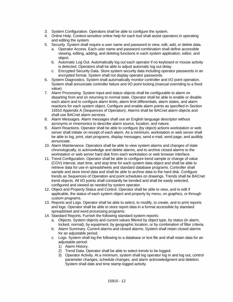
3. System Configuration. Operators shall be able to configure the system. 4. Online Help. Context-sensitive online help for each tool shall assist operators in operating
and editing the system. 5. Security. System shall require a user name and password to view, edit, add, or delete data.
a. Operator Access. Each user name and password combination shall define accessible viewing, editing, adding, and deleting functions in each system application, editor, and object.
b. Automatic Log Out. Automatically log out each operator if no keyboard or mouse activity is detected. Operators shall be able to adjust automatic log out delay.
c. Encrypted Security Data. Store system security data including operator passwords in an encrypted format. System shall not display operator passwords.
6. System Diagnostics. System shall automatically monitor controller and I/O point operation. System shall annunciate controller failure and I/O point locking (manual overriding to a fixed value).
7. Alarm Processing. System input and status objects shall be configurable to alarm on departing from and on returning to normal state. Operator shall be able to enable or disable each alarm and to configure alarm limits, alarm limit differentials, alarm states, and alarm reactions for each system object. Configure and enable alarm points as specified in Section 15910 Appendix A (Sequences of Operation). Alarms shall be BACnet alarm objects and shall use BACnet alarm services.
8. Alarm Messages. Alarm messages shall use an English language descriptor without acronyms or mnemonics to describe alarm source, location, and nature.
9. Alarm Reactions. Operator shall be able to configure (by object) actions workstation or web server shall initiate on receipt of each alarm. As a minimum, workstation or web server shall be able to log, print, start programs, display messages, send e-mail, send page, and audibly annunciate.
10. Alarm Maintenance. Operators shall be able to view system alarms and changes of state chronologically, to acknowledge and delete alarms, and to archive closed alarms to the workstation or web server hard disk from each workstation or web browser interface.
11. Trend Configuration. Operator shall be able to configure trend sample or change of value (COV) interval, start time, and stop time for each system data object and shall be able to retrieve data for use in spreadsheets and standard database programs. Controller shall sample and store trend data and shall be able to archive data to the hard disk. Configure trends as Sequences of Operation and point schedules on drawings. Trends shall be BACnet trend objects. All I/O points shall constantly be trended and shall be easily selected, configured and viewed as needed by system operator.
12. Object and Property Status and Control. Operator shall be able to view, and to edit if applicable, the status of each system object and property by menu, on graphics, or through custom programs.
13. Reports and Logs. Operator shall be able to select, to modify, to create, and to print reports and logs. Operator shall be able to store report data in a format accessible by standard spreadsheet and word processing programs.
14. Standard Reports. Furnish the following standard system reports: a. Objects. System objects and current values filtered by object type, by status (in alarm,
locked, normal), by equipment, by geographic location, or by combination of filter criteria. b. Alarm Summary. Current alarms and closed alarms. System shall retain closed alarms
for an adjustable period. c. Logs. System shall log the following to a database or text file and shall retain data for an
adjustable period: 1) Alarm History. 2) Trend Data. Operator shall be able to select trends to be logged. 3) Operator Activity. At a minimum, system shall log operator log in and log out, control
parameter changes, schedule changes, and alarm acknowledgment and deletion. System shall date and time stamp logged activity.
15910 - 13
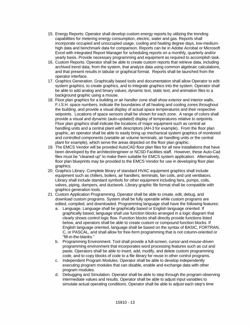
15. Energy Reports: Operator shall develop custom energy reports by utilizing the trending capabilities for metering energy consumption, electric, water and gas. Reports shall incorporate occupied and unoccupied usage, cooling and heating degree days, low-medium-high data and benchmark data for comparison. Reports can be in Adobe Acrobat or Microsoft Excel with integrated Report Manager for scheduling reports on a monthly, quarterly and/or yearly basis. Provide necessary programming and equipment as required to accomplish task.
16. Custom Reports. Operator shall be able to create custom reports that retrieve data, including archived trend data, from the system, that analyze data using common algebraic calculations, and that present results in tabular or graphical format. Reports shall be launched from the operator interface.
17. Graphics Generation. Graphically based tools and documentation shall allow Operator to edit system graphics, to create graphics, and to integrate graphics into the system. Operator shall be able to add analog and binary values, dynamic text, static text, and animation files to a background graphic using a mouse.
18. Floor plan graphics for a building or air handler zone shall show exterior and interior walls, F.I.S.H. space numbers, indicate the boundaries of all heating and cooling zones throughout the building, and provide a visual display of actual space temperatures and their respective setpoints. Locations of space sensors shall be shown for each zone. A range of colors shall provide a visual and dynamic (auto-updated) display of temperatures relative to setpoints. Floor plan graphics shall indicate the locations of major equipment such as central air handling units and a central plant with descriptors (AH-3 for example). From the floor plan graphic, an operator shall be able to easily bring up mechanical system graphics of monitored and controlled components (variable air volume terminals, air handling units or the central plant for example), which serve the areas depicted on the floor plan graphic.
19. The EMCS Vendor will be provided AutoCAD floor plan files for all new installations that have been developed by the architect/engineer or NCSD Facilities staff. However, these Auto-Cad files must be "cleaned up" to make them suitable for EMCS system application. Alternatively, floor plan blueprints may be provided to the EMCS Vendor for use in developing floor plan graphics.
20. Graphics Library. Complete library of standard HVAC equipment graphics shall include equipment such as chillers, boilers, air handlers, terminals, fan coils, and unit ventilators. Library shall include standard symbols for other equipment including fans, pumps, coils, valves, piping, dampers, and ductwork. Library graphic file format shall be compatible with graphics generation tools.
21. Custom Application Programming. Operator shall be able to create, edit, debug, and download custom programs. System shall be fully operable while custom programs are edited, compiled, and downloaded. Programming language shall have the following features: a. Language. Language shall be graphically based or English language oriented. If
graphically based, language shall use function blocks arranged in a logic diagram that clearly shows control logic flow. Function blocks shall directly provide functions listed below, and operators shall be able to create custom or compound function blocks. If English language oriented, language shall be based on the syntax of BASIC, FORTRAN, C, or PASCAL, and shall allow for free-form programming that is not column-oriented or "fill-in-the-blanks."
b. Programming Environment. Tool shall provide a full-screen, cursor-and-mouse-driven programming environment that incorporates word processing features such as cut and paste. Operators shall be able to insert, add, modify, and delete custom programming code, and to copy blocks of code to a file library for reuse in other control programs.
c. Independent Program Modules. Operator shall be able to develop independently executing program modules that can disable, enable and exchange data with other program modules.
d. Debugging and Simulation. Operator shall be able to step through the program observing intermediate values and results. Operator shall be able to adjust input variables to simulate actual operating conditions. Operator shall be able to adjust each step's time

15910 - 14
increment to observe operation of delays, integrators, and other time-sensitive control logic. Debugger shall provide error messages for syntax and for execution errors.
e. Conditional Statements. Operator shall be able to program conditional logic using compound Boolean (AND, OR, and NOT) and relational (EQUAL, LESS THAN, GREATER THAN, NOT EQUAL) comparisons.
f. Mathematical Functions. Language shall support floating-point addition, subtraction, multiplication, division, and square root operations, as well as absolute value calculation and programmatic selection of minimum and maximum values from a list of values.
g. Variables: Operator shall be able to use variable values in program conditional statements and mathematical functions. 1) Time Variables. Operator shall be able to use predefined variables to represent time
of day, day of the week, month of the year, and date. Other predefined variables or simple control logic shall provide elapsed time in seconds, minutes, hours, and days. Operator shall be able to start, stop, and reset elapsed time variables using the program language.
2) System Variables. Operator shall be able to use predefined variables to represent status and results of Controller Software and shall be able to enable, disable, and change setpoints of Controller Software as described in Controller Software section.
G. Environmental Indexing: Provide the required programming and software to indicate the
Environmental Index of each zone balancing energy efficiency and comfort. The index is expressed in percentage reflecting how close the zone temperature is to the effective heating and cooling setpoints. It shall be indicated by an analog graphic gauge using red segments to indicate poor environments, graduating to green as conditions improve and the index begins to approach 100%. Humidity and CO2 (zone or return air) shall also be incorporated if the points are available. This index shall also be trended during both occupied and unoccupied times.
H. Portable Operator's Terminal. Provide all necessary software to configure an IBM-compatible
laptop computer for use as a Portable Operator's Terminal. Operator shall be able to connect configured Terminal to the system network or directly to each controller for programming, setting up, and troubleshooting.
3.4 CONTROLLER SOFTWARE
A. Building and energy management application software shall reside and operate in system controllers. Applications shall be editable through operator workstation, web browser interface, or engineering workstation.
B. Scheduling. System shall provide the following schedule options as a minimum:
1. Weekly. Provide separate schedules for each day of the week. Each schedule shall be able to include up to 5 occupied periods (5 start-stop pairs or 10 events).
2. Exception. Operator shall be able to designate an exception schedule for each of the next 365 days. After an exception schedule has executed, system shall discard and replace exception schedule with standard schedule for that day of the week.
3. Holiday. Operator shall be able to define 24 special or holiday schedules of varying length on a scheduling calendar that repeats each year.
C. System Coordination. Operator shall be able to group related equipment based on function and
location and to use these groups for scheduling and other applications.
D. Remote Communication. System shall automatically contact operator workstation or server on receipt of critical alarms. If no network connection is available, system shall use a modem connection.
E. Demand Limiting
15910 - 15
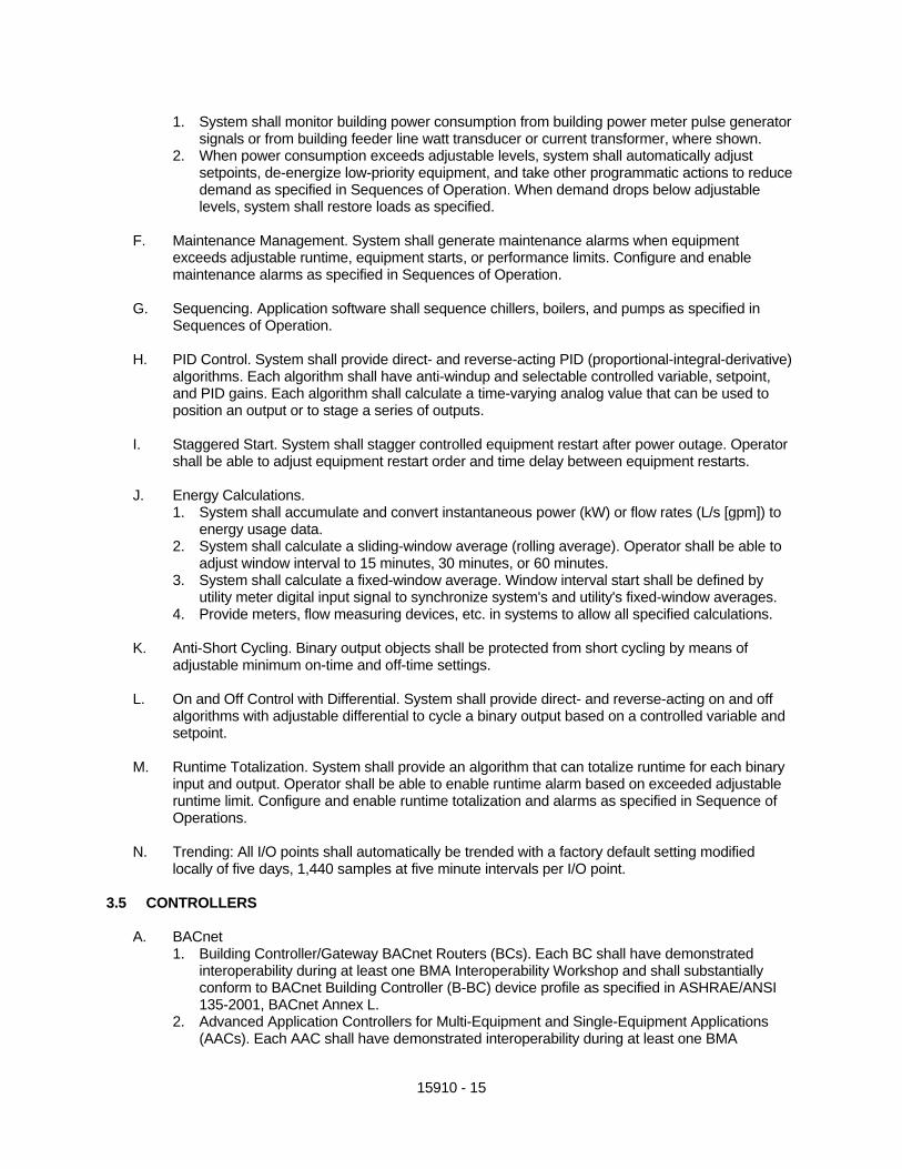
1. System shall monitor building power consumption from building power meter pulse generator signals or from building feeder line watt transducer or current transformer, where shown.
2. When power consumption exceeds adjustable levels, system shall automatically adjust setpoints, de-energize low-priority equipment, and take other programmatic actions to reduce demand as specified in Sequences of Operation. When demand drops below adjustable levels, system shall restore loads as specified.
F. Maintenance Management. System shall generate maintenance alarms when equipment
exceeds adjustable runtime, equipment starts, or performance limits. Configure and enable maintenance alarms as specified in Sequences of Operation.
G. Sequencing. Application software shall sequence chillers, boilers, and pumps as specified in
Sequences of Operation.
H. PID Control. System shall provide direct- and reverse-acting PID (proportional-integral-derivative) algorithms. Each algorithm shall have anti-windup and selectable controlled variable, setpoint, and PID gains. Each algorithm shall calculate a time-varying analog value that can be used to position an output or to stage a series of outputs.
I. Staggered Start. System shall stagger controlled equipment restart after power outage. Operator
shall be able to adjust equipment restart order and time delay between equipment restarts.
J. Energy Calculations. 1. System shall accumulate and convert instantaneous power (kW) or flow rates (L/s [gpm]) to
energy usage data. 2. System shall calculate a sliding-window average (rolling average). Operator shall be able to
adjust window interval to 15 minutes, 30 minutes, or 60 minutes. 3. System shall calculate a fixed-window average. Window interval start shall be defined by
utility meter digital input signal to synchronize system's and utility's fixed-window averages. 4. Provide meters, flow measuring devices, etc. in systems to allow all specified calculations.
K. Anti-Short Cycling. Binary output objects shall be protected from short cycling by means of
adjustable minimum on-time and off-time settings.
L. On and Off Control with Differential. System shall provide direct- and reverse-acting on and off algorithms with adjustable differential to cycle a binary output based on a controlled variable and setpoint.
M. Runtime Totalization. System shall provide an algorithm that can totalize runtime for each binary
input and output. Operator shall be able to enable runtime alarm based on exceeded adjustable runtime limit. Configure and enable runtime totalization and alarms as specified in Sequence of Operations.
N. Trending: All I/O points shall automatically be trended with a factory default setting modified
locally of five days, 1,440 samples at five minute intervals per I/O point. 3.5 CONTROLLERS
A. BACnet 1. Building Controller/Gateway BACnet Routers (BCs). Each BC shall have demonstrated
interoperability during at least one BMA Interoperability Workshop and shall substantially conform to BACnet Building Controller (B-BC) device profile as specified in ASHRAE/ANSI 135-2001, BACnet Annex L.
2. Advanced Application Controllers for Multi-Equipment and Single-Equipment Applications (AACs). Each AAC shall have demonstrated interoperability during at least one BMA

15910 - 16
Interoperability Workshop and shall substantially conform to BACnet Advanced Application Controller (B-AAC) device profile as specified in ASHRAE/ANSI 135-2001, BACnet Annex L.
3. Application Specific Controllers/Zone and Room Controllers (ASCs). Each ASC shall conform to BACnet Application Specific Controller (B-ASC) device profile as specified in ASHRAE/ANSI 135-2001, BACnet Annex L and shall be listed as a certified B-ASC in the BACnet Testing Laboratories (BTL) Product Listing.
4. BACnet Communication a. Each BC shall reside on or be connected to a BACnet network using ISO 8802-3
(Ethernet) Data Link/Physical layer protocol and BACnet/IP addressing. b. BACnet routing shall be performed by BCs or other BACnet device routers as necessary
to connect BCs to networks of AACs and ASCs. c. Each AAC and ASC shall reside on a BACnet network using the ARCNET or MS/TP
Data Link/Physical layer protocol.
B. Communication 1. Service Port. Each controller shall provide a service communication port for connection to a
Portable Operator's Terminal. Connection shall be extended to space temperature sensor ports where shown on drawings.
2. Signal Management. BC and ASC operating systems shall manage input and output communication signals to allow distributed controllers to share real and virtual object information and to allow for central monitoring and alarms.
3. Data Sharing. Each BC and AAC shall share data as required with each networked BC and AAC.
4. The system shall be capable of stand-alone operation in the event of communication failure. All I/O points specified for a piece of equipment shall be integral to its controller. Provide stable and reliable stand-alone control using default values or other method for values normally read over the network.
C. Environment: Controller hardware shall be suitable for anticipated ambient conditions.
1. Controllers used outdoors or in wet ambient conditions shall be mounted in waterproof enclosures and shall be rated for operation at -29°C to 60°C (-20°F to 140°F).
2. Controllers used in conditioned space shall be mounted in dust-protective enclosures and shall be rated for operation at 0°C to 50°C (32°F to 120°F).
3.6 DEVICES
A. Temperature sensors 1. Temperature sensors shall be Resistance temperature Device (RTD) or thermistor. 2. Duct sensors shall be single point or averaging as shown or required. 3. Immersion sensors shall be provided with a separable stainless steel well. Pressure rating of
well is to be consistent with the system pressure in which it is to be installed. The well must withstand the flow velocities in the pipe.
4. Space sensors shall be equipped with set point adjustment, override switch, display, and/or communication port as shown.
5. Provide matched temperature sensors for differential temperature measurement.
B. Relative Humidity Transmitters: Relative Humidity Transmitters shall use bulk polymer resistance technology for sensing. Transmitters shall be accurate within 2% and shall have true 4 to 20 mA analog output directly proportional to relative humidity. Provide case and associated hardware for space, duct, outside, or remote mounting as appropriate. Transmitters shall be General Eastern, Automation Components Inc. or pre-approved equal. 1. Room Humidity Sensors. Provide surface mount device for mounting on standard electrical
switch box. Cover shall match room temperature element. 2. Duct Humidity Sensors. Provide units with integral conduit mounting box and shield to
protect element from damage.

15910 - 17
C. Low Temperature Protection Thermostats: Provide low temperature protection thermostats of
automatic or manual-reset type as required by the sequence of operations, with sensing elements 8' or 20' in length. Provide thermostat designed to operate in response to coldest 1'-0" length of sensing element, regardless of temperature at other parts of element. 1. Support element properly to cover the entire duct width. 2. Provide separate thermostats for each 25 square feet of coil face area or fraction thereof. 3. Install sensor per manufacturers published recommendations. 4. Install all outside air intakes and ensure freeze protection of coils. 5. Provide low temperature protection in chilled and hot water system to bring on pumps to
circulate water when below system’s freezing point.
D. Flow Status Switches: Fan and pump flow status shall be monitored through motor current status switches in lieu of differential pressure switches. Current status switches shall have an adjustable setpoint and be capable of detecting belt/drive loss and motor failure. Switches shall be Veris Industries' or pre-approved equal model Hawkeye 705, 907 or 908 with LED status except that variable volume now applications must be model Hawkeye 907 (automatically compensates for variable volume effects including VFD’s). Control Contractors shall provide piping devices to allow flow indicators to be installed.
E. Current Monitoring: Provide analog input monitoring of motor KW/Amps for all major pieces of
HVAC equipment where required by the control drawings I/O summary. Transducers shall be by Veris Industries, Hawkeye model. Model number provided shall be applicable to the motor size and voltage.
F. Power Monitoring: Power monitoring of main switchgear or sub-power/lighting shall be Veris
Industries Networked Data Stream meters, model H8036 sized for panel loads. Communication shall be Modbus. Control contractor shall provide Third Party Interface Portal for BACnet communications.
G. Differential Pressure Transducers: Differential pressure transducers shall be as required with
internal signal conditioning and true analog output. The devices shall be Modus, Inc. (air) and Robinson Halpern or Auto Tran (water) or pre-approved equal. Provide pressure snubbers and isolation valves for water differential pressure applications to prevent damage due to pressure shocks and facilitate service and calibration.
H. Flow Measuring Devices: Provide turbine flow meters or differential pressure transmitters for
venturi type metering devices in the main chilled water to record the chilled water flow rate in GPM and totalize flow for at least a 24-hour period. Provide calculation value for tonnage on all chilled water generation equipment. Provide piping or orifices, venturis, etc. to allow installation of FMD’s.
I. CO2 Transmitters: CO2 transmitters shall use a non-dispersive infrared technology for sensing
CO2. Transmitters shall be accurate to +/- 50 PPM and shall have a true 4 to 20 mA analog output directly proportional over a range of 0 to 2,500 PPM. Provide room or duct mounted units as appropriate. Transmitters shall be Automation Components Inc., QEI, or pre-approved equal. Owner’s approval is required for all CO2 transmitters. Provide CO2 sensors in all assembly areas to allow limiting of outside air.
J. Relays: Relay contacts shall be rated for the application, with Form C contacts, enclosed in a
dust-proof enclosure. Relays shall have contacts with a minimum life span rating of one millionoperations. Relays shall be equipped with coil transient suppression. Provide additional relays as necessary to carry the intended load where load requirements exceed the 0.5 amp rating of EMCS Hardware Units. Open relays shall be IDEC, and relays in an enclosure shall be Functional Devices, RIB series or pre-approved equal.

15910 - 18
K. Contactors: Contactors shall be of the single coil, electrically operated, and electrically held type.
Contacts shall be double break silver-to-silver type protected from arcing contacts. Number of contacts and ratings shall be selected for application. Operating and release times shall be I 00 milliseconds or less. Contactors shall be equipped with coil transient suppression devices. Provide as necessary to carry the intended load where load requirements exceed the 0.5 amp rating of EMCS Hardware Units. Furnas or pre-approved equal.
L. The transformers shall be either 120/208/240/480 to 24/12 VAC as required by the voltage and/or
application. Provide a resettable circuit breaker at the secondary side of each transformer. Each transformer shall be UL approved class 2 unit with an operating ambient temperature range from -40 Deg. F. to 120 Deg. F. and a humidity level from 10% to 90% noncondensing.
M. Dampers:
1. Provide automatic control dampers in all outside air intakes and/or as indicated, with damper frames not less than formed 16-ga galvanized steel. Provide damper blades not less than formed 16-ga galvanized steel, with maximum blade width of 8". a. Secure blades to 1/2" diameter plated steel axles using zinc-plated hardware. Seal off
against spring stainless steel blade bearings. Provide blade bearings of nylon and provide thrust bearings at each end of every blade.
b. Parallel blade operation shall be used for all two position applications and opposed blade configurations for all modulating applications.
c. Performance Data 1) Capacity: Demonstrate capacity of damper to withstand HVAC system operating
conditions. a) Closed Position: Maximum pressure of 5 inches w.g. @ a 12 inch blade length. b) Open Position: Maximum air velocity of 2,000 feet per minute. c) Leakage: Maximum 3.7 cubic feet per minute per square foot at 1 inch w.g. for
all sizes 36 inches wide and above. 2) Pressure Drop: Maximum 0.07 inch w.g. at 1,500 feet per minute across 24 inch x
24 inch damper.
N. Chilled and Hot Water Control Valves: 1. Ball valves shall be used for all water applications where sizing permits. 2. Valves 1/2” through 3” shall be forged brass body with nickel plating, NPT screw type. The
operating range shall be 0�F to 212�F. control valves shall be furnished with a stainless steel ball & stem and fiberglass reinforced Teflon seats and seals.
3. The valves shall have an ISO type 4-bolt flange for mounting actuator in any orientation parallel or perpendicular to the pipe. A non-metallic thermal isolation adaptor shall separate the flange from the actuator with high temperature materials rated for continual use at greater than the application temperature. Valve assemblies without thermal isolation as described are not acceptable.
4. The isolation adaptor shall also provide stable direct coupled mechanical connection between the valve body and actuator and prevent lateral or rotational forces from affecting the stem and its packing O-rings.
5. All control valves shall have a TEFZEL flow-characterizing disc in the inlet of 2-way characterized control valves and in the control port of 3-way valves. Three-way valves shall be applicable for both mixing and diverting.
6. Control valves shall be two-way or three-way type for two-position or modulating service as shown. Valve CV shall be selected for a 3 to 5 psi pressure drop. Air handling unit water valves shall be sized for a pressure drop equal to the coil they serve, but not to exceed 5 psi.
7. The Control Contractor shall furnish all the control valves of the type indicated on the drawings for installation by the Mechanical Contractor.
8. Electronic control valve actuators shall be as manufactured, brand labeled, or distributed by Belimo or pre-approved equal.

15910 - 19
O. Butterfly Valves
1. Butterfly valves and/or actuators shall be as manufactured, brand labeled, or distributed by Belimo, or pre-approved equal.
2. Butterfly valves 2” to 30” shall have a fully lugged, drilled and tapped cast iron body. Flanges shall meet ANSI 150 standards. The one-piece body shall feature an extended neck allowing sufficient clearance for flanges and 2” of piping insulation. The disc shall be 304 stainless steel and provide bubble-tight close off for water or 50% glycol applications.
3. The 2” through 6” valves shall be rated for a maximum of 50-psi close off using standard Belimo actuators. Valves 2” through 12” shall be available in 50 or 200 pound close off as required by the application. Valves 14” through 30” shall be rated at 150 psi close off.
4. Actuators shall be applied according to the manufacturer’s specifications.
P. Damper and Valve Actuators 1. Actuators shall be fully modulating/proportional, pulse width, tri-state, or two position as
required and be factory or field selectable. Actuators shall provide a selectable feedback voltage and have visual position indications. Actuators shall operate in sequence with other devices if required.
2. Actuators shall be available to operate on 24 or 120 VAC, or 24 VDC and Class 2 wiring as dictated by the application. Power consumption shall not exceed 10 VA for AC, including 120 VAC actuators, and 8 watts for DC applications.
3. Actuators shall have electronic overload protection or digital rotation sensing circuitry to prevent actuator damage throughout the entire rotation. End switches to deactivate the actuator at the end of rotation or magnetic clutches are not acceptable.
4. Manufacturer shall provide a five (5) year unconditional warranty from date of Final Acceptance.
5. Each valve shall fail safe open or closed to the coil as indicated in the sequence of operation or to prevent freezing.
6. The valve actuator shall be capable of providing the minimum torque required for proper valve close off to exceed the dead head pressure of the largest pump within the system, or 60 psi, which ever is greater.
7. Electronic control damper actuators shall be as manufactured, brand labeled, or distributed by Belimo or pre-approved equal.
Q. Environmental Conditions: All equipment shall operate under ambient environmental conditions
of 35 degrees to 122 degrees F dry bulb and 10 to 95 percent RH noncondensing. Sensors and control elements shall operate under the ambient environmental temperature, pressure, humidity, and vibration conditions specified or normally encountered for the installed location.
R. System Accuracy: The system shall maintain an end-to-end accuracy, as listed for the
applications specified.
Table 1 - Reporting Accuracy
Measured Variable Reported Accuracy
Space Temperature ±0.5ºF
Ducted Air ±0.5ºF
Outside Air ±0.5ºF
Dew Point ±1ºF
Water Temperature ±0.5ºF

15910 - 20
Delta-T ±0.5ºF
Relative Humidity ±5% RH
Water Flow ±2% of full scale
Airflow (terminal) ±10% of full scale (see Note 1)
Airflow (measuring stations) ±5% of full scale
Airflow (pressurized spaces) ±3% of full scale
Air Pressure (ducts) ±0.1 in. w.g.
Air Pressure (space) ±0.02 in. w.g.
Water Pressure ±2% of full scale (see Note 2)
Electrical (A, V, W, Power Factor) 5% of reading (see Note 3)
Carbon Monoxide (CO) ±5% of reading
Carbon Dioxide (CO2) ±50 ppm
Note 1: 10%-100% of scale
Note 2: For both absolute and differential pressure
Note 3: Not including utility-supplied meters
Table 2 - Control Stability and Accuracy
Controlled Variable Control Accuracy Range of Medium
Air Pressure ±0.2 in. w.g. 0-6 in. w.g.
Airflow ±10% of full scale
Space Temperature ±1.0ºF
Duct Temperature ±1.5ºF
Humidity ±5% RH
Fluid Pressure ±1.5 psi 1-150 psi
3.7 WIRE, CABLE, CONDUIT AND POWER SUPPLIES
A. Conduit: Provide conduit for all wire and cable in accordance with Division 16. The Contractor shall take particular care to ensure that conduit run underground is properly sealed to prevent water intrusion and shall have minimum cover of 18 inches.
15910 - 21
B. The EMCS Vendor shall take particular care to provide shielded plenum rated cable in all plenums whether in conduit or not. Failure to do so will require replacement.
C. Wiring shall be continuous with no joints except at equipment terminations. Drain wire shall be
continuous and grounded as per manufactures recommendations.
D. Transmitter Wiring: Transmitter wiring, or other 4-20 ma. signaling device wiring shall be continuous from the device to its Controller Unit. Drain wire shall be continuous and grounded at the Controller Unit only. Transmitter wiring shall be West Penn 303 or pre-approved equal.
E. Power Supplies: The EMCS Vendor shall be responsible for providing all power supplies
required, including control transformers, and any connections to building electrical system which are required and are not explicitly shown on the Electrical or Mechanical drawings.
Control Contractor shall provide and coordinate the HVAC and EMCS controls with the Project Licensed Electrical Contractor in order that the electrical power for controls is proved. Equipment such as unit ventilators, blower coils, and fan terminal units can receive control power from the same power supply that is brought to the unit for the fan. However, variable air volume boxes, wall mounted control panels serving air handling units, building gateway router, etc. require a 120 volt power supply to be brought to the controls. The power supply brought to the controls shall be from 120 volt circuits which are dedicated for controls. The dedicated circuit shall be sized to provide a minimum of 100VA to each variable air volume box and 200 VA to each wall mounted control panel.
F. Fiber optic cabling between buildings shall be furnished and installed under Electrical
Division/Section and shall not be provided by EMCS contractor.
G. Termination of fiber cabling in buildings shall be by EMCS Contractor on the EMCS control panel located in Communications Room. Control Contractor shall pick up controls at fiber termination and provide all equipment to route throughout all buildings and to all HVAC equipment and DDC panels.
PART 4 - EXECUTION 4.1 THE EMCS VENDOR SHALL BE RESPONSIBLE FOR:
A. Providing and Installing all system components in accordance with the manufacturers recommendations.
B. Providing all input and control devices and necessary interconnections of wire, cable, fiber and
conduit within the building.
C. System startup, commissioning and adjustments required for a complete operable system. He shall coordinate with the EDP, and Mechanical Contractor to insure the system operates as required.
D. Provide operations and maintenance manuals covering the entire EMCS.
4.2 INSTALLATION
A. General. Install system and materials in accordance with manufacturer's instructions and roughing-in drawings, and details on drawings. Mount controllers at convenient locations and heights.

15910 - 22
B. All installation of the EMCS shall be performed by mechanics, electricians and technicians in the direct supervision of the system supplier. Coordinate installation with all other affected trades. Provide necessary project management personnel for this section.
4.3 ELECTRICAL INSTALLATION
A. Coordination of the EMCS design and installation with the EDP and Owner.
B. Providing shop drawings and a complete list of all EMCS hardware including input and control devices required for the project with the source of supply clearly indicated.
C. The EMCS Vendor shall be responsible for providing all wire, cable, and conduit required by this
section inside the buildings and to outside EMCS devices. All wiring and cable shall be approved for its intended use and shall be run in conduit. All wire, cable and conduit shall be installed to conform with Division 16 requirements and the National Electrical Code, NFPA 70 by a licensed Electrical Contractor where voltage is 50 volts or higher per NEC. Plenum cable may be run above ceilings, concealed, in existing areas only unless noted on plans to be in conduit in all areas.
D. Wire shall be labeled at the control panel. Labels shall be Brady PWM Series or pre-approved
equal, and shall be marked in accordance with descriptors or abbreviations used on the control drawings.
E. All wiring, conduit and devices pertaining to the fire alarm system shall be provided under Division
16 with the following exceptions: 1. Provide identified terminals in the motor control circuit on those air handling systems requiring
automatic shut down from the fire alarm system. Coordinate this with the fire alarm system tradesman who will connect to these terminals and interface with the fire alarm system.
2. Duct mounted smoke detectors shall be physically mounted under Division 23 by the Mechanical Contractor, although all wiring and conduit shall be provided under Division 16. EMCS Contractor shall connect to EMCS for alarm and system shutdown.
F. Provide all internal control wiring in starters under Section 15910. Final installation of the starter
and the provision of all power wiring, conduit and terminations shall be accomplished under Division 16. Provide all final control wiring and conduit to the starter under Section 15910.
G. Providing operation and maintenance manuals covering equipment and software provided and
providing framed control drawings. 4.4 INSTALLATION OF SENSORS
A. Install sensors in accordance with the manufacturer's recommendations.
B. Mount sensors rigidly and adequately for the environment within which the sensor operates.
C. Room temperature sensors shall be installed on concealed junction boxes properly supported by the wall framing.
D. Relocate space thermostats/sensors if required due to draft, interference with cabinets,
chalkboards, etc., or improper sensing.
E. All wires attached to sensors shall be air sealed in their raceways or in the wall to stop air transmitted from other areas affecting sensor readings.

15910 - 23
F. Sensors used in mixing plenums and hot and cold decks shall be of the averaging type. Averaging sensors shall be installed in a serpentine manner vertically across the duct. Each bend shall be supported with a capillary clip.
G. Low-limit sensors used in mixing plenums shall be installed in a serpentine manner horizontally
across duct. Each bend shall be supported with a capillary clip. Provide 3 m of sensing element for each 1 m 2 (1 ft of sensing element for each 1 ft 2) of coil area.
H. All pipe-mounted temperature sensors shall be installed in wells. Install all liquid temperature
sensors with heat-conducting fluid in thermal wells.
I. Install outdoor air temperature sensors on north wall, complete with sun shield at designated location.
4.5 DIFFERENTIAL AIR STATIC PRESSURE
A. Supply Duct Static Pressure: Pipe the high-pressure tap to the duct using a pitot tube. Make pressure tap connections in accordance with the manufacturers instructions.
B. Return Duct Static Pressure: Pipe the high-pressure tap to the duct using a pitot tube. Make
pressure tap connections in accordance with the manufacturers instructions.
C. Building Static Pressure: Pipe the low-pressure port of the pressure sensor to the static pressure port located on the outside of the building through a high-volume accumulator. Pipe the high-pressure port to a location behind a thermostat cover.
D. The piping to the pressure ports on all pressure transducers shall contain a capped test port
located adjacent to the transducer.
E. All pressure transducers, other than those controlling VAV boxes, shall be located in field device panels, not on the equipment monitored or on ductwork. Mount transducers in a vibration free location accessible for service without use of ladders or special equipment.
F. All air and water differential pressure sensors shall have gauge tees mounted adjacent to the
taps. Water gauges shall also have shutoff valves installed before the tee. 4.6 CONTROL WIRING
A. Provide all electrical work required as an integral part of the digital control work. Install a complete wiring system for the temperature control system including wire, conduit and miscellaneous materials as required for mounting and connecting control devices. Conceal wiring except in mechanical rooms and areas where other conduit and piping are exposed. All wiring to sensors and bus connections is low voltage and should be in accordance with local regulations and the National Electrical Code. Control Contractor shall pick up all connections at fiber cable termination rack.
B. Conduit: Provide conduit for all wire and cable in accordance with Division 16. The Contractor
shall take particular care to ensure that conduit run underground is properly sealed to prevent water intrusion. Water intrusion will require conduit re-installation.
C. The Contractor shall take particular care to provide shielded cable as required. Failure to do so
will require replacement at the Contractor's expense.
D. All wiring that is required to go underground must be rated for that use and approved.

15910 - 24
E. Install equipment, piping, and wiring/raceway parallel to building lines (i.e., horizontal, vertical, and parallel to walls) wherever possible.
F. Verify integrity of all wiring to ensure continuity and freedom from shorts and grounds.
G. All equipment, installation, and wiring shall comply with acceptable industry specifications and
standards for performance, reliability, and compatibility and be executed in strict adherence to local codes and standard practices.
H. All control and interlock wiring shall comply with national and local electrical codes and Division
16 of this specification. Where the requirements of this section differ from those in Division 16, the requirements of this section shall take precedence.
I. All NEC Class 1 (line voltage) wiring shall be UL Listed in approved raceway according to NEC
and Division 16 requirements.
J. All low-voltage wiring shall meet NEC Class 2 requirements. (Low-voltage power circuits shall be subfused when required to meet Class 2 current limit.)
K. Do not install Class 2 wiring in raceway containing Class 1 wiring. Boxes and panels containing
high voltage wiring and equipment may not be used for low-voltage wiring except for the purpose of interfacing the two (e.g., relays and transformers).
L. Do not install wiring in raceway containing tubing.
M. All wire-to-device connections shall be made at a terminal block or terminal strip. All wire-to-wire
connections shall be at a terminal block.
N. All wiring within enclosures shall be neatly bundled and anchored to permit access and prevent restriction to devices and terminals.
O. All wiring shall be installed as continuous lengths, with no splices permitted between termination
points.
P. Size of raceway and size and type of wire shall be the responsibility of the contractor, in keeping with the manufacturer's recommendations and NEC requirements, except as noted elsewhere.
Q. Include one pull string in each raceway.
R. Control and status relays are to be located in designated enclosures only. These enclosures
include packaged equipment control panel enclosures unless they also contain Class 1 starters.
S. Secure raceways with raceway clamps fastened to the structure and spaced according to code requirements. Raceways and pull boxes may not be hung on flexible duct strap or tie rods. Raceways may not be run on or attached to ductwork.
T. Adhere to this specification's Division 16 requirements where raceway crosses building expansion
joints.
U. The Contractor shall terminate all control and/or interlock wiring related to the scope of work of this section and shall maintain updated (as-built) wiring diagrams with terminations identified at the job site.
V. Flexible metal raceways and liquid-tight, flexible metal raceways shall not exceed 3 ft in length
and shall be supported at each end. Flexible metal raceway less than ½ in. electrical trade size

15910 - 25
shall not be used. In areas exposed to moisture, including chiller and boiler rooms, liquid-tight, flexible metal raceways shall be used.
W. Raceway must be rigidly installed, adequately supported, properly reamed at both ends, and left
clean and free of obstructions. Raceway sections shall be joined with couplings (according to code). Terminations must be made with fittings at boxes, and ends not terminating in boxes shall have bushings installed.
4.7 WARNING LABELS
A. Permanent warning labels shall be affixed to all equipment that can be automatically started by the DDC system. 1. Labels shall use white lettering (12-point type or larger) on a red background. 2. Warning labels shall read as follows:
C A U T I O N
This equipment is operating under automatic control and may start or stop at any time without warning. Switch disconnect to "Off" position before
servicing.
B. Permanent warning labels shall be affixed to all motor starters and all control panels that are connected to multiple power sources utilizing separate disconnects. 1. Labels shall use white lettering (12-point type or larger) on a red background. 2. Warning labels shall read as follows:
C A U T I O N
This equipment is fed from more than one power source with separate disconnects. Disconnect all power sources before servicing.
4.8 IDENTIFICATION OF HARDWARE AND WIRING
A. All wiring and cabling, including that within factory fabricated panels, shall be labeled at each end within 2 in. of termination. Labels shall be Brady PWM Series or pre-approved equal, and shall be marked in accordance with descriptors or abbreviations used on the control drawings.
B. Permanently label or code each point of field terminal strips to show the instrument or item
served.
C. Identify control panels with minimum ½ in. letters on laminated plastic nameplates.
D. Identify all other control components with permanent labels. All plug-in components shall be labeled such that removal of the component does not remove the label.
E. Identify room sensors relating to terminal box or valves with nameplates.
F. Manufacturers' nameplates and UL labels are to be visible and legible after equipment is
installed.

15910 - 26
G. Identifiers shall match record documents.
4.9 SOFTWARE INSTALLATION
A. General: Install all components and load all system software in accordance with manufacturer's recommendations.
B. Load and debug all software required for an operational EMCS, including data base,
operational parameters, and system and applications programs. Load and debug all control software necessary to implement all sequences of operation and as shown on the drawings.
PART 5 - CONTROL SYSTEM DEMONSTRATION AND ACCEPTANCE 5.1 DEMONSTRATION
A. Prior to acceptance, the control system shall undergo a series of performance tests to verify operation and compliance with this specification. These tests shall occur after the Contractor has completed the installation, started up the system, and performed his/her own tests.
B. The tests described in this section are to be performed in addition to the tests that the
contractor performs as a necessary part of the installation, start-up, and debugging process. The engineer (EDP) will be present to observe and review these tests. The EDP shall be notified at least 10 days in advance of the start of the testing procedures.
C. The EMCS Vendor shall provide at least two persons equipped with two-way communication
and shall demonstrate actual field operation of each control and sensing point for all modes of operation including day, night, occupied, unoccupied, fire/smoke alarm, seasonal changeover, and power failure modes. The purpose is to demonstrate the calibration, response, and action of every point and system. Any test equipment required to prove the proper operation shall be provided by and operated by the contractor.
D. As each control input and output is checked, a log shall be completed showing the date,
technician's initials, and any corrective action taken or needed.
E. Demonstrate compliance with sequences of operation through all modes of operation.
F. Demonstrate complete operation of operator interface.
G. Additionally, the following items shall be demonstrated: 1. DDC loop response. The contractor shall supply trend data output in a graphical form
showing the step response of each DDC loop. The test shall show the loop's response to a change in set point, which represents a change of actuator position of at least 25% of its full range. The sampling rate of the trend shall be from 10 seconds to 3 minutes, depending on the speed of the loop. The trend data shall show for each sample the set point, actuator position, and controlled variable values. Any loop that yields unreasonably under-damped or over damped control shall require further tuning by the EMCS Vendor.
2. Interface to the building fire alarm system. 3. Trend logs for each system that indicate set points, operating points, valve positions, and
other data as specified in the Points List provided with each Sequence of Operation. These logs shall cover three 48-hour periods and have a sample frequency of not more than 10 minutes or as specified on the Points List. The logs shall be accessible through the system's user interface and retrievable for use in an excel spreadsheet.

15910 - 27
H. Any tests that fail to demonstrate the operation of the system shall be repeated at a later date. The EMCS Vendor shall be responsible for any necessary repairs or revisions to the hardware or software to successfully complete all tests.
5.2 CONTROL SYSTEM CHECKOUT AND TESTING
A. Check and test all systems for shorts, ground, continuity and finally for proper functioning and operation. A certified factory trained technician, employed by the controls representative shall perform final connections of equipment, testing of the system and any other necessary adjustments.
B. After all EMCS work has completed and put into operation, subject each system to an operating
test under design conditions to insure proper sequence and operation throughout the range of operation. Make adjustments as required to insure proper functioning of all systems.
C. The EMCS Vendor shall provide personnel, tools and equipment and assist the Test and
Balance Contractor in making any final adjustments. The EMCS Vendor is responsible to ensure all final Test and Balance numbers are installed for each device.
D. Start-up Testing: All testing listed in this article shall be performed by the contractor and shall
make up part of the necessary verification of an operating control system. This testing shall be completed before the owner's representative is notified of the system demonstration.
E. Acceptance Test: An acceptance test shall be performed where a random number of I/O points
will be selected, physically inspected and tested in the presence of at least one of the following: EDP, Owner or Owner Representative.
F. Checkout: Prior to requesting final acceptance of the system, demonstrate to the Engineer that
all requirements of this Section have been fully complied with.
G. The contractor shall furnish all labor and test apparatus required to calibrate and prepare for service of all instruments, controls, and accessory equipment furnished under this specification.
H. Verify that all control wiring is properly connected and free of all shorts and ground faults. Verify
that terminations are tight.
I. Enable the control systems and verify calibration of all input devices individually. Perform calibration procedures according to manufacturers' recommendations.
J. Verify that all binary output devices (relays, solenoid valves, two-position actuators and control
valves, magnetic starters, etc.) operate properly and that the normal positions are correct.
K. Verify that all analog output devices (I/Ps, actuators, etc.) are functional, that start and span are correct, and that direction and normal positions are correct. The contractor shall check all control valves and automatic dampers to ensure proper action and closure. The contractor shall make any necessary adjustments to valve stem and damper blade travel.
L. Verify that the system operation adheres to the sequences of operation. Simulate and observe
all modes of operation by overriding and varying inputs and schedules. Tune all PID loops and any other control routines that require tuning.
M. Alarms and Interlocks
1. Check each alarm separately by including an appropriate signal at a value that will trip the alarm.

15910 - 28
2. Interlocks shall be tripped using field contacts to check the logic, as well as to ensure that the fail-safe condition for all actuators is in the proper direction.
3. Interlock actions shall be tested by simulating alarm conditions to check the initiating value of the variable and interlock action.
N. Any tests that cannot be performed due to circumstances beyond the control of the EMCS
Vendor may be exempt from the completion requirements if stated as such in writing by the engineer. Such tests shall then be performed as part of the warranty.
5.3 FINAL ADJUSTMENT OF EQUIPMENT
A. The EMCS Vendor shall be responsible for control system start-up, and shall perform all checkout, calibration and testing to insure proper system operation.
B. Final adjustment shall be performed by specially trained personnel in the direct employ of the
manufacturer of the EMCS Vendor.
C. Provide system CD-Rom back-ups at all workstations and final manuals. 5.4 GUARANTEE
A. Labor and materials for routine maintenance and service on a quarterly basis for the control system specified shall be warranted free from defects for a minimal period of 5 years after final completion and Owner receives beneficial use of the system. Control system failures during the 5-year warranty period shall be adjusted, repaired or replaced at no additional cost or reduction in service to the Owner. The contractor shall respond to the Owner’s request for warranty service online within 1 hour of complaint or onsite within 4 hours during normal business hours.
B. All work shall have a single warranty date, even when the Owner has received beneficial use due to an early system start-up. If the work specified is split into multiple contracts or a multi-phase contract, then each contract or phase shall have a separate warranty start date and period.
C. Operator workstation software, project-specific software, graphic software, database software
and firmware updates that resolve known software deficiencies as identified by the contractor shall be provided at no charge during the warranty period. Any upgrades or functional enhancements associated with the above-mentioned items also can be provided during the warranty period for an additional charge to the Owner. Written authorization by the Owner must, however, be granted prior to the installation of any of the above mentioned items.
D. Furnish a letter that states the control system has been tested, checked for operation and
calibration, commissioned, and the system is operating as designed. The system shall be fully programmed for temperature, humidity, and time of day as well as occupancy scheduled.
5.5 OWNERSHIP OF PROPRIETARY MATERIAL
A. Project-specific software and documentation shall become Owner's property. This includes, but is not limited to: 1. Graphics 2. Software to build graphics and program changes 3. Record drawings 4. Databases and Programs 5. Application programming code

15910 - 29
6. Documentation for complete operational manuals END OF SECTION