SECTION 11483 LIFT STATIONS DIESEL FUEL STORAGE AND PIPING ... · 16.03.2018 · A. Exterior...
26
01/22/2018 CoO WASTEWATER Division 11 Utilities Section 11483 Lift Stations Diesel Fuel Storage And Piping System Page 1 of 26 SECTION 11483 LIFT STATIONS DIESEL FUEL STORAGE AND PIPING SYSTEM This specification details the requirements for the diesel storage and piping system. Specification 16621 Lift Stations Standby Diesel Generator Set details the requirements of the emergency generator, generator accessories, and automatic transfer switch. Section Product Description 11483-1.01. Scope; 11483-1.02. References; 11483-1.03. Submittals; 11483-1.04. Quality Assurance; 11483-1.05. Delivery, Storage and Handling; 11483-1.06. Spare Parts; 11483-2.01. General; 11483-2.02. Aboveground Storage Tank (AST); 11483-2.03. AST Accessories; 11483-2.04. AST Accessories, Vent Cap; 11483-2.05. AST Accessories, Emergency Vent; 11483-2.06. AST Accessories, Isolation and Ball Valves; 11483-2.07. AST Accessories, Anti-Siphon Valve; 11483-2.08. AST Accessories, Overfill Protection Stop Valve; 11483-2.09. AST Accessories, Double Poppet Foot Valve; 11483-2.10. AST Accessories, External AST Emergency Shutoff Valve; 11483-2.11. Pipe and Fittings; 11483-2.12. Pipe and Fittings, Exterior Primary Piping, Fittings and Connections; 11483-2.13. Pipe and Fittings, Fiberglass Reinforced Plastic (FRP) Secondary Containment Piping, Fittings and Connections; 11483-2.14. Pipe and Fittings, Interior Aboveground Fuel, Vent Piping and Fittings; 11483-2.15. Pipe and Fittings, Exterior Flexible Piping at Tank, Containment Sumps and Equipment; 11483-2.16. Pipe and Fittings, Interior Flexible Piping at Tank, Containment Sumps and Equipment; 11483-2.17. Pipe and Fittings, Piping Transitions, Sleeves and Supports; 11483-2.18. Pipe and Fittings, Hangers and Straps; 11483-2.19. Pipe and Fittings, Support & Framing Channels and Fittings; 11483-2.20. Pipe and Fittings, Anchors; 11483-2.21. Pipe and Fittings, Miscellaneous Hardware; 11483-2.22. Pipe and Fittings, Thread Sealant; 11483-2.23. Instrumentation & Leak Monitoring; 11483-2.24. Instrumentation & Leak Monitoring, Visible Level Monitoring; 11483-2.25. Instrumentation & Leak Monitoring, Magnetostrictive Level Sensor; 11483-2.26. Instrumentation & Leak Monitoring, Tank Monitoring System; 11483-2.27. Instrumentation & Leak Monitoring, Tank Level Detection Sensors; 11483-2.28. Instrumentation & Leak Monitoring, Double Wall Interstitial Leak Sensor; 11483-2.29. Diesel Fuel Day Tank; 11483-2-30. Diesel Fuel Day Tank (Generator) Supply Line Fuel/Water Separator; 11483-2-31. Diesel Fuel Day Tank (Generator) Fuel Supply Line Solenoid Valve; 11483-2-32. Painting, Coatings and Labeling; 11483-3.01. General; Lift Station Nos. 49, 55, & 122 Fuel Tank Replacement & Improvements IFB18-0213
Transcript of SECTION 11483 LIFT STATIONS DIESEL FUEL STORAGE AND PIPING ... · 16.03.2018 · A. Exterior...

01/22/2018 CoO WASTEWATER Division 11 Utilities
Section 11483 Lift Stations Diesel Fuel Storage And Piping System
Page 1 of 26
SECTION 11483 LIFT STATIONS DIESEL FUEL STORAGE AND PIPING SYSTEM
This specification details the requirements for the diesel storage and piping system. Specification 16621 Lift Stations Standby Diesel Generator Set details the requirements of the emergency generator, generator accessories, and automatic transfer switch.
Section Product Description 11483-1.01. Scope; 11483-1.02. References; 11483-1.03. Submittals; 11483-1.04. Quality Assurance; 11483-1.05. Delivery, Storage and Handling;11483-1.06. Spare Parts;
11483-2.01. General; 11483-2.02. Aboveground Storage Tank (AST);11483-2.03. AST Accessories; 11483-2.04. AST Accessories, Vent Cap;11483-2.05. AST Accessories, Emergency Vent;11483-2.06. AST Accessories, Isolation and Ball Valves;11483-2.07. AST Accessories, Anti-Siphon Valve;11483-2.08. AST Accessories, Overfill Protection Stop Valve;11483-2.09. AST Accessories, Double Poppet Foot Valve;11483-2.10. AST Accessories, External AST Emergency Shutoff Valve;11483-2.11. Pipe and Fittings; 11483-2.12. Pipe and Fittings, Exterior Primary Piping, Fittings and Connections; 11483-2.13. Pipe and Fittings, Fiberglass Reinforced Plastic (FRP) Secondary Containment Piping, Fittings
and Connections; 11483-2.14. Pipe and Fittings, Interior Aboveground Fuel, Vent Piping and Fittings; 11483-2.15. Pipe and Fittings, Exterior Flexible Piping at Tank, Containment Sumps and Equipment;11483-2.16. Pipe and Fittings, Interior Flexible Piping at Tank, Containment Sumps and Equipment;11483-2.17. Pipe and Fittings, Piping Transitions, Sleeves and Supports;11483-2.18. Pipe and Fittings, Hangers and Straps;11483-2.19. Pipe and Fittings, Support & Framing Channels and Fittings;11483-2.20. Pipe and Fittings, Anchors;11483-2.21. Pipe and Fittings, Miscellaneous Hardware;11483-2.22. Pipe and Fittings, Thread Sealant;11483-2.23. Instrumentation & Leak Monitoring;11483-2.24. Instrumentation & Leak Monitoring, Visible Level Monitoring;11483-2.25. Instrumentation & Leak Monitoring, Magnetostrictive Level Sensor; 11483-2.26. Instrumentation & Leak Monitoring, Tank Monitoring System;11483-2.27. Instrumentation & Leak Monitoring, Tank Level Detection Sensors; 11483-2.28. Instrumentation & Leak Monitoring, Double Wall Interstitial Leak Sensor; 11483-2.29. Diesel Fuel Day Tank; 11483-2-30. Diesel Fuel Day Tank (Generator) Supply Line Fuel/Water Separator; 11483-2-31. Diesel Fuel Day Tank (Generator) Fuel Supply Line Solenoid Valve; 11483-2-32. Painting, Coatings and Labeling;
11483-3.01. General;
Lift Station Nos. 49, 55, & 122 Fuel Tank Replacement & Improvements IFB18-0213

01/22/2018 CoO WASTEWATER Division 11 Utilities
Section 11483 Lift Stations Diesel Fuel Storage And Piping System
Page 2 of 26
11483-3.02. Installation of AST; 11483-3.03. Installation of Fuel Piping;11483-3.04. Installation of Flexible Fuel Piping;11483-3.05. Installation of Day Tank;11483-3.06. Installation of Leak Sensors;11483-3.07. Signage; 11483-3.08. Adjusting and Cleaning;11483-3.09. Testing; 11483-3.10. Startup Services; 11483-3.11. Warranty;
Lift Station Nos. 49, 55, & 122 Fuel Tank Replacement & Improvements IFB18-0213

01/22/2018 CoO WASTEWATER Division 11 Utilities
Section 11483 Lift Stations Diesel Fuel Storage And Piping System
Page 3 of 26
PART 1 - GENERAL 11483-1.01. Scope (Project) A. The work of this section includes all labor, materials, equipment and supervision required for the installation and testing of the diesel fuel storage and piping system complete and ready for operation compatible with the existing standby generator equipment already located on each lift station site. Contractor shall coordinate with each existing generator manufacturer’s and provide all equipment as required to provide a fully operational system.
B. The diesel fuel storage and piping system shall be capable of storing enough fuel to run the emergency standby generator at full (100%) load for 120 consecutive hours (five (5) full days).
C. The fuel storage tank must be located to ensure the fuel supply piping length does not exceed 20-feet and/or confirmed acceptable by the existing generators’ MANUFACTURERs or a fuel day tank shall be required as indicated on drawings. .
D. The CONTRACTOR shall have the following minimum qualifications: 1. Be defined, registered and licensed by the State of Florida Department of Environment Protection
(FDEP) as a Certified Pollutant Storage System Contractor (CPSSC), (provide a copy of the license with the equipment submittal);
2. Provide the OWNER with acceptable evidence of current Pollution Liability insurance coverage (one million dollars, $1,000,000 minimum);
3. Provide the documentation that illustrates ability to perform the work
E. The CONTRACTOR shall furnish for the complete and ready for operation, the installation, connection, testing and commissioning of the new fuel system comprised of the following:
1. Aboveground storage tank (AST); 2. AST MANUFACTURER recommended reinforced concrete pad per ASTM A615 with anchors and
straps at various locations in accordance with FDEP 62-762 FAC; 3. 50 or 100-gallon Day tank; 4. Fuel supply and return piping with secondary containment; 5. Fuel Tank Level sensor for remote monitoring; 6. Fuel Tank Monitoring System; 7. Proper and required AST signage; 8. Remedy and make good all defective workmanship and materials related to this project and pay for any
damage to other work resulting there-from, which appear within the warranty period, providing such defects are not clearly due to abuse or misuse by the OWNER;
9. The work shall be in accordance with FDEP Rules 62-762 of the Florida Administrative Code (FAC), per MANUFACTURER’s recommendations and according to this specification.
F. All work shall conform to the applicable requirements of all federal, state and local laws, ordinances, rules andregulations pertaining to the performance of the work specified herein. Where the requirements of such agenciesare more stringent than specified herein, abide by such requirements and consider this specification as supplementary to those requirements;
Lift Station Nos. 49, 55, & 122 Fuel Tank Replacement & Improvements IFB18-0213

01/22/2018 CoO WASTEWATER Division 11 Utilities
Section 11483 Lift Stations Diesel Fuel Storage And Piping System
Page 4 of 26
G. All work shall conform to the following regulatory agencies and their applicable requirements: 1. U.S. Environmental Protection Agency (USEPA); 2. FDEP Rules 62-762 FAC; 3. All work within Orange County shall be coordinated with the Petroleum Storage Group, (407) 836-1403,
Orange County Department of Environmental Protection (OCDEP); 4. NFPA® 30 – Flammable and Combustible Liquids Code; 5. NFPA® 37 - Standard for the Installation and Use of Stationary Combustion Engines and Gas Turbines; 6. Florida Fire Prevention Code; 7. Florida Building Code; 8. All electrical work shall conform to the applicable requirements of the National Electric Code® (NEC®); 9. The AST shall meet the current requirements of Underwriters Laboratories (UL) 142 and 1709; 10. All components of the fuel storage & piping system shall be UL Listed;
Lift Station Nos. 49, 55, & 122 Fuel Tank Replacement & Improvements IFB18-0213

01/22/2018 CoO WASTEWATER Division 11 Utilities
Section 11483 Lift Stations Diesel Fuel Storage And Piping System
Page 5 of 26
H. The CONTRACTOR shall obtain all permits, licenses, certificates and coordination efforts, or any such approvals of plans or specifications as may be required by federal, state and local laws, ordinances, rules and regulations, for the proper execution and completion of the work specified herein. Permits shall include a “Digging Permit” by all utilities as applicable;
I. The CONTRACTOR and SUBCONTRACTOR employees shall wear appropriate safety gear, uniforms and footwear that comply with all legal requirements including, but not limited to, Occupational Safety & Health Administration (OSHA) requirements;
J. The diesel fuel storage & piping system shall be designed and fabricated according to best practices and methods available to date;
11483-1.02. References A. All characteristics, definitions, and terminology, except as specifically covered in this Specification, shall be in accordance with the latest revision of the following standards:
1. American National Standards Institute (ANSI) / National Electrical Manufacturers Association (NEMA) Standard MG 1 - Motors and Generators;
2. ANSI/NEMA MG 2 -Safety and Use of Electrical Motors and Generators; 3. American Society of Mechanical Engineers (ASME)/ANSI B16– Standards of Pipes and Fittings; 4. ASME B16.25 – Butt-welding Ends; 5. ASTM A615 – 6. Institute of Electrical and Electronics Engineers (IEEE) Standard 446 - Recommended Practice for
Emergency Standby Power Systems for Industrial and Commercial Applications; 7. National Fire Protection Association® (NFPA®) 70 – National Electric Code® (NEC®); 8. NEC® Article 250 – Grounding and Bonding; 9. NEC® Article 700 – Emergency Systems; 10. NEC® Article 701 – Legally Required Standby Systems; 11. NEC® Article 702 - Optional Standby Systems; 12. NFPA® 30 – Flammable and Combustible Liquids Code; 13. NFPA® 30A - Automotive and Marine Services Station Code; 14. NFPA® 37 - Standard for the Installation and Use of Stationary Combustion Engines and Gas Turbines; 15. NFPA® 70E® - Electrical Safety in the Workplace; 16. NFPA® 110 – Emergency and Standby Power Systems; 17. NFPA® 780 – Standard for the installation of Lightning Protection Systems (latest edition); 18. Petroleum Equipment Institute (PEI) RP200 - Recommended Practices for Installation of Aboveground
Storage Systems for Motor Vehicle Fueling; 19. Steel Tank Institute (STI) R912 - Installation Instructions for Factory Fabricated Aboveground Storage
Tanks; 20. Underwriters Laboratories (UL) 508A – Industrial Control Equipment; 21. UL 142 - Steel Aboveground Tanks for Flammable and Combustible Liquids; 22. UL 1709 - Rapid Rise Fire Tests of Protection Materials for Structural Steel; 23. UL 2039 - Flexible Connector Piping For Fuels; 24. UL 2085 – Insulated Aboveground Tanks for Flammable and Combustible Liquids;
11483-1.03. Submittals A. Submit shop drawings in accordance with the General Conditions and Section 01420.
B. All submittal documents shall be provided in both hardcopy, bounded in separate three-ring binders, indexed, tabbed with sectional dividers, and no larger than 8½-inch x 11-inch and bookmarked electronic media - Adobe® Acrobat® portable document format. Two sets of hardcopy and two sets of electronic media shall be provided.
C. All drawings shall be provided in both hardcopy, bounded, indexed, and no larger than 11-inch x 17-inch and bookmarked electronic media - Autodesk® AutoCAD® file format AND Adobe® Acrobat® portable document format. Two sets of hardcopy and two sets of electronic media shall be provided.
Lift Station Nos. 49, 55, & 122 Fuel Tank Replacement & Improvements IFB18-0213

01/22/2018 CoO WASTEWATER Division 11 Utilities
Section 11483 Lift Stations Diesel Fuel Storage And Piping System
Page 6 of 26
D. Complete shop drawings shall be submitted, including certification of shop test to the ENGINEER for review, according to General Conditions.
E. The shop drawings shall include sufficient information to demonstrate compliance with the specified tank design standards, including copies of applicable sections of the specified design standards, MANUFACTURER's catalog data and descriptive literature for the tank, fully dimensioned shop layout drawing (1/4-inch = 1-foot scale or larger) showing all piping, manholes, valves, equipment connections, tank outline dimensions, platform and stair dimensions, nozzle locations and foundation requirements, recommended tank installation and test procedures.
F. The shop drawings for pipe, fittings, and each item listed in the Specifications shall include MANUFACTURER's catalog data and descriptive literature, fully dimensioned shop layout drawing (1/4-inch = 1-foot scale or larger) showing all piping, manholes, valves, equipment connections, nozzle locations and installation clearance requirements.
G. Submit all MANUFACTURER's recommended installation and test procedures for all equipment including tanks, piping, etc.
H. Submit MANUFACTURER's Test Reports (vessel fabrication, coating integrity and tank leakage, etc) for each tank and specific service application.
I. Submit MANUFACTURER's warranty for each tank and specific service application.
11483-1.04. Quality Assurance A. The MANUFACTURER shall have a minimum of ten (10) years consecutive experience producing similar equipment.
B. The MANUFACTURER shall be ISO certified.
C. UL Listing Requirements - 1. “Manufactured in accordance with” is not equivalent to “UL LISTED” and does not meet the intent of
this specification; 2. The equipment shall be posted at www.UL.com under the appropriate Category Code. Products
without posting at UL.com shall not be approved. To access UL Category Code, click on Certifications of UL’s home page. Type the appropriate code into the Category Code search box and click Search.
D. The CONTRACTOR shall be certified in writing by the AST & secondary containment MANUFACTURER as being qualified to install the equipment. A copy of the certificate shall be submitted, prior to proceeding with construction.
11483-1.05. Delivery, Storage and Handling A. Deliver materials and equipment to project site in MANUFACTURER's original, unopened containers with labels intact and legible. Labels shall indicate MANUFACTURER's name and model number. All damaged items shall be replaced with new at no additional cost to OWNER.
B. Handling and shipment of the products and equipment shall be in such a manner to prevent internal component damage, breakage, and denting and scoring of the enclosure finish.
C. Store and handle in strict compliance with MANUFACTURER’s instructions and recommendations. Protect from potential damage from weather and construction operations. Store so condensation will not form on or in equipment and if necessary, apply temporary heat where required to obtain suitable service conditions.
D. Piping shall be supplied to the site with sealed end caps which shall remain in place until installation. Tanks shall be delivered to the site with all openings sealed which shall remain in place until installation. The tanks shall be properly supported during transportation to the site and during installation in accordance with the MANUFACTURER's instructions.
11483-1.06. Spare Parts A. TBD
Lift Station Nos. 49, 55, & 122 Fuel Tank Replacement & Improvements IFB18-0213
01/22/2018 CoO WASTEWATER Division 11 Utilities
Section 11483 Lift Stations Diesel Fuel Storage And Piping System
Page 7 of 26
Item Manufacturer Model/Part Number Comments
PART 2 - PRODUCTS
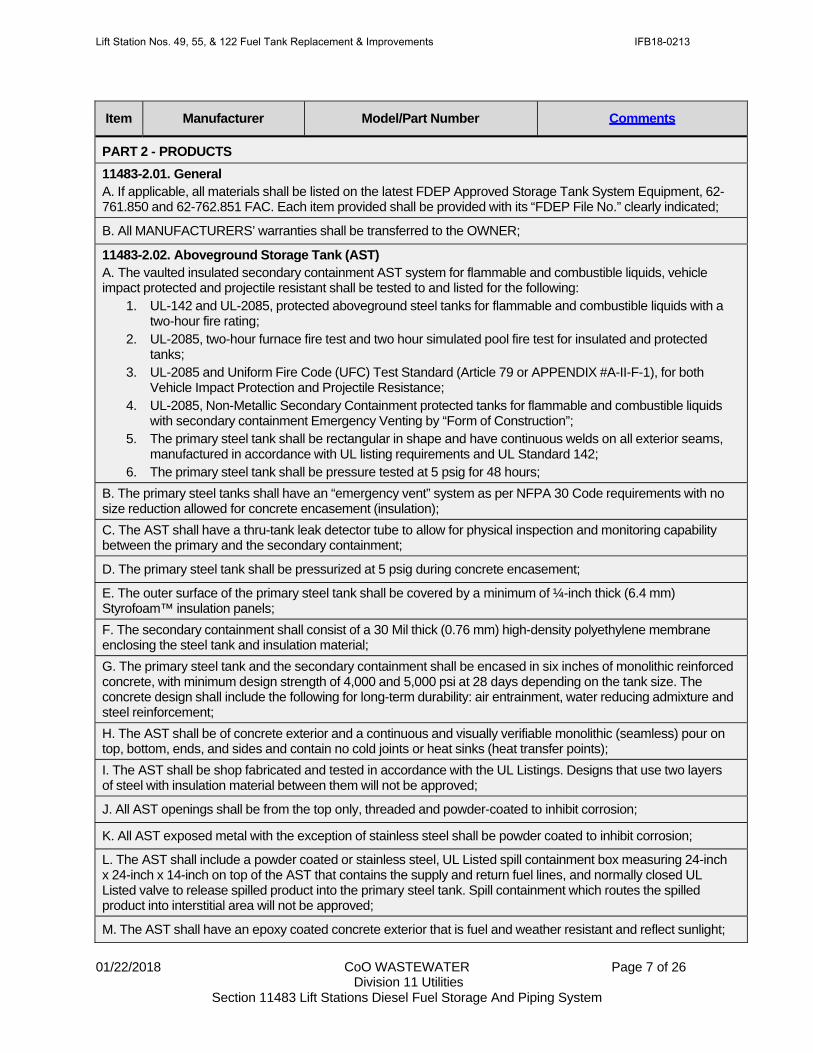
11483-2.01. General A. If applicable, all materials shall be listed on the latest FDEP Approved Storage Tank System Equipment, 62- 761.850 and 62-762.851 FAC. Each item provided shall be provided with its “FDEP File No.” clearly indicated;
B. All MANUFACTURERS’ warranties shall be transferred to the OWNER;
11483-2.02. Aboveground Storage Tank (AST) A. The vaulted insulated secondary containment AST system for flammable and combustible liquids, vehicle impact protected and projectile resistant shall be tested to and listed for the following:
1. UL-142 and UL-2085, protected aboveground steel tanks for flammable and combustible liquids with a two-hour fire rating;
2. UL-2085, two-hour furnace fire test and two hour simulated pool fire test for insulated and protected tanks;
3. UL-2085 and Uniform Fire Code (UFC) Test Standard (Article 79 or APPENDIX #A-II-F-1), for both Vehicle Impact Protection and Projectile Resistance;
4. UL-2085, Non-Metallic Secondary Containment protected tanks for flammable and combustible liquids with secondary containment Emergency Venting by “Form of Construction”;
5. The primary steel tank shall be rectangular in shape and have continuous welds on all exterior seams, manufactured in accordance with UL listing requirements and UL Standard 142;
6. The primary steel tank shall be pressure tested at 5 psig for 48 hours;
B. The primary steel tanks shall have an “emergency vent” system as per NFPA 30 Code requirements with no size reduction allowed for concrete encasement (insulation);
C. The AST shall have a thru-tank leak detector tube to allow for physical inspection and monitoring capability between the primary and the secondary containment;
D. The primary steel tank shall be pressurized at 5 psig during concrete encasement;
E. The outer surface of the primary steel tank shall be covered by a minimum of ¼-inch thick (6.4 mm) Styrofoam™ insulation panels;
F. The secondary containment shall consist of a 30 Mil thick (0.76 mm) high-density polyethylene membrane enclosing the steel tank and insulation material;
G. The primary steel tank and the secondary containment shall be encased in six inches of monolithic reinforced concrete, with minimum design strength of 4,000 and 5,000 psi at 28 days depending on the tank size. The concrete design shall include the following for long-term durability: air entrainment, water reducing admixture and steel reinforcement;
H. The AST shall be of concrete exterior and a continuous and visually verifiable monolithic (seamless) pour on top, bottom, ends, and sides and contain no cold joints or heat sinks (heat transfer points);
I. The AST shall be shop fabricated and tested in accordance with the UL Listings. Designs that use two layers of steel with insulation material between them will not be approved;
J. All AST openings shall be from the top only, threaded and powder-coated to inhibit corrosion;
K. All AST exposed metal with the exception of stainless steel shall be powder coated to inhibit corrosion;
L. The AST shall include a powder coated or stainless steel, UL Listed spill containment box measuring 24-inch x 24-inch x 14-inch on top of the AST that contains the supply and return fuel lines, and normally closed UL Listed valve to release spilled product into the primary steel tank. Spill containment which routes the spilled product into interstitial area will not be approved;
M. The AST shall have an epoxy coated concrete exterior that is fuel and weather resistant and reflect sunlight;
Lift Station Nos. 49, 55, & 122 Fuel Tank Replacement & Improvements IFB18-0213

01/22/2018 CoO WASTEWATER Division 11 Utilities
Section 11483 Lift Stations Diesel Fuel Storage And Piping System
Page 8 of 26
Item Manufacturer Model/Part Number Comments
N. The AST shall have side mounted galvanized steel stairs with rails for filling and servicing purposes. The stairs shall be manufactured by the same MANUFACTURER providing the AST;
O. The AST shall have a warranty of 30 years. The AST design shall have been in use for a minimum of twenty (20) years;
P. The AST shall have two (2) bolts for connecting grounding conductors for lightning protection in accordance with NFPA 780;
Q. The AST shall have a hurricane hold down restraint system and be placed on a neoprene bearing pad on a reinforced concrete pad made to MANUFACTURER’s specifications, properly engineered for the weight and conditions;
R. The AST shall have appropriate warning signs (i.e. FLAMMABLE, NO SMOKING, DIESEL, etc.) as required by the local jurisdiction;
S. The AST shall have the total gross capacity in gallons clearly visible;
T. The AST shall have signage on top indicating proper filling procedure and a tank calibration chart;
U. All ASTs provided under this project shall be of the same MANUFACTURER and model;
V. All ASTs shall be rectangular as shown on the Drawings;
W. All ASTs shall include the specified AST Accessories as listed in 11483-2.03; 1. Fill Limiter-Shutoff Valve; 2. 1-inch Double Poppet Foot Valve; 3. A mechanical level gauge shall be provided to indicate the liquid level within the tank;
D. Acceptable AST MANUFACTURERs;
1.
CONVAULT® OF FLORIDA www.convault.com
Model CVT;
FDEP File No. EQ-419;
$20k for 2k; $25k for 3k; $28k for 4k;
2.
DEL ZOTTO PRODUCTS OF FLORIDA, INC. www.armorfueltank.com www.delzottoproducts.co m
Armor Cast AST;
FDEP File No. EQ-754;
11483-2.03. AST Accessories A. The tank shall include all openings required for fueling, venting, level monitoring and leak monitoring as required by these Specifications & Drawings;
B. The following equipment shall be furnished along with the necessary piping and fittings required to provide a complete diesel fuel storage & piping system:
1. Vent piping shall be twelve feet above and be provided as specified in Section 11483-2.04; 2. An emergency vent shall be provided for the tank of the size required by code as specified in Section
Lift Station Nos. 49, 55, & 122 Fuel Tank Replacement & Improvements IFB18-0213

01/22/2018 CoO WASTEWATER Division 11 Utilities
Section 11483 Lift Stations Diesel Fuel Storage And Piping System
Page 9 of 26
Item Manufacturer Model/Part Number Comments
11483-2.05; 3. Isolation and ball valves shall be sized appropriately with bronze bodies, Teflon seals, lockable handles
and stainless steel trim as specified in Section 11483-2.06; 4. An anti-siphon valve shall be installed on the supply line as specified in Section 11483-2.07; 5. Overfill protection stop valve shall be installed on the tank as specified in Section 11483-2.08; 6. A double poppet foot valve shall be installed inside the AST at the fuel intake line four (4) inches above
the bottom of the tank to hold prime as specified in Section 11483-2.09; 7. An external AST emergency shutoff valve shall be installed in the fuel supply line at the day tank
specified in Section 11483-2.10; 8. Provide all piping, valves, unions, filters, strainers and other accessories as required for a complete
system.
11483-2.04. AST Accessories, Vent Cap A. Vent piping shall be two-inches and shall be provided with a vent cap constructed of aluminum with removable stainless steel screen;
B. Acceptable AST Accessories, Vent Cap MANUFACTURERs;
1.
MORRISON BROS. CO. www.morbros.com
Figure 354 Series;
Open Atmospheric Vent;
2.
OPW®, A Dover™ Company www.opwglobal.com
Model 23 Series;
Open Atmospheric Vent;
11483-2.05. AST Accessories, Emergency Vent A. The emergency vent shall be constructed of an epoxy coated cast iron lid, aluminum body and a removable stainless steel screen;
B. Acceptable AST Accessories, Emergency Vent MANUFACTURERs;
1.
MORRISON BROS. CO. www.morbros.com
Figure 244 Series;
2. OPW®, A Dover™ Company www.opwglobal.com
Model 201 Series;
11483-2.06. AST Accessories, Isolation and Ball Valves A. Isolation and ball valves shall be sized appropriately with bronze bodies, Teflon seals, lockable handles and stainless steel trim;
B. Acceptable AST Accessories, Isolation and Ball Valves MANUFACTURERs;
1.
MORRISON BROS. CO. www.morbros.com
Figure 691B Full Port Two-Way Ball Valve Series with Lockable Handles;
Lift Station Nos. 49, 55, & 122 Fuel Tank Replacement & Improvements IFB18-0213

01/22/2018 CoO WASTEWATER Division 11 Utilities
Section 11483 Lift Stations Diesel Fuel Storage And Piping System
Page 10 of 26
Item Manufacturer Model/Part Number Comments
2.
OPW®, A Dover™ Company www.opwglobal.com
Model 21BV-0900LH Full Port Two- Way Ball Valve Series with Lockable Handles; where: 9=1 for 1"; 2 for 2"; 3 for 3";
11483-2.07. AST Accessories, Anti-Siphon Valve A. An anti-siphon valve shall be installed to help prevent siphoning of an AST should a leak or break occur in the fuel supply line;
B. Acceptable AST Accessories, Anti-Siphon Valve MANUFACTURERs;
1.
MORRISON BROS. CO. www.morbros.com
Figure 912 Series;
2.
OPW®, A Dover™ Company www.opwglobal.com
Model 199ASV Anti-Siphon Valve;
11483-2.08. AST Accessories, Overfill Protection Stop Valve A. Overfill protection stop valve shall be installed on the tank and be capable of stopping diesel fuel flow at 90- 95% capacity;
B. Acceptable AST Accessories, Overfill Protection Stop Valve MANUFACTURERs;
1.
MORRISON BROS. CO. www.morbros.com
Figure 9095A Series;
FDEP File No. EQ-356
2.
OPW®, A Dover™ Company www.opwglobal.com
Model 61FSTOP-2000 Series;
FDEP File No. EQ-225;
11483-2.09. AST Accessories, Double Poppet Foot Valve A. A double poppet foot valve shall be installed inside the aboveground tank at the fuel intake line 6(8)-inches above the bottom of the tank to hold prime;
B. Acceptable AST Accessories, Double Poppet Foot Valve MANUFACTURERs;
1.
MORRISON BROS. CO. www.morbros.com
Figure 335A Series;
Lift Station Nos. 49, 55, & 122 Fuel Tank Replacement & Improvements IFB18-0213

01/22/2018 CoO WASTEWATER Division 11 Utilities
Section 11483 Lift Stations Diesel Fuel Storage And Piping System
Page 11 of 26
Item Manufacturer Model/Part Number Comments
2.
OPW®, A Dover™ Company www.opwglobal.com
Model 92 Series;
11483-2.10. AST Accessories, External AST Emergency Shutoff Valve A. An external AST emergency shutoff valve shall be installed in the fuel supply line at the day tank; Often referred to as a "Fire Valve." Used to shut off flow in the event of fire. Fuse link holds open spring actuated lever. Mounts on external pipeline;
B. Acceptable AST Accessories, External AST Emergency Shutoff Valve MANUFACTURERs;
1.
MORRISON BROS. CO. www.morbros.com
Figure 346 Series;
2.
OPW®, A Dover™ Company www.opwglobal.com
Model 178S-6130;
11483-2.11. Pipe and Fittings A. Exterior aboveground and underground primary piping shall be Schedule 40 Type 316 Stainless Steel in conformance with ASTM Standards with 125 pound butt-welded stainless steel fittings conforming to ASTM Standards.
C. Terminating fittings to product pipe shall be the MANUFACTURER's standard fittings applied as recommended by the MANUFACTURER. The termination fittings shall be rated to 5 psi test pressure;
D. Concentric spacers shall be supplied in accordance with the MANUFACTURER’s spacing requirements;
E. Long sweep elbows shall be used for all changes in direction at the containment piping;
F. Provide seals at building wall and transition sump to seal between the pipes within the containment piping and the inside of the containment piping;
G. Provide a pressure test port with threaded plug for each individual segment of double wall fuel lines;
H. Piping transition sumps shall be suitable pressure testing and visual leak detection of all containment piping.
11483-2.12. Pipe and Fittings, Exterior Primary Piping, Fittings and Connections A. Exterior (aboveground and underground) primary piping shall be Schedule 40 Type 316 Stainless Steel in conformance with ASTM Standards with 125 pound butt-welded stainless steel fittings conforming to ASTM Standards.
B. Acceptable Pipe and Fittings, Exterior Primary Piping, Fittings and Connections MANUFACTURERs;
1.
TAYLOR FORGE STAINLESS, INC. www.taylorforgestainless. com
Schedule 40 Type 316 Stainless Steel Pipe, Fittings & Connections;
2.
FELKER BROS. CORP. www.felkerbrothers.com
Schedule 40 Type 316 Stainless Steel Pipe, Fittings & Connections;
Lift Station Nos. 49, 55, & 122 Fuel Tank Replacement & Improvements IFB18-0213

01/22/2018 CoO WASTEWATER Division 11 Utilities
Section 11483 Lift Stations Diesel Fuel Storage And Piping System
Page 12 of 26
Item Manufacturer Model/Part Number Comments
3. OWNER Preapproved Equal
11483-2.13. Pipe and Fittings, Fiberglass Reinforced Plastic (FRP) Secondary Containment Piping, Fittings and Connections A. Exterior (aboveground and underground) primary piping shall be contained in fiberglass reinforced plastic (FRP) secondary containment piping in conformance with ASTM Standards with FRP fittings and connections conforming to ASTM Standards.
B. All aboveground fiberglass secondary containment piping shall be painted according to MANUFACTURER’s recommendation with a good epoxy-based paint to prevent UV radiation damage;
C. Acceptable Pipe and Fittings, Fiberglass Reinforced Plastic (FRP) Secondary Containment Piping, Fittings and Connections MANUFACTURERs;
1.
AMERON INTERNATIONAL www.dualoy- fuelhandling.com
Dualoy® 3000/L Pipe System
Fiberglass-Composite Pipe Group FDEP File No. EQ-378;
2.
SMITH FIBERGLASS PRODUCTS, INC. www.smithfibercast.com
SMITH FIBERCAST Red Thread® IIA Piping System
FDEP File No. EQ-252;
11483-2.14. Pipe and Fittings, Interior Aboveground Fuel, Vent Piping and Fittings A. Interior aboveground fuel, vent piping and fittings shall be Schedule 40 black iron (a.k.a. fire sprinkler pipe) in conformance with ASTM-795 and ANSI B31.3-1980 with 125-pound threaded malleable iron fittings conforming to ANSI B16.3 and ANSI B31.3-1980;
B. Acceptable Pipe and Fittings, Interior Aboveground Fuel, Vent Piping and Fittings MANUFACTURERs;
1.
WHEATLAND TUBE www.wheatland.com
Schedule 40 Sprinkler Pipe
2.
ALLIED TUBE & CONDUIT www.alliedtube-sprinkler.com
Schedule 40 ABFII Sprinkler Pipe
3. OWNER Preapproved Equal
11483-2.15. Pipe and Fittings, Exterior Flexible Piping at Tank, Containment Sumps and Equipment Connections A. Exterior flexible piping at tank, containment sumps and equipment connections shall be all metal construction of corrosion resistant stainless steel connectors; UL 2039 Listed;
B. Acceptable Pipe and Fittings, Exterior Flexible Piping at Tank, Containment Sumps and Equipment Connections MANUFACTURERs;
1.
FLEX-ING, INC. www.flex-ing.com
Fireflex Connectors with 346 Swivel Connectors
Lift Station Nos. 49, 55, & 122 Fuel Tank Replacement & Improvements IFB18-0213

01/22/2018 CoO WASTEWATER Division 11 Utilities
Section 11483 Lift Stations Diesel Fuel Storage And Piping System
Page 13 of 26
Item Manufacturer Model/Part Number Comments
2.
OPW®, A Dover™ Company www.opwglobal.com
Stainless Steel Flexible Connectors
11483-2.16. Pipe and Fittings, Interior Flexible Piping at Tank, Containment Sumps and Equipment Connections A. Interior flexible piping at tank, containment sumps and equipment connections shall be seamless flexible plastic liner with corrosion resistant stainless steel wire braid reinforced cover and S80 Hex fittings connectors; UL 2039 Listed;
B. Acceptable Pipe and Fittings, Interior Flexible Piping at Tank, Containment Sumps and Equipment Connections MANUFACTURERs;
1.
HOSE MASTER, INC. www.hosemaster.com
Fire-Shield Connectors
2. OWNER Preapproved Equal
11483-2.17. Pipe and Fittings, Piping Transitions, Sleeves and Supports A. Provide piping transitions, sleeves and supports as required for a rigid support and complete installation. All fuel pipe building wall penetrations shall be watertight.
B. Acceptable Pipe and Fittings, Piping Transitions, Sleeves and Supports MANUFACTURERs;
1.
EGS ELECTRICAL GROUP www.o-zgedney.com
O-Z/GEDNEY ThruWall and Floor Seals, Type WSK;
2. OWNER Preapproved Equal
11483-2.18. Pipe and Fittings, Hangers and Straps A. Hangers shall be Type 316 stainless steel;
B. One-hole and two-hole straps shall be Type 316 stainless steel with "Clamp Backs";
B. Acceptable Pipe and Fittings, Hanger and Strap MANUFACTURERs;
1.
EGS ELECTRICAL GROUP www.egseg.com www.o-zgedney.com
O-Z/GEDNEY Brand;
2.
THOMAS AND BETTS CO. www.tnb.com
STEEL CITY® Brand; KINDORF® Brand; or SUPERSTRUT® Brand;
3. OWNER Preapproved Equal
11483-2.19. Pipe and Fittings, Support & Framing Channels and Fittings A. Channels for Dry, Wet and Corrosive Areas shall be Type 316 stainless steel;
B. Fittings shall be Type 316 stainless steel;
Lift Station Nos. 49, 55, & 122 Fuel Tank Replacement & Improvements IFB18-0213

01/22/2018 CoO WASTEWATER Division 11 Utilities
Section 11483 Lift Stations Diesel Fuel Storage And Piping System
Page 14 of 26
Item Manufacturer Model/Part Number Comments
C. All installations shall include protective end caps;
D. Acceptable Pipe and Fittings, Support & Framing Channel and Fitting MANUFACTURERs
1.
COOPER B-LINE® www.cooperbline.com
Strut Systems & Bolted Framing Products;
2.
THOMAS AND BETTS CO. www.tnb.com
KINDORF® Brand; or SUPERSTRUT® Brand;
3. ATKORE INTERNATIONAL www.unistrut.com
UNISTRUT® CORP. Products;
4. OWNER Preapproved Equal
11483-2.20. Pipe and Fittings, Anchors A. Mechanical anchoring systems shall be Type 316 stainless steel self-drilling and expansion bolt types;
B. Acceptable Pipe and Fittings, Anchor MANUFACTURERs
1.
ITW RED HEAD (formerly (ITT) PHILLIPS DRILL CO.) www.itw-redhead.com
RED HEAD® Products;
2.
POWERS FASTENERS INC. (formerly RAWL PRODUCTS CO.) www.powers.com
POWERS Products;
3. OWNER Preapproved Equal
11483-2.21. Pipe and Fittings, Miscellaneous Hardware A. All Hardware shall be Type 316 stainless steel including screws, nuts, bolts, washers, etc.;
B. Acceptable Pipe and Fittings, Miscellaneous Hardware MANUFACTURERs
1. OWNER Approved
11483-2.22. Pipe and Fittings, Thread Sealant A. Thread sealant for steel (and stainless steel) pipe threaded connections shall be a non-hardening, non- solvent joint sealer and compatible for diesel and bio-diesel applications
B. Acceptable Pipe and Fittings, Thread Sealant MANUFACTURERs;
1.
HENKEL CORPORATION www.henkelna.com
LOCTITE® Low Halogen/Low Sulfur PST® 580™ Thread Sealant
Lift Station Nos. 49, 55, & 122 Fuel Tank Replacement & Improvements IFB18-0213

01/22/2018 CoO WASTEWATER Division 11 Utilities
Section 11483 Lift Stations Diesel Fuel Storage And Piping System
Page 15 of 26
Item Manufacturer Model/Part Number Comments
2. OWNER Preapproved Equal
11483-2.23. Instrumentation & Leak Monitoring A. Furnish a direct reading gauge for visible level monitoring properly installed on the AST;
B. Furnish a magnetostrictive level/temperature transmitter properly installed on the AST for future telemetry integration;
C. Furnish a tank monitoring system including tank alarm console, high level detection, low level detection, double containment tank leak sensing, and secondary containment piping leak detection and associated modules for a complete tank leak detection system;
D. The tank monitoring system shall include provisions for remote monitoring of alarm conditions.
E. The tank monitoring system shall include an integral and remote mounted audible electronic horn and flashing red light to indicate a trouble or leak condition.
F. The tank monitoring system includes all required terminals, switches, transmitters and local wiring shall be complete. Wiring required between sensors and panels shall be furnished. All wiring shall be installed in conduits per NEC and approved for location.
G. The tank monitoring system console shall be labeled correctly & properly for HIGH LEVEL ALARM, LOW LEVEL ALARM, TANK LEAK ALARM, PIPE LEAK ALARM, RESET, HIGH WATER LEVEL ALARM and TEST
H. The tank monitoring system shall meet all applicable regulatory requirements for tank leak detection, monitoring and reporting.
I. One complete system shall be provided for each new AST.
J. The monitoring system shall be mounted on a stainless steel UNISTRUT® frame at location approved by ENGINEER and OWNER. Secure to frame using stainless steel fasteners. Coordinate mounting location with field conditions.
K. The system and associated sensors shall be as specified in Section 11483-26;
L. Tank level detection – Tank high/low level floats and secondary piping containment sensors shall be custom length PNEUMERCATOR™ CO., INC. Model LS-600 Series (FDEP File No. EQ-240) or City Preapproved Equal. The floats and sensors shall be furnished complete with the installation kits, riser caps, seals and other parts as required for a complete installation.
M. Double Wall Interstitial Leak Sensor – The double wall interstitial leak sensor shall be capable of detecting the presence of any liquid in the annulus of the AST. The sensor shall be a PNEUMERCATOR™ CO., INC. Model LS-600-LDSS or City Preapproved Equal. The 316 Stainless Steel Float, Shaft with Teflon® wiring sensor shall be furnished complete with the installation kits, riser caps, seals and other parts as required for a complete installation.
N. Spill Kit – A 30 gallon spill kit shall be provided for each new AST.
11483-2.24. Instrumentation & Leak Monitoring, Visible Level Monitoring A. Features:
1. Top mounted liquid level gauge that can measure from 6-inches to 120-inches in depth; 2. Stainless steel rods or chain and float;
B. Acceptable Instrumentation & Leak Monitoring, Visible Level Monitoring MANUFACTURERs;
1.
KRUEGER SENTRY GAUGE www.kruegersentrygauge .com
Therma Gauge Stainless Liquid Level Tank Gauge Type H-AllSS; Catalog No. H-(size opening)-(tank depth)+(ext)-(AllSS) Sample—H-2-48+12 –AllSS;
Lift Stations Standard; FDEP File No. EQ-730;
Lift Station Nos. 49, 55, & 122 Fuel Tank Replacement & Improvements IFB18-0213

01/22/2018 CoO WASTEWATER Division 11 Utilities
Section 11483 Lift Stations Diesel Fuel Storage And Piping System
Page 16 of 26
Item Manufacturer Model/Part Number Comments
Custom order - 6 inches to 12 feet in depth;
2.
MORRISON BROS. CO. www.morbros.com
Figure 818 Stainless Steel Float & Cable Clock Gauge
C1, C2 & IB Standard; FDEP File No. EQ-227;
11483-2.25. Instrumentation & Leak Monitoring, Magnetostrictive Level Sensor A. Magnetostrictive level sensors are similar to float type sensors in that a permanent magnet sealed inside a float travels up and down a stem in which a magnetostrictive wire is sealed. Ideal for high-accuracy, continuous level measurement of a wide variety of liquids in storage and shipping containers, these sensors require the proper choice of float based on the specific gravity of the liquid. When choosing float and stem materials for magnetostrictive level sensors, the same guidelines described for magnetic and mechanical float level sensors apply.
B. Because of the degree of accuracy possible with the magnetostrictive technique, it is popular for “custody- transfer” applications. It can be permitted by an agency of weights and measures for conducting commercial transactions. It is also frequently applied on magnetic sight gages. In this variation, the magnet is installed in a float that travels inside a gage glass or tube. The magnet operates on the sensor which is mounted externally on the gauge.
C. Acceptable Instrumentation & Leak Monitoring, Magnetostrictive Level Sensor MANUFACTURERs
1.
K-TEK, A MEMBER OF THE ABB GROUP www.ktekcorp.com
ACCUTRAK™ AT100 High Accuracy Magnetostrictive Level Transmitter; Part No. AT100/S6/LW/A/R1/H0/M4A/X/FM/CF/ F27T-2/999.99-inch, where AT100 = mounted in the process; S6 = 316 stainless steel probe; LW = local integral electronics with windowed cover and LCD display; A = aluminum dual compartment housing; R1 = standard 5/8-inch o.d. RIGID probe; H0 = 170 °F (77 °C) max; M4A = 2-wire loop-powered 4 - 20mA
Typical – Rigid pipe, 4-20mA output, level1 (diesel)
Lift Station Nos. 49, 55, & 122 Fuel Tank Replacement & Improvements IFB18-0213

01/22/2018 CoO WASTEWATER Division 11 Utilities
Section 11483 Lift Stations Diesel Fuel Storage And Piping System
Page 17 of 26
Item Manufacturer Model/Part Number Comments
output; X = no option; FM = Factory Mutual approval, NEMA 4/4X/7/9/XP; CF = ¾-inch MNPT adjustable compression fitting; F27T-2 = 1.88-inch o.d. x 4.21-inch long float, 0.65 Sp. Gr. minimum; 999.99” = inches of probe length;
2.
MTS® SYSTEMS CORPORATION SENSORS DIVISION www.mtssensors.com
Level Plus® M-Series Analog (MR) FLEX Liquid Level Sensor; Part No. 01-06 550904 Rev. C, Model No. MRA1A1B11A0U99999S, where M = Magnetostrictive transmitter; R = Analog output liquid-level; A = 24VDC, 2-wire loop input power; 1 = 4-20mA Single loop output; A = NEMA Type 4X, 316L Stainless Steel with cable (intrinsically safe only) housing; 1 = Integral electronics mounting; B = Industrial end-plug with stop collar transmitter pipe; 1 = 316L SS wetted parts; 1 = NPT adjustable fitting process connection type; A = ¾-inch (NPT for 5/8-inch pipe process connection size; 0 = No temperature sensors; U = US customary (inches) 99999 = Length in inches 999.99 (20.00-inch to 300.00-inch); S = Standard product;
Typical – Rigid pipe, 4-20mA output, level1 (diesel)
Standard product float for diesel, 0.65 Specific Gravity, Part No. 251981-1;
11483-2.26. Instrumentation & Leak Monitoring, Tank Monitoring System A. Features:
1. NEMA 4 Weatherproof water tight wall mount enclosure; 2. High and low level warning lights; 3. Test pushbutton; 4. Audible (85dB) alarm with reset button; 5. Intrinsically safe operation of tank and secondary containment mounted sensors; 6. Alarm Console Power - 120VAC, 60Hz; 7. (3) Field Sensor Inputs – 12VDC at 15mA; 8. (3) Relay Outputs – SPDT per point, rated 3A at 120VAC; selectable NO or NC;
Lift Station Nos. 49, 55, & 122 Fuel Tank Replacement & Improvements IFB18-0213

01/22/2018 CoO WASTEWATER Division 11 Utilities
Section 11483 Lift Stations Diesel Fuel Storage And Piping System
Page 18 of 26
Item Manufacturer Model/Part Number Comments
9. Environmental - -40 to 160 °F (-40 to 71 °C);
B. Acceptable Instrumentation & Leak Monitoring, Tank Monitoring System MANUFACTURERs;
1.
PNEUMERCATOR™ CO. www.pneumercator.com
Model LC1004 Tank Monitoring System;
FDEP File No. EQ-319;
2.
RONAN www.ronan.com
Series X76AST-4X;
FDEP File No. EQ-059;
11483-2.27. Instrumentation & Leak Monitoring, Tank Level Detection Sensors A. Features:
1. Magnetic switch float(s); 2. Stainless Steel construction; 3. NO or NC selectable switch; 4. UL Listed & FM Approved;
B. Acceptable Instrumentation & Leak Monitoring, Tank Level Detection Sensors MANUFACTURERs;
1.
PNEUMERCATOR™ CO. www.pneumercator.com
Model LS-600 Series;
FDEP File No. EQ-240;
2.
RONAN www.ronan.com
Discriminating Sensor Model LS-3SS;
FDEP File No. EQ-263;
11483-2.28. Instrumentation & Leak Monitoring, Double Wall Interstitial Leak Sensor A. Features:
1. Magnetic switch float(s); 2. Stainless Steel construction; 3. NO or NC selectable switch;
UL Listed & FM Approved;
Lift Station Nos. 49, 55, & 122 Fuel Tank Replacement & Improvements IFB18-0213

01/22/2018 CoO WASTEWATER Division 11 Utilities
Section 11483 Lift Stations Diesel Fuel Storage And Piping System
Page 19 of 26
Item Manufacturer Model/Part Number Comments
B. Acceptable Instrumentation & Leak Monitoring, Double Wall Interstitial Leak Sensor MANUFACTURERs;
1.
PNEUMERCATOR™ CO. www.pneumercator.com
Model LS-600-LDSS;
FDEP File No. EQ-240;
2.
RONAN www.ronan.com
Discriminating Sensor Model LS-3SS;
FDEP File No. EQ-263;
11483-2.29. Diesel Fuel Day Tank A. If a day tank is needed, the CONTRACTOR shall furnish and install a day tank for the emergency lift station generator. A 50-gallon day tank shall be provided for those lift stations with a 1,000-gallon or less AST. A 100- gallon day tank shall be provided for those lift stations with an AST larger than 1,000-gallon.
B. Day tank shall be constructed in accordance with 1. UL-142 Standard - Steel Aboveground Tanks for Flammable and Combustible Liquids; 2. NFPA 30 - Flammable and Combustible Liquids Code; and 3. NFPA 37 - The Standard for Installation and use of Stationary Combustible Engine and Gas Turbines;
C. Day tank shall be made of heavy gauge steel construction;
D. Day tank shall be coated with rust inhibitor inside, primed and finish painted outside;
E. Required day tank connections include: 1. Tank supply; 2. Generator supply; 3. Generator return; 4. Normal vent; 5. Emergency vent; 6. Tank overflow; 7. Inspection port and manual fill cap; 8. Tank drain;
F. The tank shall be provided with atmospheric (normal) vent cap with screen and appropriately sized UL Listed emergency vent cap. UL Listed emergency vent cap shall be pressure operated. Opening pressure shall be 0.5 psig; full opening pressure 2.5 psig. Limits shall be marked on top of each vent.
G. The day tank shall include a welded steel double wall containment basin to prevent escape of fuel into the environment in the event of a tank rupture. The secondary containment basin shall consist of a welded heavy gauge steel structure sized at a minimum of 150% of the tank capacity. The exterior of the basin shall be primed
Lift Station Nos. 49, 55, & 122 Fuel Tank Replacement & Improvements IFB18-0213

01/22/2018 CoO WASTEWATER Division 11 Utilities
Section 11483 Lift Stations Diesel Fuel Storage And Piping System
Page 20 of 26
Item Manufacturer Model/Part Number Comments
and finish painted. The basin shall include a welded steel top with an appropriately sized NPT fitting for emergency vent, and appropriately sized zinc-plated emergency vent cap. Emergency vent cap shall be spring pressure operated. Opening pressure shall be 0.5 psig; full opening pressure 2.5 psig. Limits shall be marked on top of each vent.
H. A rupture basin leak detector switch shall be wired into the day tank’s electronic level controller. This switch shall shut down the supply pump and motor in case of a fuel leak into the double wall containment basin.
I. The tank shall include a direct-reading fuel level gauge;
J. The electronic level controller shall have the following as part of the system: 1. Fuel level indicator; 2. High fuel level warning; 3. Low fuel level warning; 4. Critical low level shut off; 5. Fuel in basin alarm; 6. Supply & Return Pump control; 7. High water condition in day tank alarm; 8. Electronic level controller functional signal; 9. All warnings shall provide contacts for remote annunciation; 10. All signals and warnings shall be indicated by LED lights; 11. All warnings shall be provided with normally open (NO) and normally closed (NC) contacts for remote
annunciation; 12. Pump manually control with “On”, “Off” and “Test” buttons; 13. UL-508 listed; 14. Electrical characteristics shall be 120VAC, 1 phase, 60 Hz;
K. The tank shall include a heavy-duty, self-priming, positive displacement rotary gear pump with corrosion- resistant bronze housing and gears with stainless steel shafts, self lubricating carbon bearings with lip seals diesel fuel supply pump (minimum two gallons per minute) and motor to draw diesel fuel from the AST to the day tank. Pump shall be mounted directed to motor via carbonator style split tang coupling. Pump capacity shall be sized as appropriate, and provide a minimum of 15-feet of vertical lift at sea level. A minimum 1/3 HP, open drip-proof (squirrel cage), single phase, auto-thermal protected, bearing supported shaft, Class B insulation for continuous 40 °C operation motor shall be provided of sufficient horsepower to operate the pump. Motor electrical characteristics shall be 120VAC, 1 phase, 60 Hertz, thermally protected.
L. The supply fuel line shall have a solenoid valve, 1-inch NPT, 100PSI, normally closed installed on the supply fuel inlet to prevent tank flooding.
M. The supply fuel line shall have an in-line check valve installed to ensure that the pump does not have to evacuate a large volume of air during each operation and keep line from the AST “primed”.
N. An inline fuel/water separator shall be installed on the inlet side of the diesel fuel supply pump.
O. The tank shall include a heavy-duty, self-priming, positive displacement rotary gear pump with corrosion- resistant bronze housing and gears with stainless steel shafts, self lubricating carbon bearings with lip seals diesel fuel return pump (minimum two gallons per minute) and motor to return fuel to the AST in the event the day tank level exceeds 110% of its normal capacity or maintenance. A minimum 1/3 HP, open drip-proof (squirrel cage), single phase, auto-thermal protected, bearing supported shaft, Class B insulation for continuous 40 °C operation motor shall be provided of sufficient horsepower to operate the pump. The return pump/motor shall be activated by a separate, critical high level float switch or manually controlled. Motor electrical characteristics shall be 120VAC, 1 phase, 60 Hertz, thermally protected. The return pump/motor capacity shall be equal to or greater than the capacity of the supply pump.
P. The return fuel line shall have a shut-off ball valve and in-line check valve installed to prevent back-flow from return line to AST.
Lift Station Nos. 49, 55, & 122 Fuel Tank Replacement & Improvements IFB18-0213

01/22/2018 CoO WASTEWATER Division 11 Utilities
Section 11483 Lift Stations Diesel Fuel Storage And Piping System
Page 21 of 26
Item Manufacturer Model/Part Number Comments
Q. A side-mounted ten (10) gallons per minute, 50 stroke, piston-type, hand pump with in-line check valve shall be installed for initial priming to avoid undue wear on the diesel fuel supply pump.
R. Day tank MANUFACTURER shall have a minimum of ten years’ experience in the design and construction of UL Listed day tank systems.
S. Day tank MANUFACTURER shall be UL listed;
T. Acceptable Diesel Fuel Day Tank MANUFACTURERs;
1.
ENGINE & COMPRESSOR ACCESSORIES (E&CA) www.daytank.com
Secondary Containment Automatic Series
2.
SIMPLEX, INC. www.simplexdirect.com
SIMPLX® SST Series
3.
TRAMONT™ CORPORATION www.tramont.com
TRS Series
50-gal $5,100 each; 100-gal $7,500 each;
11483-2.30. Diesel Fuel Day Tank (Generator) Supply Line Fuel/Water Separator A. Provide an inline fuel/water separator on the fuel supply line of the day tank;
B. Acceptable Diesel Fuel Day Tank (Generator) Supply Line Fuel/Water Separator MANUFACTURERs;
1.
BALDWIN FILTERS® www.baldwinfilter.com
DAHL Model 300 Series;
2. PARKER HANNIFIN CORP. www.parker.com/racor
RACOR® Turbine Model 1000FH Series
3. OWNER Preapproved Equal
11483-2.31. Diesel Fuel Day Tank (Generator) Fuel Supply Line Solenoid Valve A. A solenoid valve shall be installed in the fuel intake line;
B. Acceptable Diesel Fuel Day Tank (Generator) Fuel Supply Line Solenoid Valve MANUFACTURERs;
Lift Station Nos. 49, 55, & 122 Fuel Tank Replacement & Improvements IFB18-0213

01/22/2018 CoO WASTEWATER Division 11 Utilities
Section 11483 Lift Stations Diesel Fuel Storage And Piping System
Page 22 of 26
Item Manufacturer Model/Part Number Comments
1.
MORRISON BROS. CO. www.morbros.com
Figure 710 Series;
2.
OPW®, A Dover™ Company www.opw-fc.com
Model 821-0900AC; where: 9 = 1 for 1"; 2 for 2"; 3 for 3";
11483-2.32. Painting, Coatings and Labeling A. Conform to ANSI / ASME A13.1; Diesel fuel pipe markers, black text on yellow, shall be placed: • To indicate direction of flow by labeling with arrows at one or both ends; • To be visible from the point of normal approach; • At any line entry or re-entry point; • Near valves, flanges and changes in pipe direction; • At both sides of ceiling, wall or floor penetrations; • At least once every 50-feet on straight pipe runs;
B. Acceptable Painting, Coatings and Labeling MANUFACTURERs;
1.
KLASS KOTE www.klasskote.com
Epoxy (Color - Yellow #160);
Apply to FRP Secondary Containment Piping, Fittings And Connections;
2. OWNER Preapproved Equal
Lift Station Nos. 49, 55, & 122 Fuel Tank Replacement & Improvements IFB18-0213

01/22/2018 CoO WASTEWATER Division 11 Utilities
Section 11483 Lift Stations Diesel Fuel Storage And Piping System
Page 23 of 26
PART 3 – EXECUTION 11483-3.01. General A. Fuel storage & piping system installation are specialized skills. The CONTRACTOR shall have the knowledge; possess the skills and equipment necessary to install ASTs, piping, containment and day tanks properly and safely.
B. The elements of the fuel storage & piping system shall be supplied as an engineered solution by the CONTRACTOR. Each location fuel storage & piping system shall include all pumps, valves, level controls, pump controls and motor starters, indicators, alarms and all other devices as required to form an integrated, functional system such that field installation is restricted largely to piping, wiring and such intermediate devices that are required by code and/or good engineering practice to interconnect the AST to the day tank, the day tank to the emergency generator and to provide for external vents as per local codes and UL 142, NFPA 31 and NFPA 37.
C. All materials and equipment shall be new, free from defects or damage and shall be installed in accordance with the approved recommendations of the MANUFACTURER to conform to the specifications. The installation shall be accomplished by workmen skilled in this type of work. Equipment shall be erected in a neat manner, shall be aligned, leveled and adjusted to provide satisfactory operation. Install shall be such that connection and disconnection of piping and accessories can be readily made and so that all parts are easily accessible for inspection, operation, maintenance and repair. Minor deviations from indicated arrangements to provide proper access may be made.
D. Install all materials and equipment in accordance with the MANUFACTURER’s instructions and the Contract Drawings.
E. Remove temporary lifting angles, lugs, and shipping braces. Touch-up damaged paint finishes.
F. Caulk seams, cracks, and openings in outdoor enclosures.
11483-3.02. Installation of AST A. Permits And Approvals – The CONTRACTOR shall obtain all required permits and approvals prior to beginning any construction activities.
B. General - All components of fuel storage & piping system shall be installed in accordance with the MANUFACTURER’s instructions. Fuel storage tank systems shall be installed according to the applicable provisions of NFPA 30, NFPA 30A, STI R912 and PEI/RP200-03;
C. Damage - The OWNER will not tolerate any leakage from new installed tanks. No on-site repairs shall be allowed. A newly installed tank that leaks shall be replaced with another new tank, NO EXCEPTIONS.
D. Examination - Do not begin AST installation until substrates and adjacent construction have been properly constructed. Verify concrete tank pad, electrical service stub ups, bollard/barrier installation, clearances, setbacks, and other site related work that have impact to fueling system. If any unsatisfactory conditions are encountered, notify the OWNER at once. Do not proceed until unsatisfactory conditions have been corrected.
E. Tank Site – The approximate site of the new AST shall be approved by the ENGINEER & OWNER.
F. Foundation – The foundation for the tank must be designed to support the tank plus the weight of the maximum amount of product the tank will be storing. In addition:
1. The foundation design shall include provision for draining surface water away from the tank to minimize the risk of fuel accumulation under the tank from an overfill or spill;
2. Soil around foundation shall be sloped away 1/8-inch per foot minimum for 5-feet; 3. The foundation design shall incorporate provisions for hurricane hold down restraints; 4. The continuous solid monolith reinforced slab foundation is to sit on compacted fill, free of organic
material, which will uniformly distribute the weight of the tank and its contents to the soil: 2,000 lb. per sq. ft. bearing capacity; 1-inch maximum total settlement; ½-inch maximum differential settlement;
5. Provide a minimum six-inch (6") thick granular sub-grade, compacted and graded to a level uniform subsurface prior to pouring of the cast-in-place slab;
6. 95% compaction certified by third party report shall be provided BEFORE pad is poured or placed; 7. Bearing pads shall be used under the tank legs instead of grouting; the tank foundation and slab should
Lift Station Nos. 49, 55, & 122 Fuel Tank Replacement & Improvements IFB18-0213

01/22/2018 CoO WASTEWATER Division 11 Utilities
Section 11483 Lift Stations Diesel Fuel Storage And Piping System
Page 24 of 26
be designed to withstand concentrated loads under the bearing pads; 8. 2,000 Gallon Tanks or smaller may use the vaulted AST MANUFACTURER recommended pre-cast
slab;
G. Neoprene Bearing Pad - The AST neoprene bearing pad shall be installed in accordance with the MANUFACTURER’s instructions;
H. New Tank Handling – Unloading & Setting - The AST shall be handled in accordance with the MANUFACTURER’s instructions
I. Hurricane Hold down Restraint System – The AST Hurricane Hold down Restraint System shall be installed in accordance with the MANUFACTURER’s instructions per the Florida Building Code;
J. Electrical/Controls - Electrical service and fuel piping to the pumps shall be installed in accordance with the requirements of NEC, NFPA and local code requirements. In addition:
1. All electrical devices used with or located within twenty (20) feet of the AST shall conform to NFPA 70 Hazardous Locations;
2. All electric conduits and wiring connected to the AST shall be explosion proof and in strict accordance with NEC Articles 500 through 514, where applicable or other local standards whichever is stricter;
3. Proper electrical grounding shall be installed as per NEC Article 250; 4. Prior to pouring new concrete pad or installing precast slab, the CONTRACTOR shall run all electrical
and controls conduits; 5. All aboveground conduits and fittings shall be minimum ¾-inch aluminum conduit with approved anti-
seize and anti-corrosion compound applied to all threaded ends upon install; 6. All underground conduits and fittings shall be minimum ¾-inch underground PVC coated rigid
galvanized steel conduit with approved Kopr-Kote® anti-seize compound on threaded ends before installation;
7. The leak detection monitoring system shall be mounted; 8. All signals from monitoring equipment shall be routed through a NEMA 4X stainless steel junction box; 9. Conduits from the junction box to the site’s telemetry enclosure shall be provided;
K. Lightning Protection & Grounding – The AST and associated equipment shall be grounded to provide lightning protection in accordance with NFPA 780 and NEC Article 250;
1. At a minimum, a 4/0 ground counterpoise with one ground rod at each corner of AST slab with one ground well and cover shall be installed. CONTRACTOR shall be responsible to provide & install additional ground rods to achieve a ground resistance is equal to or less than five (5) ohms;
L. Bollard Installation – The AST shall be protected by six (6) 4” x 8’ Schedule 40 Steel Bumper Posts (bollards) shall be installed to protect the AST from vehicular collision. Topped with aluminum dome caps; concrete foundations 16” diameter x 36” deep; internally filled with concrete; painted OSHA certified yellow. The approximate locations of the new bollards shall be approved by the ENGINEER and the OWNER;
M. Floats, Sensors and Gauge Installation – CONTRACTOR shall install, terminate and verify operation of all instrumentation specified according to the MANUFACTURER’s recommendations;
N. AST shall be left 80% full of diesel fuel at the conclusion of the Contract;
11483-3.03. Installation of Fuel Piping A. All pipes shall be cut accurately to measurements established at the site and shall be worked into place without forcing or bending. All pipes shall be installed into place without traps or pockets and pitched 1-inch in 20-foot minimum to drain. All fuel piping shall be installed in containment piping with appropriate transition sump boxes with leak detection sensor(s) for a complete system.
B. Piping shall be installed to minimize the quantity of piping joints. Provide unions and/or flexible connections at all equipment connections and containment pipe sumps.
C. Joints shall be fabricated in accordance with standard industry practices and manufacturer’s instructions. All joints shall be liquid tight, screwed joints except where flanged connections to equipment or valves are required. Cut pipe square using pipe cutting tool and carefully ream pipe to remove all burrs. Cut a complete thread, using sharp dies properly set and centered, while applying oil graphite cutting lubricant.
Lift Station Nos. 49, 55, & 122 Fuel Tank Replacement & Improvements IFB18-0213

01/22/2018 CoO WASTEWATER Division 11 Utilities
Section 11483 Lift Stations Diesel Fuel Storage And Piping System
Page 25 of 26
D. CONTRACTOR shall flush system piping with grade of fuel to be used by OWNER to remove any debris and foreign matter in piping prior to testing for a minimum of six hours continuously. CONTRACTOR shall dispose offuel in accordance with FDEP regulations after flushing.
11483-3.04. Installation of Flexible Fuel Piping A. Provide flexible piping connectors at all day tank connections, all generator connections, all storage tank connections, all equipment connections and all secondary containment sump boxes;
B. Flexible connections shall be a minimum of 12-inches long or as required for equipment removal or maintenance. Protect flexible connectors where physical damage may occur due to adjacent equipment, other piping, wiring, or where subject to possible damage from operating personnel.
11483-3.05. Installation of Day Tank A. CONTRACTOR shall completely, mechanically & electrically, install day tank per MANUFACTURER’s instructions;
B. The day tank shall be installed on the same grade as the AST;
C. The day tank shall be installed on a four-inch thick concrete housekeeping pad and anchored securely as per MANUFACTURER’s recommendation;
D. The day tank pump system shall be complete in all respects in order to operate upon contact closure from the day tank to draw fuel from the AST, return fuel to the AST and automatically refill the day tank;
11483-3.06. Installation of Leak Sensors A. Install all level and leak sensing equipment, monitoring panel interface modules and all wiring, conduit, junction boxes, sealing fittings and other materials required for a complete operating system;
B. Install all monitoring equipment in accordance with the MANUFACTURER’s instructions including compliance with hazardous locations as defined in the NEC Articles 500 through 514, where applicable, as locally amended and local codes which have jurisdiction;
C. Provide instrument identification (tagging), calibration and MANUFACTURER services, as required;
11483-3.07. Signage A. CONTRACTOR shall install all warning and safety signs required by the local Fire Marshal and as specified herein.
11483-3.8. Adjusting and Cleaning A. The devices described in this section shall be adjusted accordingly per MANUFACTURER’s recommendations.
B. Clean exposed surfaces using MANUFACTURER recommended materials and methods.
C. Vacuum all interior spaces.
11483-3.09. Testing A. Perform factory and installation tests in accordance with applicable NEC®, NEMA and UL requirements.
B. AST and piping shall be precision tested by a state qualified tester.
C. Piping shall be tested in strict accordance with the MANUFACTURER's testing requirements. Piping system shall be tested upon completion of the roughing-in before setting equipment. The entire system shall be pressure tested with fuel at 25 psig and proved tight at this pressure for a period of four (4) hours. The secondary containment pipe shall be leak tested at 5 psi for four (4) hours or at the MANUFACTURER's suggested pressure and/or method. Defective work or material shall be replaced and retested. The system shall be test plugged or capped prior to testing to prevent test pressure from reaching any equipment or storage tank.
D. AST shall be pressure tested at 5 psi and all fittings soaped for a period of at least 12 hours prior to placing into service. Tanks under test pressure shall not be left unattended.
Contractor shall provide fuel for any required testing and retesting. If the fuel subsequently becomes contaminated, Contractor shall dispose of the fuel at no cost to the Owner and in accordance with all FDEP
Lift Station Nos. 49, 55, & 122 Fuel Tank Replacement & Improvements IFB18-0213
01/22/2018 CoO WASTEWATER Division 11 Utilities
Section 11483 Lift Stations Diesel Fuel Storage And Piping System
Page 26 of 26
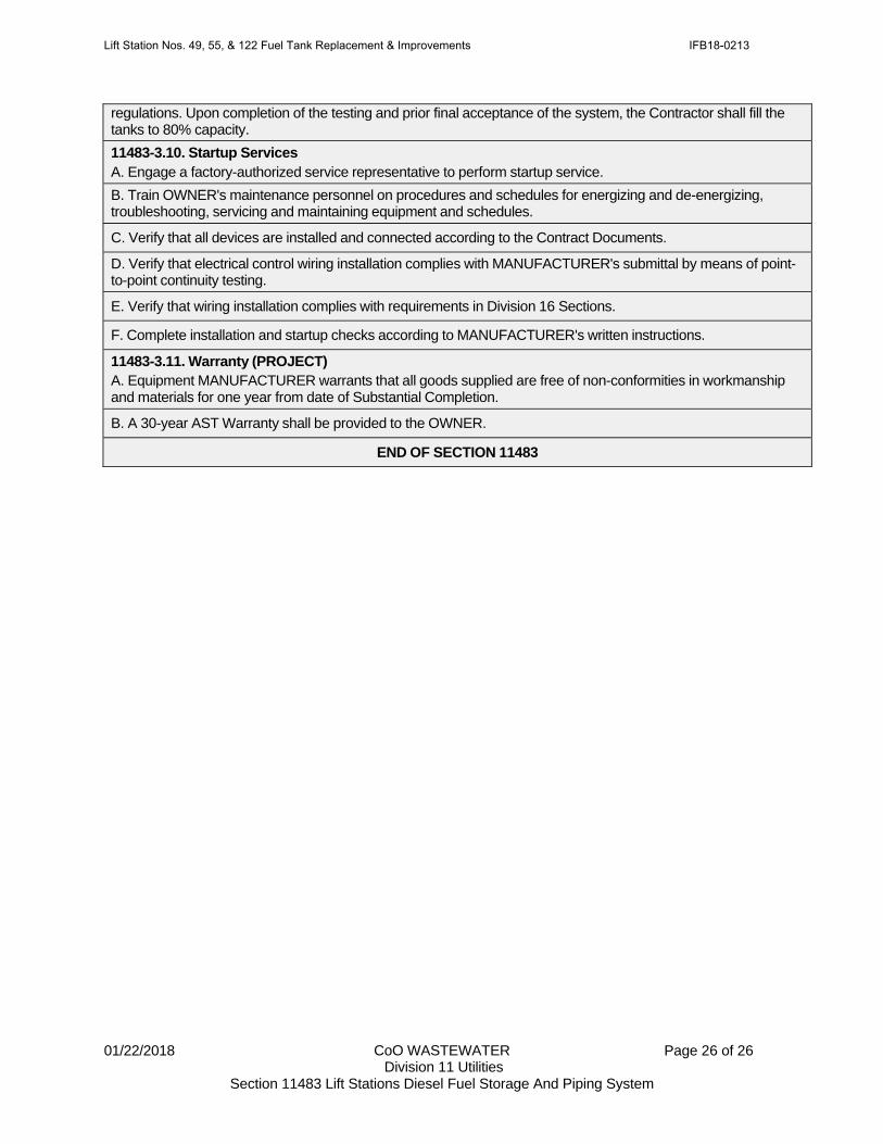
regulations. Upon completion of the testing and prior final acceptance of the system, the Contractor shall fill the tanks to 80% capacity.
11483-3.10. Startup Services A. Engage a factory-authorized service representative to perform startup service.
B. Train OWNER's maintenance personnel on procedures and schedules for energizing and de-energizing, troubleshooting, servicing and maintaining equipment and schedules.
C. Verify that all devices are installed and connected according to the Contract Documents.
D. Verify that electrical control wiring installation complies with MANUFACTURER's submittal by means of point- to-point continuity testing.
E. Verify that wiring installation complies with requirements in Division 16 Sections.
F. Complete installation and startup checks according to MANUFACTURER's written instructions.
11483-3.11. Warranty (PROJECT) A. Equipment MANUFACTURER warrants that all goods supplied are free of non-conformities in workmanship and materials for one year from date of Substantial Completion.
B. A 30-year AST Warranty shall be provided to the OWNER.
END OF SECTION 11483
Lift Station Nos. 49, 55, & 122 Fuel Tank Replacement & Improvements IFB18-0213