EPICS record/device/driver Support [email protected], many slides copied from [email protected].
SECTION 11 5311.12
GLOVEBOX INSTALLATION
*************************************************************************************************************LANL MASTER SPECIFICATION
Word file at http://engstandards.lanl.govThis template must be edited for each project. In doing so, specifier must add job-specific requirements. Brackets are used in the text to indicate designer choices or locations where text must be supplied by the designer. Once the choice is made or text supplied, remove the brackets. The specifications must also be edited to delete specification requirements for processes, items, or designs that are not included in the project -- and specifier’s notes such as these. To seek a variance from requirements in the specifications that are applicable, contact the Engineering Standards Manual Mechanical HPOCH. Please contact POC with suggestions for improvement as well.
When assembling a specification package, include applicable specifications from all Divisions, especially Division 1, General requirements.
This specification serves as a template. The specification was prepared by an organization operating under a quality assurance program that meets the requirements of 10 CFR 830 (suitable for ML-1 through ML-4 projects). Implementation of this specification requires modification to the specification to meet project-specific requirements. Responsibility for application of this specification to meet project-specific requirements lies with the organization modifying or implementing the specification. The organization modifying the specification shall apply a graded approach to quality assurance based on the management level designation of the project. When this specification is used with nuclear facilities subject to 10 CFR 830, modification to this specification must be performed by an individual or organization operating under a quality assurance program that meets the requirements of that CFR.
This specification primarily defines requirements for installation of stainless steel gloveboxes used for confinement of nuclear materials within DOE-owned and operated, non-reactor, nuclear facilities at Los Alamos National Laboratory (LANL).
The glovebox installation process covers overall glovebox assembly design, installation design, installation of the glovebox into the facility, installation of glovebox equipment, connection of facility systems to the glovebox, and final inspection and testing. These activities may be performed by a variety of personnel. The scope of this specification involves installation of the glovebox into the facility, connection of facility systems, and final inspection and testing. Activities associated with design for installation and installation of equipment into the glovebox is not presented herein. If these activities are desired to be performed by the glovebox installation subcontractor, then these scopes of work must be added.
Many of the specification sections below have been developed with reference to standards established by the LANL TA-55 Facility Operations engineering group. These standards are available for reference by contacting them.
****************************************************************************************************************
LANL Project I.D. [ ] Glovebox Installation[Rev. 2, October 14, 2009] 11 5311.12-1

PART 1GENERAL
1.1 SUMMARY
A. Section Includes
1. The purpose of this specification is to provide installation requirements to the glovebox installer for nuclear material gloveboxes in LANL facilities. In many cases, the specification will reference other sections of the LANL Construction Manual for more specific requirements, since gloveboxes typically interface with many different engineered systems.
1.2 DESCRIPTION
A. Scope
1. This specification establishes the technical requirements for the on-site storage, rigging, handling, transportation, materials for installation, installation, examination, testing, inspection, and quality assurance (QA) of gloveboxes.
2. The technical requirements of this specification are applicable to gloveboxes used for the primary and secondary confinement of nuclear materials. Additional technical requirements are provided in the subcontract drawings. Any additional requirements specific to a given glovebox are identified in subcontract documentation identified in Division 1 documents.
B. Acronyms
1. ACGIH: American Conference of Governmental Industrial Hygienists
2. AGS: American Glovebox Society
3. ANSI: American National Standards Institute
4. ASHRAE: American Society for Heating, Refrigeration and Air Conditioning Engineers
5. ASME: American Society of Mechanical Engineers
6. ASNT: American Society of Nondestructive Testing
7. ASTM: ASTM International (formerly American Society for Testing and Materials)
8. AWG: American Wire Gauge
9. AWS: American Welding Society
10. B&PVC: Boiler and Pressure Vessel Code
11. CAM: Continuous air monitor
12. CFR: Code of Federal Regulation
LANL Project I.D. [ ] Glovebox Installation[Rev. 2, October 14, 2009] 11 5311.12-2
13. CFV: Critical flow venturi
14. CMTR: Certified material test report
15. CoC: Certificate of conformance
16. CRL: Central Research Laboratories
17. CWI: Certified Welding Inspector
18. DOE: Department of Energy
19. DOP: de-octyl phthalate
20. DOS: Di (2-ethylhexyl) sebacate
21. FAS: Fixed-head Air Sampling
22. FNPT: Female national pipe thread
23. FPM: Feet per minute
24. FM: Factory Mutual
25. HEPA: High-efficiency particulate air
26. HDPE: High-density polyethylene
27. ISMS: Integrated Safety Management System
28. LANL: Los Alamos National Laboratory
29. LVPPCCW: Limited volume positive pressure circulating chilled water
30. MASS: Material Accountability Safeguards and Security
31. ML: Management level
32. NACE: National Association of Corrosion Engineers
33. NDE: Nondestructive examination
34. NEC: National Electrical Code
35. NFPA: National Fire Protection Association
36. NPCCW: Negative pressure circulating chilled water
37. NPT: National pipe thread
38. NQA: Nuclear Quality Assurance
39. OSHA: Occupational Safety and Health Administration
LANL Project I.D. [ ] Glovebox Installation[Rev. 2, October 14, 2009] 11 5311.12-3

40. P/N: Part number
41. PC: Performance category
42. PF: Plutonium Facility
43. POC: Point of contact
44. PPCCW: Positive pressure circulating chilled water
45. PPE: Personnel protective equipment
46. PRD: Pressure relief device
47. PRV: Pressure regulating valve
48. psi: Pound(s) per square inch
49. psig: Pound(s) per square inch gauge
50. QA: Quality Assurance
51. QC: Quality Control
52. TA: Technical Area
53. RWP: Radiation work permit
54. S: Security
55. SMACNA: Sheet Metal and Air Conditioning Contractor’s National Association
56. SOP: Standard operating procedure
57. SS: Stainless steel
58. STD: Standard
59. UL: Underwriters Laboratories
60. USQD: Unreviewed safety question determination
61. w.c.: water column
62. WOG: Water, oil or gas
LANL Project I.D. [ ] Glovebox Installation[Rev. 2, October 14, 2009] 11 5311.12-4
C. References
Codes, specifications, and standards referred to by number or title form a part of this specification; they include the following references. Use the latest revision at the time of codes, specifications, and standards referenced below and within this specification award of subcontract, unless otherwise stated.
1. 10 CFR 830.122: Quality Assurance Criteria
2. 29 CFR 1910: Occupational Safety and Health Administration (OSHA) Standards
3. 29 CFR 1910.253: Oxygen Fuel Gas Welding and Cutting
4. 29 CFR 1910.254: Arc Welding and Cutting
5. ACGIH: Industrial Ventilation, A Manual of Recommended Practice
6. AGS-G001: Guideline for Gloveboxes
7. AGS-G005: Standard of Practice for the Design and Fabrication of Gloves and Transfer Sleeves
8. AGS-G006: Standard of Practice for the Design and Fabrication of Gloveboxes for the Containment of Materials that Emit Low-Penetrating Ionizing Radiation
9. ASHRAE Standards
10. ANSI/ASME B1.20.3: Dryseal Pipe Threads (inch)
11. ANSI/ASME B16.5: Pipe Flanges and Flanged Fittings
12. ANSI/ASME B16.11: Forged Steel Fittings, Socket-Welding and Threaded
13. ANSI/ASME B16.21: Nonmetallic Pipe Gaskets for Pipe Flanges
14. ANSI/ASME B16.22: Wrought Copper and Copper Alloy Solder Joint Pressure Fittings
15. ANSI/ASME B30.20: Below the Hook Lifting Devices
16. ASME B31.3: Process Piping
17. ASME Boiler and Pressure Vessel Code (B&PVC), Section IX: Qualification Standard for Welding and Brazing Procedures, Welders, Brazers, and Welding and Brazing Operators
18. ASME NQA-1: QA Program Requirements for Nuclear Facilities
19. ASNT SNT-TC-1A: Recommended Practice
20. ASTM A36: Structural Steel
LANL Project I.D. [ ] Glovebox Installation[Rev. 2, October 14, 2009] 11 5311.12-5
21. ASTM A53: Pipe, Steel, Black and Hot-Dipped, Zinc-Coated Welded and Seamless
22. ASTM A167: Stainless and Heat-Resisting Chromium-Nickel Steel Plate, Sheet, and Strip
23. ASTM A182: Forged or Rolled Alloy Steel Pipe Flanges, Forged Fittings and Valves, and Parts for High-Temperature Service
24. ASTM A193: Alloy-Steel and Stainless Steel Bolting Materials for High-Temperature Service
25. ASTM A269: Seamless and Welded Austenitic Stainless Steel Tubing for General Service
26. ASTM A312: Seamless and Welded Austenitic Stainless Steel Pipes
27. ASTM A325: High-Strength Bolts for Structural Joints
28. ASTM A403: Wrought Austenitic Stainless Steel Piping Fittings
29. ASTM A513: Electric-Resistance Welded Carbon and Alloy Steel Mechanical Tubing
30. ASTM A527: Steel Sheet, Zinc-Coated (Galvanized) by the Hot-Dip Process, Lock-Forming Quality
31. ASTM A569: Steel, Carbon (0.15% max), Hot-Rolled Sheet and Strip, Commercial Quality
32. ASTM B16: Free-Cutting Brass Rod, Bar and Shapes for Use in Screw Machines
33. ASTM B32: Solder Metal
34. ASTM B68: Seamless Copper Tube, Bright Annealed
35. ASTM B75: Seamless Copper Tube
36. ASTM B88: Seamless Copper Water Tube
37. ASTM B453: Copper-Zinc-Lead Alloy (Leaded-Brass) Rod
38. ASTM D2000: Standard Classification System for Rubber Products in Automotive Applications
39. AWS D1.1: Structural Welding Code Steel
40. AWS QC 1: Standard for AWS Certification of Welding Inspectors
41. DOE O 420.1: Facility Safety
42. DOE Order 6430.1A: General Design Criteria (Division 11)
LANL Project I.D. [ ] Glovebox Installation[Rev. 2, October 14, 2009] 11 5311.12-6
43. DOE-STD-1021: NPH Performance, Categorization Guidelines for SSCs
44. DOE-STD-1090: Hoisting and Rigging
45. DOE-STD-3020: Specification for HEPA Filters Used by DOE Subcontractors
46. Factory Mutual (FM)
47. Federal Specification WW-V-35C: Valve, Ball
48. Federal Test Method Standard Number 601: Rubber Sampling and Testing
49. LANL Engineering Standards Manual, including Pressure Safety Chapter, ASME B31.3 Process Piping Guide, and Welding Chapter
50. LANL H SD 100 , Integrated Safety Management System Description Document with embedded 10 CFR 851 Worker Safety and Health Program
51. LANL SD 130: Nuclear Criticality Program
52. LANL P 121: Radiation Protection
53. LANL P 101-4: Forklifts and Powered Industrial Trucks
54. LANL P 101-6: Personnel Protective Equipment
55. NACE MR0175: Standard Materials Requirements Sulfide-Stress Cracking Resistant Metallic Materials for Oilfield Equipment
56. NFPA 70: National Electrical Code
57. NFPA 101: Code for Safety to Life from Fire in Buildings and Structures
58. SMACNA Standards
59. UL: Underwriters Laboratories
60. Uniform Plumbing Code (IAPMO)
1.3 RELATED SECTIONS
A. Section 01 1116: Work by Owner
B. Section 01 6000: Product Requirements
C. Section 01 2500: Substitution Procedures
D. Section 01 7700: Closeout Procedures
E. Section 01 7839: Project Record Documents
F. Section 11 5311.08: Glovebox Fabrication
LANL Project I.D. [ ] Glovebox Installation[Rev. 2, October 14, 2009] 11 5311.12-7

G. Section 11 5311.14: Glovebox Gloves
H. Section 11 5311.16: Glovebox Feedthroughs, Hermetically-Sealed
I. Section 11 5311.18: Glovebox Atmosphere Regenerable Purification Systems
J. Section 11 5311.12: Glovebox Installation
K. Section 13 4800: Sound, Vibration and Seismic Control
L. Section11 5311.17: Glovebox Instrumentation
M. Section 40 0513: Common Work Results for Process Piping [future]]
N. Section 22 0554: Identification for Plumbing, HVAC, and Fire Piping and Equipment
O. Section 40 0511: Compression Fittings on Copper and Stainless Steel Tubing
P. Section 23 4133: High Efficiency Particulate Filtration
Q. Section 23 3225: Bag-in Bag-out Housing
R. Section 23 0593: Testing, Adjusting and Balancing for HVAC
S. Section 26 0553: Raceway and Boxes for Electrical Systems
T. Section 26 0553: Raceway and Boxes for Electrical Systems
U. Section 26 0519: Low Voltage Electrical Power Conductors and Cables
V. Section 26 0533: Raceway and Boxes for electrical Systems
W. Section 26 0526: Grounding and Bonding for Electrical Systems
X. Section 26 5100: Interior Lighting
1.4 HOISTING AND RIGGING
A. Perform onsite hoisting and rigging of gloveboxes in accordance with LANL P 101-4, “Forklifts and Powered Industrial Trucks,” and DOE-STD-1090, “Hoisting and Rigging.”
B. Rig and hoist gloveboxes in a manner to prevent temporary or permanent distortion of the glovebox shell (distortion can affect the leak integrity of the glovebox).
1.5 PREREQUISITES
A. Prior to performing work, plan the installation process and perform work in accordance with LANL’s Integrated Safety Management System (ISMS) as described in HLANL H SD 100 , Integrated Safety Management System Description Document with embedded 10 CFR 851 Worker Safety and Health ProgramH.
LANL Project I.D. [ ] Glovebox Installation[Rev. 2, October 14, 2009] 11 5311.12-8
The author shall determine whether a Radiation Work Permit will be necessary to install the glovebox. An RWP may not be necessary for installation of a glovebox into a facility where radiation work was previously not performed.
B. Prior to performing work, develop and establish approval of a Radiation Work Permit (RWP).
C. Review drawings, details, manuals, and other materials required for installation of gloveboxes prior to purchasing materials or performing installation work.
D. When working with potentially contaminated systems, ensure catch bags, filters, or other mechanisms are in place to contain contaminants prior to performing work.
The author shall develop a list of submittals for each glovebox project since submittals will be project-specific. Submittals are intended to verify that appropriate materials are used and to report progress and actions performed during installation to the appropriate authority. The reviewing and approving authority for submittals may vary from facility to facility and from project to project. The author needs to define the routing of submittals from the submittal generator to the receiving official. The timing of submittals, numbers of copies, and whether review and/or approval is needed must be defined by the author.
1.6 SUBMITTALS
A. Provide reference to LANL Subcontract Number, Glovebox Number, Glovebox Title, and Drawing Number on correspondence.
B. Provide submittals in accordance with Project requirements.
C. For all materials used, provide Certified Material Test Report (CMTRs) or (Certificates of Conformance (CoC) if unavailable from manuafacturer) indicating compliance with required chemical and physical properties and the test(s) performed to the applicable nationally recognized standards.
D. Provide other submittals detailed in Quality Assurance below and throughout this Section.
The following quality assurance requirements are consistent with installation of an ML-2 glovebox. Where other quality assurance and quality control requirements are needed, modify the following section accordingly. For instance, the supplier may also apply a QA program in accordance with basic requirements of 10 CFR 830.122. Add requirements for QA Programs compliant with 10 CFR 830.122 to the specification as necessary.
1.7 QUALITY ASSURANCE / QUALITY CONTROL
A. QA Manual: Submit an uncontrolled copy of the supplier’s QA Manual for installation for approval. Address the following NQA-1 Basic Requirements in the QA Manual:
1. Basic Requirement 1: Organization
LANL Project I.D. [ ] Glovebox Installation[Rev. 2, October 14, 2009] 11 5311.12-9
2. Basic Requirement 2: Quality Assurance Program
3. Basic Requirement 4: Procurement Document Control
4. Basic Requirement 5: Instructions, Procedures, and Drawings
5. Basic Requirement 6: Document Control
6. Basic Requirement 7: Control of Purchased Items and Services
7. Basic Requirement 8: Identification and Control of Items
8. Basic Requirement 9: Control of Processes
9. Basic Requirement 10: Inspection
10. Basic Requirement 11: Test Control
11. Basic Requirement 12: Control of Measuring and Test Equipment
12. Basic Requirement 13: Handling, Storage, and Shipping
13. Basic Requirement 14: Inspection, Test, and Operating Status
14. Basic Requirement 15: Control of Nonconforming Items
15. Basic Requirement 16: Corrective Action
B. Address the following in the supplier QA Manual (it is acceptable to reference the procedures in the following sections in the manual):
1. Fabrication and Quality Control (QC) Procedures: Provide list of procedures to be followed and submit per Project submittal requirements. LANL in cases may waive submittal, where procedures have previously been evaluated. Maintain a list of quality procedures, including the revision number or date of approval.
2. Personnel Certifications: Ensure that supplier personnel assigned to glovebox installation including welding, assembly, testing, and inspections are fully qualified to perform their respective job functions. Submit required personnel certifications per Project submittal requirements.
3. Test Reports: Ensure that tests performed in support of the glovebox installation, welding, assembly, testing, and inspection are fully documented. Submit test reports per Project submittal requirements.
4. Material Certifications: Provide material certifications for installation materials including legible copies of mill test reports indicating chemical analysis, physical test data, and heat number.
5. As-Built Drawings: Submit as-built drawings to reflect modifications or deviations to the subcontract drawings during installation.
LANL Project I.D. [ ] Glovebox Installation[Rev. 2, October 14, 2009] 11 5311.12-10
6. QA Document Package: Submit documents identified in this specification as a part of the QA Document Package. Complete three bound or stapled document packages containing these documents required “with shipment” in accordance with Project submittal requirements. Mail one package to LANL and provide the other two packages with the glovebox shipping crate.
7. Torque Maps: Submit Torque Map identifying location of fastener, required torque, applied torque, and calibration data of torque wrench used to tighten fastener. Supply Torque Map for fasteners on windows, service panels, access panels, support stand anchors, support stand fasteners, and any other fastener with a specified torque in this specification.
8. Weld Map: Submit Weld Map identifying location of weld and heat number of materials being welded for all welds to glovebox shell or appurtenances.
PART 2 PRODUCTS
2.1 PRODUCT OPTIONS AND SUBSTITUTIONS
A. Comply with Section 01 2500, Substitution Procedures.
2.2 MATERIALS
The author shall size anchor bolts for their intended purpose. Anchors should be sized along with the seismic calculations performed in accordance with Section 11 5311.10. Anchor sizing shall include material selection, embedded length selection and load calculations. The following anchor specifications are for typical anchors used at LANL. Calculate specific anchor sizes for each project specific application.
A. Anchors
1. Stainless steel, undercut-type, [1/4-, 3/8-, 1/2-, 5/8- or 3/4-inch diameter] anchors with [X-inch] embedment length as manufactured by [Maxi-Bolt or Hilti], meeting the chemical and physical requirements of ASTM A193, ASTM A325 and ASTM A513. [Size and select anchors in accordance with manufacturer’s instructions and ESM Structural Chapter.]
Materials meeting ASTM specifications may be substituted with materials meeting ASME Boiler and Pressure Vessel Code, Section II, Part C, SA- specifications. For instance, SA-182 may be substituted for ASTM A182.
B. Utility Penetration Plugs
1. Stainless steel of same grade as the glovebox shell material, type 304 or type 316 and that meet the physical requirements of ASME B16.11.
2. Plugs shall also meet the chemical and physical requirements of ASTM A182 and ASTM A403 and be dual marked 304/304L or 316/316L accordingly.
3. Do not use cast material for utility penetration plugs.
LANL Project I.D. [ ] Glovebox Installation[Rev. 2, October 14, 2009] 11 5311.12-11

High-density polyethylene (HDPE) provides very good chemical resistance. Pressure rating: 150 psi at 77°F (25°C). Temp range: –65 to 190°F (–53 to 87°C).
4. For highly corrosive glovebox environments: high-density polyethylene (HDPE) utility plugs in lieu of stainless steel plugs on the interior of the glovebox only.
5. Use Teflon tape and TruBlu sealant in conjunction with threaded utility plugs and caps.
Glovebox primary supply and return confinement plenums consist of gloveboxes and conveyor tunnels which are served by a 100% once-thru exhaust system consisting of ductwork, HEPA filters, glovebox type plenae and fans.
C. Duct
1. Glovebox Supply & Return Ducted Plenums
a. Material of Construction
i. For glovebox supply and exhaust air ducts originating at the conveyor tunnel or gloveboxes and terminating in the exhaust airway: stainless steel pipe or tube ductwork per the design drawings
ii. Stainless steel pipe/tubing: Type 304L, circular duct with a minimum 16 gauge, with welded leak tight joints in accordance with ASTM A501-73.
b. Provide supply and exhaust plenums that are completely sealed and leak tested. Prior to final leak testing, the internals such as cooling coils, sprinklers, fire protection and all the associated piping, controls, sensing devices, electric wiring and fixtures are to be installed and connected.
c. Provide a leak test of the duct system to ensure the air tightness of all connections showing no measurable leak at 0.5 psig positive and negative pressure.
d. Employ additional weld examination criteria (i.e., visual, light level of at least 100 foot-candles and liquid dye penetrant in accordance with Appendix VIII, Section VIII of the ASME Boiler Pressure Code.) on both seal and strength welds. Complete all welding of internals to skin and penetrations of plenum before the final overall leak test.
2. Provide all duct construction, minimum material gauges, longitudinal joints, transverse joints, and reinforcing of sheet metal ductwork in accordance with ASHRAE and SMACNA standards.
LANL Project I.D. [ ] Glovebox Installation[Rev. 2, October 14, 2009] 11 5311.12-12
3. Construct all ducts, other than glovebox supply and return plenae, from black carbon steel, galvanized sheet, or stainless steel based on the temperature and reactivity of the gases being conveyed.
4. When the gases being conveyed are corrosive, use duct linings or coatings to extend duct service life as required.
5. Use round ducts unless prohibited by physical constraints.
6. Ensure all materials meet or exceed design specifications and are free from damage or manufacturing defects.
7. Material specifications for all ducts other than glovebox supply and return plenae:
a. Hot-rolled steel sheet in accordance with ASTM A569.
b. Hot-rolled steel plate in accordance with ASTM A36.
c. Galvanized sheet in accordance with ASTM A527.
d. Stainless steel in accordance with ASTM A167 or A269 for tubing.
The author shall specify the fluid service category for each piping system to which the glovebox will connect. The author shall consider the category of fluid service during selection of materials, components, and joints by virtue of certain prohibition, limitations, and conditions found throughout the ASME B31.3. ASME B31.3 however does not instruct the author on how to select specific materials.
The author shall consider the effects of erosion/corrosion, radiation, and thermal aging during the material selection process for all piping at LANL.
D. Piping
1. Piping shall meet ASME B31.3 Process Piping in all respects. It is highly recommended that installation follow LANL Engineering Manual Pressure Safety Chapter’s ASME B31.3 Process Piping Guide [and related B31.3 Spec Section (future)].
2. Provide pipe materials in accordance with ASME B31.3, Process Piping, and in accordance with the following fluid service category [Normal Fluid Service, Category D Service, Category M Service, High Pressure (K) Service].
3. Provide new piping components free from defects and contamination. Ensure that piping materials are listed components as identified in ASME B31.3.
4. Stainless Steel Tubing
a. For general, high-pressure service: seamless tubing per ASTM A269 type [304, 304L, 316 or 316L].
LANL Project I.D. [ ] Glovebox Installation[Rev. 2, October 14, 2009] 11 5311.12-13
b. For corrosive service: seamless stainless tubing per ASTM A269 Grade TP316.
5. Stainless Steel Piping
a. Seamless pipe per ASTM A312 grade [TP316 or TP316L].
Hard copper tubing in accordance with ASTM B88 is measured by nominal size; as a result the actual OD should be determined when specifying tube fittings, valves and other inline components.
The author shall determine which soft copper tubing is applicable to the installation. Soft copper tubing is to be used for short flexible connections including instrument leads from branch block valves to instruments. Soft copper tubing should also be used when it is necessary to use compression type fittings.
Soft copper tubing in accordance with ASTM B68 is measured by outside diameter. Compression type fittings should only be used on 0.035” wall soft copper tubing up to 1/2" O.D. in accordance with ASTM B68. For diameters larger than 1/2" a thicker wall must be specified for use with compression fittings.
Soft copper tubing in accordance with ASTM B88 is measured by nominal size, as a result the actual OD should be determined when using compression type fittings. Compression type fittings should only be used on tubing specified as annealed temper 0.
6. Copper Tubing
a. Hard copper tubing with hard temper, Type “L” wall thickness, seamless drawn, per ASTM B88.
b. Seamless soft copper tubing, either
i. ASTM B68 with soft temper, soft annealed, 0.035 inch wall thickness
ii. ASTM B88, Type “L” wall thickness, soft anneal temper 0.
7. Carbon Steel Piping
a. Black, seamless, carbon steel piping per ASTM A53, Type S, Grade B, schedule 40 wall thickness.
8. Vacuum Tubing 10 E-3 Torr through 1 atmosphere
a. Seamless drawn copper, ASTM-B88 hard temper, Type “L” wall thickness.
b. Provide copper tubing and tube fittings that are bright-dipped.
LANL Project I.D. [ ] Glovebox Installation[Rev. 2, October 14, 2009] 11 5311.12-14
c. Provide ball valves specially prepared for vacuum service with Ultrahigh Molecular Weight Polyethylene (UHMWPE) seats and stem packing, 316 stainless steel ball and stem, suitable for high vacuum.
9. Vacuum Tubing 10 E-6 Torr through 1 Torr
a. Seamless drawn copper, hard temper per ASTM-B88, Type “L” wall thickness
b. Copper tubing and tube fittings bright-dipped. Tubing cleaned in conformance with ASTM-B280 and ANSI-B9.1. Each length cleaned, capped or plugged, color-coded and marked “ACR”.
The following valve requirements are TA-55 specific and other similar valves may be selected for use at other LANL facilities
E. Valves
1. Provide valves as listed components in accordance with ASME B31.3.
2. Provide valves that are new, free from defects and contamination, and a standard product of the manufacturer.
3. Provide valves with all metal seals and seats in preference to other materials (especially Teflon/PTFE), whenever the service may carry or be contaminated directly with radioactive materials.
4. Ball Valves (Shut-off Service & Regulating Service)
a. Provide ball valves with Vespel, HDPE, or – if necessary -- reinforced-PTFE seats and stuffing box ring, 316 stainless steel ball and stem, furnished with individual wrenches for quarter-turn operation.
b. Provide ball valves designed for soft soldering or threading into lines without the need for disassembly. Provide ball valves with blowout-proof stem design and adjustable packing gland.
c. Provide the following ball valves for shut-off service:
i. Class 150 rating, threaded, soft soldered or brazed ends ANSI/ASME B16.22, bronze 3-piece body, rated 600 psig cold, non-shock, with locking plate to meet OSHA standards. Manufacturer: Apollo, Worcester
LANL Project I.D. [ ] Glovebox Installation[Rev. 2, October 14, 2009] 11 5311.12-15

ii. Class 150 rating, threaded or socket weld, 1000 psig WOG, cold non-shock. Carbon steel 3-piece body, rated 150 psig saturated steam, vacuum service to 29 inches Hg, federal specification: WW-V-35C, Type: II, Composition: CS, Style: 1, meets NACE MR0175 with SS trim. Manufacturer: Apollo, Worcester
iii. Class 150 rating, threaded or socket weld, 1000 psig WOG, cold non-shock. Stainless steel 3-piece body, 150 psig saturated steam, vacuum service to 29 inches Hg, federal specification: WW-V-35C, Type: II, Composition: CS, Style: 1, Meets NACE MR0175. Manufacturer: Apollo, Worcester
5. Bellows Valves
a. Provide the following bellows valves for shut-off service:
i. Flanged bonnet high vacuum in-line type, ANSI B16.22 solder ends, forged brass 1-piece body and nipples with Viton-A O-ring bonnet seal and disc. Manufacturer: Veeco
ii. Flanged bonnet high vacuum angle type, ANSI B16.22 solder ends, forged brass 1-piece body and nipples with Viton-A O-ring bonnet seal and disc. Manufacturer: Veeco
b. Provide all-welded double-bellows-sealed valves for tritium service or other radioactive or toxic gas service outside the glovebox.
6. Gate Valves
a. Provide the following gate valves for shut-off service:
i. Inside screw rising stem union bonnet solid disc type, 150#, threaded ends, bronze body. Manufacturer: Hammond
7. Globe Valves (Regulating Service)
a. Provide the following globe valves for regulating flow:
i. Brass body, packless, solder cup connections. Manufacturer: Henry
ii. Stainless steel body, type 316, bellows seal FNPT connections. Manufacturer: Powell
iii. Angular, brass body, angled solder cup connections, packless. Manufacturer: Henry
8. Check Valves (Reverse Flow Service)
a. Provide the following check valves to prevent backflow:
i. Brass body, spring-loaded, poppet-type, Buna-N Seal, FNPT 3000# connection. Manufacturer: Nupro
LANL Project I.D. [ ] Glovebox Installation[Rev. 2, October 14, 2009] 11 5311.12-16
ii. Stainless steel body, spring Loaded, poppet-type, Viton seal, FNPT connection. Manufacturer: Nupro
9. Solenoid Valve:
a. Provide the following solenoid valves for shut-off service and valve actuation:
i. 120 V, 60 HZ, 0-275 psi, Nitrogen, Ar, He, Compressed Air, brass body, FNPT connections. Manufacturer: ASCO
ii. 120 V, -4 in. Hg to 0 psi, Air. 316 stainless steel body, FNPT connections. Manufacturer: ASCO
10. Pressure Control Valve:
a. Provide the following pressure control valves for active regulating service
i. Non-relieving, bubble tight, 4 to 50 psi range, brass body, FNPT connections. Manufacturer: TESCOM
ii. Non relieving, bubble tight, 4 to 50 psi range, 316 stainless steel body, FNPT connections. Manufacturer: TESCOM
F. Fittings
1. Stainless Steel Pipe Fittings:
a. Forged stainless steel, ASTM-A182, Grade F316, 150# pattern, threaded ends, with general dimensions conforming to ANSI B16.3. Pipe fittings ¾-in and smaller.
b. Seamless wrought stainless steel, ASTM-A403, Grade WP316L, schedule 40s, butt-welding ends. Pipe fittings ¼-in through ¾-in piping.
c. Seamless wrought stainless steel, ASTM-A182, Grade F316, 3000#, socket-weld ends conforming to ANSI B16.11. Pipe fitting 1-1/2-in. and smaller.
2. Stainless Steel Tube Fittings:
a. Type 316 stainless steel compression type with separate front back ferrules. Provide “Dryseal” type pipe threads, where pipe threads are required, conforming to ANSI B1.20.3.
3. Hard Copper Fittings:
a. Seamless wrought copper, ASTM-B75, solder type, with dimensions conforming to ANSI B16.22.
LANL Project I.D. [ ] Glovebox Installation[Rev. 2, October 14, 2009] 11 5311.12-17

4. Soft Copper Fittings
a. Brass compression type with separate front and back ferules. Provide “Dryseal” type pipe threads, where pipe threads are required, conforming to ANSI B1.20.3.
5. Carbon Steel Fittings:
a. Forged carbon steel, ASTM-A181, Grade I, 2000#, threaded ends, conforming to ANSI B16.11.
6. Refer to Section 40 0511, Compression Fittings on Copper and Stainless Steel tubing, for specification of compression fittings on copper and stainless steel tubing.
7. Provide face-seal fittings that utilize a metal gasket (copper) for radioactive material service tubing, including tubing that may carry or be contaminated with plutonium.
8. Provide fitting components conforming to the materials physical and chemical properties identified in appropriate ASTM Standards.
9. Do not connect, mix, or interchange fitting parts (caps, plugs, ferrules, bodies, etc) of tube fittings made by different manufacturers (such as Parker to Swagelok).
10. Provide bent tubing in lieu of mechanical fittings for mere changes in routing direction, such as bends and offsets.
G. Copper Caps
1. Wrought, solder type, seamless copper caps in accordance with ASTM B75, with dimensions conforming to ANSI/ASME B16.22.
H. Nipples:
1. Stainless steel nipples, type 316, in accordance with ASTM A182 and ANSI/ASME B16.3, MNPT & FNPT 150# connection.
2. Brass nipples in accordance with ASTM B16, and ASTM B453, NPT 3000#.
I. Unions
1. Seamless, wrought or cast copper, ground joint solder type unions with integral seat and dimensions conforming to ANSI B16.22.
J. Wiring
1. Refer to Section 26 0519 – Low Voltage Electrical Power Conductors and Cables.
LANL Project I.D. [ ] Glovebox Installation[Rev. 2, October 14, 2009] 11 5311.12-18
K. Conduit
1. Refer to Section 26 0533 – Raceway and Boxes for Electrical Systems.
L. Receptacles
1. Refer to Section 26 2726 – Wiring Devices.
M. Wireways
1. Refer to Section 26 0533 –Raceway and Boxes for Electrical Systems.
N. Instruments
1. Refer to Section 11 5311.17 – Glovebox Instrumentation.
O. Light Fixtures
1. Locate general lighting exterior to gloveboxes (low heat), mounted above or near a window section built into the glovebox shell. Install general fluorescent or quartz halogen.
2. Provide local or directional task lighting of fluorescent or incandescent type. Secure task lighting to the glovebox. Power interior lighting from duplex outlets inside the glovebox.
3. Install lighting levels with approximately 100 foot-candles at work surface. Provide methods of adjusting lighting both inside and outside glovebox to minimize glare.
4. Install luminaries with baffles to diffuse light and ensure light tube is not directly visible to a user’s eye.
5. Install incandescent lights where space is limited in bulkhead-type fixture. Avoid close proximity to flexible glovebags because melting or fire could cause breach of containment.
6. Avoid high intensity light fixtures near glovebox windows, they have been known to break glovebox window due to excessive heating.
The author shall determine the limitation and applicability in selecting neoprene gasket materials. Limitations on its use are temperature (150F) and chemical resistance.
P. Gaskets
1. For glovebox windows and service panel installations: Black neoprene gasket material of 1/8 to 1/4-inch thickness, 40 to 60 (Shore A) durometer in accordance with ASTM D2000
2. Provide torque requirements specified for tie-down based on the desired bolt stress. Establish bolt size and allowable stress in accordance with engineering
LANL Project I.D. [ ] Glovebox Installation[Rev. 2, October 14, 2009] 11 5311.12-19
practice. (the Nuclear Air Cleaning Handbook recommends maximum 80% compression or about 20 lb/in2).
Q. HEPA Filters
1. Provide in accordance with Section 23 4133 – Filters.
2. Provide 8-inch and 12-inch diameter filters meeting dimensional requirements of LANL drawing 26Y-202057. Provide HEPA filters tested offsite in accordance with DOE-STD-3020.
3. Refer to Part 3.2 “Glovebox Integrity,” Section F HEPA Filters for detailed installation instruction.
4. Provide in-line HEPA filters intended for the removal of aerosol particles from gas streams (i.e., gas analyzers, dry vacuum systems), which are potentially contaminated with hazardous material. Install filter units on vacuum sampling lines at the process enclosure confinement boundary. Refer to Section 11 5311.08 – Glovebox Design, §3.19.F, “Ventilation and Filter Housings,” for design and fabrication considerations.
a. Install standard NPT connections for low vacuum service if desired and Cajon VCR® metal face seal fitting end connection for high vacuum leak-tight service.
b. HEPA filter units shall pass a pressure leak test by the manufacturer and installation agency. Refer to this specification §3.12.F, “Piping Examination, Inspection, and Testing,” for instructions.
R. Fasteners
1. Carbon steel and stainless steel fasteners as specified in Section 11 5311.10, Glovebox Fabrication. Prevent the use of counterfeit or suspect fasteners by following the guidance in Section 11 5311.10.
2. Provide Certified Material Test Reports (CMTR) for fasteners to LANL for review and approval. With prior LANL approval, provide Certificates of Conformance (CoC) in lieu of CMTRs for fasteners. Review and approval of submittals by qualified engineering authority.
S. Welding Materials
1. Welding materials including filler rod meeting the requirements of Section 11 5311.10, Gloveboxes and ESM Chapter 13, Welding and Joining.
2. Provide Certified Material Test Reports (CMTR) for weld filler to LANL for review and approval. Review and approval of submittals by qualified engineering authority.
T. Electrical Feedthroughs
1. Refer to Section 11 5311.16 – Glovebox Feedthroughs Hermetically-Sealed.
LANL Project I.D. [ ] Glovebox Installation[Rev. 2, October 14, 2009] 11 5311.12-20

U. Glovebox Atmosphere Regenerable Purification Systems (Dri-Trains)
1. Refer to Section 11 5311.18 – Glovebox Atmosphere Regenerable Purification Systems.
V. Glovebox Gloves
1. Refer to Section 11 5311.14 – Glovebox Gloves.
PART 3 EXECUTION
3.1 STRUCTURAL
A. Provide support stands to withstand the design basis earthquake to prevent the enclosure from toppling over per the LANL Engineering Manual Structural section. In special nuclear facilities, the seismic requirements and the rationale for PC-3 as defined in DOE-STD-1021 is that the glovebox must remain standing.
B. Install glovebox stands with longitudinal or transverse reinforcements to satisfy LANL seismic criteria. Design according to seismic results obtained by Finite Element Analysis.
C. Obtain field measurements from existing enclosures to qualify the new enclosure support leg height.
1. The distance from the laboratory floor to the bottom of the existing spool piece.
2. The distance from the floor to the bottom of the existing glovebox or the height of the existing glovebox leg.
D. Determine the new glovebox leg height by subtracting measurement 4 (above) from measurement 3 (above). Properly attach support stands to the floor in accordance with subcontract drawings. Fasteners shall be per drawings, related Division 3 sections on post-installed anchors, or as detailed in Part II-Materials.
E. Provide shim packages underneath glovebox stand base plates for final alignment. Do not exceed 1/4-inch. If shims thicker than 1/4-inch are required, then weld shims to base of support stand legs in accordance with the following requirements:
1. Provide continuous weld around perimeter of shim between shim and base pad of support stand leg.
2. Provide half-bevel weld of thickness equal to the thickness of the thinnest material being welded (thickness of either the shim or support stand base pad, whichever is thinner).
3. Perform welding and provide weld procedure specifications, procedure qualification records, and welder performance qualification records in accordance with ESM Chapter 13 Welding and Joining and Section 11 5311.10. – Glovebox Fabrication.
LANL Project I.D. [ ] Glovebox Installation[Rev. 2, October 14, 2009] 11 5311.12-21
Thicker shim packages lead to excessive binding moments on anchor bolts and could cause them to fail during a seismic event.
F. Make surveys of the laboratory floor to determine the location of reinforcing bar imbedded in the concrete laboratory floor (e.g., Ground-penetrating radar – GPR). Do not drill anchor holes that intersect with the reinforcing rod.
G. Specify torque requirement for tie-down requirements based on the desired bolt stress. Base stress on not more than 80% of the yield strength of the bolt material. Establish bolt size and allowable stress in accordance with engineering practice.
H. Document torque applied to fasteners on a Torque Map of the glovebox. Indicate the location of fastener, torque applied, and calibration data for torque wrench used to tighten fastener. Submit Torque Map for review and approval.
I. Properly secure heavy objects on top of or inside enclosure.
3.2 GLOVEBOX INTEGRITY
The author shall determine and develop specific maintenance requirements for the type and size of gloveboxes and the various types of supporting equipment for the glovebox. After maintenance affecting the primary containment capability of a glovebox, leak tests and/or dye penetrant test may have to be performed. Qualified, certified, and trained personnel wearing the proper protective equipment and radiation monitoring devices shall perform all maintenance activities.
A. Welding and Surface Finish
1. Maintain surface finish on gloveboxes in accordance with the requirements of LANL Facility Engineering Manual, Section 11 5311.10 - Glovebox Fabrication. Maintain surface finish requirements in accordance with requirements defined on Drawing 26Y-202001.
2. Grind and polish all welds between the glovebox and exterior or interior appurtenances attached during installation. Perform all grinding and polishing operations in accordance with Section 11 5311.10.
3. Provide surfaces free of weld spatter, burrs, sharp edges, corners, loose stranded wires and projecting pins.
4. Polish damaged surfaces to a 32 micro-inch, arithmetic average, finish.
5. Provide a Weld Map to document all welds applied to the glovebox during installation. Document the location of the weld on the glovebox and the heat number of material being welded.
The author shall determine and specify the type of gloves to be installed in the glovebox, depending upon requirements for resistance to chemicals, radiation shielding, and ergonomics. The type of glovebox and the process operation conducted inside the glovebox determines the
LANL Project I.D. [ ] Glovebox Installation[Rev. 2, October 14, 2009] 11 5311.12-22
type of glove used. In such areas as plutonium-238 labs, a more detailed procedure for installation is required, than specified below, due to the high specific activity of plutonium-238. The following procedure for glove installation is one used by TA-55, PF-4, Plutonium Facility. The author shall use this procedure unless other facility-specific procedures for glove installation exist at the site of glovebox installation.
Reference the American Glovebox Society, AGS-G005, “Standard of Practice for the Design and Fabrication of Gloves and Transfer Sleeves” and the LANL Facility Construction Specification, Section 11 5311.10, “Glovebox Fabrication,” for information pertaining to glove selection and use.
****************************************************************************************************************
****************************************************************************************************************Consider that in some cases, where beta emitters are being handled, unshielded glovebox gloves will reduce the extremity dose rate. Consult LA-UR-99-3596, Photon and Electron Shielding for Neptunium-237, for further information.
B. Gloves
1. Refer to Section 11 5311.14 – Glovebox Gloves.
2. Install gloves or gloveport plugs in all gloveports provided on the glovebox shell.
The author shall establish a formal glove inspection procedure with proper quality assurance review and approval. Gloves can be inspected using various techniques including visual inspection or other inspection methods defined in AGS-G005.
3. Inspect gloves prior to use for cracking, tears, punctures, and burns. Perform inspection in accordance with the facility approved glove inspection procedure. Complete and submit a glove inspection procedure and inspection report for review and approval.
4. Perform the following procedure for installing gloves in gloveports manufactured by Central Research Laboratories (CRL).
a. Place the bead of the glove into the narrow groove of the plastic support ring.
b. Apply a light coating of vacuum grease to the O-ring. Install the O-ring over the glove and onto the wide groove of the support ring. Make sure that the glove is not wrinkled under the O-ring and that the bead is still in the narrow groove. This unit will be referred to as the glove-support ring subassembly.
c. Retract the inner housing of the ejection tool by turning the hand wheel counterclockwise.
d. Retract the plunger and remove the swaging collar from the ejection tool by rotating it in either direction until it releases from the bayonets.
LANL Project I.D. [ ] Glovebox Installation[Rev. 2, October 14, 2009] 11 5311.12-23
e. Apply a very light coating of vacuum grease periodically to the inside surface of the swaging collar.
f. Install the glove-support ring subassembly into the swaging collar, orienting the thumb of the glove with the plunger notch on the swaging collar. This will result in a “thumb-up” position of the glove when installed.
g. Engage the swaging collar to the bayonets on the ejection tool and rotate until the plunger locks into the notch of the swaging collar
h. Check the thumb of the glove and the plunger for proper orientation.
i. Insert the glove into the inner housing.
j. Orient the bayonet of the swaging collar (the bayonet that is in line with the plunger) with the bayonet opening in the enclosure ring at approximately a 10 o’clock position and rotate the ejection tool clockwise to the stop pin. Ensure that the notch and plunger on the ejection tool is positioned at 12 o’clock when the tool is properly installed on the enclosure ring.
k. By working through the spokes of the ejection tool, apply a light pull force on the glove. Turn the hand wheel of the ejection tool clockwise until the hand wheel bottoms on the outer housing.
l. Retract the inner housing of the ejection tool with the hand wheel and remove the ejection tool from the enclosure ring.
The following procedures for window installation are used by TA-55, PF-4 Plutonium Facility. The author shall use these procedures unless other facility-specific procedures for window installation exist at the site of glovebox installation. The procedures below describe replacement of windows on gloveboxes. These procedures should be modified appropriately to describe installation of windows on new gloveboxes when new gloveboxes are being installed.
C. Windows
1. Install windows provided by the glovebox supplier on the glovebox in accordance with the following requirements. Reference Section 11 5311.10 for specifications associated with glovebox windows.
2. Preparation for Window Installations
a. Obtain proper replacement windows and gaskets
b. Verify sizes and dimensions of replacement parts
c. Establish a temporary confinement barrier large enough to cover both the new and old window/gasket
d. Obtain and prepare tools and equipment to perform the job
LANL Project I.D. [ ] Glovebox Installation[Rev. 2, October 14, 2009] 11 5311.12-24

e. Obtain proper authorization [i.e., Radiation Work Permit (RWP), fixed head readings, nose swipes, and/or survey maps]
f. Remove fireguard from the window gasket (zippered windows only) and clean this area
g. Clean the inside of the glovebox around the windows being changed
h. Wipe the window gasket and around the window area with an oil-soaked synthetic (non-cellulose) rag or cheesecloth to minimize loose contamination
i. Inspect the new window glass pane for proper size and shape, (proper radii is essential for proper seal and fit)
j. Prepare area for proper contamination control
k. Grease the grooves of the new gasket and attach it to the new window. For bolt-on windows, grease the new gasket and attach it to the new window.
l. Verify the negativity of the glovebox by checking the magnehelic gauge indication
m. Don appropriate personal protective equipment. Include respirator, cap and hood where appropriate.
n. Close guillotine or fire doors leading to trolleys and verify negative pressure within the enclosure.
3. Installation of a Bolt-On Window
a. Remove the screws and metal strips from the bolt-on window to be changed. Take caution with stainless steel screws, which may gall and seize within studs during removal. Remove the screws with care as appropriate (using cutting fluid).
b. Where applicable, check the screws and metal strips for contamination.
c. With vinyl tape handle, carefully pull back and remove the old window and gasket. Try not to touch the contaminated side. If a window sticks, use the window tool to pry the window loose.
d. Carefully place the old window and gasket into a plastic bag and seal the bag with tape.
e. Install the new window, with its greased gasket attached.
f. Place the bagged-out window and gasket into another plastic bag and again seal with tape.
g. Check the surrounding area and personnel for contamination. Replace any contaminated protective clothing, as necessary.
LANL Project I.D. [ ] Glovebox Installation[Rev. 2, October 14, 2009] 11 5311.12-25
h. Replace each metal strip in the same location from which it was removed. Snug the screws down finger-tight. Use caution; over-tightening can crack the window or cause failure of the weld stud or screw.
i. Using an alternating pattern, tighten the screws with either a standard wrench or torque wrench enough to stop leakage around the gasket. When using a torque wrench, apply the recommended ANSI torque of 25 inch-pounds +/- 5 inch-pounds to the screws. The objective is to tighten the bolts enough to stop leakage around the gasket.
j. If cracks are evident or produced. Inspect window penetration and work to flatness tolerance. Refer to § 3.2.A.
k. Document torque applied to fasteners on a Torque Map of the glovebox. Indicate the location of fastener, torque applied, and calibration data for torque wrench used to tighten fastener. Submit Torque Map for review and approval. Inspect the window glass for cracks prior to use.
4. Installation of a Zippered Window
a. Remove and inspect the zipper seal. If deterioration is obvious, discard the zipper seal and use a new one.
b. Carefully cut the window gasket using a sharp knife on all corners, cutting through the gasket to the surface of the glovebox.
c. Carefully push the window and gasket into the glovebox. Inside the glovebox, support both window and gasket during removal.
d. Apply vacuum grease to the outer groove of the zipper window gasket.
e. Install the greased groove of the new gasket into the window opening. To minimize the spread of contamination, try not to touch the inside of the glovebox.
f. Insert the new window into the center of the greased groove of the gasket and slide the glass toward one side of the gasket. When the glass reaches the end of the gasket, use the plastic window tool to finish inserting the glass into the gasket.
g. Replace the zipper seal or use a new one.
h. Monitor for contamination.
i. Inspect the window glass for cracks prior to use.
D. Service and Access Panels
1. Plug unused penetrations in service panels with plugs as defined in the materials section of this specification, both inside the glovebox and outside.
LANL Project I.D. [ ] Glovebox Installation[Rev. 2, October 14, 2009] 11 5311.12-26

2. Install hermetically-sealed electrical feedthroughs in openings in service panels in accordance with Section 11 5311.16 – Hermetically Sealed Glovebox Feedthroughs.
3. Attach pipe and tubing to female threaded couplings on service panels in accordance with requirements set forth in ASME B31.3. Apply Teflon tape and TruBlu sealant to threads of male pipe couplings prior to installation (other materials in high rad areas).
4. Attach service and access panels to glovebox using gaskets provided with the glovebox from the glovebox manufacturer.
5. Utilize high-crown acorn nuts, supplied with glovebox from glovebox manufacturer, for attachment of service and access panels.
6. Torque service and access panel nuts to 25-inch pounds +/- 5 inch pounds.
7. Document torque applied to fasteners on a Torque Map of the glovebox. Indicate the location of fastener, torque applied, and calibration data for torque wrench used to tighten fastener. Submit Torque Map for review and approval.
8. Use caution; over-tightening can crack the window or cause failure of the weld stud or screw.
9. Perform post-modification helium leak test of the glovebox including installed service panels and hermetically-sealed feedthroughs in accordance with requirements defined in § 3.12.
E. Gaskets
1. Install gaskets with all service panels, access panels, and glovebox primary confinement penetrations.
2. Compress gaskets 25% nominal and no more than 50% of its uncompressed thickness.
HEPA filters are used for a variety of gloveboxes (i.e., air atmosphere, isolated air, inert gas flush, high purity inert atmosphere, etc.). The exhaust for most gloveboxes is through 8-inch or 12-inch diameter HEPA filters. The glovebox atmosphere is drawn from the glovebox through a HEPA filter located on top of each glovebox mitigating contamination of the ventilation system. HEPA filters are located on gloveboxes in accordance with DOE Order 6430.1A and DOE O 420.1. The author shall determine the appropriate size of HEPA filter and housing for a particular process. Discussion here will be reserved for standard 8-inch or 12-inch diameter primary exhaust filters for most gloveboxes as detailed in LANL TA-55 Drawing Nos. 26Y-202057, 26Y-202059 and 26Y-202130. It is recommended that each facility develop and implement its own filter preferences and filter changing procedure.
F. HEPA Filters
1. Refer to Section 43 3113 – Gas and Liquid Purification Filters.
LANL Project I.D. [ ] Glovebox Installation[Rev. 2, October 14, 2009] 11 5311.12-27

2. Use HEPA filters that meet nuclear facility grade requirements as described in DOE-STD-3020 and the LANL HEPA Filter Procurement Standard.
3. Qualify all personnel who will change exhaust HEPA filters in accordance with facility specific procedures.
The process to install or replace a contaminated filter in a push-through filter housing is described below; for new fabrications, much can be edited out. The basic idea is: A cover is removed on the top of the filter housing. The glovebox system remains essentially sealed due to a second inline HEPA filter that blocks airflow and maintains pressure negativity. A new third filter and spacer are stacked atop the existing filters. The stack is pushed down, driving the first filter into the glovebox. The old filter is discarded, the second filter becomes the active filter, and the third filter blocks the opening of the filter housing.
4. Installing or Replacing Glovebox Exhaust Filter to Primary Ventilation
a. Complete a Hazard Screening Checklist prior to commencing installation / removal procedures.
b. Gluing the Gasket to the Filter and Spacer.
i. While wearing surgical gloves and safety glasses, inspect each Viton® chevron gasket for defects.
ii. Using Eastman 910 cement, glue the chevron gaskets to the filter spacer and the HEPA filter according to the steps that follow.
iii. Place the HEPA filter on a worktable with the airflow arrow pointing up.
iv. Place the spacer on a worktable with the closed end up.
v. Gently stretch a chevron gasket over each end of the HEPA filter and the spacer, with the chevron lip pointing up in the direction of the airflow. Keep the Eastman 910 cement away from your skin and eyes. Use it only in a well-ventilated area.
vi. Position the chevron gaskets within 1/2-inch of, and parallel to, the HEPA filter ends.
vii. By pressing your finger on the outside edge of the gasket, make a gap between the top chevron gasket and the wall of the HEPA filter or spacer.
viii. Run a small continuous bead of Eastman 910 glue along the gasket until it is completely encircled. Allow at least 10 minutes for the glue to dry. Before starting to change the HEPA filter, make certain that the glue has completely hardened and the gasket is completely sealed.
LANL Project I.D. [ ] Glovebox Installation[Rev. 2, October 14, 2009] 11 5311.12-28
ix. Spread a light coat of silicone grease on the HEPA filter and spacer chevron gaskets.
c. Prepare the area
i. Check if the glovebox requires special filters. Special filters are required in the following situations:
Inert-atmosphere: filters with galvanized shells
Aqueous: filters with stainless-steel shells
Plutonium-238: filters with special radiation-resistant glue
ii. Check for contamination by checking the HEPA filter housing, cover, and glovebox top. Don required personnel protective equipment (PPE).
iii. Ensure that negative pressure can be maintained inside the glovebox during the filter change. For gloveboxes using inert gas, adjust the oil bubbler and photohelic control of the bubbler bypass. Refer to the following section for details on pressure relief devices.
iv. Check the condition of the fire screen for corrosion and other damage. Replace the fire screen as required.
d. Removing a Used Exhaust HEPA Filter: Utilize three operators for performing the steps described below.
i. Climb on top of the glovebox and unbolt the HEPA filter housing cover. Follow facility safety guidelines for reaching HEPA filters on top of glovebox.
ii. Inspect for contamination
iii. If the cover is contaminated immediately perform decontamination.
iv. Hand the HEPA filter housing cover down to the other operator on the floor, or place the cover in a safe position where it cannot be knocked down.
e. Installing a New HEPA Filter
i. Without touching or puncturing the HEPA filter media in the HEPA filter housing, place the new spacer on top. Ensure that the open end is placed into the HEPA filter housing facing down and that the side-opening lines up with the exhaust port on the side of the HEPA filter-housing assembly.
LANL Project I.D. [ ] Glovebox Installation[Rev. 2, October 14, 2009] 11 5311.12-29
ii. Gently push down on the spacer to dislodge the bottom HEPA filter. Support the used, dislodged HEPA filter as it is pushed down into the glovebox.
iii. Continue to push the spacer into the HEPA filter housing assembly until the new HEPA filter can be fitted inside.
iv. Push the new HEPA filter into the HEPA filter housing and orient it with the airflow arrow pointed up. NOTE: The used spacer is replaced along with the bottom HEPA filter. The new HEPA filter is moved down into the position occupied by the old HEPA filter.
v. Push the new HEPA filter and spacer down until the used (or old) spacer can be grasped from inside the glovebox.
vi. Replace the fire screen and tighten the nuts that hold the fire screen in place.
vii. Push the HEPA filter-housing cover down until it meets the housing flange.
viii. Bolt the HEPA filter-housing cover plate into place. To ensure an even seal, tighten the bolts in staggered sequence.
ix. Survey all surface areas near the HEPA filter housing for contamination that may have been released. If any is found, immediately decontaminate.
x. Survey the personnel involved in the HEPA filter change for any alpha contamination.
xi. Perform appropriate bag-in and bag-out procedures to dispose of used filters.
G. Shaft Penetrations
1. Design and install shaft penetrations that require rotational or translational mechanisms to penetrate the glovebox so that equipment is integrated into the glovebox.
2. Provide equipment with suitable anchorage and motor mount. Equipment may be heavy, long, tall, or possess unique features that may require a special glovebox design and seismic restraint feature.
3. Align the motor and shaft assembly to prevent excessive vibration of the glovebox or distortion of the glovebox. Excessive vibration can cause glovebox window breakage and may affect sensitive analytical balances.
4. Equip static (bolted support housing) and dynamic (rotational shaft) assemblies of the penetration with high integrity seals (i.e., O-ring, hermetic, ferrofluidic, etc.) to maintain pressure integrity of the glovebox.
LANL Project I.D. [ ] Glovebox Installation[Rev. 2, October 14, 2009] 11 5311.12-30

5. Include primary, secondary and tertiary seal confinement at both the static and dynamic assemblies at seal installation. Include a gasket or O-ring seal at the support plate. Refer to a standard model below that illustrates the seal requirement.
6. Penetration Wall Principle:
7. Subject the shaft penetration, with the equipment in place and operational, to a post-modification helium leak test along with the glovebox in accordance with the requirements identified in the testing portion of this specification.
8. Provide for engineering shaft penetration design acceptance and final approval with specification by the appropriate discipline and subject matter expert.
H. Hoods
1. Ensure proper face velocity across hood openings during installation. Maintain velocity of air through openings in accordance with the Industrial Ventilation Manual from the American Conference of Governmental Industrial Hygienists (ACGIH).
2. Certify hood as operational by inspection of airflow and posting of airflow inspection. Ensure airflow is inspected yearly and verify inspection is within one year of current date prior to use of hood. If the hood has a sash, check to be sure it is raised no higher than the sticker allows.
LANL Project I.D. [ ] Glovebox Installation[Rev. 2, October 14, 2009] 11 5311.12-31
3.3 MECHANICAL SERVICES (ALL GLOVEBOXES)
A. Connection to Existing Equipment
1. Airlocks
a. General Information
i. When material is transferred to a controlled atmosphere glovebox where maintaining that atmosphere is operationally desired, an airlock is often used. An airlock allows for an item to move from one atmosphere box to another with minimum disruption to a glovebox atmosphere. Typically, airlocks are used as a buffer area between glovebox lines that contain an air atmosphere and gloveboxes that contain an inert or other non-reactive gas atmosphere.
ii. The airlock is located between gloveboxes that must not be over (or under) pressurized.
iii. Use engineering controls for all airlock systems to prevent inadvertent pressurization of systems.
iv. Moving items into and out of an airlock requires operation of airlock doors that could pinch operators or glovebox gloves. Movement of material through an airlock is a mechanical operation involving opening and closing doors. Thus, the potential of getting a hand or a glove caught in the door (or door mechanism) exists. Ensure adequate clearance between the gloveport nearest the sliding door.
v. Provide airlock doors with pneumatic actuators that are structurally stable. Trim length of door as required to ensure proper travel of pneumatic cylinder shaft.
vi. Ensure no stops in the door guides that restrict or bind opening of the door.
vii. Provide airlock spool pieces of sufficient length to install glovebox and accommodate connection of utility lines to side service panel.
viii. Ensure gas supplies entering airlock have pressure-regulating valves, check valves gauges near workstations and filters.
ix. Set all pressure-regulating valves (PRV) for gas services except instrument air at less than 25 psig.
x. Provide one gauge downstream of all PRVs to verify indications of the PRV gauges.
xi. Ensure all airlock service lines are traced to facility services headers and labeled.
LANL Project I.D. [ ] Glovebox Installation[Rev. 2, October 14, 2009] 11 5311.12-32

xii. Provide air-operated cylinders with PRVs and flow-regulating valves.
xiii. Air-operated (pneumatic) switches for glovebox doors should be mounted approximately 10-in. below the top of the glovebox legs.
xiv. Ensure air-operated cylinders with shafts penetrating contaminated enclosures have HEPA filters and exhaust to proper ventilation system.
xv. Use appropriate gasket material and shape for airlock connecting ring assembly to provide adequate seal. Mount connector rings at 90 3 to axis of enclosure.
b. Connection to Airlocks
i. Perform ground penetrating radar (GPR) to locate concrete structural members prior to setting anchor bolts.
ii. Locate approximate location of glovebox structural support plates and approximate leg support heights. Cut each support leg to individually measured distance.
iii. Install legs to complete support structure, weld base plates.
iv. Approximate and align glovebox to airlock in the longitudinal and transverse directions.
v. Drill holes at designated location to anchor support structure.
vi. Level box using shim packs; utilize shim packs to no more than 1/4-in.
vii. Secure and seal door to adjacent gloveboxes or dropboxes before breaking seal to airlock.
viii. Acquire standard glovebox parts for new spool piece (airlock) with new gaskets (metal or neoprene) and clamps
ix. Finalize alignment of gloveboxes with lifting jacks or table. Verify load capacities of lifting devices to appropriate rated loads and safety factors.
x. Back enclosure to airlock and install gaskets and standard ring assembly.
xi. Clamp and torque standard ring assembly “snug tight” or 60 in-lbs. minimum.
xii. Document torque applied to fasteners on a Torque Map of the glovebox. Indicate the location of fastener, torque applied, and
LANL Project I.D. [ ] Glovebox Installation[Rev. 2, October 14, 2009] 11 5311.12-33

calibration data for torque wrench used to tighten fastener. Submit Torque Map for review and approval.
xiii. Perform post-modification helium leak test on the airlock in accordance with the testing section this specification.
2. Open-Front Gloveboxes
a. Open-Front Gloveboxes (i.e., transfer boxes, introductory boxes and hoods) are used to insert or remove materials and/or equipment into the glovebox line. Inlet air for these enclosures is provided from the laboratory rooms. The exhaust air from these enclosures passes through a HEPA filter and is drawn into a recirculation system plenum.
b. Open-front gloveboxes use a 24-in. square filter. These boxes need a large capacity filter to handle the volume of air drawn in to ensure the required 125 feet per minute inflow of air when the door is open. Refer to Section 23 4133 –Filters for HEPA filter requirements for use on open-front gloveboxes.
i. For chemical hoods with no radioactive material, the glovebox ventilation system must provide 125-fpm-minimum airflow through full open doors.
ii. For chemical hoods where radioactive material is available, the glovebox ventilation system must provide for 150 fpm through the normal opening.
c. Ensure the introductory hood is kept clean to prevent cross-contamination when introducing items, and to prevent contamination release in the event of ventilation failure.
d. Storage of chemicals is not allowed in introductory hoods except with the permission of a LANL industrial hygienist and facility manager.
e. All work performed in open-front hoods requires supporting documentation. This documentation includes:
i. Activity-specific SOPs, special work permits, or radiological work permits
ii. Current radiological survey
iii. Proof of current performance tests (yellow sticker)
iv. Material Safety Data Sheets for all hoods designated for chemical use
v. Certification by the Industrial Hygiene Group for airflow and/or chemical use
LANL Project I.D. [ ] Glovebox Installation[Rev. 2, October 14, 2009] 11 5311.12-34
f. Only use open-front hoods displaying a current performance acceptance (yellow) sticker and comply with any conditions stated on the certification.
g. Never use toxic or flammable gases in introductory hoods. Fumes may be recirculated into the laboratories. These fumes present a health hazard.
h. Before introducing items through hoods, consult with a radiological control technician to determine the radiological controls necessary for the introduction, including, but not limited to, types of personal protective clothing and the necessity of radiological control technician coverage.
i. All hoods should contain one 115V duplex outlet.
3. Conveyors
a. Refer to Section 41 2225– Hoists and Trolleys for requirements pertinent to hoists and trolleys used inside of gloveboxes.
b. Conveying equipment located in enclosures (conveyer tunnels) similar to a glovebox. Conveyer tunnels are used to interconnect gloveboxes or drop boxes.
c. Vertical portions of the tunnel connect the overhead system to the glovebox rows at drop boxes. These drop boxes are the transfer points where items are hoisted up to the trolley for movement to another glovebox or work area.
d. The elevated stainless-steel tunnels are typically 2½ feet wide, 3 feet high, and roughly 8 feet above the floor. To form a continuous tunnel, peripheral flanges join the various lengths of tunnels to each other and to the gloveboxes.
e. Spring-loaded contacts pick up electrical current to operate the motors and the hoist. Power and control signals are carried in a series of bus bars that traverse the length of the trolley tunnel. Electric drive motors are programmed to increase and decrease the trolley speed for smooth, jerk-free movement.
f. Trolley systems are typically powered from a portable control console located on the lab floor near the conveying system. The console may contain:
i. Main circuit breaker,
ii. Control transformer,
iii. Solid-state variable-voltage dc drive
iv. Contactors, and
LANL Project I.D. [ ] Glovebox Installation[Rev. 2, October 14, 2009] 11 5311.12-35

v. Solid-state programmable controller.
g. Provide push-button control stations located at each drop box station and at the control console. The numbered push buttons shall match the numbered drop boxes serviced by the trolley, and each button will light up when the trolley is at the corresponding drop box. The trolley will not move until the hoist is in the UP position and locked in place.
h. Provide a trolley bucket that can be lowered into any drop box in an individual system.
i. Typical hoist and trolley shall have a load limit of 500 pounds (227 kilograms) with the trolley bucket removed. The load limit for the trolley with the bucket attached is 200 pounds (91 kilograms) in addition to the weight of the bucket. This will prevent glovebox containment breach at the system interface.
j. Use lifting equipment meeting the requirements of ASME B30.20 and the following requirements:
i. Metal tag or placard displaying the load limits, proof load, date of last proof test and retest interval.
ii. Positive mechanical locking device to prevent inadvertent lowering of the load in the event of lifting mechanism failure.
iii. Permanent mechanical stops. This will prevent a trolley from falling off the end of a monorail or contacting the interior of the glovebox.
k. Use independent mechanical and electrical braking systems for electrically powered lifting mechanisms.
l. Use braking systems capable of braking and safely holding a minimum of 150 percent of rated load.
m. Use hooks for lifting equipment, including hooks used on slings and cables, with positive safety latching devices across the hook opening.
n. Evaluate gloveboxes to ensure that there is sufficient translation height for the object requiring movement, adequate height for the lifting device in the proper configuration, operating height for the hoist, trolley height, and monorail height.
o. Attachment points for monorails are typically spaced 8-in. to 12-in. apart and utilize studs to support welded structural plates or angles.
p. Provide guards made from Lexan or other suitable materials to protect windows.
q. Cable hoists are preferred over chain hoists.
LANL Project I.D. [ ] Glovebox Installation[Rev. 2, October 14, 2009] 11 5311.12-36
r. To prevent glove tears, grind smooth any sharp points, corners, and edges.
s. Ensure that that objects requiring movement inside gloveboxes designed with L-shaped floor plans and provided with a curved monorail do not contact the inside corner of the glovebox.
t. Subject conveyor tunnels enclosures to a post-modification pressure test. No measurable leaks at 0.5 psig positive and negative.
u. Specify torque requirement for tie-down requirements based on the desired bolt stress. This stress based on not more than 80% of the yield strength of the bolt material. Establish bolt size and allowable stress in accordance with engineering practice.
v. Document torque applied to fasteners on a Torque Map of the glovebox. Indicate the location of fastener, torque applied, and calibration data for torque wrench used to tighten fastener. Submit Torque Map for review and approval.
For additional information the author shall reference the American Glovebox Society latest edition, “Standard of Practice for the Design and Fabrication of Gloveboxes for the Containment of Materials that Emit Low-Penetrating Ionizing Radiation,” AGS-G-006, and LANL Facility Construction Specification Sections 11 5311.08 – Glovebox Design and 11 5311.10 – Glovebox Fabrication.
4. Gloveboxes and Dropboxes
a. NOTE: A glovebox system includes the gloveboxes, drop boxes, conveyer tunnels, trunk lines, and open front boxes. Drop boxes and trunk lines typically interconnect gloveboxes so that hazardous and radioactive material and equipment may be transferred from one glovebox to another.
b. Completed glovebox installations, including service tie-ins, support systems functions, etc., shall be certified by a subject matter expert (systems engineer) according to an established checklist. Certification must be approved prior to final connection to the glovebox ventilation system and startup of glovebox operations
c. Architectural Requirements
i. The face of the glovebox is aligned with the face of the drop box.
ii. Provide a minimum of 3-in to 6-in. space between the backs of gloveboxes (i.e., a glovebox line in the center of a laboratory) or between the glovebox and laboratory wall.
iii. Ensure aisles between individual gloveboxes are wide enough so that two workers will not collide when simultaneously withdrawing from the gloves.
LANL Project I.D. [ ] Glovebox Installation[Rev. 2, October 14, 2009] 11 5311.12-37

iv. Provide sufficient space for a spool piece or airlock between the tunnel and the glovebox.
v. Ensure adequate access height underneath the glovebox for equipment installation, bagouts, sample removal, chemical storage, maintenance, and decontamination.
vi. Use standard enclosure port spacing of 50-inches from laboratory floor to centerline of gloveport.
vii. Ensure that installation of gloveboxes and associated services (i.e., gas, liquid, and electrical utility features below the glovebox) does not require removal or rerouting to accommodate a deep glovebox.
viii. Provide a ½-in. thick rubber mat on the floor and a portable work platform of varying height, front face of enclosure.
ix. Ensure adequate vertical spacing to install glovebox HEPA filter housing, bubbler, butterfly valve, and flex line where applicable.
x. Ensure adequate room to access the glovebox filter housing for filter replacement.
xi. Provide for gloveboxes height, width, and length that can be moved through the facility. Consideration for the decommissioning of glovebox along with protective packaging through the laboratory doors, corridors, elevator, basement aisles, etc.
xii. Ensure that installation of glovebox does not interfere or require the movement of other gloveboxes in the glovebox line.
xiii. Locate gloveboxes and /or glovebox equipment at the end of glovebox lines near laboratory wall 24-in from the doors at the corner of the laboratory room.
d. Mechanical
i. Install gloveboxes and hoods to achieve the following face velocities
For chemical hoods with no radioactive material, the glovebox ventilation system must provide 125-fpm minimum airflow through full open doors.
For chemical hoods where radioactive material is available, the glovebox ventilation system must provide for 150 fpm through the normal opening.
Setup ventilation systems on gloveboxes so that there is a flow of 125 fpm ± 25 fpm through the largest credible breach (gloveport or bagport). Set-up glovebox normal operating
LANL Project I.D. [ ] Glovebox Installation[Rev. 2, October 14, 2009] 11 5311.12-38
flow, inlet resistance (filter and damper setting), and glovebox pressure such that the to achieve 125 fpm ± 25 fpm face velocity is achieved when the breach occurs, without having to actuate dampers (except in closed loop inert gas systems).
Author shall reference the Glovebox Standard details from the 26Y-202000 drawing series to refer to design details (i.e., Counterbalance Doors, Round and Square Airlock Assemblies, Exhaust Filter Assemblies, etc) for standard design and installation criteria.
ii. Unistrut welded to the back legs for holding pipe and electric headers should be flush with the side of the legs (i.e., not extend to the rear beyond the legs).
iii. Piping from nipples on the front of boxes that have hydrogenous shielding should be tubing; it should be as close to the box surface and stand as possible.
iv. Torque window frame and service panel or plate covers bolts and studs to 25 5 in.-lb. Secure bolts and studs with acorn nuts.
v. Document torque applied to fasteners on a Torque Map of the glovebox. Indicate the location of fastener, torque applied, and calibration data for torque wrench used to tighten fastener. Submit Torque Map for review and approval.
vi. HEPA Filters must be leak tested. One method uses Di (2-ethylhexyl) sebacate (called DOS testing), which replaced de-octyl phthalate, or DOP testing. Refer to Section 23 4133 – Filters for further requirements.
vii. Fabricate flat gaskets for bolted covers and service panels of black neoprene, 1/8-inch to ¼-inch thick, 40 to 60 durometer, (Shore A) and conforming to standard ASTM D2000. Other gasket material may be used for special environments. (Ref. Part 3, Section 3.2.c, “Gaskets”).
viii. Gas service lines into the gloveboxes must be no larger than 3/8-in. diameter, unless equipped with a flow restriction device. All gas supply lines must have pressure regulation, check valves, gauges, flow meters, and filters near workstations.
ix. Perform fit-up of compression fittings in accordance with Section 40 0511 of the LANL Construction Specifications.
x. Set pressure regulating valves for gas services except process air at a maximum of 25 psig. Provide at least one gauge downstream of all PRVs to verify indications of the PRV gauges.
xi. Pipe industrial water piped into enclosure with “deadman” valves to prevent flooding.
LANL Project I.D. [ ] Glovebox Installation[Rev. 2, October 14, 2009] 11 5311.12-39

xii. No positive pressure cooling water, except for limited volume systems, is piped into enclosures.
xiii. Positive pressure chilled circulating water is used to cool equipment exterior to the enclosure.
xiv. Chilled and heated piping is properly insulated.
xv. House and wet vacuum lines are trapped to prevent flooding of lines and enclosures.
xvi. Flanges of wet vacuum and liquid carrying lines are plastic wrapped.
xvii. Supply lines for air driven stirrers, vibrators, pumps, etc., inside gloveboxes have solenoid valves interlocked to glovebox pressure.
xviii. Vacuum pumps have metal piping to enclosures and exhaust through metal piping and HEPA filters the proper ventilation system.
xix. Air operated cylinders have PRVs and flow regulating valves.
xx. Air operated cylinders with shafts penetrating contaminated enclosures have HEPA filters and exhaust to the proper ventilating system.
xxi. Pressurized piping, vessels, columns, etc., have been evaluated and leak tested for operating pressures.
xxii. Piping from nipples, on the front of boxes that have hydrogenous shielding, should be tubing only, which should be as close to the box surface and stand as possible
xxiii. Use bent tubing in lieu of elbows unless otherwise indicated.
xxiv. Provide isolation valves for independently controlling liquids and gases to any process system or experiment inside a glovebox.
xxv. Use welders and brazers certified in accordance with the ASME Boiler and Pressure Vessel Code, Section IX, and ESM Chapter 13, Welding and Joining.
xxvi. Provide dielectric connections wherever joining dissimilar metals. Pitch lines in direction of flow.
xxvii. Identify piping in accordance with facility mechanical standards.
e. Electrical Requirements
i. Interlock all glovebox furnaces that have a high vacuum unit attached to cut off the power if vacuum is lost (pressure rise
LANL Project I.D. [ ] Glovebox Installation[Rev. 2, October 14, 2009] 11 5311.12-40
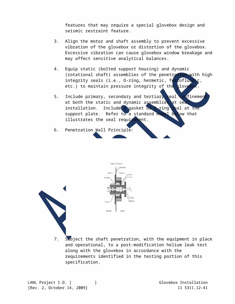
above a set point). Provide a bypass switch to allow over ride of this feature.
ii. All single section drop boxes should contain one 115V duplex outlet. All double or multiple section drop boxes should contain two 115V duplex outlets.
iii. Verify hermetically-sealed electrical feedthroughs are helium leak tested and leak tight following installation in glovebox penetrations and service panels in accordance with §3.12.
iv. Properly identify circuits at penetrations and breaker panels
v. Voltage and wiring have been checked.
vi. Photohelic and solenoid wiring have been checked.
vii. Ground all enclosure frames.
f. Instrumentation and Control Requirements
i. Refer to Section 11 5311.17– Glovebox Instrumentation for further requirements.
ii. Instrumentation receptacles and cables require proper identification
iii. Instrument feedthroughs are site or factory tested and properly installed. Refer to Section 11 5301.16 – Hermetically-Sealed Glovebox Feedthroughs
iv. Tubing and/or conduit lines should not go up the front, operating side, or be located directly over a glove box window or connector ring gasket.
v. Use indicator gauge dials with an appropriate scale and visible from the front of the boxes.
vi. Air operated (pneumatic) switches for glove box doors should be mounted approximately 10-in. below the top of the glovebox legs.
vii. Pressure relief devices, i.e., bubblers, must be filled with oil to the proper level. Bubbler bypass piping is installed, when required, with manual and solenoid valves.
viii. Recirculating purifiers (Dri-Trains) must have HEPA filters, pressure regulating valves and flow meters (when required) in gas supply lines. Refer to Section 11 5311.18 – Glovebox Atmosphere Regenerable Purification Systems for further requirements.
LANL Project I.D. [ ] Glovebox Installation[Rev. 2, October 14, 2009] 11 5311.12-41

ix. “Zero” magnehelic and photohelic or other pressure controllers and test for proper operation of makeup and exhaust solenoid valves in order to respond to changes in pressure.
x. For glovebox operations (see Section 3.2.2), where the inside of the glovebox has the potential for a hydrogen build-up, install a hydrogen detector.
xi. For special enclosures exhibiting the potential for a hydrogen environment, ensure that Hydrogen alarm switches actuate solenoid valves on the hydrogen lines outside the building or in hydrogen supply cabinet.
g. Fire Protection Requirements
i. Refer to Section 11 5311.17 – Glovebox Instrumentation for further fire detector requirements.
ii. Each glovebox and drop box is required to have a thermal detector in a stainless steel well with an alarm set point of 190F if heat source is present (e.g., furnace).
iii. For gloveboxes without heat sources, the alarm set point shall be 140F. Perform operability tests at appropriate intervals.
iv. Use a spring or counter balanced-type fire damper restrained in the open position by fusible links and activated by heat on all drop boxes. Fusible links may be replaced with frangible links or some other equivalent signal activated powered release.
v. HEPA filters on gloveboxes must be protected by fire screens.
vi. Combustible loading inside gloveboxes is limited to the equipment and materials specifically required for glovebox operation and/or short-term storage. Installation of gloves must ensure that gloves do not contact hot surfaces inside the glovebox.
vii. Use a fire shield to protect zippered windows with neoprene gaskets where the gaskets are exposed to the interior of the glovebox.
viii. For equipment cooling water circuits, use over-temperature and loss of flow interlocks.
h. Special Installation Instructions
i. The vendor of must certify that the glovebox enclosure is helium leak-tight. A helium leak test must also be performed after the glovebox is installed in the operating facility.
LANL Project I.D. [ ] Glovebox Installation[Rev. 2, October 14, 2009] 11 5311.12-42
i. Environmental Requirements
i. Reference Part 3, Section 3.4 for instruction on internal environmental parameters.
B. Connection to Ventilation
1. Zone 1 or Primary Confinement
a. There are many techniques that may be used for connecting a containment enclosure to the exhaust ventilation system. The variables that should be considered prior to fabrication and installation are:
i. Ease of installation in the field.
ii. Temperature of gas being conveyed
iii. Temperature fluctuations of the conveyed gas.
iv. Temperature fluctuations of the surrounding environment.
v. Corrosive nature of the conveyed gas
vi. Equipment or other forces that will produce movement or vibrations in the ductwork.
b. Duct materials should follow the guidance of Section 2.1 part C.
c. Seal or gasket material should be selected to be compatible with anticipated corrosives and temperatures.
d. Expansion joints and flex connections should be used to minimize stresses in the ductwork due to vibration or thermal expansion and contraction.
e. Construct ducts, and use expansion joints, connections and seals in accordance with ASHRAE and SMACNA standards.
2. Zone 2 or Operator Environment
a. Because workers normally occupy Zone 2, connection to this zone would possibly jeopardize the accepted indoor air quality should not be permitted. If possible, this system should be restricted to providing only ventilation for workers.
b. Materials and techniques of construction should be in accordance with ASHRAE and SMACNA standards latest revisions.
C. General Piping and Tubing Connections
1. Piping and tubing should not go up the front, operating side, or located directly over a glovebox window or connector ring gasket (either interior or exterior to the glovebox).
LANL Project I.D. [ ] Glovebox Installation[Rev. 2, October 14, 2009] 11 5311.12-43

2. Ensure tubing is free of wrinkles, flats, and humps, and is properly supported and protected from damage.
3. Changes in direction or branch connections for gravity flow lines should be made with 45-degree fittings.
4. Dielectric fittings should be used at the glovebox penetration when supplying pipe or tubing of material dissimilar to the glovebox structure.
Note that development of a new LANL Construction Specification Manual section titled Limited Volume Chilled Water Unit (LVCWU) is planned. Completion of this specification section will require modification of the following section requirements.
D. Connection to Liquid Services
1. Water
a. To prevent inadvertent over pressurization or criticality, cooling water for processes internal to gloveboxes are limited to the following three methods:
i. Negative Pressure Chilled Circulating Water (NPCCW) may be piped directly into a glovebox to provide equipment/process cooling. The NPCCW system operates on a negative pressure, therefore, any leak in the system will result in drawing air into the NPCCW system, and prevent water from escaping from the NPCCW and filling the glovebox.
ii. Limited Volume Positive Pressure Chilled Circulating Water (LVPPCCW) may be piped directly into a glovebox for process/ equipment cooling via a sealed loop. The LVPPCCW is then, in turn, cooled via a heat exchanger located outside the glovebox with PPCCW. Although a leak in the LVPPCCW could result in water leakage into a glovebox, the volume of water is limited such that a criticality or over pressurization is not credible.
iii. Positive Pressure Chilled Circulating Water (PPCCW) is not allowed inside a glovebox except for a very limited volume system. If a PPCCW system has lines inside a glovebox, then a line break sensor with an automatic shutoff valve must be used. PPCCW may be used to cool internal processes/ equipment provided it is located external to the glovebox via a heat exchanger well or other means. With this configuration, any leak in the PPCCW system will be external to the glovebox and not present an over pressurization or criticality concern.
iv. As part of fire safety, cooling water circuits are provided with over temperature and loss of flow interlocks.
v. Provisions should be made for possible expansion of liquid services.
LANL Project I.D. [ ] Glovebox Installation[Rev. 2, October 14, 2009] 11 5311.12-44

vi. The glovebox should be provided with drain lines, as appropriate to the application.
b. Service Classification and Description: Water, Domestic and Industrial Hot and Cold, Negative Pressure Chilled Circulatory.
i. Use hard copper, ASTM-B88, hard temper, type “L” wall thickness. Use soft copper for short flexible connections including instrument leads from branch block valve to instruments. (Ref.; Part 2, Section 2.2.D., “Piping”)
ii. Operating ranges: Maximum Pressure, –5 to 120 psig, Maximum Temperature, 35 to 180 F
iii. Construction Code: ASME B31.3, Process Piping; and Uniform Plumbing Code (for hanger spacing only).
iv. Material Standards: ASTM B88, ASTM B32, ASTM B75, ANSI/ASME B16.22, ANSI/ASME B1.20.3.
c. Service Classification and Description: Limited Volume Chilled Circulating
i. Use hard copper, ASTM-B88, type “L” wall thickness. Use soft copper for short flexible connections including instrument leads from branch block valve to instruments. (Ref.; Part 2, Section 2.2.D., “Piping”).
ii. Operating ranges: Maximum Pressure, 0 to 125 psig, Maximum Temperature, 30 to 180 F
iii. Construction Code: ASME B31.3, Process Piping; and Uniform Plumbing Code (for hanger spacing only).
iv. Material Standards: ASTM-B88, ASTM-B32, ASTM-B75, ANSI-B16.22, ANSI/ASME B1.20.3.
d. For industrial water piped into enclosure, provide “deadman” valves to prevent flooding.
e. No positive pressure cooling water, except for limited volume systems, is piped into enclosures. [Refer to Section TBD – Limited Volume Circulating Water Unit.]
f. Positive pressure chilled circulating water is used to cool equipment exterior to the enclosure.
g. Conductive liquid cooling of internal glovebox components may be accomplished by means of attachment to the wall of the glovebox.
h. Ensure chilled or heated piping is properly insulated.
LANL Project I.D. [ ] Glovebox Installation[Rev. 2, October 14, 2009] 11 5311.12-45

2. Service Classification and Description: Hydraulic Fluid
a. Ensure that hydraulic fluid systems used around enclosures or process equipment have fire-resistant characteristics.
b. Ensure that parts of a system that operate on pressures lower than full system pressure are capable of withstanding full system pressure.
c. Separate hydraulic lines from other high-energy sources such as heat, electrical current, and chemicals.
d. Use fire-resistant hydraulic fluid for hydraulic systems.
The author shall develop specifications for connection of glovebox floor drains to facility systems. Consult with LANL Criticality Safety group and facility authorization basis when developing specifications for this section.
3. Floor Drains
a. Connect glovebox floor drains to facility systems in a criticality-safe fashion. Consult with LANL Criticality Safety group and facility authorization basis prior to connection of glovebox floor drains to facility systems.
E. Connection to Gas Services
1. Compressed Air - Service Classification and Description
a. Use hard copper, ASTM-B88, hard temper, type “L” wall thickness. Use soft copper for short flexible connections including instrument leads from branch block valve to instrument. (Ref.; Part 2, Section 2.2.D., “Piping”)
b. Operating ranges: Maximum Pressure, 0 to 60 psig, Maximum Temperature, ambient to 125 F
c. Construction Code: ASME B31.3, Process Piping; and Uniform Plumbing Code (for hanger spacing only).
d. Material Standards: ASTM-B88, ASTM-B32, ASTM-B75, ANSI-B16.22, and ANSI/ASME B1.20.3.
2. Instrument Air - Service Classification and Description
a. Use hard copper, ASTM-B88, hard temper, type “L” wall thickness. Use soft copper for short flexible connections including instrument leads from branch block valve to instrument. (Ref.; Part 2, Section 2.2.D., “Piping”)
LANL Project I.D. [ ] Glovebox Installation[Rev. 2, October 14, 2009] 11 5311.12-46
b. Operating ranges: Maximum Pressure, 0 to 60 psig, Maximum Temperature, ambient to 125 F
c. Construction Code: ASME B31.3, Process Piping; and Uniform Plumbing Code (for hanger spacing only).
d. Material Standards: ASTM-B88, ASTM-B32, ASTM-B75, ANSI-B16.22, and ANSI/ASME B1.20.3.
e. NOTE: Instrument air can be supplied at higher pressures to glovebox enclosures; ensure proper line configuration, (i.e., pressure regulator, check valve, gauges, flow meter, and filter near work stations. Include flow restriction device (orifice).
3. Dry Vacuum - Service Classification and Description
a. Use hard copper, ASTM-B88, hard temper, type “L” wall thickness. Use soft copper for short flexible connections. (Ref.; Part 2, Section 2.2.D., “Piping”)
b. Operating ranges: Maximum Pressure, 10-3 Torr thru 1 atmosphere, Maximum Temperature, ambient to 125 F
c. Construction Code: ASME B31.3, Process Piping; and Uniform Plumbing Code (for hanger spacing only).
d. Material Standards: ASTM-B88, ASTM-B32, ASTM-B75, ANSI-B16.22, and ANSI/ASME B1.20.3.
4. Wet Vacuum – Service Classification and Description
a. Use annealed stainless steel, ASTM-A269, Grade TP 316, with 70-74 Rockwell “B” hardness range, 0.049 wall thickness. (Ref.; Part 2, Section 2.2.D., “Piping”)
b. Operating ranges: Maximum Pressure, 4-in. Hg to 100 psig, Maximum Temperature, 35 to 125 F.
c. Construction Code: ASME B31.3, Process Piping; and Uniform Plumbing Code (for hanger spacing only).
d. Material Standards: ASTM-A312, ASTM-A182, ASTM-A269, ASTM-A193, ANSI-B16.21, ANSI-B16.5, 29 CFR 1910.253, 29 CFR 1910.254.
e. Transfer of liquid reagents to or from a glovebox may be performed with a wet vacuum in combination with a reagent device that is mounted on top of the glovebox.
f. Vacuum pumps plumbed into gloveboxes use metal piping, and the exhaust from the vacuum pumps is routed to a filtration device.
g. Flanges of wet vacuum and liquid carrying lines are plastic wrapped.
LANL Project I.D. [ ] Glovebox Installation[Rev. 2, October 14, 2009] 11 5311.12-47

h. Changes in direction or branch connections for vacuum lines should be made with maximum 45-degree fittings.
5. Helium - Service Classification and Description
a. Use hard copper, ASTM-B88, hard temper, type “L” wall thickness. Use soft copper for flexible connections including instrument leads from branch block valves to instrument. (Ref.; Part 2, Section 2.2.D., “Piping”)
b. Operating ranges: Maximum Pressure, 0 to 125psig, Maximum Temperature, 35 F to 135 F
c. Construction Code: ASME B31.3, Process Piping; and Uniform Plumbing Code (for hanger spacing only).
d. Material Standards: ASTM-B88, ASTM-B32, ASTM-B75, ANSI-B16.22, and ANSI/ASME B1.20.3.
e. NOTE: Helium in certain instances may be supplied at higher pressures to glovebox enclosures; ensure proper line configuration, (i.e., pressure regulator, check valve, gauges, flow meter, and filter near workstations. Include flow restriction device (orifice).
6. Argon - Service Classification and Description
a. Use hard copper, ASTM-B88, hard temper, type “L” wall thickness. Use soft copper for flexible connections including instrument leads from branch block valves to instrument. (Ref.; Part 2, Section 2.2.D., “Piping”)
b. Operating ranges: Maximum Pressure, 0 to 125psig, Maximum Temperature, 35 F to 135 F
c. Construction Code: ASME B31.3, Process Piping; and Uniform Plumbing Code (for hanger spacing only).
d. Material Standards: ASTM-B88, ASTM-B32, ASTM-B75, ANSI-B16.22, and ANSI/ASME B1.20.3.
7. Nitrogen - Service Classification and Description
a. Use hard copper, ASTM-B88, hard temper, type “L” wall thickness. Use soft copper for flexible connections including instrument leads from branch block valves to instrument. (Ref.; Part 2, Section 2.2.D., “Piping”)
b. Operating ranges: Maximum Pressure, 0 to 125psig, Maximum Temperature, 35 F to 135 F
c. Construction Code: ASME B31.3, Process Piping; and Uniform Plumbing Code (for hanger spacing only).
LANL Project I.D. [ ] Glovebox Installation[Rev. 2, October 14, 2009] 11 5311.12-48
d. Material Standards: ASTM-B88, ASTM-B32, ASTM-B75, ANSI-B16.22, and ANSI/ASME B1.20.3.
3.4 MECHANICAL SERVICES (INERT ATMOSPHERE GLOVEBOXES)
A. Glovebox Atmosphere Regenerable Purification System (Dri-Train) Interface
1. Refer to Section 11 5311.18 – Glovebox Atmosphere Regenerable Purification System
2. Complete isolation from adjacent gloveboxes, drop box, and conveyer tunnel and tight controls are necessary to provide for a high-purity inert recirculating gas regeneration system.
3. Control oxygen concentration in the [2] parts per million range, and nitrogen concentrations in the [30] parts per million range.
4. NOTE: Purification to remove oxygen and nitrogen is accomplished through use of a Dri-Train unit. The Dri-train unit uses a blower to recirculate the glovebox atmosphere through a dryer/oxygen scavenger (a molecular sieve and copper oxide reactant). The Dri-train unit is connected to the glovebox by piping.
5. Service Classification and Description
a. Use hard copper, ASTM-B88, hard temper, type “L” wall thickness. Use soft copper for flexible connections including instrument leads from branch block valves to instrument. (Ref.; Part 2, Section 2.2.D., “Piping”)
b. Operating ranges: Maximum Pressure, 0 to 125 psig, Maximum Temperature, 35 F to 180 F
c. Construction Code: ASME B31.3, Process Piping; and Uniform Plumbing Code (for hanger spacing only).
d. Material Standards: ASTM-B88, ASTM-B32, ASTM-B75, ANSI-B16.22, and ANSI/ASME B1.20.3.
6. Provide for glovebox exhaust through HEPA filter assemblies and a bubbler (pressure relief devices) to regulate pressure with a photohelic-activated bypass (Ref.: Section C of this section).
7. Establish bubbler bypass pressure setpoints (i.e., make-up gas will start to flow at –0.7 inch w.c., and it will build up pressure until it reaches –0.4-inch w.c. At –0.4-inch w.c., the make-up gas switches off and the bypass valve opens, lowering the pressure. Should a pressure build-up overwhelm the bypass, the bubbler is set to bleed off at –0.2-in w.c.)
8. Use bent tubing in lieu of elbows for all purified gas and chilled water unless otherwise indicated. Hard solder all purified gas and chilled water joints unless otherwise indicated. Butt weld exhaust vent joints unless otherwise indicated.
LANL Project I.D. [ ] Glovebox Installation[Rev. 2, October 14, 2009] 11 5311.12-49

9. Install flex connectors with solder cup ends for vent and purified gas piping at Dri-train unit.
10. Install quick disconnects “snap tight” with textile-braided neoprene hose for Positive pressure circulated chilled water supply/return at Dri-train unit.
11. Install the large 1-1/2 inch valves on Dri-Train gas lines as close to the glovebox nipples as possible. On gloveboxes using hydrogenous material, the shielding only extends slightly above the large windows on the front of the box; therefore, these valves will be operable if placed high on the box sides.
12. Use HEPA filters on recirculating purifiers, pressure regulating valves, and flow meters (when required) in gas supply lines. Refer to Section 23 4133.
13. Ensure that all connections for recirculating gas and regeneration are accessible through the back panel.
14. Ensure that the flow rate of inert gas through the regenerative chambers is adjustable through the range of 0 to 40 cubic feet per minute.
15. Ensure that the gas entering the return line to the glovebox is not more than 10 °C above ambient room temperature.
16. Regeneration gas must be nitrogen or argon with 3% to 5% maximum hydrogen content, pressure-regulated to 25 psig.
17. Vent lines from the process vent during regeneration (¼-inch NPT) and vacuum pump (1-inch NPT) should be connected to suitable exhaust lines in the facility.
18. Perform helium leak testing of the entire system in accordance with ASTM E499 (tracer probe mode). Test the system to verify no detectable leak greater than 1 x 10 (-6) std cc/sec when helium leak-tested with equipment capable of detecting a leak of 1 x 10 (-10) std. cc/sec.
B. Once-Through System Interface
1. The glovebox is isolated from adjacent gloveboxes and an inert gas flushed through the enclosure. Install a bubbler in the glovebox line after the HEPA filter on top of the glovebox to control pressure.
2. Provide a manual control valve to set the atmosphere in the glovebox to the desired composition. The bypass is closed and the supply flow rate is manually controlled to less than 5 cfm.
3. Once-through system interfaces maintain less than 5% oxygen or water vapor atmosphere environment.
4. Service classification and description as per Recirculating Gas Regeneration System Interface.
LANL Project I.D. [ ] Glovebox Installation[Rev. 2, October 14, 2009] 11 5311.12-50

5. Use bent tubing in lieu of elbows for all purified gas tubing unless otherwise indicated. Hard solder purified gas joints unless otherwise indicated. Butt-weld exhaust vent joints unless otherwise indicated.
6. Install a HEPA filter, check valve, pressure regulator, and flow meter in all once-through interfaces with gloveboxes in gas supply lines. Refer to Section 23 4133.
C. Pressure Relief Devices
The author shall determine the pressure requirements and applicability of utilizing a Bubbler as the pressure relief device (PRD) to control inert atmosphere gloveboxes.
1. Bubblers
a. Bubbler units provide glovebox overpressure relief when an inert atmosphere is used, or on any glovebox that might over pressurize. See illustration below.
b. The unit is constructed from a combination of stainless steel and aluminum structural material forming the housing and gauge with an inner Pyrex tube providing forming the liquid column.
c. The operation of the bubbler is based on Pascal’s Law. The column of liquid created by the imbalance of pressures will be directly proportional to the imbalance.
d. Preferred liquids used for balancing glovebox internal pressure with consideration for appropriate density, viscosity and flammability are:
i. Dow Corning 200
LANL Project I.D. [ ] Glovebox Installation[Rev. 2, October 14, 2009] 11 5311.12-51
ii. Duo Seal 1407
e. Unit assembly must be vacuum leak checked for a helium leak rate not to exceed 1 X 10⁻³ cc atm/sec.
f. The bubbler assembly is installed in the exhaust line of a glovebox. It is an integral part of an inert gas bypass line. The line is installed with an automatic solenoid and manual bypass valves.
g. Install welded ¾-in type 304 SS half couplings to Zone 1 ductwork and downstream HEPA Filter housing to accommodate all SS bypass line and fittings. Perform fit-up of compression fittings in accordance with Section 40 0511 of the LANL Facility Construction Specification.
h. Install bubbler mating flanges to HEPA filter and Zone 1 ductwork with the appropriate clamp and O-ring seal (i.e., Aeroquip Corp. or approved equivalent). This is relevant to the typical Bubbler illustrated in Figure 2.
i. Torque clamp wing nut assembly “snug tight”. Torque requirement can be instituted or other connecting designs considered.
j. Document torque applied to fasteners on a Torque Map of the glovebox. Indicate the location of fastener, torque applied, and calibration data for torque wrench used to tighten fastener. Submit Torque Map for review and approval.
k. Leak test associated exhaust ductwork. Typical acceptance criteria will show measurable leaks at 0.5 psig positive or negative.
l. Install fluid to appropriate levels to adjust glovebox to desired pressure levels as indicated by Magnehelic gauges.
m. It is recommended that a Safety Operating Procedure be considered for installation of bubbler fluids and pressure setting protocol.
The author shall determine the pressure requirements and applicability of utilizing vacuum regulators or other devices to control inert atmosphere gloveboxes. Refer to the American Glovebox Society, AGS-G001-1998, and Figure 5.21 for a typical glovebox inert atmosphere with pressure control system.
2. Pressure Control Devices
a. Pressure relief considerations are necessary depending on the application for positive or negative gloveboxes. Potential for both over and under-pressurization is considered.
b. Pressure control devices also include vacuum regulators. Special consideration for special vacuum closures, fittings and feedthroughs will be required to maintain vacuum levels. Rough vacuum levels are between 50 and 500 Torr range.
LANL Project I.D. [ ] Glovebox Installation[Rev. 2, October 14, 2009] 11 5311.12-52
c. Install pressure sensing equipment tied to vacuum breaker and alarm monitors to control inert gas supplies.
d. Adjustable pressure control devices are recommended to have makings to indicate the direction of pressure increase and decrease adjustment.
e. Install input and output gages as close to the pressure control device as possible.
f. Identify control devices by component number, system function, and direction of operation.
g. Pressure control devices are recommended to have automatic (fail-safe, normally open) features or blowout plugs.
h. Follow additional installation instructions in accordance with manufacture instructions.
i. Leak test associated exhaust ductwork. Typical acceptance criteria will show measurable leaks at 0.5 psig positive or negative.
The author shall refer to the LANL Facility Construction Specifications, Division 16-Electrical for the relevant installation information listed in Section 2.2.G through 2.2.L. The author shall also ensure electrical penetrations are hermetically sealed, and with electrical feedthroughs that are bench or factory leak tested with helium, to the minimum requirements (i.e., 1 X 10(-8) STD cc/sec. Refer to Section 11 5311.16 – Hermetically-Sealed Glovebox Feedthroughs
3.5 ELECTRICAL SERVICES
A. Connection to Circuits
1. Documentation
a. Hardwire all connections to circuits.
b. Provide calculations and theoretical diagrams to demonstrate that sufficient electrical capacity is available to operate equipment.
c. Provide wiring diagrams for all electrical and instrumentation installations. Provide a number for each electrical conductor within an enclosure on wiring diagrams. Identify conductors within specific electrical enclosures on Wiring Diagrams.
2. Labeling
a. Label electrical components. Label electrical conductors with unique identification numbers.
b. Appropriately label conduits located behind gloveboxes, airlocks and other obstructions.
LANL Project I.D. [ ] Glovebox Installation[Rev. 2, October 14, 2009] 11 5311.12-53

c. Use equipment that is presently listed/labeled by a Nationally Recognized Testing Laboratory such as Underwriters Laboratory (UL) or Factory Mutual (FM).
d. Power to equipment or electrical/instrumentation racks must meet national Electrical Code (NEC) requirements.
3. General Installation Guidelines
a. All single section gloveboxes should contain a minimum of one 115V duplex outlet through a threaded coupling in a removable service panel. All double or multiple section gloveboxes should contain a minimum of two 115V duplex outlets.
b. 115 V power should be hard wired through conduit or raceways to a junction box of similar metal mounted on the exterior of the glovebox, and directed through flexible insulated cable from the interior duplex outlet to the service.
c. Power (208 or 480 VAC) should be hard wired to junction boxes interior and exterior to the glovebox, with hermetic sealed and insulated pass-through.
d. Ensure there is a minimum 30-in of space available in front for access covers on junction boxes and electrical enclosures.
e. Ensure that access covers on junction boxes and electrical enclosures located between gloveboxes face the glovebox aisle.
f. Ensure that opposing electrical junction boxes for receptacles on glovebox service panels have a minimum of 4-in clearance between opposing cover plates.
g. Use explosion-proof rated equipment and components for all electrical and electronic components located inside of gloveboxes that are exposed to flammable vapors or liquids.
h. Locate low and moderate power feed-throughs on the top or side service panels of gloveboxes.
4. Installation Inside Gloveboxes
a. Ensure that electrical connectors for systems operating in excess of 110 volts have a “twist-lock” feature. Electrical plugs could come loose from electrical receptacles.
b. Right-angle plugs (instead of straight plugs) shall be utilized on interior glovebox receptacles. Plugs and cables may rub against gloves and cause glove failure.
LANL Project I.D. [ ] Glovebox Installation[Rev. 2, October 14, 2009] 11 5311.12-54

5. Installation Outside Gloveboxes
a. Completely enclose electrical raceways located underneath the glovebox.
b. Provide for NEMA10 raceways for applications where there is a likelihood of acids or bases penetrating the interior of the raceway.
c. Completely enclose electrical raceways located above the glovebox.
d. Recess electrical racks a minimum of 6-in. back from the face of the glovebox.
e. Electrical raceways and conduit should not go up the front, operating side, or be located directly over a glovebox window or connector ring gasket. Do not interfere with access to windows, vision into box, or activity, or interfere with action of gloves.
B. 277/480-VAC Power
1. Follow facility specific color code.
C. 120/208-VAC Power
1. Follow facility specific color code.
D. Lighting
1. Utilize circuits dedicated for wiring.
2. Coil up electrical cords near the plug-end of the cord and bind coil together with several nylon wire-ties. This will increase access to the top of the glovebox for inspection, cleaning, and decontamination.
3. Provide lighting fixtures around hydrogenous shielding with “ring-shaped standoff” features. Heat generated from high intensity lamps can melt the shielding material. Replace single standoff pegs provided by the manufacturer of high intensity lighting with a loop or ring to prevent process personnel from injury.
4. Provide lighting fixtures for glovebox wells and intermediate floors.
5. Provide lighting fixtures with rubber standoff spacers.
6. Place lighting fixtures with approximately 4-in. of clearance around the perimeter of the fixture.
E. Grounding
1. Properly ground glovebox support stands to the building ground grid, using heavy gauge braided copper cable, bolted (not clamped) to the steel structure box or support stand assembly. Bond glovebox support stand to building ground electrode system with a #4 AWG copper conductor.
LANL Project I.D. [ ] Glovebox Installation[Rev. 2, October 14, 2009] 11 5311.12-55

2. Route ground cables around process equipment placed underneath glovebox.
3. Do not restrict maintenance access to ground cables.
3.6 INSTRUMENTATION AND CONTROLS
The author shall determine the pressure requirements and applicability of utilizing a Photohelic gauge to control inert atmosphere gloveboxes. The system is typically used and supported by a pressure relief device (bubbler) in order to maintain prescribed pressure performance.
A. Refer to Section 11 5311.17 – Glovebox Instrumentation
B. Magnehelic / Photohelic Gauges
1. A performance criterion for glovebox systems includes control of pressure limits. Specific gloveboxes maintain either an air or a controlled inert gas atmosphere at a slight negative pressure with respect to room ambient pressure. Individual gloveboxes are provided with Magnehelic and Photohelic indicating and control gauges.
a. Magnehelic gauges provide localized indication of differential pressure between the glovebox and the laboratory work environment. Mount on each side of the glovebox to provide a negative pressure potential for up to –2.0-in. water gauge.
b. Photohelic gauges control (2) solenoids on a bubbler bypass and inert gas supply system. Gas feed switch is normally closed, while the pressure-reducing device (bubbler) is normally open. Typical lower and upper pressure limit set points ranges are (0.3-0.5) and (0.5-0.7). Photohelic gauges should be provided with a manual switch capability. Gauges: Dwyer; Solenoids: Square D or engineering equivalent.
2. “Zero” Magnehelic and Photohelic or other pressure controllers and test for proper operation of makeup and exhaust solenoid valves in order to respond to changes in pressure.
C. Moisture Monitors (Inert Atmosphere Gloveboxes Only)
1. Gloveboxes that require a dry atmosphere contain process/materials, which require isolation from moisture but do not require a reduced oxygen environment.
2. Moisture monitors are an integral part of a Dri-Train unit. The dry air atmosphere consists of ambient air that has been passed through a Dri-Train unit to reduce the relative humidity before entering the glovebox.
3. Dew point levels of these atmospheres are typically in the -30F range.
4. A dry air atmosphere can be operated at either a negative or positive pressure.
LANL Project I.D. [ ] Glovebox Installation[Rev. 2, October 14, 2009] 11 5311.12-56
D. Oxygen Monitors (Inert Atmosphere Gloveboxes Only)
1. High purity inert atmosphere gloveboxes utilize a recirculation system that purifies and maintains less than 10-ppm oxygen or water vapor. The circulation within the High Purity Inert Atmosphere Gloveboxes is controlled by Dri-Train recirculation units by a process of completely evacuating and backfilling with inert gas. Refer to Section 11 5311.18 – Glovebox Atmosphere Regenerable Purification System.
2. O2 analyzer and moisture monitors may be incorporated into the purification system to indicate vapor-air content and maintain dilution of flammable mixtures to less than 25% of applicable lower combustible/explosive limits.
3. The Oxygen monitor may be an integral part of a Dri-Train unit necessary to maintain vapor-air content. The unit can periodically or continuously draw atmospheric samples from glovebox interior through a pump to the external O2 analyzer.
4. Refer to Section 43 4116 – Atmospheric Tanks and Vessels for additional specification requirements for oxygen analyzers.
5. Process samples of 1.0-ppm sensitivity are attainable with inert gas purge, purification system (Dri-Train) and O2 supply as appropriate.
6. These systems contain automatic and manual controls for adjusting or controlling the pressure in the glovebox (see Part A, “Magnehelic/ Photohelics”).
7. O2 monitors may be galvanic (depleting), or electrochemical type.
8. For fire protection limits, the oxygen threshold is about 5%.
9. The inert gas may be nitrogen, argon, or helium.
10. System must be completely free of leaks.
11. Reference AGS-G001-1988, Section 5.6 – Atmosphere Systems, and Appendix A, Drawing AGS014, “Illustration of an Inert Atmosphere Glovebox with Oxygen Analyzing Equipment”).
LANL Project I.D. [ ] Glovebox Installation[Rev. 2, October 14, 2009] 11 5311.12-57

The author shall determine and specify the radiation and criticality safety instrumentation requirements to address the issues below. Analyses of glovebox and laboratory operations shall be conducted to identify the type, quantities, and placement of different instruments. The author shall consider options for networking these instruments to provide increased flexibility and communication. For criticality considerations, the author shall provide maximum dimensions and configurations of items containing fissile materials.
Analyses of glovebox and laboratory operations shall be conducted to identify the type, quantities, and placement of different instruments. The design and analyses shall be reviewed by the Radiation Protection group in accordance with P 121, Radiation Protection.
3.7 RADIATION AND CRITICALITY SAFETY
A. Personnel Contamination Monitors
1. NOTE: Glovebox mounted hand monitors (glovebox monitors) are the first and most efficient means of detecting glovebox glove breaches. Operators are required to monitor the fronts and backs of both hands each time they exit glovebox gloves or open-front hoods.
2. NOTE: A glovebox monitor consists of a radiation-sensing device (hand probe) and an electronics package that provides power, analysis, and alarm functions. In most applications, the electronics package is located at a moderate distance (3-8 feet) from the hand probe, and an instrument-specific cable is used to connect the two components. Often, the electronics package can manage more than one probe.
3. Typically, a glovebox monitor is installed so that a hand probe is located between every other workstation (glove pairs). Affix the probe to the glovebox to permit hands-free monitoring. Mount the probe so that it does not interfere with normal glovebox operations.
4. Unless the glovebox monitor is designed to perform automatic self-checks, ensure a means to permit the operator to check the operability of the instrument is provided.
5. Install hand and foot monitors at or near all exits from the laboratory to detect and prevent the spread of contamination beyond room boundaries.
6. Workers are required to monitor the fronts and back of both hands plus the bottom of their shoe coverings each time they exit the laboratory.
7. Hand and foot monitors can either be a complete, stand-alone instrument, or they can be a probe and electronics package mounted on a stand or hand truck.
8. Install hand and foot monitors on the “hot” side of step-off areas near the facility exit(s).
LANL Project I.D. [ ] Glovebox Installation[Rev. 2, October 14, 2009] 11 5311.12-58
9. Whole body contamination monitors are used on the “clean” side of step-off areas to verify that personnel are free from contamination prior to exiting the facility.
10. Whole body contamination monitors are typically phone booth sized instruments designed to optimize monitoring geometry, sensitivity, and efficiency.
11. Typically, whole body contamination monitors require a hard-plumbed supply of P-10 counting gas (90% argon, 10% methane).
B. Fixed Head Air Sampling
1. NOTE: Fixed head air samplers (FASs) are placed throughout the plutonium handling and processing areas to gauge the effectiveness of containment and confinement measures. FASs are used to quantify the airborne concentration of radioactive material. They can be used as a routine sample to determine the general atmospheric concentrations in a room. Or, they can be used for conducing special air tests to determine if an airborne release occurred at a given location or for a given radiological operation.
2. Specify an appropriate filter media for use in the FASs. Considerations for selecting the filter include: size, collection efficiency, flow resistance (pressure drop), self-absorption, durability, cost, availability, and chemical composition.
3. Provide a means to pull ambient air through the FAS filter. Typically, a central vacuum system is used with pipes running from a permanently installed pump to the FAS sampling locations. Alternatively, an individual vacuum pump can be provided for each FAS if a more flexible or portable sampling configuration is warranted.
4. Specify a standard flow rate for the FASs. Typically, they are run at 2 acfm.
5. Provide a means to regulate the airflow through each FAS. Often, a ball or needle valve is installed at each FAS location. A flow meter is then connected in line with the FAS, and the valve is manually adjusted until the proper flow rate is established. Automation of this process is possible, but is often cost-prohibitive.
6. Consider the use of a critical flow venturi (CFV) as an alternate means to control the FAS airflow. Properly designed and installed, the CFV maintains a relatively constant flow rate through the air sampler. Periodic measurement and adjustment of the airflow is not required unless a significant change occurs in the vacuum system or filter media.
7. Optimally place FASs throughout the room to ensure that representative sampling of the airborne concentration is obtained. Typically, one FAS is installed for every two workstations (glove pairs) mounted 6.5-7 feet off the floor.
LANL Project I.D. [ ] Glovebox Installation[Rev. 2, October 14, 2009] 11 5311.12-59
The author shall specify the make and model number of the CAM instrument. A specification has been developed that identifies the requirements for a CAM used to monitor around operations with transuranic materials.
C. Continuous Air Monitors and Alarms
1. NOTE: Continuous air monitors (CAMs) are used throughout glovebox areas providing prompt detection and personnel warning of any significant airborne release of material. LANL should conduct an evaluation of the planned operations to determine if the use of CAMs is warranted.
2. Optimize placement of CAMs throughout the work area to ensure reasonable response time and sensitivity at a reasonable cost. Document a placement strategy for use throughout the facility.
3. NOTE: Typically, placement of CAMs in a geometric grid within a room while applying engineering judgment will produce optimal coverage. This judgment is based on knowledge of the potential source term as well as evaluation of ambient airflows. Unfortunately, airflows vary widely depending upon the engineered features of the room, and they cannot be readily predicted. As a result, final decisions on CAM placement must be made after the area is functional (installed hardware, ventilation systems adjusted, etc.). The key, then, is to anticipate the general placement (geometric grid) and design the supporting systems (vacuum, power, and communications) flexible enough to make fine adjustments.
4. Optimize the number of CAMs used to monitor a particular work area. Typically, this requires a management decision based on acceptable risk to workers, the level of conservatism desired, and the potential impact on the rest of the facility from an airborne release. The health physics staff shall provide a recommendation to management on the number of CAMs suitable for the work area.
5. Provide a means to pull ambient air through the CAM. Typically, a central vacuum system is used with pipes running from a permanently installed pump to the CAM locations. Alternatively, an individual vacuum pump can be provided for each CAM if a more flexible or portable sampling configuration is warranted.
6. If a central vacuum system is used, it is often beneficial to keep the CAM vacuum supply separate from the FAS vacuum. The facility engineering staff evaluate the cost and benefits of separating the two systems.
7. Specify a standard flow rate for the CAMs. Typically, they are run at 1-2 acfm.
8. Provide a means to regulate the airflow through each CAM. Often, a ball or needle valve is installed at each CAM location. A flow meter is then connected in line with the CAM, and the valve is manually adjusted until the proper flow rate is established. Some CAMs come with their own flow measurement system.
LANL Project I.D. [ ] Glovebox Installation[Rev. 2, October 14, 2009] 11 5311.12-60

9. Consider the use of a critical flow venturi (CFV) as an alternate means to control the CAM airflow. Properly designed and installed, the CFV maintains a relatively constant flow rate through the air sampler. Periodic measurement and adjustment of the airflow is not required unless a significant change occurs in the vacuum system or filter media.
10. Provide electrical power at each CAM location. The facility engineering staff shall determine the specific power requirements based on the CAM selected for use. Often, dedicated circuits are used for the CAM system. However, some newer CAMs offer resistance to line noise (surges and sags) so less restrictive power requirement can be established.
11. Consideration shall be given to providing a communications link at each CAM to facilitate remote monitoring. This is typically a management decision weighing the need for remote/centralized notification, diagnostics, data trending and emergency response against the additional cost and maintenance. Some newer CAMs are equipped to use the standardized RadNet communications protocol that allows networking the CAMs over a standard Ethernet local area network.
D. Area Radiation Monitors
1. NOTE: Area radiation monitors (ARMs) are sometimes used in material handling areas to provide prompt detection and personnel warning of any significant radiation dose levels. The health physics staff shall conduct an evaluation of the planned operations to determine if the use of ARMs is warranted.
2. ARMs should be installed in frequently occupied locations with the potential for unexpected increases in dose rates. Also, ARMs should be installed in remote locations where there is a need for local indication of dose rates prior to personnel entry.
3. Typically, ARMs monitor the gamma radiation levels in the work area. Alternatively, neutron-sensing instruments can be used.
4. ARMs should be capable of measuring dose rates at least as low as 5 mrem per hour and at least twice as high as any credible dose rate.
5. ARMs shall have alarm capability and sufficient sensitivity to alert personnel that immediate action is necessary to minimize exposures.
6. Where an area radiation monitor is incorporated into a safety interlock system, the circuitry shall be such that a failure of the monitor shall either prevent entry into the area or prevent operation of the radiation-producing device.
7. If installed instrumentation is removed from service for maintenance or calibration, a radiation-monitoring program providing at least equal detection capability should be maintained, consistent with the potential for unexpected increases in dose rates.
8. Central, remote indication of the dose rates measured by ARMs should be provided. This remote monitoring should include an information transfer
LANL Project I.D. [ ] Glovebox Installation[Rev. 2, October 14, 2009] 11 5311.12-61
protocol such as RadNet to make all types of remote radiological monitoring consistent. Archiving of dose rates measured by the ARMs should be included in the remote monitoring system.
The following section has been developed based upon procedures used at TA-55, PF-4, Plutonium Facility. Gloveboxes at LANL, however, regardless of the facility of installation, shall undergo a criticality safety review and criticality safety limits shall be posted on gloveboxes.
The author shall determine, develop and approve process accountability flow diagrams for transactions involving Material Accountability and Safeguards System (MASS). The MASS at TA-55 is incapable of identifying approved material forms, material mixtures, container spacing, approved equipment, etc. that enter into the determination of criticality safety limits. However, MASS listings are a useful administrative tool to assist nuclear material handlers in managing fissile material inventories within approved limits. The author shall request addition of the glovebox to the facility’s MASS and a location name for the glovebox by formally submitting a request through SAFE-4, Material Control and Accountability group, to SMS nuclear material management accountability group, to create the glovebox on MASS and receive a location name.
Procedures should be developed for approval of criticality limits (based on LANL Criticality Safety Group guidance, memo HSR-6-98-088) for two-tray carts, wagons, and flatbed carts.
E. Mass Accountability and Safeguards
1. For new or modified gloveboxes handling fissile materials, ensure criticality safety by performing a criticality review of the glovebox and glovebox operations. Include the glovebox project supervisor, criticality safety officer, operations personnel, and LANL Criticality Safety group, in the criticality review and make recommendations to ensure criticality safety.
2. Incorporate the glovebox into the facility’s Material Accountability and Safeguards System (MASS).
3. Establish the following for gloveboxes and glovebox operations:
a. Isotopes and amounts of materials to be handled in the glovebox
b. Criticality safety limit/pass-through limits
c. Process description
d. Hazards
e. Diagram of glovebox work stations
4. Post workstation stations signs on gloveboxes that contain the following information:
a. Work station diagram, with criticality limits listed outside the diagram
b. LANL group number and issue date
c. MASS location identification
LANL Project I.D. [ ] Glovebox Installation[Rev. 2, October 14, 2009] 11 5311.12-62

Criticality tags are an operator aid used to represent, as accurately as possible, the total fissile material and form present in the glovebox workstation.
5. Ensure that tag (peg) boards are attached to the glovebox face and located as close as practical to the criticality signs on workstations. Use only tag boards with CRITICALITY LIMITS at the top. Use only one tag board for each workstation.
F. Radiation Shielding
1. Photon and neutron shield materials are used on and around gloveboxes to aid in maintaining radiation exposures as low as reasonably achievable. The health physics staff shall be consulted to determine and specify shielding requirements
2. The shielding type, configuration, thickness and material shall be specified based on the source term involved and the personnel exposure time. Common materials for shielding of gloveboxes include stainless steel, lead, water, water extended polymer, and borated components.
3. Plutonium emits both neutrons and photons, which require different types of shielding materials to be effective.
4. The maximum thickness of shielding that can be placed on gloveboxes and still retain worker mobility is an important constraint that must be specified. More than about 8 cm of shielding on the exterior surface of a glovebox greatly reduces a worker’s manual dexterity and efficiency.
5. In designing and installing shielding, it is best to place the shielding as close to the plutonium source as possible instead of trying to shield the worker.
6. A significant amount of self-shielding for photon radiation occurs in plutonium samples. A 1-mm-thick plutonium metal sample can be considered as “infinitely thick,” and additional thickness will not appreciably increase the photon dose rate. For this reason, the photon dose is more dependent on the surface area rather than on the mass of plutonium.
7. Very light dust layers on gloves and interior surfaces of gloveboxes can produce high photon dose rates, especially if the gloves are pulled outside the box for storage to prevent them from being caught in machinery. Simple iron or lead shields placed over the gloveports can reduce the dose rates near the gloveboxes by an order of magnitude.
8. The most effective shields for photon radiation are materials, which have a high density and high atomic number, such as lead or tungsten. Generally speaking these materials are expensive, so in situations where space is not a constraint and where structural strength is required, such as the walls of a plutonium storage vault, concrete is used even though it is a less effective shielding material. Lead shields are typically used where space is limited or where only a small area of absorber is required.
LANL Project I.D. [ ] Glovebox Installation[Rev. 2, October 14, 2009] 11 5311.12-63
9. Modest photon shields of 6 mm of lead and 13 mm of lead-loaded glass are usually sufficient to reduce photon dose rates from plutonium to acceptable levels.
10. In contrast to photon emissions, plutonium self-shielding for neutron radiations is relatively negligible. Thus, the neutron dose rate is a function of the mass of the plutonium. Additionally, the chemical form of the plutonium can significantly affect the neutron dose rate due to alpha-n reactions.
11. The neutron radiation from plutonium is much more difficult to shield than photon radiation. As a rule of thumb, it requires about 15cm of a typical neutron shield to reduce neutron doses by a factor of ten.
12. Neutron shielding is accomplished primarily through an elastic scattering process whereby the neutron transfers part of its energy to the nucleus of the shielding material. This process is most efficient with light nuclei in which the mass of the nucleus is not much larger than the mass of the neutrons. Thus, hydrogen-containing compounds, such as water or paraffin, are frequently used as neutron shields.
13. When water is used for neutron shielding, the water wall cavity shall be designed to be hydraulically leak-tight and to have the necessary structural integrity to support the hydrostatic loads.
14. Neutron shielding also occurs with an absorption process whereby the neutron enters the nucleus of the shield material and fuses with it. This process occurs most readily with low-energy neutrons impinging on boron or cadmium nuclei. Thus, neutron shields often incorporate these elements, typically on the exterior surfaces. Ensure that the loss of water shielding due to pump down, draining, or establishing an inadvertent siphon is eliminated. Provide provisions for normal water shielding expansion, contraction, and level verification.
15. Shielding shall be designed and installed so that gaps between shielding are minimized. Joints between shielding sheets should be constructed so that their surfaces are in contact and with an overlap of not less than 1 cm or twice the thickness of the sheet, whichever is greater. A radiological survey should be conducted after the shielding is installed to check for flaws or cracks with may allow the radiation transmission.
16. When shields are open at the top or bottom, scatter of the radiation from the air or from structures may contribute a significant exposure rate in front of the shield. A radiological survey should be conducted to evaluate this so-called “sky-shine.”
G. Tritium Monitors
1. Air Monitoring
a. Fixed ionization chamber instruments are the most widely used instruments for measuring gaseous forms of tritium in laboratory and process monitoring applications. Portable ionization chamber
LANL Project I.D. [ ] Glovebox Installation[Rev. 2, October 14, 2009] 11 5311.12-64
instruments (i.e. tritium sniffers) are also used to control contamination and to supplement fixed instrument measurements.
b. For real-time air monitoring for tritium, the practical lower limits of sensitivity for these instruments range from 0.1 to 10 μCi/m3. External background radiation can lower the sensitivity of these instruments.
c. Because tritium water vapor (HTO) is 10,000 to 25,000 times more toxic than elemental tritium (HT), it is often desirable to know the relative amounts of each species in the air. Typically, such differential air monitoring is conducted with a single instrument that measures the total tritium concentration and then oxidizes the elemental tritium and repeats the measurement.
d. Ionization chambers are also used for process monitoring in hoods, exhaust systems, and gloveboxes. The outputs are typically used to sound alarms, activate ventilation valves, or initiate some form of detritiation system.
2. Surface Monitoring
a. Tritium is difficult to measure directly because the low-energy beta radiation is readily absorbed in air and the in the window of the detector. Normal frisking methods, such as the use of a pancake probe, will not detect tritium contamination.
b. For health and safety implications, an indication of loose, removable tritium contamination is more valuable than a measurement of total surface contamination.
c. Removable tritium contamination levels are routinely monitored by smears, which are wiped over a surface and then analyzed by liquid scintillation counting. The smears are typically small round filter papers used dry or wet. Wet smears are more efficient in removing tritium and the results are more reproducible, although the papers are usually more fragile when wet. Removable tritium contamination measurements are only semi-quantitative, and reproducibility within a factor of 2 is considered satisfactory.
d. Ordinarily, an area of 100 cm2 of the surface is wiped with the smear paper and quickly placed in a vial with about 10 mL of liquid scintillation cocktail, or 1-2 mL of water with the cocktail added later. The paper must be placed in liquid immediately after wiping because losses from evaporation can be considerable, especially if the paper is dry.
3. Personnel Monitoring
a. No reliable method of frisking personnel (skin or protective clothing) for tritium contamination is available. Instead the best method used for evaluating personnel contamination is through bioassay (urinalysis).
LANL Project I.D. [ ] Glovebox Installation[Rev. 2, October 14, 2009] 11 5311.12-65
b. Routine urine samples are collected at some predetermined frequency (typically bi-weekly) and counted for the tritium content. This provides a very sensitive measurement of tritium in the body.
c. In addition to routine sampling, special tritium bioassays are collected whenever a potential exposure to tritium is suspected.
H. Criticality Alarm System
1. In most glovebox operations, the risk of an inadvertent criticality is very low; however, this risk cannot be eliminated. It is often important to provide a means of alerting personnel of a criticality accident so they may promptly evacuate and limit their radiation exposure. The health physics and criticality safety staff shall conduct an evaluation to determine if criticality accident detection devices and alarm systems are needed.
2. The specification, installation, and use of a criticality alarm system (CAS) shall be established such that the total risk to personnel will be reduced. Consideration shall be given to hazards that may result from false alarms.
3. The need for a criticality alarm system (CAS) shall be evaluated for all activities in which the inventory of fissionable material in individual, unrelated work areas exceeds 700 g of 235U, 520 g of 233U, 450 g of 239Pu, or 450 g of any combination of these three isotopes.
4. If the fissionable mass exceeds these limits and the probability of criticality is greater than 10-6 per year, a criticality alarm system shall be provided to cover occupied areas in which the expected dose exceeds 12 rad in free air.
5. The CAS should include criticality detection equipment and a personal evacuation alarm.
6. The alarm signal shall be for immediate evacuation purposes only and of sufficient volume and coverage to be heard in all areas that are to be evacuated.
7. The alarm signal shall activate promptly (i.e. within 0.5 sec) when the dose rate at the detectors equals or exceeds a value equivalent to 20 rad/min at 2 m from the reacting material.
8. The alarm signal shall be automatically actuated by an initiating event without requiring human action.
9. A visible or audible warning signal shall be provided at a normally occupied location to indicate system malfunction or loss of primary power.
10. The CAS shall be designed for high reliability and should utilize components that do not require frequent servicing such as lubrication or cleaning.
11. The design and installation of the system shall be such as to resist earthquake damage. The CAS should remain operational in the event of seismic shock equivalent to the site-specific design basis earthquake, or the equivalent value specified in the Uniform Building Code.
LANL Project I.D. [ ] Glovebox Installation[Rev. 2, October 14, 2009] 11 5311.12-66
12. The location and spacing of the CAS detectors should be chosen to avoid the effect of shielding by massive equipment or materials. Low-density materials of construction, such as wood framing, thin interior walls, hollow brick tiles, etc., may be disregarded.
13. A means that will not cause an evacuation should be provided to test the response and performance of the CAS.
The author shall edit the following section to incorporate requirements as defined in the facility authorization and design basis. Elements form a general framework to be included in the specification and subsections can be added or deleted based on the specific installation.
3.8 FIRE SAFETY
A. Combustible Loading
1. Maintain combustible loading within the glovebox enclosure as low as possible. The glovebox combustible loading shall be maintained below [XX-psf].
B. Fire Screens
1. Install fire screens to protect ventilation HEPA filtration.
2. Firmly attach fire screens to the glovebox shell by a method appropriate to the materials of construction. Refer to LANL drawing 26Y-202057 for details on HEPA filter housings and fire screens.
3. Install fire screens on zipper windows as indicated on LANL drawing 26Y-202006.
4. Submit fire screen installation to inspection and acceptance by LANL.
C. Fire Sensors and Heat Detectors
1. Refer to Section 11 5311.12 – Glovebox Instrumentation for requirements pertaining to heat detectors.
2. Install thermal detectors in the top of the glovebox in a LANL-approved well as described in LANL TA-55 Drawing 26Y-202010.
3. Where a tamper device is required, use an approved method to positively tie the installed detector to the glovebox such that the thermal detector may not be removed.
4. Test the thermal detector for alarm activation and active initiation of protective features following an approved test procedure.
LANL Project I.D. [ ] Glovebox Installation[Rev. 2, October 14, 2009] 11 5311.12-67
3.9 EGRESS AND MAINTENANCE ACCESS
A. Install gloveboxes so that egress aisle ways are maintained in accordance with NFPA 101, Code for Safety to Life from Fire in Buildings and Structures (Life Safety Code).
B. Install gloveboxes so that maintenance access is maintained in accordance with 29 CFR 1910.120, Occupational Safety and Health Administration (OSHA) requirements.
3.10 WELDING
A. Perform welding of carbon steel and stainless steel glovebox components in accordance with ESM Chapter 13 and Section 11 5311.10 – Glovebox Fabrication.
B. Provide welding documentation to LANL for review and approval, in accordance with ESM Chapter 13 and Section 11 5311.10, including Welding Procedure Specification, Welding Procedure Qualification Records, and Welder Qualification Test Records.
C. Perform weld examination in accordance with ESM Chapter 13 and Section 11 5311.10 – Glovebox Fabrication.
3.11 PAINTING
A. Paint carbon steel glovebox support stands in accordance with the requirements of 11 5311.10, following all installation fabrication and erection.
3.12 POST INSTALLATION INSPECTION AND TESTING
A. Documentation and Reporting
1. Provide inspection and testing reports for all post installation examination, inspection and testing as indicated below.
B. Personnel Qualifications
1. Use only personnel trained to the same level as that required in Section 11 5311.10, Gloveboxes, for post installation inspection and testing. Use only equipment calibrated per the requirements of Section 11 5311.10.
C. Visual Weld Examination
1. Confinement Welds: Visually inspect all confinement welds performed during installation on the glovebox and appurtenances in accordance with requirements defined in AWS D1.1. Inspect welds from the inside of the confinement and from the outside of the confinement, where feasible. Use the supplier provided weld map to locate seam welds that have been ground and polished. Note that there are often seam welds on the underside of the box. Removal of the box from the stand is not required to inspect the covered weld from the outside unless other indications are present that make the integrity of this weld suspect.
LANL Project I.D. [ ] Glovebox Installation[Rev. 2, October 14, 2009] 11 5311.12-68
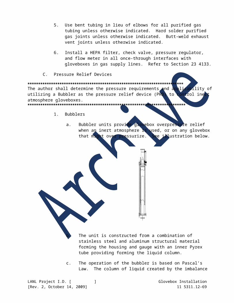
2. Stand Welds: Visually inspect welds performed during installation of the glovebox stand in accordance with requirements defined in AWS D1.1. Inspect welds from both sides, where feasible. Neither removal of the glovebox from the stand nor removal of legs from braces are required to inspect covered welds from the second side unless other indications are present that make the integrity of this weld suspect.
3. Repair welds not passing visual inspection using welding procedures defined in Section 11 5311.10.
D. Liquid Penetrant Examination
1. Confinement Welds: Liquid penetrant test all glovebox primary confinement welds performed during installation in accordance the liquid penetrant examination requirements identified in Section 11 5311.10. Mark all primary confinement welds performed during installation on the weld map supplied with the glovebox developed during glovebox fabrication.
2. Repair welds not passing liquid penetrant examination in accordance with requirements set forth in Section 11 5311.10.
E. Surface Finish Inspection
1. Verify surface finish of glovebox in accordance with requirements defined on Drawing 26Y-202001.
2. Perform visual and tactile inspection of the entire glovebox exterior and spot check of accessible interior areas paying particular attention to any burrs or sharp edges that could inadvertently damage a glove. Look especially for deep scratches caused by shipping or installation damage or by components shipped inside the glovebox breaking loose during transit.
3. Perform visual and tactile inspection of entire glovebox exterior and spot check of accessible interior areas paying particular attention to any areas of surface finish that may have decontamination concerns.
4. Perform surface finish inspection with a calibrated profilometer at several randomly selected areas on the interior and exterior of the glovebox. Include any suspect areas found above.
5. Repair damage to the glovebox surface finish in accordance with the requirements set forth in Section 11 5311.10.
F. Fastener Inspection
1. Stand-to-Stand Connections: Visually inspect all stand-to-stand (legs, braces, and top) connections to verify that all split lock washers are in place and crushed and that there are no visible gaps greater than 1/16-inch between adjacent structural members.
2. Stand-to-Glovebox Connections: Visually inspect all stand-to-glovebox connections to verify that all fasteners are in place. Verify by touch that no weld studs have been inadvertently broken by over tightening or shipping.
LANL Project I.D. [ ] Glovebox Installation[Rev. 2, October 14, 2009] 11 5311.12-69
3. Stand-to-Floor Connections: Shims – verify by visual inspection that any loose (non-welded) shims used between the facility floor and the glovebox stand do not exceed 1/4-inch. Verify installation of anchor bolts in accordance with manufacturer’s recommendations.
4. Window Clamp Strips: Visually inspect all bolted window clamp strip to glovebox connections to verify that all fasteners are in place. Verify by touch that no weld studs have been inadvertently broken by over tightening or shipping.
5. Miscellaneous: Visually inspect all other threaded mechanical connections to verify that all fasteners are in place. Verify by touch that no weld studs have been inadvertently broken by over tightening or shipping. Pay particular attention to joints that affect confinement such as flanges between gloveboxes, filter housing attachments, and bolted service panels.
6. Torque Map: Submit Torque Map identifying location of fastener, required torque, applied torque, and calibration data of torque wrench used to tighten fastener. Supply Torque Map for fasteners on windows, service panels, access panels, support stand anchors, support stand fasteners, and any other fastener with a specified torque in this specification.
The extent of piping examination, inspection and testing is defined in ASME B31.3. The scope of examination, inspection and testing is dependent upon the service category of the piping system (Normal Service Category, Category D, Category M, and High-Pressure Service Category). It is recommended that all piping systems transporting radioactive materials or have the potential of being contaminated with radioactive materials be categorized as Category M Services. Category M services are defined as piping systems transporting hazardous materials and typically require more stringent leak integrity. A helium leak test of piping systems can be substituted for the sensitive leak test requirements defined in ASME B31.3 provided that the helium leak rate is adequately defined.
G. Piping Examination, Inspection, and Testing
1. All Piping Service Categories:
a. Perform piping examination, inspection and testing in accordance with the specific piping service category [Normal Service Category, Category D, Category M, or High-Pressure Service Category] requirements of ASME B31.3.
b. Comply with methods for performing inspection, examination and testing as outlined in ASME B31.3, including but not limited to visual weld examination, and leak testing. Perform a pneumatic leak test in accordance with ASME B31.3 using design pressures for piping systems indicated above. Submit procedures to LANL for inspection, examination and testing defined in ASME B31.3.
c. Use testing personnel qualified in accordance with ASME B31.3. Use welding inspectors that have a current Certified Welding Inspector (CWI) certification in accordance with AWS QC-1 and ESM Chapter 13.
LANL Project I.D. [ ] Glovebox Installation[Rev. 2, October 14, 2009] 11 5311.12-70

d. Generate test records for examination, inspection and testing in accordance with ASME B31.3 and submit the test records to LANL for review and approval.
e. Use non-destructive examination (NDE) personnel certified per Level II or Level III of ASNT SNT-TC-1A. Submit NDE certifications for personnel performing NDE to LANL for review and approval. Sign test reports with Level II or Level III NDE personnel signatures that either performed or witnessed the test.
2. Category M Fluid Services
a. Develop and submit to LANL for review and approval procedures for performing examination, testing and inspection outlined in ASME B31.3 including, but not limited to, visual examination, visual weld examination, NDE, and leak testing.
b. Inspect, examine and test Category M service piping systems in accordance with the requirements set forth in ASME B31.3. Perform pneumatic leak tests and a sensitive leak test using design pressures indicated above.
Select welds to be radiographed following welding by the supplier. Where radiography and ultrasonic inspection is not practical the use of in-process inspection requires planning in the field to have the inspectors present during fabrication instead of after.
c. Perform random radiography of welds selected by LANL in accordance with ASME B31.3. In addition to the requirements in ASME B31.3, perform in-process examination of 20% of welded joints using personnel other than those performing the production work. Where radiography is not practical, use ultrasonic or in-process inspection of welds in accordance with ASME B31.3
d. Use testing personnel qualified in accordance with ASME B31.3. Use welding inspectors that have a current Certified Welding Inspector (CWI) certification in accordance with ESM Chapter 13 and AWS QC-1.
e. Generate test records for examination, inspection and testing in accordance with ASME B31.3 and submit the test records to LANL for review and approval.
f. Grind out and re-weld, using the original Welding Procedure Specification, welds not meeting the acceptance criteria for radiographic/ultrasonic examination as stated in ASME B31.3. Re-examine 100% of repaired welds in accordance with ASME B31.3. Do not repair welds more than twice before the section is abandoned and replaced.
g. Use non-destructive examination (NDE) personnel certified per Level II or Level III of ASNT SNT-TC-1A. Submit NDE certifications for personnel performing NDE to LANL for review and approval. Sign test
LANL Project I.D. [ ] Glovebox Installation[Rev. 2, October 14, 2009] 11 5311.12-71
reports with Level II or Level III NDE personnel signatures that either performed or witnessed the test.
H. Helium Leak Testing
1. Following installation and connection of the glovebox to existing facility systems, perform helium leak testing of the glovebox in accordance with the requirements in Section 11 5311.10.
2. Verify that all components of the glovebox system are installed prior to initiation of helium leak testing.
3. Isolate the glovebox from adjacent systems as required to contain the helium test gas. This may include blanking off the exhaust filter outlet, air inlets, and other openings.
I. Continuity Check
1. Following all wiring and labeling activities, perform electrical continuity testing. Use a battery-powered buzzer or ohmmeter to determine that all power, control, instrumentation, and grounding, circuits are complete and properly identified. Verify that the resistance between the main ground connection and the glovebox support stand and any point in the ground circuit is less than 0.1 ohms. Verify instrument ground is separate and isolated from the power ground circuit and that no unintentional electrical grounds exist. Prepare a log of circuits tested and submit the log to LANL for review and approval.
J. Checklist
1. Complete the Glovebox Certification Checklist provided in Attachment 1 prior to use of the glovebox.
END OF SECTION
******************************************************************************Do not delete the following reference information.******************************************************************************
FOR LANL USE ONLY
This project specification is based on LANL Master Specification 11 5311.12 Rev. 2 dated October 14, 2009.
LANL Project I.D. [ ] Glovebox Installation[Rev. 2, October 14, 2009] 11 5311.12-72
Section 11 5311.12 - Attachment 1Glovebox Installation Checklist
Using Group: ____________________ DCP No: ____________________
Glovebox ID: ____________________ Glovebox Location: ____________________
Date of General Walkthrough: __________ Date of Final Walkthrough: __________
Sheet 1 of ___
No. Finding CommentY/N
Final Finding
Glovebox Requirement
1.0 Electrical Services1.1 Circuits are properly identified at penetrations
1.2 Circuits are properly identified at breaker panels
1.3 Voltage and wiring has been checked
1.4 Instrumentation receptacles and cables identified
1.5 Instrument passthroughs are site or factory tested and properly installed
1.6 Photohelic and solenoid wiring has been checked
1.7 Glovebox frame properly grounded
1.8 Other
2.0 Fire Safety
2.1Heat sensors are connected. Operability test must be performed in accordance with NMT8-ASI-007-R02
2.2 Fire screens protect the HEPA filters
2.3 Combustible loading is acceptable
2.4 Gloves are protected from hot equipment or operations
2.5 Equipment cooling water circuits have over-temperature and loss of flow interlocks
2.6 Other
3.0 Seismic Safety3.1 Enclosure support properly attached to the floor
3.2 Heavy objects on top of or inside enclosure properly secured
4.0 Glovebox Integrity
4.1
Enclosure interior meets surface finish and flatness requirements as defined on Drawing 26Y-202001. Verify flatness around openings prior to installation and following any welding performed on glovebox shell during installation.
4.2 Fabricator certified that enclosure is helium leak-tight (new installations only)
4.3 Helium leak test performed after enclosure installed (new or cold installations only)
LANL Project I.D. [ ] Glovebox Installation[Rev. 2, October 14, 2009] 11 5311.12-73
Glovebox Certification Checklist, (Continued)
Sheet 2 of ___ Glovebox ID: ____________________ DCP No: _____________
No. Finding CommentY/N
Final Finding
Glovebox Requirement
4.0 Glovebox Integrity (Continued)
4.4 Service panels, filter hat and flanged penetrations have approved gaskets
4.5
Window frame bolts have been torqued (25 5 in-lb) and gasket surfaces appear smooth. Supply Torque Map to document fastener torques.
4.6 Zipper window gaskets have proper zippers
4.7 Unused penetrations plugged inside and outside
4.8 Gloves are properly attached to glove rings
4.9 HEPA filters to Zone 1 exhaust have been properly installed and successfully leak tested
4.10 Hoods have the required face velocity (HSR certified)
4.11Enclosure pressure gauges (Magnehelic or Photohelic) are active and respond to changes in pressure
4.12Enclosure pressure gauges (Magnehelic and Photohelic) have been “zeroed” and accurately reflect pressure in the enclosure
4.13 Other
5.0 Mechanical Services5.1 All gas and liquid services are labeled
5.2 Industrial water piped into enclosure has “dead-man” valves to prevent flooding
5.3Gas service lines to enclosures are 3/8-in. or smaller except with special approval (Note: ¼-in. or smaller for helium)
5.4 No positive pressure cooling water, except for limited volume systems, is piped into enclosures
5.5 Positive pressure chilled circulating water is used to cool equipment exterior to the enclosure
5.6 Chilled or heated piping is properly insulated
5.7 House and wet vacuum lines are trapped to prevent flooding of lines or enclosures
5.8
All gas supplies entering gloveboxes have pressure regulating valves, check valves, gauges near work stations, properly sized orifices in services above 25 psig, and high flow, in-line filters
5.9All pressure regulating valves (PRV) for gas services are set for 25 psig maximum (except for instrument air, or by special approval)
LANL Project I.D. [ ] Glovebox Installation[Rev. 2, October 14, 2009] 11 5311.12-74
Glovebox Certification Checklist, (Continued)
Sheet 3 of ___ Glovebox ID: ____________________ DCP No: ___________________No. Finding Comment
Y/NFinal
FindingGlovebox Requirement
5.0 Mechanical Services (Continued)
5.10 At least one gauge is provided downstream of all PRVs to verify indications of the PRV gauges
5.11 Glovebox service lines have been traced to facility service lines to verify labeling
5.12 Flanges of wet vacuum and liquid-carrying lines are plastic-wrapped
5.13Supply lines for air-driven stirrers, vibrators, pumps, etc., inside gloveboxes have solenoid valves interlocked to glovebox pressure
5.14 Air-operated cylinders have PRVs and flow-regulating valves
5.15Air-operated cylinders with shafts penetrating contaminated enclosures have HEPA filters and exhaust to Zone 1 ductwork
5.16
Vacuum pumps have metal piping to enclosures, have an intake HEPA filter (in accordance with Section 23 4133) between the vacuum pump and enclosure, and exhaust through metal piping to the Zone 1 system
5.17 HEPA filter housings (meeting the requirements of Section 23 4133) appear in good condition
5.18Pressurized piping, vessels, columns, etc., have been evaluated and leak tested for operating pressures
5.19 Other
6.0 Special Items for Inert Atmosphere Enclosures
6.1 The damper in the Zone 1 exhaust line is locked in the full open position
6.2 Pressure relief devices (bubblers) are filled with approved fluid to the proper level
6.3 Bubbler bypass piping is installed per repeatable detail with manual and solenoid valves
6.4The enclosure, airlock, and connecting piping have been helium leak checked after installation (new and cold installations only)
6.5Recirculating purifiers (Dri-Trains) have HEPA filters, PRVs and flow meters (where required) in gas supply lines
LANL Project I.D. [ ] Glovebox Installation[Rev. 2, October 14, 2009] 11 5311.12-75
Glovebox Certification Checklist, (Continued)
Sheet 4 of ___ Glovebox ID: ____________________ DCP No: ___________________
No. Finding CommentY/N
Final Finding
Glovebox Requirement
6.0 Special Items for Inert Atmosphere Enclosures (continued)
6.6
Dri-Train recirculating lines are hard soldered and equipped with high vacuum shut-off valves and inlet and outlet HEPA filters inside the enclosure
6.7 Dri-Train vacuum pumps have approved filters and exhaust into the Zone 1 system
6.8 Dri-Trains are of the type approved for PF-4 service
6.9 Other
7.0 Radiation and Criticality Safety
7.1Criticality assessment has been performed and approved criticality limits have been posted and pegboards are in place
7.2 Hand monitors are in place near work stations
7.3 Fixed head air samplers are properly mounted on the enclosures
7.4 CAM air sample tubes are in place at hood faces
7.5 Hand and foot monitors are available in the working area
7.6 MASS System and enclosure numbers are posted
7.7 Radiation shield is adequate for the operation
7.8 Other
8.0 Maintenance Access
8.1 Glovebox fitted for safety railing on top and ladders on side
8.2 Glovebox top windows and lights are protected from weight and impact.
8.3 Other
9.0 Glovebox Glove Sharps (Ref. Lessons Learned # 2009-26)
9.1 Area around glovebox gloves is clear of pinchpoints or unplanned contact with equipment
9.2 Equipment inside glovebox free from sharpcorners, sharp edges, and abrasive surfaces
9.3 Threaded fasteners inside glovebox do not havemore than 1 to 2 exposed threads
9.4 Other
10.0 Summary Certification Finding10.1 New glovebox installation
10.2 Modified glovebox installation
LANL Project I.D. [ ] Glovebox Installation[Rev. 2, October 14, 2009] 11 5311.12-76
Glovebox Certification Checklist, (Continued)
Sheet 5 of ___ Glovebox ID: ____________________ DCP No: ______________
COMMENTS AND EXPLANATIONS:
________________________________________________________________________________________________________________________________________________________________________________________________________________________________________________________________________________________________________________________________________________________________________________________________________________________________________________________________________________________________________________________________________________________________________________________________________________________________________________________________
Connection to Zone 1 (not for normal operations) is authorized:
Glovebox System Engineer Date
Glovebox meets facility requirements for normal operations
Glovebox System Engineer Date
-INSTRUCTIONS & ABBREVIATIONS-
Certification that gloveboxes, hoods, equipment, and mechanical and electrical services meet LANL TA-55 standards will be done by qualified personnel.
Inspections may be performed by individuals alone or by teams of qualified individuals. Inspections should be performed during appropriate phases of construction to avoid costly changes after construction is completed.
Findings may be:
“Conforming” (C), “Not Applicable” (NA), “Nonconforming - OK” (NC-OK), “Nonconforming - Must Correct” (NC-MC), or “Pending certification after connection to Zone 1” (P)
All findings, except “C”, must be addressed in the “Comments and Explanations.
LANL Project I.D. [ ] Glovebox Installation[Rev. 2, October 14, 2009] 11 5311.12-77