Section 1 Overview - Mr. Marshallsay's Physics Site -...
50
Physics Problems - Practical Electronics 1 Section 1 Overview Electronic components are used many appliances. Can you find ten appliances in the wordsearch below. E E M T V Y S A A R Y F M N R N S Q R T D Y D R P E H R A E I T E T E A R N V N Y E F C D H E S V L Y Z L H V T I R N R C R A B E K G C G U R K Y O O A E T N P Y T W P E I G A I C M O E L H N U M A L N C R S E G S L M O X O L S H O B E I R N Y L X N C A T G C M M M V O I S I Q E R F F V M N S A E E H T T L M Q Q L Q H X X C L D S E E H J O X D F E N T V E I A M A G T H E G D I R F K T V W
Transcript of Section 1 Overview - Mr. Marshallsay's Physics Site -...

Physics Problems - Practical Electronics
1
Section 1 Overview
Electronic components are used many appliances. Can you find ten appliances in the
wordsearch below.
E E M T V Y S A A R Y F M N
R N S Q R T D Y D R P E H R
A E I T E T E A R N V N Y E
F C D H E S V L Y Z L H V T
I R N R C R A B E K G C G U
R K Y O O A E T N P Y T W P
E I G A I C M O E L H N U M
A L N C R S E G S L M O X O
L S H O B E I R N Y L X N C
A T G C M M M V O I S I Q E
R F F V M N S A E E H T T L
M Q Q L Q H X X C L D S E E
H J O X D F E N T V E I A M
A G T H E G D I R F K T V W

Physics Problems - Practical Electronics
2
Section 2 - Output Devices
Identifying Output Devices
1. Which of the components in the list below are output devices?
bulb thermistor relay thermocouple solenoid loudspeaker
dynamo LED LDR buzzer motor microphone
2. Which output device could be used in a central locking system of a car?
3. What would be an appropriate output device for a public address system?
4. Select an output device which could be used to raise and lower blinds automatically in
a luxury flat.
5. Which output device is useful for digital displays on hi-fi systems?
The Light Emitting Diode (LED)
1. Which of the following LED’s will light?
A
F
E D C
B

Physics Problems - Practical Electronics
3
When working with LED circuits you can use the equation:
Helpful Hint
When applying this equation remember that the supply voltage is shared between the
LED and the resistor.
Example
A certain LED takes a current of 10 mA and the voltage across it is 2 V. What should be
the value of the series resistor when a supply voltage of 5 V is used?
1st. Sketch the circuit 2nd. Calculate the voltage across resistor R.
2. Use the stages outlined above to find the missing values in the following table.
Vsupply
Vsupply (V) Voltage across
LED (V)
Current (A) Voltage across
R (V)
Resistance of R
()
(a) 6 2·0 0·010
(b) 12 2·0 0·010
(c) 8 1·8 0·016
(d) 20 1·6 0·008
(e) 4 1·5 0·020
(f) 11 2·0 0·012
5 V VR = Vsupply - Vled
= 5 - 2
= 3 V I = 10 mA
= 0·010
A R
2V
R
VR
I
Vled
V = IR
3rd. Apply V = IR to find the value of R
VR = 3 V VR = I R
I = 0·01 A 3 = 0·01 x R
R = ? R = 3 / 0·01
R = 300
Physics Problems - Practical Electronics
4
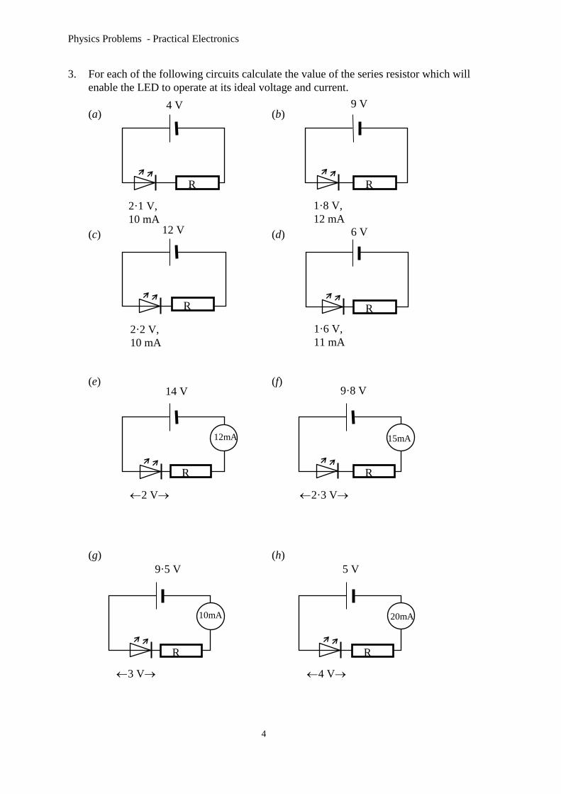
6 V
1·6 V,
11 mA
3. For each of the following circuits calculate the value of the series resistor which will
enable the LED to operate at its ideal voltage and current.
(a) (b)
(c) (d)
(e) (f)
(g) (h)
4 V
2·1 V,
10 mA
9 V
1·8 V,
12 mA
9·8 V
2·3 V
9·5 V
3 V
14 V
2 V
12 V
2·2 V,
10 mA
5 V
4 V
R R
R R
12mA 15mA
R R
R R
10mA 20mA

Physics Problems - Practical Electronics
5
5·1 V
400
800
2·2 V,
11 mA
4. Consider the following circuit.
(a) Calculate the voltage across the 400 resistor.
(b) Calculate the voltage across the LED.
5. For the circuit shown below work out the value of the supply voltage which will
enable the LED to operate at it’s stated rating.
6. The voltage and current specifications for a certain LED are 1·75 V and 10 mA
respectively. What should be the value of the series resistor if the LED is powered by
a 6 V supply?
7. Calculate the ammeter reading in the following circuit.
8. Calculate the voltmeter reading in the circuit shown below.
8mA
12 V
1·8 V 2 040
6 V
475
A
V
8mA

Physics Problems - Practical Electronics
6
9. What is the supply voltage for the following circuit?
10. Calculate the value of resistor R in the circuit below.
1 200
3V
9 V
R
15mA
20mA
4V

Physics Problems - Practical Electronics
7
Binary to Decimal Conversion
Helpful Hint
Digital systems use binary because this can be represented by a series of 1’s and 0’s
unlike decimal which requires the numbers 1,2,3,4,5,6,7,8& 9.
Numbers in binary are made up in the same way as numbers in decimal.
For example consider the number 6752. The position of each number gives its value.
1000 100 10 1
6 7 5 2
6752 means 6 thousands 7 hundreds 5 tens 2 units
The position of each number in binary also gives its value.
Consider the binary number 1111
8 4 2 1
1 1 1 1
1111 means 1 eight 1 four 1 two 1 one
We can convert this to a decimal number by simply adding up the numbers.
8 + 4 + 2 + 1 = 15
so 1111 in binary is 15 in decimal
1. Convert each of the following binary numbers into a decimal number:
(a) 0101 (b) 1001 (c) 1010 (d) 0110
(e) 1101 (f) 1011 (g) 0111 (h) 1000
2. In an electronic counter the output is a binary number represented by a series of Light
Emitting Diodes.
ON OFF ON OFF
The decoder chip converts the binary number into a decimal number which is
displayed on a seven segment display.
For each of the following binary outputs give the decimal number which would
appear on the seven segment display.
(a) (d)
(b) (e)
(c) (f)

Physics Problems - Practical Electronics
8
Section 3 - Input Devices
In this section you can use the equation:
where V = voltage in volts (V)
I = current in amps (A)
R = resistance in ohms ( ).
Helpful Hint
When choosing an input device for an electronic system, think about what type of
energy the device has to detect.
Capacitor microphone thermistor solar cell
light dependent resistor (LDR) thermocouple
1. Select from the list above a suitable input device for each of the following:
(a) Public address system in a railway station
(b) Digital thermometer
(c) Photographers light meter
(d) Time delay circuit for courtesy lights in a car
(e) Pilot light flame detector in a gas central heating system
(f) Sunlight hours recorder at a weather station.
2. The circuits below show two identical LDR’s each connected to a 6 V supply.
One LDR is placed in a cupboard and the other is placed beside a window.
Circuit (i) Circuit (ii)
(a) Calculate the resistance of each LDR.
(b) Which circuit shows the LDR in the cupboard?
6 V 6 V
0·03 A 0·002 4 A
V = IR

Physics Problems - Practical Electronics
9
3. The following circuit shows a thermistor connected to a 5 V supply and placed in a
school laboratory.
In the morning the ammeter gave a reading of 1·25 mA. Later in the same day the
reading had risen to 2·5 mA.
(a) Calculate the resistance of the thermistor in the morning.
(b) What happened to the temperature in the room during the day?
Explain your answer.
4. The following information for an LDR was found in a components catalogue.
Light Source Illumination (lux) Resistance (k)
moonlight 0·1 10 000
60 W bulb at 1m 50 2·4
fluorescent light 500 0·2
bright sunlight 30 000 0·02
This LDR is connected to a 12 V supply with an ammeter in series with it as shown in
the diagram.
(a) What is the resistance in ohms of the LDR when exposed to fluorescent light?
(b) What would the ammeter read when a lamp with a 60 W bulb in it is placed 1 m
away from the LDR?
(c) When the ammeter gives a reading of 0·6 A which light source is being used?
5 V
A
A
12 V

Physics Problems - Practical Electronics
10
5. A pupil uses a thermistor as a simple electronic thermometer. She connects the
thermistor to an ammeter and places the thermistor into a beaker of hot water. The
ammeter gives a reading of 8 mA.
Temperature (oC) Resistance ()
20 3 750
40 198
60 750
80 350
100 200
(a) What is the temperature of the water in the beaker?
(b) The pupil adds some more water to the beaker and the ammeter gives a new
reading of 1·6 mA. Did the pupil add hot or cold water to the beaker?
(c) What is the new temperature of the water?
(d) What will the ammeter read when the water is boiling?
A
6 V
Physics Problems - Practical Electronics
11
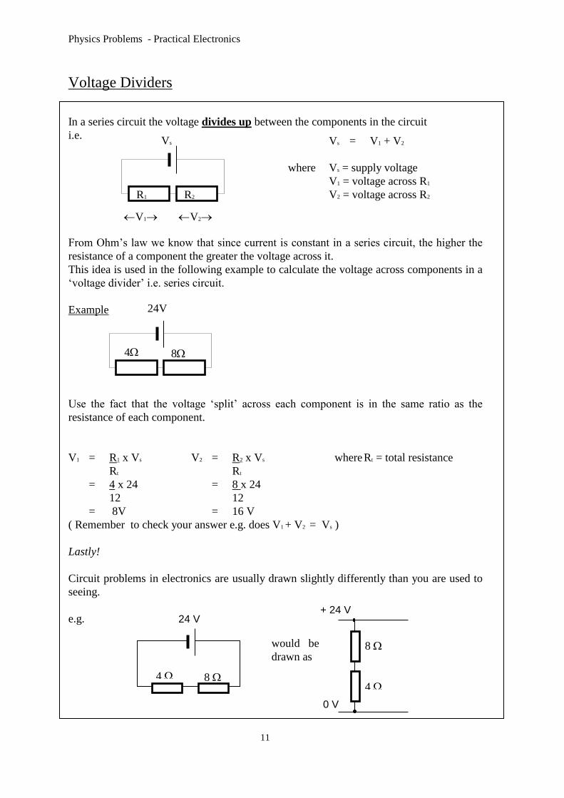
Voltage Dividers
In a series circuit the voltage divides up between the components in the circuit
i.e.
From Ohm’s law we know that since current is constant in a series circuit, the higher the
resistance of a component the greater the voltage across it.
This idea is used in the following example to calculate the voltage across components in a
‘voltage divider’ i.e. series circuit.
Example
Use the fact that the voltage ‘split’ across each component is in the same ratio as the
resistance of each component.
V1 = R1 x Vs V2 = R2 x Vs where Rt = total resistance
Rt Rt
= 4 x 24 = 8 x 24
12 12
= 8V = 16 V
( Remember to check your answer e.g. does V1 + V2 = Vs )
Lastly!
Circuit problems in electronics are usually drawn slightly differently than you are used to
seeing.
e.g.
V1 V2
R1 R2
Vs Vs = V1 + V2
where Vs = supply voltage
V1 = voltage across R1
V2 = voltage across R2
4 8
24V
24 V
4 8
would be
drawn as
+ 24 V
0 V
8
4

Physics Problems - Practical Electronics
12
Find the voltage across each resistor in the following:
(1) (2) (3)
(4) (5) (6)
(7) (8) (9)
(10) (11) (12)
+ 12 V
0 V
10
10
+ 12 V
0 V
10
2
+ 24 V
0 V
6
6
+ 10 V
0 V
6
4
+36 V
0 V
16
20
+ 24 V
0 V
5
10
+ 36 V
0 V
3
9
+ 24 V
0 V
4
8
+ 36 V
0 V
4
12
3
3
+ 24 V
0 V
18
36
+36 V
0 V
7
21
+ 36 V
0 V

Physics Problems - Practical Electronics
13
(13) (14) (15)
(16) (17) (18)
(19) (20)
+ 5 V
0 V
3 k
2 k
+ 240 V
0 V
434
62
+ 36 V
0 V
25
15
+ 20 V
0 V
100
22
+ 24 V
0 V
180
36
+ 12 V
0 V
3
6
+ 10 V
0 V
120
40
+ 240 V
0 V
144
36

Physics Problems - Practical Electronics
14
LDR
Light condition Resistance ()
dark 10 000
light 2 500
bright 20
Thermistor
Temperature (o C) Resistance ()
10 4 000
40 1 980
100 200
The following tables indicate how the resistance of an LDR and thermistor vary with
external conditions.
Use the information above to solve questions 21 - 24.
21. The following circuit is part of the input to an electronic frost alarm.
If the circuit operates from mains voltage
calculate the voltage drop across the
thermistor when it is
(a) 10 o C
(b) 40 o C
22. The following circuit could be part of a light meter for a camera.
Use the information above to find the voltage
drop across the LDR when it is:
(a) dark
(b) light
+ 230 V
0 V
100
+ 12 V
0 V
1 k
Helpful Hint
LDR’s and thermistors often make up part of a voltage divider circuit in electronic systems.
It is important to remember that the resistance of these components varies with external
conditions.

Physics Problems - Practical Electronics
15
23. Calculate the voltage across the resistor in the following circuit when the temperature
is:
(a) 100 o C
(b) 40 o C
24. A young engineer designs part of an electronic system to trigger an alarm when it gets
too bright.
What will the ‘trigger voltage’ across the resistor be in the following system when it is
‘bright’?
25. At what temperature would the following circuit show equal readings on each
voltmeter?
+ 24 V
0 V
500
+ 36 V
0 V
1·5k
+ 230 V
0 V
200
V1
V2

Physics Problems - Practical Electronics
16
Calculate the voltage at X in questions 26 - 30.
26. 27. 28.
Switch S open Capacitor C uncharged Switch S closed
29. 30.
Capacitor C fully charged Switch S open.
Helpful Hint
In a circuit like the following:
You are often required to calculate the voltage( or potential) at X
This is the same as asking for the voltage (or potential) across resistor R2
X
+ 5 V
0 V
R1
R2
X
+ 12 V
0 V
20
X
+12 V
0 V
10 k
X
+ 5 V
0 V
3·5 k
X
+ 36 V
0 V
1 k
X
+ 5 V
0 V
65

Physics Problems - Practical Electronics
17
Section 4 - Digital Processes
Transistors in Circuits
Helpful Hint
The symbol for an NPN transistor is shown below.
The transistor operates as a switch in a circuit. It switches ‘ON’ when the voltage
across XY, in the diagram below, is above approximately 0·7 V.
In the last section you studied voltage dividers. A voltage divider is usually
placed between P and Q. Various components can be used to make up the
voltage divider but it is always the voltage across XY which affects the
transistor!
Some examples are shown on the next page.
P
Q
X
Y
0·7 V
Physics Problems - Practical Electronics
18
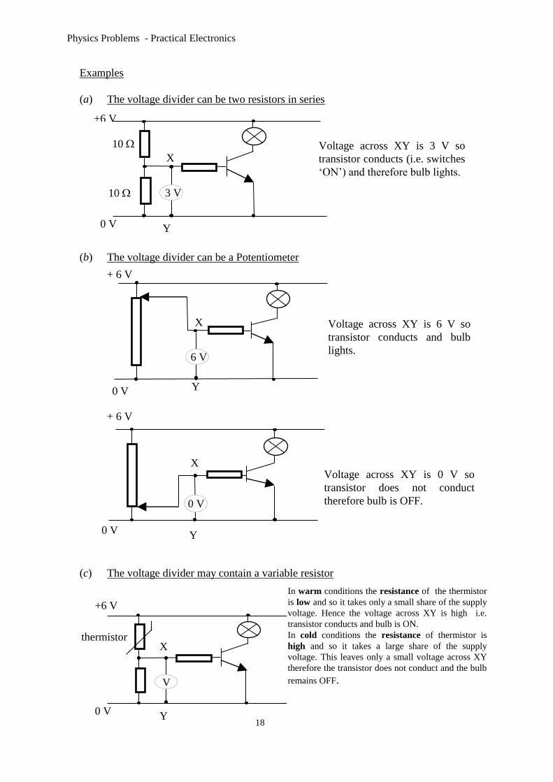
Examples
(a) The voltage divider can be two resistors in series
(b) The voltage divider can be a Potentiometer
(c) The voltage divider may contain a variable resistor
+6 V
0 V Y
V
thermistor
In warm conditions the resistance of the thermistor
is low and so it takes only a small share of the supply
voltage. Hence the voltage across XY is high i.e.
transistor conducts and bulb is ON.
In cold conditions the resistance of thermistor is
high and so it takes a large share of the supply
voltage. This leaves only a small voltage across XY
therefore the transistor does not conduct and the bulb
remains OFF.
X
Voltage across XY is 3 V so
transistor conducts (i.e. switches
‘ON’) and therefore bulb lights.
6 V
+ 6 V
X
Y 0 V
Voltage across XY is 6 V so
transistor conducts and bulb
lights.
0 V
Voltage across XY is 0 V so
transistor does not conduct
therefore bulb is OFF.
X
10
10
+6 V
0 V Y
3 V
+ 6 V
X
Y 0 V
Physics Problems - Practical Electronics
19
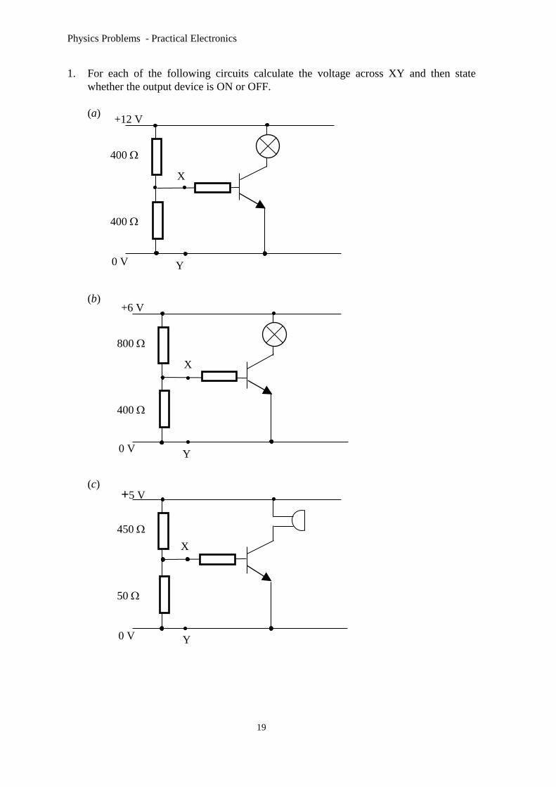
1. For each of the following circuits calculate the voltage across XY and then state
whether the output device is ON or OFF.
(a)
(b)
(c)
X
450
50
Y
X
400
400
+5 V
0 V
+12 V
0 V Y
X
800
400
+6 V
0 V Y

Physics Problems - Practical Electronics
20
(d)
(e)
(f) (Hint! Think here!)
X
10
80
+4 V
0 V Y
X
100
400
Y
X
100
3·9 k
+2 V
0 V Y
+1·5 V
0 V
Physics Problems - Practical Electronics
21
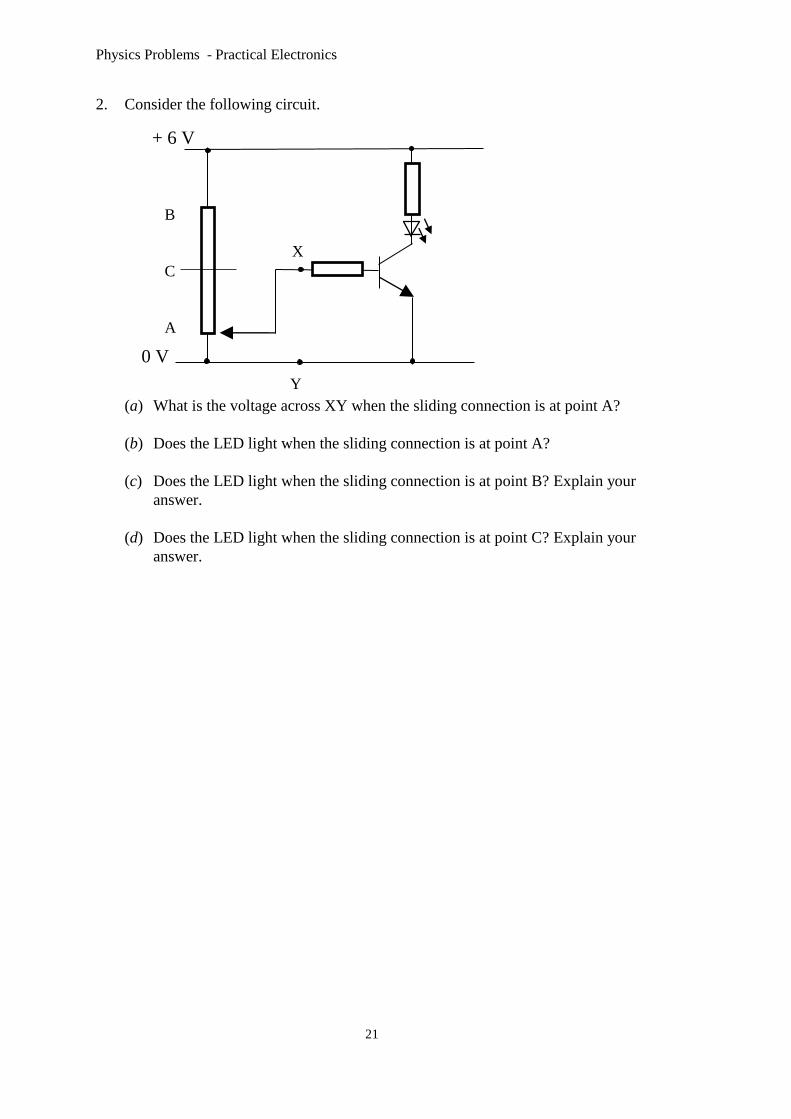
2. Consider the following circuit.
(a) What is the voltage across XY when the sliding connection is at point A?
(b) Does the LED light when the sliding connection is at point A?
(c) Does the LED light when the sliding connection is at point B? Explain your
answer.
(d) Does the LED light when the sliding connection is at point C? Explain your
answer.
+ 6 V
X
Y
0 V
B
C
A
Physics Problems - Practical Electronics
22
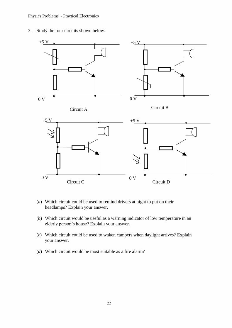
3. Study the four circuits shown below.
(a) Which circuit could be used to remind drivers at night to put on their
headlamps? Explain your answer.
(b) Which circuit would be useful as a warning indicator of low temperature in an
elderly person’s house? Explain your answer.
(c) Which circuit could be used to waken campers when daylight arrives? Explain
your answer.
(d) Which circuit would be most suitable as a fire alarm?
+5 V
0 V
+5 V
0 V
+5 V
0 V
+5 V
0 V
Circuit A Circuit B
Circuit C Circuit D

Physics Problems - Practical Electronics
23
4. The following circuit is used to switch on an electric heater automatically when the
temperature in a room falls below a certain value.
(a) Explain how the circuit operates.
(b) What would be the effect of decreasing the resistance of the variable resistor?
(c) Why would it be unsuitable to put the heater at point X instead of the relay?
5. For each of the following circuits state whether the output device is ON or OFF and
explain your answer.
(a) (b)
(c) (d)
+ 5 V
mains 230 V
0 V
heater
X
+5 V
0 V
+5 V
0 V
+5 V
0 V
+5 V
0 V
capacitor
uncharged capacitor
charged

Physics Problems - Practical Electronics
24
(e) (f)
+5 V
0 V
+5 V
0 V
capacitor
charged
switch
closed

Physics Problems - Practical Electronics
25
Logic Gates
1. Identify the logic gate represented by each of the following truth tables.
(a)
Input Output
0 1
1 0
(b) (c)
Input 1 Input 2 Output Input 1 Input 2 Output
0 0 0 0 0 0
0 1 1 0 1 0
1 0 1 1 0 0
1 1 1 1 1 1
2. For each of the following combinations of logic gates complete a truth table of the
form:
Input A Input B Output
0 0
0 1
1 0
1 1
(a) (b)
(c) (d)
(e)
A
B
A
B
A
B A
B
A
B

Physics Problems - Practical Electronics
26
(f )
3. Each of the following combinations of logic gates has three inputs. For each
combination complete a truth table of the form:
Input A Input B Input C Output
0 0 0
0 0 1
0 1 0
0 1 1
1 0 0
1 0 1
1 1 0
1 1 1
(a) (b)
(c) (d)
(e) (f)
A
B
A
B
A
B
C
A
B
C
A
B
C
A
B
C C
A
B
C

Physics Problems - Practical Electronics
27
(g)
4. Each of the following combinations of logic gates involve linked inputs, that is two
inputs being fed into different gates. For each combination complete a truth table of
the form:
Input A Input B Output
0 0
0 1
1 0
1 1
(a) (b)
(c) (d)
5. Show the pattern of pulses that would appear at the output of each of the following
gates as a result of the input pulses shown.
(a) (b)
(c) (d)
A
B
C
A
B
A
B A
B
A
B
Physics Problems - Practical Electronics
28
Section 5 - Analogue Processes
Devices containing amplifiers
(1) In which of the following systems do amplifiers play an important part?
radio capacitor TV loudspeaker LED solenoid
stereo remote control car public address system.
Voltage Gain
In this section you can use the equation:
also written as:
where Vout = Output voltage in volts (V)
Vin = Input voltage in volts (V).
(Note: Voltage gain has no unit since it is a ratio of input to output voltages.)
1. Find the missing values in the following table.
Input voltage (V) Output voltage (V) Voltage Gain
(a) 2 10
(b) 24 96
(c) 3 10
(d) 15 5
(e) 100 20
(f) 16 2
2. Calculate the gain of a guitar amplifier if the input signal is 2·3 V and the output
signal is 46 V.
output voltage
input voltage voltage gain =
voltage gain = Vout
Vin

Physics Problems - Practical Electronics
29
3. A student studies the input and output traces from an amplifier and displays the
results on an oscilloscope.
Use the trace to find the gain of the amplifier.
4. A hearing aid amplifies an input signal by a factor of 20. What would be the voltage
of an output signal if the input signal was 0·12 V?
5. Televisions use amplifiers to boost the signal received after transmission. The output
voltage of an amplifier is 2·3 mV and its gain is 15. Calculate the size of the input
voltage collected at the aerial.
6. A pick up cartridge can produce a 0·2 mV signal which is then amplified. What is the
gain of an amplifier which increases this signal to 15 V?
7. If the voltage gain of a pre-amp is 4 000 and the input signal is 3 mV, calculate the
output voltage.
8. A signal generator connected to a loudspeaker is used to investigate the range of
human hearing. The output from the loudspeaker is 20 V and the gain is 1 000.
Calculate the size of the input signal.
9. A CD sends signals of approximately 0·25 mV to a pre-amplifier which produces an
output voltage of 15 V. Use this data to find the gain of the pre-amplifier.
10. Calculate the output voltage of a personal stereo amplifier if it has a gain of 2 500 and
the input voltage is 3·5 mV.
0 V
6 V
0 V
12 V
Input signal Output signal

Physics Problems - Practical Electronics
30
Power Gain
In this section you can use the equation:
also written as:
where Pout = Output power in Watts (W)
Pin = Input power in Watts (W).
(Note: Power gain has no unit since it is a ratio of input to output powers.)
1. Find the missing values in the following table:
Input Power (W) Output Power (W) Power Gain
(a) 0·006 60
(b) 40 5 000
(c) 4 x 10⁻³ 80
(d) 50 100
(e) 0·002 3 000
(f) 5 x 10⁻³ 200
2. An amplifier delivers an output of 60 W when the input power is 1·8 W. What is the
power gain of the amplifier?
3. What would be the input power to an amplifier with a power gain of 400, if it delivers
an output of 40 W?
4. The signal from a compact disc player has a power of 6 mW. The attached amplifier
has a gain of 5 000. What is the power delivered to the speaker?
output power
input power power gain =
power gain = Pout
Pin
Physics Problems - Practical Electronics
31
Helpful Hint
In this section you can also use the equation
where P= power in watts (W)
V= voltage in volts (V)
R= resistance in ohms ().
5. Find the missing values in the following table:
Power (W) Voltage (V) Resistance ()
(a) 9 16·2
(b) 20 100
(c) 3 000 230
(d) 4·8 6
(e) 3 48
(f) 48 1 200
6. An amplifier is fed with an input voltage of 12 mV. Calculate the input power of the
amplifier given that the input resistance is 15 k.
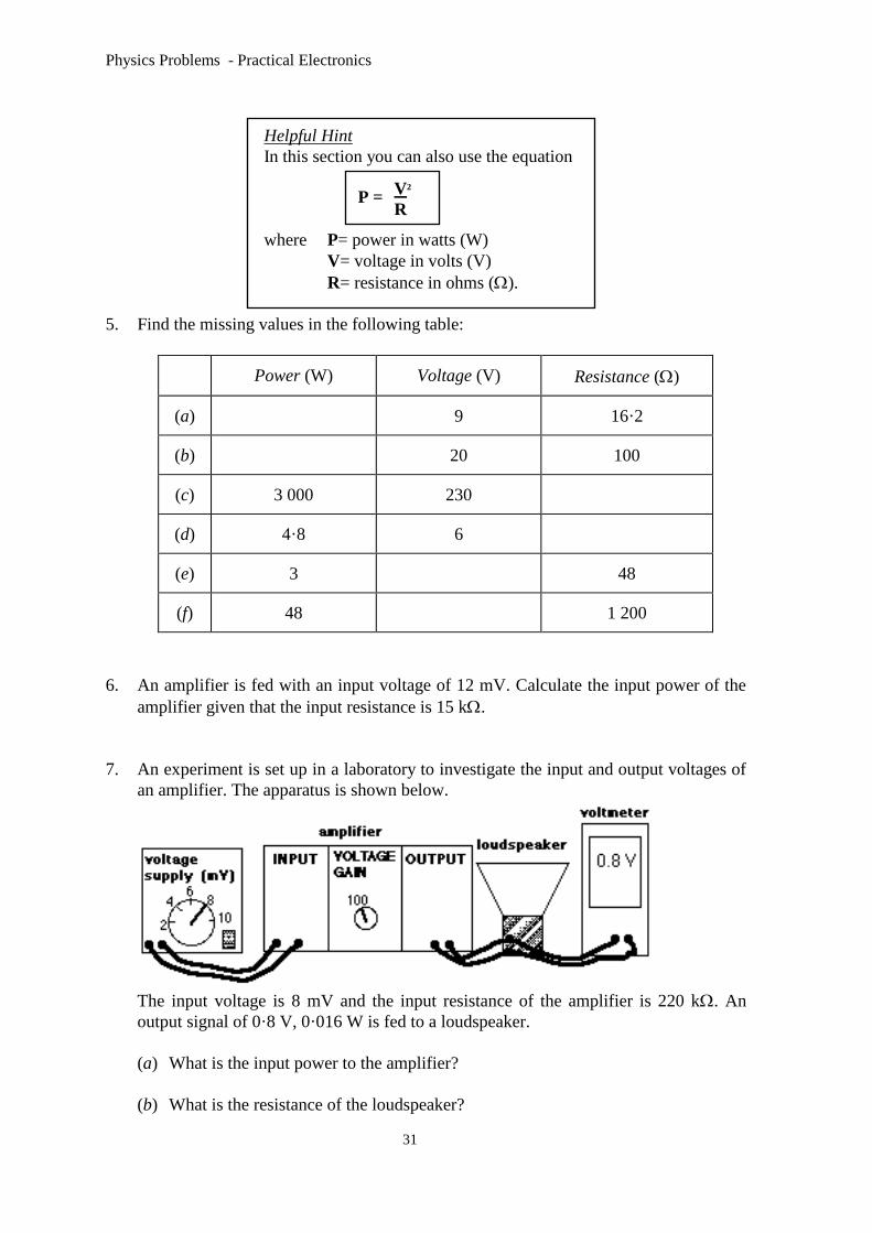
7. An experiment is set up in a laboratory to investigate the input and output voltages of
an amplifier. The apparatus is shown below.
The input voltage is 8 mV and the input resistance of the amplifier is 220 k. An
output signal of 0·8 V, 0·016 W is fed to a loudspeaker.
(a) What is the input power to the amplifier?
(b) What is the resistance of the loudspeaker?
P =
V2
R
Physics Problems - Practical Electronics
32
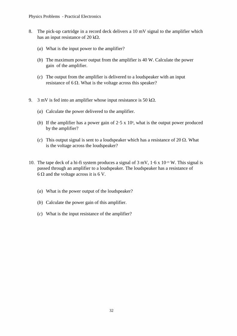
8. The pick-up cartridge in a record deck delivers a 10 mV signal to the amplifier which
has an input resistance of 20 k.
(a) What is the input power to the amplifier?
(b) The maximum power output from the amplifier is 40 W. Calculate the power
gain of the amplifier.
(c) The output from the amplifier is delivered to a loudspeaker with an input
resistance of 6 . What is the voltage across this speaker?
9. 3 mV is fed into an amplifier whose input resistance is 50 k.
(a) Calculate the power delivered to the amplifier.
(b) If the amplifier has a power gain of 2·5 x 109, what is the output power produced
by the amplifier?
(c) This output signal is sent to a loudspeaker which has a resistance of 20 . What
is the voltage across the loudspeaker?
10. The tape deck of a hi-fi system produces a signal of 3 mV, 1·6 x 10-10 W. This signal is
passed through an amplifier to a loudspeaker. The loudspeaker has a resistance of
6 and the voltage across it is 6 V.
(a) What is the power output of the loudspeaker?
(b) Calculate the power gain of this amplifier.
(c) What is the input resistance of the amplifier?
Physics Problems - Practical Electronics
33
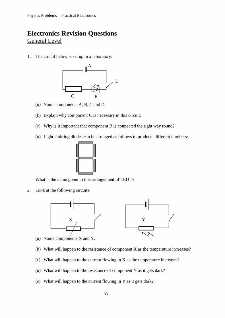
Electronics Revision Questions General Level
1. The circuit below is set up in a laboratory.
(a) Name components A, B, C and D.
(b) Explain why component C is necessary in this circuit.
(c) Why is it important that component B is connected the right way round?
(d) Light emitting diodes can be arranged as follows to produce different numbers:
What is the name given to this arrangement of LED’s?
2. Look at the following circuits:
(a) Name components X and Y.
(b) What will happen to the resistance of component X as the temperature increases?
(c) What will happen to the current flowing in X as the temperature increases?
(d) What will happen to the resistance of component Y as it gets dark?
(e) What will happen to the current flowing in Y as it gets dark?
C
A
D
Y
B
X

Physics Problems - Practical Electronics
34
3. The resistance of a certain thermistor was recorded at various temperatures. The
results are shown in the table below.
Temperature (oC) Resistance ( )
10 4 000
40 1 980
100 200
The thermistor was then connected to a 4 V battery and ammeter and exposed to the
same range of temperatures
(a) What was the ammeter reading when the temperature was 10 0C?
(b) What temperature is indicated by an ammeter reading of 0·02 A?
4. Look at the following electronic symbols.
(a) Name the device represented by each symbol.
(b) Which device can be used as a switch?
(c) Which device is represented by the following truth table?
A B output
1 1 1
1 0 0
0 1 0
0 0 0
5. Amplifiers play an important part in many electronic systems.
(a) Calculate the voltage gain of a guitar amplifier which has an input voltage of
0·8 V and an output voltage of 20 V.
(b) A personal stereo amplifier has a voltage gain of 1 800 to produce an output
voltage of 9 V. What is the input voltage for the amplifier?
(c) An input voltage of 2 mV is sent to an amplifier which has a voltage gain of
2 000. Calculate the output voltage produced.
A
4V
A B C D

Physics Problems - Practical Electronics
35
Credit Level
1. Some students are given the electronic components shown below to use in their school
design projects.
(a) Name each of the components.
(b) Which of the components would be most suitable to use as the input device for a
gardeners frost alarm?
(c) Copy and complete the following circuit showing how the input device would be
connected. Explain fully how the system operates.
(d) Use the information in the table below to calculate the voltage across AB at
each temperature in the table below.
Temperature (oC) Resistance ()
-10 800
-5 620
0 600
5 550
(e) The output device will ‘switch on’ when the voltage across AB is 0·7 V or
more. At what temperature does this happen?
M
12V
10 k
X
0V
A B C
D E F
A
B

Physics Problems - Practical Electronics
36

Physics Problems - Practical Electronics
37
2. The following circuit is used to indicate when the light level in a room is too low.
(a) Why has a variable resistor been used instead of a fixed value resistor
at the input?
(b) What is the purpose of resistor X in the circuit?
(c) Calculate the size of resistor X if the LED is designed to operate at
3 V, 10 mA.
(d) Explain how the circuit works.
It is suggested that the circuit be adapted slightly and used as part of an automatic
street lighting system .Two of the possible “adapted” circuits are shown below.
(e) Circuit 1 was described as ‘unsuitable for the purpose’. By looking at the
circuits, can you suggest what was wrong with circuit 1 and how Circuit 2 is
better.
(f) Explain the function of the relay in circuit 2.
+5 V +5 V
street lights
+5 V
0 V
street lights
X
0V
mains 230 V
Circuit 2 0V Circuit 1

Physics Problems - Practical Electronics
38
3. Logic gates are used widely in electronic systems.
(a) Name each of the following logic gates:
(I) (Ii) (iii)
(b) For each logic gate draw the corresponding truth table.
For each of the following applications name the logic gate that would be most
suitable.
(c) The courtesy lights in a car should come when either of the front doors of the car
are opened.
(d) A frost alarm is designed to operate only at night.
(e) An alarm system in a bank must be able to be operated from two different
positions behind the counter.
(f) Look at the combination of logic gates shown below. Copy and complete the
truth table for this system.
Input A Input B Input C Output
0 0 0
0 0 1
0 1 0
0 1 1
1 0 0
1 0 1
1 1 0
1 1 1
A
B
C

Physics Problems - Practical Electronics
39
4. The diagram below shows a clock pulse generator circuit with its output.
(a) Name the logic gate used in this circuit.
(b) When the capacitor is uncharged what are the logic levels at X and Y?
(c) When the capacitor charges up what happens to the logic levels at X and Y?
(d) Use your answers to part (a) and (b) to explain how this circuit produces a series
of pulses as shown at the output.
(e) The output from this circuit can be altered by adjusting R and / or C. Look at the
output shown below and explain how R and / or C have been altered to produce
it.
The clock pulse generator is connected to a binary counter a decoder and a seven
segment display as shown below.
clock pulse binary counter decoder seven segment
generator display
(f) The output from the binary counter is displayed as a series of LED’s as shown:
off on
What number would appear on the seven segment display when the following output
was produced by the binary counter?
C
R
X
Y
output

Physics Problems - Practical Electronics
40
5. A signal is fed into an amplifier from a signal generator, as shown below
.
(a) If the voltage gain of the amplifier is set at 500 what should be the reading on
voltmeter V2?
(b) The input resistance of the amplifier is 100 k and the resistance of the
loudspeaker is 8 . Calculate the power gain of the amplifier.
(c) Describe what would happen to each voltmeter reading if the amplitude of the
input signal was increased slightly.
(d) Describe what would happen to each voltmeter reading if the voltage gain of the
amplifier was halved.
(e) Describe what would happen to each voltmeter reading if the frequency of the
input signal was increased.

Physics Problems - Practical Electronics
41
Appendix (i) Data Sheet
Speed of light in materials Speed of sound in materials
Material Speed in m/s Material Speed in m/s
Air 3 x 10⁸ Aluminium 5 200
Carbon dioxide 3 x 10⁸ Air 340
Diamond 12 x 108 Bone 4 100
Glass 20 x 108 Carbon dioxide 270
Glycerol 2.1 x 10⁸ Glycerol 1 900
Water 23 x 108 Muscle 1 600
Steel 5 200
Gravitational field strengths Tissue 1 500
Gravitational field strength
on the surface in N/kg
Water 1 500
Earth 10 Specific heat capacity of materials
Jupiter 26 Material Specific heat
capacity in J/kgoC Mars 4
Mercury 4 Alcohol 2 350
Moon 16 Aluminium 902
Neptune 12 Copper 386
Saturn 11 Glass 500
Sun 270 Glycerol 2 400
Venus 9 Ice 2 100
Uranus 117 Lead 128
Pluto 42 Silica 1 033
Water 4 180
Steel 500
Specific latent heat of fusion of materials
Material Specific latent heat of
fusion in J/kg
Melting and boiling points of materials
Material Melting
point in oC
Boiling
point in oC Alcohol 099 x 105
Aluminium 395 x 105 Alcohol -98 65
Carbon dioxide 180 x 105 Aluminium 660 2470
Copper 205 x 105 Copper 1 077 2 567
Glycerol 181 x 105 Glycerol 18 290
Lead 025 x 105 Lead 328 1 737
Water 334 x 105 Turpentine -10 156
SI Prefixes and Multiplication Factors
Specific latent heat of vaporisation
of materials
Prefix Symbol Factor
|Material Sp.l.ht vap(J/kg) giga G 1 000 000 000=109
Alcohol 112 x 105 mega M 1 000 000 =106
Carbon dioxide 377 x 105 kilo k 1 000 =103
Glycerol 830 x 105 milli m 0001 =10-3
Turpentine 290 x 105 micro 0000 001 =10-6
Water 226 x 105 nano n 0000 000 001=10-9

Physics Problems - Practical Electronics
42
Appendix (ii) Answers to Numerical Problems Section 2 - Output
Devices
The L.E.D.(p.3)
1. B and E
2.
(a) 4 V, 400
(b) 10 V, 1 000
(c) 62 V, 3875
(d) 184 V, 2 300
(e) 25 V, 125
(f) 9 V, 750 3.
(a) 190
(b) 600
(c) 980
(d) 400
(e) 1 000
(f) 500
(g) 650
(h) 50 4.
(a) 32 V
(b) 19 V 5. 11 V
6. 425
7. 0005 A
8. 22 V 9. 21 V
10. 250
Binary to Decimal
Conversion(p.8)
1.
(a) 5
(b) 9
(c) 10
(d) 6
(e) 13
(f) 11
(g) 7
(h) 8
2.
(a) 13
(b) 12
(c) 1
(d) 11
(e) 0
(f) 9
Section 3 - Input
Devices
Using V = I R(p.9)
2.
(a) (i) 200
(ii) 2500 (b) circuit (ii)
3.
(a) 4 000 4.
(a) 02 k
(b) 0005 A (c) bright sunlight
5.
(a) 60 0C
(b) cold
(c) 20 0C
(d) 003 A
Voltage
Dividers(p.13)
1. 6 V, 6 V
2. 12 V, 12 V
3. 18 V, 18 V
4. 2 V, 10 V
5. 4 V, 6 V
6. 20 V, 16 V
7. 16 V, 8 V
8. 16 V, 8 V
9. 16 V, 8 V
10. 27 V, 9 V
11. 27 V, 9 V
12. 27 V, 9 V
13. 8 V, 4 V
14. 25 V, 75 V 15. 48 V, 192 V
16. 2 V, 3 V
17. 135 V, 225 V 18. 4 V, 20 V
19. 30 V, 210 V
20. 36 V, 164 V 21.
(a) 22439 V
(b) 21894 V 22.
(a) 1091 V
(b) 857 V 23.
(a) 1714 V
(b) 484 V
24. 3553 V 25. 100 0C
26. 12 V
27. 0 V
28. 0 V
29. 5 V
30. 0 V
Section 4 - Digital
Processes
Transistors(p.20)
1.
(a) 6 V, bulb ON
(b) 2 V, bulb ON
(c) 05 V,Buzzer OFF
(d) 12 V, L.E.D. ON
(e) 195 V, bulb ON
(f) 356 V, L.E.D. OFF as it is wrongly
connected.
2.
(a) 0 V
(b) No
(c) Yes
(d) Yes
3.
(a) D
(b) B
(c) C
(d) A
5.
(a) ON
(b) OFF
(c) ON
(d) OFF
(e) ON
(f) OFF
Logic Gates(p.26)
1.
(a) NOT
(b) OR
(c) AND
2.
(a) 1 (b 1
1 0
1 0
0 0
(c) 0 (d) 1
1 1
0 0
0 1
(e) 0 (f) 0
1 0
1 0
1 1
3. (a) (b) (c) (d)
0 0 1 0
1 0 0 0
0 0 1 1
1 1 0 0
0 0 1 1
1 1 0 0
1 0 1 1
1 1 1 0
(e) (f) (g)
1 1 1
1 0 0
1 1 1
1 0 0
1 0 1
1 0 0
1 1 0
0 0 0

Physics Problems - Practical Electronics
43
4. (a) (b) (c) (d)
0 0 0 0
0 0 1 1
0 0 1 0
1 1 1 1
5. (a)
(b)
(c)
(d)
Section 5 - Analogue
Processes
Voltage Gain(p.29)
1.
(a) 5
(b) 4
(c) 30 V
(d) 75 V
(e) 5 V
(f) 8 V
2. 20
3. 2
4. 24 V
5. 153 x 10-4 V
6. 75 000
7. 12 V
8. 002 V 9. 60 000
10. 875 V
Power Gain(p.31)
1.
(a) 10 000
(b) 8 x 10⁻³ W
(c) 20 000
(d) 05 W (e) 6 W
(f) 1 W
2. 3333
3. 01 W 4. 30 W
5.
(a) 5 W
(b) 4 W
(c) 176
(d) 75 (e) 12 V
(f) 240 V
6. 96 x 10-9 W
7.
(a) 291 x 10-10 W
(b) 40 8.
(a) 5 x 10⁻⁹ W
(b) 8 x 10⁹
(c) 1549 V 9.
(a) 18 x 10-10 W
(b) 045 W (c) 3 V
10.
(a) 6 W
(b) 375 x 1010
(c) 56 250
Revision Questions
General Level(p.34)
3.
(a) 0001 A (b) 100 0C
4.
(b) D
(c) A
5.
(a) 25
(b) 0005 (c) 4 V
Credit Level(p.36)
1.
(b) A
(d) -10 0C : 089 V
-5 0C : 07 V
0 0C : 068 V
5 0C : 063 V (e) -5 0C
2.
(c) 200 3.
(a) (i) AND (ii) OR
(iii) NOT
(c) OR
(d) AND
(e) AND
(f) 0
0
0
0
0
0
0
1
4.
(a) NOT
(b) logic 0, logic 1
(c) becomes logic 1,
becomes logic 0.
(e) R and/or C
have been increased
(f) 8
5.
(a) 10 V
(b) 3125 x 109
(c) both increase
(d) no change to
V1 ; V2 would half.
(e) no change to
either reading.

Physics Problems - Practical Electronics
44
Vs
R1
R2 V2
V1
4 V
R1
5 k
V1
3 V
2 V
R1
1 k
V1
1.5 V
12 V
R1
1 k
V1
8.5 V
+1.5 V
8.2 k
V1
0 V
V2
4.7 k
+5 V
3.3 k
V1
0 V
V2
2.2 k
+1.5 V
15 k
V1
0 V
V2
3 k
Analogue Electronics
1. Calculate the values of V1 and V2 in the circuit shown for the following situations.
(a) VS = 12 V R1 = 40 k R2 = 20 k
(b) VS = 6 V R1 = 150 k R2 = 30 k
(c) VS = 10 V R1 = 3 k R2 = 5 k
2. Calculate the values of R1 in the following circuits.
(a) (b) (c)
3. Calculate the values of V1 and V2 in the circuits shown.
(a) (b) (c)
4. Explain what happens to the value of V1 in each of the following situations -
(a) brightness increasing (b) temperature increasing (c) brightness
decreasing.
V1
+1.5 V
0 V
V1
+1.5 V
0 V
tV1
+1.5 V
0 V

Physics Problems - Practical Electronics
45
5. The thermistor shown has a resistance of 31 k at 30 °C and 35 k at 25 °C.
(a) If the variable resistor is set at 5 k, calculate the input voltage to the
transistor in each case.
(b) Hence, explain how the circuit shown works.
(c) Explain the purpose of the variable resistor.
(d) Suggest a possible use for the circuit.
(e) Why is the relay switch necessary?
1. Draw a circuit diagram similar to the circuit of Question 5 that would switch on a
mains voltage lamp when the ambient light level drops below a certain level.
7. The circuits shown in questions 5 & 6 could use a different type of transistor called
an n-channel enhancement MOSFET. Draw the symbol for this transistor and label
each terminal.
8. The following signals are fed into an inverting amplifier with a gain of 5.
Draw the expected output trace.
(a) (b) (c)
(d) (e) (f)

Physics Problems - Practical Electronics
46
9. (a) In what mode is the op-amp being used in the circuit below.
(b) State the relationship between V1, R1, Rf, and V0.
(c) Find the unknown values in the table shown. All calculations should be set
out clearly.
10. (a) Which of the following values of Rf
will produce saturation of the output
voltage?
(i) 15 k (ii) 25 k (iii) 35 k
(b) What is the approximate value of the
saturation voltage?
11. Calculate the value of VO for the following situations.
V1
-
+V0
R1
Rf
R1(k) V1(V)
10 100 0.5
5 8 -1.4
5.4 0.4
1000 1.5
-1.8
-0.6
(i)
(ii)
(iii)
(iv)
Rf(k) V0(V)
+1.5V-
+V0
4 k
Rf
0 V
+12 V
-12 V
-15 V
-
+
+15 V
RA
R1
Rf
+5 V
V0
RA(k)
1 4 10 20
1.2 4.7 1.5 10
5 2 8.2 27
5 1 1 4
(a)
(b)
(c)
(d)
RB(k) R1(k) Rf(k)
RB
0 V

Physics Problems - Practical Electronics
47
-
+
R1
Rf+5 V
0 V
V0V1
10 20 30 400
0.5
Time (ms)
-
+
-0.8 V
0 V
8 k
80 k
+15 V
-15 VV1
V0
-
+
10 k
100 k
+9 V
-9 VV1
V0
-
+
1 k
100 k
+15 V
-15 VV1
V0
Voltage (V)
12. Describe 3 ways to increase the
magnitude of the output voltage in
the circuit shown.
13. (a) Calculate the value of the
output voltage in the circuit
shown.
(b) If the value of Rf is doubled,
what would be the output
voltage?
14. (a) An operational amplifier can be
connected in different modes.
State the operating mode of the
amplifier shown.
(b) Calculate the gain of the circuit.
The graph shows how the voltage applied
to the input of the circuit varies with time.
(c) Using square ruled paper, draw a graph
showing how the output voltage varies with
time.
(d) Describe the output signal if the input voltage
is increased to 2 V.
(e) Both resistors have an uncertainty of ± 0.01 kΩ.
Which resistor will introduce the greatest
uncertainty into the gain calculation?
(f) What is the uncertainty in the gain?
15. (a) Calculate the gain of the circuit shown.
(b) Calculate the output voltage V0
for an input voltage of 15 mV.
(c) What happens to the gain of the circuit
if the feedback resistor is reduced.
Physics Problems - Practical Electronics
48
-
+
+15 V
-15 VV1
V2V0
R1
R2
Rf
R3
V1 (V) Rf = R3
(k)
R1 = R2
(k)
2.5
1.5
0.4
6.0
4.5
3.0
1.3
0.4
7.2
100
30
10
40
10
5
100
3
5
6.6
-8.0
(a)
(b)
(c)
(d)
(e)
V2 (V) V0 (V)
-
+
V5 k
40 k
16 k
R
100 k
+1.5 V
0 V
10 k
A
B
-
+
V
LDR
10
k
10
k
0-10 k
10 k
10 k
100 k
100 k
+9 V
0 V
V2
V1
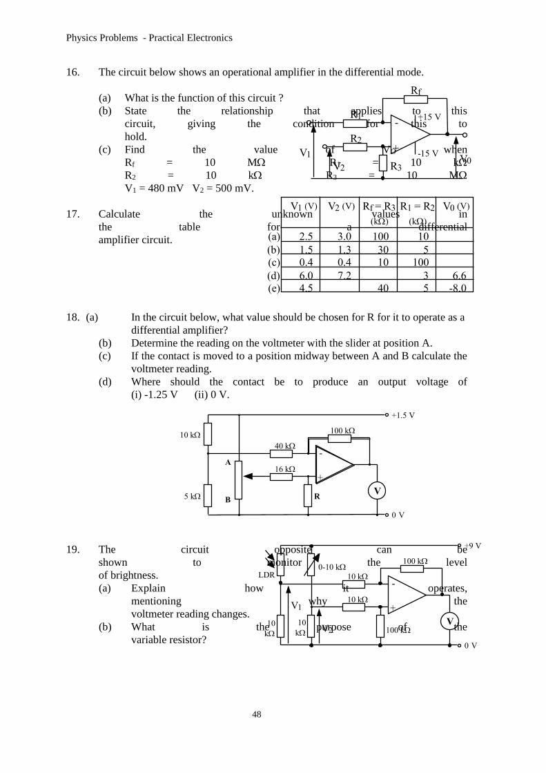
16. The circuit below shows an operational amplifier in the differential mode.
(a) What is the function of this circuit ?
(b) State the relationship that applies to this
circuit, giving the condition for this to
hold.
(c) Find the value of VO when
Rf = 10 M R1 = 10 k
R2 = 10 k R3 = 10 M
V1 = 480 mV V2 = 500 mV.
17. Calculate the unknown values in
the table for a differential
amplifier circuit.
18. (a) In the circuit below, what value should be chosen for R for it to operate as a
differential amplifier?
(b) Determine the reading on the voltmeter with the slider at position A.
(c) If the contact is moved to a position midway between A and B calculate the
voltmeter reading.
(d) Where should the contact be to produce an output voltage of
(i) -1.25 V (ii) 0 V.
19. The circuit opposite can be
shown to monitor the level
of brightness.
(a) Explain how it operates,
mentioning why the
voltmeter reading changes.
(b) What is the purpose of the
variable resistor?

Physics Problems - Practical Electronics
49
20. (a) Calculate the gain of the circuit shown.
(b) At what value of (i) V0 (ii) V1 will the transistor switch on ?
(c) Write down a rule which will allow you to predict whether a transistor is on
or off. Remember the polarity of the base-emitter voltage is important.
21. State if the transistors below are switched on or off.
-
+
1 M
100
k
VVV1
V0
c
e
b
0 V
+6 V-Vs
(a)
-5 V
0 V
(e)
-5 V
-3 V
(c)
-5 V
0 V
(g)
-5 V
-2 V
(b)
+5 V
0 V
(f)
+5 V
+9 V
(d)
+5 V
0V
(h)
-5 V
-9 V
Physics Problems - Practical Electronics
50
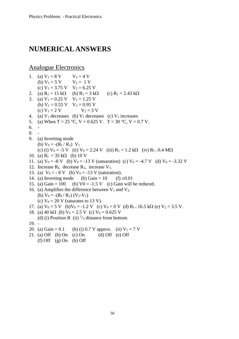
NUMERICAL ANSWERS
Analogue Electronics
1. (a) V1 = 8 V V2 = 4 V
(b) V1 = 5 V V2 = 1 V
(c) V1 = 3.75 V V2 = 6.25 V
2. (a) R1 = 15 k (b) R1 = 3 k (c) R1 = 2.43 k
3. (a) V1 = 0.25 V V2 = 1.25 V
(b) V1 = 0.55 V V2 = 0.95 V
(c) V1 = 2 V V2 = 3 V
4. (a) V1 decreases (b) V1 decreases (c) V1 increases
5. (a) When T = 25 °C, V = 0.625 V. T = 30 °C, V = 0.7 V.
6. -
8. -
9. (a) Inverting mode
(b) V0 = -(Rf / R1) V1
(c) (i) V0 = -5 V (ii) V0 = 2.24 V (iii) R1 = 1.2 k (iv) Rf = 0.4 M
10. (a) Rf = 35 k (b) 10 V
11. (a) V0 = -8 V (b) V0 = -13 V (satuaration) (c) V0 = -4.7 V (d) V0 = -3.32 V
12. Increase Rf, decrease R1, increase V1.
13. (a) V0 = - 8 V (b) V0 = -13 V (saturation).
14. (a) Inverting mode (b) Gain = 10 (f) ±0.01
15. (a) Gain = 100 (b) V0 = -1.5 V (c) Gain will be reduced.
16. (a) Amplifies the difference between V1 and V2.
(b) V0 = -(Rf / R1) (V2-V1)
(c) V0 = 20 V (saturates to 13 V).
17. (a) V0 = 5 V (b)V0 = -1.2 V (c) V0 = 0 V (d) Rf = 16.5 k (e) V2 = 3.5 V.
18. (a) 40 k (b) V0 = 2.5 V (c) V0 = 0.625 V
(d) (i) Position B (ii) 1/3 distance from bottom.
19. -
20. (a) Gain = 0.1 (b) (i) 0.7 V approx. (ii) V1 = 7 V
21. (a) Off (b) On (c) On (d) Off (e) Off
(f) Off (g) On (h) Off


![Physics NATIONAL QUALIFICATIONS Specimen …smarshallsay.weebly.com/uploads/3/1/4/6/3146892/physics...[C272/SQP362] NATIONAL QUALIFICATIONS Physics Time: 2 hours 30 minutes Higher](https://static.fdocuments.net/doc/165x107/5e7c54528bacdc646e5180d8/physics-national-qualifications-specimen-c272sqp362-national-qualifications.jpg)