SECTION 02731 - GRAVITY SANITARY SEWERS
40
Westfield Standard – 4/14 02731-1 SECTION 02731 - GRAVITY SANITARY SEWERS PART 1 - GENERAL 1.1 GENERAL A. This section covers all work necessary for the installation of gravity sanitary sewers and related items complete, including manholes, junction chambers, diversion chambers, house services, and miscellaneous concrete structures. B. Sewer pipe shall be the size and material type shown on the drawings and shall meet all requirements of these specifications and 327 IAC 3. 1.2 PIPE MARKING Each length of pipe shall bear the name or trademark of the manufacturer, the location of the plant, and the date of manufacture. Each length shall likewise be marked to designate the class or strength of the pipe. The marking shall be made on the exterior or interior of the pipe barrel near the bell or groove end and shall be plainly visible. PVC pipe shall be green. HDPE pipe shall have permanently extruded stripes on three (3) or four (4) sides according to the following schedule: Sanitary Sewer: Green Stripes 1.3 SUBMITTALS Before construction and preferably before fabrication, the Contractor shall submit to the Utility and/or designee for approval calculations on the thickness or strength class and drawings showing pipe lengths, joints, and other construction and installation details. All pipe furnished shall be fabricated only in accordance with the drawings and these specifications. 1.4 QUALITY ASSURANCE A. Performance Tests: The Contractor shall test all gravity sewers constructed. The Contractor shall constantly check horizontal and vertical alignment. Testing for vertical deflection in the case of non-rigid pipe and sewer watertightness testing in the case of all gravity sewers and hydrostatic testing of ductile iron pipe shall be as specified in this Section. B. Line and Grade Requirements: The Contractor shall provide assurance to the Utility and/or designee that the sewer is laid accurately to the required line and grade as shown on the drawings. The Contractor shall utilize a
Transcript of SECTION 02731 - GRAVITY SANITARY SEWERS

Westfield Standard – 4/14 02731-1
SECTION 02731 - GRAVITY SANITARY SEWERS
PART 1 - GENERAL
1.1 GENERAL
A. This section covers all work necessary for the installation of gravity
sanitary sewers and related items complete, including manholes, junction
chambers, diversion chambers, house services, and miscellaneous concrete
structures.
B. Sewer pipe shall be the size and material type shown on the drawings and
shall meet all requirements of these specifications and 327 IAC 3.
1.2 PIPE MARKING
Each length of pipe shall bear the name or trademark of the manufacturer, the
location of the plant, and the date of manufacture. Each length shall likewise be
marked to designate the class or strength of the pipe. The marking shall be made
on the exterior or interior of the pipe barrel near the bell or groove end and shall
be plainly visible. PVC pipe shall be green. HDPE pipe shall have permanently
extruded stripes on three (3) or four (4) sides according to the following schedule:
Sanitary Sewer: Green Stripes
1.3 SUBMITTALS
Before construction and preferably before fabrication, the Contractor shall submit
to the Utility and/or designee for approval calculations on the thickness or
strength class and drawings showing pipe lengths, joints, and other construction
and installation details. All pipe furnished shall be fabricated only in accordance
with the drawings and these specifications.
1.4 QUALITY ASSURANCE
A. Performance Tests: The Contractor shall test all gravity sewers
constructed. The Contractor shall constantly check horizontal and vertical
alignment. Testing for vertical deflection in the case of non-rigid pipe and
sewer watertightness testing in the case of all gravity sewers and
hydrostatic testing of ductile iron pipe shall be as specified in this Section.
B. Line and Grade Requirements: The Contractor shall provide assurance to
the Utility and/or designee that the sewer is laid accurately to the required
line and grade as shown on the drawings. The Contractor shall utilize a

Westfield Standard – 4/14 02731-2
laser beam instrument to lay and check the alignment and grade between
manholes. Before proceeding with the next section of sewer, the last
section shall be checked for proper line and grade. Variations from a
uniform line and grade as shown on the drawings and described below
shall be cause for the line to be rejected.
1. Variance from established line and grade shall not be greater than
1/32 of an inch per inch of pipe diameter and not to exceed 1/2
inch, provided that such variation does not result in a level or
reverse sloping invert; provided also that the variation in the invert
elevation between adjoining ends of pipe, due to non-concentricity
of joining surface and pipe interior surfaces, does not exceed 1/64
inch per inch of pipe diameter or 1/2 inch maximum.
C. Test Sections
1. Initial Performance Test: An initial performance and leakage test
will be performed on the first sections of sanitary sewer
constructed of approximately 600 feet in length of each size and
type sewer material installed. No additional sewer pipe shall be
installed until the first section of sewer of each size and type of
sewer material has satisfactorily passed the test for line and grade
and the leakage test.
2. Subsequent Performance Testing: After the initial performance
test and leakage test and as work progresses, the Utility or designee
may designate additional sections for testing as conditions in his
opinion warrant. If a review of the Contractor's workmanship
leads the Utility or designee to question whether or not the
tolerances and standards specified are being met, the Utility or
designee, reserves the right to select other locations and lengths to
be tested. The Utility or designee shall notify the Contractor of the
location where a test is to be required not later than 15 days after
the sewer installation has been completed. Unless otherwise
authorized, the Contractor shall arrange to commence the test
within 15 days after the sewer has been installed or 15 days after
receiving notification by the Utility or designee, whichever date is
later.
3. Final Performance Testing for Acceptance: Before acceptance for
all new sanitary sewers, the Contractor and the Utility or designee
shall check all sewers, even if previously checked, for accurate
alignment and grade. Also, all sanitary sewers shall be tested as
specified in Articles 3.10 through 3.14 of this Section for
watertightness. The program of testing whether by infiltration,
Westfield Standard – 4/14 02731-3
exfiltration, air testing, or vacuum testing shall be determined by
the Utility.
1.5 LENGTH OF OPEN TRENCH
Except by permission of the Utility or designee not more than 100 feet of trench
shall be opened at any one time. Not more than 30 feet of trench may be opened
in advance of the completed pipe laying operation, and not more than one street
crossing may be obstructed by the same trench at any one time.
1.6 RELATION TO WATER MAINS AND STORM SEWERS
A. All storm sewer crossings must be in accordance with the WPWD
Standards Section 03500. Should specific conditions prevent this
separation, the Contractor shall notify the WPWD for specific instructions
regarding the treatment of the separation. Sanitary sewers must be laid at
least 10 feet horizontally from any existing or proposed storm sewer and
whenever the sanitary sewer crosses a storm sewer, it should be laid at
least 18 inches below or above the main.
B. All water main crossings must be in accordance with 327 IAC 3-6-9 and
327 IAC 8-3.2-9 and at least a 45 degree angle.
C. Sewers must be laid at least 10 feet horizontally from any existing or
proposed water main. The distance is to be measured outside edge to
outside edge. Should specific conditions prevent this separation, the
Contractor shall notify the WPWD for specific instructions regarding the
treatment of the separation. Special conditions (existing conditions) may
allow installation of the sewer closer to a water main, provided that the
water main is in a separate trench or on an undisturbed earth shelf located
on one side of the sewer and at an elevation so the bottom of the water
main is at least 18 inches above the top of the sewer. It will be necessary
to install 150 psi water main pipe and joints as sewer pipe for the
congested areas.
D. Whenever the sewer crosses a water main, it should be laid at least 18
inches below the main, or the water main should be relaid with fittings to
cross over the sewer. The crossing shall be arranged so that the sewer
joints will be equidistant and as far as possible from the water main joints.
Any joints within a distance of 10 feet from either side of the crossing
must be compression joints. All crossings must be at a minimum of 45
degrees from center lines of the sanitary sewer and the water main.
E. When it is impossible to obtain proper horizontal and vertical separation
as stipulated above, the sewer pipe shall be designed and constructed equal
Westfield Standard – 4/14 02731-4
to 150 psi water pipe, and shall be pressure tested to assure watertightness
prior to backfilling. Maximum distance between sewer pipe joints and
water pipe shall be provided where vertical separation is a problem.
PART 2 - PRODUCTS
2.1 MATERIALS
A. All pipe shall be a type approved by IDEM.
B. Sewers 15 Inches or Smaller
1. Sewers 15 inches in diameter or smaller shall be PVC composite
pipe, polyvinyl chloride pipe or ductile iron pipe.
2. PVC Composite Sewer Pipe and Fittings: PVC composite sewer
pipe and fittings shall conform to ASTM D2680, latest revision.
3. Polyvinyl Chloride Pipe and Fittings
a. PVC pipe and fittings shall conform to ASTM D3034 SDR
35 or 26 Type PSM, latest revision.
b. SDR 26 PVC pipe and fittings shall be used in depths
exceeding 14 feet.
c. Maximum diameter of PVC sewer pipe to be used is 15
inches.
4. Ductile Iron Pipe and Fittings: Ductile iron pipe and fittings shall
conform to the requirements of ANSI/ASTM A746, Ductile Iron
Gravity Sewer Pipe.
a. Thickness class requirements of ductile iron pipe to be used
in conveyance of sanitary sewage by gravity shall be
minimum thickness of Class 350 unless otherwise noted for
standard length pipe.
b. Outside surfaces of the pipe and fittings shall be bituminous
coated complying with ANSI/AWWA A21.51/C151 and
ANSI/AWWA A2110/C110.
c. Inside surfaces of all pipes, fittings and adapters shall be
lined with cement mortar and a bituminous seal coat.
Cement mortar lining and bituminous seal coat shall meet
the requirements of ANSI/AWWA A21.4/C104.
Westfield Standard – 4/14 02731-5
d. Ductile iron pipe and fittings shall be push-on type
conforming to ANSI A21.11 (AWWA C111), latest
revision. Fittings shall be ductile iron and shall comply
with ANSI Specification A21.10, latest revision, with
mechanical joints for 150 psi working pressure.
e. Polyethylene encasement for ductile iron force mains shall
be installed and shall meet the requirements of
ANSI/AWWA C105/A21.5. Installation of the
polyethylene encasement shall be omitted if written
approval is made by the ductile iron pipe manufacturer
and/or the Utility. Contractor/Developer shall be required
to provide soils testing results for corrosivity at no
additional charge to the Utility or designee if omission of
the polyethylene encasement is proposed. All fittings and
adapters shall be wrapped in a minimum of 3 mil or greater
plastic.
5. Joints for PVC Sewer Pipe
a. Joints on PVC sewer pipe shall be the integral bell type
gasketed joint designed so that when assembled the
elastomeric gasket inside the bell is compressed radially on
the pipe spigot to form a positive seal. The joint shall be so
designed to avoid displacement of the gasket when installed
in accordance with manufacturer's recommendations. The
joint shall comply with the physical requirements of ASTM
D3212, and the gasket shall be the only element depended
upon to make the joint flexible and watertight.
b. All PVC Pipe entering a manhole shall have a manhole
waterstop gasket as supplied by the manufacturer firmly
clamped around the pipe at the manhole.
C. Sewers Greater than 15 inches
1. Ductile Iron Pipe and Fittings: Ductile iron pipe and fittings shall
conform to the requirements of ANSI/ASTM A746, Ductile Iron
Gravity Sewer Pipe.
a. Thickness class requirements of ductile iron pipe to be used
in conveyance of sanitary sewage by gravity shall be
minimum thickness of Class 350 unless otherwise noted for
standard length pipe.
Westfield Standard – 4/14 02731-6
b. Outside surfaces of the pipe and fittings shall be bituminous
coated complying with ANSI/AWWA A21.51/C151 and
ANSI/AWWA A2110/C110.
c. Inside surfaces of the entire pipe, fittings and adapters shall
be lined with cement mortar and a bituminous seal coat.
Cement mortar lining and bituminous seal coat shall meet
the requirements of ANSI/AWWA A21.4/C104.
d. Ductile iron pipe and fittings shall be push-on type
conforming to ANSI A21.11 (AWWA C111), latest
revision. Fittings shall be ductile iron and shall comply
with ANSI Specification A21.10, latest revision, with
mechanical joints for 150 psi working pressure.
e. Polyethylene encasement for ductile iron force mains shall
be installed and shall meet the requirements of
ANSI/AWWA C105/A21.5. Installation of the
polyethylene encasement shall be omitted if written
approval is made by the ductile iron pipe manufacturer
and/or the Utility. Contractor/Developer shall be required
to provide soils testing results for corrosivity at no
additional charge to the Utility or designee if omission of
the polyethylene encasement is proposed. All fittings and
adapters shall be wrapped in a minimum of 3 mil or greater
plastic.
D. Fittings
1. Fittings such as wyes and bends shall be made in such a manner as
will provide strength and watertightness at least equal to the class
of the adjacent main line pipe to which they are jointed and shall
conform to all other requirements specified for pipe of
corresponding class and internal diameter. Joints shall be of the
same type as used on the adjoining pipe.
2. Fabricated branches for wyes and tees shall be securely attached to
the wall of the pipe in a watertight manner and shall be flush with
the inside surface of the pipe. The branches shall have their axes
perpendicular to the longitudinal axis of the pipe. Wye branches
shall have their axes approximately 60 degrees for clay pipe and 45
degrees for concrete pipe from the longitudinal axis of the pipe,
measured from the bell end. Pipe reinforcement shall not be
interrupted beyond a radial distance of 3 inches outside of the
fitting.
Westfield Standard – 4/14 02731-7
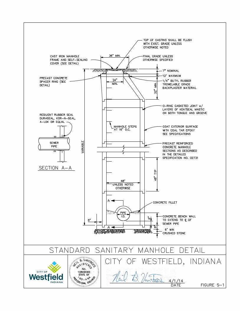
E. Manholes and Other Structures: Manholes shall be constructed of
monolithic concrete or precast manhole sections. Precast manhole
sections shall conform to requirements of ASTM C478, latest revision.
1. Materials for manholes, junction chambers, diversion chambers,
and miscellaneous concrete structures shall comply with the
following:
a. Concrete for precast manhole sections shall be 3000 psi
concrete. Monolithic manholes shall use 4000 psi concrete.
Ready-mix concrete shall conform to ASTM C94 Alternate
2. Maximum size of aggregate shall be 1-1/2 inches.
Slump shall be between 2 and 4 inches.
b. Forms for chamber and structures shall be plywood or other
approved material. Steel forms shall be used for the inside
face of monolithic concrete manholes.
c. Reinforcing steel shall conform to ASTM A615, Grade 40
deformed bars, or ASTM A616 and Grade 40 deformed
bars.
d. Mortar Materials
(1) Sand - ASTM Designation C144, passing a No. 8
sieve.
(2) Cement - ASTM Designation C150, Type 1.
(3) Water - shall be potable.
e. All joints shall be fully sealed and waterproofed. Rubber
gaskets for precast concrete manhole sections shall meet the
requirements of ASTM C443. The gasket shall be the sole
element depended upon to make the joint flexible and
watertight.
f. The manufacturer of the precast manholes shall provide
core-drilled openings to produce a smooth, uniform,
cylindrical hole of the proper size to accommodate a
resilient connector meeting the requirements of ASTM
C923 for all sewers entering and leaving the manhole. The
resilient connectors shall be either Press-Seal Gasket Corp.,
which provides PSX gasket or Press Wedge II; or similar
flexible manhole sleeves furnished by Kor-N-Seal by NPG
Systems, Inc.; or approved equal.
Westfield Standard – 4/14 02731-8
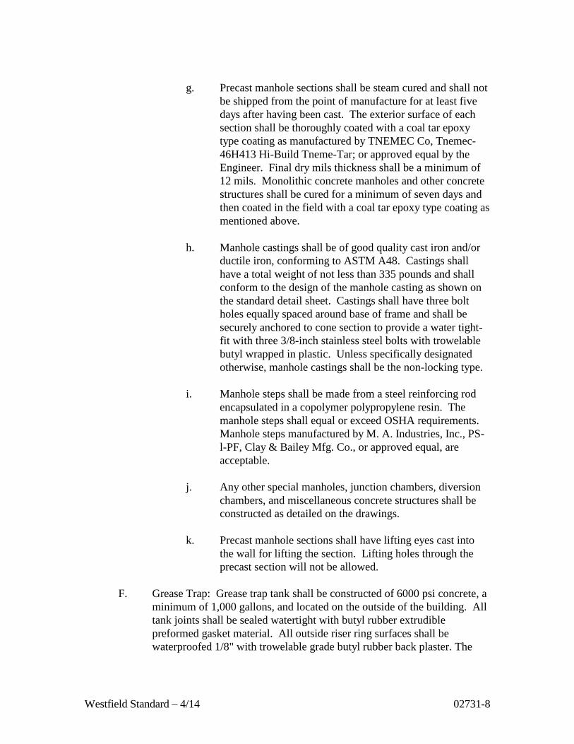
g. Precast manhole sections shall be steam cured and shall not
be shipped from the point of manufacture for at least five
days after having been cast. The exterior surface of each
section shall be thoroughly coated with a coal tar epoxy
type coating as manufactured by TNEMEC Co, Tnemec-
46H413 Hi-Build Tneme-Tar; or approved equal by the
Engineer. Final dry mils thickness shall be a minimum of
12 mils. Monolithic concrete manholes and other concrete
structures shall be cured for a minimum of seven days and
then coated in the field with a coal tar epoxy type coating as
mentioned above.
h. Manhole castings shall be of good quality cast iron and/or
ductile iron, conforming to ASTM A48. Castings shall
have a total weight of not less than 335 pounds and shall
conform to the design of the manhole casting as shown on
the standard detail sheet. Castings shall have three bolt
holes equally spaced around base of frame and shall be
securely anchored to cone section to provide a water tight-
fit with three 3/8-inch stainless steel bolts with trowelable
butyl wrapped in plastic. Unless specifically designated
otherwise, manhole castings shall be the non-locking type.
i. Manhole steps shall be made from a steel reinforcing rod
encapsulated in a copolymer polypropylene resin. The
manhole steps shall equal or exceed OSHA requirements.
Manhole steps manufactured by M. A. Industries, Inc., PS-
l-PF, Clay & Bailey Mfg. Co., or approved equal, are
acceptable.
j. Any other special manholes, junction chambers, diversion
chambers, and miscellaneous concrete structures shall be
constructed as detailed on the drawings.
k. Precast manhole sections shall have lifting eyes cast into
the wall for lifting the section. Lifting holes through the
precast section will not be allowed.
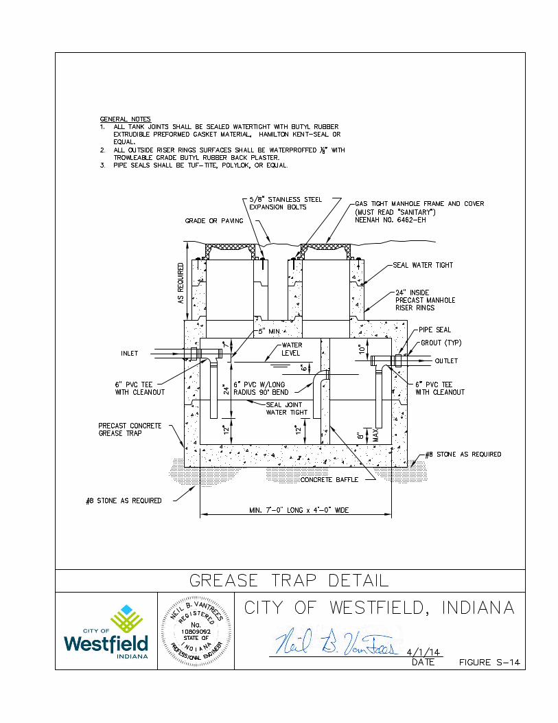
F. Grease Trap: Grease trap tank shall be constructed of 6000 psi concrete, a
minimum of 1,000 gallons, and located on the outside of the building. All
tank joints shall be sealed watertight with butyl rubber extrudible
preformed gasket material. All outside riser ring surfaces shall be
waterproofed 1/8" with trowelable grade butyl rubber back plaster. The
Westfield Standard – 4/14 02731-9
Contractor shall provide a submittal to the Utility or designee on the
specifications for the grease trap prior to construction.
PART 3 - EXECUTION
3.1 INSPECTION AND REJECTION OF PIPE
A. The quality of all materials, the process of manufacture, and the finished
pipe shall be subject to inspection and approval by the Utility or designee.
Such inspection may be made at the place of manufacture or on the
construction site after delivery, or at both places; and the pipe shall be
subject to rejection at any time on account of failure to meet any of the
specifications' requirements even though sample pipes may have been
accepted as satisfactory at the place of manufacture.
B. Prior to being lowered into the trench, each pipe shall be carefully
inspected, and those not meeting the specifications shall be rejected and
shall be removed from the construction site.
C. Any pipe which is damaged, bleached, or deemed unsuitable by the Utility
or designee will be rejected and replaced solely at the Contractor's
expense.
3.2 HANDLING PIPE
A. Each pipe section shall be handled into its position in the trench only in
such manner approved by the Utility or designee. The Contractor will be
required to furnish slings, straps, and other approved devices to permit
satisfactory support of all parts of the pipe when it is lifted.
B. Any fitting showing a crack and any fitting or pipe which has received a
severe blow that may have caused an incipient fracture, even though no
such fracture can be seen, shall be marked as rejected and removed at once
from the work.
C. In any pipe showing a distinct crack and in which it is believed there is no
incipient fracture beyond the limits of the visible crack, the cracked
portion, if so approved, may be cut off by and at the expense of the
Contractor before the pipe is laid so that the pipe used may be perfectly
sound. The cut shall be made in the sound barrel at a point at least 12
inches from the visible limits of the crack.

Westfield Standard – 4/14 02731-10
D. All cutting shall be done with a machine having steel cutters or knives
adapted to the purpose. All cut ends shall be examined for possible cracks
caused by cutting.
3.3 NOTICE OF CONSTRUCTION
The Utility and/or designee shall be notified 48 hours in advance when the pipes
are to be laid in the trench. At least 15 feet of the pipe shall, under ordinary
circumstances, be laid before covering begins.
3.4 LAYING PIPE
A. All pipes shall be reinspected for soundness and damage due to handling
immediately before being lowered into the trench. Any pipe found to be
unsound or damaged will be rejected and shall be removed immediately
from the site of the work.
B. All pipes shall be laid accurately to the required line and grade as shown
on the drawings, and in the manner prescribed by the pipe manufacturer
and appropriate ASTM Specifications, to form a close, concentric joint
with the adjoining pipe and to bring the invert of each section to the
required grade. The supporting of pipe on block will not be permitted.
C. Pipe laying shall proceed upgrade, beginning at the lower end of the sewer.
D. All sewers shall be designed and constructed to give mean velocities,
when flowing full, of not less than 2.0 feet per second (0.6 m/s), based on
Manning’s formula using an “n” value of 0.013. The following are the
recommended minimum slopes which should be provided; however,
slopes greater than these are desirable. Refer to 327 IAC 3-6-12 for
anchoring requirements for extremely steep slopes.
Nominal Sewer Size
Minimum Slope in Feet
Per 100 Feet (m/100m)
8 inch (200 mm) 0.40
10 inch (250 mm) 0.28
12 inch (300 mm) 0.22
14 inch (350 mm) 0.17
15 inch (375 mm) 0.15
16 inch (400 mm) 0.14
18 inch (450 mm) 0.12
21 inch (525 mm) 0.10
24 inch (600 mm) 0.08
27 inch (675 mm) 0.067
30 inch (750 mm) 0.058

Westfield Standard – 4/14 02731-11
Nominal Sewer Size
Minimum Slope in Feet
Per 100 Feet (m/100m)
33 inch (825 mm) 0.052
36 inch (900 mm) 0.046
39 inch (975 mm) 0.041
42 inch (1050 mm) 0.037
E. Watertight work in conformance with 327 IAC 3 is required, and the
Contractor shall construct the sewers with the type of joint specified
therein.
F. All pipes shall be laid to the line and grade as shown on the drawings.
Variations from a uniform line and grade as shown on the drawings shall
be cause for the line to be rejected. Do not lay pipe in water or when the
trench or weather conditions are unsuitable for proper installation.
G. Every pipe and fitting shall be cleaned of all debris, dirt, and other foreign
material before being laid, and shall be kept clean until accepted in the
completed work. When bell and spigot pipe is laid, the bell of the pipe
shall be cleaned of tar or other obstruction and wiped out before the clean
spigot of the next pipe is inserted into it. The joint shall be made in a
satisfactory manner in accordance with the recommendations of the
manufacturer on particular type of joint. All joint work shall be done by
experienced workmen.
H. PVC (polyvinyl chloride) gravity sewer pipe and fittings, ASTM D3034
SDR 35, shall be installed in accordance with the directions contained in
ASTM D2321. Only materials classified as Class I will be acceptable for
bedding, haunching, and initial backfill of the pipe placed and compacted
in accordance with ASTM D2321.
I. Joints on PVC pipe shall be the integral bell type gasketed joint designed
so that when assembled the elastomeric gasket inside the bell is
compressed radially on the pipe spigot to form a positive seal. The joint
shall be so designed to avoid displacement of the gasket when installed in
accordance with the manufacturer's recommendations. The gasket shall be
the only element depended upon to make the joint flexible and watertight.
J. All PVC pipe entering a manhole shall have manhole waterstop gasket as
supplied by the manufacturer firmly clamped around the pipe.
K. All PVC pipe shall have a deflection test performed by the Contractor 30
days after the last stick of pipe has been placed in the presence of the
Utility or designee.

Westfield Standard – 4/14 02731-12
L. All pipe shall be bedded as described in this specification under Pipe
Bedding. Bell holes shall be excavated in advance of pipe laying so the
entire pipe barrel will bear uniformly on the prepared subgrade.
M. Each length of pipe shall be mechanically pulled "home" with a winch or
come-along against the section previously laid and held in place until the
trench and bedding are prepared for the next pipe section. Care shall be
taken in laying the pipe so not to damage the bell end of the pipe.
Mechanical means consisting of a cable placed inside the pipe with a
winch, jack, or come-along shall be considered to pull the pipe home
where pushing the pipe will not result in a joint going completely home
and staying in place. Pushing the pipe home shall be done by means of a
block and push bar. Use of hydraulic excavating equipment as the means
of pushing or moving the pipe to grade will not be permitted.
N. The Contractor shall use laser beam equipment to maintain accurate
alignment and grade. A qualified operator shall handle the equipment
during the course of construction. If bending of the laser beam due to air
temperature variations or dust in the air is apparent "within the pipe" units,
a fan shall be provided to circulate the air. However, air velocity shall not
be so excessive as to cause pulsating or vibrating of the beam. Survey
instruments may be used for checking alignment and grade if questions
arise about the accuracy of the work.
O. Open excavation shall be satisfactorily protected at all times. At the end
of each day's work, the open ends of all pipes shall be protected against the
entrance of animals, earth, or debris by bulkheads or stoppers. The
bulkheads or stoppers shall be perforated to allow passage of water into
the installed pipe line to prevent flotation of the pipe line. Any earth or
other material that may find entrance into the main sewer or into any
lateral sewer through any such open end of unplugged branch must be
removed at the Contractor's expense.
P. The Contractor shall conduct a leakage test as described in Sewer Tests of
the specification on the first section of sewer of each size and type sewer
material installed. No additional sewer pipe shall be installed until the
first reach of sewer of each size and each type sewer material has
satisfactorily passed the leakage test.
Q. The Contractor shall prevent all ground water and surface water from
entering the existing sewer system during construction of a new sewer or
force main extension.
Westfield Standard – 4/14 02731-13
R. Sanitary sewer designs that require crossing a county legal drain shall be
approved and constructed per the latest standards of the Hamilton County
Surveyor’s Office.
S. Sanitary sewers shall be covered with at least a foot of bedding material
and thirty six (36) inches of approved backfill material.
T. At least 15 feet of the pipe shall, under ordinary circumstances, be laid
before backfilling begins.
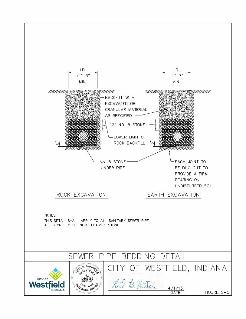
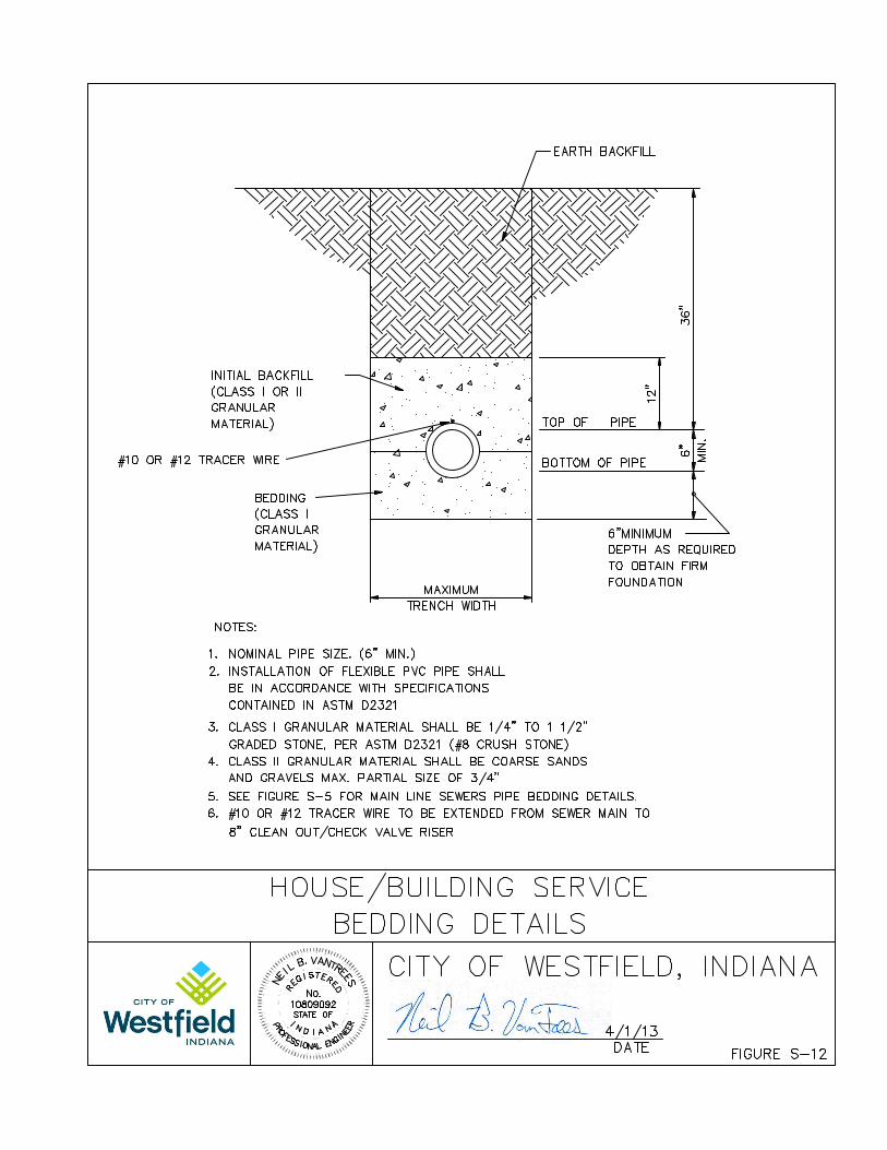
3.5 PIPE BEDDING AND HAUNCHING
A. Each pipe section shall be laid in a firm foundation of bedding material
and haunched and backfilled with care.
B. Prior to pipe installation, carefully bring bedding material to grade along
the entire length of pipe to be installed. To provide adequate support for
the pipe, the following bedding procedures are recommended.
1. When Class I material is used for bedding, little or no compaction
is necessary due to the nature of the angular particles. A depth of 6
inches is generally sufficient to provide uniform bedding.
C. Bedding material shall have a minimum thickness beneath the pipe of 6
inches or one-eighth of the outside diameter of the pipe, whichever is
greater, and shall extend up the sides of the pipe one-sixth of the outside
diameter of the pipe.
D. For rigid pipe, such as ductile iron, backfill between the bedding material
and a plane 12 inches over the top of the pipe shall be granular backfill.
E. For flexible pipe such as PVC, the placement of embedment material,
consisting of bedding, haunching, and initial backfill, must be done with
care. The ability of the pipe to withstand loading in a trench depends a
large part on the method employed in its installation. Class I material, as
defined in specification Section 02222, Article 2.1, paragraph A, shall be
used as embedment material for flexible pipe. Bedding thickness shall be
as specified in paragraph C of this Section. The haunching material (the
material from the bedding to the pipe springline) and initial backfill (the
material from the pipe springline to a plane 12-inches over the top of
pipe), shall be hand placed. Care must be taken to not cause damage by
compacting the material directly over the pipe.

Westfield Standard – 4/14 02731-14
F. In yielding subsoils, the trench bottom shall be undercut to the depth
necessary and backfilled with graded, crushed stone to form a firm
foundation.
G. Where excavation occurs in rock or hard shale, the trench bottom shall be
undercut and a minimum of 6 inches crushed stone bedding placed prior to
pipe installation. Additional payment for rock excavation shall be made
on "unit cost" projects only, and as prescribed under basis for payment.
3.6 MANHOLES AND OTHER STRUCTURES
A. Manholes shall meet all requirements of 327 IAC 3-6-16.
B. Manholes and other structures are to be constructed at locations shown on
the drawings and in accordance with the following specifications:
1. Precast concrete manhole sections shall conform to ASTM C478,
except as modified herein:
a. The joint design of the precast sections shall consist of a
bell or groove on one end of the unit of pipe and a spigot or
tongue on the adjacent end of the joining section.
b. The joint shall consist of a round rubber gasket confined in
a groove in the spigot end of the precast manhole section
and shall conform to Sections 6.1.6, 6.1.7 and 9 of ASTM
C443, latest revision and a 6 inch wide flexible butyl rubber
joint sealant between the outside joints. Inside manhole
joints are to be sealed with hydroplug or non-shrink grout
and brushed smooth.
2. Openings in manhole sections for sewer connections shall be core-
drilled at the point of manufacture and shall be done to produce a
smooth, uniform, cylindrical hole of proper size to accommodate a
resilient connector meeting requirements of ASTM C923. The
resilient connectors shall be either Press-Seal Gasket Corp., PSX
Gasket or Press-Wedge II; or similar flexible manhole sleeves
furnished by Kor-N-Seal by NPC Systems, Inc.; or approved equal.
3. Manhole bases shall be cast-in-place concrete, reinforced as shown
on the Standard Detail Sheet, or monolithic base and first section
combination. Manhole bases shall be cast or placed on a minimum
of 6 inches of compacted crushed stone.
Westfield Standard – 4/14 02731-15
4. Manhole channels or inverts shall be preformed and poured with
Class "B-1" concrete to the spring line of the connecting pipe. The
finished invert shall be a semi-circular shaped smooth channel
directing the flow to the downstream sewer.
5. Monolithic concrete manholes, junction chambers, and other cast-
in-place concrete structures shall be cured for a minimum of seven
days. The exterior surfaces shall then be coated thoroughly with a
coal tar epoxy type coating as manufactured by TNEMEC Co.,
Tneme-46H413 Hi-Build Tneme-Tar; or approved equal by the
Utility. Coating shall be 12 mil minimum dry film thickness. Each
joint of precast concrete manhole sections, lifting holes, and holes
left by the removal of cores shall be fully mortared and shall be
coated with a 12 mil minimum dry film thickness of coal tar epoxy
as specified upon reaching its final set.
6. Any additional holes cut in the field shall be drilled with a core-
drill or in a manner approved by the Utility or designee.
7. Manhole frames and lids shall weigh not less than 335 pounds and
be of good quality cast iron, conforming to ASTM A48. Unless
specifically designated otherwise, manhole castings shall be the
non-locking type. All manhole frames shall be cast with three
holes equally spaced around base of frame and shall be securely
anchored to cone section with three 3/8-inch stainless steel bolts,
nuts, and washers. The joint between the casting frame and cone
section shall be first sealed with cement mortar and then coated
with a pliable butyl rubber or a coal tar epoxy coating upon
reaching its final set to become a watertight joint.
8. Manhole steps shall be made from a steel reinforcing rod
encapsulated in a copolymer polypropylene resin. Steps shall be
placed as shown on the approved drawings.
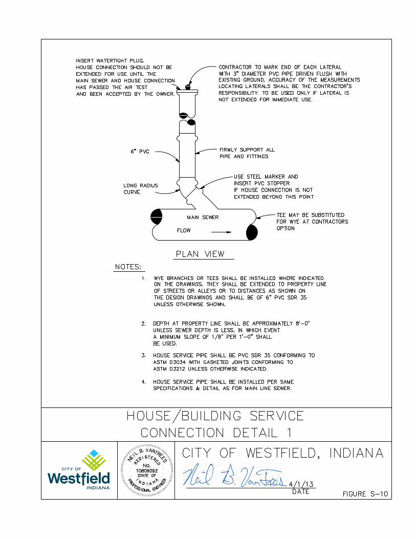
3.7 HOUSE/BUILDING SERVICES
A. The Contractor shall install 6-inch diameter house/building service sewer
shall be installed as shown on the Standard Detail Sheet. The
house/building service shall extend from a "wye" or "tee" fitting in the
main sewer line to the property line or easement line, unless stated
otherwise. Tapping into manholes for laterals shall not be permitted.
B. A backwater prevention valve shall be provided for each sanitary sewer
lateral. The backwater prevention valve shall be located outside the

Westfield Standard – 4/14 02731-16
structure and readily accessible at all times. The backwater prevention
valve shall be a clean-out/check valve per detail S-13.
C. The Contractor shall contact the individual property owners for the
preferred location of the house/building service to best suit the property
owner's needs. If the Contractor is unable to contact the property owner in
advance of laying the main sewer by or across the property, the Contractor
shall so notify the Utility or designee in writing.
D. Fittings for house/building service connections on a main line sewer 15
inches in diameter or smaller shall be tees or 45-degree wyes and shall be
of the same material as the main line sewer, unless otherwise approved by
the Utility.
E. House/building services and connections on main line sewers greater than
15 inches in diameter shall be of a type that will maintain the structural
integrity of the main line sewer and provide a watertight connection.
Intrusion of house/building services into the flow way of the main line
sewer shall not be permitted.
F. Six-inch lateral pipe shall connect to the main line sewer at an angle of 15
degrees to 45 degrees from the spring line and shall include the necessary
bends and straight pipe sections to reach the property line at the elevations
specified. A pipe stopper or a bell cap shall be placed on/in the last bell.
This stopper or bell cap should be compatible with the type of
infiltration/exfiltration test performed on the sewer.
G. The Contractor shall furnish and use the proper fittings, couplings, and
adapters suited to make the transition between different pipe materials
which will maintain the structural integrity and the watertightness of the
entire sewer system.
H. At the discretion of the Utility, when and where improper installation
practices are suspected or questionable bedding materials and methods are
employed, or where the installations are severe, the Contractor will have to
perform deflection testing on the 6 inch house laterals as specified in
Article 3.9.
I. Backfill around fittings and lateral pipe shall be carefully placed and
compacted to prevent damage from backfill settlement and shall be
installed in same manner as described for sewer installation.
J. The Contractor shall keep accurate horizontal and vertical location
measurements of each house/building service installed. The location of all
house/building services shall be shown on digital as-builts as described in
Westfield Standard – 4/14 02731-17
Section 01001, Article 1.14. The accuracy of the measurements shall be
the Contractor's responsibility.
3.8 STUBS, CONNECTIONS, BULKHEADS, AND MISCELLANEOUS ITEMS
OF WORK
A. Where special junction chambers are to be constructed or where existing
sewers carrying sanitary sewage are encountered, the Contractor shall
provide and maintain temporary connections to prevent a nuisance.
B. Where called for shop connections and stubs for future sewer connections
shall be provided.
C. New sewer main connections to existing manholes shall be core drilled in
to the existing structure and providing a watertight connection.
D. The Contractor shall not connect any existing sewers or house/building
services prior to the completion of the exfiltration/infiltration tests, air
tests, and acceptance of the sewer without the permission of the Utility.
E. Dog house manholes will not be permitted.
3.9 VERTICAL DEFLECTION TESTING
For PVC pipe, the entire length of installed mainline pipe shall be tested for
acceptance with an approved go-no-go mandrel under the observation of the
Utility or designee. The testing shall be conducted after the final backfill has been
in place for at least 30 days. No pipe shall exceed a deflection of 5%. The
deflection test shall be run using a mandrel having a diameter equal to 95% of the
inside diameter of the pipe in accordance with ASTM D3034 Appendixes. The
pipe shall be measured in compliance with ASTM D2122. All pipe exceeding the
allowable deflection shall be replaced, repaired, and retested.
3.10 INFILTRATION LIMITS
A. Maximum infiltration/exfiltration limits for all new sanitary sewers shall
not exceed 200 gallons per inch of diameter per mile of pipe per 24 hours
for any section of the system. All sections of the sewer shall be tested, and
any sections not meeting this infiltration standard shall be repaired and
retested.
B. The Contractor shall note the special provision under Article 3.4,
Paragraph P, that the first section of sewer of each size and type of sewer
shall be given a satisfactory leakage test before proceeding with any
additional construction.
Westfield Standard – 4/14 02731-18
3.11 SEWER WATERTIGHTNESS TESTING
A. Infiltration testing must be performed in accordance with 327 IAC 3-6-
19.d. Tests for watertightness shall be conducted on all installed sewers in
the presence of and in the manner accepted by the Utility or designee. The
Contractor shall furnish and install all equipment necessary for the sewer
tests.
B. Watertightness tests shall be conducted on short sections of the sewer as
soon as the manholes have been constructed and the backfilling
completed.
C. Where the section tested is in excess of the allowable limits, the
Contractor shall correct the construction of the sewer so that the section
tested is within the allowable limit. All methods and materials used in the
repair shall be approved by the Utility or designee.
D. The program of testing shall fit the conditions as determined by the Utility
or designee using Air Test for Leakage. When ductile iron pipe with push-
on type joints are used for sewer construction, a hydrostatic pressure test
shall be performed.
The existing or lowest manhole shall have a monitoring well installed to
the depth of the bottom of the pipe for the purposes of measuring ground
water elevation.
Immediately before air testing, the ground water level shall be determined
by the use of the monitoring well.
Alternate groundwater monitoring methods shall require the prior written
approval of the Utility.
1. The Air Test for Leakage
a. The air test for leakage shall be used to test sewer
watertightness on all sewer pipes unless otherwise noted.
b. The ends of the sewer section being tested shall be sealed
and properly blocked. The seal at one end shall have an
orifice through which to pass air into the pipe. An air
supply shall be connected to the orifice at one end of the
section. The air supply line will contain an off-on gas valve
and a pressure gauge having a range from 0 to 25 psi. The
gauge shall have minimum divisions of 0.10 psi and shall
Westfield Standard – 4/14 02731-19
have an accuracy of the nearest ±0.1 psi. The seals at each
manhole shall be properly blocked to prevent displacement
while the line is under pressure.
2. Procedure for Conducting a Low Pressure Air Test
a. Clean pipe to be tested by propelling a snug fitting inflated
ball through the pipe by water pressure or other adequate
method. This step is important because it not only flushes
out construction debris but the water used to flush the pipe
dampens the pipe wall. The rate of air loss through pipe
wall permeation can be significant on dry pipes.
b. Plug all pipe outlets with pneumatic plugs having a sealing
length equal to or greater than the diameter of the pipe to be
tested. The pneumatic plug shall be able to resist internal
testing pressures without requiring external bracing.
c. The groundwater level surrounding the section of sewer
under testing shall be determined by one of the procedures
previously outlined in paragraph D. If the groundwater
table is above the pipe, then test pressures shall be
increased by the corresponding increment (e.g., if the
groundwater table is above the lowest crown of the pipe,
the air pressure should be increased 0.433 times each foot
of water.)
d. Once the pipe outlet plugs are securely in place, pressurized
air is introduced to the system. The air shall be fed through
a single control panel with three individual hose
connections as follows:
(1) from control panel to pneumatic plugs for inflation
in sewer pipe;
(2) from control panel to sealed line for introducing the
pressurized air;
(3) from sealed line to control panel. This line will
enable continuous monitoring of the air pressure
rise in the sealed line.
e. The air shall be introduced slowly to the section of pipe
under evaluation until the internal air pressure is raised to
7.0 psig greater than the hydrostatic pressure head created
by the existence of groundwater that is over the pipe
section.
Westfield Standard – 4/14 02731-20
f. A minimum of two minutes shall be provided for the air
pressure to stabilize to conditions within the pipe. (This
stabilization period is necessary for variations in
temperature to adjust to the interior pipe conditions.) Air
may be added slowly to maintain a minimum pressure of
7.0 psig for at least two minutes.
g. After the stabilization period, when the pressure reaches
exactly 7.0 psig, the stopwatch shall be started; and when
the pressure reaches 6.0 psig, it is stopped. The portion of
the line being tested shall be acceptable if the time in
minutes for the air pressure to decrease from 7.0 psig to 6.0
psig is greater than the time shown in the following table:
Pipe Diameter Time
(Inches) (Minutes)
4 2.0
6 3.0
8 4.0
10 5.0
12 5.5
15 7.5
18 8.5
21 10.0
24 11.5
h. In areas where the groundwater is above the top of the pipe,
the test pressures shall be increased by 0.433 per foot of
groundwater (e.g., if the groundwater is 11-1/2 feet, the 7.0
to 6.0 pressure drop will be increased by 5 psi; the time
then will be measured for a pressure drop from 12.0 psi to
11.0 psi.)
3. Safety Precautions During Air Test
a. The air test may be dangerous if, because of ignorance or
carelessness, a line is improperly prepared. It is extremely
important that the various plugs be installed and braced in
such a way as to prevent blowouts. Inasmuch as a force of
250 pounds is exerted on an 8-inch plug by an internal pipe
pressure of 5 psi, it should be realized that sudden
expulsion of a poorly installed plug or of a plug that is
Westfield Standard – 4/14 02731-21
partially deflated before the pipe pressure is released can be
dangerous.
b. As a safety precaution, pressurizing equipment should
include a regulator set at perhaps 10 psi to avoid over-
pressurizing and damaging an otherwise acceptable line.
No one shall be allowed in the manholes during testing.
3.12 HYDROSTATIC TESTING
A. A hydrostatic test on ductile iron pipe with push-on type joints has two
purposes: one is to set the gaskets in place, and the other is to provide a
leakage test.
B. Said test shall include all ductile iron sewer pipes with push-on type joints
installed by the Contractor. The Contractor shall make arrangements with
the Utility and/or designee for scheduling the test after the sewer pipe has
been accepted as being ready for testing. The test shall be performed in
the presence of the Utility and/or designee on the day mutually agreed
upon.
C. Water for testing may be obtained from the Utility or designee. The cost
of the water supplied for such testing is to be paid by the Developer. The
Contractor shall furnish all necessary equipment, piping, pumps, fittings,
gauges, and operating personnel to properly conduct the test.
D. Hydrostatic test on ductile iron pipe with push-on type joints installed as
gravity sewers and siphons shall be in accordance with the following
provisions:
1. The ends of the sewer section being tested shall have test plugs or
caps adapted with a tap of adequate diameter to fill and pressurize
the system with water.
2. When a section is terminated at a manhole with a plain end
(spigot), the pipe must extend into the manhole of sufficient length
to accommodate a restraining cap. The benchwall shall be formed
in the manhole after the test section has been approved.
3. Water shall be introduced into the section to be tested at the lower
end. The upper end shall have an orifice at the top of the plug or
cap to expel air when filling the system with water. All air shall be
expelled from the pipe.
Westfield Standard – 4/14 02731-22
4. The test plugs or caps shall be capable of withstanding an internal
pressure of 175 psi.
5. The system shall be tested in conformance with Section 13 of
AWWA Specifications 600, at 50 pounds per square inch over a
period of not less than one hour. The system will not be acceptable
until all leaks have been repaired.
6. Hydrostatic test may be dangerous if, because of ignorance or
carelessness, a line is improperly prepared. It is extremely
important that the various plugs be installed in such a way as to
prevent blowouts. Inasmuch as a force of 2500 pounds is exerted
on an 8-inch plug by an internal pipe pressure of 50 psi, it should
be realized that sudden expulsion of a poorly installed plug or cap
can be dangerous. As a safety precaution, no one shall be allowed
in the manholes when the pipe is pressurized.
E. A hydrostatic test on ductile iron pipe with push-on type joints installed as
force main shall be in accordance with Article 3.12, paragraph D., with the
following exception:
1. The force main shall be subjected to an internal pressure equal to
50% more than the maximum operating pressure, but in no case
less than 50 psig or greater than 120 psig.
3.13 MANHOLE VACUUM TESTING
A. A vacuum test shall be conducted by the Contractor on all manholes to
ensure watertightness and manhole integrity.
B. The equipment required to conduct a vacuum test on manholes includes
inflatable pipe plugs, test head, vacuum pump, flexible air hose, and a
vacuum gage. The test equipment shall be capable of drawing a vacuum
of 10 inch Hg. The equipment shall be designed specifically for the
purpose of testing manholes and shall be as manufactured by P.A. Glazier,
Inc., Worchester, Massachusetts 10002, or approved equal.
C. The procedure for conducting an air test on manholes shall be in
accordance with these specifications and ASTM C1244-05a. :
1. Each manhole shall be tested after assembly and once the casting
or backfilling has occurred around the structure.
2. All lift holes shall be plugged with non-shrink grout.
Westfield Standard – 4/14 02731-23
3. All pipes entering the manhole shall be securely plugged and
adequately braced against the inside of the manhole to prevent
being drawn out of the pipe.
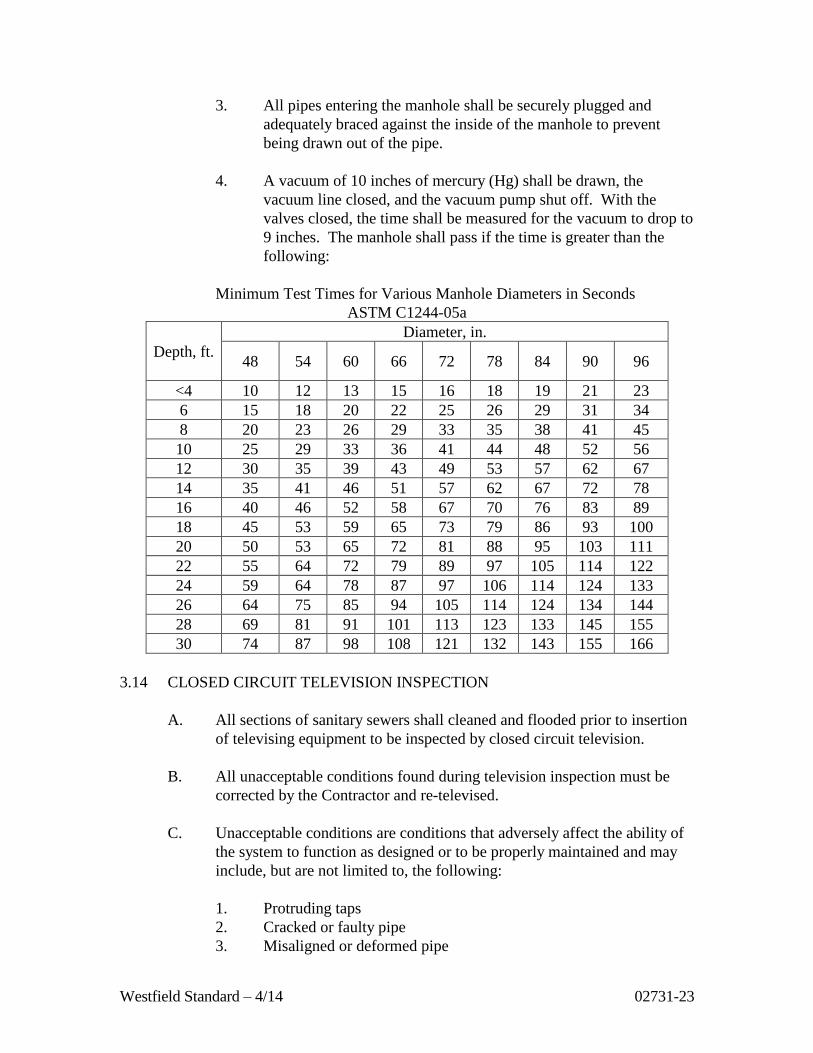
4. A vacuum of 10 inches of mercury (Hg) shall be drawn, the
vacuum line closed, and the vacuum pump shut off. With the
valves closed, the time shall be measured for the vacuum to drop to
9 inches. The manhole shall pass if the time is greater than the
following:
Minimum Test Times for Various Manhole Diameters in Seconds
ASTM C1244-05a
Depth, ft.
Diameter, in.
48 54 60 66 72 78 84 90 96
<4 10 12 13 15 16 18 19 21 23
6 15 18 20 22 25 26 29 31 34
8 20 23 26 29 33 35 38 41 45
10 25 29 33 36 41 44 48 52 56
12 30 35 39 43 49 53 57 62 67
14 35 41 46 51 57 62 67 72 78
16 40 46 52 58 67 70 76 83 89
18 45 53 59 65 73 79 86 93 100
20 50 53 65 72 81 88 95 103 111
22 55 64 72 79 89 97 105 114 122
24 59 64 78 87 97 106 114 124 133
26 64 75 85 94 105 114 124 134 144
28 69 81 91 101 113 123 133 145 155
30 74 87 98 108 121 132 143 155 166
3.14 CLOSED CIRCUIT TELEVISION INSPECTION
A. All sections of sanitary sewers shall cleaned and flooded prior to insertion
of televising equipment to be inspected by closed circuit television.
B. All unacceptable conditions found during television inspection must be
corrected by the Contractor and re-televised.
C. Unacceptable conditions are conditions that adversely affect the ability of
the system to function as designed or to be properly maintained and may
include, but are not limited to, the following:
1. Protruding taps
2. Cracked or faulty pipe
3. Misaligned or deformed pipe
Westfield Standard – 4/14 02731-24
4. Debris in line
5. Infiltration / exfiltration
6. Excessive gaps at joints
7. Bellies or sags with a depth greater than or equal to 10% (or a
maximum of 1-1/2 inches) of pipe diameter and/or a length greater
than 25 feet.
D. See Specification Section 02750 Sewer Televising for procedures.
3.15 DIGITAL AS-BUILTS/RECORD DRAWINGS
A. The Developer shall prepare or be responsible for the preparation and
submittal of digital as-builts in state plane coordinates as described in
Section 01001, Article 1.14.
PART 4 - FIGURES
4.1 STANDARD DETAILS
Figure Description
S-1 Standard Sanitary Manhole Detail
S-2 Standard Sanitary Manhole Spacer Ring Detail
S-3 Standard Sanitary Manhole Frame and Cover Details
S-4 Force Main Discharge Detail
S-5 Sewer Pipe Bedding Details
S-6 Concrete Encasement Detail
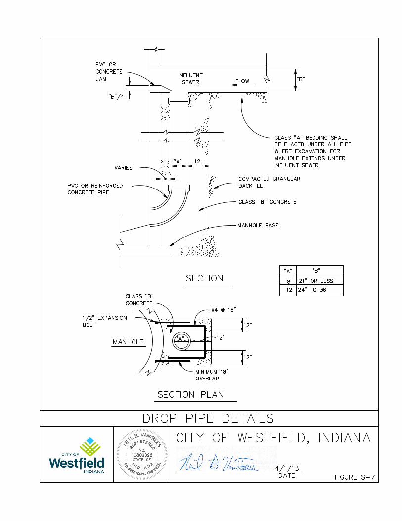
S-7 Drop Pipe Details
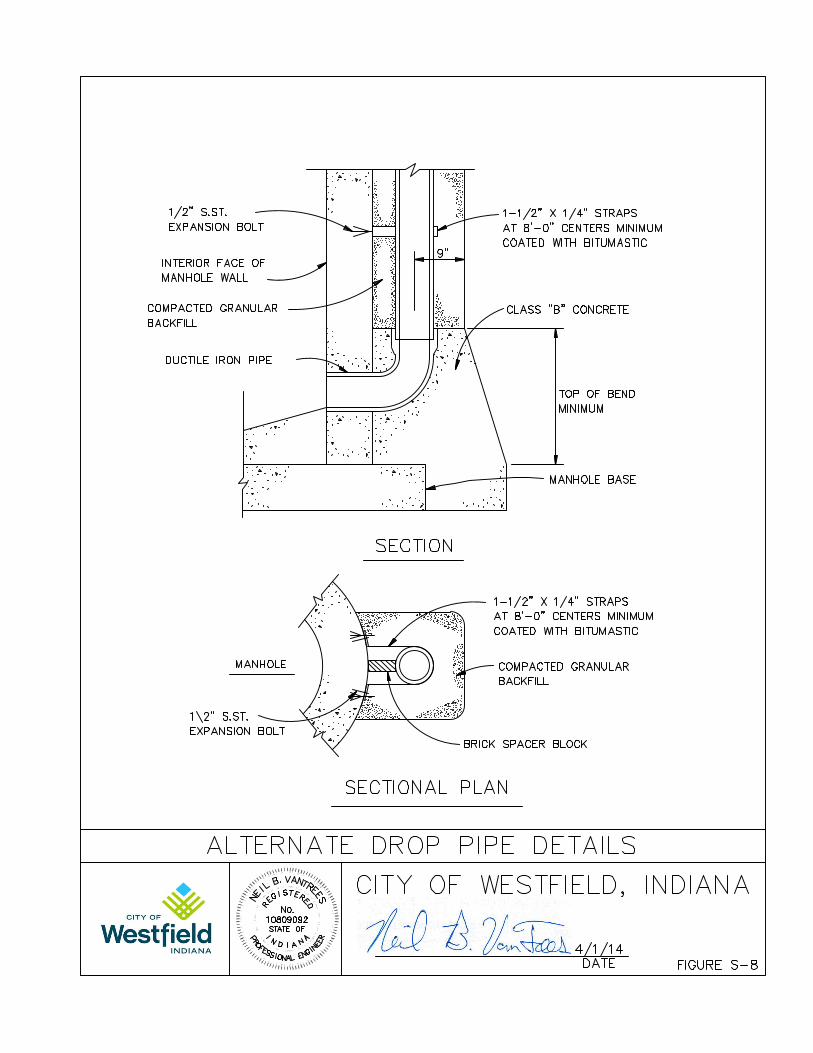
S-8 Alternate Drop Pipe Details
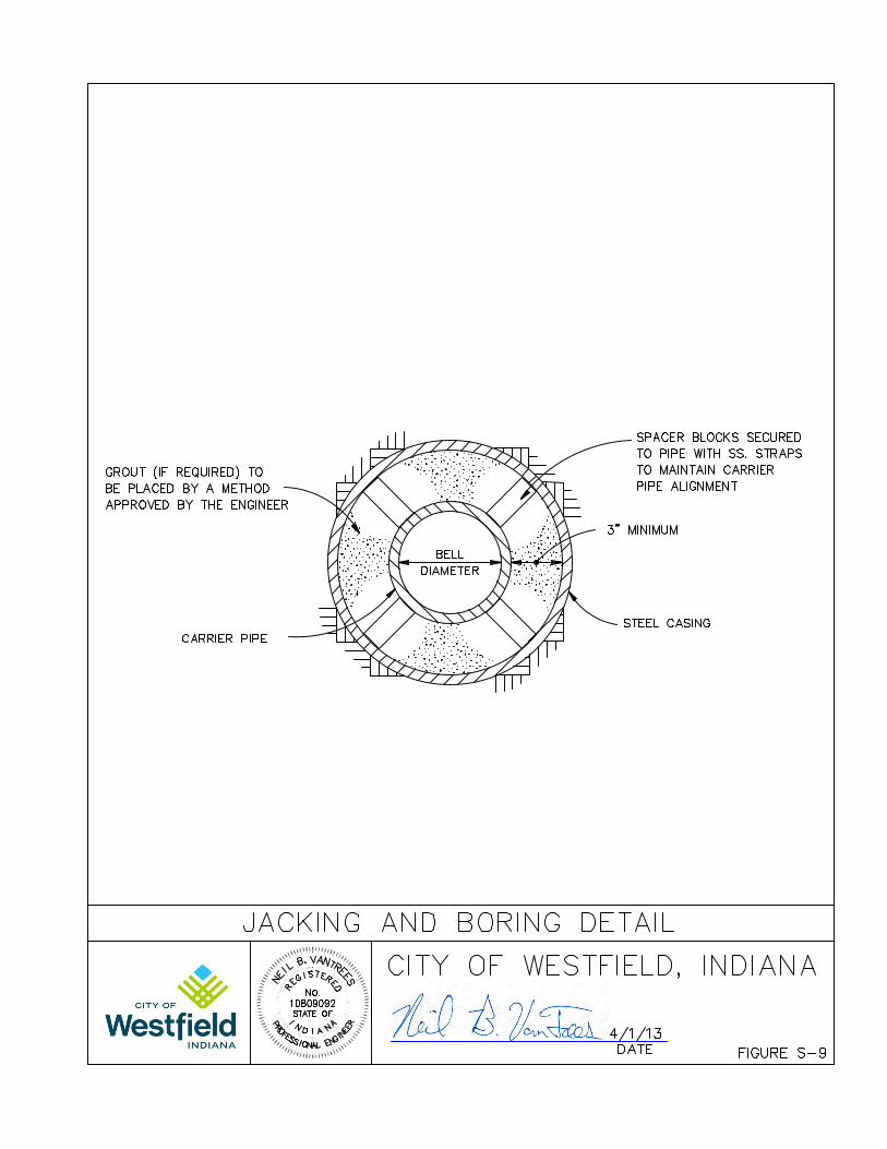
S-9 Jacking and Boring Detail
S-10 House/Building Service Connection Detail-1
S-11 House/Building Service Connection Detail-2
S-12 House/Building Service Bedding Detail
S-13 House/Building Service Clean-out/Check Valve Detail
S-14 Grease Trap Detail
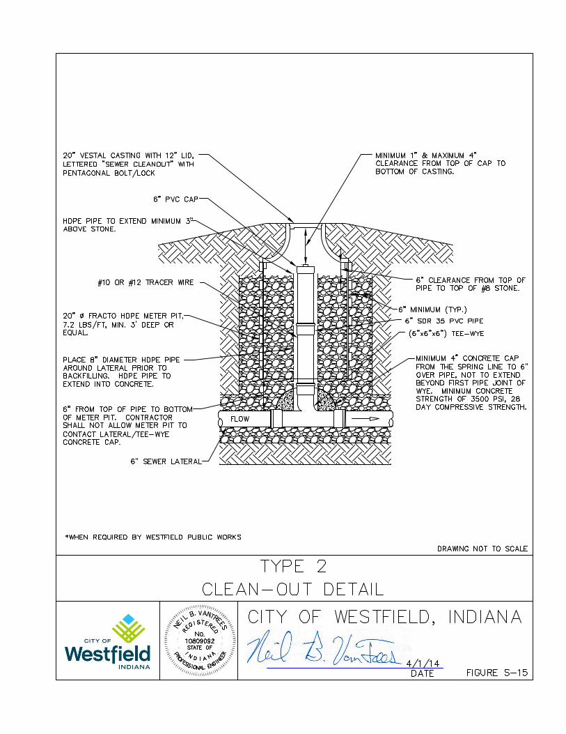
S-15 Type 2 Clean-out Detail
S-16 Closed Bottom Air/Vacuum Release Manhole Detail
END OF SECTION 02731


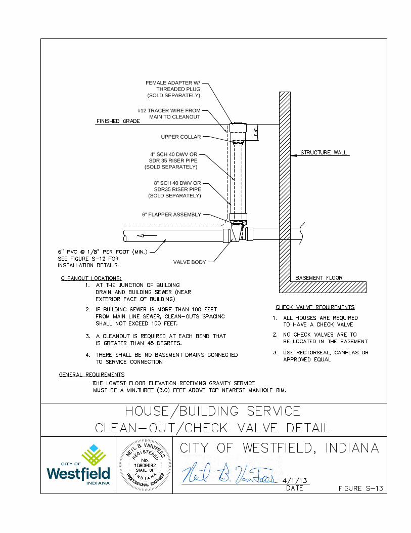
#12 TRACER WIRE FROM
MAIN TO CLEANOUT
FEMALE ADAPTER W/
THREADED PLUG
(SOLD SEPARATELY)
8" SCH 40 DWV OR
SDR35 RISER PIPE
(SOLD SEPARATELY)
VALVE BODY
4" SCH 40 DWV OR
SDR 35 RISER PIPE
(SOLD SEPARATELY)
6" FLAPPER ASSEMBLY
UPPER COLLAR