SECTION 01 EPISODE 1 THE TUFFEST STUFF CT REGISTRY … · SECTION 01, EPISODE 1 SECTION 01 EPISODE...
22
THE COMPUTED TOMOGRAPHY IMAGING CHAIN MAJOR COMPONENTS & THEIR FUNCTION SECTION 01, EPISODE 1 SECTION 01 EPISODE 1 THE TUFFEST STUFF CT REGISTRY REVIEW SEMINAR SOLUTION
Transcript of SECTION 01 EPISODE 1 THE TUFFEST STUFF CT REGISTRY … · SECTION 01, EPISODE 1 SECTION 01 EPISODE...
THE COMPUTED TOMOGRAPHY IMAGING CHAIN
MAJOR COMPONENTS & THEIR FUNCTION
SECTION 01, EPISODE 1
SECTION 01EPISODE 1
THE TUFFEST STUFF CT REGISTRY REVIEW SEMINAR SOLUTION

MAJOR COMPONENTSof
The CT IMAGING CHAIN
X-ray Tube (1.)
The Generator (2.)
The Beam Shaping Filter (3.)
Pre-patient Collimator (4.)
PATIENT
Pre-Detector Collimator (5.)
Detector Array (6.)
Analog-to-Digital Converter (7.)
CT Computer, aka, Array Processor (8.)
Digital-to-Analog Converter (9.)
Monitor (10.)
SECTION 01, EPISODE 1 2
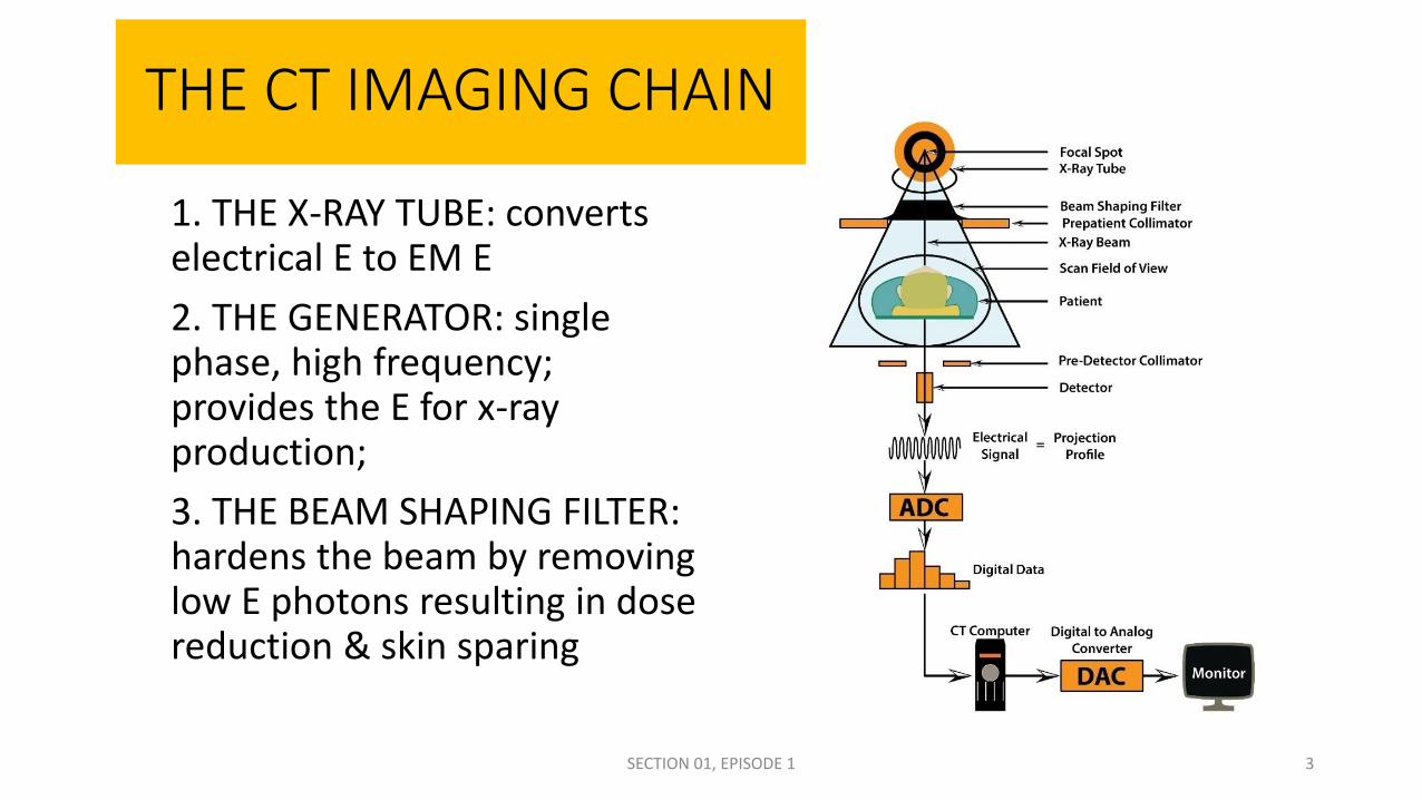
THE CT IMAGING CHAIN
1. THE X-RAY TUBE: converts electrical E to EM E
2. THE GENERATOR: single phase, high frequency; provides the E for x-ray production;
3. THE BEAM SHAPING FILTER: hardens the beam by removing low E photons resulting in dose reduction & skin sparing
SECTION 01, EPISODE 1 3

THE CT IMAGING CHAIN
4. PRE-PATIENT COLLIMATOR: controls the SCAN FIELD OF VIEW which is the field size on the patient; also assists in the determination of slice thickness
5. PRE-DETECTOR COLLIMATOR: controls BEAM WIDTH at the detector array by controlling the volume of the CONE BEAM
• BEAM WIDTH = SLICE THICKNESS X THE NUMBER OF DETECTORS UTILIZED
SECTION 01, EPISODE 1 4

THE CT IMAGING CHAIN
6. DETECTOR ARRAY: converts the EM E of the EXIT BEAM into electrical E impulses that represent the RADIOLOGIC IMAGE7. ANALOG TO DIGITAL CONVERTER (ADC): Samples, Quantifies & Codes the electrical E converting it to binary data 8. CT COMPUTER or ARRAY PROCESSOR: reconstructs binary data via application of various algorithms; the resultant CT NUMBERS are plotted on a matrix through the application of Filtered Back Projection
SECTION 01, EPISODE 1 5

The CT IMAGING CHAIN
SECTION 01, EPISODE 1
9. DAC (DIGITAL TO ANALOG CONVERTER): converts the reconstructed binary data back into electrical E impulses that are recognized by a display device
10. MONITOR: displays the electrical E impulses as an image of individual pixel gray shades representing the image proper.
(9.)
(10.)
6

The CT Imaging Process
• The process of CT image creation can be broken down into three general segments:
1.Data acquisition- provided by the Helical scanner
2.Image reconstruction-provided by the CT computer, aka, the Array Processor
3.Image display- provided by the monitor
SECTION 01, EPISODE 1 7

The visual CT Imaging Chain1. EM radiation from the x-ray tube
interacts with the patient’s body. Through the process of attenuation the interacting beam is modified to represent the anatomical structures with which interactions took place
2. The resultant, invisible photon pattern, that is the Radiologic Image, exits the patient and interacts with the detectors
SECTION 01, EPISODE 1
Radiologic Image = Remnant Radiation = Exit Beam
8

The visual CT Imaging Chain
3. At the detectors, the exit beam is captured and converted to electrical pulses consistent with the intensities of the photon pattern that represented the Radiologic Image and possessed within the exit beam
SECTION 01, EPISODE 1
Radiologic Image = Remnant Radiation = Exit Beam
9

The visual CT Imaging Chain4. The electrical pulses that now
represent the radiologic image are sent to the analog to digital converter (ADC)
5. In the ADC, those electrical impulses are sampled, quantified and coded resulting in their conversion to binary data
SECTION 01, EPISODE 1 10

The visual CT Imaging Chain
6. The binary data from the ADC are sent to the CT Computer, aka, Array Processor where various algorithms are applied in the process of reconstruction. It is here that the binary data are reconstructed and converted to CT NUMBERS. By way of filtered back projection the CT NUMBERS that represent individual shades of gray are then plotted onto a matrix.
SECTION 01, EPISODE 1 11

The visual CT Imaging Chain7. To see a CT image on a
monitor, the CT Number data is converted back to electrical impulses by the Digital to Analog Converter (DAC). These electrical impulses that still represent attenuation data are represented as various shades of gray as visualized on the monitor as an array of pixel gray shades.
SECTION 01, EPISODE 1 12

The ability of a tissue to attenuate the beam will ultimately result in a distinctive shade of gray…..
• THE DETECTOR SYSTEM FUNCTIONS INCLUDE THE CONVERSION OF ELECTROMAGNETIC ENERGY TO ELECTRICAL ENERGY
• AT THE ADC, THE ELECTRICAL IMPULSES ARE SAMPLED, QUANTIFIED AND CODED• THE END RESULT IS THE ASSIGNMENT OF A BINARY DIGIT TO THE
CODED SAMPLES• This coded binary digit will ultimately be associated with a shade of gray and
also a particular number that is appropriately scaled depending on the attenuation
SECTION 01, EPISODE 1
0 – 1 – 0 – 1 – 0 – 1 – 0 – 1 = Binary digit13

The ability of a tissue to attenuate the beam will ultimately result in a distinctive shade of gray…..
• DATA IN THE FORM OF BINARY DIGITS IS EXACTLY WHAT THE CT COMPUTER (ARRAY PROCESSOR) NEEDS TO RECONSTRUCT THE BINARY DATA INTO AN ORGANIZED PATTERN ON A MATRIX ACCORDING TO THE RECONSTRUCTION ALGORITHM
SECTION 01, EPISODE 1 14

WITHIN THE ADC…
• ELECTRICAL IMPULSES ARE SAMPLED• Individual samples have volt & amp characteristics
• Microvolts & picoamps
• SAMPLES ARE QUANTIFIED• Volt & amp characteristics are individual
• THE SAMPLE IS CODED• A binary digit is assigned• 1-0-1-0-1-0-1-0 = X• 0-1-1-0-1-0-1-0 = Y
SECTION 01, EPISODE 1 15

THE CT IMAGE
• MATRIX OF PIXELS with their assigned CT NUMBER• EACH PIXEL IS REPRESENTED BY A CT NUMBER THAT HAS AN ASSIGNED
SHADE OF GRAY• 256 POSSIBILITIES based on an 8 bit CT Computer system
• 4096 POSSIBILITIES based on a 12 bit CT Computer system
• 16,384 POSSIBILITIES based on a 14 bit CT Computer system
• VISUAL IMAGE IS COMPOSED OF GRAY SHADES CONSISTENT WITH THEIR CT NUMBER• BASED ON WINDOW LEVEL & WINDOW WIDTH
• ATTENUATION DATA IS STORED WITHIN THE VOXEL• EACH PIXEL IS THE FACE OF THE VOXEL
SECTION 01, EPISODE 1 16

CT NUMBER ACCURACY
• TESTING for LINEARITY• TO WHAT DEGREE DOES THE DERIVED CT NUMBER MATCH THE ATTENUATION
COEFFICIENT OF THE STRUCTURE IRRADIATED?
• ON THE OTHER HAND…
• TESTING for UNIFORMITY IS TESTING FOR SYSTEM SENSITIVITY or CONTRAST RESOLUTION• EXPOSURE EXPERIMENT involving phantom exposure and ROI Analysis of five
separate ROI areas• HU VALUES SHOULD BE WITHIN 2 HU OF ONE ANOTHER
SECTION 01, EPISODE 1 17

DEFINING NOISE
USING THE “BELL CURVE” DISCUSSION on INTELLIGENCE QUOTIENT (IQ) to EXPLAIN SIGNAL to NOISE RATIO
SECTION 01, EPISODE 1
-SCATTER-BEAM HARDENING-ELECTRONIC FLUCTUATIONS
18
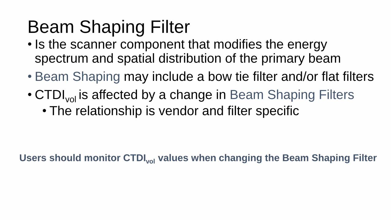
Beam Shaping Filter• Is the scanner component that modifies the energy
spectrum and spatial distribution of the primary beam
• Beam Shaping may include a bow tie filter and/or flat filters
• CTDIvol is affected by a change in Beam Shaping Filters
• The relationship is vendor and filter specific
Users should monitor CTDIvol values when changing the Beam Shaping Filter

Organ-Based Tube Current Modulation
• Is an AEC feature that allows for the tube current to be decreased or turned off over radiosensitive organs on the patient periphery, such as the breasts or eye lenses
• To maintain image quality, tube current may need to be increased at other view angles
The use of Organ-Based Tube Current Modulation may reduce the absorbed dose to organs at the surface of the
body but may increase the absorbed dose to other organs

Things to study…1. Know the CT Imaging chain backwards and forwards
1. Know the location & function of each component compared to the other components in the CT Imaging Chain
1. Ie. The Detector system is located after the Pre-detector collimator and before the ADC. The detector system primary function is the conversion of EM E to electrical impulses
2. What is a binary digit? From where does it come?1. Binary digits are the end result of the Sampling, Quantifying and Coding activities
that occur in the ADC
3. What do we get when we evaluate the CT system for:1. Linearity: to what degree does the derived CT Number match the attenuation
coefficient of the structure irradiated?
2. Uniformity: System Sensitivity regarding contrast resolution1. Phantom exposures and ROI analysis resulting in 5 analyses all within 2 HU of each other
SECTION 01, EPISODE 1 21

Things to study…
4. To assist with your study of the CT Imaging Chain complete the downloadable worksheet designed for this purpose
5. NOISE sources include the following:
a. Scatter radiation
b. Beam Hardening
c. Electronic fluctuations
6. What is the primary function of the Beam Shaping Filter?
7. What is Organ-based Tube Current Modulation?
SECTION 01, EPISODE 1 22