SECTION 00901 ADDENDUM NO. 1 LOCKWOOD,...
47
160-10604-002 00901-1 Addendum No. 1 City of Copperas Cove Northwest WWTP Improvements Phase Two SECTION 00901 ADDENDUM NO. 1 LOCKWOOD, ANDREWS & NEWNAM, INC. 215 Mary Street, Suite 305 Waco, Texas 76701 Phone: (254) 753-9585 Fax: (254) 753-9593 TO: Prospective Bidders This Addendum forms a part of the Contract Documents and modifies the original Bidding Documents. Acknowledge receipt of this Addendum in the space provided on the Bid Form. Failure to do so may subject Bidder to disqualification. MISCELLANEOUS 1. Response to questions: Q.1. Confirm the Design Running Torque is 12000 ft-lbs. Yes-The Design Running Torque is 12000 ft-lbs. No other design torques will be considered. Q.2. What is the influent pipe size and elevation? Contractor to confirm all existing dimensions. Q.3. Confirm the need for dual skimmers. Yes-Dual skimmers will be utilized. No substitutions will be considered. Q.4. What are the sizes of the effluent troughs? Contractor to confirm all existing dimensions. Q.5. Does the walkway go to just the center or all the way across the tank? The walkway spans across the entire diameter of the tank. Q.6. Is the walkway hot dip galvanized or painted? The walkway is hot dip galvanized. No painting is required. PLANS 2. Add note to Sheets D-111, D-112, D-311, & D-312: “2. REUSE EXISTING EFFLUENT LAUNDER, WEIR, AND DROP BOX.” 3. Revise Keyed Note 1 on Sheet E-102: “… Provide Nema 4X SS 30A/3P/NF disconnects for each motor circuit INTEGRAL TO THE CONTROL PANEL. …” SPECIFICATIONS 4. Replace the following sections: a) Instructions to Bidders b) Bid Form c) 11345 – Thickener Mechanism
Transcript of SECTION 00901 ADDENDUM NO. 1 LOCKWOOD,...

160-10604-002 00901-1 Addendum No. 1
City of Copperas Cove
Northwest WWTP Improvements Phase Two
SECTION 00901
ADDENDUM NO. 1
LOCKWOOD, ANDREWS & NEWNAM, INC.
215 Mary Street, Suite 305
Waco, Texas 76701
Phone: (254) 753-9585
Fax: (254) 753-9593
TO: Prospective Bidders
This Addendum forms a part of the Contract Documents and modifies the original Bidding Documents.
Acknowledge receipt of this Addendum in the space provided on the Bid Form. Failure to do so may
subject Bidder to disqualification.
MISCELLANEOUS
1. Response to questions:
Q.1. Confirm the Design Running Torque is 12000 ft-lbs.
Yes-The Design Running Torque is 12000 ft-lbs. No other design torques will be considered.
Q.2. What is the influent pipe size and elevation?
Contractor to confirm all existing dimensions.
Q.3. Confirm the need for dual skimmers.
Yes-Dual skimmers will be utilized. No substitutions will be considered.
Q.4. What are the sizes of the effluent troughs?
Contractor to confirm all existing dimensions.
Q.5. Does the walkway go to just the center or all the way across the tank?
The walkway spans across the entire diameter of the tank.
Q.6. Is the walkway hot dip galvanized or painted?
The walkway is hot dip galvanized. No painting is required.
PLANS
2. Add note to Sheets D-111, D-112, D-311, & D-312:
“2. REUSE EXISTING EFFLUENT LAUNDER, WEIR, AND DROP BOX.”
3. Revise Keyed Note 1 on Sheet E-102:
“… Provide Nema 4X SS 30A/3P/NF disconnects for each motor circuit INTEGRAL TO
THE CONTROL PANEL. …”
SPECIFICATIONS
4. Replace the following sections:
a) Instructions to Bidders
b) Bid Form
c) 11345 – Thickener Mechanism

160-10604-002 00901-2 Addendum No. 1
5. Revise Form of Agreement
a. Revise Article 4.02:
“The work shall be substantially completed within 180 270 days after the date when the Contract
Times commence…”
6. Section 01110 – Summary of Work
a. Revise Item 1.2.L.1:
“Provide one (1) backup SHELF SPARE ALLEN-BRADLEY PLC for the existing Blower system
installed in Phase 1. Refer to Division 13 for PLC bill of materials and requirements.”
7. Section 11331 – Mechanically Cleaned Fine Bar Screens:
a. Revise Item 2.06.B.1.a:
“Control Panel(s) shall include a main, lockable, flange mounted disconnect. The panel shall be
constructed by a UL certified control panel build facility and shall be supported by the appropriate
UL 508A 698 labeling.”
b. Revise Item 2.06.B.3.a:
“Enclosure shall be NEMA 4X 316 SSTL 7/9 CAST ALUMINUM rated for Classified area
installation.”
8. Section 11333 – Washer Compactor:
a. Revise Item 2.04.A.2.e:
“Thrust Bearings. Shall be UHMW, DELRIN, OR EQUIVALENT, thrust type, self-lubricating and
be capable of withstanding 2000 lb of thrust load (each auger) at 2.2 RPM for life of machine.”
b. Revise Item 2.04.C.1.a:
“Controls shall be provided by Washer Compactor manufacturer and coordinated with continuous
cleaning mechanical bar screen controls. CONTROL PANEL IS TO BE COMBINED WITH BAR
SCREEN CONTROL PANEL. Refer to Section 11331.”
9. Section 13410 – Programmable Logic Controllers (PLC)
a. Revise Item 2.1.A:
“A. THE HEADWORKS AND THICKENER PLC SHALL BE UNITRONICS V350. All PLCs
THE SHELF SPARE PLC shall be Allen Bradley ControLogix or CompactLogix, PLC I/O modules
shall be selected within one I/O product family. No substitutions are allowed.”
b. Revise Item 2.2.A.1:
“Approved PLC manufacturers are: Allen Bradley CompactLogix Series, OR UNITRONICS.”
c. Revise Item 2.3.A.1:
“1. General Requirements. The following are the requirements for the SHELF SPARE PLC
programming software package.”
10. Section 13413 – Control Panels:
a. Revise Item 2.4.S:
“HMI. Provide Rockwell Automation Model 6181 panel mounted computer preloaded with
Windows 7 operating system and RS View HMI software for the DO control panel FOR THE
SHELF SPARE PLC. PROVIDE UNITRONICS V350 PLC WITH COLOR/TOUCH SCREEN
HMI FOR THE HEADWORKS AND THICKENER PLC.”

160-10604-002 00901-3 Addendum No. 1
ATTACHMENTS
11. Attachment 1: Revised Specifications
12. Attachment 2: Agenda and Sign-In Sheet from Pre-Bid
___________________________________
January 5, 2016
Approved by:
Daniel Dow, P.E.
Lockwood, Andrews & Newnam, Inc.
END OF SECTION


Attachment 1:
Revised Specifications


INSTRUCTIONS TO BIDDERS – Northwest WWTP Improvements Phase Two 1 of 9
INSTRUCTIONS TO BIDDERS Proposal
The Proposal (or copies of the proposal) shall be submitted on the bidding forms, which are included herein, and shall be enclosed in a sealed envelope addressed to: COPPERAS COVE FINANCE DEPARTMENT Attn: Tracy Molnes 914 South Main Street, Suite H Copperas Cove, Texas 76522 and shall be identified as follows: “BID 2016-01-84 for Northwest WWTP Improvements Phase Two, to be opened at 2:00 P.M., January 14th, 2016.” Any questions or requests for clarification must be submitted to the Finance Department, prior to 2:00 p.m. December 30th, 2015 via email to Tracy Molnes, [email protected] , subject line containing bid number and description. There will be no exceptions. All responses to the questions will be sent to all known bidders. Any requests received after this date and time will not be responded to.
1. DEFINED TERMS.
Terms used in these Instructions to BIDDERS which are defined in the General Conditions of the construction contract shall have the same meanings assigned to them in these Instructions to BIDDERS. The term "successful BIDDER" means the lowest, qualified, responsible and responsive BIDDER to whom OWNER (on the basis of OWNER's evaluation as hereinafter provided), makes an award. The term "bidding documents" includes the ADVERTISEMENT FOR BIDS, INSTRUCTIONS TO BIDDERS, the BID FORM and the proposed contract documents (including all addenda issued prior to receipt of bids).
2. COPIES OF BIDDING DOCUMENTS.
2.1. Complete sets of the Bidding Documents for the purchase sum as stated in the Invitation to Bid may be obtained from ARC Document Solutions. Partial sets will not be issued.
2.2 Complete sets of bidding documents must be used in preparing bids; neither
OWNER nor ENGINEER assume any responsibility for errors or misinterpretations resulting from the use of incomplete sets of bidding documents.
2.3 OWNER and ENGINEER in making copies of bidding documents available on
the above terms do so only for the purpose of obtaining bids on the work and do not confer a license or grant for any other use.

INSTRUCTIONS TO BIDDERS – Northwest WWTP Improvements Phase Two 2 of 9
3. EXPERIENCE RECORD AND FINANCIAL STATEMENT.
3.1 The Experience Record, included herein, shall be filled in showing completed jobs of a similar nature to the one covered by the bid and the work in progress with contract and bond amounts and percent of completion.
3.2 A sworn statement of the current financial condition of the BIDDER in order to
provide the OWNER with information relative to the responsibility of BIDDERS and their ability to finance and construct the work. The sworn financial statement shall include, but not be limited to the following:
A. List of all previous bankruptcies by the BIDDER or BIDDERS;
B. List all liens on the BIDDER or BIDDERS within the last twelve (12) months;
C. An indication of outstanding debt and the ability to finance the project; D. A summary of liabilities and assets of the company. This statement shall be enclosed with the Bid in a separate envelope labeled "Financial Statement". All but two (2) apparent low BIDDERS' financial statements will be returned to the BIDDER unopened with the return of his bid security. Other BIDDERS' financial statements will be returned to the BIDDER upon return of the bid security after execution of the Agreement.
4. EXAMINATION OF CONTRACT DOCUMENTS AND SITE.
4.1 It is the responsibility of each BIDDER before submitting a bid to (a) examine the contract documents thoroughly; (b) visit the site to become familiar with local conditions that may in any manner affect cost, progress or performance, or furnishing of the work; (c) consider federal, state, and local laws and regulations that may in any manner affect cost, progress or performance of the work; (d) study and carefully correlate BIDDER's observations with the contract documents; and (e) notify the ENGINEER of all conflicts, errors or discrepancies in the contract documents.
4.2 Information and data reflected in the contract documents with respect to
underground facilities at or contiguous to the site is based upon information and data furnished to OWNER and ENGINEER by owners of such underground facilities or others, and OWNER does not assume responsibility for the accuracy or completeness thereof unless it is expressly provided otherwise in the Supplementary Conditions.
4.3 Provisions concerning responsibilities for the adequacy of data furnished to
prospective BIDDERS on subsurface conditions, underground facilities and other physical conditions, and possible changes in the contract documents

INSTRUCTIONS TO BIDDERS – Northwest WWTP Improvements Phase Two 3 of 9
due to differing conditions appear in Paragraphs 4.2 and 4.3 of the General Conditions.
4.4 Before submitting a bid, each BIDDER will be responsible to make or obtain
such explorations, tests and data concerning physical conditions (surface, and underground facilities) at or contiguous to the site, or otherwise which may affect cost, progress, performance or furnishing of the work and which BIDDER deems necessary to determine its bid for performing and furnishing the work in accordance with the time, price and other terms and conditions of the contract documents.
4.5 On request in advance, OWNER will provide each BIDDER access to the site
to conduct such explorations and tests as each BIDDER deems necessary for submission of a bid. BIDDER shall fill in all holes, clean up and restore the site to its former condition upon completion of such explorations. Explorations and tests are the financial responsibility of BIDDER.
4.6 The lands upon which the work is to be performed, rights-of-way for access
thereto and other lands designated for use by CONTRACTOR in performing the work are identified in the contract documents. All additional lands and access thereto required for temporary construction facilities or storage of materials and equipment are to be provided by CONTRACTOR. He shall use barricades, lights, etc. and sufficient protection to assure the safety of the public.
4.7 The submission of a bid will constitute an incontrovertible representation by
the BIDDER that BIDDER has complied with every requirement of this Article, that without exception the bid is premised upon performing and furnishing the work required by the contract documents, and such means, methods, techniques, sequences or procedure of construction as may be indicated in or required by the contract documents, and that the contract documents are sufficient in scope and detail to indicate and convey understanding of all terms and conditions for performance of the work.
5. INTERPRETATIONS AND ADDENDA.
5.1 All questions about the meaning or intent of the contract documents shall be directed to ENGINEER. Interpretations or clarifications considered necessary by ENGINEER in response to such questions will be issued by addenda mailed or delivered to all parties recorded by ENGINEER as having received the bidding documents. Questions received less than seven (7) days prior to the date for opening of bids may not be answered. Only questions answered by formal writing will be binding. Oral and other interpretations or clarifications will be without legal effect.
5.2 Addenda may also be issued to modify the bidding documents as deemed
advisable by OWNER or ENGINEER.

INSTRUCTIONS TO BIDDERS – Northwest WWTP Improvements Phase Two 4 of 9
6. BID SECURITY.
6.1 Each bid must be accompanied by bid security made payable to the OWNER, in an amount of five percent (5%) of the BIDDER's maximum bid price and in the form of a Bid Bond issued by an acceptable surety, cashier's check, or certified check.
6.2 The bid security of the successful BIDDER will be retained until such BIDDER
has executed the Agreement and furnished the required contract security, whereupon it will be returned. If the successful BIDDER fails to execute and deliver the Agreement and furnish the required contract security within ten (10) business days of the Notice of Award, OWNER may annul the Notice of Award and the bid security of that BIDDER will be forfeited. The Bid Security of other BIDDERS whom OWNER believes to have a reasonable chance of receiving the award may be retained by OWNER until the earlier of the seventh (7th) day after effective date of the Agreement or the thirtieth (30th) day after the bid opening, whereupon bid security furnished by such BIDDERS will be returned. Bid security with bids which are not competitive will be returned within seven (7) days after the bid opening.
7. CONTRACT TIME.
The number of days within which, or the date by which, the work is to be substantially completed and also completed and ready for final payment (the contract time) are on the Bid Form.
8. LIQUIDATED DAMAGES.
Provisions for liquidated damages, if any, are set forth in the Agreement. 9. SUBSTITUTE AND "OR EQUAL" ITEMS.
The Contract, if awarded, will be on the basis of material and equipment described in the drawings or specified in the specifications without consideration of possible substitute or "or-equal" items. Whenever it is indicated in the drawings or specified in the specification that a substitute or "or-equal" item of material or equipment may be furnished or used by CONTRACTOR if acceptable to ENGINEER, application for such acceptance will not be considered by ENGINEER until after the effective date in the Agreement. The procedure for submittal of any such application by CONTRACTOR and consideration by ENGINEER is set forth in paragraphs 6.7.1, 6.7.2 and 6.7.3 of the General Conditions which may be supplemented in the Supplementary Conditions.
10. SUBCONTRACTORS, SUPPLIERS AND OTHERS.

INSTRUCTIONS TO BIDDERS – Northwest WWTP Improvements Phase Two 5 of 9
The BIDDER must submit with the bid a list of any and all subcontractors to which it is proposed to subcontract 25% or more of the total bid amount. The identification is to be made in the form contained in these contract documents. For each subcontractor so identified, a separate Experience Record and Financial Statement must be submitted if requested by the ENGINEER.
If OWNER or ENGINEER, after due investigation, has reasonable objection to subcontractors so identified, they may, before the Notice of Award is given, request the apparent successful BIDDER to submit an acceptable substitute without an increase in bid price.
If apparent successful BIDDER declines to make any such substitution, OWNER may award the contract to the next lowest BIDDER that proposes to use acceptable subcontractors, suppliers and other persons and organizations. The declining to make requested substitutions will not constitute grounds for sacrificing the bid security of any BIDDER. Any subcontractor, supplier, other person or organization listed and to whom OWNER or ENGINEER does not make written objection prior to the giving of the Notice of Award will be deemed acceptable to OWNER and ENGINEER subject to revocation of such acceptance after the effective date of the Agreement as provided in Paragraphs 6.8.2 of the General Conditions.
Other proposed subcontractors and suppliers will be subject to approval by the OWNER and ENGINEER after the effective date of the Agreement.
11. BID FORM.
11.1 The Bid Form is included with the bidding documents; additional copies may be obtained from Engineer.
11.2 Bid Forms must be completed in ink or by typewriter. The unit price bid for
each item on the form must be stated in words and numerals; in each case of a conflict, words will take precedence.
11.3 Bids by corporations must be executed in the corporate name by the
president or a vice-president (or other corporate officer accompanied by evidence of authority to sign) and the corporate seal must be affixed and attested by the secretary or an assistant secretary. The corporate address and state of incorporation shall be shown below the signature.
11.4 Bids by partnerships must be executed in the partnership name and signed
by a partner, whose title must appear under the signature and the official address of the partnership must be shown below the signature.
11.5 All names must be typed or printed below the signature.
INSTRUCTIONS TO BIDDERS – Northwest WWTP Improvements Phase Two 6 of 9
11.6 The bid shall contain an acknowledgment of receipt of all addenda (the numbers of which shall be filled in on the Bid Form).
11.7 The address and telephone number for communications regarding the bid
must be shown. 11.8 Current Texas state law prohibits amendment, alteration or change of bids
after opening for the purpose of correcting errors. BE CAREFUL in preparing your bid. If errors occur, your bid may be subject to rejection because of the error, or you may be required to contract based upon the uncorrected error.
12. SUBMISSION OF BIDS.
Bids shall be submitted at the time and place indicated in the ADVERTISEMENT FOR BIDS and shall be included in an opaque sealed envelope, marked with the project title and name and address of the BIDDER and accompanied by the bid security and other required documents. If the bid is sent through the mail or other delivery system, the sealed envelope shall be enclosed in a separate envelope with the notation "BID ENCLOSED" on the face thereof.
Bids received after the deadline shall be considered void and unacceptable and will be returned to the bidder unopened.
13. MODIFICATION AND WITHDRAWAL OF BIDS.
Bids may be modified or withdrawn by an appropriate document duly executed (in the manner that a bid must be executed) and delivered to the place where bids are to be submitted at any time prior to the opening of bids.
14. OPENING OF BIDS.
Bids will be read aloud publicly. An abstract of the amounts of the base bids and major alternates (if any) will be made available to BIDDERS after the opening of bids. Unit price amounts shall remain confidential until after award of the bid.
15. BIDS TO REMAIN OPEN.
All bids shall remain subject to acceptance for ninety (90) days after the day of the bid opening, but OWNER may, in its sole discretion, release any bid and return the bid security prior to that date.
16. AWARD OF CONTRACT.
16.1 AWARD WILL BE BASED ON THE LUMP SUM TOTAL OF ALL SPECIFIED EQUIPMENT, ALTERNATES WILL NOT BE CONSIDERED UNTIL AFTER THE AWARD.

INSTRUCTIONS TO BIDDERS – Northwest WWTP Improvements Phase Two 7 of 9
16.2 OWNER reserves the right to reject any and all bids, to waive any and all informalities not involving price, time or changes in the work and to negotiate contract terms with the successful BIDDER, and the right to disregard all non-conforming, non-responsive, unbalanced or conditional bids. Also, OWNER reserves the right to reject the bid of any BIDDER if OWNER believes that it would not be in the best interest of the project to make an award to that BIDDER, whether because the bid is not responsive or the BIDDER is unqualified or of doubtful financial ability or fails to meet any other pertinent standard or criteria established by OWNER.
16.3 In evaluating bids, OWNER will consider the qualifications of the BIDDERS,
whether or not the bids comply with the prescribed requirements, and such alternates, unit prices, contract time, and other data, as may be requested in the Bid Form or prior to the Notice of Award.
16.4 OWNER may consider the qualifications and experience of subcontractors,
suppliers, and other persons and organizations proposed for those portions of the work as to which the identity of subcontractors, suppliers, and other persons or organizations must be submitted as provided in the Supplementary Conditions. OWNER may consider the operating costs, maintenance requirements, performance data and guarantees of major items of materials and equipment proposed for incorporation in the work when such data is required to be submitted prior to the Notice of Award.
16.5 OWNER may conduct such investigations as it deems necessary to assist in
the evaluation of any bid and to establish the responsibility, qualifications and financial ability of BIDDERS, proposed subcontractors, suppliers and other persons and organizations to do the work in accordance with the contract documents to OWNER'S satisfaction within the prescribed time.
16.6 The OWNER reserves the right to reject the bid of any BIDDER who does not
pass any such evaluation to OWNER'S satisfaction. 16.7 The OWNER may also reject any bid which is considered irregular.
Examples of irregularities include the following:
A. If the Bid Form provided herein is not used by or is altered by the BIDDER;
B. If there are any unauthorized additions or conditional bids, or
irregularities of any kind which may tend to make the bid incomplete, indefinite, or ambiguous as to its meaning;
C. If the BIDDER adds any provisions reserving the right to accept or reject
any award, or to enter into a contract pursuant to an award;

INSTRUCTIONS TO BIDDERS – Northwest WWTP Improvements Phase Two 8 of 9
D. If, in the opinion of the ENGINEER, the unit or lump sum prices contained in the bid are obviously unbalanced (where the prices of certain items have been made substantially greater or less than reasonable values);
16.8 BASE BID shall be a Unit Price Bid and shall include all work shown on the
Drawing or called out in the Specifications. unless specifically noted an alternate or furnished and installed by others.
16.9 The contractor is not required to bid on the Base Bid item(s). if the
contractor chooses to bid on the Alternate Bid item(s) only. The Owner reserves the right to award a bid for an Alternate Bid Item to an individual contractor as stated in 16.10. The Owner reserves the right to consider alternates after the award of the bid.
16.10 The contractor shall provide an equipment list of manufacturers with their
bid. Contractors submitting ambiguous and/or incomplete lists will be eliminated. Alternate manufacturers or non-prequalified manufacturers will be eliminated from consideration.
16.11The Owner reserves the right to award bids on the lump sum or unit price
basis, whichever is in the best interest of the Owner. The Owner reserves the right to split the bid between bidders based on individual prices or the Owner may award a bid to a single contractor/bidder or multiple contractors. The Owner also reserves the right to award the bid to either the lowest responsible bidder or to the bidder who provides goods or services at the best value for the City. Bids shall be valid for a period of ninety (90) days after Owner reserves the right. The Owner reserves the right to pick and choose any option that is in the best interest of the City. This includes the alternate bids items.
17. CONTRACT SECURITIES.
Paragraph 5.1 of the General Conditions and the Supplementary Conditions set forth OWNER'S requirements as to Performance and Payment Bonds. When the successful BIDDER delivers the executed agreement to OWNER it must be accompanied by the required Performance and Payment Bonds. BIDDER must submit bonds on forms provided in the contract documents.
18. SIGNING OF AGREEMENT.
When OWNER gives a Notice of Award to the successful BIDDER, it will be accompanied by the required number of unsigned counterparts of the agreement and all other written contract documents attached. Within ten business days thereafter, CONTRACTOR shall sign and deliver the required number of counterparts of the agreement and attached documents to OWNER with the

INSTRUCTIONS TO BIDDERS – Northwest WWTP Improvements Phase Two 9 of 9
required bonds. Thereafter, OWNER shall deliver one fully signed counterpart to CONTRACTOR.


BID FORM – Northwest WWTP Improvements Phase Two 1 of 9
BID FORM
Bidding Firm:
Address:
City:
State, Zip:
PROJECT IDENTIFICATION: Northwest WWTP Improvements Phase Two BID NO. 2016-01-84 CITY OF COPPERAS COVE, TEXAS
THIS BID IS SUBMITTED TO: COPPERAS COVE CITY HALL FINANCE DEPARTMENT ATTN: TRACY MOLNES 914 SOUTH MAIN STREET P.O. BOX 1449 COPPERAS COVE, TEXAS 76522
A. The undersigned BIDDER proposes and agrees, if this Bid is accepted, to enter into an Agreement with OWNER, in the form included in the Contract Documents, to complete all Work as specified or indicated in the Contract Documents for the Contract Price, and within the Contract Time indicated in the Bid and in accordance with the Contract Documents.
B. BIDDER accepts all of the terms and conditions of the Instruction to Bidders, including without limitation those dealing with the disposition of Bid Security. This Bid will remain open for ninety (90) days after the day of Bid opening. BIDDER will sign the Agreement and submit the Contract Security and other documents required by the Contract Documents within ten business days after the date of OWNER's Notice of Award.
C. In submitting this Bid, BIDDER represents, as more fully set forth in the Agreement, that:
1. Bidder has examined copies of all the Contract Documents and of thefollowing addenda, receipt of which is hereby acknowledged, and also copiesof the Advertisement for Bids and the Instructions to Bidders.
Matous Construction, Ltd.
8602 North Highway 317
Belton
Tx, 76513
BID FORM – Northwest WWTP Improvements Phase Two 2 of 9
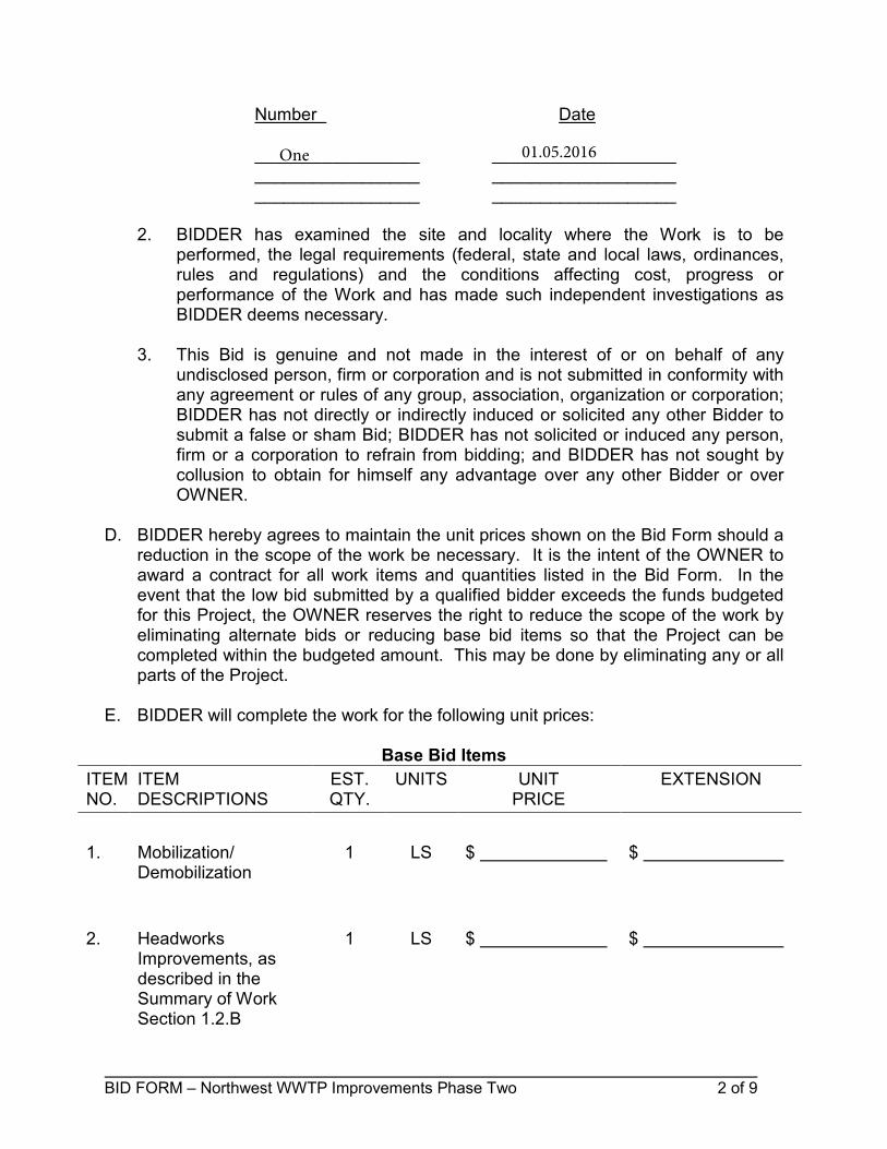
Number Date
_________________ ___________________ _________________ ___________________ _________________ ___________________
2. BIDDER has examined the site and locality where the Work is to beperformed, the legal requirements (federal, state and local laws, ordinances,rules and regulations) and the conditions affecting cost, progress orperformance of the Work and has made such independent investigations asBIDDER deems necessary.
3. This Bid is genuine and not made in the interest of or on behalf of anyundisclosed person, firm or corporation and is not submitted in conformity withany agreement or rules of any group, association, organization or corporation;BIDDER has not directly or indirectly induced or solicited any other Bidder tosubmit a false or sham Bid; BIDDER has not solicited or induced any person,firm or a corporation to refrain from bidding; and BIDDER has not sought bycollusion to obtain for himself any advantage over any other Bidder or overOWNER.
D. BIDDER hereby agrees to maintain the unit prices shown on the Bid Form should a reduction in the scope of the work be necessary. It is the intent of the OWNER to award a contract for all work items and quantities listed in the Bid Form. In the event that the low bid submitted by a qualified bidder exceeds the funds budgeted for this Project, the OWNER reserves the right to reduce the scope of the work by eliminating alternate bids or reducing base bid items so that the Project can be completed within the budgeted amount. This may be done by eliminating any or all parts of the Project.
E. BIDDER will complete the work for the following unit prices:
Base Bid Items
ITEM NO.
ITEM DESCRIPTIONS
EST. QTY.
UNITS UNIT PRICE
EXTENSION
1. Mobilization/Demobilization
1 LS $ $
2. HeadworksImprovements, asdescribed in theSummary of WorkSection 1.2.B
1 LS $ $
One 01.05.2016

BID FORM – Northwest WWTP Improvements Phase Two 3 of 9
ITEM NO.
ITEM DESCRIPTIONS
EST. QTY.
UNITS UNIT PRICE
EXTENSION
3. ThickenerImprovements, asdescribed in theSummary of WorkSection 1.2.C
1 LS $ $
4. A.C. Unit, asdescribed in theSummary of WorkSection 1.2.D
1 LS $ $
5. Sump Pumps, asdescribed in theSummary of WorkSection 1.2.E
1 LS $ $
6. Fire Hoses, asdescribed in theSummary of WorkSection 1.2.F
1 LS $ $
7. Solenoid, asdescribed in theSummary of WorkSection 1.2.G
1 LS $ $
8. Verbatim Unit, asdescribed in theSummary of WorkSection 1.2.H
1 LS $ $
9. Bay Heater, asdescribed in theSummary of WorkSection 1.2.I
1 LS $ $
10. Front Door, asdescribed in theSummary of WorkSection 1.2.J
1 LS $ $

BID FORM – Northwest WWTP Improvements Phase Two 4 of 9
ITEM NO.
ITEM DESCRIPTIONS
EST. QTY.
UNITS UNIT PRICE
EXTENSION
11. Polymer FeedSystem, as describedin the Summary ofWork Section 1.2.K
1 LS $ $
12. Allen-Bradley Shelf-Spare PLC System,as described in theSummary of WorkSection 1.2.K
1 LS $ _____________ $ ______________
Lump Sum Bid in Words: __
Total Lump Sum Base Bid: $
Allowances: $ Refer to Allowances as per Section 01210
Total Lump Sum Bid: $
F. BIDDER agrees that the Work covered by the Base Bid will be substantially completed within 180 270 calendar days after the date the Contract Time commences to run. Bidder accepts the provisions of the agreement as to liquidated damages in the event of failure to complete the Work on time.
G. The following documents are attached to and made a Condition of this Bid:
1. Required Bid Security in the form of a Bid Bond issued by anacceptable surety, certified check, or cashier's check.
2. Financial Statement enclosed in a separate sealed envelope.
3. A tabulation of Subcontractors and organizations required to beidentified in this Bid.
4. Experience record as indicated on this Bid Form.
H. Communications concerning this Bid shall be delivered to the address of bidder indicated below.

BID FORM – Northwest WWTP Improvements Phase Two 5 of 9
I. The terms in this Bid which are defined in the General Conditions of the Construction Contract included as part of the Contract Documents have the meanings assigned to them in the General Conditions.
SUBMITTED ON , 2015.
If BIDDER is:
An Individual By: (SEAL)
(Individual's Name)
Doing business as:
Business address:
Telephone No: A Partnership By: (SEAL)
(Firm Name)
(General Partner)
Business address: ______
Telephone No:
A Corporation By: (CORPORATE SEAL)
(Corporation Name)
January 14, 2016
Matous Construction, Ltd.
Matous Construction Co., Inc.
8602 North Highway 317
Belton, TX 76513
254.780.1400

BID FORM – Northwest WWTP Improvements Phase Two 6 of 9
(State of Incorporation)
By: (Name of Person Authorized to Sign)
(Title)
Attest: (Secretary)
Business address: ______
Telephone No.:

BID FORM – Northwest WWTP Improvements Phase Two 7 of 9
TABULATION OF SUBCONTRACTORS
The BIDDER shall list the subcontractors to be used on this project.
Percentage Subcontractor Address Type of Work of Project
Dated at this day of , 20 .
BIDDER:
BY: (Signature)
NAME:
TITLE:
14th January 16
Matous Construction, Ltd.
Bruce A. Matous
CEO
T. Morales Company PO Box 859, Florence, TX Electrical 6%
A&Y Painting 2222 Allena Ln, Temple, TX Painting 3%

BID FORM – Northwest WWTP Improvements Phase Two 8 of 9
EXPERIENCE RECORD
List of projects, similar to that covered by proposal, which BIDDER has successfully completed:
Amount of Date Name and Address Contract Award Type of Work Completed of Owner
List of projects BIDDER in now engaged in completing:
Amount of % Name and Address Contract Award Type of Work Complete of Owner
List of surety bonds in force on the above uncompleted work:
Amount of Contract Award Amount of Bond Name of Surety Company
Same as above
$2,350,000 WWTP Improvements 40% City of Copperas Cove
$2,654,029 WWTP Improvements 60% Travis Co MUD No. 4
$3,202,000 WTP & WWTP Imprvs 25% City of Seguin
$1,066,350 Sodium Hypochlorite Fac 44% American Water
$661,876 Pump Station No. 4 60% American Water
$356,581 RAS Pump Rehab March, 2015 The City of Temple
$776,022 HB Thickener L/S March, 2005 The City of Austin
$602,960 WWTP Emg. Repair January, 2012 The City of Austin
$768,400 New Headworks March, 2015 Aqua Water Supply
$1,771,829 WWTP Imprv. March, 2013 Hurst Creek MUD

BID FORM – Northwest WWTP Improvements Phase Two 9 of 9
Dated at this day of , 20 .
BIDDER: BY:
(Signature)
NAME:
TITLE:
DATE:
14th January 16
Matous Construction, Ltd.
Bruce A. Matous
CEO
January 14, 2016


1
Construction Agreement Between Owner and Contractor
THE STATE OF TEXAS §
§
COUNTY OF CORYELL §
THIS AGREEMENT is made by and between the City of Copperas Cove (“Owner”) and
_______________ (“Contractor”) Owner and Contractor hereby agree as follows:
ARTICLE 1 – WORK
1.01 Contractor shall complete all Work as specified or indicated in the Contract Documents.
The Work is generally described as follows:
The work covered under this Contract includes all components associated with the
construction of the headworks and thickener improvements along with miscellaneous
plant improvements. The work includes, but is not limited to equipment, piping,
minor excavation, and grading.
ARTICLE II – THE PROJECT
2.01 The Project of which the Work under the Contract Documents is generally described as
follows:
Headworks Improvements: Remove the existing mechanical bar screen,
hydraulic ram press, and discharge chute. Furnish and install one (1) new
mechanical bar screen and one (1) washer compactor, complete with continuous
screenings bagging system and appurtenances.
Thickener Improvements: Remove the existing thickener equipment. Furnish and
install one (1) new thickener mechanism.
A.C. Unit: Furnish and install one (1) window unit air conditioning (A.C.) unit for
use in the lab building
Sump Pumps: Remove the existing sump pumps in the Lift Station and Clarifiers.
Furnish and install two (2) sump pumps for the Lift Station and two (2) sump pumps
for the Clarifiers. Sump pumps shall be Hydromatic sump pumps w/vortex
impeller, wide-angle float, 1/3 HP, 1PH, 115VAC (USA BlueBook SW33A1).
Fire Hoses: Furnish four (4) 50’ long, 2.5” diameter, collapsible, double-jacket fire
hoses.
Actuator: Furnish and install one (1) ASCO 8210P100 2” actuator for installation
on the existing gate valve for air supply to the aerobic digester basin airlift pump.

2
Verbatim Unit: Furnish and install one (1) Verbatim autodialer unit. Refer to
Electrical plans for proposed location and manufacturer.
Bay Heater: Purchase and provide one (1) 240/208V single phase, 15kW Reznor
EGHB electric unit heater with an internal thermostat and 80A disconnect switch
for use in the garage. Ceiling mount the unit heater per the manufacturer’s
recommendations. Provide an 80A/2P breaker in the nearest 208V 3 phase or 240V
single phase panel, match existing ratings. Provide (2) #4, #8 ground in a 2” conduit
from the panel to the proposed unit heater. Verify the spare capacity is available on
existing panels in accordance with NEC 220.87 before connection of the unit
heater. Submit the load study to the Engineer for review
Front Door: Remove existing garage door. Furnish and install one (1) 36”x83”
steel door for installation in the garage.
Polymer Feed System: Remove existing polymer feed system. Furnish and install
one (1) USGI PolyBlend® M-Series Polymer Feed System with Diaphragm Pump
and “A” Control or approved equal for installation in the Belt Press room.
Shelf-Spare PLC: Provide one (1) backup PLC for the existing Blower system
installed in Phase 1. Refer to Division 13 for PLC bill of materials and
requirements.
ARTICLE III – ENGINEER
3.01 The Project has been designed by Lockwood, Andrews & Newnam, Inc.
3.02 The Owner has retained Lockwood, Andrews & Newnam, Inc. (“Engineer”) to act as
Owner’s representative, assume all duties and responsibilities, and have the rights and
authority assigned to Engineer in the Contract Documents in connection with the
completion of the Work in accordance with the Contract Documents.
ARTICLE IV – CONTRACT TIMES
4.01 Time is of the Essence. All time limits for Milestones, if any, Substantial
Completion and completion and readiness for final payment as stated in the Contract
Documents are of the essence of the Contract.
4.02 Contract Times: Days: The work shall be substantially completed with 180 270 days
after the date when the Contract Times commence to run as provided in Paragraph 5.01 of
the General Conditions, and completed and ready for final payment in accordance with
Paragraph 9.06 of the General Conditions within 210 days after the date when the Contract
Times commence to run.
4.03 Liquidated Damages. Contractor and Owner recognize that time is of the essence as stated

3
in Paragraph 4.01 above and that Owner will suffer financial and other losses if the Work
is not completed and Milestones not achieved within the times specified in Paragraph 4.02
above, plus any extensions thereof allowed In accordance with the Contract. The parties
also recognize the delays, expense, and difficulties involved in proving in a legal or
arbitration preceding the actual loss suffered by Owner if the Work is not completed on
time. Accordingly, instead of requiring any such proof, Owner and Contractor agree that
as liquidated damages for delay (but not as a penalty) shall be in such amount as stated in
Section 5.06 of the General Conditions.
ARTICLE V – CONTRACT PRICE
5.01 Owner shall pay Contractor for completion of the Work in accordance with the Contract
Documents the amounts that follow, subject to adjustment under the Contract:
A. For all Work, at the prices stated in Contractor's Bid, attached hereto as an exhibit.
ARTICLE VI – PAYMENT PROCEDURES
6.01 Submittal and Processing Payments. Owner shall make payments and Contractor shall be
entitled to receive payments under this Agreement as specified in Sections 9.04, 9.05, 9.06,
9.07, 9.08, 9.09 and 9.10 of the General Conditions.
ARTICLE VII – INTEREST
7.01 All amounts not paid when due shall bear interest at the rate of 4.25 percent per annum.
ARTICLE VIII – CONTRACTOR’S REPRESENTATIONS
8.01 In order to Induce Owner to enter into this Contract, Contractor makes the following
representations:
A. Contractor has examined and carefully studied the Contract Documents, and any data
and reference items identified In the Contract Documents.
B. Contractor has visited the Site, conducted a thorough, alert visual examination of the
Site and adjacent areas, and become familiar with and is satisfied as to the general, local,
and Site conditions that may affect cost, progress, and performance of the Work.
C. Contractor is familiar with and is satisfied as to all Laws and Regulations that may affect
cost, progress, and performance of the Work.
D. Contractor has carefully studied all: (1) reports of explorations and tests of subsurface
conditions at or adjacent to the Site and all drawings of physical conditions relating to
existing surface or subsurface structures at the Site that have been identified in the
Supplementary Conditions, especially with respect to Technical Data in such reports and

4
drawings.
E. Contractor has considered the information known to Contractor itself; information
commonly known to contractors doing business in the locality of the Site; information and
observations obtained from visits to the Site; the Contract Documents; and the Site-related
reports and drawings Identified in the Contract Documents, with respect to the effect of
such information, observations, and documents on (1) the cost, progress, and performance
of the Work; (2) the means, methods, techniques, sequences, and procedures of
construction to be employed by Contractor; and (3) Contractor's safety precautions and
programs.
F. Based on the information and observations referred to in the preceding paragraph,
Contractor agrees that no further examinations, investigations, explorations, tests, studies,
or data are necessary for the performance of the Work at the Contract Price, within the
Contract Times, and In accordance with the other terms and conditions of the Contract.
G. Contractor is aware of the general nature of work to be performed by Owner and others
at the Site that relates to the Work as indicated in the Contract Documents.
H. Contractor has given Engineer written notice of all conflicts, errors, ambiguities, or
discrepancies that Contractor has discovered in the Contract Documents, and the written
resolution thereof by Engineer is acceptable to Contractor.
I. The Contract Documents are generally sufficient to indicate and convey understanding
of all terms and conditions for performance and furnishing of the Work.
J. Contractor's entry into this Contract constitutes an incontrovertible representation by
Contractor that without exception all prices in the Agreement are premised upon
performing and furnishing the Work required by the Contract Documents.
ARTICLE IX – CONTRACT DOCUMENTS
9.01 Contents
A. The Contract Documents consist of the following:
1. This Agreement (pages __ to __ inclusive).
2. Performance bond
3. Payment bond
4. General Conditions (pages __ to __ inclusive).
5. Supplementary Conditions (pages __ to __ inclusive).
6. Specifications as listed in the table of contents of the Project Manual.
7. The Drawings listed on the attached sheet index.
8. Addenda (numbers __ to __ inclusive).
9. Exhibits to this Agreement (enumerated as follows):
a. Contractor's Bid (pages __ to __ inclusive).

5
10. The Governmental Contract Rider.
11. The following which may be delivered or issued on or after the Effective Date of
the Contract and are not attached hereto:
a. Notice to Proceed.
b. Work Change Directives.
c. Change Orders.
d. Field Orders.
B. The documents listed in Paragraph 9.01.A are attached to this Agreement (except as
expressly noted otherwise above).
C. There are no Contract Documents other than those listed above in this Article IX.
D. The Contract Documents may only be amended, modified, or supplemented as provided
in the General Conditions.
ARTICLE – X – MISCELLANEOUS
10.01 Terms
A. Terms used in this Agreement will have the meanings stated in the General Conditions
and the Supplementary Conditions.
10.02 Assignment of Contract
A. Unless expressly agreed to elsewhere in the Contract, no assignment by a party hereto
of any rights under or interests In the Contract will be binding on another party hereto
without the written consent of the party sought to be bound; and, specifically but without
limitation, money that may become due and money that is due may not be assigned
without such consent (except to the extent that the effect of this restriction may be limited
by law), and unless specifically stated to the contrary In any written consent to an
assignment, no assignment will release or discharge the assignor from any duty or
responsibility under the Contract Documents.
10.03 Successors and Assigns
A. Owner and Contractor each binds itself, its successors, assigns, and legal representatives
to the other party hereto, its successors, assigns, and legal representatives in respect to
all covenants, agreements, and obligations contained in the Contract Documents.
10.04 Severability
A. Any provision or part of the Contract Documents held to be void or unenforceable under
any Law or Regulation shall be deemed stricken, and all remaining provisions shall
continue to be valid and binding upon Owner and Contractor, who agree that the
Contract Documents shall be reformed to replace such stricken provision or part thereof
with a valid and enforceable provision that comes as close as possible to expressing the

6
intention of the stricken provision.
10.05Jurisdiction and Venue.
A. This Contract shall be governed by, and construed in accordance with, the laws of the
state of Texas, without regard to principles or conflict of laws; and shall be fully
performable in Coryell County, Texas.
Signature Page to follow:

7
Executed to be effective on ___________, 2015 (which is the Effective Date of this Contract).
CITY OF COPPERAS COVE TEXAS: ATTEST:
_______________________________________ ____________________________________
Andrea Gardner, City Manager Mariela Altott, City Secretary
City of Copperas Cove, Texas City of Copperas Cove, Texas
CONTRACTOR: INSERT NAME OF CONTRACTOR
_______________________________________
By:
Title:


160-10604-002 11345-1 Thickener Mechanism
City of Copperas Cove
Northwest WWTP Improvements Phase Two
SECTION 11345
THICKENER MECHANISM
PART 1 - G E N E R A L
1.1 SECTION INCLUDES
A. This section includes the requirements for the provision of all supervision, labor, materials, tools,
equipment and related items to furnish, install, and place in operation one (1) 30-foot diameter circular, pier bridge
supported scraper type thickener (TK-301), as shown on the drawings and described herein. The installation shall be
completed in place and include an access a full-diameter support bridge/walkway, center drive assembly, rotating
center pier, influent well, drive cage, sludge collector arms (with pickets), skimmer/scum trough, necessary anchorage
parts, and all other appurtenances required for a complete and operational system. Include all items not shown or
specified but required for proper installation and operation of the equipment.
B. The Contractor shall be responsible for additional design and costs associated with modifying applicable
structure(s) to accommodate equipment with dimensions other than those shown on the drawings. This requirement
includes equipment supplied by “Acceptable Manufacturers” that may differ from the dimensions shown on the
drawings. All designs must be approved by the Engineer.
C. All equipment specified under this section shall be provided by a single manufacturer/supplier.
D. Manufacturer/supplier shall be responsible for the manufacture, warranty, service, and operation of all
equipment specified herein. Moreover, manufacturer/supplier shall, in addition to the Contractor, assume
responsibility for the proper function of all equipment, following installation.
E. Pressure wash the upper four (4) feet of concrete around the perimeter of the thickener tank following
removal of existing thickener mechanism and re-coat surface in accordance with Section 09928 – Protective
Coatings for Wastewater Systems.
1.2 SUBMITTALS
A. Contractor shall provide all submittals in accordance with the requirements of Section 01330, Submittal
Procedures, and Section 01340, Shop Drawings, Product Data and Samples.
B. Submit complete descriptive product data for all equipment to be provided, including but not limited to,
fabrication and installation drawings, electrical, instrumentation and controls component requirements and drawings,
pertinent design calculations, and any other related information necessary to facilitate Owner and Engineer review.
C. Shop Drawings/Product Data. At a minimum, provide the following:
1. Any exceptions to the specifications.
2. Manufacturer of thickener, size, type, and figure number.
3. Detailed structural, mechanical, and electrical drawings showing the equipment dimensions, size, and
locations of connections and weights of associated equipment.
4. Power and control wiring diagrams, including terminals and numbers.
5. Complete motor nameplate data, as defined by NEMA, motor manufacturer, and including any motor
modifications. See Section 16222, AC Electric Motors – 75 HP and Below, for additional submittal
requirements.
6. Recommended spare parts for 1 year’s normal maintenance with prices, delivery and location of
stock (local or factory).

160-10604-002 11345-2 Thickener Mechanism
D. Quality Control Submittals. At a minimum, provide the following:
1. Manufacturer’s Texas professional engineers certification that all stress and deflection calculations
for structural members (with input data and shop drawings) have been performed using sound engineering
judgment and according to good engineering practice. Provide stalled torque calculations.
2. Factory and field Functional and Performance Test Reports and Log.
3. Manufacturer's Certification of Compliance that the factory finish system is identical to the
requirements specified.
4. Special shipping, storage and protection, and handling instructions.
5. Manufacturer's printed installation instructions.
6. Manufacturer's Certificate of Proper Installation.
7. Suggested spare parts list to maintain the equipment in service for a period of 1 year. Include a list of
special tools required for checking, testing, parts replacement, and maintenance with current price
information.
8. List special tools, materials, and supplies furnished with equipment for use prior to and during
startup and for future maintenance.
E. Operation and Maintenance Manuals. Provide complete operation and maintenance manuals for all
equipment, in accordance with the requirements of Section 01770, Closeout Procedures.
F. Provide a letter of certification for: installation, operation, training, and factory and field testing data and
results.
1.3 WARRANTY
A. Provide equipment warranty in accordance with the requirements of Section 01770, Closeout Procedures.
1.4 REFERENCE STANDARDS
A. AGMA 2001
B. ASTM A48
C. ASTM A53
D. ASTM A36
E. AISC
F. AWS D1.1
PART 2 - P R O D U C T S
2.1 DESIGN CRITERIA
The following table summarizes the design criteria for the thickener mechanism:
Solids Loading (lbs/ft^2 * day) 13.0
Design Running Torque (ft-lbs) 12,000
Influent Flow Rate (GPD) 100,000
Tank Diameter 30’-0”
Water Surface Sidewall Depth (average) 13’-0”
Freeboard (ft) 4’-0”
Bottom Slope (in/in) 3/12

160-10604-002 11345-3 Thickener Mechanism
2.2 ACCEPTABLE MANUFACTURERS
A. Provide equipment from one of the following acceptable manufacturers:
1. Envirodyne Systems, Inc.
2. Walker Process Equipment.
3. WesTech Engineering, Inc.
4. OVIVO/Eimco.
5. Walker Process Equipment
6. or Owner approved substitution.
B. The equipment supplier shall have at least 15 years experience in the design, application, and supply of
circular clarifiers and thickeners in water or wastewater treatment plants, and shall submit a list of not less than 25
operating installations.
2.3 QUALITY ASSURANCE
A. Structural Members.
1. Structural steel shall conform to ASTM A 36. Steel pipe used for structural members shall conform
to ASTM A 53. All structural steel parts which are continuously or intermittently in contact with liquids
shall have a minimum thickness of 1/4 inch unless specifically stated in individual sections of the
specifications. All aluminum shall be type 5052, 6061, 6063, or 2014 alloy unless noted. Connections shall
be shop welded or field bolted. Field welding shall not be permitted, except for the bridge splice.
2. The ratio of un-braced length to least radius of gyration (slenderness ratio) shall not exceed the
values listed in the AISC manual. For angles, the radius of gyration shall be taken about the Z Z axis. The
truss and all other structural members shall be designed such that the stresses on the net section and the
overall deflection of any member shall not exceed the allowable stresses and deflection as listed under
AISC specifications for "Design, Fabrication, and Erection of Structural Steel for Buildings." The stress
and deflection calculations for these members shall be based on the uniform distribution of the AGMA
rated torque of the drive mechanism applied at the panel points of one support truss. The equipment
manufacturer shall submit a written report certificate, by a Texas-registered Professional Engineer,
certifying that all stress and deflection calculations for structural members (with input data and shop
drawings) have been performed using sound engineering judgment and according to good engineering
practice. Submit in accordance with the requirements for product data in Section 01340, Shop Drawings,
Product Data and Samples.
3. Fabricated assemblies shall be shipped in the largest sections permitted by carrier regulations,
properly match-marked for ease of erection.
4. All steel design shall be in accordance with the AISC Manual of Steel Construction, ninth edition,
and the Uniform Building Code (UBC), latest edition.
B. Welding.
1. Shop fabrication of structural members shall be in accordance with the latest edition of the
“Structural Welding Code”, AWS D1.1, of the American Welding Society. All welded connections shall
develop the full strength of the connected elements and all joined or lapped surfaces shall be completely
seal welded with a minimum 3/16" fillet weld. Intermittent welding shall not be allowed. All welding shall
be done in accordance with the latest edition of the AWS code.
2. The equipment manufacturer's shop welding procedures, welders and welding operators shall be
qualified and certified in accordance with the requirement of AWS D1.1, Welding in Building
Construction, of the American Welding Society.
3. The equipment manufacturer's shop drawings shall clearly show complete information regarding
location, type, size and length of all welds in accordance with Standard Welding Symbols, AWS A2.0 of
the American Welding Society. Special conditions shall be fully explained by notes or details.
4. The Contractor's welding procedures, welders and welding operators shall be qualified and certified
in accordance with the requirements of AWS D1.1, Welding in Building Construction, of the American
Welding Society.

160-10604-002 11345-4 Thickener Mechanism
2.4 PRODUCT DESCRIPTION
A. General Description. The drive mechanism shall be completely factory assembled and shall consist of a
solid external main gear, turntable, pinion electric motor, primary speed reuducer, chain-and-sprockets,
secondary final double-enveloping worm gear speed reducer, support base, drive unit bearing, and an overload
protection device. The drive shall be mounted on the operating platform and support the entire rotating load of the
mechanism. A fail safe device such as a shear pin shall be included.
B. Design Parameters.
1. The manufacturer shall coordinate the design of the support structure with the requirements of the
drive unit. A maximum allowable running torque value of 40,000 ft-lbs is to be confirmed by manufacturer.
The drive main bearing shall be designed for the total rotating mechanism loads with a minimum L-10 life
of 50 years. The drive gear shall be designed to a minimum AGMA 5 rating when rated in accordance with
AGMA 2001-C95, D04, or B88 as appropriate.
2. All gearing shall be designed per AGMA standard 2001-C95, D04, E86, or B88 as appropriate for
strength and surface durability, based on a life of 175,000 hours. The design running torque rating of the
drive gearing shall be based on the smaller of the two values determined from the above AGMA standard.
To ensure safety and ease of maintenance, a chain and sprockets shall be incorporated in the drive train and
include an OSHA-approved stainless steel chain guard.
3. The main external gear shall be forged of alloy hardened steel, or cast and machined of ASTM A536
grade 80-55-06 ductile iron. The pinion shall be heat treated AISI 4340 alloy steel. The pinion gear shall be
keyed to the output shaft of the intermediate speed reducer and supported by bearings on both sides which
are fitted into machined pilots. All speed reducers shall be fully enclosed and running in grease or oil. The
support base for the drive shall be of welded steel or ASTM A 48 Class 40 cast iron to assure rigidity. Oil
and dust shields shall be provided.
4. NOT USED.
5. The main gear and pinion shall be oil lubricated, with oil sight glass, fill pipe, and condensate drain
line provided for the reservoir. All gears and bearings shall be oil-bath lubricated and run with the main
bearing balls totally submerged in oil and the teeth of the main spur gear submerged at least 85 percent in
the oil. Lubrication fittings shall be readily accessible from the access bridge.
6. Drive components will be located via a machined, registered fit to preserve the alignment of key
drive components under all load conditions. Inspection of the completed drive unit shall be accomplished at
the clarifier manufacturer’s shop, with reports of all tests being made available for review at the Engineer’s
request prior to shipment to the job site.
7. Major drive components must be designed to allow for separate and individual replacement by plant
personnel to facilitate quick and economical repairs.
8. The drive base shall be thoroughly inspected for seep holes or inclusions and given a full hydrostatic
test to insure of no leaks in the containment area. The complete drive shall be assembled in the
manufacturer's shop and tested to assure that the drive is running properly. A complete test report shall be
sent to the engineer verifying that the drive meets the quality assurance of the manufacturer and engineer.
C. Overload Protection.
1. An overload device shall be provided in a stainless steel or cast aluminum, weatherproof NEMA 4X
enclosure. The electro-mechanical torque control device shall be actuated by torque from the rotation of the
secondary speed reducer or thrust of the worm shaft, which shall operate two independently adjustable
switches (the alarm switch at 100 percent of design running torque, and the motor cutout switch at 120
percent of design running torque). These two switches shall be factory adjusted to accurately calibrate the
alarm torque value and the overload position. A calibrated spring will react to the worm thrust and allow
axial movement of the worm shaft to activate a dial indicator. Pointer style devices are not acceptable.
Exposed linkage bars, rods, pivoting gear housings or motor amperage sensing devices will not be
considered equal. The overload device, control switches, and electrical terminals shall be mounted in a
NEMA 4X rated enclosure that is integral to the worm gear housing.
2. A visual torque indicator shall be provided and oriented so that it may be read from the walkway. It
shall be calibrated from 0 to 200 percent of the design running torque.

160-10604-002 11345-5 Thickener Mechanism
3. A shear pin shall be provided which shall fail at 140 150% of design torque
D. Speed Reducing Unit.
1. All reducers in the drive train shall be AGMA-rated (excludes cycloidal reducers) in accordance with
the latest standards. Submittals shall include drive rating calculations certified by a Texas registered
professional engineer and member of AGMA. The P.E. shall be a bona fide full time employee of the
thickener manufacturer.
2. NOT USED.
3. The primary and intermediate final speed reducers shall be a single reduction worm gear unit, double
enveloping design for greater load carry capacity, in an ASTM A-48 cast iron housing. Non-AGMA rated
reducers (e.g. cycloidal drives) are not acceptable. The speed reducer is to have anti-friction tapered roller
bearings on both sides to prevent tipping of the gear. The housing is to be located via a machined,
registered fit (min 3/8” deep) to insure proper alignment is maintained under operating load conditions.
Pivoting reducers shall not be acceptable.
4. The final gear reduction shall be a solid one-piece integral spur gear/anti-friction four-point contact
precision design ball bearing assembly mounted in a heavy duty ASTM A-36 steel weldment housing.
Bolt-on gears shall not be acceptable.
5. The gear housing shall be a heavy duty ASTM A36 steel weldment sealed housing supported by the
center column and designed to support the drive cage, arms and other applied loads. Cast iron housings will
not be acceptable due their potential to develop cracks, pinholes and leaks. The housing shall be
constructed using proper wall thickness designed to resist deflection at maximum peak torque. The
turntable base shall be a minimum 1” thick to insure adequate structural rigidity to properly support the
drive bearing and gear. Use of the bearing forging alone as a wall of the turntable housing is not acceptable.
A secondary containment ring is required to prevent oil from leaking into the tank.
6. The main spur gear shall be forged of alloy hardened steel and conform to AGMA 6 or better and
have a minimum Brinell hardness of 300.
7. The bearing raceway shall be precision ground and deep induction hardened to Rockwell C60 for
maximum capacity and to provide true rolling action without the need for strip liners. The balls shall be
matched precision chrome-alloy steel with hemispherically faced spacers designed to provide uniform load
distribution. The bearing rings shall be minimum 123,000 PSI tensile forged steel with a tooth hardness of
minimum RC56. Bearing life shall be a minimum of 100 years per AFBMA L-10.
8. The main bearing shall be capable of withstanding an overturning moment without the aid of any
underwater guides or bearings to insure correct tooth contact for AGMA rating of the main gear.
E. Walkway and Platform.
1. The thickener shall have a steel beam or truss access support bridge extending across approximately
one-half the tank diameter, supported by the center pier at one end and the tank wall at its outer each end.
The walkway shall be at least 36 inches wide with non-skid surface and handrails per OSHA. Walkway
shall be designed to support, in addition to the dead load, a live load of 50 pounds per square foot, with a
deflection not exceeding 1/360 of the span when both the dead load and live loads including momentary
peak torque are applied. It shall consist of two trusses or beams with 1-1/4" I-bar aluminum grating
between the trusses or beams. The walkway shall be diagonally braced against lateral movement, and
provided with handrails 42" high, of double-row 1-1/2" diameter horizontal aluminum pipe, and 1/4" x 4"
high kickplates on both sides. Walkway trusses may serve as handrailings if the top chord is 3'-6" above the
walking surface.
2. A center drive platform shall be provided which allows 24-inch clearance outside the center drive
components. It shall have a 1/4" aluminum checkered plate and a non-skid surface with handrails per
OSHA and necessary stiffeners and supports.
F. Sludge Removal.
1. Center Pier. A stationary rotating center pier of 1/4-inch minimum steel wall thickness shall be
provided. One end shall have a support flange for bolting to the tank floor drive, with a similar flange at

160-10604-002 11345-6 Thickener Mechanism
the top for supporting the drive unit and walkway lower guide and sludge agitator at the other end. The
structure and anchor bolts shall provide adequate support for the entire mechanism plus live load and
torque with an adequate factor of safety to eliminate excessive deflection or vibration. Prior to the center
pier being grouted in place, the drive unit shall be installed, positioned, and leveled.
2. Feedwell. A stationary energy dissipating feedwell shall be supported either from the center drive
cage or from the access bridge to diffuse the liquid into the tank without disturbance or formation of
density currents. Baffled openings shall be provided near the water surface to allow the scum to exit the
feedwell. The feedwell shall be fabricated of 1/4-inch steel plate sections with bolted connections and 1/4-
inch structural steel trim angles top and bottom for shape and rigidity.
3. Influent Pipe. A steel influent pipe shall be provided for delivering influent into the feedwell. The
pipe shall be supported by the walkway or from the tank wall.
4. Center Drive Cage. The center drive cage shall be of steel box truss construction. It shall be provided
with connections for the two sludge rake arms. The upper section shall be bolted to the drive unit. The drive
shall rotate the cage with the attached arms. Connections for the feedwell supports shall also be provided if
feedwell is supported by the drive cage. The cage and each arm shall be designed to withstand 200percent
of the design running torque of the drive at AISC allowable stress without over-stressing the members.
Loading to develop the torque shall be considered as uniform loads applied to each arm individually.
5. Sludge Rake Arms and Scraper Blades. The mechanism shall include two sludge rake arms of steel
truss construction with steel scraper blades and adjustable stainless steel squeegees. Squeegees shall be
fastened to the rake blades with stainless steel fasteners. Scraper blades shall be designed for complete
raking of the bottom twice per revolution. The blades shall rake the heavy sludge to a center sludge hopper.
The arms shall be adjustable at the cage to assure an even grout thickness over the tank bottom. Vertical
pickets of structural steel angle shall be attached to the rake arms on 2-foot or 2-foot 6-inch centers.
G. Skimmer/Scum Box
1. General Description. Two (2) "full surface" skimmers shall be furnished for each clarifier consisting
of a stationary scum baffle, rotating scum blade and skimming assembly. The rotating scum skimmers
shall include a vertical steel plate skimmer blade supported by vertical steel members extending up from
each of the full radius rake arms. The blades shall extend tangentially from a point 9 inches away from the
influent feedwell to the hinged scum skimmer assembly at the tank periphery. The rotating scum blades
and skimming assemblies shall be provided on both full length rake arms.
2. Stationary Scum Baffle. The stationary scum baffle shall be designed to trap scum as the scum blade
rotates and direct the trapped scum out toward the scum box. The scum baffle shall consist of 3/16" thick x
12" deep fiberglass sections with support brackets as described in Section 11280. The baffle sections shall
be curved and fastened to the launder wall with adjustable support brackets, stainless steel fasteners, and
anchor bolts. See Section 11280.
3. Scum Skimmer Assembly. A hinged scum skimmer assembly shall be mounted on the outer end of
the skimmer device. The hinged scum skimmer assembly shall be designed to form a pocket for trapping
the scum. The hinged arrangement shall ensure continual contact and proper alignment between wiper
blade, scum baffle, and ramp as the blade travels up the ramp. The wiper blade shall have a wearing strip
on its outer end that contacts the scum baffle and a neoprene strip on its lower and inner edge. The
neoprene wipers shall be a minimum 1/4-inch thickness. The scum is trapped as the wiper blade meets the
ramp and is raised up the ramp to be dumped into the scum box for disposal.
4. Scum Box. For each clarifier the scum box shall be 4 feet wide and 6 feet long, supported from the
tank wall and connected to the scum withdrawal piping. The clarifier manufacturer shall provide the scum
box support brackets. It shall be made of 1/4-inch thick welded steel plate to serve as an integral section of
the tank's scum baffle. The assembly shall have a scum trough, vertical steel sides, and a sloping ramp. A
flexible connector shall be provided for connection to the scum withdrawal piping in the tank wall.
5. Scum Flushing Valve. A valve shall be attached to the scum box which can be manually opened to
allow clarified liquid into the scum box to flush solids out of the box. The valve shall conform to the
requirements of Section 15139, Wastewater Valves. The valve shall actuate using mechanical means
without the use of electrical or pneumatic motors or switches.

160-10604-002 11345-7 Thickener Mechanism
H. Effluent Removal (re-use existing as shown on Plan Sheet D111 & D112) .
1. Launder: An existing effluent launder is provided around the perimeter of the existing tank. A
dropout box is provided in the bottom of the launder at one point for collection and discharge of the
thickener effluent.
2. Weir: An adjustable weir shall be provided around the periphery of the tank at the water surface for
removal of thickener effluent. The weir shall consist of 3/16-inch thick by 9-inch deep fiberglass sections
with, at a minimum, 2.5-inch deep 90-degree V-notches on 6-inch centers. The weir sections shall be
curved and fastened to the launder wall with special large washers, anchor bolts, and hex nuts to allow
vertical adjustment.
I. Appurtenances.
1. Anchorage. The equipment manufacturer shall furnish all anchor bolts, nuts, washers and associated
fasteners, to be drilled into the existing concrete and fixed with epoxy. These items shall be of Type 304
stainless steel construction. All anchor bolts shall be a minimum of ½” diameter. The manufacturer shall
furnish anchor bolt templates and related instructions.
2. Fasteners. All structural fasteners shall be a minimum of 1/2-inch diameter and made of Type 304
stainless steel. The equipment supplier shall furnish all fasteners required for the assembly of the
equipment.
3. Coating. All metal not factory painted shall be hot dip galvanized coated. All painted items shall be
coated in accordance Section 09928, Protective Coatings for Wastewater Systems.
4. Lubrication. All lubrication fittings shall be routed to a panel located on the center drive platform
using stainless steel tubing. All routine lubrication maintenance shall be accomplished at this easily
accessed location.
J. Control Panel.
1. The manufacturer shall supply a local NEMA 4X type 316 stainless steel control panel, in
accordance with Section 13413, Control Panels for the thickener. Configure the control panel in accordance
with Section 13405 Control System Operation and the Drawings.
2. Provide conduit and wiring between control panel, motors and all field devices in accordance with
applicable sections of Division 16.
PART 3 - E X E C U T I O N
3.1 DELIVERY AND STORAGE
A. Deliver, handle, store, and protect all equipment in accordance with the requirements of Section 01600,
Materials and Equipment.
B. Deliver, handle, store, and protect all equipment in full accordance with manufacturer/supplier
recommendations and/or instructions.
3.2 FACTORY TEST AND CERTIFICATION
A. All equipment to be supplied as specified herein shall be tested at the factory for correct operation. Field
tests for all equipment shall be made over the components complete operating range, from shutoff to maximum
capacity. Results of all performance tests, as well as all data taken at the time of testing, shall be submitted for
Owner and Engineer review.
B. Certification of all factory and field testing data and results shall be submitted for Owner and Engineer
review.

160-10604-002 11345-8 Thickener Mechanism
3.3 INSTALLATION
Install all equipment in full accordance with Contract Drawings, approved shop drawings, and manufacturer/supplier
recommendations and/or instructions.
3.4 INSPECTION AND TESTING
A. Equipment shall be completely assembled, installed, painted (according to Section 09928 Protective
Coatings for Wastewater Systems), and approved by the both the manufacturer's factory representative and the
Owner’s Representative.
B. Following installation approval, equipment shall be placed in operation under the supervision of
manufacturer’s factory representative. Manufacturer’s factory representative shall subsequently provide written
certification of proper equipment installation and operation to Owner and Engineer.
C. Field Testing.
1. Torque Tests. The entire sludge collector mechanism shall be statically load tested by individually
loading each arm with 150% of the specified design running torque. The test shall verify the torque
overload control devices and their settings for alarm, motor cut out. Each arm shall be individually
anchored and the load measured to demonstrate the rake arms’, cage’s, and drive unit’s ability to withstand
the specified torque. Sketches and calculations shall be submitted illustrating how the torque will be
applied prior to testing.
2. Operation Tests. The mechanism shall be operated on a dry tank for a minimum of 6 hours before the
introduction of water to the tank. Clarifier manufacturer is to certify proper installation and operation of the
unit prior to introduction of water.
3.5 START-UP AND TRAINING
A. Perform equipment start-up in accordance with the requirements of Section 01655, Starting of Systems.
B. Provide field instruction/training regarding equipment operation in accordance with the requirements of
Section 01661, Instruction of Operation and Maintenance Personnel.
END OF SECTION

Attachment 2:
Agenda and Sign-In Sheet from Pre-Bid


8911 N. Capital of Texas Hwy. Bldg. 2, Suite 2300 • Austin, Texas 78759 • 512.338.4212 • Fax: 512.338.4942 • www.lan-inc.com
DATE 12/30/2015
TIME 10:00 a.m.
LOCATION City of Copperas Cove – City Hall Conference Room, Suite B
SUBJECT PRE-BID MEETING
PROJECT NAME Northwest WWTP Improvements Phase Two
PROJECT NUMBER N0. 2016-01-84
ATTENDEES
Daniel Dow (LAN)
Daryl Uptmore (Copperas Cove)
Christopher Altott (Copperas Cove)
Tracy Molnes (Copperas Cove)
PROJECT INFORMATION
Project Manager: Daniel Dow, P.E. (LAN) Tel: 512-338-2749 Email: [email protected]
Bid Opening: 2:00 p.m., January 14th
Return Bid To: Tracy Molnes, Finance Department City of Copperas Cove City Hall 914 S. Main Street Suite H P.O. Drawer 1449 Copperas Cove, TX 76522
AGENDA
Addendum 1 due out by the end of this week (Contract time extended from 180 to 270 days; thickener specification revised)
Q&A
Site Tour
Base Bid Summary
• Headworks
1. Remove and replace existing screen and washer compactor with new screen and washer compactor including controls.
• Thickener
1. Remove and replace existing thickener mechanism, including controls
• Additional Scope
- A.C. Unit
- Sump Pumps

Pre-bid Meeting – South Plant Improvements Bell County WCID No.1 10/20/15 Page 2
- Fire Hoses
- Solenoid
- Verbatim Unit
- Bay Heater
- Front Door
- Polymer Feed System
- Shelf Space PLC
Allowances
• Two (2) clarifier baskets
• Miscellaneous lighting:
- One (1) light pole for headworks and UV basin
- Three (3) wall-mounted light fixtures for the headworks
- Seven (7) wall-mounted light fixtures for the lift station