SECTION 00 11 19 REQUEST FOR PROPOSAL – … CES Request for Proposal...158 Threshold & Gasketing...
40
00 11 13 - 1 SECTION 00 11 19 1 REQUEST FOR PROPOSAL – 1348.1-D 2 3 PROJECT INFORMATION: 4 Cameron Elementary School – Door security & access controls 5 919 North Second Street 6 Cameron, WI 54822 7 8 OWNER INFORMATION: 9 School District of Cameron 10 700 S 1st Street 11 Cameron, WI 54822 12 13 ARCHITECT INFORMATION: 14 Lien & Peterson Architects, Inc. 15 619 Menomonie Street 16 Eau Claire, WI 54703 17 18 Sealed proposals will be received and opened publicly by Lien & Peterson Architects, Inc. and the Owner's 19 Representative: 20 21 Until: 2:00 PM, March 5, 2015. 22 23 At: School District of Cameron – Administration Office 24 700 S 1 st Street 25 Cameron, WI 54822 26 27 Proposals will be received as a SINGLE PRIME BID which shall include the following work: 28 29 Door security and access 30 31 The Owner and general contractor reserves the right to waive irregularities and to reject proposals. No 32 proposal may be withdrawn until 30 days after the time stated for the receipt of proposals. 33 34 SCOPE OF WORK 35 The School District of Cameron currently has a new elementary school under construction. The overall 36 building is approximately 94,000 finished square feet. The two-story building is designed with the potential 37 for future growth and expansion. The school consists of public space including gymnasium, commons, 38 corridors, and cafeteria. Each grade is designated in a pod configuration, and has a breakout area. There are 39 a total of classrooms, with additional offices, rooms and spaces per the attached drawings. 40 41 There are two IT closets on the main floor with cable tray and conduit locations to each door requiring 42 access and security. The current design has designed the RFID locations, door switch locations, and 43 lockdown locations for the project. The proposing contractor shall include all required equipment and 44 wiring to each door location for their work. The attached documents indicate the doors and locations of all 45 required equipment. 46 47 The following will be furnished and installed by the owner (selected contractor will be required to 48 coordinate with owner’s representative and general contractor): 49 • Cameras 50 • Computers for software installation 51 • General building construction (currently in progress) 52 53
Transcript of SECTION 00 11 19 REQUEST FOR PROPOSAL – … CES Request for Proposal...158 Threshold & Gasketing...

00 11 13 - 1
SECTION 00 11 19 1
REQUEST FOR PROPOSAL – 1348.1-D 2
3
PROJECT INFORMATION: 4
Cameron Elementary School – Door security & access controls 5
919 North Second Street 6
Cameron, WI 54822 7
8
OWNER INFORMATION: 9
School District of Cameron 10
700 S 1st Street 11
Cameron, WI 54822 12
13
ARCHITECT INFORMATION: 14
Lien & Peterson Architects, Inc. 15
619 Menomonie Street 16
Eau Claire, WI 54703 17
18
Sealed proposals will be received and opened publicly by Lien & Peterson Architects, Inc. and the Owner's 19
Representative: 20
21
Until: 2:00 PM, March 5, 2015. 22
23
At: School District of Cameron – Administration Office 24
700 S 1st Street 25
Cameron, WI 54822 26
27
Proposals will be received as a SINGLE PRIME BID which shall include the following work: 28
29
Door security and access 30
31
The Owner and general contractor reserves the right to waive irregularities and to reject proposals. No 32
proposal may be withdrawn until 30 days after the time stated for the receipt of proposals. 33
34
SCOPE OF WORK 35
The School District of Cameron currently has a new elementary school under construction. The overall 36
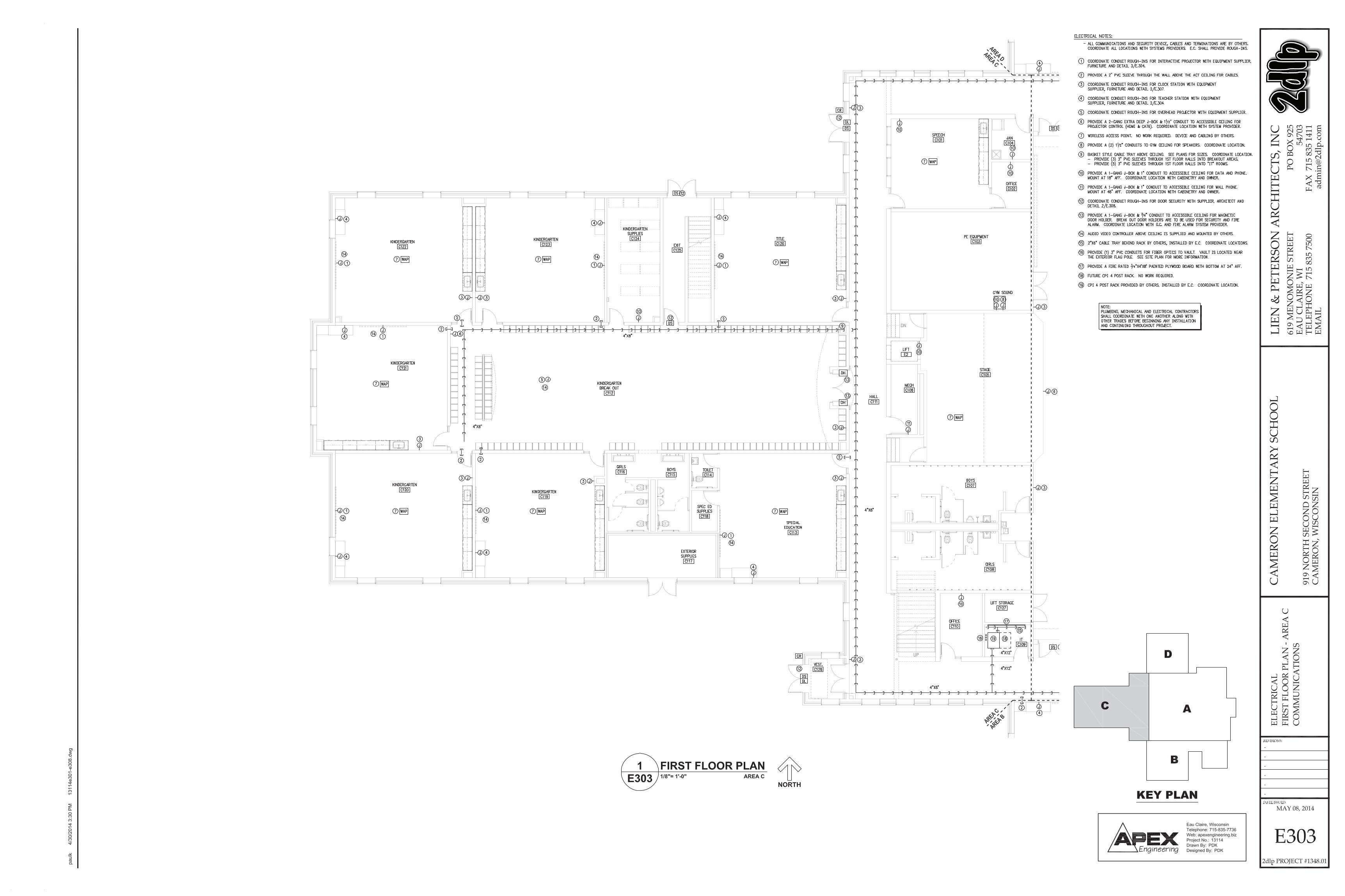
building is approximately 94,000 finished square feet. The two-story building is designed with the potential 37
for future growth and expansion. The school consists of public space including gymnasium, commons, 38
corridors, and cafeteria. Each grade is designated in a pod configuration, and has a breakout area. There are 39
a total of classrooms, with additional offices, rooms and spaces per the attached drawings. 40
41
There are two IT closets on the main floor with cable tray and conduit locations to each door requiring 42
access and security. The current design has designed the RFID locations, door switch locations, and 43
lockdown locations for the project. The proposing contractor shall include all required equipment and 44
wiring to each door location for their work. The attached documents indicate the doors and locations of all 45
required equipment. 46
47
The following will be furnished and installed by the owner (selected contractor will be required to 48
coordinate with owner’s representative and general contractor): 49
• Cameras 50
• Computers for software installation 51
• General building construction (currently in progress) 52
53

00 11 13 - 2
The awarded contractor will be contracted under the General Contractor: RJ Jurowski Construction, Inc. 1
Therefore, coordination and installation will be coordinated as such under the current construction schedule 2
by the general contractor. 3
4
PRE-BID MEETING 5
A mandatory pre-bid meeting will be held on Tuesday, February 17, 2015 at 10:00am. Meeting place will 6
be the Cameron Elementary School Project office, 919 N 2nd Street, Cameron, WI 54822. 7
8
TIMELINE 9
Installation of all access points, monitor switches and software shall be completed on or before August 1, 10
2015. 11
12
DELIVERABLES 13
If interested in submitting a design/build proposal, the contractor shall provide with their proposal package 14
the following: 15
• Project list of a minimum of (5) similar projects completed in the last (3) years. 16
• Proposal 17
• Certificate of Liability Insurance 18
• Proposed installation contractor and dates 19
20
BONDING 21
100% Performance and Payment Bonds are required upon approval and acceptance of the owner. 22
23
DOCUMENT AVAILABILITY 24
Drawings, Specifications and other Contract Documents have been prepared by LIEN & PETERSON 25
ARCHITECTS, INC., 619 Menomonie St., Eau Claire, WI. Documents will be available on or after 26
February 6, 2015. 27
28
Bidding documents may be examined at http://2dlp.com/planholders.html as well as various Builders 29
Exchanges including Eau Claire, La Crosse & Reed Construction Data. 30
31
ENCLOSURE 32
E301-E308 Communications (sheet for conduit locations and references) 33
Section 08 71 00 Door Hardware Specifications 34
35
END OF SECTION 36


Vostro 460P
TextBox
DS
Vostro 460P
TextBox
DS


08 71 00 - 1
SECTION 08 71 001
DOOR HARDWARE2
PART 1 - GENERAL3
SUMMARY4
Section Includes: Finish Hardware for door openings, except as otherwise specified herein.5
Door hardware for steel (hollow metal) doors.6
Door hardware for aluminum doors.7
Door hardware for wood doors.8
Door hardware for other doors indicated.9
Keyed cylinders as indicated.10
Related Sections:11
Division 8: Aluminum Doors and Frames.12
Division 8: Hollow Metal Doors and Frames.13
Division 8: Wood Doors.14
Division 26 Electrical.15
Division 28: Electronic Security.16
References: Comply with applicable requirements of the following standards. Where these standards conflict17
with other specific requirements, the most restrictive shall govern.18
Builders Hardware Manufacturing Association (BHMA).19
NFPA 101 - Life Safety Code.20
NFPA 80 - Fire Doors and Windows.21
ANSI-A156.xx - Various Performance Standards for Finish Hardware.22
UL10C - Positive Pressure Fire Test of Door Assemblies.23
ANSI-A117.1 - Accessible and Usable Buildings and Facilities.24
DHI /ANSI A115.IG - Installation Guide for Doors and Hardware.25
ICC - International Building Code.26
Intent of Hardware Groups:27
Should items of hardware not definitely specified be required for completion of the Work, furnish such28
items of type and quality comparable to adjacent hardware and appropriate for service required.29
Where items of hardware aren’t definitely or correctly specified, are required for completion of the Work,30
a written statement of such omission, error, or other discrepancy to be submitted to Architect, prior to31
date specified for receipt of bids for clarification by addendum; or, furnish such items in the type and32
quality established by this specification, and appropriate to the service intended.33
Allowances:34
Refer to Division 1 for allowance amount and procedures.35
Alternates:36
Refer to Division 1 for Alternates and procedures.37
SUBSTITUTIONS38
Comply with requirements of Division 1.39
SUBMITTALS40
Comply with requirements of Division 1.41
Special Submittal Requirements: Combine submittals of this Section with Sections listed below to ensure the42
"design intent" of the system/assembly is understood and can be reviewed together.43
Product Data: Manufacturer's specifications and technical data including the following:44
Detailed specification of construction and fabrication.45
Manufacturer's installation instructions.46
Wiring diagrams for each electric product specified. Coordinate voltage with electrical before submitting.47
Submit 6 copies of catalog cuts with hardware schedule.48
Provide 9001-Quality Management and 14001-Environmental Management for products listed in49
Materials Section 2.2.50
Shop Drawings - Hardware Schedule: Submit 6 complete reproducible copy of detailed hardware schedule in a51
vertical format.52
List groups and suffixes in proper sequence.53
Completely describe door and list architectural door number.54
Manufacturer, product name, and catalog number.55

08 71 00 - 2
Function, type, and style.56
Size and finish of each item.57
Mounting heights.58
Explanation of abbreviations and symbols used within schedule.59
Detailed wiring diagrams, specially developed for each opening, indicating all electric hardware, security60
equipment and access control equipment, and door and frame rough-ins required for specific opening.61
Templates: Submit templates and "reviewed Hardware Schedule" to door and frame supplier and others as62
applicable to enable proper and accurate sizing and locations of cutouts and reinforcing.63
Templates, wiring diagrams and "reviewed Hardware Schedule" of electrical terms to electrical for64
coordination and verification of voltages and locations.65
Samples: (If requested by the Architect)66
1 sample of Lever and Rose/Escutcheon design, (pair).67
3 samples of metal finishes.68
Contract Closeout Submittals: Comply with requirements of Division 1 including specific requirements69
indicated.70
Operating and maintenance manuals: Submit 3 sets containing the following.71
Complete information in care, maintenance, and adjustment, and data on repair and replacement72
parts, and information on preservation of finishes.73
Catalog pages for each product.74
Name, address, and phone number of local representative for each manufacturer.75
Parts list for each product.76
Copy of final hardware schedule, edited to reflect, "As installed".77
Copy of final keying schedule78
As installed “Wiring Diagrams” for each piece of hardware connected to power, both low voltage and79
110 volts.80
One set of special tools required for maintenance and adjustment of hardware, including changing of81
cylinders.82
QUALITY ASSURANCE83
Comply with requirements of Division 1.84
Statement of qualification for distributor and installers.85
Statement of compliance with regulatory requirements and single source responsibility.86
Distributor's Qualifications: Firm with 3 years experience in the distribution of commercial hardware.87
Distributor to employ full time Architectural Hardware Consultants (AHC) for the purpose of88
scheduling and coordinating hardware and establishing keying schedule.89
Hardware Schedule shall be prepared and signed by an AHC.90
Installer's Qualifications: Firm with 3 years experienced in installation of similar hardware to that91
required for this Project, including specific requirements indicated.92
Regulatory Label Requirements: Provide testing agency label or stamp on hardware for labeled openings.93
Provide UL listed hardware for labeled and 20 minute openings in conformance with requirements94
for class of opening scheduled.95
Underwriters Laboratories requirements have precedence over this specification where conflict96
exists.97
Single Source Responsibility: Except where specified in hardware schedule, furnish products of only one98
manufacturer for each type of hardware.99
Review Project for extent of finish hardware required to complete the Work. Where there is a conflict between100
these Specifications and the existing hardware, notify the Architect in writing and furnish hardware in101
compliance with the Specification unless otherwise directed in writing by the Architect.102
DELIVERY, STORAGE, AND HANDLING103
Packing and Shipping: Comply with requirements of Division 1.104
Deliver products in original unopened packaging with legible manufacturer's identification.105
Package hardware to prevent damage during transit and storage.106
Mark hardware to correspond with "reviewed hardware schedule".107
Deliver hardware to door and frame manufacturer upon request.108
Storage and Protection: Comply with manufacturer's recommendations.109

08 71 00 - 3
PROJECT CONDITIONS110
Coordinate hardware with other work. Furnish hardware items of proper design for use on doors and frames of111
the thickness, profile, swing, security and similar requirements indicated, as necessary for the proper installation112
and function, regardless of omissions or conflicts in the information on the Contract Documents.113
Review Shop Drawings for doors and entrances to confirm that adequate provisions will be made for the proper114
installation of hardware.115
WARRANTY116
Refer to Conditions of the Contract.117
Manufacturer’s Warranty:118
Closers: Ten years.119
Exit Devices: Five years.120
Locksets & Cylinders: Three years.121
All other Hardware: Two years.122
OWNER’S INSTRUCTION123
Instruct Owner’s personnel in operation and maintenance of hardware units.124
MAINTENANCE125
Extra Service Materials: Deliver to Owner extra materials from same production run as products installed.126
Package products with protective covering and identify with descriptive labels. Comply with Division 1 Closeout127
Submittals Section.128
Special Tools: Provide special wrenches and tools applicable to each different or special hardware129
component.130
Maintenance Tools: Provide maintenance tools and accessories supplied by hardware component131
manufacturer.132
Delivery, Storage and Protection: Comply with Owner’s requirements for delivery, storage and protection133
of extra service materials.134
Maintenance Service: Submit for Owner’s consideration maintenance service agreement for electronic products135
installed.136
PART 2 - PRODUCTS137
MANUFACTURERS138
The following manufacturers are approved subject to compliance with requirements of the Contract Documents.139
Approval of manufacturers other than those listed shall be in accordance with requirements of Division 1.140
141
Item: Manufacturer: Approved:142
Hinges Stanley Bommer, McKinney143
Continuous Hinges ABH Stanley, Select144
Locksets Best No Substitution - Owner's Standard145
Cylinders Best No Substitution - Owner's Standard146
Exit Devices Precision Von Duprin147
Electric Strikes Stanley Hes148
Closers Stanley D-4550 Norton 7500149
Automatic Operators Stanley D-4990 LCN 4640, Norton150
Push/Pull Plates Trimco Hager, Rockwood151
Push/Pull Bars Trimco Hager, Rockwood152
Protection Plates Trimco Hager, Rockwood153
Overhead Stops ABH Rixson, Glynn Johnson154
Door Stops Trimco Hager, Rockwood155
Flush Bolts ABH Trimco, Rockwood156
Coordinator & Brackets ABH Trimco, Rockwood157
Threshold & Gasketing National Guard Reese, Pemko158
MATERIALS159
Hinges:160
Template screw hole locations161
Minimum of 2 permanently lubricated non-detachable bearings162
Equip with easily seated, non-rising pins163
Sufficient size to allow 180-degree swing of door164

08 71 00 - 4
Furnish hinges with five knuckles and flush concealed bearings165
Provide hinge type as listed in schedule.166
Furnish 3 hinges per leaf to 7 foot 6 inch height. Add one for each additional 30 inches in height or167
fraction thereof.168
Tested and approved by BHMA for all applicable ANSI Standards for type, size, function and finish169
UL10C listed for Fire rated doors.170
Geared Continuous Hinges:171
Tested and approved by BHMA for ANSI A156.26-1996 Grade 1.172
Anti-spinning through fastener.173
Non-handed.174
Provide Fire Pins for 3-hour fire ratings.175
Sufficient size to permit door to swing 180 degrees.176
Cylindrical Type Locks and Latchsets:177
Tested and approved by BHMA for ANSI A156.2, Series 4000, Operational Grade 1, Extra-Heavy Duty,178
and be UL10C listed.179
Provide 9001-Quality Management and 14001-Environmental Management.180
Fit modified ANSI A115.2 door preparation.181
Locksets and cores to be of the same manufacturer to maintain complete lockset warranty.182
Locksets to have anti-rotational studs that are thru-bolted.183
Keyed lever shall not have exposed “keeper” hole.184
Each lever to have independent spring mechanism controlling it.185
2-3/4 inch (70 mm) backset.186
9/16 inch (14 mm) throw latchbolt.187
Provide sufficient curved strike lip to protect door trim.188
Outside lever sleeve to be seamless, of one-piece construction made of a hardened steel alloy.189
Keyed lever to be removable only after core is removed, by authorized control key.190
Provide locksets with 7-pin removable and interchangeable core cylinders.191
Hub, side plate, shrouded rose, locking pin to be a one-piece casting with a shrouded locking lug.192
Locksets outside locked lever must withstand minimum 1400 inch pounds of torque. In excess of that, a193
replaceable part will shear. Key from outside and inside lever will still operate lockset.194
Core face must be the same finish as the lockset.195
Functions and design as indicated in the hardware groups.196
Trim Design: "15" Lever Design; "D" Style Rose.197
Exit Devices:198
Exit devices to meet or exceed BHMA for ANSI 156.3, Grade 1.199
Exit devices to be tested and certified by UL or by a recognized independent laboratory for mechanical200
operational testing to 9 million cycles minimum with inspection confirming Grade 1 Loaded Forces have201
been maintained.202
Exit devices chassis to be investment cast steel, zinc dichromate.203
Exit devices to have stainless steel deadlocking ¾” through latch bolt.204
Exit devices to be equipped with sound dampening on touchbar.205
Non-fire rated exit devices to have cylinder dogging if specified.206
Non-fire rated exit devices to have ¼” minimum turn hex key dogging.207
Touchpad to be “T” style constructed of architectural metal with matching metal end caps.208
Touchbar assembly on wide style exit devices to have a ¼” clearance to allow for vision frames.209
All exposed exit device components to be of architectural metals and “true” architectural finishes.210
Provide strikes as required by application.211
Fire exit hardware to conform to UL10C and UBC 7-2. UL tested for Accident Hazard.212
Exit device to be heavy investment cast stainless steel with black powder coated finish.213
Exit devices to have field reversible handing.214
Provide heavy duty vandal resistant lever trim with heavy duty investment cast stainless steel components215
and extra strength shock absorbing overload springs. Lever shall not require resetting. Lever design to216
match locksets and latchsets.217
Provide 9001-Quality Management and 14001-Environmental Management.218
Vertical Latch Assemblies to have gravity operation, no springs.219

08 71 00 - 5
Trim Design: 4900 Escutcheon with "A" Lever.220
Cylinders:221
Provide the necessary cylinder housings, collars, rings & springs as recommended by the manufacturer222
for proper installation.223
Provide the proper cylinder cams or tail piece as required to operate all locksets and other keyed hardware224
items listed in the hardware sets.225
Coordinate and provide as required for related sections.226
227
Door Closers:228
Tested and approved by BHMA for ANSI 156.4, Grade 1.229
UL10C certified.230
Provide 9001-Quality Management and 14001-Environmental Management.231
Closer shall have extra-duty arms and knuckles.232
Conform to ANSI 117.1.233
Maximum 2 7/16 inch case projection with non-ferrous cover.234
Separate adjusting valves for closing and latching speed, and backcheck.235
Provide adapter plates, shim spacers and blade stop spacers as required by frame and door conditions.236
Full rack and pinion type closer with 1½“ minimum bore.237
Mount closers on non-public side of door, unless otherwise noted in specification.238
Closers shall be non-handed, non-sized and multi-sized.239
Low Energy Operators:240
Conform to ANSI/BHMA A156.19 as a low energy power opening device.241
Be listed under UL228, UL325, UL10B, UL10C, UBC 7.2 and FCC listed.242
Shall be non-handed.243
Be rated for door panels weighing up to 350 lbs (160 kg).244
The manual door closer within the Low Energy Operator shall be adjusted to meet Americans with245
Disabilities Act (ADA) 5 lbs opening force [Push-Side applications only]246
Operator shall be isolated from mounting plate with rubber mounts to mitigate the transmission of forces247
between the door and the operator.248
Shall have a position encoder to communicate with microprocessor.249
Incorporate a resettable powered operation counter that tracts both powered and non-powered cycling of250
the Operator.251
Incorporate the following adjustable settings:252
Hold Open Timer, to 28 seconds.253
Open Speed.254
Backcheck Speed.255
Vestibule Sequence Timer.256
Include DIP switch controls for:257
On board diagnostics.258
Power close.259
Push and Go operation.260
Time delay logic for electrified hardware components.261
Include terminals for auxiliary controls including:262
Activation devices; provide two discrete inputs.263
Vestibule sequencing.264
Control switches including:265
Day/Night open (illuminated).266
Power On-Off.267
Includes adhesive Low Energy Operator mounting templates.268
R-14 Aluminum Alloy Materials.269
For non-powered operation, the unit shall function as a standard door closer with adjustable spring force270
size 1 thru 6.271
Door Stops: Provide a dome floor or wall stop for every opening as listed in the hardware sets.272
Wall stop and floor stop shall be wrought bronze, brass or stainless steel.273
Provide fastener suitable for wall construction.274

08 71 00 - 6
Coordinate reinforcement of walls where wall stop is specified.275
Provide dome stops where wall stops are not practical. Provide spacers or carpet riser for floor conditions276
encountered.277
Over Head Stops: Provide a Surface mounted or concealed overhead when a floor or wall stop cannot be used or278
when listed in the hardware set.279
Concealed overhead stops shall be heavy duty bronze or stainless steel.280
Surface overhead stops shall be heavy duty bronze or stainless steel.281
Push Plates: Provide with four beveled edges ANSI J301, .050 thickness, size as indicated in hardware set.282
Furnish oval-head countersunk screws to match finish.283
Pulls with Plates: Provide with four beveled edges ANSI J301, .050 thickness Plate s with ANSI J401 Pull as284
listed in hardware set. Provide proper fasteners for door construction.285
Push Pull Bars: Provide ANSI J504, .1” Dia. Pull and push bar model and series as listed in hardware set.286
Provide proper fasteners for door construction.287
Kickplates: Provide with four beveled edges ANSI J102, 10 inches high by width less 2 inches on single doors288
and 1 inch on pairs of doors. Furnish oval-head countersunk screws to match finish.289
Armor Plates: Provide ANSI J101 with four beveled edges, 34 inches high by width less 1 inch on single or pairs290
of doors. Furnish oval-head countersunk screws to match finish.291
Provide cutouts for hardware as listed in the hardware sets.292
Provide Warnock Hersey labeled plates for 3 hour metal fire doors where allowed by local authority.293
Door Bolts: Flush bolts for wood or metal doors.294
Provide a set of Automatic bolts, Certified ANSI/BHMA 156.3 Type 25 for hollow metal label doors.295
Provide a set of Automatic bolts, Certified ANSI/BHMA 156.3 Type 27 at wood label doors.296
Manual flush bolts, Certified ANSI/BHMA 156.16 at openings where allowed local authority.297
Provide Dust Proof Strike, Certified ANSI/BHMA 156.16 at doors with flush bolts without thresholds.298
Coordinator and Brackets: Provide a surface mounted coordinator when automatic bolts are used in the hardware299
set.300
Coordinator, Certified ANSI/BHMA A1156.3 Type 21A for full width of the opening.301
Provide mounting brackets for soffit applied hardware.302
Provide hardware preparation (cutouts) for latches as necessary.303
Power Supply: Provide power supply for (ELR) Electric Latch Retraction exit devices304
Motherboard will accept up to four plug-in Control Modules. Provide the appropriate necessary control305
module to operate the number of ELR exit devices used at each opening. The Control Module shall306
include a Time delay Feature, variable (0-4 minutes) latch retraction period in response to a momentary307
input.308
UL Listed for class II output.309
Include circuit breakers for protection of motherboard.310
115 or 230 Volt user selectable switch, with AC input= 115 Volt at 1 Amp.311
Control module shall include Fire alarm terminal and Auxiliary contacts for remote signaling.312
Optional card for Battery Backup (BT) power tap module to operate a Card reader or when ELR devices313
require battery backup (Lead Acid Batteries are not included and is to be furnished by others).314
Precision ELR150 Series with the required modules.315
Power Transfer: Power transfer device shall be a steel housing and flexible tube. Secure and inconspicuous316
channel is to bring power from the frame to the door.317
Precision EPT-5.318
Tube shall accept up to 5/16” wire bundle and accommodate a door swing of 120 Deg.319
Wires as required by others.320
Power Supply: UL Listed, Field Selectable 12VDC or 24VDC output. The power supply will specifically321
designed to support electric locks and access controls. The power supply uses 115 VAC at 800mA input. The322
power shall be able to be expanded to four station controls. The filtered and regulated output power is field323
selectable for 12 or 24 VDC.324
Fire Alarm/Life Safety emergency release included in power supply.325
Available options for multiple door options four or more control stations, Adjustable Time delay relay,326
Battery charging, Battery Back up.327
Door Position Switch: Provide door position switch for door status monitoring as indicated in hardware sets.328

08 71 00 - 7
At all fired rated doors the door and frames, position switch preparation will be provided by the door and329
frame manufacturer or by an authorized label service agent.330
Electric Door Strike: ANSI/BHMA 156.31, Grade 1 and listed ANSI/ UL1034, Warnock Hersey.331
The ES5 electric strike will accept up to a 3/4" latch bolt and 1” deadbolt. Field reversible, failsafe/fail332
secure.333
Listed UL10C Fire Door assemblies for Single Door application.334
UL tested 1500 lb static strength.335
ES5 Electrical Specifications Dual Voltage coil 600mA @12V DC, 300mA @24V AC.336
Contacts: SPDT, Dry, 5 Amp @30V.337
Magnetic Door Holders: Provide magnetic door holders with Tri-Voltage that can be wired 12VDC, 24V AC/DC338
or 120V AC.339
Wall magnetic door holders shall be Surface mounted.340
Armature shall be thru-bolted and can be provided with any projection required.341
Models will be available in US28, sprayed finishes and US32D.342
Gasketing and Seals: All gasketing and seals shall be finished to match adjacent frame color. Gasketing and seals343
shall be furnished as listed in schedule. Material shall be UL listed for labeled openings.344
Weatherstripping: Provide at head and jambs only those units where resilient or flexible seal strip is easily345
replaceable. Where bar-type weatherstrip is used with parallel arm mounted closers install weatherstrip first.346
Weatherstrip shall be resilient seal of Pile.347
Door Bottoms/Sweeps: Surface mounted or concealed door bottom where listed in the hardware sets.348
Door seal shall be resilient seal of Neoprene.349
UL10C Positive Pressure rated seal set when required.350
Thresholds: Thresholds shall be aluminum beveled type with maximum height of ½” for conformance with ADA351
requirements. Furnish as specified and per details. Provide fasteners and screws suitable for floor conditions.352
Provide one wall mounted Telkee, Lund or MMF series key cabinet complete with hooks, index and tags to353
accommodate 50% expansion. Coordinate mounting location with architect.354
Key Control Software: Provide one, Keystone® 600N key management control software. Shall include general355
features.356
Password restricted logins.357
List all keys and items currently due back (or due back by any day designated).358
Lists all cores and their location, building and doors, and cross-references people to cores, doors, and359
building they access.360
Comprehensive list of reports available as an on-screen menu.361
Built-in easy to use backup program.362
Program always displays date of last backup.363
Dynamic searching capabilities for all records.364
On-screen indicator shows when historical info. Is present for a record.365
On-screen indicator appears when notes are present on a record.366
Able to operate in an NTFS network environment with TCPIP protocol.367
Multiple users can access program at the same time.368
Software shall include a “Best” Automated Pin Segment Calculator and a Manual Pin Segment Calculator369
for authorized “Best” building lock shop facilities.370
Software program is to be compatible with Windows NT, 2000 or XP with TCPIP protocol.371
Silencers: Furnish silencers on all interior frames, 3 for single doors, 2 for pairs. Omit where any type of seals or372
gaskets occur.373
FINISH374
Designations used in Schedule of Finish Hardware - 3.05, and elsewhere to indicate hardware finishes are those375
listed in ANSI/BHMA A156.18 including coordination with traditional U.S. finishes shown by certain376
manufacturers for their products377
Powder coat door closers to match other hardware, unless otherwise noted.378
Aluminum items shall be finished to match predominant adjacent material. Seals to coordinate with frame color.379
KEYS AND KEYING380
Provide keyed brass construction cores and keys during the construction period. Construction control and381
operating keys and core shall not be part of the Owner's permanent keying system or furnished in the same382

08 71 00 - 8
keyway (or key section) as the Owner's permanent keying system. Permanent cores and keys (prepared383
according to the accepted keying schedule) will be furnished to the Owner.384
Cylinders, removable and interchangeable core system: Best CORMAX™ Patented 7-pin.385
Permanent keys and cores: Stamped with the applicable key mark for identification. These visual key control386
marks or codes will not include the actual key cuts. Permanent keys will also be stamped "Do Not Duplicate."387
Transmit Grand Masterkeys, Masterkeys and other Security keys to Owner by Registered Mail, return receipt388
requested.389
Furnish keys in the following quantities:390
1 each Grand Masterkeys391
4 each Masterkeys392
2 each Change keys each keyed core393
15 each Construction masterkeys394
1 each Control keys395
The Owner, or the Owner's agent, will install permanent cores and return the construction cores to the Hardware396
Supplier. Construction cores and keys remain the property of the Hardware Supplier.397
Keying Schedule: Arrange for a keying meeting, and programming meeting with Architect Owner and hardware398
supplier, and other involved parties to ensure locksets and locking hardware, are functionally correct and keying399
and programming complies with project requirements. Furnish 3 typed copies of keying and programming400
schedule to Architect.401
PART 3 - EXECUTION402
EXAMINATION403
Verification of conditions: Examine doors, frames, related items and conditions under which Work is to be404
performed and identify conditions detrimental to proper and or timely completion.405
Do not proceed until unsatisfactory conditions have been corrected.406
HARDWARE LOCATIONS407
Mount hardware units at heights indicated in the following publications except as specifically indicated or408
required to comply with the governing regulations.409
Recommended Locations for Builder’s Hardware for Standard Steel Doors and Frames, by the Door and410
Hardware Institute (DHI).411
Recommended locations for Architectural Hardware for flush wood doors (DHI).412
WDMA Industry Standard I.S.-1A-04, Industry Standard for Architectural wood flush doors.413
INSTALLATION414
Install each hardware item per manufacturer's instructions and recommendations. Do not install surface mounted415
items until finishes have been completed on the substrate. Set units level, plumb and true to line and location.416
Adjust and reinforce the attachment substrate as necessary for proper installation and operation.417
Conform to local governing agency security ordinance.418
Install Conforming to ICC/ANSI A117.1 Accessible and Usable Building and Facilities.419
Adjust door closer sweep periods so that from the open position of 70 degrees, the door will take at least420
3 seconds to move to a point 3 inches from the latch, measured to the landing side of the door.421
Installed hardware using the manufacturers fasteners provided. Drill and tap all screw holes located in metallic422
materials. Do not use “Riv-Nuts” or similar products.423
FIELD QUALITY CONTROL AND FINAL ADJUSTMENT424
Contractor/Installers, Field Services: After installation is complete, contractor shall inspect the completed door425
openings on site to verify installation of hardware is complete and properly adjusted, in accordance with both the426
Contract Documents and final shop drawings.427
Check and adjust closers to ensure proper operation.428
Check latchset, lockset, and exit devices are properly installed and adjusted to ensure proper operation.429
Verify levers are free from binding.430
Ensure latchbolts and dead bolts are engaged into strike and hardware is functioning.431
Report findings, in writing, to architect indicating that all hardware is installed and functioning properly.432
Include recommendations outlining corrective actions for improperly functioning hardware if required.433
End of Section434

08 71 00 - 9
SCHEDULE OF FINISH HARDWARE435
Manufacturer List
Code Name
AB ABH Manufacturing Inc.
AB Architectural Builders Hardware
BE Best Access Systems
BY By Others
DE Detex
IV Ives
NA National Guard
PR Precision
SD Stanley Door Closers
SDCO Security Door Controls
SENT Sentrol
ST Stanley
TR Trimco
Finish List
Code Description
AL Aluminum
26D Satin Chrome
313 Dark Bronze Duranodic
600 Primed for Painting
613 Dark Oxidized Satin Bronze - Equivalent
626 Satin Chromium Plated
628 Satin Aluminum, Clear Anodized
630 Satin Stainless Steel
689 Aluminum Painted
695 Dark Bronze Painted
GREY Grey
US26D Chromium Plated, Dull
US32D Stainless Steel, Dull
BRONZE Bronze

08 71 00 - 10
Option List
Code Description
W Weatherized
CD CYLINDER DOGGING
DS DOOR POSITION SWITCH
FL Fire Exit Hardware
LD Less Dogging
LM LOST MOTION
LS Less Strike
M1 BRONZE CHAIN
PT Power Transfer
S3 ANSI Strike Package
SN Sex Nuts (Pkg. of 4)
WC PADLOCK WEATHER COVERS
3/4 3/4" THROW LATCH
3RO Prefix option for 2000 Apex Series
ELR ELECTRIC LATCH RETRACTION
LBR LESS BOTTOM ROD
MCS Mullion Cap Spacer (600 Finish)
MCS Mullion Cap Spacer (other Finishes)
SEC SECURITY SCREWS - 2200
STK Standard Strike Package
STS STAINLESS PINS - 4 1/2", 5"
S300 STD. STRIKE - RIM AND TOP OF SVR DEVICES
S458 OPT. ROLLER. STRIKE - RIM DEVICES
SSK3 Torx Screw Kit (Value Series)
P45-180 Drop Plate
SNB (6) SEX BOLTS (6)
SNB (8) SEX BOLTS (8)
END CAPS Set of End Caps
P45HD-110 Spacer Block HD Arm on Rabbet
P45HD-112 Angle Brkt. - Shoe Support HD Arms
#99 Strike Standard #99 Surface Strike
Strike Prep Strike Prep
C-SUNK HOLES COUNTER SINKING OF KICK and MOP PLATES
Top/Bottom Flush Bolt Prep Top/Bottom Flush Bolt Preps

08 71 00 - 11
Hardware SetsSET #1 - Int - Sgl - Push/Pull
Doors: C107.1, C108.1
3 Hinges CB179 4 1/2 X 4 1/2 US26D ST
1 Push/Pull Plate Combo 1895-4B 630 TR
1 Door Closer CLD-4550 STD W/PA BRKT SN 689 SD
1 Kick Plate KO050 10" x 2" LDW CSK 630 TR
1 Wall Bumper 1270WV 630 TR
3 Door Silencers 1229A GREY TR
SET #2 - Int - Sgl - Passage
Doors: A104.1, A130.1, B105.2
3 Hinges CB179 4 1/2 X 4 1/2 US26D ST
1 Passage Set 9K3-0N15D S3 626 BE
1 Door Closer CLD-4550 STD W/PA BRKT SN 689 SD
1 Wall Bumper 1270WV 630 TR
3 Door Silencers 1229A GREY TR
NOTE: Add Kickplate KO050 10" x 2" LDW CSK to Door 105.2.
SET #3 - Int - Sgl - Passage
Doors: D115.1, D115.2
3 Hinges CB179 4 1/2 X 4 1/2 US26D ST
1 Passage Set 9K3-0N15D S3 626 BE
1 Door Closer CLD-4550 H 689 SD
1 Kick Plate KO050 10" x 2" LDW CSK 630 TR
3 Door Silencers 1229A GREY TR
SET #4 - Int - Sgl - Privacy
Doors: A102.1, A113.1, B215.1, D103.1
3 Hinges CB179 4 1/2 X 4 1/2 US26D ST
1 Privacy Set 9K3-0L15D S3 626 BE
1 Wall Bumper 1270WV 630 TR
3 Door Silencers 1229A GREY TR
SET #5 - Int - Sgl - Privacy
Doors: A106.1, A108.1, A205.1, A206.1, B104.1, C114.1, D116.1
3 Hinges CB179 4 1/2 X 4 1/2 US26D ST
1 Privacy Set 9K3-0L15D S3 626 BE
1 Door Closer CLD-4550 STD W/PA BRKT SN 689 SD
1 Wall Bumper 1270WV 630 TR
3 Door Silencers 1229A GREY TR
08 71 00 - 12
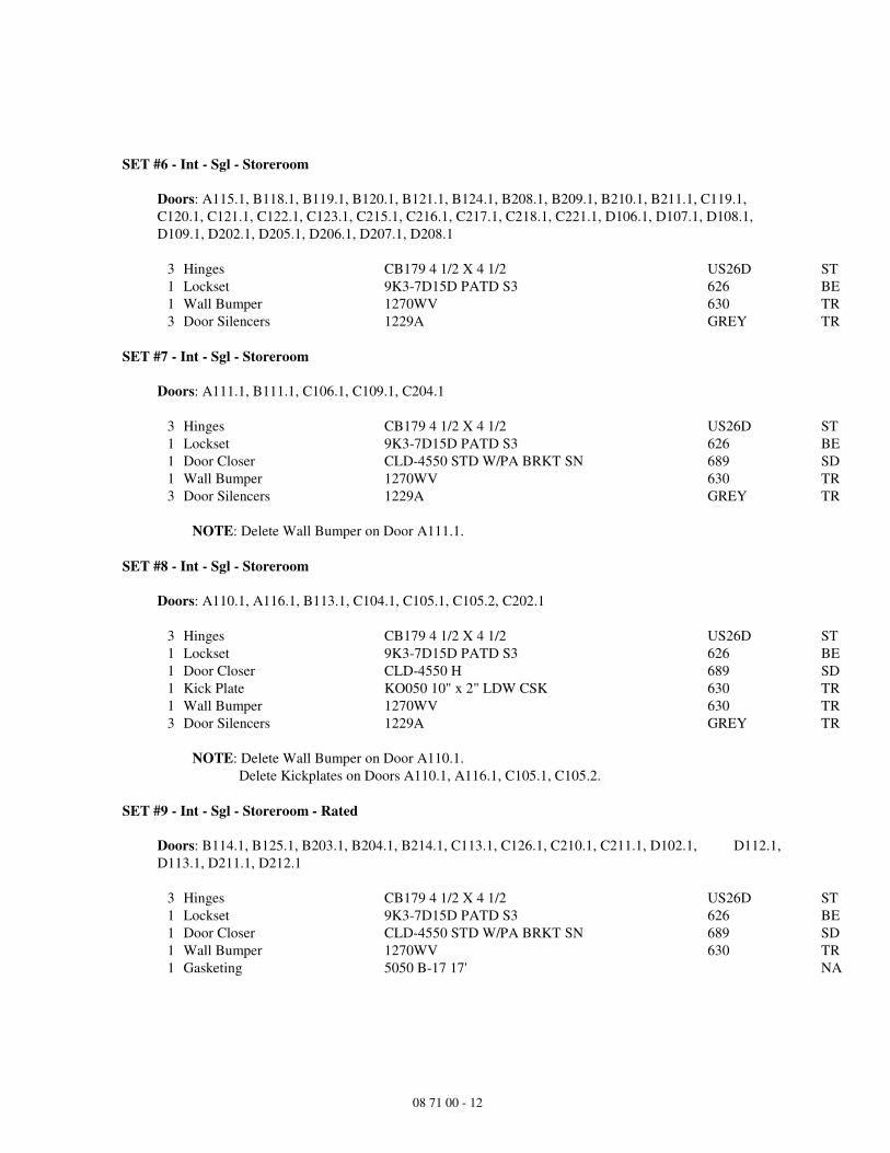
SET #6 - Int - Sgl - Storeroom
Doors: A115.1, B118.1, B119.1, B120.1, B121.1, B124.1, B208.1, B209.1, B210.1, B211.1, C119.1,
C120.1, C121.1, C122.1, C123.1, C215.1, C216.1, C217.1, C218.1, C221.1, D106.1, D107.1, D108.1,
D109.1, D202.1, D205.1, D206.1, D207.1, D208.1
3 Hinges CB179 4 1/2 X 4 1/2 US26D ST
1 Lockset 9K3-7D15D PATD S3 626 BE
1 Wall Bumper 1270WV 630 TR
3 Door Silencers 1229A GREY TR
SET #7 - Int - Sgl - Storeroom
Doors: A111.1, B111.1, C106.1, C109.1, C204.1
3 Hinges CB179 4 1/2 X 4 1/2 US26D ST
1 Lockset 9K3-7D15D PATD S3 626 BE
1 Door Closer CLD-4550 STD W/PA BRKT SN 689 SD
1 Wall Bumper 1270WV 630 TR
3 Door Silencers 1229A GREY TR
NOTE: Delete Wall Bumper on Door A111.1.
SET #8 - Int - Sgl - Storeroom
Doors: A110.1, A116.1, B113.1, C104.1, C105.1, C105.2, C202.1
3 Hinges CB179 4 1/2 X 4 1/2 US26D ST
1 Lockset 9K3-7D15D PATD S3 626 BE
1 Door Closer CLD-4550 H 689 SD
1 Kick Plate KO050 10" x 2" LDW CSK 630 TR
1 Wall Bumper 1270WV 630 TR
3 Door Silencers 1229A GREY TR
NOTE: Delete Wall Bumper on Door A110.1.
Delete Kickplates on Doors A110.1, A116.1, C105.1, C105.2.
SET #9 - Int - Sgl - Storeroom - Rated
Doors: B114.1, B125.1, B203.1, B204.1, B214.1, C113.1, C126.1, C210.1, C211.1, D102.1, D112.1,
D113.1, D211.1, D212.1
3 Hinges CB179 4 1/2 X 4 1/2 US26D ST
1 Lockset 9K3-7D15D PATD S3 626 BE
1 Door Closer CLD-4550 STD W/PA BRKT SN 689 SD
1 Wall Bumper 1270WV 630 TR
1 Gasketing 5050 B-17 17' NA

08 71 00 - 13
SET #10 - Int - Sgl - Storeroom - Rated
Doors: B112.1, B205.1, C203.1, C209.1, D114.1, D213.1
3 Hinges CB168 4 1/2 X 4 1/2 US26D ST
1 Lockset 9K3-7D15D PATD S3 626 BE
1 Door Closer CLD-4550 STD W/PA BRKT SN 689 SD
1 Wall Bumper 1270WV 630 TR
1 Gasketing 5050 B-17 17' NA
SET #11 - Int - Sgl - Storeroom - Access Control
Doors: A105.1, A119.1
3 Hinges CB179 4 1/2 X 4 1/2 US26D ST
1 Lockset 9K3-7D15D PATD S3 626 BE
1 Electric Strike - Fail Secure ES5 A S 630 BE
1 Power Supply 631RFA X UR2A SDCO
1 Door Closer CLD-4550 STD W/PA BRKT SN 689 SD
1 Wall Bumper 1270WV 630 TR
1 Door Position Switch 1078 CW SENT
1 Aiphone Intercom By Owner's Security Vendor - Door 119.1 BY
1 RFID Reader By Owner's Security Vendor - Door 105.1 BY
3 Door Silencers 1229A GREY TR
Function:
1. Doors normally closed and locked.
2. Door 105.1: Presenting valid credential to RFID reader releases electric strike allowing entry.
Mechanical key in outside cylinder retracts latchbolt for entry. Door re-locks after closure.
3. Door 119.1: Use of intercom system to request entry. Button in Reception area releases electric strike
for entry.
4. When power is lost, doors fail in locked position (Fail Secure).
5. Free Egress at all times by lever.
SET #12 - Int - Sgl - Keyed Restroom
Doors: C206.1, C207.1
3 Hinges CB179 4 1/2 X 4 1/2 US26D ST
1 Lockset 9K3-7H15D PATD S3 626 BE
1 Door Closer CLD-4550 STD W/PA BRKT SN 689 SD
1 Wall Bumper 1270WV 630 TR
3 Door Silencers 1229A GREY TR
Function:
1. Doors normally closed and locked. Mechanical key in outside cylinder retracts latchbolt for entry.
Door re-locks after closure.
2. Pushing inside button projects "Occupied" indicator in the outside lever and blocks all operating keys.
3. Free Egress at all times by lever.

08 71 00 - 14
SET #13 - Int - Sgl - Office
Doors: A117.1, A132.1, A209.1, A210.1, A218.1, B107.1, B122.1, B212.1, B216.1, C102.1, C118.1,
C124.1, C219.1, D105.1, D204.1
3 Hinges CB179 4 1/2 X 4 1/2 US26D ST
1 Lockset 9K3-7B15D PATD S3 626 BE
1 Wall Bumper 1270WV 630 TR
3 Door Silencers 1229A GREY TR
SET #14 - Int - Sgl - Office
Doors: A105.2, A114.1, A127.1, A129.1, A131.1, A201.1, A207.1, A208.1, B101.1, B101.2, B126.1,
C101.1, C110.1, C201.1
3 Hinges CB179 4 1/2 X 4 1/2 US26D ST
1 Lockset 9K3-7B15D PATD S3 626 BE
1 Door Closer CLD-4550 STD W/PA BRKT SN 689 SD
1 Wall Bumper 1270WV 630 TR
3 Door Silencers 1229A GREY TR
SET #15 - Int - Sgl - Office
Doors: A119.2
3 Hinges CB179 4 1/2 X 4 1/2 US26D ST
1 Lockset 9K3-7B15D PATD S3 626 BE
1 Door Closer CLD-4550 H 689 SD
1 Wall Bumper 1270WV 630 TR
3 Door Silencers 1229A GREY TR
SET #16 - Int - Sgl - Office
Doors: HS16
3 Hinges CB179 4 1/2 X 4 1/2 US26D ST
1 Lockset 9K3-7B15D PATD S3 626 BE
1 Door Closer CLD-4550 H 689 SD
1 Wall Bumper 1270WV 630 TR
1 Gasketing 5050 B-17 17' NA
1 Auto Door Bottom 220 NDKB 36" END CAPS NA
SET #17 - Int - Sgl - Gate
Doors: A118.1
2 Hinges CB168 4 1/2 X 4 1/2 US26D ST

08 71 00 - 15
SET #18 - Int - Sgl - Exit - Rated
Doors: B123.1, B213.1, C125.1, C220.1, D104.1, D203.1
3 Hinges CB179 4 1/2 X 4 1/2 US26D ST
1 Exit Device 3RO FL 2114 X 4914A DS S300 SNB (6) 630 PR
1 Door Closer CLD-4550 STD W/PA BRKT SN 689 SD
1 Kick Plate KO050 10" x 2" LDW CSK 630 TR
1 Wall Bumper 1270WV 630 TR
1 Gasketing 5050 B-17 17' NA
SET #19 - Int - Pair - Passage
Doors: A103.1
6 Hinges CB179 4 1/2 X 4 1/2 US26D ST
1 Manual Flush Bolt Set - Wood 1857P 26D AB
1 Passage Set 9K3-0N15D STK 626 BE
1 Set Dummy Trim 9K-02DT15D LS 626 BE
2 Overhead Stop 4020 SERIES 630 AB
1 Dust Proof Strike 1870 US26D AB
2 Door Silencers 1229A GREY TR
SET #20 - Int - Pair - Storeroom
Doors: A125.1, B108.1, C103.1, C127.1
6 Hinges CB179 4 1/2 X 4 1/2 US26D ST
1 Manual Flush Bolt Set - Wood 1857P 26D AB
1 Passage Set 9K3-0N15D STK 626 BE
1 Set Dummy Trim 9K-02DT15D LS 626 BE
2 Door Closer CLD-4550 HS P45HD-110 P45HD-112 SN 689 SD
2 Armor Plate KA050-2 34" x 2" LDW CSK UL (VERIFY) 630 TR
1 Dust Proof Strike 1870 US26D AB
2 Door Silencers 1229A GREY TR
NOTE: Add (2) Wall Bumpers Trimco 1270WV to Door B108.1.
SET #21 - Int - Pair - Storeroom
Doors: C222.1
6 Hinges CB179 4 1/2 X 4 1/2 US26D ST
1 Manual Flush Bolt Set - Wood 1857P 26D AB
1 Passage Set 9K3-0N15D STK 626 BE
1 Set Dummy Trim 9K-02DT15D LS 626 BE
2 Overhead Stop 4020 SERIES 630 AB
1 Dust Proof Strike 1870 US26D AB
2 Door Silencers 1229A GREY TR

08 71 00 - 16
SET #22 - Int - Pair - Storeroom - Rated
Doors: A124.1, A137.1
6 Hinges CB179 4 1/2 X 4 1/2 US26D ST
1 Auto Flush Bolt Set - Wood 1862P US32D AB
1 Lockset 9K3-7D15D PATD STK 626 BE
1 Set Dummy Trim 9K-02DT15D LS 626 BE
1 Coordinator 3700 SERIES 600 AB
2 Door Closer CLD-4550 S P45HD-110 P45HD-112 SN 689 SD
2 Armor Plate KA050-2 34" x 2" LDW CSK UL (VERIFY) 630 TR
1 Dust Proof Strike 1870 US26D AB
1 Astragal Set 561 SS 7'0" Strike Prep Top/Bottom Flush Bolt Prep NA
1 Smoke Seal 5075 B 84" NA
1 Gasketing 5050 B-20 20' NA
NOTE: Delete Armor Plates on Door A137.1.
SET #23 - Int - Pair - Office
Doors: A215.1
6 Hinges CB179 4 1/2 X 4 1/2 US26D ST
1 Manual Flush Bolt Set - Wood 1857P 26D AB
1 Lockset 9K3-7B15D PATD STK 626 BE
1 Set Dummy Trim 9K-02DT15D LS 626 BE
1 Wall Bumper 1270WV 630 TR
1 Floor Stop W1211 630 TR
1 Dust Proof Strike 1870 US26D AB
2 Door Silencers 1229A GREY TR
SET #24 - Int - Pair - Office
Doors: A203.1
6 Hinges CB179 4 1/2 X 4 1/2 US26D ST
1 Auto Flush Bolt Set - Wood 1862P US32D AB
1 Lockset 9K3-7B15D PATD STK 626 BE
1 Set Dummy Trim 9K-02DT15D LS 626 BE
1 Coordinator 3700 SERIES 600 AB
2 Door Closer CLD-4550 H 689 SD
2 Wall Bumper 1270WV 630 TR
1 Dust Proof Strike 1870 US26D AB
2 Door Silencers 1229A GREY TR

08 71 00 - 17
SET #25 - Int - Pair - Office
Doors: A211.1
6 Hinges CB179 4 1/2 X 4 1/2 US26D ST
1 Manual Flush Bolt Set - Wood 1857P 26D AB
1 Lockset 9K3-7B15D PATD STK 626 BE
1 Set Dummy Trim 9K-02DT15D LS 626 BE
2 Door Closer CLD-4550 H 689 SD
2 Floor Stop W1211 630 TR
1 Dust Proof Strike 1870 US26D AB
2 Door Silencers 1229A GREY TR
SET #26 - Int - Pair - Exit - Passage
Doors: B110.2
6 Hinges CB179 4 1/2 X 4 1/2 US26D ST
2 Exit Device 3RO 2214 X 4914A LBR S300 SEC SNB (8) 630 PR
2 Door Closer CLD-4550 STD W/PA BRKT SN 689 SD
2 Wall Bumper 1270WV 630 TR
2 Door Silencers 1229A GREY TR
SET #27 - Int - Pair - Exit
Doors: A128.2, A128.3, A128.4, C205.1, C205.2, C205.3
6 Hinges CB168 4 1/2 X 4 1/2 US26D ST
1 Exit Device 3RO 2203 X 4903A CD DS LBR S300 SEC SNB (8) 630 PR
1 Exit Device 3RO 2202 X 4902A CD DS LBR S300 SEC SNB (8) 630 PR
2 Mortise Cylinder 1E-74 PATD 626 BE
1 Rim Cylinder 12E-72 PATD 626 BE
2 Door Closer CLD-4550 H 689 SD
2 Kick Plate KO050 10" x 2" LDW CSK 630 TR
2 Wall Bumper 1270WV 630 TR
2 Door Silencers 1229A GREY TR
NOTE: Provide (1) Wall Bumper and (1) Floor Stop W1211 on Door A128.2.

08 71 00 - 18
SET #28 - Int - Pair - Exit - Rated - Security
Doors: B115.1, B202.1, C112.1, C212.1, D101.1, D201.1
6 Hinges CB179 4 1/2 X 4 1/2 US26D ST
1 Exit Device 3RO FL 2203 X 4903A LBR S300 SEC SNB (8) 630 PR
1 Exit Device 3RO FL 2202 X 4902A LBR S300 SEC SNB (8) 630 PR
1 Rim Cylinder 12E-72 PATD 626 BE
2 Magnetic Holder 2300 US32D AB
2 Door Closer CLD-4550 STD W/PA BRKT SN 689 SD
2 Gasketing 5050 B-20 20' NA
NOTE: Magnetic Holders are released by Fire Alarm and/or Security System.
Function:
1. Doors normally held open by magnetic holders.
2. Fire Closure: Fire alarm system will release magnetic holders and doors will close and lock.
Mechanical key in outside cylinder of one leaf retracts latchbolt for entry.
3. Emergency Closure: In emergency situation, magnetic holders are release by security system and doors
will close and lock. Mechanical key in outside cylinder of one leaf retracts latchbolt for entry.
4. Free Egress at all times by touchbar.
SET #29 - Int - Pair - Exit - Access Control
Doors: A128.1
6 Hinges CB168 4 1/2 X 4 1/2 US26D ST
1 Exit Device 3RO 2202 X 4902A CD DS LBR S300 SEC SNB (8) 630 PR
1 Exit Device 3RO ELR 2203 X 4903A CD DS LBR S300 SEC SNB (8) 630 PR
2 Mortise Cylinder 1E-74 PATD 626 BE
1 Rim Cylinder 12E-72 PATD 626BE
2 Door Closer CLD-4550 H 689 SD
2 Kick Plate KO050 10" x 2" LDW CSK 630 TR
1 Floor Stop W1211 630 TR
1 Wall Bumper 1270WV 630 TR
1 Power Transfer EPT-5 PR
1 RFID Reader By Owner's Security Vendor BY
1 Power Supply ELR151 PR
2 Door Silencers 1229A GREY TR
NOTE: Electric Latch Retraction on RHRB leaf activated by Radio Frequency Identification Reader
(RFID), by Owner's Security Vendor.
Function:
1. Doors normally closed and locked. Presenting valid credential to RFID reader retracts latchbolt in exit
device allowing entry. Mechanical key in outside cylinder on one leaf retracts latchbolt for entry. Door
re-locks after closure.
2. When power is lost, doors fail in locked position (Fail Secure).
3. Free Egress at all times by touchbar.

08 71 00 - 19
SET #30 - Int - Pair - Exit - Security
Doors: A133.1, A136.1, A213.1, A213.2
6 Hinges CB179 4 1/2 X 4 1/2 US26D ST
1 Exit Device 3RO 2203 X 4903A LBR S300 SEC SNB (8) 630 PR
1 Exit Device 3RO 2202 X 4902A LBR S300 SEC SNB (8) 630 PR
1 Rim Cylinder 12E-72 PATD 626 BE
2 Magnetic Holder 2300 US32D AB
2 Door Closer CLD-4550 STD W/PA BRKT SN 689 SD
2 Wall Bumper 1270WV 630 TR
2 Door Silencers 1229A GREY TR
NOTE: Magnetic Holders are released by Security System.
Function:
1. Doors normally held open by magnetic holders.
2. Emergency Closure: In emergency situation, magnetic holders are release by security system and doors
will close and lock. Mechanical key in outside cylinder of one leaf retracts latchbolt for entry.
3. Free Egress at all times by touchbar.
SET #31 - Ext - Sgl - Storeroom
Doors: B105.1, B108.3
3 Hinges STS CB199 4 1/2 X 4 1/2 NRP US32D ST
1 Lockset 9K3-7D15D PATD 3/4 LM S3 626 BE
1 Door Closer CLD-4550 CS P45HD-110 P45HD-112 689 SD
1 Armor Plate KA050-2 34" x 2" LDW CSK UL (VERIFY) 630 TR
1 Lock Guard LG12 US32D IV
1 Gasketing 5050 B-17 17' NA
1 Drip Cap 16 A 36" NA
1 Door Sweep 200 NA 36" NA
1 Saddle Threshold 425 36" AL NA
SET #32 - Ext - Sgl - Exit
Doors: B108.5
3 Hinges STS CB191 4 1/2 X 4 1/2 NRP US32D ST
1 Exit Device V40 #99 Strike SSK3 W 628 DE
1 Overhead Stop 4020 SERIES 630 AB
1 Saddle Threshold 425 36" AL NA
3 Door Silencers 1229A GREY TR

08 71 00 - 20
SET #33 - Ext - Pair - Storeroom
Doors: C117.1
6 Hinges STS CB199 4 1/2 X 4 1/2 NRP US32D ST
1 Manual Flush Bolt Set - Metal 1855P 626 AB
1 Lockset 9K3-7D15D PATD 3/4 LM S3 626 BE
2 Concealed OH Stop 1000 SERIES 630 AB
1 Dust Proof Strike 1870 US26D AB
1 Lock Guard LG12 US32D IV
1 Gasketing 5050 B-20 20' NA
1 Drip Cap 16 A 72" NA
2 Door Sweep 200 NA 36" NA
1 Saddle Threshold 425 72" AL NA
SET #34 - Ext - Pair - Exit
Doors: B123.2, C111.1, C125.2, D104.2
6 Hinges STS CB191 4 1/2 X 4 1/2 NRP US32D ST
1 Keyed Removable Mullion KR822 MCS 600 PR
2 Exit Device 3RO 2101 DS S458 630 PR
1 Rim Cylinder 12E-72 PATD 626 BE
2 Door Closer CLD-4550 S P45HD-110 P45HD-112 SN 689 SD
1 Gasketing 5050 B-20 20' NA
2 Door Sweep 200 NA 36" NA
1 Saddle Threshold 425 72" AL NA

08 71 00 - 21
SET #35 - Ext - Pair - Exit - Access Control
Doors: B110.1
6 Hinges STS CB199 4 1/2 X 4 1/2 NRP US32D ST
1 Keyed Removable Mullion KR822 MCS 600 PR
1 Exit Device 3RO 2101 DS S458 630 PR
1 Exit Device 3RO ELR 2103 X 4903A DS S458 630 PR
2 Rim Cylinder 12E-72 PATD 626 BE
2 Door Closer CLD-4550 CS P45HD-110 P45HD-112 689 SD
2 Kick Plate KO050 10" x 2" LDW CSK 630 TR
1 Power Transfer EPT-5 PR
1 Aiphone Intercom By Owner's Security Vendor BY
1 RFID Reader By Owner's Security Vendor BY
1 Power Supply ELR151 PR
1 Gasketing 5050 B-20 20' NA
1 Drip Cap 16 A 72" NA
2 Door Sweep 200 NA 36" NA
1 Saddle Threshold 425 72" AL NA
NOTE: Electric Latch Retraction on RHRB leaf activated by Radio Frequency Identification Reader
by Owner's Security Vendor.
Aiphone Intercom and Button for latchbolt retraction by Owner's Security Vendor.
Function:
1. Doors normally closed and locked.
2. Use of intercom system to request entry. Button in Reception area retracts latchbolt in exit device for
entry. Door re-locks after closure. Mechanical key in outside cylinder retracts latchbolt for entry.
3. When power is lost, doors fail in locked position (Fail Secure).
4. Free Egress at all times by touchbar.
SET #36 - Ext - Pair - Alum
Doors: B201.1
2 Continuous Hinge A110HDD 83 AB
1 Keyed Removable Mullion KR822 MCS 695 PR
1 Exit Device 3RO 2101 DS S458 SNB (6) 613 PR
1 Exit Device 3RO 2103 DS S458 SNB (6) 613 PR
1 Cylinder Trim C03 613 PR
2 Rim Cylinder 12E-72 PATD 613 BE
2 Offset Door Pull 1191-3 613 TR
2 Door Closer CLD-4550 CS P45-180 P45HD-110 SN 695 SD
1 Saddle Threshold 425 72" AL NA
2 Door Sweep 200 NDKB 36" NA
NOTE: Weatherstrip by Aluminum Door Supplier.

08 71 00 - 22
SET #37 - Int - Pair - Alum - Vestibule
Doors: A101.2, C128.1
2 Continuous Hinge A110HDD 83 AB
2 Push/Pull Set 1737 31" 613 TR
1 Door Closer CLD-4550 S P45-180 P45HD-110 SN 695 SD
1 Low Energy Operator CLD-4990 313 SD
2 Actuator CL4163 630 SD
2 Surface Mounting Box CL4638 SD
SET #38 - Ext - Pair - Alum - Access Control
Doors: A101.1
1 Continuous Hinge A110HDD 83 PT AB
1 Continuous Hinge A110HDD 83 AB
1 Keyed Removable Mullion KR822 MCS 695 PR
1 Exit Device 3RO ELR 2103 DS LD S458 SNB (6) 613 PR
1 Exit Device 3RO 2101 DS LD S458 SNB (6) 613 PR
1 Cylinder Trim C03 613 PR
2 Rim Cylinder 12E-72 PATD 613 BE
2 Offset Door Pull 1191-3 613 TR
1 Door Closer CLD-4550 CS P45-180 P45HD-110 SN 695 SD
1 Low Energy Operator CLD-4990 313 SD
1 Power Transfer EPT-5 PR
1 RFID Reader By Owner's Security Vendor BY
1 Power Supply ELR151 PR
2 Actuator CL4163 630 SD
2 Surface Mounting Box CL4638 SD
1 Saddle Threshold 425 72" AL NA
NOTE: Weatherstrip by Aluminum Door Supplier.
Function:
1. Doors normally closed and locked. Presenting valid credential to RFID reader retracts latchbolt in exit
device and activates low energy operator on one leaf allowing entry. Mechanical key in outside
cylinder on one leaf retracts latchbolt for entry. Door re-locks after closure.
2. When power is lost, doors fail in locked position (Fail Secure).
3. Free Egress at all times by touchbar and low energy operator.

08 71 00 - 23
SET #39 - Ext - Pair - Alum - Access Control
Doors: C128.2
1 Continuous Hinge A110HDD 83 PT AB
1 Continuous Hinge A110HDD 83 AB
1 Keyed Removable Mullion KR822 MCS 695 PR
1 Exit Device 3RO ELR 2103 DS LD S458 SNB (6) 613 PR
1 Exit Device 3RO 2101 DS LD S458 SNB (6) 613 PR
1 Cylinder Trim C03 613 PR
2 Rim Cylinder 12E-72 PATD 613 BE
2 Offset Door Pull 1191-3 613 TR
1 Door Closer CLD-4550 CS P45-180 P45HD-110 SN 695 SD
1 Low Energy Operator CLD-4990 313 SD
1 Power Transfer EPT-5 PR
1 RFID Reader By Owner's Security Vendor BY
1 Power Supply ELR151 PR
1 Actuator CL4163 630 SD
1 Surface Mounting Box CL4638 SD
1 Bollard Post CL2249 BRONZE SD
1 Saddle Threshold 425 72" AL NA
NOTE: Weatherstrip by Aluminum Door Supplier.
Radio Frequency Identification Reader activates Electric Latch Retraction and Low Energy
Operator.
Function:
1. Doors normally closed and locked. Presenting valid credential to RFID reader retracts latchbolt in exit
device and activates low energy operator on one leaf allowing entry. Mechanical key in outside
cylinder on one leaf retracts latchbolt for entry. Door re-locks after closure.
2. When power is lost, doors fail in locked position (Fail Secure).
3. Free Egress at all times by touchbar and low energy operator.
SET #40 - Int - Pair - Alum - Access Control
Doors: A120.5, A120.6
2 Continuous Hinge A110HDD 83 PT AB
1 Keyed Removable Mullion KR822 MCS - Door A120.5 695 PR
1 Removable Mullion 822 MCS - Door A120.6 695 PR
2 Exit Device 3RO ELR 2101 DS LD S458 SNB (6) 613 PR
1 Rim Cylinder 12E-72 PATD - Door A120.5 613 BE
2 Offset Door Pull 1191-3 613 TR
2 Door Closer CLD-4550 CS P45-180 P45HD-110 SN 695 SD
2 Power Transfer EPT-5 PR
1 Power Supply ELR154 PR
NOTE: ELR154 to Power A120.5 & 120.6, (4) devices.
Security Software to activate ELR function for timed access, by Owner's Security Vendor.
Function:
1. Unlocked Hours: Doors unlocked during hours scheduled by access control programming. Latchbolt is
held in retracted position allowing push/pull operation.
2. Locked Hours: Doors normally closed and locked.
3. When power is lost, doors fail in locked position (Fail Secure).
4. Free Egress at all times by touchbar.
08 71 00 - 24
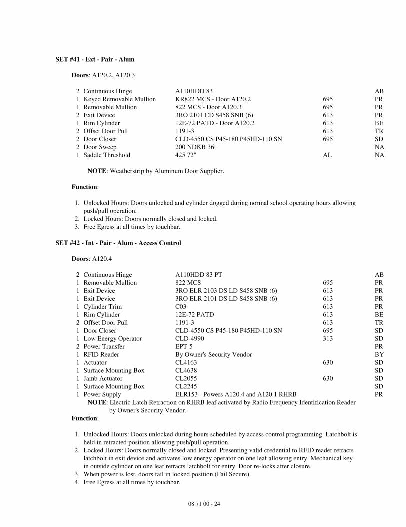
SET #41 - Ext - Pair - Alum
Doors: A120.2, A120.3
2 Continuous Hinge A110HDD 83 AB
1 Keyed Removable Mullion KR822 MCS - Door A120.2 695 PR
1 Removable Mullion 822 MCS - Door A120.3 695 PR
2 Exit Device 3RO 2101 CD S458 SNB (6) 613 PR
1 Rim Cylinder 12E-72 PATD - Door A120.2 613 BE
2 Offset Door Pull 1191-3 613 TR
2 Door Closer CLD-4550 CS P45-180 P45HD-110 SN 695 SD
2 Door Sweep 200 NDKB 36" NA
1 Saddle Threshold 425 72" AL NA
NOTE: Weatherstrip by Aluminum Door Supplier.
Function:
1. Unlocked Hours: Doors unlocked and cylinder dogged during normal school operating hours allowing
push/pull operation.
2. Locked Hours: Doors normally closed and locked.
3. Free Egress at all times by touchbar.
SET #42 - Int - Pair - Alum - Access Control
Doors: A120.4
2 Continuous Hinge A110HDD 83 PT AB
1 Removable Mullion 822 MCS 695 PR
1 Exit Device 3RO ELR 2103 DS LD S458 SNB (6) 613 PR
1 Exit Device 3RO ELR 2101 DS LD S458 SNB (6) 613 PR
1 Cylinder Trim C03 613 PR
1 Rim Cylinder 12E-72 PATD 613 BE
2 Offset Door Pull 1191-3 613 TR
1 Door Closer CLD-4550 CS P45-180 P45HD-110 SN 695 SD
1 Low Energy Operator CLD-4990 313 SD
2 Power Transfer EPT-5 PR
1 RFID Reader By Owner's Security Vendor BY
1 Actuator CL4163 630 SD
1 Surface Mounting Box CL4638 SD
1 Jamb Actuator CL2055 630 SD
1 Surface Mounting Box CL2245 SD
1 Power Supply ELR153 - Powers A120.4 and A120.1 RHRB PR
NOTE: Electric Latch Retraction on RHRB leaf activated by Radio Frequency Identification Reader
by Owner's Security Vendor.
Function:
1. Unlocked Hours: Doors unlocked during hours scheduled by access control programming. Latchbolt is
held in retracted position allowing push/pull operation.
2. Locked Hours: Doors normally closed and locked. Presenting valid credential to RFID reader retracts
latchbolt in exit device and activates low energy operator on one leaf allowing entry. Mechanical key
in outside cylinder on one leaf retracts latchbolt for entry. Door re-locks after closure.
3. When power is lost, doors fail in locked position (Fail Secure).
4. Free Egress at all times by touchbar.

08 71 00 - 25
SET #43 - Ext - Pair - Access Control - Alum
Doors: A120.1
1 Continuous Hinge A110HDD 83 PT AB
1 Continuous Hinge A110HDD 83 AB
1 Removable Mullion 822 MCS 695 PR
1 Exit Device 3RO 2101 CD S458 SNB (6) 613 PR
1 Exit Device 3RO ELR 2103 CD DS S458 SNB (6) 613 PR
1 Cylinder Trim C03 613 PR
1 Rim Cylinder 12E-72 PATD 613 BE
2 Offset Door Pull 1191-3 613 TR
1 Door Closer CLD-4550 CS P45-180 P45HD-110 SN 695 SD
1 Low Energy Operator CLD-4990 313 SD
1 Power Transfer EPT-5 PR
1 RFID Reader By Owner's Security Vendor BY
1 Actuator CL4163 630 SD
1 Surface Mounting Box CL4638 SD
2 Door Sweep 200 NDKB 36" NA
1 Saddle Threshold 425 72" AL NA
NOTE: Weatherstrip by Aluminum Door Supplier.
Electric Latch Retraction on RHRB leaf activated by Radio Frequency Identification Reader
by Owner's Security Vendor.
Function:
1. Unlocked Hours: Doors unlocked and cylinder dogged during normal school operating hours allowing
push/pull operation. Operation by pushing actuator plates on either side of one leaf to activate low
energy operator for entry /exit.
2. Locked Hours: Doors normally closed and locked. Presenting valid credential to RFID reader retracts
latchbolt in exit device and activates low energy operator on one leaf allowing entry. Mechanical key
in outside cylinder on one leaf retracts latchbolt for entry. Door re-locks after closure.
3. When power is lost, doors fail in locked position (Fail Secure).
4. Free Egress at all times by touchbar.
SET #44 - Ovh Coiling Doors
Doors: A114.2, A127.2, B101.3, B102.1
1 Rim Cylinder 12E-72 PATD 626 BE
SET #45 - Gates - Double
1 Padlock 11B-772L PATD M1 WC 626 BE
ALL OTHER HARDWARE BY GATE MFR. BY
Gate Hinges
Cane Bolts
Latch for Padlock
SET #46 - Gates - Single
ALL HARDWARE BY GATE MFR. BY
Gate Hinges
Gate Latch

08 71 00 - 26
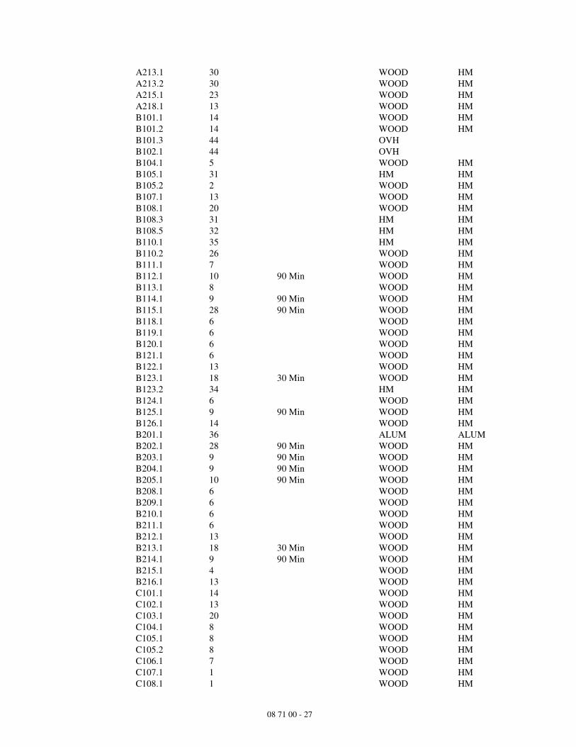
Opening List
Opening Hdw Set Opening Label Door Type Frame Type
A101.1 38 ALUM ALUM
A101.2 37 ALUM ALUM
A102.1 4 WOOD HM
A103.1 19 WOOD HM
A104.1 2 WOOD HM
A105.1 11 WOOD HM
A105.2 14 WOOD HM
A106.1 5 WOOD HM
A108.1 5 WOOD HM
A110.1 8 WOOD HM
A111.1 7 WOOD HM
A113.1 4 WOOD HM
A114.1 14 WOOD HM
A114.2 44 OVH
A115.1 6 WOOD HM
A116.1 8 WOOD HM
A117.1 13 WOOD HM
A118.1 17 WOOD
A119.1 11 WOOD HM
A119.2 15 WOOD HM
A120.1 43 ALUM ALUM
A120.2 41 ALUM ALUM
A120.3 41 ALUM ALUM
A120.4 42 ALUM ALUM
A120.5 40 ALUM ALUM
A120.6 40 ALUM ALUM
A124.1 22 30 Min WOOD HM
A125.1 20 WOOD HM
A127.1 14 WOOD HM
A127.2 44 OVH
A128.1 29 WOOD HM
A128.2 27 WOOD HM
A128.3 27 WOOD HM
A128.4 27 WOOD HM
A129.1 14 WOOD HM
A130.1 2 WOOD HM
A131.1 14 WOOD HM
A132.1 13 WOOD HM
A133.1 30 WOOD HM
A136.1 30 WOOD HM
A137.1 22 30 Min WOOD HM
A201.1 14 WOOD HM
A203.1 24 WOOD HM
A205.1 5 WOOD HM
A206.1 5 WOOD HM
A207.1 14 WOOD HM
A208.1 14 WOOD HM
A209.1 13 WOOD HM
A210.1 13 WOOD HM
A211.1 25 WOOD HM
08 71 00 - 27
A213.1 30 WOOD HM
A213.2 30 WOOD HM
A215.1 23 WOOD HM
A218.1 13 WOOD HM
B101.1 14 WOOD HM
B101.2 14 WOOD HM
B101.3 44 OVH
B102.1 44 OVH
B104.1 5 WOOD HM
B105.1 31 HM HM
B105.2 2 WOOD HM
B107.1 13 WOOD HM
B108.1 20 WOOD HM
B108.3 31 HM HM
B108.5 32 HM HM
B110.1 35 HM HM
B110.2 26 WOOD HM
B111.1 7 WOOD HM
B112.1 10 90 Min WOOD HM
B113.1 8 WOOD HM
B114.1 9 90 Min WOOD HM
B115.1 28 90 Min WOOD HM
B118.1 6 WOOD HM
B119.1 6 WOOD HM
B120.1 6 WOOD HM
B121.1 6 WOOD HM
B122.1 13 WOOD HM
B123.1 18 30 Min WOOD HM
B123.2 34 HM HM
B124.1 6 WOOD HM
B125.1 9 90 Min WOOD HM
B126.1 14 WOOD HM
B201.1 36 ALUM ALUM
B202.1 28 90 Min WOOD HM
B203.1 9 90 Min WOOD HM
B204.1 9 90 Min WOOD HM
B205.1 10 90 Min WOOD HM
B208.1 6 WOOD HM
B209.1 6 WOOD HM
B210.1 6 WOOD HM
B211.1 6 WOOD HM
B212.1 13 WOOD HM
B213.1 18 30 Min WOOD HM
B214.1 9 90 Min WOOD HM
B215.1 4 WOOD HM
B216.1 13 WOOD HM
C101.1 14 WOOD HM
C102.1 13 WOOD HM
C103.1 20 WOOD HM
C104.1 8 WOOD HM
C105.1 8 WOOD HM
C105.2 8 WOOD HM
C106.1 7 WOOD HM
C107.1 1 WOOD HM
C108.1 1 WOOD HM

08 71 00 - 28
C109.1 7 WOOD HM
C110.1 14 WOOD HM
C111.1 34 HM HM
C112.1 28 90 Min WOOD HM
C113.1 9 90 Min WOOD HM
C114.1 5 WOOD HM
C117.1 33 HM HM
C118.1 13 WOOD HM
C119.1 6 WOOD HM
C120.1 6 WOOD HM
C121.1 6 WOOD HM
C122.1 6 WOOD HM
C123.1 6 WOOD HM
C124.1 13 WOOD HM
C125.1 18 30 Min WOOD HM
C125.2 34 HM HM
C126.1 9 90 Min WOOD HM
C127.1 20 WOOD HM
C128.1 37 ALUM ALUM
C128.2 39 ALUM ALUM
C201.1 14 WOOD HM
C202.1 8 WOOD HM
C203.1 10 90 Min WOOD HM
C204.1 7 WOOD HM
C205.1 27 WOOD HM
C205.2 27 WOOD HM
C205.3 27 WOOD HM
C206.1 12 WOOD HM
C207.1 12 WOOD HM
C209.1 10 90 Min WOOD HM
C210.1 9 90 Min WOOD HM
C211.1 9 90 Min WOOD HM
C212.1 28 90 Min WOOD HM
C215.1 6 WOOD HM
C216.1 6 WOOD HM
C217.1 6 WOOD HM
C218.1 6 WOOD HM
C219.1 13 WOOD HM
C220.1 18 30 Min WOOD HM
C221.1 6 WOOD HM
C222.1 21 WOOD HM
D101.1 28 90 Min WOOD HM
D102.1 9 90 Min WOOD HM
D103.1 4 WOOD HM
D104.1 18 30 Min WOOD HM
D104.2 34 HM HM
D105.1 13 WOOD HM
D106.1 6 WOOD HM
D107.1 6 WOOD HM
D108.1 6 WOOD HM
D109.1 6 WOOD HM
D112.1 9 90 Min WOOD HM
D113.1 9 90 Min WOOD HM
D114.1 10 90 Min WOOD HM
D115.1 3 WOOD HM

08 71 00 - 29
D115.2 3 WOOD HM
D116.1 5 WOOD HM
D201.1 28 90 Min WOOD HM
D202.1 6 WOOD HM
D203.1 18 30 Min WOOD HM
D204.1 13 WOOD HM
D205.1 6 WOOD HM
D206.1 6 WOOD HM
D207.1 6 WOOD HM
D208.1 6 WOOD HM
D211.1 9 90 Min WOOD HM
D212.1 9 90 Min WOOD HM
D213.1 10 90 Min WOOD HM

Page Intentionally Left Blank