SECTION 00 0101 - PROJECT TITLE PAGE SAINT LOUIS ZOO ...
227
Chiodini Architects Saint Louis Zoo - Stingray LSS Building Project Number: 2020.020 Missouri,St Louis Project Title Page 00 0101 - 1 SECTION 00 0101 - PROJECT TITLE PAGE SAINT LOUIS ZOO STINGRAY LIFE SUPPORT SYSTEMS BUILDING ARCHITECTS PROJECT NUMBER: 2020.020 OWNERS PROJECT NUMBER: 097_STINGRAY LSS BUILDING_2021 SAINT LOUIS ZOO FOREST PARK CAMPUS GOVERNMENT DRIVE ST LOUIS , MISSOURI 63110 DATE: 04-26-2021 PREPARED BY: CHIODINI ARCHITECTS END OF SECTION
Transcript of SECTION 00 0101 - PROJECT TITLE PAGE SAINT LOUIS ZOO ...

Chiodini ArchitectsSaint Louis Zoo - Stingray LSS
BuildingProject Number: 2020.020 Missouri,St Louis
Project Title Page 00 0101 - 1
SECTION 00 0101 - PROJECT TITLE PAGESAINT LOUIS ZOO
STINGRAY LIFE SUPPORT SYSTEMS BUILDING
ARCHITECTS PROJECT NUMBER: 2020.020
OWNERS PROJECT NUMBER: 097_STINGRAY LSS BUILDING_2021
SAINT LOUIS ZOO
FOREST PARK CAMPUS
GOVERNMENT DRIVE
ST LOUIS , MISSOURI 63110
DATE: 04-26-2021
PREPARED BY:
CHIODINI ARCHITECTS
END OF SECTION
Chiodini ArchitectsSaint Louis Zoo - Stingray LSS
BuildingProject Number: 2020.020 Missouri,St Louis
Seals Page 00 0107 - 1
SECTION 00 0107 - SEALS PAGE
CHIODINI ARCHITECTS
1401 BRENTWOOD BLVD
SUITE 575
ST LOUIS, MO 63144
CIVIL DESIGNS INC
5220 OAKLAND AVE
ST LOUIS, MO 63110
END OF SECTION
mjedwards
Image
mjedwards
Image
Chiodini ArchitectsSaint Louis Zoo - Stingray LSS
BuildingProject Number: 2020.020 Missouri,St Louis
Table of Contents 00 0110 - 1
SECTION 00 0110 - TABLE OF CONTENTSPROCUREMENT AND CONTRACTING REQUIREMENTS
1.1 DIVISION 00 -- PROCUREMENT AND CONTRACTING REQUIREMENTS A. 00 0101 - Project Title PageB. 00 0107 - Seals PageC. 00 0115 - List of Drawing SheetsD. Saint Louis Zoo Procurement and Contracting Requirements
1. Scope of Work2. Request for Bid Proposal and Requirements3. Bid Form, Prevailing Wage Order, Sales/Use Tax Exemption Letter & Certificate4. Zoo Policy Reguarding Participation of DBE in Construction Projects
E. Zoo Contract SampleF. Structural Calculations
SPECIFICATIONS
2.1 DIVISION 01 -- GENERAL REQUIREMENTS A. 01 1000 - SummaryB. 01 2000 - Price and Payment ProceduresC. 01 2200 - Unit PricesD. 01 2300 - AlternatesE. 01 2500 - Substitution ProceduresF. 01 3000 - Administrative RequirementsG. 01 4000 - Quality RequirementsH. 01 5000 - Temporary Facilities and ControlsI. 01 6000 - Product RequirementsJ. 01 6116 - Volatile Organic Compound (VOC) Content RestrictionsK. 01 7000 - Execution and Closeout RequirementsL. 01 7419 - Construction Waste Management and Disposal
2.2 DIVISION 02 -- EXISTING CONDITIONS A. 02 4100 - Demolition
2.3 DIVISION 03 -- CONCRETE A. See Structural Drawings
2.4 DIVISION 04 -- MASONRY (NOT USED) 2.5 DIVISION 05 -- METALS
A. See Structural Drawings2.6 DIVISION 06 -- WOOD, PLASTICS, AND COMPOSITES
A. 06 1000 - Rough CarpentryB. 06 8316 - Fiberglass Reinforced Paneling
2.7 DIVISION 07 -- THERMAL AND MOISTURE PROTECTION A. 07 1113 - Bituminous DampproofingB. 07 2100 - Thermal InsulationC. 07 2500 - Weather BarriersD. 07 4113 - Metal Roof PanelsE. 07 4213 - Metal Wall PanelsF. 07 4214 - Insulated Metal Wall PanelsG. 07 6200 - Sheet Metal Flashing and TrimH. 07 9200 - Joint Sealants
2.8 DIVISION 08 -- OPENINGS

Chiodini ArchitectsSaint Louis Zoo - Stingray LSS
BuildingProject Number: 2020.020 Missouri,St Louis
Table of Contents 00 0110 - 2
A. 08 1113 - Hollow Metal Doors and FramesB. 08 1613 - Fiberglass DoorsC. 08 5413 - Fiberglass WindowsD. 08 7100 - Door Hardware
2.9 DIVISION 09 -- FINISHES A. 09 2116 - Gypsum Board AssembliesB. 09 7733 - Glass Fiber Reinforced Plastic PanelsC. 09 9000 - Painting and Coating
2.10 DIVISION 10 -- SPECIALTIES A. 10 2800 - Toilet, Bath, and Laundry AccessoriesB. 10 5126 - Plastic LockersC. 10 7313 - Awnings
2.11 DIVISION 11 -- EQUIPMENT 2.12 DIVISION 12 -- FURNISHINGS (NOT USED) 2.13 DIVISION 13 -- SPECIAL CONSTRUCTION (NOT USED) 2.14 DIVISION 14 -- CONVEYING EQUIPMENT (NOT USED) 2.15 DIVISION 21 -- FIRE SUPPRESSION (NOT USED) 2.16 DIVISION 22 -- PLUMBING
A. See Plumbing Drawings2.17 DIVISION 23 -- HEATING, VENTILATING, AND AIR-CONDITIONING (HVAC)
A. See Mechanical Drawings2.18 DIVISION 25 -- INTEGRATED AUTOMATION (NOT USED) 2.19 DIVISION 26 -- ELECTRICAL
A. See Electrical D2.20 DIVISION 27 -- COMMUNICATIONS
A. See Electrical Drawings2.21 DIVISION 28 -- ELECTRONIC SAFETY AND SECURITY
A. See Electrical Drawings2.22 DIVISION 31 -- EARTHWORK
A. 31 1000 - Site ClearingB. 31 2300 - Excavation and Fill
2.23 DIVISION 32 -- EXTERIOR IMPROVEMENTS A. 32 1123 - Aggregate Base CoursesB. 32 1216 - Asphalt PavingC. 32 1313 - Concrete Paving
2.24 DIVISION 33 -- UTILITIES A. 33 1116 - Site Water Utility Distribution PipingB. 33 3100 - Sanitary Utility Sewerage PipingC. 33 4100 - Storm Utility Drainage Piping
Chiodini ArchitectsSaint Louis Zoo - Stingray LSS
BuildingProject Number: 2020.020 Missouri,St Louis
List of Drawing Sheets 00 0115 - 1
SECTION 00 0115 - LIST OF DRAWING SHEETSPART 1 - GENERAL
1.1 WORK INCLUDESA. Contract Documents - Drawings
1. Refer to G001 - Cover for drawings indexPART 2 - PRODUCTS (NOT USED)
PART 3 - EXECUTIOIN (NOT USED)
END OF SECTION
1
Project Name:Stingray Life Support Systems Building RFP 2021
Issue for Bid
Project Manual
Date: April 28, 2021
Candace BinghamDirector of ProcurementSaint Louis ZooOne Government DriveSt. Louis, MO [email protected]
2
TABLE OF CONTENTS
Invitation to Bid ............................................................................................................................3
Request for Bid Proposal
The Bidding Process..............................................................................................................4
Selection of Successful Bidder and Contract Award .............................................................6
Insurance Requirements........................................................................................................7
Payment Applications..................................................................................................9
Architectural Seal, Permits, Code Compliance ...............................................................9
Drawings, Photos, and Correspondence ......................................................................10
Contractor’s Responsibilities ...............................................................................................10
Guarantee............................................................................................................................10
General Zoo Requirements .................................................................................................10
Appendix A Stipulated Bid Form..........................................................................................13
Appendix B Prevailing Wage Order ......................................................................................19
Appendix C Sales/Use Tax Exemption Letter and Certificate .............................................23
Appendix D Zoo Policy Regarding Participation of DBE in Construction Projects...............24
3
INVITATION TO BIDDERS
PROJECT:Stingray Life Support Systems Building RFP 2021
SCOPE OF WORK: Replace existing Saint Louis Zoo stingray life support systems concrete slab and tent structure with a new Life Support Systems Building
MANDATORY PRE-BID MEETING & SITE INSPECTION:Prebid Meeting: Wednesday May 5, 2021 at 9:00 AM CST via Zoom meeting. To access: Register in advance for this meeting.
https://stlzoo.zoom.us/meeting/register/tZUtfuyurzstH9YeI4FaO9J5mmAuqwxU4ft_ After registering, you will receive a confirmation email containing information about
joining the meeting.On-site Inspection: Thursday May 6, 2021 at 9:00 AM CST in the in the Saint Louis Zoo Living World lower level rotunda (North Zoo Entrance).
BID DOCUMENTS: Bid Documents will be available on April 28, 2021 at: stlzoo.org/vendor
Note: Failure to include a completed MBE/WBE participation form will result in participation recorded as ZERO at bid opening.
PROPOSAL QUESTIONS: All questions must be received by Wednesday May 12, 2021 at 5:00 PM CST for issuing of addenda. Addenda will be placed on the Zoo website as they become available: stlzoo.org/vendor
BID DATE:Proposals accepted on or before Wednesday May 19, 2021 at 2:00 PM CST, Documents must be uploaded to the below link. Copy/paste the following link into your browser to upload: https://stlzoopoc.egnyte.com/ul/7Cb7piXAI9 To ensure ease of submission, consider uploading well ahead of the deadline time. Late submissions will not be accepted.
ZOO CONTACTS:For questions, contact:Candace BinghamDirector of [email protected]

4
REQUEST FOR BIDThe Saint Louis Zoo is seeking competitive proposals from qualified bidders as outlined on the Invitation to bidders, this Request for Proposal, and the Scope of Work contained in these Bid Documents.
I. THE BIDDING PROCESSA. Pre-Bid Meeting and site Inspection/s
1. The Saint Louis Zoo will a have Mandatory Pre-Bid Meeting for all interested Bidders on Wednesday May 5, 2021 at 9:00 AM CST via Zoom meeting. To access: Register in advance for this meeting:https://stlzoo.zoom.us/meeting/register/tZUtfuyurzstH9YeI4FaO9J5mmAuqwxU4ftAfter registering, you will receive a confirmation email containing information about joining the meeting.On Site Inspection: Thursday May 6, 2021 at 9:00 AM CST in the Saint Louis Zoo Living World Lower Level (North Entry) Bids will be accepted only from Contractors who have been in business for five (5) years or more and have attended the Pre-Bid Meeting.
2. Bidders are directed to inspect the site and to investigate all conditions involved in executing a Contract, to carefully read the specifications, to examine the drawings included in these Bid Documents, and to inform themselves fully of the conditions under which the Contract is to be performed. The Contractor will not be allowed additional compensation for items on which he has failed to inform himself prior to the bidding.
3. The submission of a bid will be construed by the Saint Louis Zoo to mean that the Bidder has made such examinations and investigations, and agrees to fulfill all the requirements of the Contract in full accordance with these specifications, and that he/she is entirely familiar with and thoroughly understands all such requirements.
B. Bid Form and Submittal of Proposal1. Note: Failure to include a completed MBE/WBE participation form will
result in participation recorded as NONRESPONSIVE/ DISQUALIFIED at bid opening.
2. Quotations should be typewritten or in ink on Bid Form provided. Altered or erased prices will not be accepted.
3. Bids will be accepted on or before Wednesday May 19, 2021 at 2:00 PM CST Copy/ paste the following link into your browser to upload documents: https://stlzoopoc.egnyte.com/ul/7Cb7piXAI9
4. No bid received after the specified time will be considered.
5
5. Any bid may be withdrawn prior to the specified time for opening bids or any authorized postponement thereof.
6. Bids having an acceptance time limit of less than 30 days may be rejected.7. Mailed, faxed, or phone in bids shall not be accepted. 8. Sunshine Law. “Bidder” acknowledges that Zoo has represented to Bidder that
Zoo may be subject to the provisions of Missouri’s Sunshine Laws (Mo. Rev. Stat. Sects. 610.010-.225) (the “Sunshine Law”), which statute creates a presumptive rule of public availability of all records held by public governmental bodies, such as the Zoo, unless an exemption from disclosure is available under the Sunshine Law (this includes all Bidding Materials that are not exempt from disclosure under the Sunshine Law).
C. Bid Proposal components and Attachments1. Cost(s)
a. A separate cost is required to provide 100% performance and payment bonds for the total cost of this project.
b. The laws of the state of Missouri provide that the Saint Louis Zoo pay not state sales or use tax, or federal excise taxes, and these taxes should be excluded from your bid price. Documentation will be provided for Contractor’s use in making tax-exempt purchases for this project. (Refer to Appendix B).
c. Bids will include cost of delivery to jobsite of all materials.d. Workers’ wages shall be paid in accordance to the Missouri Division of Labor
Standards (Refer to Appendix B).(1) Not less than the prevailing hourly wages, as set out in the Wage Order
attached to and made part of the specification for work under the contract, shall be paid to all workers performing work under the contract. (Section 290.257.2, RSMo).
(2) The contractor will forfeit a penalty to the contracting body of $100 per day (or portion of a day) for each worker that is paid less than the prevailing wage for any work done under the contract by the contractor or by any subcontractor. (Section 290.257.2 RSMo). For detailed information on rules and occupational titles, refer to 8 CSR 30-3.010 through 3.060.
2. Unit Prices (if requested)a. It is understood that the quantities stated in the bid Documents are not
guaranteed by the Zoo and are used solely for the purpose of comparing Bids and awarding the Contract, and may or may not represent the actual quantities encountered on the job. The zoo reserves the right to reduce any or all quantities. The zoo may also add additional components or copies of specified components for which Contractor agrees to do the work at the unit price stated in the Bid or subsequent cost breakdown.
6
b. Bidders must quote unit prices and extensions on each item listed on Bid form (if any). When an error appears in an extension, the unit price will govern.
c. The Saint Louis zoo reserves the right to make a contract award on a per item basis or a total package basis.
D. Safety1. The contractor and all subcontractors to the contract must require all on-site
employees to complete the ten-hour construction safety training program required under Section 292.675,RSMo, unless they have previously completed the program and have documentation of having done so.
2. The contractor will forfeit a penalty to the contracting public body of $2,500 plus an additional $100 for each employee employed by the contractor or subcontractor, for each calendar day, or portion thereof, such employee is employed without the required training (Section 292.675 RSMo).
E. Minority Participation List1. Bidder shall execute and include with Bid Proposal the Minority & Woman
Owned Participation on Saint Louis Zoo Contract attachment to Bid Form (Appendix D).
F. Bid Bond – Not Required.G. Responsibilities of the Bidder for Accuracy of Bid Proposal
1. Bidders may not use omissions or errors in the Bid Documents or other Contract Documents to their advantage. The Owner reserves the right to issue new instructions correcting any such errors or omissions, which new instructions shall be treated as if originally included.
2. The Bid Documents contain the available information about the work and the conditions pertaining thereto. Information obtained from any officer, agent, or employee of the Saint Louis Zoo, or from any other person, will not relieve the Contractor’s responsibility to assume all risks and obligations pertaining to the work, and to fulfill the conditions of the Contract. Bidders are required to satisfy themselves as to the accuracy of the estimated quantities in the Bid Documents, and must thoroughly examine the site and review the Bid Documents, including Addenda, if any, before submitting a Bid.
3. No Bidder may assert after Bids have been opened that there was a misunderstanding concerning the Bid Documents, the conditions under which the work must be performed, or the quantities of work involved.
H. Direct questions about this Request for Bid to: Candace Bingham.
II. SELECTION OF SUCCESSFUL BIDDER AND CONTRACT AWARDA. The Saint Louis Zoo enjoys the support of the community through the Metropolitan
Zoological Park & Museum District. For this reason, the Zoo makes every effort to

7
return that support by contracting with qualified businesses within the District (comprised of St. Louis and St. Louis County) whenever possible.
B. The time specified for awarding a Contract and for commencing work may be extended or shortened by mutual agreement between the Zoo and the successful Bidder.
C. The Zoo reserves the right to waive any informalities or minor defects in the Bid or bidding procedures; to reject any or all Bids; to rebid the project at a later date if Bids are rejected; and to accept the Bid that, in the judgment of the Zoo, will serve the best interests of the Zoo, whether or not said Bid is the low Bid.
D. Before awarding any Contract, the Saint Louis Zoo reserves the right to require the successful Bidder to file proof of his ability to properly finance, manage, staff and execute the project. The Zoo reserves the right to reject any bid if the evidence submitted by, or other investigation of, the Bidder fails to satisfy the Zoo that the Bidder has the proper qualifications, experience, equipment, manpower, or financial and managerial capability to carry out the obligations of the agreement or to perform the work contemplated.
E. Before award of Contract Successful Bidder may be required to furnish:1. Cost breakdown and unit prices2. Proposed schedule3. Information regarding material Subcontractors upon request4. Bonds and insurance certificates
III. INSURANCE REQUIREMENTS
A. Before a Contract is signed, the successful Bidder will be required to furnish certificates of insurance showing that adequate Public Liability and Property Damage Insurance is being carried to protect the Saint Louis Zoo, its employees and officials, the City of St. Louis and the County of St. Louis. All insurance must be kept in force for the life of this Contract.
B. The Contractor shall purchase from and maintain in a company or companies lawfully authorized to do business in the jurisdiction in which the Project is located such insurance as will protect the Contractor from claims set forth below which may arise out of or result from the Contractor’s operations under the Contract and for which the Contractor may be legally liable whether such operations be by the Contractor or by a Subcontractor or by anyone directly or indirectly employed by any of them, or by anyone for whose acts any of them may be liable.1. Claims under workers’ compensation, disability benefit and other similar
employee benefit acts, which are applicable to the work to be performed.2. Claims for damages because of bodily injury, occupational sickness or disease,
or death of the Contractor’s employees.

8
3. Claims for damages because of bodily injury, sickness or disease, or death of any person other than the Contractor’s employees.
4. Claims for damages insured by usual personal injury liability coverage.5. Claims for damages, other than to the work itself, because of injury to or
destruction of tangible property, including loss of use resulting therefrom.6. Claims for damages because of bodily injury, death of a person or property
damage arising out of ownership, maintenance or use of a motor vehicle.7. Claims for bodily injury, property damage arising out of completed operations.8. Claims involving contractual liability insurance applicable to all Contractor
obligations.C. The insurance required shall be written for not less than limits of liability specified in
the Contract Documents or required by law, whichever coverage is greater. Coverage, whether written on an occurrence or claims-made basis, shall be maintained without interruption from date of commencement of the work until date of final payment and termination of any coverage required to be maintained after final payment.1. General Liability
Bodily injury:$1,000,000 each occurrence$2,000,000 aggregate
Property damage
2. Employer's Liability$500,000 each accident$500,000 disease, each employee$1,000,000 disease, policy limit
3. Contractual Liability (Hold Harmless Coverage) Bodily Injury:
$1,000,000 each occurrence$2,000,000 aggregate
Property damage
4. Umbrella Excess Liability$2,000,000 over primary insurance
5. Automobile Liability$1,000,000 combined single limit
6. Owner's Protective Liability Policy in the Owner's Name$1,000,000
9
D. The general liability and the umbrella insurance must be written on an occurrence form versus a claims-made form. Aggregates should apply per project.
E. Certificates of insurance acceptable to the Owner shall be filed with the Owner prior to commencement of the Work. These certificates and the insurance policies required shall contain a provision that coverage afforded under the policies will not be canceled or allowed to expire until at least 30 days’ prior, written notice has been given to the Owner. If any of the foregoing insurance coverage is required to remain in force after final payment and are reasonably available, an additional certificate evidencing continuation of such coverage shall be submitted with the final Application for Payment. Information concerning reduction of coverage on account of revised limits or claims paid under the General Aggregate, or both, shall be furnished by the Contractor with reasonable promptness in accordance with the Contractor’s information and belief.
F. Insurance certificates shall also be provided for any supplier or Subcontractor storing materials for this project for which application for payment is made.
G. The Owner shall be responsible for purchasing and maintaining the Owner’s usual liability insurance. NOTE: OWNER'S INSURANCE COVERAGE HAS A $5000 DEDUCTIBLE FOR THEFT AND VANDALISM.
H. THE SAINT LOUIS ZOO SHOULD BE ADDED TO CONTRACTOR’S INSURANCE POLICY AS AN ADDITIONAL INSURED; AND THIS POLICY SHOULD ACT AS THE PRIMARY INSURANCE POLICY AND BE SO STATED BY THE ENDORSEMENTS.
IV. PAYMENT APPLICATIONSA. All applications for payment will be submitted on a form mutually agreed upon by
Contractor and the Zoo.B. Applications will be submitted on prearranged schedule to be mutually agreed upon
by Contractor and the Zoo.C. Contractor shall supply lien waivers for all labor and material covered by Contract for
this project.D. The Contractor shall be paid 90% of the Contract amount upon completion of the
project. The final 10% of all Contract amount will be paid upon completion and acceptance of all punch-list items and the tendering of appropriate lien waivers, including those of all suppliers.
V. ARCHITECTURAL SEAL, PERMITS, CODE COMPLIANCEA. Drawings and specifications for structures to be designed for this project by the
Contractor (if any), which may be deemed “occupied by the public,” shall require the seal of an architect licensed to do business in the State of Missouri.
B. Contractor will be responsible to satisfy any and all federal, state, and municipal building codes and regulations for the scope of work outlined in the Bid Documents.

10
C. All work shall be designed, fabricated, and installed in accordance with applicable ADA guidelines.
D. Contractor will meet any and all industry standards for the scope of work outlined in these Bid Documents.
VI. DRAWINGS, PHOTOS, AND CORRESPONDENCEA. Contractor will provide the necessary architectural, engineering or shop drawings,
samples and photographs necessary for approval by Zoo personnel.B. The cost of all drawings, specifications, reproduction, samples, illustrations and
photographs shall be included in Base Bid.C. In order to expedite routine correspondence and conserve resources, Contractor
should have the capability to send correspondence as well as photographs and design files via e-mail and accept documents transmitted from the Zoo in Microsoft Word.
D. Drawing and important correspondence shall also be furnished in “hard” copy as appropriate.
VII. CONTRACTOR’S RESPONSIBILITIESA. All applicable laws, ordinances, and rules and regulations of all authorities having
jurisdiction over the work shall apply to the Contract, and shall be observed by the Contractor.
B. The Contractor shall hold harmless the Saint Louis Zoo for the payment of any and all claims arising out of any infringement, alleged infringement, or use of any patent or patented device, article, system, arrangement, materials or process used by him/her in the executing of the Contract.
C. The Contractor shall be responsible for the work of all Subcontractors employed by them and shall keep all work under their control. A complete list of all such Subcontractors shall be submitted to the Saint Louis Zoo prior to commencement of this work.
VIII. GUARANTEEA. The Contractor shall furnish a written guarantee, stating that work performed will be
free from defects of materials and workmanship for a period of (1) one full year following final acceptance and agreeing to repair or replace any such defective work, and all work damaged thereby, at no cost to the Saint Louis Zoo, during the period covered by this warranty.
B. Failure to supply the Zoo with a written warranty will in no way relieve the Contractor of this obligation.
IX. GENERAL ZOO REQUIREMENTSA. Temporary Facilities
11
1. Utilities – Existing electrical power and water service to the construction area is available in the building for construction purposes without cost to the Contractor.
2. Sanitary Facilities – Toilet facilities are available to the Contractor on the Zoo grounds.
B. Signs: No signs shall be erected without the Project Owner’s approval of sign and location.
C. Jobsite Rules and Regulations1. In the event of an emergency on Zoo grounds please call extension 2222. This
is the fastest way to get the help you need. State your name, where you are calling from, describe the emergency and where it is happening, and if there are any injuries. If an animal is involved state what type, how many and where they were last seen. Stay on the line until you are told to hang up. After 5:00 pm, call 4669 or the night ranger cell number at 314-799-3273.
2. Awareness of a courtesy to all Zoo visitors at all times is a firm Zoo policy. All Contractors’ personnel must observe this policy.
3. Construction personnel must stay within the confines of designated work areas at all times.
4. Construction personnel are at no time permitted to interfere with or touch the animals or interfere with the keeper-related activities.
5. Construction personnel are at no time permitted to interfere with the public on the Zoo premises. No public display in any form or manner will be tolerated.
6. Construction personnel shall wear proper working attire at all times.7. Construction personnel shall comply with OSHA rules while on the jobsite.8. Normal work hours at the Zoo are 8:00 a.m. to 5:00 p.m., Monday through Friday.
Access to work areas cannot be before 8:00 a.m. or after 5:00 p.m. unless previously arranged and only after approval of the Owner’s Representative.
9. In order to provide maximum safety to the Contractor’s personnel and to protect the animals, close coordination of activities with Zoo personnel is imperative.
10. Access to the site shall be as directed by Zoo’s Project Manager. Employees shall arrive in a crew truck or on foot. Access for employees’ personal vehicles will not be allowed on the grounds (see Parking).
11. All gates must be kept closed and locked at all times. Unlocked and/ or unattended gates will result in a fine to the Contractor of $500 per occurrence.
D. Parking and Access to Zoo Grounds1. Contractor's personnel will be allowed to park on the South Parking Lot. Parking
in the oversized parking spots is not permitted as they are reserved for busses and oversized vehicles. If the entrance to the lot is manned, personnel should identify themselves and sign in.
12
2. Private vehicles are not allowed on the Zoo grounds. If it is necessary to bring private vehicles on the grounds to execute the work called for in these Bid Documents, prior arrangements must be made with the Project Manager. Parking will be allowed only at specified areas. Owners of vehicles must furnish proof of Public Liability and Property Damage Insurance before being allowed to bring their vehicles on the grounds. The maximum speed limit on the Zoo grounds is 5 mph and extreme caution must be used while driving on the grounds.
3. It is the Contractor’s responsibility to advise all on-side employees, subcontractors and material suppliers of these rules and regulations.
4. During the Zoo’s peak visitor’s season, no full-size vehicles of any kind are allowed access to the public paths and roads. All deliveries of material and equipment must be made before 9:00 a.m. and after 5:00 p.m.
E. Material Delivery and Storage1. All firms performing work on the Zoo grounds must schedule that work and
delivery of materials with the Project Manager.2. All deliveries must be scheduled in order to have vehicles off Zoo grounds and
pathways by 9:00 a.m.3. Deliveries must be accompanied by a packing slip or invoice listing the Zoo
Purchase Order Number, if any, and the Project Name, and exact contents and quantities of each item included in the shipment.
4. Only a minimum number of vehicles necessary to accomplish the work will be allowed on the job site. The 5 mph speed limit within the Zoo shall be strictly observed, and every possible consideration shall be given to the public.
5. Materials shall be protected from the elements and stored in strict accordance with the manufacturer’s written recommendations and in locations approved by the Owner. Materials, equipment and personnel for roofing operations shall be arranged on the roof so that a 20-pound-per-square-foot load shall not be exceeded.
F. Barricades, Chutes, and Enclosures1. Furnish and install all barricades are required to protect the public, Zoo
employees and contractors. Provide chutes and enclosures to contain debris and excessive dust.
G. Job Conditions1. Contractor will conduct all operations in such a way as to prevent injury to
buildings, structures, other facilities, landscaping, persons, and animals.2. Contractor shall be responsible for all cleanup and removal from site for disposal
of all debris, packaging, and leftover material. If material is to be disposed of on the Zoo site, prior arrangements must be made with Zoo staff and disposal must follow Zoo regulations and procedures, including sorting and recycling all recyclable material.
13
APPENDIX A
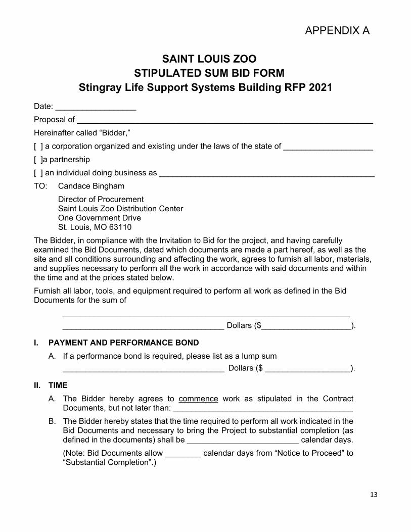
SAINT LOUIS ZOOSTIPULATED SUM BID FORM
Stingray Life Support Systems Building RFP 2021Date: __________________Proposal of __________________________________________________________________Hereinafter called “Bidder,”[ ] a corporation organized and existing under the laws of the state of ____________________[ ]a partnership[ ] an individual doing business as ________________________________________________TO: Candace Bingham
Director of ProcurementSaint Louis Zoo Distribution CenterOne Government DriveSt. Louis, MO 63110
The Bidder, in compliance with the Invitation to Bid for the project, and having carefully examined the Bid Documents, dated which documents are made a part hereof, as well as the site and all conditions surrounding and affecting the work, agrees to furnish all labor, materials, and supplies necessary to perform all the work in accordance with said documents and within the time and at the prices stated below.Furnish all labor, tools, and equipment required to perform all work as defined in the Bid Documents for the sum of
________________________________________________________________ ____________________________________ Dollars ($____________________).
I. PAYMENT AND PERFORMANCE BONDA. If a performance bond is required, please list as a lump sum
____________________________________ Dollars ($ ___________________).
II. TIMEA. The Bidder hereby agrees to commence work as stipulated in the Contract
Documents, but not later than: ________________________________________B. The Bidder hereby states that the time required to perform all work indicated in the
Bid Documents and necessary to bring the Project to substantial completion (as defined in the documents) shall be _________________________ calendar days.(Note: Bid Documents allow ________ calendar days from “Notice to Proceed” to “Substantial Completion”.)

14
III. UNIT PRICESBidder shall price Project on a unit price basis as specified in the Bid Documents Scope of Work, at rates specified herein:
A. Unit Price 01 – Removal of Unsuitable Soils1. Sum: _________________ (Add/Deduct)2. Units: Cubic Yard
B. Unit Price 02 – Removal of Rock1. Sum: _________________ (Add/Deduct)2. Units: Cubic Yard
IV. ALTERNATESBidder shall price Project alternates as specified in the Bid Documents Scope of Work, as added to or deducted from the bid amounts and as added to or deducted from the construction days:
A. Alternate 01 – Epoxy Coated Foundation Reinforcement1. Sum: _________________ (Add/Deduct)2. Days: _________________ (Add/Deduct)
B. Alternate 02 – Fiberglass Truss and Deck Resin1. Sum: _________________ (Add/Deduct)2. Days: _________________ (Add/Deduct)
C. Alternate 03 – Interior FRP Faced Insulated Metal Wall Panel1. Sum: _________________ (Add/Deduct)2. Days: _________________ (Add/Deduct)
D. Alternate 04 – Fiberglass Doors and Frames1. Sum: _________________ (Add/Deduct)2. Days: _________________ (Add/Deduct)
E. Alternate 05 – Electric Air Curtains1. Sum: _________________ (Add/Deduct)2. Days: _________________ (Add/Deduct)

15
V. SUBCONTRACTORS
A. The Bidder hereby indicates that the following Subcontractors and/or Suppliers shall be employed under contract with Bidder for this Project (subject to Owner review and approval).
Work to be Performed Name of Subcontractor
VI. BID DOCUMENTSBidder acknowledges review of the following documents:
A. Specifications
B. Drawings
C. Addendum No. _______________ Dated _______________________________
Addendum No. _______________ Dated _______________________________
Addendum No. _______________ Dated _______________________________
Addendum No. _______________ Dated _______________________________
Addendum No. _______________ Dated _______________________________
Addendum No. _______________ Dated _______________________________
16
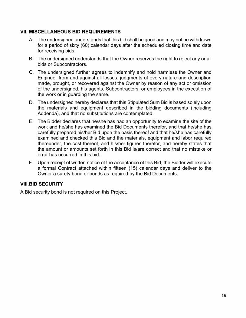
VII. MISCELLANEOUS BID REQUIREMENTSA. The undersigned understands that this bid shall be good and may not be withdrawn
for a period of sixty (60) calendar days after the scheduled closing time and date for receiving bids.
B. The undersigned understands that the Owner reserves the right to reject any or all bids or Subcontractors.
C. The undersigned further agrees to indemnify and hold harmless the Owner and Engineer from and against all losses, judgments of every nature and description made, brought, or recovered against the Owner by reason of any act or omission of the undersigned, his agents, Subcontractors, or employees in the execution of the work or in guarding the same.
D. The undersigned hereby declares that this Stipulated Sum Bid is based solely upon the materials and equipment described in the bidding documents (including Addenda), and that no substitutions are contemplated.
E. The Bidder declares that he/she has had an opportunity to examine the site of the work and he/she has examined the Bid Documents therefor, and that he/she has carefully prepared his/her Bid upon the basis thereof and that he/she has carefully examined and checked this Bid and the materials, equipment and labor required thereunder, the cost thereof, and his/her figures therefor, and hereby states that the amount or amounts set forth in this Bid is/are correct and that no mistake or error has occurred in this bid.
F. Upon receipt of written notice of the acceptance of this Bid, the Bidder will execute a formal Contract attached within fifteen (15) calendar days and deliver to the Owner a surety bond or bonds as required by the Bid Documents.
VIII.BID SECURITYA Bid security bond is not required on this Project.
17
By signing The Bidder hereby states to perform all work indicated in the Bid Documents and necessary to bring the Project to completion.
IF A CORPORATION
Name of Corporation Signature of Officer
Incorporated under the laws of the state of Name and Title of Officer (Print or Type)
Licensed to do business in Missouri? Address for Communications:
(Check one) [ ] Yes [ ] No
(Seal if Bid is by corporation)
IF A PARTNERSHIP State Name and Address of ALL Partners:
Name of Partnership
Signature of Authorized Partner
IF INDIVIDUAL Address for Communications: Name of Firm (if any) Signature of Individual Print Name
IF BIDDING AS A JOINT VENTURE (List all parties)

18
EMAIL ADDRESS:
Signature for the Saint Louis Zoo
Saint Louis Zoo
Signature of Officer
Name and Title (Print)
Address for Communications:
1 Government Drive St. Louis, MO 63110
19
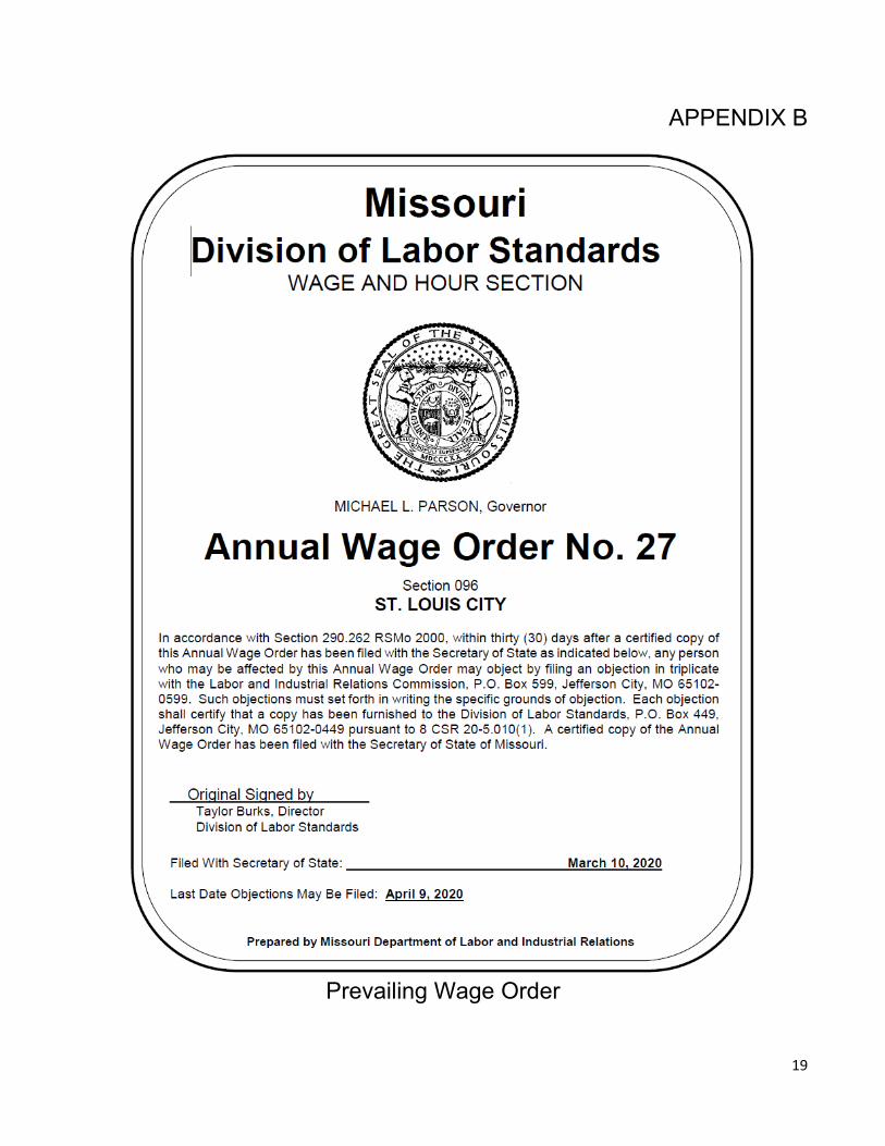
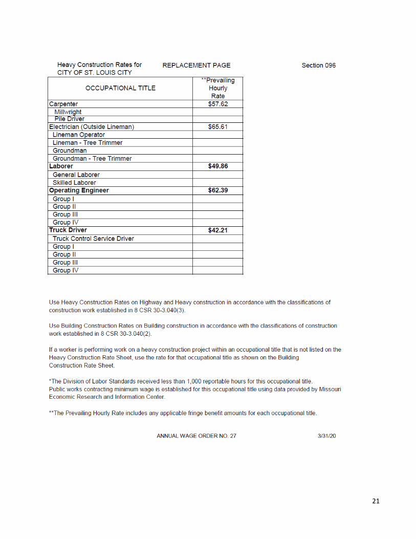
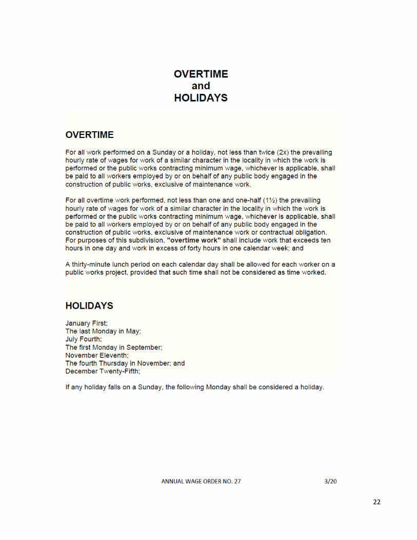
APPENDIX B
Prevailing Wage Order

20
21
22
23
APPENDIX C
State of Missouri EXEMPTION FROM MISSOURI SALES AND USE TAX ON PURCHASES
Issued to: Missouri Tax ID Number: 12623491
Issued to Missouri Tax ID Number 12623491
Any alteration to this exemption letter renders it invalid.
If you have any questions regarding the use of this letter, please contact the Division of Taxation and Collection, P.O. Box 3300, Jefferson City, MO 65105-3300, phone 573-751-2836.
24
APPENDIX D
POLICY ONMINORITY & WOMAN
OWNED BUSINESS PARTICIPATION ONSAINT LOUIS ZOO
CONTRACTS
Revised 3/9/2021

25
POLICY ONMINORITY AND WOMAN OWNED BUSINESS
PARTICIPATION ONSAINT LOUIS ZOO CONTRACTS
SECTION ONE: DEFINITIONSFor purposes of this policy, the following terms have the meanings indicated below:1. Minority Business Enterprise (MBE): a sole proprietorship, partnership or corporation owned, operated and controlled by minority group members who have at least 51% ownership. The minority group member(s) must have day-to-day operational and managerial control and an interest in capital and earnings commensurate with his or her percentage of ownership.2. Minority Group Member(s): persons legally residing in the United States who are African American, Asian-American, Native-American or Hispanic-American.3. Women’s Business Enterprise (WBE): a sole proprietorship, partnership or corporation owned, operated and controlled by a woman or women who have at least 51% ownership. The woman or women must have day to day operational and managerial control and an interest in capital and earnings commensurate with her or their percentage of ownership.4. Certification: The process by which the Saint Louis Zoo determines a person, firm or legal entity to be a bona fide MBE or WBE.5. Contracting Agency: Any Agency or Department making a contract on behalf of the Saint Louis Zoo.
SECTION TWO: POLICYIt is the policy of the Saint Louis Zoo, a political subdivision of the State of Missouri, that minority and women-owned businesses, as defined herein, shall have the maximum opportunity to participate in the performance of contracts or sub-contracts of the Zoo. The Zoo shall take all necessary and reasonable steps to ensure that said businesses have the maximum opportunity to compete for and perform under all Zoo contracts. The Zoo or its Contracting Agencies shall not discriminate on the basis of race, color, national origin or sex in the award and performance of contracts.
The method that the Saint Louis Zoo shall employ to implement this policy is the establishment of a goal of at least 25% Minority Business Enterprise participation and at least 5% Women’s Business Enterprise participation in contracts and purchases wherein Zoo funds are expended. This goal shall be pursued by the programs described below.
26
SECTION THREE: PROGRAM ADMINISTRATION1. The Chief Financial Officer for the Saint Louis Zoo shall be charged with the overall
responsibility for the administration and enforcement of this Zoo Minority and Women Business Enterprise participation policy. The Director of Procurement shall be charged with establishing procedures & implementation for the purpose of monitoring the Zoo’s overall performance with respect to Minority and Women’s Business Enterprise participation. The duties and responsibilities of the Director of Procurement shall include:
a. Developing and distributing a directory of certified MBE’s and WBE’s.b. Reviewing on a regular basis, the progress of the Zoo toward achieving the goals for
the utilization of Minority Business Enterprises and Women’s Business Enterprises and making an annual report in the first quarter of each year to the Zoo Commission, reporting that progress which has been made, together with recommendations as to such further remedial action that should be taken, if any.
c. Monitoring the Zoo throughout the duration of contracts to ensure that all efforts are made to comply with the requirements of this policy.
d. Certifying whether or not the requirements of this policy have been satisfied before contracts are signed or countersigned.
e. The advertisement for bids, if any, shall appear in the Saint Louis Post Dispatch and the Saint Louis American no later than 21 days before bids are due on specific contracting opportunities, except where the contracts are awarded on an emergency basis.
f. All contract solicitations shall include this MBE/WBE policy and any other materials required.
2. It shall be the responsibility of each bidder and proposer to adhere to procedures and provisions set forth in this policy:a. Each bidder and proposer must complete an MBE and WBE Utilization Form and identify
therein its commitment, if any, to utilize MBE’s and WBE’s. Any failure to complete and sign the MBE and WBE Utilization Form will result in the bid or proposal being declared nonresponsive. In the response to an invitation to bid or request for proposal, the bidder or proposer shall include the names of Minority Business Enterprises and Women’s Business Enterprises to whom it intends to award subcontracts, if any, the dollar value of the subcontracts and the scope of work to be performed.
b. It is the bidder’s or proposer’s responsibilities to ensure all MBEs/WBEs projected for use have been certified by Saint Louis Airport Authority or the National Minority Supplier Development Council (NMSDC) prior to bid opening.
c. Whenever additional contract supplements, extra work orders or change orders are made that individually, or in aggregate, increase the total dollar value of the original contract, the contractor shall make every effort to maintain the level of MBE and WBE participation as established in the original contracts.
d. The awardees of a contract must submit a copy of executed agreements with the MBE’s and WBEs being utilized. Awardees will be required to submit MBE/WBE/DBE workforce participation at the end of each month as well as annually at year’s end.
e. The prime contract bidder must declare their workforce demographics upfront at time of the time of bid. Workforce, as defined by the Zoo, is the entire labor pool for a single company including professional and labor staff.
27
f. The prime contract bidder should break its subcontracts down into discrete items or packages that at least some of the MBEs/WBEs in the relevant area may find economically feasible to perform.
g. The prime contract bidder should not deny a subcontract to an otherwise qualified and competitive MBEs/WBEs solely because the latter cannot perform an entire package of related items, but the bidder may deny a request to repackage the work where doing so would jeopardize scheduling or increase that bidder’s cost of performing the original package by more than 5%.
h. The Zoo shall use at least part of any pre-bid meeting to encourage prime contractors and MBEs/WBEs to work together, providing an opportunity for all firms to identify themselves and for all MBEs/WBEs to identify the type(s) of work that they perform. The Zoo should also emphasize that it expects all firms to perform a commercially useful function.
i. The Zoo shall prepare monthly reports concerning its progress in achieving the goals established in this policy.
j. Charge orders whether made individually or in the aggregate, which alters the total dollar value of the original contract must maintain the level of MBE/WBE participation as established in the original contract. If the Contractor is unable to meet its MBE/WBE contractual commitment, it must submit documentation of reasons for failure to meet the goals.
3. Bonding and Insurance
The prime contract bidder should be encouraged not to deny a subcontract to an otherwise qualified and competitive, and if necessary, certified MBE/WBE solely because the latter cannot provide a performance or payment bond for the work, unless the bidder’s bonding is contingent upon bonding for all subcontractors.
4. Written Policy
Independent and apart from its interest in any one project, the prime contract bidder should have a written policy stating that it affirmatively supports subcontracting to MBEs/WBEs, and that bringing such firms into the mainstream of the construction industry is a priority for that firm. This policy shall be made available to the Zoo upon request.
5. Liaison with MBE/WBEs
Independent and apart from its interest in any one project, the prime contract bidder should assign a senior official the responsibility of serving as a liaison between the firm and the MBEs/WBEs in the relevant area.
6. Scope Letter
At least five business days before the date on which bids are due, the MBEs/WBEs should also give the prime contract bidder a scope letter that defines the items that the MBE/WBE would like to perform.
SECTION FOUR: ZOO CONTRACTSThis section shall be applicable to all contracts let for Zoo contracts or improvements.MBE and WBE participation shall be counted in accordance with the following provisions:1. The Zoo may count MBE or WBE participation only expenditures to MBEs and WBEs that
28
perform commercially useful functions in the execution of a contract. An MBE or WBE is considered to perform a commercially useful function when it is responsible for executing a distinct element of the work and carrying out its responsibilities by actually performing, managing and supervising the work involved. To determine whether a MBE or WBE is performing a commercially useful function, the Zoo will evaluate the amount of work subcontracted, industry practices and other relevant factors.
2. The Zoo may count as a MBE or WBE participation the total dollar value of a contract with a MBE or WBE prime contractor less any amount that is subcontracted to non- MBEs/WBEs (including any persons or firms that are identified as MBE and/or WBE but are not so certified by the Saint Louis Airport Authority).
3. The total dollar value of a contract with an enterprise owned and controlled by minority women may be counted as either minority or women’s business participation, but not both. The Zoo must choose which category of participation to which the dollar value is applied. When both MBE and WBE are presented, the Zoo will count towards MBE participation.
4. The Zoo may count as MBE or WBE participation a portion of the total dollar value of a contract with a joint venture equal to the percentage of MBE or WBE participation in the joint venture. The joint venture must be certified by the Saint Louis Zoo and the MBE and WBE participation in the joint venture must be responsible for a clearly defined portion of the work to be performed, equal to a share in the ownership, control, management, responsibility, risks and profits of the joint venture.
5. The Zoo may count toward a bidder’s MBE and WBE goals expenditures for material and supplies obtained from MBE/WBE suppliers and manufacturers, provided that the MBE/WBE assumes the actual and contractual responsibility for the provision of materials and supplies.a. The Zoo may count a bidder’s entire expenditure to a MBE/WBE manufacturer.
Manufacturer is defined as an individual or entity that produces goods from raw materials or substantially alters them before resale.
b. The bidder may count 20% of its expenditures to MBE/WBE suppliers that are not manufactures.
6. The Zoo may count as MBE and WBE participation the entire expenditure to an MBE or WBE supplier, when the supplier:a. Assumes the actual and contractual responsibility for furnishing the supplies and materials;
andb. Is recognized as a distributor by the industry involved in the contracted supplies and
materials; andc. Owns or leases a warehouse, yard, building or whatever other facilities are viewed as
customary or necessary by the industry; andd. Distributes, delivers and services products with their own staff and/or equipment.
7. The Zoo may count as MBE and WBE participation only those firms that have been certified as MBE’s and WBE’s by Saint Louis Airport Authority or the National Minority Supplier Development Council (NMSDC) prior to bid opening. If a firm listed by a bidder in its bid documents has not been so certified as MBE or WBE, the amount of participation it represents will be deducted from the total MBE or WBE participation proposed by the bidder.
8. Joint ventures or mentor-protégé relationships between prime contractors and subcontractors with local MBE and WBE firms are encouraged.
9. Representatives of the Zoo or its designee shall make periodic visits to the project site to verify minority and women’s business enterprise participation and staffing.
29
SECTION FIVE: SERVICE CONTRACTS1. It shall be the goal of each Contracting Agency where anticipated service contracts, including
professional service contracts, for any year exceed the sum of $50,000 in the aggregate that 25% of the aggregate value of contracts awarded each fiscal year be let with MBEs and that 5% of the aggregate value of contracts awarded each fiscal year be let with WBEs.
2. All requests for services, including professional services, shall require proposers to make every good faith effort to utilize minority business enterprises and women’s business enterprises as subcontractors and suppliers whenever possible.
3. Joint ventures or mentor-protégé relationships between prime contractors and subcontractors with local M/WBE firms are encouraged.
4. Participation of MBE/WBE firms located within the Zoo Museum District is preferred (City of St. Louis and St. Louis County, Missouri).
SECTION SIX: SUPPLY CONTRACTS
1. The goal of the Zoo is that 25% of the value of all contacts let and purchases made by the Zoo shall be let or made with MBE’s and that 5% of the value of all contracts let and purchases made by the Zoo shall be made with WBEs.
2. All contracts let by the Zoo for the purchase or lease of materials, equipment, supplies, commodities or services, the estimated cost of which exceeds $10,000, shall be subject to this goal.
3. Joint ventures or mentor-protégé relationships between prime contractors and subcontractors with local M/WBE firms are encouraged.
4. Participation of M/WBE firms located within the ZMD Tax District is preferred.
SECTION SEVEN: QUALIFICATION BASED SELECTION CONTRACTS
1. The submitter is to submit a supplemental form containing actual M/WBE information as project scope is known.
2. It is a requirement that the Zoo subsequently consents to such supplemental M/WBE information before moving forward.
At contract completion, the Zoo shall obtain final documentation of MBE and WBE participation. The Zoo must have complete and acceptable documentation as determined by the Zoo of amounts paid to all project MBE and WBE subcontractors on file before the final payment is made to the prime contractor.
DATED: _____________________________________________
SAINT LOUIS ZOO: ____________________________________
TITLE: ______________________________________________
CONTRACTOR: _______________________________________
COMPANY: __________________________________________
30
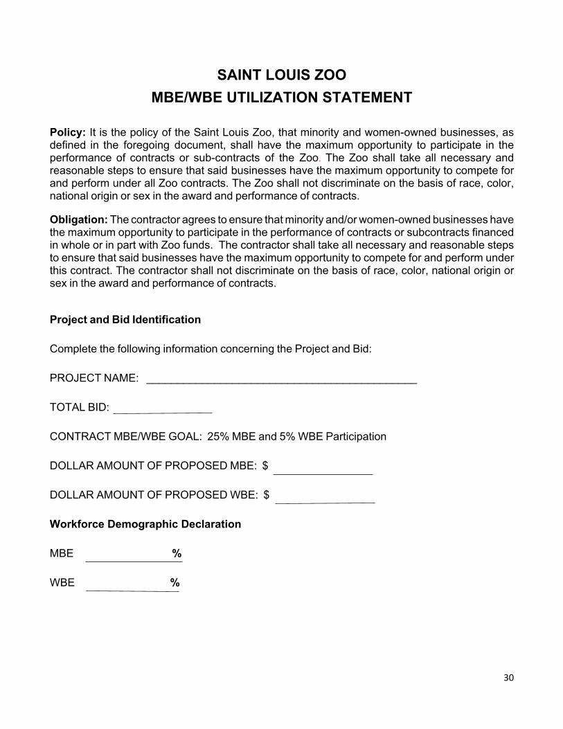
SAINT LOUIS ZOOMBE/WBE UTILIZATION STATEMENT
Policy: It is the policy of the Saint Louis Zoo, that minority and women-owned businesses, as defined in the foregoing document, shall have the maximum opportunity to participate in the performance of contracts or sub-contracts of the Zoo. The Zoo shall take all necessary and reasonable steps to ensure that said businesses have the maximum opportunity to compete for and perform under all Zoo contracts. The Zoo shall not discriminate on the basis of race, color, national origin or sex in the award and performance of contracts.
Obligation: The contractor agrees to ensure that minority and/or women-owned businesses have the maximum opportunity to participate in the performance of contracts or subcontracts financed in whole or in part with Zoo funds. The contractor shall take all necessary and reasonable steps to ensure that said businesses have the maximum opportunity to compete for and perform under this contract. The contractor shall not discriminate on the basis of race, color, national origin or sex in the award and performance of contracts.
Project and Bid Identification
Complete the following information concerning the Project and Bid:
PROJECT NAME: ____________________________________________
TOTAL BID: CONTRACT MBE/WBE GOAL: 25% MBE and 5% WBE Participation
DOLLAR AMOUNT OF PROPOSED MBE: $
DOLLAR AMOUNT OF PROPOSED WBE: $
Workforce Demographic Declaration
MBE %
WBE %
31
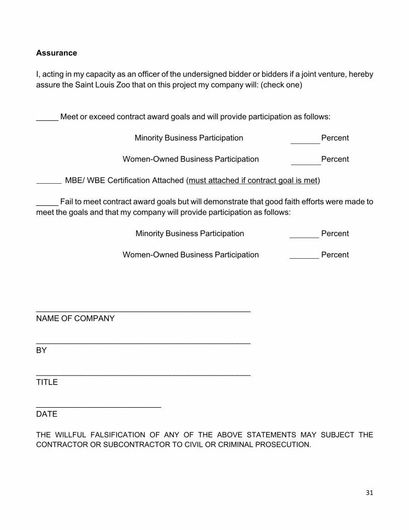
Assurance
I, acting in my capacity as an officer of the undersigned bidder or bidders if a joint venture, hereby assure the Saint Louis Zoo that on this project my company will: (check one)
_____ Meet or exceed contract award goals and will provide participation as follows:
Minority Business Participation Percent
Women-Owned Business Participation Percent
MBE/ WBE Certification Attached (must attached if contract goal is met)
_____ Fail to meet contract award goals but will demonstrate that good faith efforts were made to meet the goals and that my company will provide participation as follows:
Minority Business Participation Percent
Women-Owned Business Participation Percent
________________________________________________NAME OF COMPANY
________________________________________________BY ________________________________________________TITLE
____________________________DATE
THE WILLFUL FALSIFICATION OF ANY OF THE ABOVE STATEMENTS MAY SUBJECT THE CONTRACTOR OR SUBCONTRACTOR TO CIVIL OR CRIMINAL PROSECUTION.
AIA®
Document A101TM – 2017Standard Form of Agreement Between Owner and Contractor where the basis of payment is a Stipulated Sum
AIA Document A101™ – 2017. Copyright © 1915, 1918, 1925, 1937, 1951, 1958, 1961, 1963, 1967, 1974, 1977, 1987, 1991, 1997, 2007 and 2017 by The American Institute of Architects. All rights reserved. WARNING: This AIA® Document is protected by U.S. Copyright Law and International Treaties. Unauthorized reproduction or distribution of this AIA® Document, or any portion of it, may result in severe civil and criminal penalties, and will be prosecuted to the maximum extent possible under the law. This draft was produced by AIA software at 14:38:45 on 05/11/2017 under Order No.9059083845 which expires on 06/24/2017, and is not for resale.User Notes: (879309162)
1
ADDITIONS AND DELETIONS: The author of this document has added information needed for its completion. The author may also have revised the text of the original AIA standard form. An Additions and Deletions Report that notes added information as well as revisions to the standard form text is available from the author and should be reviewed.
This document has important legal consequences. Consultation with an attorney is encouraged with respect to its completion or modification.
The parties should complete A101™–2017, Exhibit A, Insurance and Bonds, contemporaneously with this Agreement. AIA Document A201™–2007, General Conditions of the Contract for Construction, is adopted in this document by reference. Do not use with other general conditions unless this document is modified.
ELECTRONIC COPYING of any portion of this AIA® Document to another electronic file is prohibited and constitutes a violation of copyright laws as set forth in the footer of this document.
AGREEMENT made as of the __ day of _____________ in the year 20__(In words, indicate day, month and year.)
This Agreement is intended to and shall govern all services and work furnished by the Contractor for the Project, whether initiated or performed before or after the date of execution of this Agreement. In this regard, the effective date of this Agreement shall be deemed to be the first date when any such services were so provided by the Contractor.
BETWEEN the Owner:(Name, legal status, address and other information)
Zoological Subdistrict of the Metropolitan Zoological Park and Museum DistrictOne Government DriveSt Louis, Missouri 63110 Attn: Mr. David McGuire
and the Contractor:(Name, legal status, address and other information)
_____________________________________________________________________
for the following Project:(Name, location and detailed description)
Construction of [_____________________________] to be located on the grounds of the Owner’s existing zoological park located at One Government Drive, St. Louis, Missouri 63110
The Project and the entire Work may be designated and constructed in phases, which, together are to comprise a fully complete and functional Project. The services to be provided by the Contractor throughout this Agreement shall apply to each phase of the Work, and collectively to the entire Work.
The Architect:(Name, legal status, address and other information)
__________________________________________________________________
The Owner and Contractor agree as follows.
AIA Document A101™ – 2017. Copyright © 1915, 1918, 1925, 1937, 1951, 1958, 1961, 1963, 1967, 1974, 1977, 1987, 1991, 1997, 2007 and 2017 by The American Institute of Architects. All rights reserved. WARNING: This AIA® Document is protected by U.S. Copyright Law and International Treaties. Unauthorized reproduction or distribution of this AIA® Document, or any portion of it, may result in severe civil and criminal penalties, and will be prosecuted to the maximum extent possible under the law. This draft was produced by AIA software at 14:38:45 on 05/11/2017 under Order No.9059083845 which expires on 06/24/2017, and is not for resale.User Notes: (879309162)
2
TABLE OF ARTICLES
1 THE CONTRACT DOCUMENTS
2 THE WORK OF THIS CONTRACT
3 DATE OF COMMENCEMENT AND SUBSTANTIAL COMPLETION
4 CONTRACT SUM
5 PAYMENTS
6 DISPUTE RESOLUTION
7 TERMINATION OR SUSPENSION
8 MISCELLANEOUS PROVISIONS
9 ENUMERATION OF CONTRACT DOCUMENTS
ARTICLE 1 THE CONTRACT DOCUMENTSThe Contract Documents consist of this Agreement, Conditions of the Contract (General, Supplementary, and other Conditions), Drawings, Specifications, Addenda issued prior to execution of this Agreement, other documents listed in this Agreement, and Modifications issued after execution of this Agreement, all of which form the Contract, and are as fully a part of the Contract as if attached to this Agreement or repeated herein. The Contract represents the entire and integrated agreement between the parties hereto and supersedes prior negotiations, representations, or agreements, either written or oral. Conflicts and inconsistencies among the Contract Documents shall be resolved as provided in Section 1.1.1.1 of the AIA Document A201-2007.
ARTICLE 2 THE WORK OF THIS CONTRACT§ 2.1 The Contractor shall fully execute the Work described in the Contract Documents, except as specifically indicated in the Contract Documents to be the responsibility of others.
§ 2.2.1 The Contractor shall schedule and attend regular meetings with the Owner and Architect as required for the timely and proper completion of the Project, but in no event less than monthly. In entering into the Contract, the Contractor represents and warrants that it has considered the consequences of any labor or material shortages, and time requirements for procurement, installation and construction completion.
§ 2.2.2 The Contractor hereby represents and warrants to the Owner that the Contractor has and will continue, to the extent appropriate during the Project: (1) to evaluate schedule and budget established by the Owner for the Project in order, among other things, (a) to assess the soundness of such schedule and budget, (b) to identify and evaluate alternatives to the Owner’s schedule so as to reduce the time required for construction, (c) to evaluate and recommend alternative materials and systems and methods of achieving the Owner’s schedule and cost requirements, and (d) to assist the Owner in planning for the construction of the Project; and (2) as and when requested by the Owner, meet with the Owner and the Architect and the Owner’s consultants to discuss and review the program and schedule and any suggested revisions to the same.
§ 2.2.3 The Contractor hereby represents and warrants to the Owner that (a) the Contractor has carefully reviewed and shall continue to review the design and other Contract Documents, (b) the responsibilities of the Contractor are properly identified and assigned therein, and (c) to the best of the Contractor’s knowledge, the Drawings and Specifications do not contain any errors, omissions, inconsistencies, or areas of conflict or overlap in the Work to be performed by the Contractor.
§ 2.2.4 The Contractor shall provide for a construction sequence which will permit the Owner to occupy the Project for its intended purposes on or before the scheduled completion dates in the Construction Schedule (as defined in Section 3.3.2 herein), taking into consideration such factors as time of performance, availability of labor and material, overlapping trade jurisdictions, and provisions for temporary facilities. The Contractor shall make recommendations to the Owner and the Architect regarding the assignment of responsibilities for safety precautions and programs,

AIA Document A101™ – 2017. Copyright © 1915, 1918, 1925, 1937, 1951, 1958, 1961, 1963, 1967, 1974, 1977, 1987, 1991, 1997, 2007 and 2017 by The American Institute of Architects. All rights reserved. WARNING: This AIA® Document is protected by U.S. Copyright Law and International Treaties. Unauthorized reproduction or distribution of this AIA® Document, or any portion of it, may result in severe civil and criminal penalties, and will be prosecuted to the maximum extent possible under the law. This draft was produced by AIA software at 14:38:45 on 05/11/2017 under Order No.9059083845 which expires on 06/24/2017, and is not for resale.User Notes: (879309162)
3
temporary project facilities, equipment, materials and services for the common use of the Owner’s separate contractors.
§ 2.3 The Contractor hereby represents and warrants that the Contractor has particular expertise and experience in the construction of projects similar to the Project and in the performance of the Work and other services required hereunder.
§ 2.4 The Contractor accepts the relationship of trust and confidence established with the Owner by this Agreement and acknowledges and accepts its fiduciary obligations to the Owner in performing its services, and covenants with the Owner to cooperate with the Architect and to exercise the Contractor’s best efforts, skill and judgment, all in furthering the interests of the Owner; to furnish efficient business administration and supervision; to furnish at all times an adequate supply of workers and materials; and to perform the Work in an expeditious manner consistent with the Owner's interests. Review of the Contractor’s Work by the Architect, Owner or Owner’s separate consultants shall not relieve or diminish the Contractor’s liability to the Owner for errors, omissions, deficiencies, breach of contract or breach of warranty in connection with the performance of such Work or services. The Owner agrees to furnish and approve, in a timely manner, information reasonably required by the Contractor and to make payments to the Contractor in accordance with the requirements of the Contract Documents.
ARTICLE 3 DATE OF COMMENCEMENT AND SUBSTANTIAL COMPLETION§ 3.1 The date of commencement of the Work shall be:(Check one of the following boxes.)
[ « » ] The date of this Agreement.
[ X ] A date set forth in a notice to proceed issued by the Owner. The parties agree that any Work performed prior to the date of this Agreement shall be subject to all of the terms, conditions and provisions of this Agreement.
[ « » ] Established as follows:(Insert a date or a means to determine the date of commencement of the Work.)
If a date of commencement of the Work is not selected, then the date of commencement shall be the date of this Agreement.
§ 3.2 The Contract Time shall be measured from the date of commencement of the Work.
§ 3.3 Substantial Completion§ 3.3.1 Subject to adjustments of the Contract Time as provided in the Contract Documents, the Contractor shall achieve Substantial Completion of the entire Work:(Check one of the following boxes and complete the necessary information.)
[ X ] By the following date: [______________, 20__].
§ 3.3.2 Subject to adjustments of the Contract Time as provided in the Contract Documents, if portions of the Work are to be completed prior to Substantial Completion of the entire Work, the Contractor shall achieve Substantial Completion of such portions of the Work in accordance with the Construction Schedule (as defined in Section 3.10 of the AIA Document A201-2007) attached hereto and incorporated herein as Exhibit 3.3.2.
§ 3.3.3 If the Contractor fails to achieve Substantial Completion as provided in this Section 3.3, liquidated damages, if any, shall be assessed as set forth in Section 4.5.
ARTICLE 4 CONTRACT SUM§ 4.1 The Owner shall pay the Contractor the Contract Sum in current funds for the Contractor’s performance of the Contract. The Contract Sum shall be [______________________ and No/100 Dollars ($________)], subject to additions and deductions as provided in the Contract Documents.
§ 4.2 Alternates§ 4.2.1 Alternates, if any, included in the Contract Sum: [TBD]

AIA Document A101™ – 2017. Copyright © 1915, 1918, 1925, 1937, 1951, 1958, 1961, 1963, 1967, 1974, 1977, 1987, 1991, 1997, 2007 and 2017 by The American Institute of Architects. All rights reserved. WARNING: This AIA® Document is protected by U.S. Copyright Law and International Treaties. Unauthorized reproduction or distribution of this AIA® Document, or any portion of it, may result in severe civil and criminal penalties, and will be prosecuted to the maximum extent possible under the law. This draft was produced by AIA software at 14:38:45 on 05/11/2017 under Order No.9059083845 which expires on 06/24/2017, and is not for resale.User Notes: (879309162)
4
§ 4.2.2 Subject to the conditions noted below, the following alternates may be accepted by the Owner following execution of this Agreement. Upon acceptance, the Owner shall issue a Modification to this Agreement: [TBD](Insert below each alternate and the conditions that must be met for the Owner to accept the alternate.)
§ 4.3 Allowances, if any, included in the Contract Sum: [None](Identify each allowance.)
§ 4.4 Unit prices, if any: [TBD](Identify the item and state the unit price and quantity limitations, if any, to which the unit price will be applicable.)
Item Units and Limitations
Price per Unit ($0.00)(Add / Deduct)
§ 4.5 Liquidated damages, if any: [N/A](Insert terms and conditions for liquidated damages, if any.)
§ 4.6 Changes in the Work§ 4.6.1 Adjustments to the Contract Sum on account of changes in the Work may be determined by any of the methods listed in Section 7.3.3 of AIA Document A201–2007, General Conditions of the Contract for Construction, and in accordance with the terms of this Section 4.6.
§ 4.6.2 In calculating adjustments to subcontracts (except those awarded with the Owner’s prior consent on the basis of cost plus a fee), the terms “cost” and “fee” as used in Section 7.3.3.3 of AIA Document A201–2007 and the term “costs” and “a reasonable allowance for overhead and profit” as used in Section 7.3.7 of AIA Document A201–2007 shall have the meanings described below. In determining the amount of any adjustments to the Contract Sum due to allowable changes in the Work, the Owner shall not be obligated to pay more than the following amounts for overhead and profit to the Contractor and any applicable Subcontractor:
.1 [____________ percent (__%)] of any adjustment in the Contract Sum caused by changes in the Work shall be paid to the Contractor;
.2 No more than ten percent (10%) of any adjustment in the Contract Sum caused by changes in theWork shall be paid to the Subcontractor who actually performs such Work with its own employees;
.3 No more than five percent (5%) of any adjustment in the Contract Sum caused by changes in the Work shall be paid to any Subcontractor of a tier higher than the Subcontractor who performs such Work with its own employees; and
.4 In no event shall the Owner be obligated to pay (nor shall the Contract Sum be increased by) more than [___________ percent (__%)] of the actual costs of performing any changes in the Work toward overhead and profit for the Contractor and all affected Subcontractors.
.5 The above-referenced percentages for fee, overhead and profit shall include all costs for preparing the Change Order (excluding field layout and supervising if required by the change).
ARTICLE 5 PAYMENTS§ 5.1 Progress Payments§ 5.1.1 Based upon Applications for Payment submitted to the Architect and Owner by the Contractor and approved by the Owner, the Owner shall make progress payments on account of the Contract Sum to the Contractor as provided below and elsewhere in the Contract Documents, subject however, to the other provisions of this Article 5 below. Each Application for Payment submitted by the Contractor shall be accompanied by substantiating data and lien waivers as provided in Section 9.3.4 of AIA Document A201-2007.
§ 5.1.2 The period covered by each Application for Payment shall be one calendar month ending on the last day of the month.
§ 5.1.3 The Owner shall make payment of undisputed amounts to the Contractor not later than thirty (30) days after receipt of the complete Application for Payment.(Federal, state or local laws may require payment within a certain period of time.)
AIA Document A101™ – 2017. Copyright © 1915, 1918, 1925, 1937, 1951, 1958, 1961, 1963, 1967, 1974, 1977, 1987, 1991, 1997, 2007 and 2017 by The American Institute of Architects. All rights reserved. WARNING: This AIA® Document is protected by U.S. Copyright Law and International Treaties. Unauthorized reproduction or distribution of this AIA® Document, or any portion of it, may result in severe civil and criminal penalties, and will be prosecuted to the maximum extent possible under the law. This draft was produced by AIA software at 14:38:45 on 05/11/2017 under Order No.9059083845 which expires on 06/24/2017, and is not for resale.User Notes: (879309162)
5
§ 5.1.4 Each Application for Payment shall be based on the most recent schedule of values submitted by the Contractor in accordance with the Contract Documents. The schedule of values shall allocate the entire Contract Sum among the various portions of the Work. The schedule of values shall be prepared in such form, and supported by such data to substantiate its accuracy, as the Architect or Owner may require. This schedule of values shall be used as a basis for reviewing the Contractor’s Applications for Payment.
§ 5.1.5 Applications for Payment shall show the percentage of completion of each portion of the Work as of the end of the period covered by the Application for Payment.
§ 5.1.6 In accordance with AIA Document A201™–2007, General Conditions of the Contract for Construction, and subject to other provisions of the Contract Documents, the amount of each progress payment shall be computed as follows:
§ 5.1.6.1 The amount of each progress payment shall first include:.1 That portion of the Contract Sum properly allocable to completed Work;.2 That portion of the Contract Sum properly allocable to materials and equipment delivered and suitably
stored at the site for subsequent incorporation in the completed construction, or, if approved in advance by the Owner, suitably stored off the site at a location agreed upon in writing, provided however, at Owner’s request, Contractor shall deliver proof of insurance covering materials and equipment stored off site as a condition precedent to receipt of payment for the same; and
.3 That portion of Construction Change Directives that the Owner determines, in the Owner’s judgment, to be reasonably justified.
§ 5.1.6.2 The amount of each progress payment shall then be reduced by:.1 The aggregate of any amounts previously paid by the Owner;.2 The amount, if any, for Work that remains uncorrected and for which the Architect has previously
withheld a Certificate for Payment as provided in Article 9 of AIA Document A201–2007;.3 Any amount for which the Contractor does not intend to pay a Subcontractor or material supplier,
unless the Work has been performed by others the Contractor intends to pay;.4 For Work performed or defects discovered since the last payment application, any amount for which
the Owner may withhold payment in whole or in part, as provided in Article 9 of AIA Document A201–2007; and
.5 Retainage withheld pursuant to Section 5.1.7.
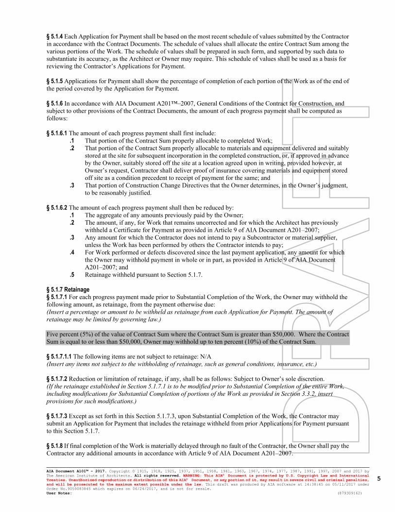
§ 5.1.7 Retainage§ 5.1.7.1 For each progress payment made prior to Substantial Completion of the Work, the Owner may withhold the following amount, as retainage, from the payment otherwise due:(Insert a percentage or amount to be withheld as retainage from each Application for Payment. The amount of retainage may be limited by governing law.)
Five percent (5%) of the value of Contract Sum where the Contract Sum is greater than $50,000. Where the Contract Sum is equal to or less than $50,000, Owner may withhold up to ten percent (10%) of the Contract Sum.
§ 5.1.7.1.1 The following items are not subject to retainage: N/A(Insert any items not subject to the withholding of retainage, such as general conditions, insurance, etc.)
§ 5.1.7.2 Reduction or limitation of retainage, if any, shall be as follows: Subject to Owner’s sole discretion.(If the retainage established in Section 5.1.7.1 is to be modified prior to Substantial Completion of the entire Work, including modifications for Substantial Completion of portions of the Work as provided in Section 3.3.2, insert provisions for such modifications.)
§ 5.1.7.3 Except as set forth in this Section 5.1.7.3, upon Substantial Completion of the Work, the Contractor may submit an Application for Payment that includes the retainage withheld from prior Applications for Payment pursuant to this Section 5.1.7.
§ 5.1.8 If final completion of the Work is materially delayed through no fault of the Contractor, the Owner shall pay the Contractor any additional amounts in accordance with Article 9 of AIA Document A201–2007.

AIA Document A101™ – 2017. Copyright © 1915, 1918, 1925, 1937, 1951, 1958, 1961, 1963, 1967, 1974, 1977, 1987, 1991, 1997, 2007 and 2017 by The American Institute of Architects. All rights reserved. WARNING: This AIA® Document is protected by U.S. Copyright Law and International Treaties. Unauthorized reproduction or distribution of this AIA® Document, or any portion of it, may result in severe civil and criminal penalties, and will be prosecuted to the maximum extent possible under the law. This draft was produced by AIA software at 14:38:45 on 05/11/2017 under Order No.9059083845 which expires on 06/24/2017, and is not for resale.User Notes: (879309162)
6
§ 5.1.9 Except with the Owner’s prior approval, the Contractor shall not make advance payments to suppliers for materials or equipment which have not been delivered and stored at the site.
§ 5.2 Final Payment§ 5.2.1 Final payment, constituting the entire unpaid balance of the Contract Sum, shall be made by the Owner to the Contractor when
.1 the Contractor has fully performed the Contract except for the Contractor’s responsibility to correct Work as provided in Article 12 of AIA Document A201–2007, and to satisfy other requirements, if any, which extend beyond final payment; and
.2 if required by the Owner, a final Certificate for Payment has been issued by the Architect and approved by the Owner;
.3 final lien waivers have been provided by the Contractor and all Subcontractors and material suppliers, conditioned only upon receipt of payments to be made out of the final Payment;
.4 a set of final as-built drawings for the Project have been provided to the Owner; and
.5 all other requirements in Section 9.10 of AIA Document A201-2007 have been satisfied.
§ 5.2.2 The Owner’s final payment to the Contractor shall be made no later than thirty (30) days after all requirements of Section 5.2.1 have been satisfied.
§ 5.3 InterestPayments due and unpaid under the Contract except for disputed amounts shall bear interest from the date payment is due at the rate stated below, or in the absence thereof, at the legal rate prevailing from time to time at the place where the Project is located.(Insert rate of interest agreed upon, if any.)
Prime Rate, as announced in The Wall Street Journal, plus 1%.
ARTICLE 6 DISPUTE RESOLUTION§ 6.1 Initial Decision Maker
§ 6.2 Binding Dispute ResolutionAll claims, disputes and other matters in question arising out of, or relating to, this Agreement or the breach thereof shall be decided by the Zoological Commission of the Owner. The Zoological Commission shall afford both the Owner and the Contractor a reasonable opportunity to be heard and to offer evidence in support of their respective positions. In the absence of fraud or bad faith, the decision of the Zoological Commission shall be final and binding upon the parties and the parties shall abide by such decision. However, any such decision shall be subject to review or appeal by an appropriate court as provided below. Any review or appeal of the decision of the Zoological Commission or any claim by either party for a restraining order, injunction or other form of equitable relief shall be decided by litigation in any court of competent jurisdiction located in the City of St. Louis, Missouri. No claim, dispute or other matter in question between the parties to this Agreement, arising out of this Agreement or the breach thereof, shall be submitted to arbitration. The prevailing party in any litigation shall be reimbursed its reasonable attorney’s fees and costs by the non-prevailing party. The trier of fact shall as part of its judgment determine the prevailing party.If the Owner and Contractor do not select a method of binding dispute resolution, or do not subsequently agree in writing to a binding dispute resolution method other than litigation, Claims will be resolved by litigation in a court of competent jurisdiction.
ARTICLE 7 TERMINATION OR SUSPENSION§ 7.1 The Contract may be terminated by the Owner or the Contractor as provided in Article 14 of AIA Document A201–2007.
§ 7.1.1 If the Contract is terminated for the Owner’s convenience in accordance with Article 14 of AIA Document A201–2007, then no termination fee shall apply, however, the Owner shall pay the Contractor in accordance with Article 14 of the AIA Document A201-2007(Insert the amount of, or method for determining, the fee, if any, payable to the Contractor following a termination for the Owner’s convenience.)
§ 7.2 The Work may be suspended by the Owner as provided in Article 14 of AIA Document A201–2007.
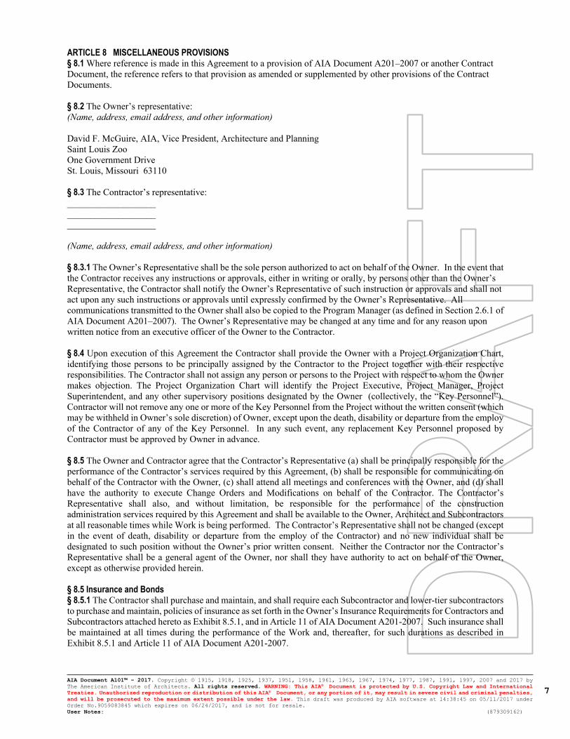
AIA Document A101™ – 2017. Copyright © 1915, 1918, 1925, 1937, 1951, 1958, 1961, 1963, 1967, 1974, 1977, 1987, 1991, 1997, 2007 and 2017 by The American Institute of Architects. All rights reserved. WARNING: This AIA® Document is protected by U.S. Copyright Law and International Treaties. Unauthorized reproduction or distribution of this AIA® Document, or any portion of it, may result in severe civil and criminal penalties, and will be prosecuted to the maximum extent possible under the law. This draft was produced by AIA software at 14:38:45 on 05/11/2017 under Order No.9059083845 which expires on 06/24/2017, and is not for resale.User Notes: (879309162)
7
ARTICLE 8 MISCELLANEOUS PROVISIONS§ 8.1 Where reference is made in this Agreement to a provision of AIA Document A201–2007 or another Contract Document, the reference refers to that provision as amended or supplemented by other provisions of the Contract Documents.
§ 8.2 The Owner’s representative:(Name, address, email address, and other information)
David F. McGuire, AIA, Vice President, Architecture and PlanningSaint Louis ZooOne Government DriveSt. Louis, Missouri 63110
§ 8.3 The Contractor’s representative:_________________________________________________________
(Name, address, email address, and other information)
§ 8.3.1 The Owner’s Representative shall be the sole person authorized to act on behalf of the Owner. In the event that the Contractor receives any instructions or approvals, either in writing or orally, by persons other than the Owner’s Representative, the Contractor shall notify the Owner’s Representative of such instruction or approvals and shall not act upon any such instructions or approvals until expressly confirmed by the Owner’s Representative. All communications transmitted to the Owner shall also be copied to the Program Manager (as defined in Section 2.6.1 of AIA Document A201–2007). The Owner’s Representative may be changed at any time and for any reason upon written notice from an executive officer of the Owner to the Contractor.
§ 8.4 Upon execution of this Agreement the Contractor shall provide the Owner with a Project Organization Chart, identifying those persons to be principally assigned by the Contractor to the Project together with their respective responsibilities. The Contractor shall not assign any person or persons to the Project with respect to whom the Owner makes objection. The Project Organization Chart will identify the Project Executive, Project Manager, Project Superintendent, and any other supervisory positions designated by the Owner (collectively, the “Key Personnel”). Contractor will not remove any one or more of the Key Personnel from the Project without the written consent (which may be withheld in Owner’s sole discretion) of Owner, except upon the death, disability or departure from the employ of the Contractor of any of the Key Personnel. In any such event, any replacement Key Personnel proposed by Contractor must be approved by Owner in advance.
§ 8.5 The Owner and Contractor agree that the Contractor’s Representative (a) shall be principally responsible for the performance of the Contractor’s services required by this Agreement, (b) shall be responsible for communicating on behalf of the Contractor with the Owner, (c) shall attend all meetings and conferences with the Owner, and (d) shall have the authority to execute Change Orders and Modifications on behalf of the Contractor. The Contractor’s Representative shall also, and without limitation, be responsible for the performance of the construction administration services required by this Agreement and shall be available to the Owner, Architect and Subcontractors at all reasonable times while Work is being performed. The Contractor’s Representative shall not be changed (except in the event of death, disability or departure from the employ of the Contractor) and no new individual shall be designated to such position without the Owner’s prior written consent. Neither the Contractor nor the Contractor’s Representative shall be a general agent of the Owner, nor shall they have authority to act on behalf of the Owner, except as otherwise provided herein.
§ 8.5 Insurance and Bonds§ 8.5.1 The Contractor shall purchase and maintain, and shall require each Subcontractor and lower-tier subcontractors to purchase and maintain, policies of insurance as set forth in the Owner’s Insurance Requirements for Contractors and Subcontractors attached hereto as Exhibit 8.5.1, and in Article 11 of AIA Document A201-2007. Such insurance shall be maintained at all times during the performance of the Work and, thereafter, for such durations as described in Exhibit 8.5.1 and Article 11 of AIA Document A201-2007.

AIA Document A101™ – 2017. Copyright © 1915, 1918, 1925, 1937, 1951, 1958, 1961, 1963, 1967, 1974, 1977, 1987, 1991, 1997, 2007 and 2017 by The American Institute of Architects. All rights reserved. WARNING: This AIA® Document is protected by U.S. Copyright Law and International Treaties. Unauthorized reproduction or distribution of this AIA® Document, or any portion of it, may result in severe civil and criminal penalties, and will be prosecuted to the maximum extent possible under the law. This draft was produced by AIA software at 14:38:45 on 05/11/2017 under Order No.9059083845 which expires on 06/24/2017, and is not for resale.User Notes: (879309162)
8
§ 8.5.2 The Contractor shall provide payment and performance bonds in the full amount of the Contract Sum and as otherwise required in the Contract Documents.
§ 8.6 [Intentionally omitted]
§ 8.7 Other provisions:
§ 8.7.1 The Contractor acknowledges that this Project is sensitive to various public interests as this Project has long-term effects on the St. Louis Zoo and Forest Park. The Contractor shall maintain the confidentiality of information specifically designated as confidential by the Owner (“Confidential Information”) and shall not disclose any Confidential Information to any third party or any employees of the Contractor except for those employees who have a need to know such information, without the Owner’s prior written consent in each instance, unless withholding such information would violate the law, create the risk of significant harm to the public or prevent the Contractor from establishing a claim or defense in an adjudicatory proceeding. Confidential Information disclosed to the Contractor remains the property of the Owner. All Confidential Information and any copies shall be promptly returned to the Owner (or destroyed if acceptable to Owner) upon completion of the Work or upon Owner’s written request. Contractor shall provide written certification of compliance with this Section within thirty (30) days after the request of Owner. Notwithstanding any limitation herein to the contrary, Owner shall be entitled to all remedies at law or in equity for any breach or threatened breach by Contractor of its duty to keep confidential any Confidential Information it obtains from Owner. The Contractor shall require each of the Contractor’s subcontractors to execute and deliver similar agreements to maintain the confidentiality of information defined as Confidential Information above. In addition, all public relations matters arising out of or in connection with the Project shall be the responsibility of and handled by the Owner. The Contractor shall not make any public announcement or publication, or post Project signs in connection with the Project without the Owner’s prior written approval in each instance, which approval shall not be unreasonably withheld.
§ 8.7.2 Without limiting the generality of any other provision of this Agreement, Contractor shall comply with, and shall cause its Subcontractors to comply with, all statutes, ordinances, codes, rules and regulations, and lawful orders of public authorities relating to employment of unauthorized aliens, including, without limitation, R.S.Mo. §§ 285.525 – 285.550, if applicable, the Federal Employment Eligibility Verification Program (E-Verify) (Title IV, Subtitle A, of the Illegal Immigration Reform and Immigrant Responsibility Act of 1996 (IIRIRA), Pub. L. 104-208, 110 Stat. 3009, as amended (8 U.S.C. § 1324a note)) and all requirements of the Owner’s Project Manual attached hereto as Exhibit 8.7.2(a), including without limitation, those Appendices attached thereto and incorporated herein by reference. Contractor represents and warrants to Owner that Contractor is not knowingly in violation of subsection 1 of R.S.Mo. § 285.530 and shall not henceforth be in such violation. Contractor has provided Owner with a sworn affidavit as prescribed by 15 CSR § 60-15.020, which affidavit is attached to this Contract as Exhibit 8.7.2(b).
§ 8.7.3 All notices must be in writing. Notices and Owner’s payments may be made by either (a) depositing the same in the United States mail addressed to the party to be notified (or paid, as applicable), postpaid and registered or certified with return receipt requested or (b) personal delivery. Notice mailed in accordance with this Section will be effective, unless otherwise stated in the notice or in this Agreement, three (3) days after the date postmarked on the envelope containing the notice. Notice given by personal delivery will be effective when received. All notices to Contractor and Owner must be mailed to or personally delivered to the following addresses:
If to the Contractor: ___________________ ________________________________________
If to the Owner: St. Louis ZooOne Government DriveSt. Louis, MO 63110Attn: David F. McGuire, AIA, Vice President, Architecture and Planning
By giving the other party at least ten (10) days written notice, either party may change its address to any other address in the United States of America.
§ 8.7.4 The Contractor represents that it has visited the site and is fully familiar with the existing operations at, adjacent to, or in reasonable proximity to the Project. The Contractor acknowledges that employees, agents, invitees, licensees
AIA Document A101™ – 2017. Copyright © 1915, 1918, 1925, 1937, 1951, 1958, 1961, 1963, 1967, 1974, 1977, 1987, 1991, 1997, 2007 and 2017 by The American Institute of Architects. All rights reserved. WARNING: This AIA® Document is protected by U.S. Copyright Law and International Treaties. Unauthorized reproduction or distribution of this AIA® Document, or any portion of it, may result in severe civil and criminal penalties, and will be prosecuted to the maximum extent possible under the law. This draft was produced by AIA software at 14:38:45 on 05/11/2017 under Order No.9059083845 which expires on 06/24/2017, and is not for resale.User Notes: (879309162)
9
and others of Owner and Owner’s affiliates occupy and conduct operations at or adjacent to the Project location. The Contractor represents that, based on the foregoing, Contractor has made its own evaluation and analysis of the necessary safety precautions needed to maintain continuing operation of the existing zoo facilities in accordance with the requirements of the Contract Documents. The Contractor and its Subcontractors of all tiers, material and equipment suppliers and manufacturers, and agents and employees of any of them shall, (a) cause no damage to the existing facilities or the operations and activities therein through any means, including but not limited to, noise, vibration, or dust created in the performance of Work; (b) cause no interruptions to the operations and activities in the existing facilities; and (c) use its best efforts to cause no interruptions in utility or other services to the existing facilities or the operations and activities therein, except as may be indicated in the Contract Documents or pre-approved in writing by the Owner. Contractor shall safeguard and protect Owner and Owner’s employees, agents, invitees and licensees from injury or damage caused by the Work. The Contractor shall cause its Subcontractors of all tiers, material and equipment suppliers and manufacturers, and agents and employees of any of them to only use entrances, access points, elevators, staging and parking areas as designated and approved by the Owner. The Contractor assumes responsibility for, and all risk in connection with, the Work and the risk of any loss arising out of any breach of this Section 8.7.4.
ARTICLE 9 ENUMERATION OF CONTRACT DOCUMENTS§ 9.1 This Agreement is comprised of the following documents:
.1 AIA Document A101™–2017, Standard Form of Agreement Between Owner and Contractor
.2 Reserved
.3 AIA Document A201™–2007, General Conditions of the Contract for Construction
.4 Reserved
.5 Drawings: See Exhibit 9.1.5
.6 Specifications: See Exhibit 9.1.6
.7 Addenda, if any: See Exhibit 9.1.7
Portions of Addenda relating to bidding or proposal requirements are not part of the Contract Documents unless the bidding or proposal requirements are also enumerated in this Article 9.
.8 Other Exhibits:(Check all boxes that apply and include appropriate information identifying the exhibit where required.)
[ « » ] AIA Document E204™–2017, Sustainable Projects Exhibit, dated as indicated below:(Insert the date of the E204-2017 incorporated into this Agreement.)
[ « » ] The Sustainability Plan:
[ « » ] Supplementary and other Conditions of the Contract:
.9 Other documents, if any, listed below:(List here any additional documents that are intended to form part of the Contract Documents. AIA Document A201™–2007 provides that the advertisement or invitation to bid, Instructions to Bidders, sample forms, the Contractor’s bid or proposal, portions of Addenda relating to bidding or proposal requirements, and other information furnished by the Owner in anticipation of receiving bids or proposals, are not part of the Contract Documents unless enumerated in this Agreement. Any such documents should be listed here only if intended to be part of the Contract Documents.)
List of Attachments:
Exhibit 3.3.2; Construction Schedule (see Section 3.3.2)Exhibit 8.7.2(a): Owner’s Project ManualExhibit 8.7.2(b): Affidavit Regarding Employment of Unauthorized Aliens
(per 15 CSR § 60-15.020)Exhibit 9.1.5; List of Drawings (see Section 9.1.5)Exhibit 9.1.6; Specifications (see Section 9.1.6)Exhibit 9.1.7; Addenda (see Section 9.1.7)Exhibit 8.5.1; Insurance Requirements for Contractors and Subcontractors (see Section 8.5.1)

AIA Document A101™ – 2017. Copyright © 1915, 1918, 1925, 1937, 1951, 1958, 1961, 1963, 1967, 1974, 1977, 1987, 1991, 1997, 2007 and 2017 by The American Institute of Architects. All rights reserved. WARNING: This AIA® Document is protected by U.S. Copyright Law and International Treaties. Unauthorized reproduction or distribution of this AIA® Document, or any portion of it, may result in severe civil and criminal penalties, and will be prosecuted to the maximum extent possible under the law. This draft was produced by AIA software at 14:38:45 on 05/11/2017 under Order No.9059083845 which expires on 06/24/2017, and is not for resale.User Notes: (879309162)
10
AIA Document A101™ – 2017. Copyright © 1915, 1918, 1925, 1937, 1951, 1958, 1961, 1963, 1967, 1974, 1977, 1987, 1991, 1997, 2007 and 2017 by The American Institute of Architects. All rights reserved. WARNING: This AIA® Document is protected by U.S. Copyright Law and International Treaties. Unauthorized reproduction or distribution of this AIA® Document, or any portion of it, may result in severe civil and criminal penalties, and will be prosecuted to the maximum extent possible under the law. This draft was produced by AIA software at 14:38:45 on 05/11/2017 under Order No.9059083845 which expires on 06/24/2017, and is not for resale.User Notes: (879309162)
11
This Agreement entered into as of the day and year first written above.
ZOOLOGICAL SUBDISTRICT OF THE METROPOLITAN ZOOLOGICAL PARK AND MUSEUM DISTRICT
OWNER (Signature) CONTRACTOR (Signature)
Winthrop B. Reed, III, Chairman of the Saint Louis Zoological Park Subdistrict Commission(Printed name and title) (Printed name and title)

AIA Document A101™ – 2017. Copyright © 1915, 1918, 1925, 1937, 1951, 1958, 1961, 1963, 1967, 1974, 1977, 1987, 1991, 1997, 2007 and 2017 by The American Institute of Architects. All rights reserved. WARNING: This AIA® Document is protected by U.S. Copyright Law and International Treaties. Unauthorized reproduction or distribution of this AIA® Document, or any portion of it, may result in severe civil and criminal penalties, and will be prosecuted to the maximum extent possible under the law. This draft was produced by AIA software at 14:38:45 on 05/11/2017 under Order No.9059083845 which expires on 06/24/2017, and is not for resale.User Notes: (879309162)
12
EXHIBIT 3.3.2CONSTRUCTION SCHEDULE

AIA Document A101™ – 2017. Copyright © 1915, 1918, 1925, 1937, 1951, 1958, 1961, 1963, 1967, 1974, 1977, 1987, 1991, 1997, 2007 and 2017 by The American Institute of Architects. All rights reserved. WARNING: This AIA® Document is protected by U.S. Copyright Law and International Treaties. Unauthorized reproduction or distribution of this AIA® Document, or any portion of it, may result in severe civil and criminal penalties, and will be prosecuted to the maximum extent possible under the law. This draft was produced by AIA software at 14:38:45 on 05/11/2017 under Order No.9059083845 which expires on 06/24/2017, and is not for resale.User Notes: (879309162)
13
EXHIBIT 8.7.2(A)OWNER’S PROJECT MANUAL
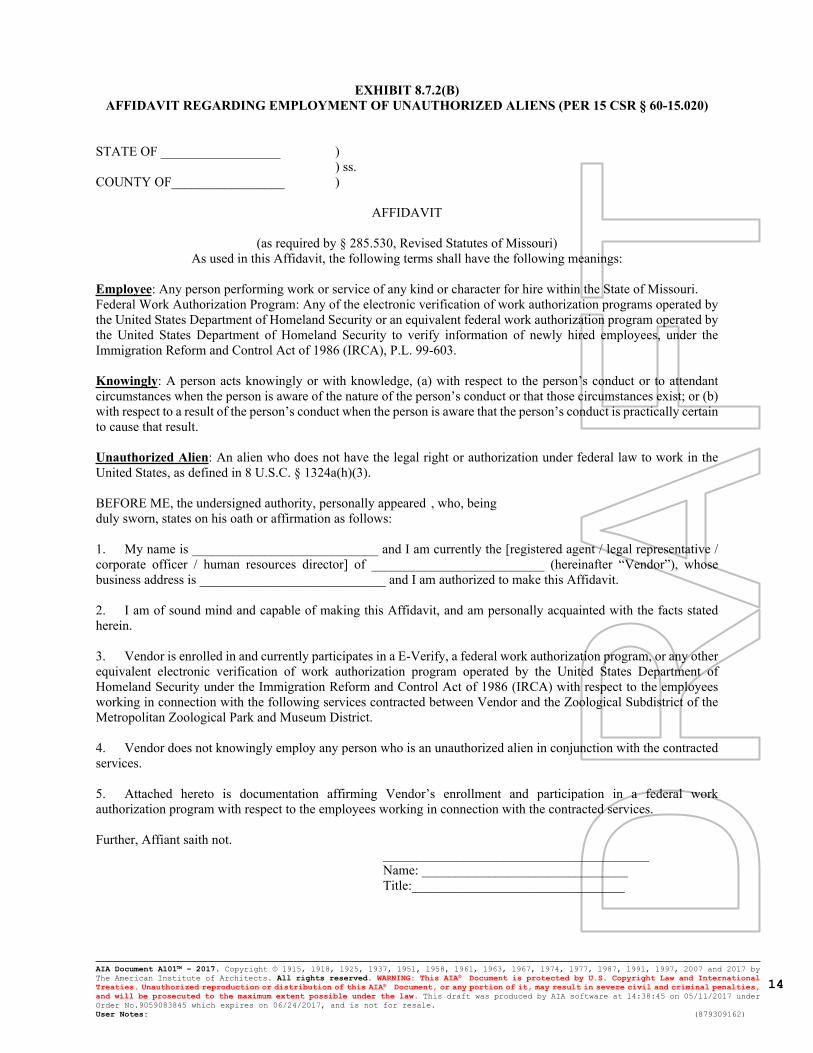
AIA Document A101™ – 2017. Copyright © 1915, 1918, 1925, 1937, 1951, 1958, 1961, 1963, 1967, 1974, 1977, 1987, 1991, 1997, 2007 and 2017 by The American Institute of Architects. All rights reserved. WARNING: This AIA® Document is protected by U.S. Copyright Law and International Treaties. Unauthorized reproduction or distribution of this AIA® Document, or any portion of it, may result in severe civil and criminal penalties, and will be prosecuted to the maximum extent possible under the law. This draft was produced by AIA software at 14:38:45 on 05/11/2017 under Order No.9059083845 which expires on 06/24/2017, and is not for resale.User Notes: (879309162)
14
EXHIBIT 8.7.2(B)AFFIDAVIT REGARDING EMPLOYMENT OF UNAUTHORIZED ALIENS (PER 15 CSR § 60-15.020)
STATE OF __________________ )
) ss.COUNTY OF_________________ )
AFFIDAVIT
(as required by § 285.530, Revised Statutes of Missouri)As used in this Affidavit, the following terms shall have the following meanings:
Employee: Any person performing work or service of any kind or character for hire within the State of Missouri.Federal Work Authorization Program: Any of the electronic verification of work authorization programs operated by the United States Department of Homeland Security or an equivalent federal work authorization program operated by the United States Department of Homeland Security to verify information of newly hired employees, under the Immigration Reform and Control Act of 1986 (IRCA), P.L. 99-603.
Knowingly: A person acts knowingly or with knowledge, (a) with respect to the person’s conduct or to attendant circumstances when the person is aware of the nature of the person’s conduct or that those circumstances exist; or (b) with respect to a result of the person’s conduct when the person is aware that the person’s conduct is practically certain to cause that result.
Unauthorized Alien: An alien who does not have the legal right or authorization under federal law to work in the United States, as defined in 8 U.S.C. § 1324a(h)(3).
BEFORE ME, the undersigned authority, personally appeared , who, beingduly sworn, states on his oath or affirmation as follows:
1. My name is ____________________________ and I am currently the [registered agent / legal representative / corporate officer / human resources director] of __________________________ (hereinafter “Vendor”), whose business address is ____________________________ and I am authorized to make this Affidavit.
2. I am of sound mind and capable of making this Affidavit, and am personally acquainted with the facts stated herein.
3. Vendor is enrolled in and currently participates in a E-Verify, a federal work authorization program, or any other equivalent electronic verification of work authorization program operated by the United States Department of Homeland Security under the Immigration Reform and Control Act of 1986 (IRCA) with respect to the employees working in connection with the following services contracted between Vendor and the Zoological Subdistrict of the Metropolitan Zoological Park and Museum District.
4. Vendor does not knowingly employ any person who is an unauthorized alien in conjunction with the contracted services.
5. Attached hereto is documentation affirming Vendor’s enrollment and participation in a federal work authorization program with respect to the employees working in connection with the contracted services.
Further, Affiant saith not.________________________________________Name: _______________________________Title:________________________________

AIA Document A101™ – 2017. Copyright © 1915, 1918, 1925, 1937, 1951, 1958, 1961, 1963, 1967, 1974, 1977, 1987, 1991, 1997, 2007 and 2017 by The American Institute of Architects. All rights reserved. WARNING: This AIA® Document is protected by U.S. Copyright Law and International Treaties. Unauthorized reproduction or distribution of this AIA® Document, or any portion of it, may result in severe civil and criminal penalties, and will be prosecuted to the maximum extent possible under the law. This draft was produced by AIA software at 14:38:45 on 05/11/2017 under Order No.9059083845 which expires on 06/24/2017, and is not for resale.User Notes: (879309162)
15
EXHIBIT 9.1.5LIST OF DRAWINGS

AIA Document A101™ – 2017. Copyright © 1915, 1918, 1925, 1937, 1951, 1958, 1961, 1963, 1967, 1974, 1977, 1987, 1991, 1997, 2007 and 2017 by The American Institute of Architects. All rights reserved. WARNING: This AIA® Document is protected by U.S. Copyright Law and International Treaties. Unauthorized reproduction or distribution of this AIA® Document, or any portion of it, may result in severe civil and criminal penalties, and will be prosecuted to the maximum extent possible under the law. This draft was produced by AIA software at 14:38:45 on 05/11/2017 under Order No.9059083845 which expires on 06/24/2017, and is not for resale.User Notes: (879309162)
16
EXHIBIT 9.1.6SPECIFICATIONS

AIA Document A101™ – 2017. Copyright © 1915, 1918, 1925, 1937, 1951, 1958, 1961, 1963, 1967, 1974, 1977, 1987, 1991, 1997, 2007 and 2017 by The American Institute of Architects. All rights reserved. WARNING: This AIA® Document is protected by U.S. Copyright Law and International Treaties. Unauthorized reproduction or distribution of this AIA® Document, or any portion of it, may result in severe civil and criminal penalties, and will be prosecuted to the maximum extent possible under the law. This draft was produced by AIA software at 14:38:45 on 05/11/2017 under Order No.9059083845 which expires on 06/24/2017, and is not for resale.User Notes: (879309162)
17
EXHIBIT 9.1.7ADDENDA

AIA Document A101™ – 2017. Copyright © 1915, 1918, 1925, 1937, 1951, 1958, 1961, 1963, 1967, 1974, 1977, 1987, 1991, 1997, 2007 and 2017 by The American Institute of Architects. All rights reserved. WARNING: This AIA® Document is protected by U.S. Copyright Law and International Treaties. Unauthorized reproduction or distribution of this AIA® Document, or any portion of it, may result in severe civil and criminal penalties, and will be prosecuted to the maximum extent possible under the law. This draft was produced by AIA software at 14:38:45 on 05/11/2017 under Order No.9059083845 which expires on 06/24/2017, and is not for resale.User Notes: (879309162)
18
EXHIBIT 8.5.1INSURANCE REQUIREMENTS FOR CONTRACTORS AND SUBCONTRACTORS
1. Contractor and all subcontractors (collectively “Contractors”) shall, unless otherwise approved in writing by Owner, obtain and maintain throughout the duration of the Project (or as otherwise specified) insurance of the types and in the amounts described below (the “Required Insurance”):
1.1 Commercial General Liability Insurance.
1.1.1 Combined single limit of:
$1,000,000 Each Occurrence$2,000,000 General Aggregate$2,000,000 Products/Completed Operations Aggregate$1,000,000 Personal and Advertising Injury
1.1.2 Coverage Required: Per project aggregate, premises-operations, explosion, collapse, underground, products/completed operations, independent contractors, blanket contractual liability, personal injury liability, general liability primary (non-contributory), additional insured (CG 20 10 11/85 or its equivalent) including products/completed operations coverage and waiver of subrogation, Designated Construction Project(s) General Aggregate Limit endorsement (CG 25 03 03 97 or its equivalent), and Designated Location(s) General Aggregate Limit endorsement (CG 25 04 03 97 or its equivalent). Insurance is to be on an occurrence form insuring bodily injury and property damage against the hazards of: construction operations, subcontractors and independent contractors, and shall include an aggregate limit per job site endorsement. Products and completed operation insurance shall remain in force five (5) years following completion of project.
Owner shall be included as an insured under the commercial general liability insurance, using Additional Insured Endorsement (CG 20 10 11/85 or its equivalent).
1.2 Business Auto Liability Insurance.
1.2.1 Combined Single Limit of:
$1,000,000 each Occurrence Bodily Injury and Property Damage
1.2.2 Coverage Required: Primary for all owned automobiles; including liability for all owned hired/non-owned automobiles leased, rented and/or borrowed cars/trucks; medical payments, uninsured and underinsured motorists coverage.
Owner shall be included as additional insured. An MCS-90 endorsement (or its equivalent) shall be attached when operations require this coverage.
1.3 Workers’ Compensation Insurance.
1.3.1 Workers’ Compensation Limits: Statutory
1.3.2 Employers’ Liability Limits:
Bodily Injury by Accident $1,000,000 Each AccidentBodily Injury by Disease $1,000,000 Policy LimitBodily Injury by Disease $1,000,000 Each Employee
1.3.3 Workers compensation limits shall not be less than the law requires.
1.4 Excess Umbrella Insurance.
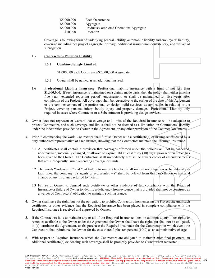
AIA Document A101™ – 2017. Copyright © 1915, 1918, 1925, 1937, 1951, 1958, 1961, 1963, 1967, 1974, 1977, 1987, 1991, 1997, 2007 and 2017 by The American Institute of Architects. All rights reserved. WARNING: This AIA® Document is protected by U.S. Copyright Law and International Treaties. Unauthorized reproduction or distribution of this AIA® Document, or any portion of it, may result in severe civil and criminal penalties, and will be prosecuted to the maximum extent possible under the law. This draft was produced by AIA software at 14:38:45 on 05/11/2017 under Order No.9059083845 which expires on 06/24/2017, and is not for resale.User Notes: (879309162)
19
$5,000,000 Each Occurrence$5,000,000 Aggregate$5,000,000 Products/Completed Operations Aggregate
$10,000 Retention
Coverage is following form of underlying general liability, automobile liability and employers’ liability, coverage including per project aggregate, primary, additional insured/non-contributory, and waiver of subrogation.
1.5 Contractor’s Pollution Liability.
1.5.1 Combined Single Limit of:
$1,000,000 each Occurrence/$2,000,000 Aggregate
1.5.2 Owner shall be named as an additional insured.
1.6 Professional Liability Insurance Professional liability insurance with a limit of not less than $1,000,000. If such insurance is maintained on a claims-made basis, then the policy shall either attach a five year “extended reporting period” endorsement, or shall be maintained for five years after completion of the Project. All coverages shall be retroactive to the earlier of the date of this Agreement or the commencement of the professional or design-build services, as applicable, in relation to the Project, covering personal injury, bodily injury and property damage. Professional Liability only required in cases where Contractor or a Subcontractor is providing design services.
2. Owner does not represent or warrant that coverage and limits of the Required Insurance will be adequate to protect Contractors, and such coverage and limits shall not be deemed as a limitation on Contractors’ liability under the indemnities provided to Owner in the Agreement, or any other provision of the Contract Documents.
3. Prior to commencing the work, Contractors shall furnish Owner with a certificate(s) of insurance, executed by a duly authorized representative of each insurer, showing that the Contractors maintain the Required Insurance.
3.1 All certificates shall contain a provision that coverages afforded under the policies will not be cancelled, non-renewed, materially changed, or allowed to expire until at least thirty (30) days’ prior written notice has been given to the Owner. The Contractors shall immediately furnish the Owner copies of all endorsements that are subsequently issued amending coverage or limits.
3.2 The words “endeavor to” and “but failure to mail such notice shall impose no obligation or liability of any kind upon the company, its agents or representatives” shall be deleted from the cancellation or material change of any insurance referred to therein.
3.3 Failure of Owner to demand such certificate or other evidence of full compliance with the Required Insurance or failure of Owner to identify a deficiency from evidence that is provided shall not be construed as a waiver of Contractors’ obligation to maintain such insurance.
4. Owner shall have the right, but not the obligation, to prohibit Contractors from entering the Project site until such certificates or other evidence that the Required Insurance has been placed in complete compliance with the Required Insurance is received and approved by Owner.
5. If the Contractors fails to maintain any or all of the Required Insurance, then, in addition to any other rights or remedies available to the Owner under the Agreement, the Owner shall have the right, but shall not be obligated, to (a) terminate the Agreement, or (b) purchase the Required Insurance for the Contractors in which event the Contractors shall reimburse the Owner for the cost thereof, plus ten percent (10%) as an administrative charge.
6. With respect to Required Insurance which the Contractors are obligated to maintain after final payment, an additional certificate(s) evidencing such coverage shall be promptly provided to Owner when requested.

AIA Document A101™ – 2017. Copyright © 1915, 1918, 1925, 1937, 1951, 1958, 1961, 1963, 1967, 1974, 1977, 1987, 1991, 1997, 2007 and 2017 by The American Institute of Architects. All rights reserved. WARNING: This AIA® Document is protected by U.S. Copyright Law and International Treaties. Unauthorized reproduction or distribution of this AIA® Document, or any portion of it, may result in severe civil and criminal penalties, and will be prosecuted to the maximum extent possible under the law. This draft was produced by AIA software at 14:38:45 on 05/11/2017 under Order No.9059083845 which expires on 06/24/2017, and is not for resale.User Notes: (879309162)
20
8. Contractors shall include the above insurance requirements in all of their subcontracts, unless otherwise agreed to in writing by Owner. Each Contractor shall be responsible for collecting certificates of insurance and monitoring insurance coverage of its subcontractors and all sub-subcontractors to verify that the required coverage is maintained as required. All Contractors providing professional services shall be required to provide professional liability insurance with limits of coverage not less than required herein with respect to the Contractors. In addition, all subcontractors shall include a similar indemnification of Owner as provided in the Agreement.
9. Contractors shall secure all Required Insurance from domestic insurer(s) authorized to do business in the State in which the Project is located and reasonably satisfactory to Owner with: (a) a claims paying ability of not less than “AA” (or the equivalent) by S&P and one other Rating Agency satisfactory to Owner; and (b) “A:X” or better financial strength rating by AM Best. Contractors shall obtain Owner’s reasonable approval of the form, substance, amounts, risk coverage, sublimits, deductibles, loss payees, and insureds for all Required Insurance. All coverages except Errors and Omissions shall be occurrence based. Required Insurance shall contain such provisions as Owner deems reasonably necessary or desirable to protect its interest. Contractors shall pay the premiums for all Required Insurance when due and payable.
St. Louis Zoo
Government DriveSt. Louis, MO
CHI-MO-04-20
Chiodini
Stingray Life Support Systems Building
04/16/2021
4/16/21

LOAD DEVELOPMENT
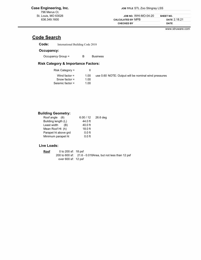
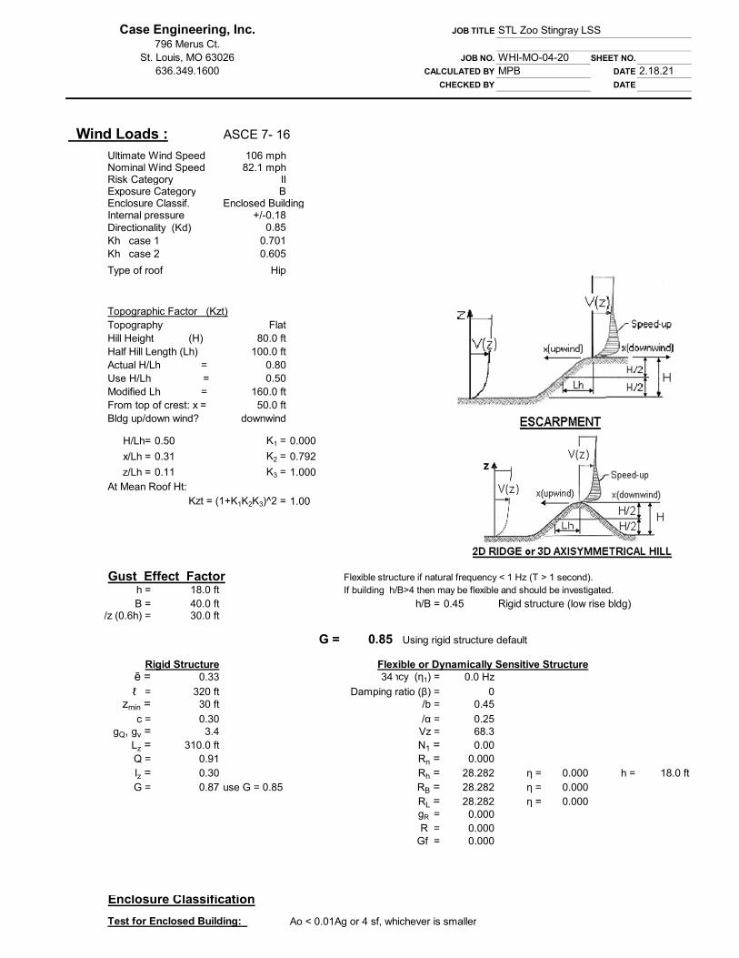
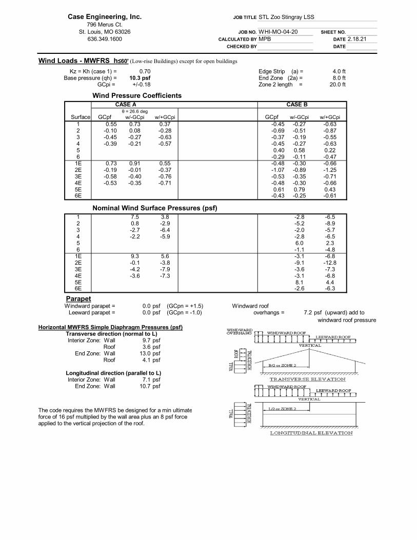
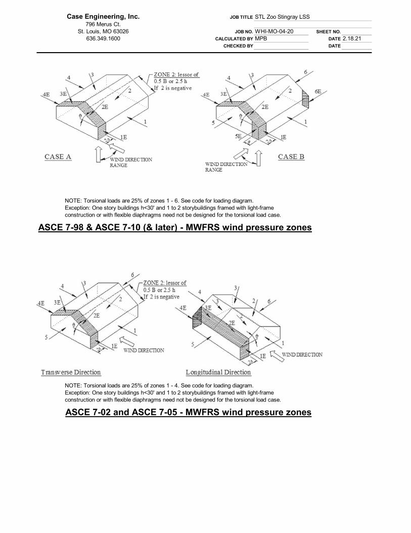
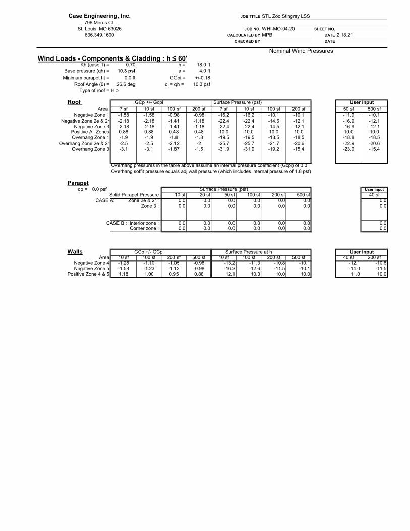

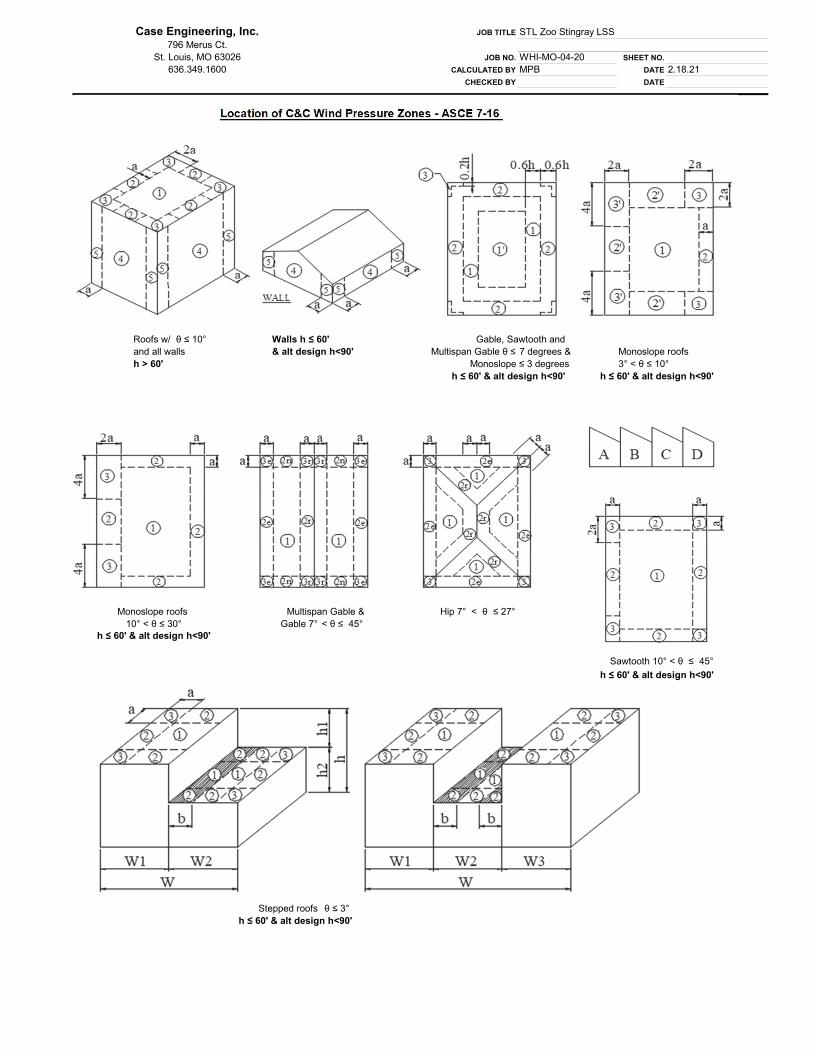

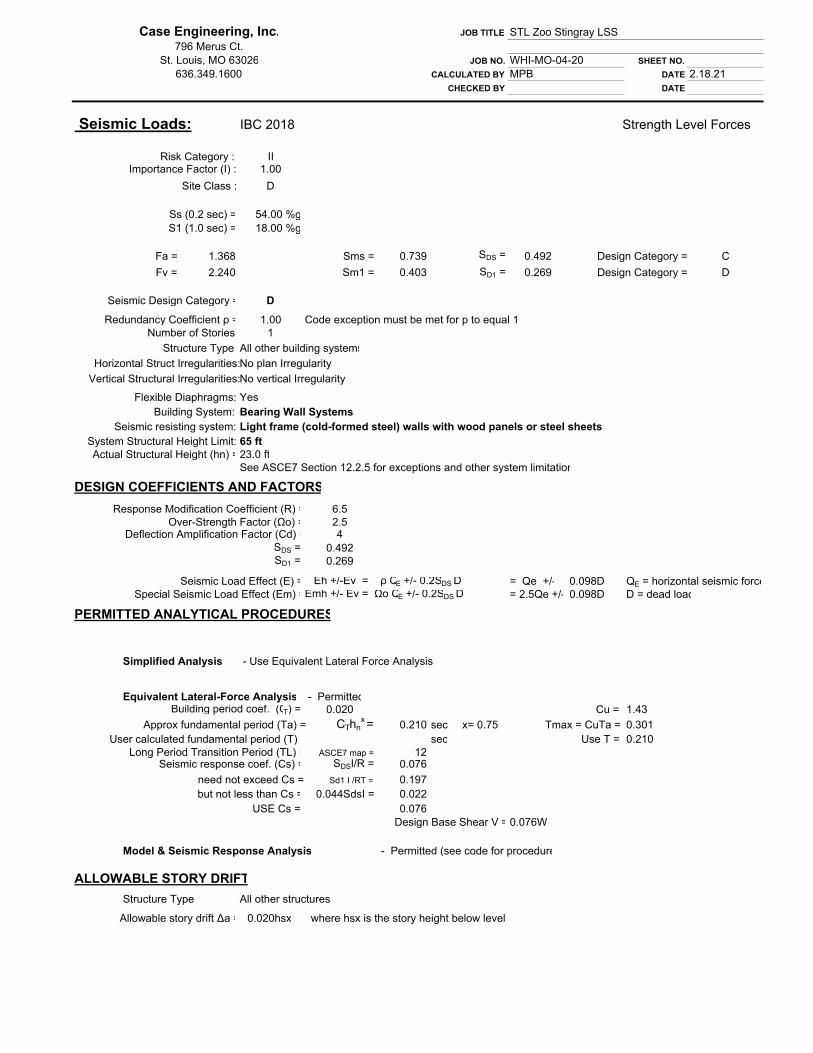

4/16/2021 ATC Hazards by Location
https://hazards.atcouncil.org/#/seismic?lat=38.6361519&lng=-90.2923103&address=Living World Building-St. Louis Zoo%2C Government Dr%2C St. … 1/2
Hazards by Location
Search Information
Address: Living World Building-St. Louis Zoo, Government Dr, St.Louis, MO 63110, USA
Coordinates: 38.6361519, -90.2923103
Elevation: 504 ft
Timestamp: 2021-04-16T19:18:42.063Z
Hazard Type: Seismic
ReferenceDocument:
ASCE7-16
Risk Category: II
Site Class: D-default
MCER Horizontal Response Spectrum Design Horizontal Response Spectrum
Basic Parameters
Name Value Description
SS 0.434 MCER ground motion (period=0.2s)
S1 0.157 MCER ground motion (period=1.0s)
SMS 0.63 Site-modified spectral acceleration value
SM1 0.359 Site-modified spectral acceleration value
SDS 0.42 Numeric seismic design value at 0.2s SA
SD1 0.239 Numeric seismic design value at 1.0s SA
Additional Information
Name Value Description
SDC D Seismic design category
Fa 1.453 Site amplification factor at 0.2s
Fv 2.286 Site amplification factor at 1.0s
504 ft504 ft
Map data ©2021 Google
0 2 4 6 8 10 12 Period (s)0.00
0.10
0.20
0.30
0.40
0.50
0.60
Sa(g)
0 2 4 6 8 10 12 Period (s)0.00
0.10
0.20
0.30
0.40
Sa(g)
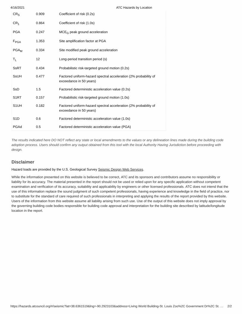
4/16/2021 ATC Hazards by Location
https://hazards.atcouncil.org/#/seismic?lat=38.6361519&lng=-90.2923103&address=Living World Building-St. Louis Zoo%2C Government Dr%2C St. … 2/2
CRS 0.909 Coefficient of risk (0.2s)
CR1 0.864 Coefficient of risk (1.0s)
PGA 0.247 MCEG peak ground acceleration
FPGA 1.353 Site amplification factor at PGA
PGAM 0.334 Site modified peak ground acceleration
TL 12 Long-period transition period (s)
SsRT 0.434 Probabilistic risk-targeted ground motion (0.2s)
SsUH 0.477 Factored uniform-hazard spectral acceleration (2% probability ofexceedance in 50 years)
SsD 1.5 Factored deterministic acceleration value (0.2s)
S1RT 0.157 Probabilistic risk-targeted ground motion (1.0s)
S1UH 0.182 Factored uniform-hazard spectral acceleration (2% probability ofexceedance in 50 years)
S1D 0.6 Factored deterministic acceleration value (1.0s)
PGAd 0.5 Factored deterministic acceleration value (PGA)
The results indicated here DO NOT reflect any state or local amendments to the values or any delineation lines made during the building codeadoption process. Users should confirm any output obtained from this tool with the local Authority Having Jurisdiction before proceeding withdesign.
DisclaimerHazard loads are provided by the U.S. Geological Survey Seismic Design Web Services.
While the information presented on this website is believed to be correct, ATC and its sponsors and contributors assume no responsibility orliability for its accuracy. The material presented in the report should not be used or relied upon for any specific application without competentexamination and verification of its accuracy, suitability and applicability by engineers or other licensed professionals. ATC does not intend that theuse of this information replace the sound judgment of such competent professionals, having experience and knowledge in the field of practice, norto substitute for the standard of care required of such professionals in interpreting and applying the results of the report provided by this website.Users of the information from this website assume all liability arising from such use. Use of the output of this website does not imply approval bythe governing building code bodies responsible for building code approval and interpretation for the building site described by latitude/longitudelocation in the report.
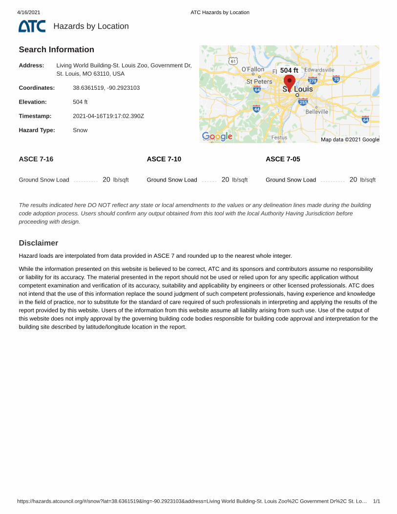
4/16/2021 ATC Hazards by Location
https://hazards.atcouncil.org/#/snow?lat=38.6361519&lng=-90.2923103&address=Living World Building-St. Louis Zoo%2C Government Dr%2C St. Lo… 1/1
Hazards by Location
Search Information
Address: Living World Building-St. Louis Zoo, Government Dr,St. Louis, MO 63110, USA
Coordinates: 38.6361519, -90.2923103
Elevation: 504 ft
Timestamp: 2021-04-16T19:17:02.390Z
Hazard Type: Snow
ASCE 7-16
Ground Snow Load 20 lb/sqft
ASCE 7-10
Ground Snow Load 20 lb/sqft
ASCE 7-05
Ground Snow Load 20 lb/sqft
The results indicated here DO NOT reflect any state or local amendments to the values or any delineation lines made during the buildingcode adoption process. Users should confirm any output obtained from this tool with the local Authority Having Jurisdiction beforeproceeding with design.
DisclaimerHazard loads are interpolated from data provided in ASCE 7 and rounded up to the nearest whole integer.
While the information presented on this website is believed to be correct, ATC and its sponsors and contributors assume no responsibilityor liability for its accuracy. The material presented in the report should not be used or relied upon for any specific application withoutcompetent examination and verification of its accuracy, suitability and applicability by engineers or other licensed professionals. ATC doesnot intend that the use of this information replace the sound judgment of such competent professionals, having experience and knowledgein the field of practice, nor to substitute for the standard of care required of such professionals in interpreting and applying the results of thereport provided by this website. Users of the information from this website assume all liability arising from such use. Use of the output ofthis website does not imply approval by the governing building code bodies responsible for building code approval and interpretation for thebuilding site described by latitude/longitude location in the report.
504 ft504 ft
Map data ©2021 Google

4/16/2021 ATC Hazards by Location
https://hazards.atcouncil.org/#/wind?lat=38.6361519&lng=-90.2923103&address=Living World Building-St. Louis Zoo%2C Government Dr%2C St. Lo… 1/2
Hazards by Location
Search Information
Address: Living World Building-St. Louis Zoo, Government Dr,St. Louis, MO 63110, USA
Coordinates: 38.6361519, -90.2923103
Elevation: 504 ft
Timestamp: 2021-04-16T19:15:02.348Z
Hazard Type: Wind
ASCE 7-16
MRI 10-Year 74 mph
MRI 25-Year 81 mph
MRI 50-Year 86 mph
MRI 100-Year 93 mph
Risk Category I 101 mph
Risk Category II 106 mph
Risk Category III 114 mph
Risk Category IV 118 mph
ASCE 7-10
MRI 10-Year 76 mph
MRI 25-Year 84 mph
MRI 50-Year 90 mph
MRI 100-Year 96 mph
Risk Category I 105 mph
Risk Category II 115 mph
Risk Category III-IV 120 mph
ASCE 7-05
ASCE 7-05 Wind Speed 90 mph
The results indicated here DO NOT reflect any state or local amendments to the values or any delineation lines made during the buildingcode adoption process. Users should confirm any output obtained from this tool with the local Authority Having Jurisdiction beforeproceeding with design.
DisclaimerHazard loads are interpolated from data provided in ASCE 7 and rounded up to the nearest whole integer. Per ASCE 7, islands and coastalareas outside the last contour should use the last wind speed contour of the coastal area – in some cases, this website will extrapolate pastthe last wind speed contour and therefore, provide a wind speed that is slightly higher. NOTE: For queries near wind-borne debris regionboundaries, the resulting determination is sensitive to rounding which may affect whether or not it is considered to be within a wind-bornedebris region.
Mountainous terrain, gorges, ocean promontories, and special wind regions shall be examined for unusual wind conditions.
While the information presented on this website is believed to be correct, ATC and its sponsors and contributors assume no responsibilityor liability for its accuracy. The material presented in the report should not be used or relied upon for any specific application withoutcompetent examination and verification of its accuracy, suitability and applicability by engineers or other licensed professionals. ATC doesnot intend that the use of this information replace the sound judgment of such competent professionals, having experience and knowledgein the field of practice, nor to substitute for the standard of care required of such professionals in interpreting and applying the results of thereport provided by this website. Users of the information from this website assume all liability arising from such use. Use of the output ofthis website does not imply approval by the governing building code bodies responsible for building code approval and interpretation for the
504 ft504 ft
Map data ©2021 Google

LATERAL LOAD ANALYSIS
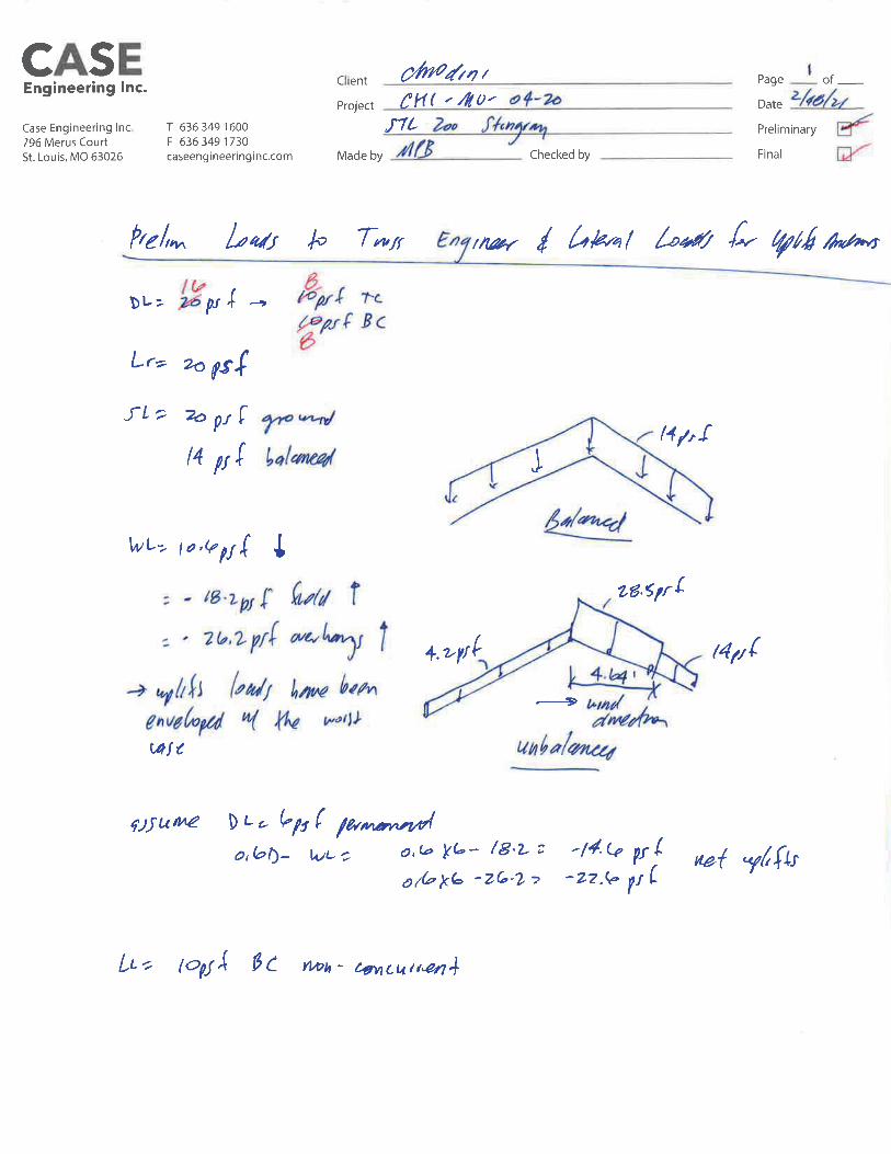
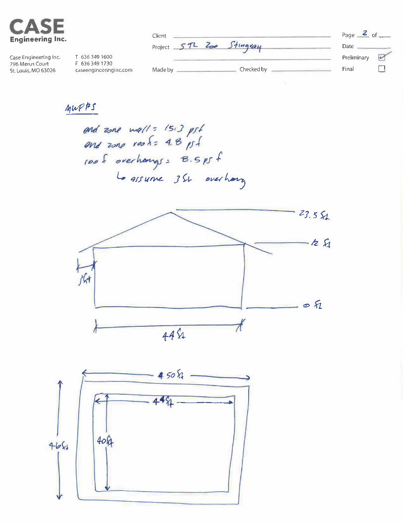
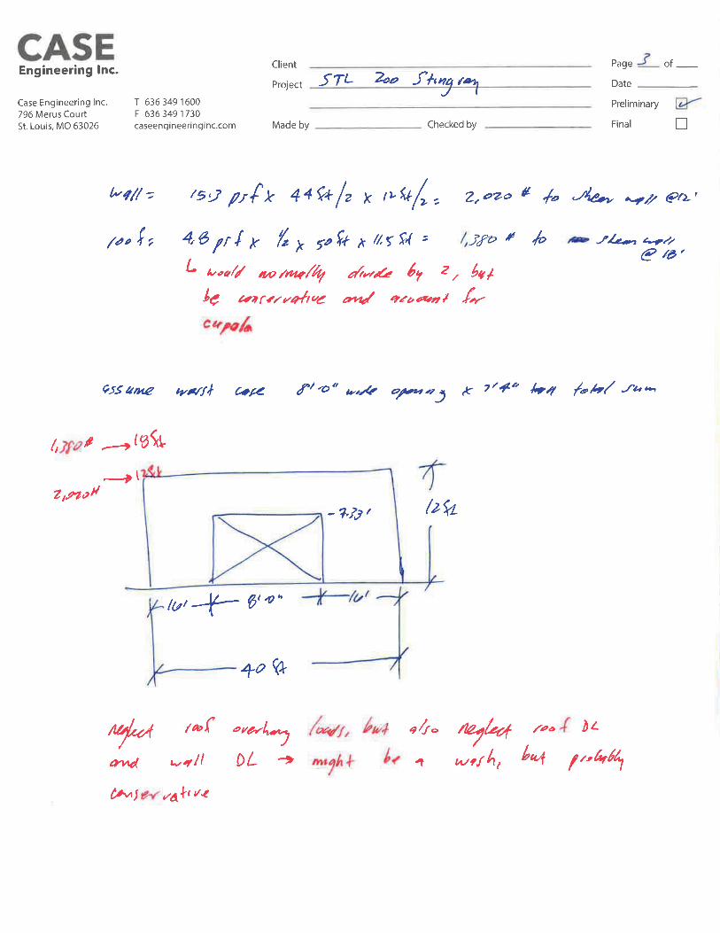
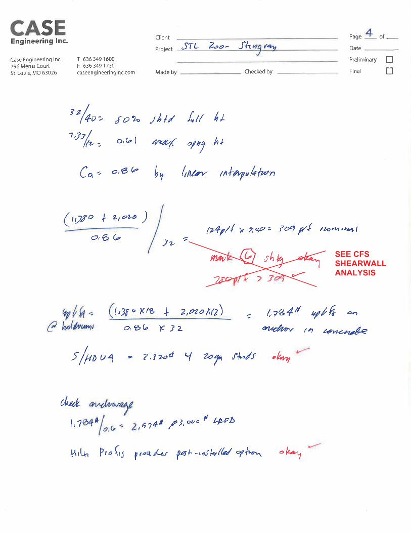
SEE CFSSHEARWALLANALYSIS


Load Data (Factored ASD)V(wind) =V(seismic) =
3400 lb974 lb
Chord Data
12 in
Chords: 600S162-54 (50) Back-To-Back
Shearwall Chord Force =
Additional Axial Loads =
KyLy, KtLt for Axial Capacity =Maximum KL/r =Allowable Axial Load =Input Chord Moment =
Flexural Bracing =
2160 lb
0 lb
162 in2312421 lb0 Ft-Lb
Full
Allowable Moment = 4317 Ft-LbChord Interaction = 0.892
Total Axial Loads = 2160 lb
2012 NASPEC [AISI S100-2012]Chord Fastener Spacing, a =
Includes Anchor Offset = 3.0 in
Overturning Uplift DataAnchor offset Each End =Uplift at Anchor - Wind =Uplift at Anchor - Seismic =
3.0 in2160 lb619 lb
Distortional Buckling Inputs for Moment and AxialK-phi =Lm =
0 lb-in/inNone
Tension Force: 2160 lbAllowable Tension: 3970 lbInteraction: 0.54
Holdown DataHoldown: S/HDU4 - (2) 54
Sheathing DataShear values per IBC 2012 (AISI S213-07/S1-09)See AISI S213-07/S1-09 for additional information
Stud Thickness =Sheathing:Fasteners:
Aspect Ratio =
54 mils0.018-inch Steel sheet, 1 side6-inches oc edges, 12-inches oc field
0.63:1
Unit Shear (Wind) =Allowable Unit Shear (Wind) =
158 lb/ft243 lb/ft
Unit Shear (Seismic) = 45 lb/ftAllowable Unit Shear (Seismic) = 156 lb/ft
Allowable Aspect Ratio for Seismic = 2.00:1Allowable Aspect Ratio for Wind = 2.00:1
Screws attaching panels to CFS steel framing shall comply withASTM C1513. Also, for framing members that are 54 mil andthinner, use minimum #8. For 68 mil and thicker, use min. #10.
www.strongtie.comSIMPSON STRONG-TIE COMPANY INC.
Project Name: St Louis Zoo Stingray Building - Light Gage DesignModel: Typical Shearwall
2012 NASPEC [AISI S100-2012]Code:
Page 1 of 1Date: 04/16/2021
Simpson Strong-Tie® CFS Designer™ 4.0.0.4

HEADER DESIGN
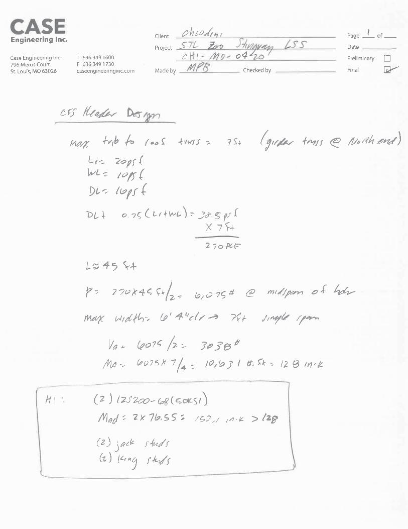


WALL STUD DESIGN

Section : 600S162-54 (50 ksi) @ 16" o.c. Single C Stud (punched)Maxo = 2527.1 ft-lb 2822.9 lbVa = I = 2.86 in^4
Loads have not been modified for strength checksLoads have been multiplied by 0.70 for deflection calculations
Bridging Connectors - Design Method =AISI S100
Span KyLy, KtLtFlexual,Distortional Connector
StressRatio
Axial
Span None, None None, 120.0" N/A -Web Crippling
Support Load (lb) (in) Max Int. Stiffener?Bearing Pa M
(lb) (ft-lbs)R2 80.7 --Shear Connection w/ clip-- NOR1 80.7 --Stud/Track Design, Ref Connectors-- NOGravity Load
Type Load (lb)Uniform 6.67plf
Code Check Required Interaction NotesAllowedMax. Axial, lbs 66.7(c) 5% KΦ=0.00 lb-in/in1416.7(c)Span
Max. Shear, lbs 80.7 4% Shear (Punched)1947.4Max. Moment (MaFy, Ma-dist), ft-lbs 201.7 9% Ma-dist (control),KΦ=0.00 lb-in/in2158.3
Moment Stability, ft-lbs 201.7 32%629.2Shear/Moment 0.08 8% Shear 0.0, Moment 201.71.00Axial/Moment 0.34 34% Axial 34.5(c), Moment 201.41.00
Deflection Span, in 0.030 --meets L/3985--
Support Rx(lb) Ry(lb) Simpson Strong-Tie ConnectorConnectorInteraction
AnchorInteraction
7.23 %R2 80.7 0.0 10.61 %SCB45.5(2) & (2) #12-24 SST X or XL to A36 Steel36.63 %R1 80.7 66.7 11.72 %600T125-33 (33) & (1) .157" SST PDPA/PDPAT-62KP to
steel (3/16" to 1/2" thickness)* Reference catalog for connector and anchor requirement notes as well as screw placement requirements
www.strongtie.comSIMPSON STRONG-TIE COMPANY INC.
Project Name: St Louis Zoo Stingray Building - Light Gage DesignModel: Typical Full Height Exterior Wall Stud
2012 NASPEC [AISI S100-2012]Code:
Page 1 of 1Date: 04/16/2021
Simpson Strong-Tie® CFS Designer™ 4.0.0.4

Section : (2) 600S162-54 (50 ksi) @ 16" o.c. Back-To-Back C Stud (punched)Maxo = 5054.2 ft-lb 5645.8 lbVa = I = 5.72 in^4
Loads have not been modified for strength checksLoads have been multiplied by 0.70 for deflection calculations
Bridging Connectors - Design Method =AISI S100
Span KyLy, KtLtFlexual,Distortional Connector
StressRatio
Axial
Span 48.0", 48.0" 48.0", 138.0" N/A -Web Crippling
Support Load (lb) (in) Max Int. Stiffener?Bearing Pa M
(lb) (ft-lbs)R2 92.8 --Shear Connection w/ clip-- NOR1 92.8 --Stud/Track Design, Ref Connectors-- NOGravity Load
Type Load (lb)Uniform 6.67plfP1y 6136lb @ 11.5ft
Code Check Required Interaction NotesAllowedMax. Axial, lbs 6212.7(c) 48% KΦ=0.00 lb-in/in12971.5(c)Span
Max. Shear, lbs 92.8 2% Shear (Punched)3894.8Max. Moment (MaFy, Ma-dist), ft-lbs 266.7 6% Ma-dist (control),KΦ=0.00 lb-in/in4316.7
Moment Stability, ft-lbs 266.7 6%4517.3Shear/Moment 0.05 5% Shear 0.0, Moment 266.71.00Axial/Moment 0.55 55% Axial 6175.2(c), Moment 266.61.00
Deflection Span, in 0.026 --meets L/5240--
Support Rx(lb) Ry(lb) Simpson Strong-Tie ConnectorConnectorInteraction
AnchorInteraction
8.32 %R2 92.8 0.0 12.21 %SCB45.5(2) & (2) #12-24 SST X or XL to A36 Steel42.13 %R1 92.8 6212.7 13.48 %600T125-33 (33) & (1) .157" SST PDPA/PDPAT-62KP to
steel (3/16" to 1/2" thickness)* Reference catalog for connector and anchor requirement notes as well as screw placement requirements
www.strongtie.comSIMPSON STRONG-TIE COMPANY INC.
Project Name: St Louis Zoo Stingray Building - Light Gage DesignModel: Double Jack Stud @ Truss Bearing
2012 NASPEC [AISI S100-2012]Code:
Page 1 of 1Date: 04/16/2021
Simpson Strong-Tie® CFS Designer™ 4.0.0.4

Section : 600S162-54 (50 ksi) @ 16" o.c. Single C Stud (punched)Maxo = 2527.1 ft-lb 2822.9 lbVa = I = 2.86 in^4
Loads have not been modified for strength checksLoads have been multiplied by 0.70 for deflection calculations
Bridging Connectors - Design Method =AISI S100
Span KyLy, KtLtFlexual,Distortional Connector
StressRatio
Axial
Span 48.0", 48.0" 48.0", 138.0" LSUBH3.25 (Min) 0.26Web Crippling
Support Load (lb) (in) Max Int. Stiffener?Bearing Pa M
(lb) (ft-lbs)R2 92.8 --Shear Connection w/ clip-- NOR1 92.8 --Stud/Track Design, Ref Connectors-- NOGravity Load
Type Load (lb)Uniform 6.67plfP1y 512lb @ 8ft
Code Check Required Interaction NotesAllowedMax. Axial, lbs 588.7(c) 10% KΦ=0.00 lb-in/in5712.2(c)Span
Max. Shear, lbs 92.8 5% Shear (Punched)1947.4Max. Moment (MaFy, Ma-dist), ft-lbs 266.7 12% Ma-dist (control),KΦ=0.00 lb-in/in2158.3
Moment Stability, ft-lbs 266.7 13%2083.5Shear/Moment 0.11 11% Shear 0.0, Moment 266.71.00Axial/Moment 0.22 22% Axial 551.3(c), Moment 266.51.00
Deflection Span, in 0.053 --meets L/2620--
Support Rx(lb) Ry(lb) Simpson Strong-Tie ConnectorConnectorInteraction
AnchorInteraction
8.32 %R2 92.8 0.0 12.21 %SCB45.5(2) & (2) #12-24 SST X or XL to A36 Steel42.13 %R1 92.8 588.7 13.48 %600T125-33 (33) & (1) .157" SST PDPA/PDPAT-62KP to
steel (3/16" to 1/2" thickness)* Reference catalog for connector and anchor requirement notes as well as screw placement requirements
www.strongtie.comSIMPSON STRONG-TIE COMPANY INC.
Project Name: St Louis Zoo Stingray Building - Light Gage DesignModel: Typical Full Height Exterior Wall Stud - w/ Mezzanine
2012 NASPEC [AISI S100-2012]Code:
Page 1 of 1Date: 04/16/2021
Simpson Strong-Tie® CFS Designer™ 4.0.0.4

MEZZANINE JOIST DESIGN

Section : 600S162-54 (50 ksi) @ 16 in" o.c. Single C Stud (punched)Maxo = 2527.1 ft-lb 2822.9 lbVa = I = 2.860 in^4
Total Load - 2401. DL + LL All spans2. DL + LL Even spans3. DL + LL Odd spans
Deflection Limits:Load Comb: 4. LL All spans
5. LL Even spans6. LL Odd spans
Live Load - 360
Mmax(ft-lb)
K-phi(lb-in/in)
Lm(in)
Ma-dist(ft-lb)
Mmax/Ma min
LoadComb.
TLDefl
LoadComb.
LLDefl
LoadComb.
Joist Flexural and Deflection
Span 898 0.0 84.0 2158.3 0.416 1 L/895 1 L/984 4
SupportLoad(lb)
Bearing(in)
Pa(lb)
Pn(lb)
MaxIntr.
LoadComb.
StiffenersRequired
Joist Bending and Web Crippling
LoadComb.
R1 513.3 1.00 598.9 1048.1 0.45 1 NO1R2 513.3 1.00 598.9 1048.1 0.45 1 NO1
SupportVmax(lb)
LoadComb.
VaFactor V/Va M/Ma
Intr.Unstiffened
Intr.Stiffened
Joist Bending and Shear
LoadComb.
LoadComb.
R1 513.3 1 0.18 0.00 0.18 N/A1.000 1 N/AR2 513.3 1 0.18 0.00 0.18 N/A1.000 1 N/A
Support Rx(lb) Ry(lb) Simpson Strong-Tie ConnectorConnectorInteraction
AnchorInteraction
Joist Reaction and Connections
0.00 %R1 0.0 513.3 0.00 %SSC4.25 (4#10) & (3) #10 to A36 steel (Bearing Attached)0.00 %R2 0.0 513.3 0.00 %SSC4.25 (4#10) & (3) #10 to A36 steel (Bearing Attached)
www.strongtie.comSIMPSON STRONG-TIE COMPANY INC.
Project Name: St Louis Zoo Stingray Building - Light Gage DesignModel: Mezzanine Floor Joist
2012 NASPEC [AISI S100-2012]Code:
Page 1 of 2Date: 04/16/2021
Simpson Strong-Tie® CFS Designer™ 4.0.0.4
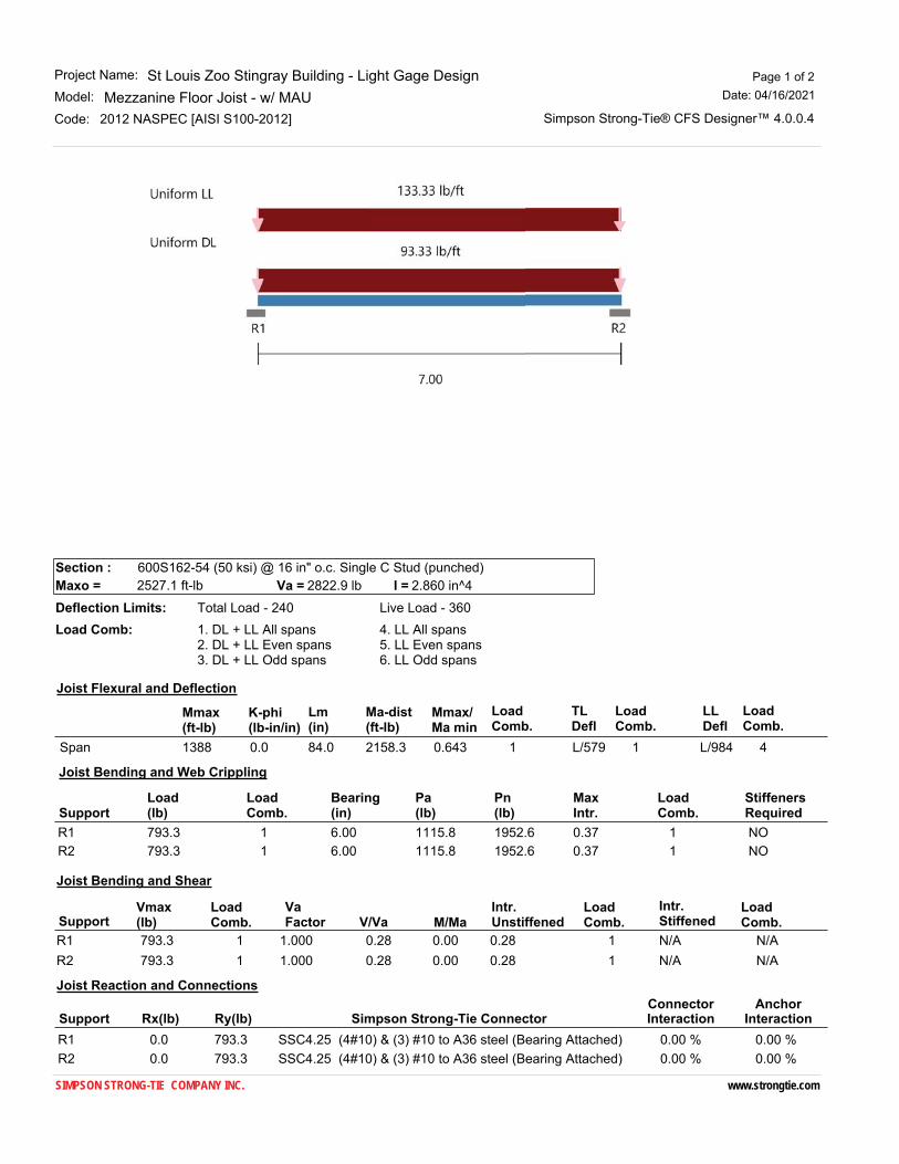
Section : 600S162-54 (50 ksi) @ 16 in" o.c. Single C Stud (punched)Maxo = 2527.1 ft-lb 2822.9 lbVa = I = 2.860 in^4
Total Load - 2401. DL + LL All spans2. DL + LL Even spans3. DL + LL Odd spans
Deflection Limits:Load Comb: 4. LL All spans
5. LL Even spans6. LL Odd spans
Live Load - 360
Mmax(ft-lb)
K-phi(lb-in/in)
Lm(in)
Ma-dist(ft-lb)
Mmax/Ma min
LoadComb.
TLDefl
LoadComb.
LLDefl
LoadComb.
Joist Flexural and Deflection
Span 1388 0.0 84.0 2158.3 0.643 1 L/579 1 L/984 4
SupportLoad(lb)
Bearing(in)
Pa(lb)
Pn(lb)
MaxIntr.
LoadComb.
StiffenersRequired
Joist Bending and Web Crippling
LoadComb.
R1 793.3 6.00 1115.8 1952.6 0.37 1 NO1R2 793.3 6.00 1115.8 1952.6 0.37 1 NO1
SupportVmax(lb)
LoadComb.
VaFactor V/Va M/Ma
Intr.Unstiffened
Intr.Stiffened
Joist Bending and Shear
LoadComb.
LoadComb.
R1 793.3 1 0.28 0.00 0.28 N/A1.000 1 N/AR2 793.3 1 0.28 0.00 0.28 N/A1.000 1 N/A
Support Rx(lb) Ry(lb) Simpson Strong-Tie ConnectorConnectorInteraction
AnchorInteraction
Joist Reaction and Connections
0.00 %R1 0.0 793.3 0.00 %SSC4.25 (4#10) & (3) #10 to A36 steel (Bearing Attached)0.00 %R2 0.0 793.3 0.00 %SSC4.25 (4#10) & (3) #10 to A36 steel (Bearing Attached)
www.strongtie.comSIMPSON STRONG-TIE COMPANY INC.
Project Name: St Louis Zoo Stingray Building - Light Gage DesignModel: Mezzanine Floor Joist - w/ MAU
2012 NASPEC [AISI S100-2012]Code:
Page 1 of 2Date: 04/16/2021
Simpson Strong-Tie® CFS Designer™ 4.0.0.4

RETAINING WALL PERIMETETERFOUNDATION DESIGN
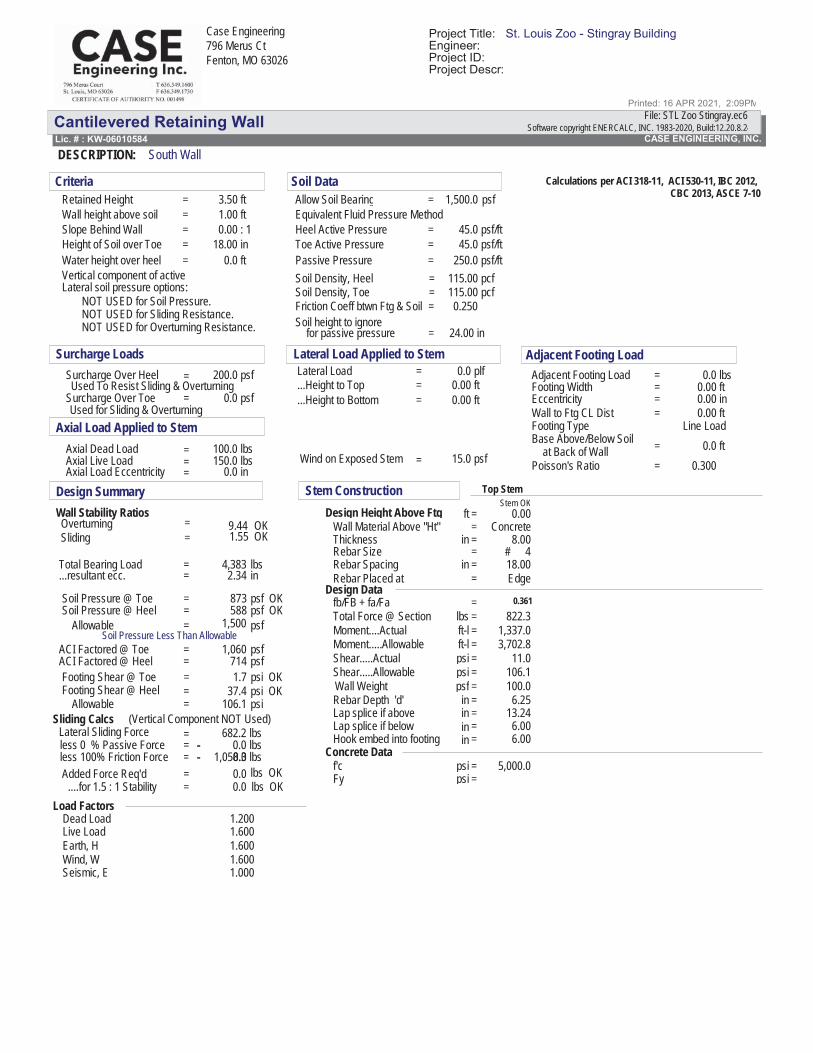
Cantilevered Retaining WallCASE ENGINEERING, INC.Lic. # : KW-06010584
DESCRIPTION: South Wall
Case Engineering796 Merus CtFenton, MO 63026
Software copyright ENERCALC, INC. 1983-2020, Build:12.20.8.24File: STL Zoo Stingray.ec6
Project Title: St. Louis Zoo - Stingray BuildingEngineer:Project ID:
Printed: 16 APR 2021, 2:09PM
Project Descr:
Calculations per ACI 318-11, ACI 530-11, IBC 2012,CBC 2013, ASCE 7-103.50
1.000.00
18.00
1,500.0
45.0
0.045.0 psf/ft
250.0
Criteria Soil DataRetained Height = ftWall height above soil = ft
Heel Active Pressure = psf/ft: 1Slope Behind WallHeight of Soil over Toe
=
inWater height over heel = ft
pcfpcf= 115.00
=
115.00
=
Soil Density, Heel
Toe Active Pressure =Passive Pressure = psf/ft
Allow Soil Bearing = psf
Soil Density, Toe
Soil height to ignoreFriction Coeff btwn Ftg & Soil = 0.250
Vertical component of activeLateral soil pressure options:
NOT USED for Soil Pressure.NOT USED for Sliding Resistance.NOT USED for Overturning Resistance. for passive pressure = 24.00 in
Equivalent Fluid Pressure Method
Surcharge Loads Adjacent Footing Load200.0 Lateral Load = 0.0 plf
0.0
100.0150.0
0.0
Axial Load Applied to StemWall to Ftg CL Dist = 0.00 ft
Wind on Exposed Stem psf15.0=
Lateral Load Applied to StemSurcharge Over Heel = psf Adjacent Footing Load = 0.0 lbs
Axial Dead Load = lbs
Footing Type Line Load
Surcharge Over Toe psfFooting Width = 0.00 ft...Height to Top = 0.00 ftEccentricity = 0.00 in...Height to Bottom = 0.00 ft
Used To Resist Sliding & Overturning
Used for Sliding & Overturning
= 0.0 ftAxial Live Load =
Base Above/Below Soil
lbs
=
Axial Load Eccentricity = =Poisson's Ratio 0.300at Back of Wall
inDesign SummaryWall Stability RatiosOverturning = 9.44 OKSliding = 1.55 OK
Total Bearing Load = 4,383 lbs...resultant ecc. = 2.34 in
Soil Pressure @ Toe = 873 psf OKSoil Pressure @ Heel = 588 psf OK
Allowable = 1,500 psfSoil Pressure Less Than Allowable
ACI Factored @ Toe = 1,060 psfACI Factored @ Heel = 714 psfFooting Shear @ Toe = 1.7 psi OKFooting Shear @ Heel = 37.4 psi OK
Allowable = 106.1 psiSliding Calcs (Vertical Component NOT Used)
Lateral Sliding Force = 682.2 lbsless 0 % Passive Forceless 100% Friction ForceAdded Force Req'd
....for 1.5 : 1 Stability =0.0=
1,058.30.00.0
==
0.0
-lbslbslbs OKlbs OK
-
Stem Construction Top StemStem OK
Design Height Above Ftg = 0.00ftWall Material Above "Ht" = ConcreteThickness = 8.00inRebar Size = # 4Rebar Spacing = 18.00inRebar Placed at = Edge
Design Datafb/FB + fa/Fa = 0.361Total Force @ Section = 822.3lbsMoment....Actual = 1,337.0ft-lMoment.....Allowable = 3,702.8ft-lShear.....Actual = 11.0psiShear.....Allowable = 106.1psi
Lap splice if above = 13.24in6.00in
Hook embed into footing 6.00=in
Wall Weight = 100.0
Lap splice if below =
psfRebar Depth 'd' = 6.25in
Concrete Dataf'c = 5,000.0psiFy =
Load FactorsDead Load 1.200Live Load 1.600Earth, H 1.600Wind, W 1.600Seismic, E 1.000
psi
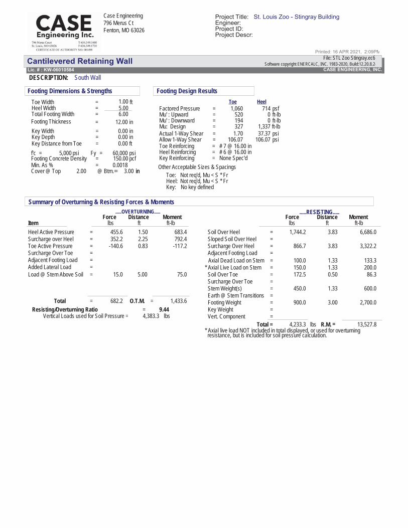
Cantilevered Retaining WallCASE ENGINEERING, INC.Lic. # : KW-06010584
DESCRIPTION: South Wall
Case Engineering796 Merus CtFenton, MO 63026
Software copyright ENERCALC, INC. 1983-2020, Build:12.20.8.24File: STL Zoo Stingray.ec6
Project Title: St. Louis Zoo - Stingray BuildingEngineer:Project ID:
Printed: 16 APR 2021, 2:09PM
Project Descr:
1.005.00
12.000.000.00
=Min. As % 0.0018
Footing Dimensions & Strengths
f'c = 5,000 psi
Toe Width = ftHeel Width =
Key Distance from ToeKey DepthKey Width = in
= in= 0.00
Footing Thickness = in6.00=
ft
Cover @ Top =2.00 in@ Btm.= 3.00 in
Total Footing Width
= 150.00 pcfFooting Concrete DensityFy = 60,000 psi
Footing Design Results
Key:
=
No key defined
Factored PressureMu' : UpwardMu' : DownwardMu: DesignActual 1-Way ShearAllow 1-Way Shear
Toe: Not req'd, Mu < S * FrNot req'd, Mu < S * Fr
= None Spec'd
==
===
1,0605201943271.70
106.07
Heel:
71400
1,33737.37
106.07
HeelToepsfft-lbft-lbft-lbpsipsi
Heel Reinforcing = # 6 @ 16.00 in
Other Acceptable Sizes & SpacingsKey Reinforcing
Toe Reinforcing = # 7 @ 16.00 in
Summary of Overturning & Resisting Forces & Moments.....RESISTING..........OVERTURNING.....
Force Distance Moment Distance MomentItem
Force
Soil Over Heelft-lb
455.6 1,744.2lbs
683.4
-140.6Toe Active Pressure
1.50 3.83ftft
6,686.0=Heel Active Pressureft-lblbs
Sloped Soil Over Heel=
792.42.25352.2=Surcharge over Heel =Surcharge Over Heel
=
866.7 3.83 3,322.2=
Adjacent Footing Load=Adjacent Footing Load
Axial Dead Load on Stem = 100.0 1.33 133.3= 150.0 1.33 200.0* Axial Live Load on Stem
Soil Over ToeSurcharge Over Toe
Surcharge Over Toe
Load @ Stem Above Soil = 15.0 5.00 75.0
==
0.83 -117.2
172.5 0.50 86.3=
==
Stem Weight(s)=
450.0 1.33 600.0Earth @ Stem Transitions
=Footing Weight=
900.0 3.00 2,700.0Key Weight
=Added Lateral Load
lbs
= 1,433.6
Vert. Component
Total
=4,233.3 13,527.8
* Axial live load NOT included in total displayed, or used for overturningresistance, but is included for soil pressure calculation.
Total = R.M.
=682.2 O.T.M.
=
Resisting/Overturning Ratio = 9.44Vertical Loads used for Soil Pressure = 4,383.3 lbs

Chiodini ArchitectsSaint Louis Zoo - Stingray LSS
BuildingProject Number: 2020.020 Missouri,St Louis
Summary 01 1000 - 1
SECTION 01 1000 - SUMMARYPART 1 GENERAL
1.1 PROJECTA. Project Name: Saint Louis Zoo - Stingray LSS BuildingB. Owner's Name: Saint Louis Zoo.C. Architect's Name: Chiodini Architects.D. The Project consists of the construction of a zoo exhibit support building and related elements .
1.2 CONTRACT DESCRIPTIONA. Contract Type: A single prime contract based on a Stipulated Price.
1.3 DESCRIPTION OF ALTERATIONS WORKA. Scope of demolition and removal work is indicated on drawings .
1.4 CONCURRANT WORKA. Concurrant Work to occur under seperate contracts refered to by the following.
1. By Others2. Not in Contract (NIC)3. Owner's Agent4. Owner's Forces
B. Owners Agent: Owner will award a contract for supply and installation of Stingray Life Supports SystemsEquipment which will commence on or around Substantial Completion.1. Owners Agent: Living Exhibits
C. Owner's Forces: Owner's Forces may install and/or maintain plant material or landscape on or arroundthe Project Site. Contractor is responsible for coordinating those opporations simultaneously with workunder this contract. If any of the Concurrent Work threatens the completion of the Project Work
1.5 WORK BY OWNERA. Concurrent Work: General: Owner will award a contract for supply and installation of Stingray Life
Supports Systems Equipment which will commence on or around Substantial Completion.B. Items noted NIC (Not in Contract) or BY OTHERS will be supplied and installed by Owner or Owner's
Agent before Substantial Completion. Some items include:1. Living Exhibits: Stingray Life Support Systems Equipment, including, but not limited to, items
noted on drawings .2. Furnishings.3. Equipment.
C. Owner will Furnish the following for Contractor Installation (OFCI):1. Select Toilet Accessories as noted in drawings .
1.6 OWNER OCCUPANCYA. Owner or Owner's Agent intends to occupy the Project upon Substantial Completion.B. Cooperate with Owner or Owner's Agent to minimize conflict and to facilitate operations.C. Schedule the Work to accommodate Owner or Owner's Agent occupancy.
1.7 CONTRACTOR USE OF SITE AND PREMISESA. Construction Operations: Limited to areas noted on Drawings.
1. Locate and conduct construction activities in ways that will limit disturbance to site.B. Arrange use of site and premises to allow:
1. Work by Others.2. Work by Owner.3. Work by Onner's Agent
C. Provide access to and from site as required by law and by Owner:1. Emergency Building Exits During Construction: Keep all exits required by code open during
construction period; provide temporary exit signs if exit routes are temporarily altered.

Chiodini ArchitectsSaint Louis Zoo - Stingray LSS
BuildingProject Number: 2020.020 Missouri,St Louis
Summary 01 1000 - 2
2. Do not obstruct roadways, sidewalks, or other public ways without permit.D. Existing building spaces may not be used for storage.
1. Unless specifically noted in the Contract Documents.2. Unless prior approval optained in writing.
E. Utility Outages and Shutdown:1. Prevent accidental disruption of utility services to other facilities.
1.8 SEQUENCE OF EVENTS / DATES OF IMPORTANCEA. The following is the proposed sequence of Construction (Post Bid) and is subject to approval by the
Owner.1. Notice to Proceed: Mid-July, 20212. Mobilization: Mid-July - September, 2021
a. Pre-Construction Meeting1) Contractor access proticals2) Contractor storage areas
b. Zoo Safety Meetingc. Zoo Security Meeting
3. Stingrays Move Out (By Others): October 6, 20214. Stingray LSS Equipment Removed (By Others): October 11, 20215. Site turned over to Contractor: October 18, 20216. Substantial Completion: February 18, 20227. MEP verification for LSS Equipment (All): February 21, 20228. Stingray LSS Equipment Intallation (By Others): February 28, 20229. Stingrays Move In (By Others) April 8, 2022
PART 2 PRODUCTS - NOT USED
PART 3 EXECUTION - NOT USED
END OF SECTION

Chiodini ArchitectsSaint Louis Zoo - Stingray LSS
BuildingProject Number: 2020.020 Missouri,St Louis
Price and Payment Procedures 01 2000 - 1
SECTION 01 2000 - PRICE AND PAYMENT PROCEDURESPART 1 GENERAL
1.1 SECTION INCLUDESA. Procedures for preparation and submittal of applications for progress payments.B. Documentation of changes in Contract Sum and Contract Time.C. Change procedures.D. Correlation of Contractor submittals based on changes.E. Procedures for preparation and submittal of application for final payment.
1.2 RELATED REQUIREMENTSA. Saint Louis Zoo Front End
1. Agreement: Contract Sum, Retainages, Payment Period, monetary values of Unit Prices ifrequested.
2. General Conditions: Additional requirements for Progress Payments, Final Payment, Changes inthe Work.
3. Supplementary Conditions: Percentage Allowances for Contractor's Overhead and Profit.B. Section 01 2200 - Unit Prices: Monetary values of unit prices; Payment and modification procedures
relating to unit prices.C. Section 01 7800 - Closeout Submittals: Project record documents.
1.3 SCHEDULE OF VALUESA. Use Schedule of Values Form: AIA G703, edition stipulated in the Agreement.B. Use the Table of Contents of this Project Manual as a format to identity each line items with number
and title of the specifaction section.C. Electronic media printout including equivalent information will be considered in lieu of standard form
specified; submit draft to Architect for approval.D. Forms filled out by hand will not be accepted.E. Submit Schedule of Values [______] within 15 days after date of Owner-Contractor Agreement .F. Include in each line item, the amount of Allowances specified in this section. For unit cost Allowances,
identify quantities taken from Contract Documents multiplied by the unit cost to achieve the total forthe item.
G. Revise schedule to list approved Change Orders, with each Application For Payment.1.4 APPLICATIONS FOR PROGRESS PAYMENTS
A. Payment Period: Pay Applications shall be made monthly. Applications should be submitted by the 25thday of the month..1. Applications will be authorized for payment at the Owner's Board of Trustees meeting of the
following month.2. The Contractor should not expect to receive payment untill the month following the Board of
Trustees meeting authorization.B. Use Form AIA G702 and Form AIA G703, edition stipulated in the Agreement.C. Electronic media printout including equivalent information will be considered in lieu of standard form
specified; submit sample to Architect for approval.D. Forms filled out by hand will not be accepted.E. For each item, provide a column for listing each of the following:
1. Item Number.2. Description of work.3. Scheduled Values.4. Previous Applications.5. Work in Place and Stored Materials under this Application.6. Authorized Change Orders.
Chiodini ArchitectsSaint Louis Zoo - Stingray LSS
BuildingProject Number: 2020.020 Missouri,St Louis
Price and Payment Procedures 01 2000 - 2
7. Total Completed and Stored to Date of Application.8. Percentage of Completion.9. Balance to Finish.10. Retainage.
F. Execute certification by signature of authorized officer.G. Use data from approved Schedule of Values. Provide dollar value in each column for each line item for
portion of work performed and for stored products.H. List each authorized Change Order as a separate line item, listing Change Order number and dollar
amount as for an original item of work.I. Submit one electronic and three hard-copies of each Application for Payment.J. Include the following with the application:
1. Construction progress schedule, revised and current as specified in Section 01 3000.2. Current construction photographs specified in Section 01 3000.3. Partial release of liens from major subcontractors and vendors.4. Affidavits attesting to off-site stored products.
K. When Architect requires substantiating information, submit data justifying dollar amounts in question. Provide one copy of data with cover letter for each copy of submittal. Show application number anddate, and line item by number and description.
1.5 MODIFICATION PROCEDURESA. For minor changes not involving an adjustment to the Contract Sum or Contract Time, Architect will
issue instructions directly to Contractor.B. For other required changes, Architect will issue a document signed by Owner instructing Contractor to
proceed with the change, for subsequent inclusion in a Change Order.1. The document will describe the required changes and will designate method of determining any
change in Contract Sum or Contract Time.2. Promptly execute the change.
C. Proposal Request: For changes for which advance pricing is desired, Architect will issue a document thatincludes a detailed description of a proposed change with supplementary or revised drawings andspecifications, a change in Contract Time for executing the change with a stipulation of any overtimework required and the period of time during which the requested price will be considered valid.Contractor shall prepare and submit a fixed price quotation within [____] days.
D. Change Order Request: Contractor may propose a change by submitting a request for change toArchitect, describing the proposed change and its full effect on the work, with a statement describingthe reason for the change, and the effect on the Contract Sum and Contract Time with fulldocumentation. Document any requested substitutions in accordance with Section 01 6000.
E. Computation of Change in Contract Amount: As specified in the Agreement and Conditions of theContract.1. For change requested by Architect for work falling under a fixed price contract, the amount will be
based on Contractor's price quotation.2. For change requested by Contractor, the amount will be based on the Contractor's request for a
Change Order as approved by Architect.3. For pre-determined unit prices and quantities, the amount will based on the fixed unit prices.4. For change ordered by Architect without a quotation from Contractor, the amount will be
determined by Architect based on the Contractor's substantiation of costs as specified for Timeand Material work.
F. Substantiation of Costs: Provide full information required for evaluation.1. On request, provide the following data:
a. Quantities of products, labor, and equipment.b. Taxes, insurance, and bonds.
Chiodini ArchitectsSaint Louis Zoo - Stingray LSS
BuildingProject Number: 2020.020 Missouri,St Louis
Price and Payment Procedures 01 2000 - 3
c. Overhead and profit.d. Justification for any change in Contract Time.e. Credit for deletions from Contract, similarly documented.
2. Support each claim for additional costs with additional information:a. Origin and date of claim.b. Dates and times work was performed, and by whom.c. Time records and wage rates paid.d. Invoices and receipts for products, equipment, and subcontracts, similarly documented.
3. For Time and Material work, submit itemized account and supporting data after completion ofchange, within time limits indicated in the Conditions of the Contract.
G. Execution of Change Orders: Architect will issue Change Orders for signatures of parties as provided inthe Conditions of the Contract.
H. After execution of Change Order, promptly revise Schedule of Values and Application for Paymentforms to record each authorized Change Order as a separate line item and adjust the Contract Sum.
I. Promptly revise progress schedules to reflect any change in Contract Time, revise sub-schedules toadjust times for other items of work affected by the change, and resubmit.
J. Promptly enter changes in Project Record Documents.1.6 APPLICATION FOR FINAL PAYMENT
A. Prepare Application for Final Payment as specified for progress payments, identifying total adjustedContract Sum, previous payments, and sum remaining due.
B. Application for Final Payment will not be considered until the following have been accomplished:1. All closeout procedures specified in Section 01 7000.
PART 2 PRODUCTS - NOT USED
PART 3 EXECUTION - NOT USED
END OF SECTION
Chiodini ArchitectsSaint Louis Zoo - Stingray LSS
BuildingProject Number: 2020.020 Missouri,St Louis
Unit Prices 01 2200 - 1
SECTION 01 2200 - UNIT PRICESPART 1 GENERAL
1.1 SECTION INCLUDESA. List of unit prices, for use in preparing Bids.B. Measurement and payment criteria applicable to Work performed under a unit price payment method.C. Defect assessment and non-payment for rejected work.
1.2 COSTS INCLUDEDA. Unit Prices included on the Bid Form shall include full compensation for all required labor, products,
tools, equipment, plant, transportation, services and incidentals; erection, application or installation ofan item of the Work; overhead and profit.
1.3 UNIT QUANTITIES SPECIFIEDA. Quantities indicated in the Bid Form are for bidding and contract purposes only. Quantities and
measurements of actual Work will determine the payment amount.1.4 MEASUREMENT OF QUANTITIES
A. Measurement methods delineated in the individual specification sections complement the criteria ofthis section. In the event of conflict, the requirements of the individual specification section govern.
B. Take all measurements and compute quantities. Measurements and quantities will be verified byOwner.
C. Assist by providing necessary equipment, workers, and survey personnel as required.D. Measurement by Volume: Measured by cubic dimension using mean length, width and height or
thickness.E. Perform surveys required to determine quantities, including control surveys to establish measurement
reference lines. Notify Architect prior to starting work.1.5 PAYMENT
A. Payment for Work governed by unit prices will be made on the basis of the actual measurements andquantities of Work that is incorporated in or made necessary by the Work and accepted by theArchitect, multiplied by the unit price.
B. Payment will not be made for any of the following:1. Products wasted or disposed of in a manner that is not acceptable.2. Products determined as unacceptable before or after placement.3. Products not completely unloaded from the transporting vehicle.4. Products placed beyond the lines and levels of the required Work.5. Products remaining on hand after completion of the Work.6. Loading, hauling, and disposing of rejected Products.
1.6 DEFECT ASSESSMENTA. Replace Work, or portions of the Work, not complying with specified requirements.B. If, in the opinion of Owner, it is not practical to remove and replace the Work, Owner will direct one of
the following remedies:1. The defective Work may remain, but the unit price will be adjusted to a new unit price at the
discretion of Owner.2. The defective Work will be partially repaired to the instructions of the Owner, and the unit price
will be adjusted to a new unit price at the discretion of Owner.C. The individual specification sections may modify these options or may identify a specific formula or
percentage price reduction.D. The authority of Owner to assess the defect and identify payment adjustment is final.
1.7 SCHEDULE OF UNIT PRICESA. Item: Unit Price 01 - Removal of Unsuitable Soils, Off-Site Disposal and Replacement with
Suitable Soil or Fill Compacted In-Place ; Section 31 2000 .

Chiodini ArchitectsSaint Louis Zoo - Stingray LSS
BuildingProject Number: 2020.020 Missouri,St Louis
Unit Prices 01 2200 - 2
B. Item: Unit Price 02 - Removal of Rock, Off-Site Disposal and Replacement with Suitable Soil or FillCompacted In-Place ; Section 31 2316.26 .
PART 2 PRODUCTS - NOT USED
PART 3 EXECUTION - NOT USED
END OF SECTION
Chiodini ArchitectsSaint Louis Zoo - Stingray LSS
BuildingProject Number: 2020.020 Missouri,St Louis
Alternates 01 2300 - 1
SECTION 01 2300 - ALTERNATESPART 1 GENERAL
1.1 SECTION INCLUDESA. Description of Alternates.B. Procedures for pricing Alternates.
1.2 ACCEPTANCE OF ALTERNATESA. Alternates quoted on Bid Forms will be reviewed and accepted or rejected at Owner's option. Accepted
Alternates will be identified in the Owner-Contractor Agreement.B. Coordinate related work and modify surrounding work to integrate the Work of each Alternate.C. Included in Alternate price: All labor, materials, parts and accessories required for a complete
imstallation, regardless of whether they are mentioned in teh alternate descirption.1.3 SCHEDULE OF ALTERNATES
A. Alternate No. 01 - Epoxy Coated Reinforcement :1. Base Bid Scope: Standard Steel Bar Foundation Wall and Footing Reinforcement.2. Alternate Bid Scope: Epoxy Coated Steel Bar Foundation Wall and Footing Reinforcement.
B. Alternate No. 02 - Fiberglass Truss and Deck Resin :1. Base Bid Scope: Provide Fiberglass Truss fabricated with Fire-Retardand Polyester Resin and 316
stainless steel fasteners.2. Alternate Bid Scope: Provide Fiberglass Truss fabricated with Fire-Retardand Vinylester Resin and
316 stainless steel fasteners.C. Alternate No. 03 - Interior FRP Faced Insulated Metal Wall Panel :
1. Base Bid Scope: Provide Interior Insulated Metal Wall Panels - CF Santa Fe, manufactured byMetlSpan.
2. Alternate Bid Scope: Interior Insulated Metal Wall Panels - FRP Clean Seam manufactured byMetlSpan.
D. Alternate No. 04 - Fiberglass Doors and Frames :1. Base Bid Scope: Provide galvanized hollow metal doors and frames, installed per drawings and
manufacturers requirements.2. Alternate Bid Scope: Provide fiberglass doors and frames, installed per manufacturers
requirements. Provide suggested revisions to drawings details to architect.E. Alternate No. 05 - Electric Air Curtains:
1. Base Bid Scope: Provide Plastic Stip Door Curtains as shown on drawings. Face mounted to doorhead per manufacturers requirements.
2. Alternate Bid Scope: Provide Electrice Air Curtains and Switches as shown on drawings. Facemounted to door head per manufacturers requirements. Provide required conduit and hardwireelectrical connection. Coordinate electrical junction box location with structural door header.
PART 2 PRODUCTS - NOT USED
PART 3 EXECUTION - NOT USED
END OF SECTION
Chiodini ArchitectsSaint Louis Zoo - Stingray LSS
BuildingProject Number: 2020.020 Missouri,St Louis
Substitution Procedures 01 2500 - 1
SECTION 01 2500 - SUBSTITUTION PROCEDURESPART 1 GENERAL
1.1 SECTION INCLUDESA. Procedural requirements for proposed substitutions.
1.2 RELATED REQUIREMENTSA. Section 01 2200 - Unit Prices, for additional unit price requirements.B. Section 01 2300 - Alternates, for product alternatives affecting this section.C. Section 01 3000 - Administrative Requirements: Submittal procedures, coordination.D. Section 01 6000 - Product Requirements: Fundamental product requirements, product options,
delivery, storage, and handling.E. Section 01 6116 - Volatile Organic Compound (VOC) Content Restrictions: Restrictions on emissions of
indoor substitute products.1.3 DEFINITIONS
A. Substitutions: Changes from Contract Documents requirements proposed by Contractor to materials,products, assemblies, and equipment.1. Substitutions for Cause: Proposed due to changed Project circumstances beyond Contractor's
control.a. Unavailability.b. Regulatory changes.
2. Substitutions for Convenience: Proposed due to possibility of offering substantial advantage tothe Project.a. Substitution requests offering advantages solely to the Contractor will not be considered.
PART 2 PRODUCTS - NOT USED
PART 3 EXECUTION
3.1 GENERAL REQUIREMENTSA. A Substitution Request for products, assemblies, materials, and equipment constitutes a representation
that the submitter:1. Has investigated proposed product and determined that it meets or exceeds the quality level of
the specified product, equipment, assembly, or system.2. Agrees to provide the same warranty for the substitution as for the specified product.3. Agrees to provide same or equivalent maintenance service and source of replacement parts, as
applicable.4. Agrees to coordinate installation and make changes to other work that may be required for the
work to be complete, with no additional cost to Owner.5. Waives claims for additional costs or time extension that may subsequently become apparent.6. Agrees to reimburse Owner and Architect for review or redesign services associated with re-
approval by authorities.B. A Substitution Request for specified installer constitutes a representation that the submitter:
1. Has acted in good faith to obtain services of specified installer, but was unable to come tocommercial, or other terms.
C. Document each request with complete data substantiating compliance of proposed substitution withContract Documents. Burden of proof is on proposer.1. Note explicitly any non-compliant characteristics.
D. Content: Include information necessary for tracking the status of each Substitution Request, andinformation necessary to provide an actionable response.
Chiodini ArchitectsSaint Louis Zoo - Stingray LSS
BuildingProject Number: 2020.020 Missouri,St Louis
Substitution Procedures 01 2500 - 2
1. No specific form is required. Contractor's Substitution Request documentation must include thefollowing:a. Project Information:
1) Official project name and number, and any additional required identifiers established inContract Documents.
2) Owner's, Architect's, and Contractor's names.b. Substitution Request Information:
1) Discrete and consecutive Substitution Request number, and descriptive subject/title.2) Indication of whether the substitution is for cause or convenience.3) Issue date.4) Reference to particular Contract Document(s) specification section number, title, and
article/paragraph(s).5) Description of Substitution.6) Reason why the specified item cannot be provided.7) Differences between proposed substitution and specified item.8) Description of how proposed substitution affects other parts of work.
c. Attached Comparative Data: Provide point-by-point, side-by-side comparison addressingessential attributes specified, as appropriate and relevant for the item:1) Physical characteristics.2) Expected durability.3) Visual effect.4) Sustainable design features.5) Warranties.6) Other salient features and requirements.7) Include, as appropriate or requested, the following types of documentation:
(a) Product Data:(b) Samples.(c) Certificates, test, reports or similar qualification data.(d) Drawings, when required to show impact on adjacent construction elements.
d. Impact of Substitution:1) Savings to Owner for accepting substitution.2) Change to Contract Time due to accepting substitution.
E. Limit each request to a single proposed substitution item.1. Submit an electronic document, combining the request form with supporting data into single
document.3.2 SUBSTITUTION PROCEDURES DURING PROCUREMENT
A. Submittal Time Restrictions:1. Owner will consider requests for substitutions only if submitted at least 10 days prior to the date
for receipt of bids.3.3 SUBSTITUTION PROCEDURES DURING CONSTRUCTION
A. Architect will consider requests for substitutions only within 15 days after date of Agreement.B. Submit request for Substitution for Cause within 14 days of discovery of need for substitution, but not
later than 14 days prior to time required for review and approval by Architect, in order to stay onapproved project schedule.
C. Submit request for Substitution for Convenience immediately upon discovery of its potential advantageto the project, but not later than 14 days prior to time required for review and approval by Architect, inorder to stay on approved project schedule.1. In addition to meeting general documentation requirements, document how the requested
substitution benefits the Owner through cost savings, time savings, greater energy conservation,
Chiodini ArchitectsSaint Louis Zoo - Stingray LSS
BuildingProject Number: 2020.020 Missouri,St Louis
Substitution Procedures 01 2500 - 3
or in other specific ways.2. Document means of coordinating of substitution item with other portions of the work, including
work by affected subcontractors.3. Bear the costs engendered by proposed substitution of:
a. Owner's compensation to the Architect for any required redesign, time spent processing andevaluating the request.
b. Other construction by Owner.c. Other unanticipated project considerations.
D. Substitutions will not be considered under one or more of the following circumstances:1. When they are indicated or implied on shop drawing or product data submittals, without having
received prior approval.2. Without a separate written request.
3.4 RESOLUTIONA. Architect may request additional information and documentation prior to rendering a decision. Provide
this data in an expeditious manner.B. Architect will notify Contractor in writing of decision to accept or reject request.
1. Architect's decision following review of proposed substitution will be noted on the submittedform.
3.5 ACCEPTANCEA. Accepted substitutions change the work of the Project. They will be documented and incorporated into
work of the project by Change Order, Construction Change Directive, Architectural SupplementaryInstructions, or similar instruments provided for in the Conditions of the Contract.
3.6 CLOSEOUT ACTIVITIESA. See Section 01 7800 - Closeout Submittals, for closeout submittals.B. Include completed Substitution Request Forms as part of the Project record. Include both approved and
rejected Requests.END OF SECTION
Chiodini ArchitectsSaint Louis Zoo - Stingray LSS
BuildingProject Number: 2020.020 Missouri,St Louis
Administrative Requirements 01 3000 - 1
SECTION 01 3000 - ADMINISTRATIVE REQUIREMENTSPART 1 GENERAL
1.1 SECTION INCLUDESA. General administrative requirements.B. Preconstruction meeting.C. Site mobilization meeting.D. Progress meetings.E. Preliminary Construction progress scheduleF. Construction progress schedule.G. Contractor's daily reports.H. Progress photographs.I. Submittals for review, information, and project closeout.J. Number of copies of submittals.K. Requests for Interpretation (RFI) procedures.L. Submittal procedures.
1.2 RELATED REQUIREMENTSA. Section 01 6000 - Product Requirements: General product requirements.B. Section 01 7000 - Execution and Closeout Requirements: Additional coordination requirements.C. Section 01 7800 - Closeout Submittals: Project record documents; operation and maintenance data;
warranties and bonds.1.3 GENERAL ADMINISTRATIVE REQUIREMENTS
A. Comply with requirements of Section 01 7000 - Execution and Closeout Requirements for coordinationof execution of administrative tasks with timing of construction activities.
B. Make the following types of submittals to Architect:1. Requests for Interpretation (RFI).2. Requests for substitution.3. Shop drawings, product data, and samples.4. Test and inspection reports.5. Design data.6. Manufacturer's instructions and field reports.7. Applications for payment and change order requests.8. Progress schedules.9. Coordination drawings.10. Correction Punch List and Final Correction Punch List for Substantial Completion.11. Closeout submittals.
PART 2 PRODUCTS - NOT USED
PART 3 EXECUTION
3.1 PRECONSTRUCTION MEETINGA. Schedule meeting after Notice of Award.B. Attendance Required:
1. Owner.2. Architect.3. Contractor.4. Major Subcontractors .
C. Agenda:1. Execution of Owner-Contractor Agreement.
Chiodini ArchitectsSaint Louis Zoo - Stingray LSS
BuildingProject Number: 2020.020 Missouri,St Louis
Administrative Requirements 01 3000 - 2
2. Submission of executed bonds and insurance certificates.3. Distribution of Contract Documents.4. Submission of list of subcontractors, list of products, schedule of values, and progress schedule.5. Submission of initial Submittal schedule.6. Designation of personnel representing the parties to Contract , Owner and Architect .7. Procedures and processing of field decisions, submittals, substitutions, applications for payments,
proposal request, Change Orders, and Contract closeout procedures.8. Procedures for maintaining record documents.9. Scheduling.10. Site Mobilization11. Waste Management.
D. Record minutes and distribute copies within two days after meeting to participants, with two copies toArchitect, Owner, participants, and those affected by decisions made.
3.2 SITE MOBILIZATION MEETINGA. Owner will schedule meeting at the Project site prior to Contractor occupancy.B. Attendance Required:
1. Contractor.2. Owner.3. Architect.4. Contractor's superintendent.
C. Agenda:1. Use of premises by Owner and Contractor.2. Owner's requirements.3. Construction facilities and controls provided by Owner.4. Temporary utilities provided by Owner.5. Survey and building layout.6. Security and housekeeping procedures.7. Schedules.8. Application for payment procedures.9. Waste Management.10. Requirements for start-up of equipment.11. Inspection and acceptance of equipment put into service during construction period.
D. Record minutes and distribute copies within two days after meeting to participants, with two copies toArchitect, Owner, participants, and those affected by decisions made.
3.3 PROGRESS MEETINGSA. Schedule and administer meetings throughout progress of the work at maximum bi-monthly intervals.B. Make arrangements for meetings, prepare agenda with copies for participants, preside at meetings.C. Attendance Required:
1. Contractor.2. Owner.3. Architect.4. Contractor's superintendent.5. Major subcontractors.
D. Agenda:1. Review minutes of previous meetings.2. Review of work progress.3. Field observations, problems, and decisions.4. Identification of problems that impede, or will impede, planned progress.5. Review of submittals schedule and status of submittals.
Chiodini ArchitectsSaint Louis Zoo - Stingray LSS
BuildingProject Number: 2020.020 Missouri,St Louis
Administrative Requirements 01 3000 - 3
6. Review of RFIs log and status of responses.7. Review of off-site fabrication and delivery schedules.8. Maintenance of progress schedule.9. Corrective measures to regain projected schedules.10. Planned progress during succeeding work period.11. Maintenance of quality and work standards.12. Effect of proposed changes on progress schedule and coordination.13. Other business relating to work.
E. Record minutes and distribute copies within two days after meeting to participants, with two copies toArchitect, Owner, participants, and those affected by decisions made.
3.4 CONSTRUCTION PROGRESS SCHEDULEA. Within 10 days after date of the Agreement, submit preliminary schedule defining planned operations
for the first 60 days of work, with a general outline for remainder of work.B. If preliminary schedule requires revision after review, submit revised schedule within 10 days.C. Within 20 days after review of preliminary schedule, submit draft of proposed complete schedule for
review.1. Include written certification that major contractors have reviewed and accepted proposed
schedule.D. Within 10 days after joint review, submit complete schedule.E. Submit updated schedule with each Application for Payment.F. Update schedule to maintain actual start and finish dates of completed activitiesG. Construction Progress Schedules shall include:
1. Contract Milestones2. All field work3. Construction milestones4. Permits, Inspections and Approvals5. Long lead time items6. Shutdowns required by owner7. Other tasks and milestones requested by owner
H. Submit in PDF format.3.5 DAILY CONSTRUCTION REPORTS
A. Include only factual information. Do not include personal remarks or opinions regarding operationsand/or personnel.
B. Prepare a daily construction report recording the following information concerning events at Projectsite and project progress:1. Date.2. High and low temperatures, and general weather conditions.3. List of subcontractors at Project site.4. Approximate count of personnel at Project site.5. Major equipment at Project site.6. Material deliveries.7. Safety, environmental, or industrial relations incidents.8. Meetings and significant decisions.9. Unusual events (submit a separate special report).10. Stoppages, delays, shortages, and losses. Include comparison between scheduled work activities
(in Contractor's most recently updated and published schedule) and actual activities. Explaindifferences, if any. Note days or periods when no work was in progress and explain the reasonswhy.
11. Directives and requests of Authority(s) Having Jurisdiction (AHJ).

Chiodini ArchitectsSaint Louis Zoo - Stingray LSS
BuildingProject Number: 2020.020 Missouri,St Louis
Administrative Requirements 01 3000 - 4
12. Testing and/or inspections performed.13. Signature of Contractor's authorized representative.
3.6 PROGRESS PHOTOGRAPHSA. Submit photographs with each application for payment, taken not more than 3 days prior to submission
of application for payment.B. Photography Type: Digital; electronic files.C. Provide photographs of site and construction throughout progress of work produced by [___________]
photographer, acceptable to Architect .D. In addition to periodic, recurring views, take photographs of each of the following events:
1. Completion of site clearing.2. Excavations in progress.3. Foundations in progress and upon completion.4. Structural framing in progress and upon completion.5. Enclosure of building, upon completion.6. Final completion, minimum of ten (10) photos.
E. Views:1. Provide non-aerial photographs from four cardinal views at each specified time, until date of
Substantial Completion.2. Provide factual presentation.3. Provide correct exposure and focus, high resolution and sharpness, maximum depth of field, and
minimum distortion.F. Digital Photographs: 24 bit color, minimum resolution of 1024 by 768, in JPG format; provide files
unaltered by photo editing software.1. Delivery Medium: via email or download .2. File Naming: Include project identification, date and time of view, and view identification.
3.7 REQUESTS FOR INFORMATION (RFI)A. Definition: A request seeking one of the following:
1. An interpretation, amplification, or clarification of some requirement of Contract Documentsarising from inability to determine from them the exact material, process, or system to beinstalled; or when the elements of construction are required to occupy the same space(interference); or when an item of work is described differently at more than one place inContract Documents.
2. A resolution to an issue which has arisen due to field conditions and affects design intent.B. Preparation: Prepare an RFI immediately upon discovery of a need for interpretation of Contract
Documents. Failure to submit a RFI in a timely manner is not a legitimate cause for claiming additionalcosts or delays in execution of the work.1. Prepare a separate RFI for each specific item.
a. Review, coordinate, and comment on requests originating with subcontractors and/ormaterials suppliers.
2. Prepare in a format and with content acceptable to Owner.3. Combine RFI and its attachments into a single electronic file. PDF format is preferred.
C. Reason for the RFI: Prior to initiation of an RFI, carefully study all Contract Documents to confirm thatinformation sufficient for their interpretation is definitely not included.1. Include in each request Contractor's signature attesting to good faith effort to determine from
Contract Documents information requiring interpretation.2. Unacceptable Uses for RFIs: Do not use RFIs to request the following::
a. Approval of submittals (use procedures specified elsewhere in this section).b. Approval of substitutions (see Section - 01 6000 - Product Requirements)

Chiodini ArchitectsSaint Louis Zoo - Stingray LSS
BuildingProject Number: 2020.020 Missouri,St Louis
Administrative Requirements 01 3000 - 5
c. Changes that entail change in Contract Time and Contract Sum (comply with provisions ofthe Conditions of the Contract).
3. Improper RFIs: Requests not prepared in compliance with requirements of this section, and/ormissing key information required to render an actionable response. They will be returned withouta response, with an explanatory notation.
4. Frivolous RFIs: Requests regarding information that is clearly indicated on, or reasonablyinferable from, Contract Documents, with no additional input required to clarify the question. They will be returned without a response, with an explanatory notation.a. The Owner reserves the right to assess the Contractor for the costs (on time-and-materials
basis) incurred by the Architect, and any of its consultants, due to processing of such RFIs.D. Content: Include identifiers necessary for tracking the status of each RFI, and information necessary to
provide an actionable response.1. Official Project name and number, and any additional required identifiers established in Contract
Documents.2. Owner's, Architect's, and Contractor's names.3. Discrete and consecutive RFI number, and descriptive subject/title.4. Issue date, and requested reply date.5. Reference to particular Contract Document(s) requiring additional information/interpretation.
Identify pertinent drawing and detail number and/or specification section number, title, andparagraph(s).
6. Annotations: Field dimensions and/or description of conditions which have engendered therequest.
7. Contractor's suggested resolution: A written and/or a graphic solution, to scale, is required incases where clarification of coordination issues is involved, for example; routing, clearances,and/or specific locations of work shown diagrammatically in Contract Documents. If applicable,state the likely impact of the suggested resolution on Contract Time or the Contract Sum.
E. Attachments: Include sketches, coordination drawings, descriptions, photos, submittals, and otherinformation necessary to substantiate the reason for the request.
F. RFI Log: Prepare and maintain a tabular log of RFIs for the duration of the project.1. Indicate current status of every RFI. Update log promptly and on a regular basis.2. Note dates of when each request is made, and when a response is received.3. Highlight items requiring priority or expedited response.4. Highlight items for which a timely response has not been received to date.5. Identify and include improper or frivolous RFIs.
G. Review Time: Architect will respond and return RFIs to Contractor within seven calendar days ofreceipt. For the purpose of establishing the start of the mandated response period, RFIs received after12:00 noon will be considered as having been received on the following regular working day.1. Response period may be shortened or lengthened for specific items, subject to mutual
agreement, and recorded in a timely manner in progress meeting minutes.H. Responses: Content of answered RFIs will not constitute in any manner a directive or authorization to
perform extra work or delay the project. If in Contractor's belief it is likely to lead to a change toContract Sum or Contract Time, promptly issue a notice to this effect, and follow up with an appropriateChange Order request to Owner.1. Response may include a request for additional information, in which case the original RFI will be
deemed as having been answered, and an amended one is to be issued forthwith. Identify theamended RFI with an R suffix to the original number.
2. Do not extend applicability of a response to specific item to encompass other similar conditions,unless specifically so noted in the response.

Chiodini ArchitectsSaint Louis Zoo - Stingray LSS
BuildingProject Number: 2020.020 Missouri,St Louis
Administrative Requirements 01 3000 - 6
3. Upon receipt of a response, promptly review and distribute it to all affected parties, and updatethe RFI Log.
4. Notify Architect within seven calendar days if an additional or corrected response is required bysubmitting an amended version of the original RFI, identified as specified above.
3.8 SUBMITTAL SCHEDULEA. Submit to Architect for review a schedule for submittals in tabular format.
1. Submit at the same time as the preliminary schedule specified in Section - 01 3216 - ConstructionProgress Schedule.
2. Coordinate with Contractor's construction schedule and schedule of values.3. Format schedule to allow tracking of status of submittals throughout duration of construction.4. Arrange information to include scheduled date for initial submittal, specification number and title,
submittal category (for review or for information), description of item of work covered, and roleand name of subcontractor.
5. Account for time required for preparation, review, manufacturing, fabrication and delivery whenestablishing submittal delivery and review deadline dates.a. For assemblies, equipment, systems comprised of multiple components and/or requiring
detailed coordination with other work, allow for additional time to make corrections orrevisions to initial submittals, and time for their review.
3.9 SUBMITTALS FOR REVIEWA. When the following are specified in individual sections, submit them for review:
1. Product data.2. Shop drawings.3. Samples for selection.4. Samples for verification.
B. Submit to Architect for review for the limited purpose of checking for compliance with informationgiven and the design concept expressed in Contract Documents.
C. Samples will be reviewed for aesthetic, color, or finish selection.D. After review, provide copies and distribute in accordance with SUBMITTAL PROCEDURES article below
and for record documents purposes described in Section 01 7800 - Closeout Submittals.3.10 SUBMITTALS FOR INFORMATION
A. When the following are specified in individual sections, submit them for information:1. Design data.2. Sustainability design submittals and reports.3. Certificates.4. Test reports.5. Inspection reports.6. Manufacturer's instructions.7. Manufacturer's field reports.8. Other types indicated.
B. Submit for Architect's knowledge as contract administrator or for Owner.3.11 SUBMITTALS FOR PROJECT CLOSEOUT
A. Submit Correction Punch List for Substantial Completion.B. Submit Final Correction Punch List for Substantial Completion.C. When the following are specified in individual sections, submit them at project closeout in compliance
with requirements of Section 01 7800 - Closeout Submittals:1. Project record documents.2. Operation and maintenance data.3. Warranties.4. Bonds.
Chiodini ArchitectsSaint Louis Zoo - Stingray LSS
BuildingProject Number: 2020.020 Missouri,St Louis
Administrative Requirements 01 3000 - 7
5. Other types as indicated.D. Submit for Owner's benefit during and after project completion.
3.12 NUMBER OF COPIES OF SUBMITTALSA. Electronic Documents: Submit one electronic copy in PDF format; an electronically-marked up file will
be returned. Create PDFs at native size and right-side up; illegible files will be rejected.B. Samples: Submit the number specified in individual specification sections; one of which will be retained
by Architect.1. After review, produce duplicates.2. Retained samples will not be returned to Contractor unless specifically so stated.
3.13 SUBMITTAL PROCEDURESA. General Requirements:
1. Use a single transmittal for related items.2. Sequentially identify each item. For revised submittals use original number and a sequential
numerical suffix.3. Identify: Project; Contractor; subcontractor or supplier; pertinent drawing and detail number;
and specification section number and article/paragraph, as appropriate on each copy.4. Apply Contractor's stamp, signed or initialed certifying that review, approval, verification of
products required, field dimensions, adjacent construction work, and coordination of informationis in accordance with the requirements of the work and Contract Documents.a. Submittals from sources other than the Contractor, or without Contractor's stamp will not be
acknowledged, reviewed, or returned.5. Deliver each submittal on date noted in submittal schedule, unless an earlier date has been
agreed to by all affected parties, and is of the benefit to the project.a. Send submittals in electronic format via email to Architect.
6. Schedule submittals to expedite the Project, and coordinate submission of related items.a. For each submittal for review, allow 15 days excluding delivery time to and from the
Contractor.b. For sequential reviews involving Architect's consultants, Owner, or another affected party,
allow an additional 7 days.c. For sequential reviews involving approval from authorities having jurisdiction (AHJ), in
addition to Architect's approval, allow an additional 30 days.7. Identify variations from Contract Documents and product or system limitations that may be
detrimental to successful performance of the completed work.8. Provide space for Contractor and Architect review stamps.9. When revised for resubmission, identify all changes made since previous submission.10. Distribute reviewed submittals. Instruct parties to promptly report inability to comply with
requirements.11. Incomplete submittals will not be reviewed, unless they are partial submittals for distinct
portion(s) of the work, and have received prior approval for their use.12. Submittals not requested will be recognized, and will be returned "Not Reviewed",
B. Product Data Procedures:1. Submit only information required by individual specification sections.2. Collect required information into a single submittal.3. Submit concurrently with related shop drawing submittal.4. Submit sustainable design reporting submittals under separate cover.
C. Shop Drawing Procedures:1. Prepare accurate, drawn-to-scale, original shop drawing documentation by interpreting Contract
Documents and coordinating related work.

Chiodini ArchitectsSaint Louis Zoo - Stingray LSS
BuildingProject Number: 2020.020 Missouri,St Louis
Administrative Requirements 01 3000 - 8
2. Use of reproductions of Contract Documents in digital data form to create shop drawings is onlypermitted as defined [__________].
3. Generic, non-project-specific information submitted as shop drawings do not meet therequirements for shop drawings.
D. Samples Procedures:1. Transmit related items together as single package.2. Identify each item to allow review for applicability in relation to shop drawings showing
installation locations.3.14 SUBMITTAL REVIEW
A. Submittals for Review: Architect will review each submittal, and approve, or take other appropriateaction.
B. Submittals for Information: Architect will acknowledge receipt and review. See below for actions to betaken.
C. Architect's actions will be reflected by marking each returned submittal using virtual stamp onelectronic submittals.1. Notations may be made directly on submitted items and/or listed on appended Submittal Review
cover sheet.D. Architect's and consultants' actions on items submitted for review:
1. Authorizing purchasing, fabrication, delivery, and installation:a. "Approved", or language with same legal meaning.b. "Approved as Noted, Resubmission not required", or language with same legal meaning.
1) At Contractor's option, submit corrected item, with review notations acknowledgedand incorporated.
c. "Approved as Noted, Resubmit for Record", or language with same legal meaning.2. Not Authorizing fabrication, delivery, and installation:
a. "Revise and Resubmit".1) Resubmit revised item, with review notations acknowledged and incorporated.2) Non-responsive resubmittals may be rejected.
b. "Rejected".1) Submit item complying with requirements of Contract Documents.
E. Architect's and consultants' actions on items submitted for information:1. Items for which no action was taken:
a. "Received" - to notify the Contractor that the submittal has been received for record only.2. Items for which action was taken:
a. "Reviewed" - no further action is required from Contractor.END OF SECTION
Chiodini ArchitectsSaint Louis Zoo - Stingray LSS
BuildingProject Number: 2020.020 Missouri,St Louis
Quality Requirements 01 4000 - 1
SECTION 01 4000 - QUALITY REQUIREMENTSPART 1 GENERAL
1.1 SECTION INCLUDESA. Submittals.B. Quality assurance.C. References and standards.D. Testing and inspection agencies and services.E. Contractor's design-related professional design services.F. Control of installation.G. Tolerances.H. Manufacturers' field services.I. Defect Assessment.
1.2 REFERENCE STANDARDSA. ASTM C1021 - Standard Practice for Laboratories Engaged in Testing of Building Sealants 2008
(Reapproved 2014).B. ASTM C1077 - Standard Practice for Agencies Testing Concrete and Concrete Aggregates for Use in
Construction and Criteria for Testing Agency Evaluation 2017.C. ASTM C1093 - Standard Practice for Accreditation of Testing Agencies for Masonry 2019.D. ASTM D3740 - Standard Practice for Minimum Requirements for Agencies Engaged in the Testing
and/or Inspection of Soil and Rock as Used in Engineering Design and Construction 2019.E. ASTM E329 - Standard Specification for Agencies Engaged in Construction Inspection, Testing, or Special
Inspection 2020.F. ASTM E543 - Standard Specification for Agencies Performing Nondestructive Testing 2015.G. ASTM E699 - Standard Specification for Agencies Involved in Testing, Quality Assurance, and Evaluating
of Manufactured Building Components 2016.H. IAS AC89 - Accreditation Criteria for Testing Laboratories 2018.
1.3 DEFINITIONSA. Contractor's Quality Control Plan: Contractor's management plan for executing the Contract for
Construction.B. Contractor's Professional Design Services: Design of some aspect or portion of the project by party
other than the design professional of record. Provide these services as part of the Contract forConstruction.1. Design Services Types Required:
a. Construction-Related: Services Contractor needs to provide in order to carry out theContractor’s sole responsibilities for construction means, methods, techniques, sequences,and procedures.
b. Design-Related: Design services explicitly required to be performed by another designprofessional due to highly-technical and/or specialized nature of a portion of the project. Services primarily involve engineering analysis, calculations, and design, and are notintended to alter the aesthetic aspects of the design.
C. Design Data: Design-related, signed and sealed drawings, calculations, specifications, certifications,shop drawings and other submittals provided by Contractor, and prepared directly by, or under directsupervision of, appropriately licensed design professional.
1.4 CONTRACTOR'S DESIGN-RELATED PROFESSIONAL DESIGN SERVICESA. Coordination: Contractor's professional design services are subject to requirements of project's
Conditions for Construction Contract.B. Base design on performance and/or design criteria indicated in individual specification sections.C. Scope of Contractor's Professional Design Services: Provide for the following items of work:
Chiodini ArchitectsSaint Louis Zoo - Stingray LSS
BuildingProject Number: 2020.020 Missouri,St Louis
Quality Requirements 01 4000 - 2
1. Structural Design of Formwork: As described in Section 03 1000 - Concrete Forming andAccessories.
2. Structural Design of Metal Framing: As described in Section 05 4000 - Cold-Formed MetalFraming.
3. Structural Design of Fiberglass (FRP) Trusses: As described in Section 06 5100-Fiberglass (FRP)Trusses.
4. Structural Design of Fiberglass (FRP) Decking: As described in Section 06 5113-Fiberglass (FRP)Trusses.
5. Design of Structural Fill: As described in Section 31 2323 - Fill.6. Design of Helical Foundations: As described in Section 31 6615 - Helical Foundations Piles.
1.5 SUBMITTALSA. See Section 01 3000 - Administrative Requirements, for submittal procedures.B. Designer's Qualification Statement: Submit for Architect's knowledge as contract administrator, or for
Owner's information.1. Include information for each individual professional responsible for producing, or supervising
production of, design-related professional services provided by Contractor.a. Full name.b. Professional licensure information.c. Statement addressing extent and depth of experience specifically relevant to design of items
assigned to Contractor.C. Design Data: Submit for Architect's knowledge as contract administrator for the limited purpose of
assessing compliance with information given and the design concept expressed in the ContractDocuments, or for Owner's information.1. Include calculations that have been used to demonstrate compliance to performance and
regulatory criteria provided, and to determine design solutions.2. Include required product data and shop drawings.3. Include a statement or certification attesting that design data complies with criteria indicated,
such as building codes, loads, functional, and similar engineering requirements.4. Include signature and seal of design professional responsible for allocated design services on
calculations and drawings.D. Test Reports: After each test/inspection, promptly submit two copies of report to Architect and to
Contractor.1. Include:
a. Date issued.b. Project title and number.c. Name of inspector.d. Date and time of sampling or inspection.e. Identification of product and specifications section.f. Location in the Project.g. Type of test/inspection.h. Date of test/inspection.i. Results of test/inspection.j. Compliance with Contract Documents.k. When requested by Architect, provide interpretation of results.
2. Test report submittals are for Architect's knowledge as contract administrator for the limitedpurpose of assessing compliance with information given and the design concept expressed in theContract Documents, or for Owner's information.
E. Certificates: When specified in individual specification sections, submit certification by themanufacturer and Contractor or installation/application subcontractor to Architect, in quantities

Chiodini ArchitectsSaint Louis Zoo - Stingray LSS
BuildingProject Number: 2020.020 Missouri,St Louis
Quality Requirements 01 4000 - 3
specified for Product Data.1. Indicate material or product complies with or exceeds specified requirements. Submit supporting
reference data, affidavits, and certifications as appropriate.2. Certificates may be recent or previous test results on material or product, but must be acceptable
to Architect.F. Manufacturer's Instructions: When specified in individual specification sections, submit printed
instructions for delivery, storage, assembly, installation, start-up, adjusting, and finishing, for theOwner's information. Indicate special procedures, perimeter conditions requiring special attention, andspecial environmental criteria required for application or installation.
G. Manufacturer's Field Reports: Submit reports for Architect's benefit as contract administrator or forOwner.1. Submit report in duplicate within 30 days of observation to Architect for information.2. Submit for information for the limited purpose of assessing compliance with information given
and the design concept expressed in the Contract Documents.H. Erection Drawings: Submit drawings for Architect's benefit as contract administrator or for Owner.
1. Submit for information for the limited purpose of assessing compliance with information givenand the design concept expressed in the Contract Documents.
2. Data indicating inappropriate or unacceptable Work may be subject to action by Architect orOwner.
1.6 QUALITY ASSURANCEA. Testing Agency Qualifications:
1. Prior to start of work, submit agency name, address, and telephone number, and names of fulltime registered Engineer and responsible officer.
2. Submit copy of report of laboratory facilities inspection made by NIST Construction MaterialsReference Laboratory during most recent inspection, with memorandum of remedies of anydeficiencies reported by the inspection.
3. Qualification Statement: Provide documentation showing testing laboratory is accredited underIAS AC89.
B. Designer Qualifications: Where professional engineering design services and design data submittals arespecifically required of Contractor by Contract Documents, provide services of a Professional Engineerexperienced in design of this type of work and licensed in the State in which the Project is located.
1.7 REFERENCES AND STANDARDSA. For products and workmanship specified by reference to a document or documents not included in the
Project Manual, also referred to as reference standards, comply with requirements of the standard,except when more rigid requirements are specified or are required by applicable codes.
B. Comply with reference standard of date of issue current on date of Contract Documents, except wherea specific date is established by applicable code.
C. Obtain copies of standards where required by product specification sections.D. Maintain copy at project site during submittals, planning, and progress of the specific work, until
Substantial Completion.E. Should specified reference standards conflict with Contract Documents, request clarification from
Architect before proceeding.F. Neither the contractual relationships, duties, or responsibilities of the parties in Contract nor those of
Architect shall be altered from Contract Documents by mention or inference otherwise in any referencedocument.
1.8 TESTING AND INSPECTION AGENCIES AND SERVICESA. Owner will employ and pay for services of an independent testing agency to perform other specified
testing.

Chiodini ArchitectsSaint Louis Zoo - Stingray LSS
BuildingProject Number: 2020.020 Missouri,St Louis
Quality Requirements 01 4000 - 4
B. Employment of agency in no way relieves Contractor of obligation to perform Work in accordance withrequirements of Contract Documents.
C. Contractor Employed Agency:1. Testing agency: Comply with requirements of ASTM E329, ASTM E543, ASTM E699, ASTM C1021,
ASTM C1077, ASTM C1093, ASTM D3740, and [_______].2. Inspection agency: Comply with requirements of ASTM D3740, ASTM E329, and [________].3. Laboratory Qualifications: Accredited by IAS according to IAS AC89.4. Laboratory: Authorized to operate in the State in which the Project is located.5. Laboratory Staff: Maintain a full time registered Engineer on staff to review services.6. Testing Equipment: Calibrated at reasonable intervals either by NIST or using an NIST established
Measurement Assurance Program, under a laboratory measurement quality assurance program.PART 2 PRODUCTS - NOT USED
PART 3 EXECUTION
3.1 CONTROL OF INSTALLATIONA. Monitor quality control over suppliers, manufacturers, products, services, site conditions, and
workmanship, to produce work of specified quality.B. Comply with manufacturers' instructions, including each step in sequence.C. Should manufacturers' instructions conflict with Contract Documents, request clarification from
Architect before proceeding.D. Comply with specified standards as minimum quality for the work except where more stringent
tolerances, codes, or specified requirements indicate higher standards or more precise workmanship.E. Have work performed by persons qualified to produce required and specified quality.F. Verify that field measurements are as indicated on shop drawings or as instructed by the manufacturer.G. Secure products in place with positive anchorage devices designed and sized to withstand stresses,
vibration, physical distortion, and disfigurement.3.2 TOLERANCES
A. Monitor fabrication and installation tolerance control of products to produce acceptable Work. Do notpermit tolerances to accumulate.
B. Comply with manufacturers' tolerances. Should manufacturers' tolerances conflict with ContractDocuments, request clarification from Architect before proceeding.
C. Adjust products to appropriate dimensions; position before securing products in place.3.3 TESTING AND INSPECTION
A. Testing Agency Duties:1. Provide qualified personnel at site. Cooperate with Architect and Contractor in performance of
services.2. Perform specified sampling and testing of products in accordance with specified standards.3. Ascertain compliance of materials and mixes with requirements of Contract Documents.4. Promptly notify Architect and Contractor of observed irregularities or non-compliance of Work or
products.5. Perform additional tests and inspections required by Architect.6. Submit reports of all tests/inspections specified.
B. Limits on Testing/Inspection Agency Authority:1. Agency may not release, revoke, alter, or enlarge on requirements of Contract Documents.2. Agency may not approve or accept any portion of the Work.3. Agency may not assume any duties of Contractor.4. Agency has no authority to stop the Work.
C. Contractor Responsibilities:

Chiodini ArchitectsSaint Louis Zoo - Stingray LSS
BuildingProject Number: 2020.020 Missouri,St Louis
Quality Requirements 01 4000 - 5
1. Deliver to agency at designated location, adequate samples of materials proposed to be used thatrequire testing, along with proposed mix designs.
2. Cooperate with laboratory personnel, and provide access to the Work and to manufacturers'facilities.
3. Provide incidental labor and facilities:a. To provide access to Work to be tested/inspected.b. To obtain and handle samples at the site or at source of Products to be tested/inspected.c. To facilitate tests/inspections.d. To provide storage and curing of test samples.
4. Notify Architect and laboratory 24 hours prior to expected time for operations requiringtesting/inspection services.
5. Employ services of an independent qualified testing laboratory and pay for additional samples,tests, and inspections required by Contractor beyond specified requirements.
6. Arrange with Owner's agency and pay for additional samples, tests, and inspections required byContractor beyond specified requirements.
D. Re-testing required because of non-compliance with specified requirements shall be performed by thesame agency on instructions by Architect.
E. Re-testing required because of non-compliance with specified requirements shall be paid for byContractor.
3.4 MANUFACTURERS' FIELD SERVICESA. When specified in individual specification sections, require material or product suppliers or
manufacturers to provide qualified staff personnel to observe site conditions, conditions of surfaces andinstallation, quality of workmanship, start-up of equipment, test, adjust, and balance equipment, and[________] as applicable, and to initiate instructions when necessary.
B. Submit qualifications of observer to Architect 30 days in advance of required observations.1. Observer subject to approval of Architect.
C. Report observations and site decisions or instructions given to applicators or installers that aresupplemental or contrary to manufacturers' written instructions.
3.5 DEFECT ASSESSMENTA. Replace Work or portions of the Work not complying with specified requirements.B. If, in the opinion of Architect or Owner , it is not practical to remove and replace the work, Architect will
direct an appropriate remedy or adjust payment.END OF SECTION
Chiodini ArchitectsSaint Louis Zoo - Stingray LSS
BuildingProject Number: 2020.020 Missouri,St Louis
Temporary Facilities andControls
01 5000 - 1
SECTION 01 5000 - TEMPORARY FACILITIES AND CONTROLSPART 1 GENERAL
1.1 SECTION INCLUDESA. DewateringB. Temporary utilities.C. Temporary telecommunications services.D. Temporary sanitary facilities.E. Temporary Controls: Barriers and fencing .F. Security requirements.G. Vehicular access and parking.H. Waste removal facilities and services.I. Field offices.
1.2 RELATED REQUIREMENTS1.3 DEWATERING
A. Provide temporary means and methods for dewatering all temporary facilities and controls.1.4 TEMPORARY UTILITIES
A. Owner will provide the following:1. Electric per Saint Louis Zoo - General Zoo Requirements.2. Water per Saint Louis Zoo - General Zoo Requirements.
B. Use trigger-operated nozzles for water hoses, to avoid waste of water.1.5 TELECOMMUNICATIONS SERVICES
A. Owner to proivde network connection and Guest WiFi to the field office.1.6 TEMPORARY SANITARY FACILITIES
A. Owner to Provide:1. Toilet Facilities per Saint Louis Zoo - General Zoo Requirements.
1.7 BARRIERSA. Provide barriers to prevent unauthorized entry to construction areas, to prevent access to areas that
could be hazardous to workers or the public and to protect existing facilities and adjacent propertiesfrom damage from construction operations and demolition .
B. Provide barricades and covered walkways required by governing authorities for public rights-of-way andfor public access to existing building.
C. Provide protection for plants designated to remain. Coordinated with zoo.D. Protect non-owned vehicular traffic, stored materials, site, and structures from damage.
1.8 FENCINGA. Construction: Commercial grade chain link fence on land for person and animal control.
1. Provide green semi-opaque fabric2. Where crossing existing asphalt, core asphalt for post in lieu of post base. Repair hole upon fence
remove.B. Construction: Provide chain link fence plan pond installation plan for owner approval.C. Provide 6 foot high fence around construction site; equip with vehicular and pedestrian gates with
locks.1.9 SECURITY
A. Provide security and facilities to protect Work, existing facilities, and Owner's operations fromunauthorized entry, vandalism, or theft.
B. Coordinate with Owner's security program.1.10 VEHICULAR ACCESS AND PARKING
Chiodini ArchitectsSaint Louis Zoo - Stingray LSS
BuildingProject Number: 2020.020 Missouri,St Louis
Temporary Facilities andControls
01 5000 - 2
A. Comply with regulations relating to use of streets and sidewalks, access to emergency facilities, andaccess for emergency vehicles.
B. Vehicular access per Saint Louis Zoo - General Zoo Requirements.C. Coordinate access and haul routes on public property with governing authorities and Owner.D. Coordinate access and haul routes on zoo campus with Owner.E. Provide and maintain access to fire hydrants, free of obstructions.F. Parking per Saint Louis Zoo - General Zoo Requirements.
1.11 WASTE REMOVALA. See Section 01 7419 - Construction Waste Management and Disposal, for additional requirements.B. Provide waste removal facilities and services as required to maintain the site in clean and orderly
condition.C. Provide containers with lids. Remove trash from site periodically.D. If materials to be recycled or re-used on the project must be stored on-site, provide suitable non-
combustible containers; locate containers holding flammable material outside the structure unlessotherwise approved by the authorities having jurisdiction.
E. Open free-fall chutes are not permitted. Terminate closed chutes into appropriate containers with lids.1.12 FIELD OFFICES
A. Office space provided in existing Stingray Pavilion.1. Heat provided by Zoo.
B. Meeting space provided in existing Stingray Pavilion.1.13 REMOVAL OF UTILITIES, FACILITIES, AND CONTROLS
A. Remove temporary utilities, equipment, facilities, materials, prior to Date of Substantial Completioninspection.
B. Remove underground installations.C. Clean and repair damage caused by installation or use of temporary work.D. Restore existing facilities used during construction to original condition.E. Restore new permanent facilities used during construction to specified condition.
PART 2 PRODUCTS - NOT USED
PART 3 EXECUTION - NOT USED
END OF SECTION
Chiodini ArchitectsSaint Louis Zoo - Stingray LSS
BuildingProject Number: 2020.020 Missouri,St Louis
Product Requirements 01 6000 - 1
SECTION 01 6000 - PRODUCT REQUIREMENTSPART 1 GENERAL
1.1 SECTION INCLUDESA. General product requirements.B. Re-use of existing products.C. Transportation, handling, storage and protection.D. Product option requirements.E. Substitution limitations.F. Procedures for Owner-supplied products.G. Maintenance materials, including extra materials, spare parts, tools, and software.
1.2 RELATED REQUIREMENTSA. Section 01 1000 - Summary: Identification of Owner-supplied products.B. Section 01 2500 - Substitution Procedures: Substitutions made during procurement and/or
construction phases.C. Section 01 6116 - Volatile Organic Compound (VOC) Content Restrictions: Requirements for VOC-
restricted product categories.D. Section 01 7419 - Construction Waste Management and Disposal: Waste disposal requirements
potentially affecting product selection, packaging and substitutions.1.3 SUBMITTALS
A. Product Data Submittals: Submit manufacturer's standard published data. Mark each copy to identifyapplicable products, models, options, and other data. Supplement manufacturers' standard data toprovide information specific to this Project.
B. Shop Drawing Submittals: Prepared specifically for this Project; indicate utility and electricalcharacteristics, utility connection requirements, and location of utility outlets for service for functionalequipment and appliances.
C. Sample Submittals: Illustrate functional and aesthetic characteristics of the product, with integral partsand attachment devices. Coordinate sample submittals for interfacing work.1. For selection from standard finishes, submit samples of the full range of the manufacturer's
standard colors, textures, and patterns.PART 2 PRODUCTS
2.1 EXISTING PRODUCTSA. Do not use materials and equipment removed from existing premises unless specifically required or
permitted by Contract Documents.B. Unforeseen historic items encountered remain the property of the Owner; notify Owner promptly upon
discovery; protect, remove, handle, and store as directed by Owner.C. Existing materials and equipment indicated to be removed, but not to be re-used, relocated, reinstalled,
delivered to the Owner, or otherwise indicated as to remain the property of the Owner, become theproperty of the Contractor; remove from site.
2.2 NEW PRODUCTSA. Provide new products unless specifically required or permitted by Contract Documents.B. Use of products having any of the following characteristics is not permitted:
1. Made using or containing CFC's or HCFC's.2. Containing lead, cadmium, or asbestos.
C. Where other criteria are met, Contractor shall give preference to products that:1. If used on interior, have lower emissions, as defined in Section 01 6116.2. If wet-applied, have lower VOC content, as defined in Section 01 6116.3. Have longer documented life span under normal use.
Chiodini ArchitectsSaint Louis Zoo - Stingray LSS
BuildingProject Number: 2020.020 Missouri,St Louis
Product Requirements 01 6000 - 2
4. Result in less construction waste. See Section 01 74192.3 PRODUCT OPTIONS
A. Products Specified by Reference Standards or by Description Only: Use any product meeting thosestandards or description.
B. Products Specified by Naming One or More Manufacturers: Use a product of one of the manufacturersnamed and meeting specifications, no options or substitutions allowed.
C. Products Specified by Naming One or More Manufacturers with a Provision for Substitutions: Submit arequest for substitution for any manufacturer not named.
2.4 MAINTENANCE MATERIALSA. Furnish extra materials, spare parts, tools, and software of types and in quantities specified in individual
specification sections.B. Deliver to Project site; obtain receipt prior to final payment.
PART 3 EXECUTION
3.1 SUBSTITUTION LIMITATIONSA. See Section 01 2500 - Substitution Procedures.
3.2 OWNER-SUPPLIED PRODUCTSA. See Section 01 1000 - Summary for identification of Owner-supplied products.B. Owner's Responsibilities:
1. Arrange for and deliver Owner reviewed shop drawings, product data, and samples, to Contractor.2. Arrange and pay for product delivery to site.3. On delivery, inspect products jointly with Contractor.4. Submit claims for transportation damage and replace damaged, defective, or deficient items.5. Arrange for manufacturers' warranties, inspections, and service.
C. Contractor's Responsibilities:1. Review Owner reviewed shop drawings, product data, and samples.2. Receive and unload products at site; inspect for completeness or damage jointly with Owner.3. Handle, store, install and finish products.4. Repair or replace items damaged after receipt.
3.3 TRANSPORTATION AND HANDLINGA. Package products for shipment in manner to prevent damage; for equipment, package to avoid loss of
factory calibration.B. If special precautions are required, attach instructions prominently and legibly on outside of packaging.C. Coordinate schedule of product delivery to designated prepared areas in order to minimize site storage
time and potential damage to stored materials.D. Transport and handle products in accordance with manufacturer's instructions.E. Transport materials in covered trucks, where appropriate, to prevent contamination of product and
littering of surrounding areas.F. Promptly inspect shipments to ensure that products comply with requirements, quantities are correct,
and products are undamaged.G. Provide equipment and personnel to handle products by methods to prevent soiling, disfigurement, or
damage, and to minimize handling.H. Arrange for the return of packing materials, such as wood pallets, where economically feasible.
3.4 STORAGE AND PROTECTIONA. Provide protection of stored materials and products against theft, casualty, or deterioration.B. Designate receiving/storage areas for incoming products so that they are delivered according to
installation schedule and placed convenient to work area in order to minimize waste due to excessivematerials handling and misapplication. See Section 01 7419.
Chiodini ArchitectsSaint Louis Zoo - Stingray LSS
BuildingProject Number: 2020.020 Missouri,St Louis
Product Requirements 01 6000 - 3
1. Structural Loading Limitations: Handle and store products and materials so as not to exceed staticand dynamic load-bearing capacities of project floor and roof areas.
C. Store and protect products in accordance with manufacturers' instructions.D. Store with seals and labels intact and legible.E. Arrange storage of materials and products to allow for visual inspection for the purpose of
determination of quantities, amounts, and unit counts.F. Store sensitive products in weathertight, climate-controlled enclosures in an environment favorable to
product.G. For exterior storage of fabricated products, place on sloped supports above ground.H. Provide off-site storage and protection when site does not permit on-site storage or protection.I. Protect products from damage or deterioration due to construction operations, weather, precipitation,
humidity, temperature, sunlight and ultraviolet light, dirt, dust, and other contaminants.J. Comply with manufacturer's warranty conditions, if any.K. Do not store products directly on the ground.L. Cover products subject to deterioration with impervious sheet covering. Provide ventilation to prevent
condensation and degradation of products.M. Store loose granular materials on solid flat surfaces in a well-drained area. Prevent mixing with foreign
matter.N. Prevent contact with material that may cause corrosion, discoloration, or staining.O. Provide equipment and personnel to store products by methods to prevent soiling, disfigurement, or
damage.P. Arrange storage of products to permit access for inspection. Periodically inspect to verify products are
undamaged and are maintained in acceptable condition.END OF SECTION
Chiodini ArchitectsSaint Louis Zoo - Stingray LSS
BuildingProject Number: 2020.020 Missouri,St Louis
Volatile Organic Compound(VOC) Content Restrictions
01 6116 - 1
SECTION 01 6116 - VOLATILE ORGANIC COMPOUND (VOC) CONTENT RESTRICTIONSPART 1 GENERAL
1.1 SECTION INCLUDESA. Requirements for VOC-Content-Restricted products.
1.2 RELATED REQUIREMENTSA. Section 01 3000 - Administrative Requirements: Submittal procedures.B. Section 01 4000 - Quality Requirements: Procedures for testing and certifications.C. Section 01 6000 - Product Requirements: Fundamental product requirements, substitutions and
product options, delivery, storage, and handling.D. Section 07 9200 - Joint Sealants: Emissions-compliant sealants.
1.3 DEFINITIONSA. VOC-Content-Restricted Products: All products in the following product categories, whether specified
or not:1. Exterior and interior paints and coatings applied on site.2. Exterior and interior adhesives and sealants applied on site, including flooring adhesives.
B. Interior of Building: Anywhere inside the exterior weather barrier.C. Adhesives: All gunnable, trowelable, liquid-applied, and aerosol adhesives, whether specified or not;
including flooring adhesives, resilient base adhesives, and pipe jointing adhesives.D. Sealants: All gunnable, trowelable, and liquid-applied joint sealants and sealant primers, whether
specified or not; including firestopping sealants and duct joint sealers.1.4 REFERENCE STANDARDS
A. 40 CFR 59, Subpart D - National Volatile Organic Compound Emission Standards for ArchitecturalCoatings; U.S. Environmental Protection Agency current edition.
B. ASTM D3960 - Standard Practice for Determining Volatile Organic Compound (VOC) Content of Paintsand Related Coatings 2005 (Reapproved 2018).
C. CAL (CDPH SM) - Standard Method for the Testing and Evaluation of Volatile Organic ChemicalEmissions From Indoor Sources Using Environmental Chambers 2017, v1.2.
D. CARB (SCM) - Suggested Control Measure for Architectural Coatings; California Air Resources Board2007.
E. CHPS (HPPD) - High Performance Products Database Current Edition at www.chps.net/.F. CRI (GLP) - Green Label Plus Testing Program - Certified Products Current Edition.G. SCAQMD 1113 - Architectural Coatings 1977 (Amended 2016).H. SCAQMD 1168 - Adhesive and Sealant Applications 1989 (Amended 2017).I. SCS (CPD) - SCS Certified Products Current Edition.J. UL (GGG) - GREENGUARD Gold Certified Products Current Edition.
1.5 SUBMITTALSA. See Section 01 3000 - Administrative Requirements, for submittal procedures.B. Product Data: For each VOC-restricted product used in the project, submit evidence of compliance.
1.6 QUALITY ASSURANCEA. Indoor Emissions Standard and Test Method: CAL (CDPH SM), using Standard Private Office exposure
scenario and the allowable concentrations specified in the method, and range of total VOC's after 14days.1. Wet-Applied Products: State amount applied in mass per surface area.2. Paints and Coatings: Test tinted products, not just tinting bases.3. Evidence of Compliance: Acceptable types of evidence are the following;
a. Current UL (GGG) certification.b. Current SCS (CPD) Floorscore certification.

Chiodini ArchitectsSaint Louis Zoo - Stingray LSS
BuildingProject Number: 2020.020 Missouri,St Louis
Volatile Organic Compound(VOC) Content Restrictions
01 6116 - 2
c. Current SCS (CPD) Indoor Advantage Gold certification.d. Current listing in CHPS (HPPD) as a low-emitting product.e. Current CRI (GLP) certification.f. Test report showing compliance and stating exposure scenario used.
4. Product data submittal showing VOC content is NOT acceptable evidence.5. Manufacturer's certification without test report by independent agency is NOT acceptable
evidence.B. VOC Content Test Method: 40 CFR 59, Subpart D (EPA Method 24), or ASTM D3960, unless otherwise
indicated.1. Evidence of Compliance: Acceptable types of evidence are:
a. Report of laboratory testing performed in accordance with requirements.b. Published product data showing compliance with requirements.c. Certification by manufacturer that product complies with requirements.
C. Testing Agency Qualifications: Independent firm specializing in performing testing and inspections ofthe type specified in this section.
PART 2 PRODUCTS
2.1 MATERIALSA. All Products: Comply with the most stringent of federal, State, and local requirements, or these
specifications.B. VOC-Content-Restricted Products: VOC content not greater than required by the following:
1. Adhesives, Including Flooring Adhesives: SCAQMD 1168 Rule.2. Joint Sealants: SCAQMD 1168 Rule.3. Paints and Coatings: Each color; most stringent of the following:
a. 40 CFR 59, Subpart D.b. SCAQMD 1113 Rule.c. CARB (SCM).
PART 3 EXECUTION
3.1 FIELD QUALITY CONTROLA. Owner reserves the right to reject non-compliant products, whether installed or not, and require their
removal and replacement with compliant products at no extra cost to Owner.B. Additional costs to restore indoor air quality due to installation of non-compliant products will be borne
by Contractor.END OF SECTION
Chiodini ArchitectsSaint Louis Zoo - Stingray LSS
BuildingProject Number: 2020.020 Missouri,St Louis
Execution and CloseoutRequirements
01 7000 - 1
SECTION 01 7000 - EXECUTION AND CLOSEOUT REQUIREMENTSPART 1 GENERAL
1.1 SECTION INCLUDESA. Examination, preparation, and general installation procedures.B. Requirements for alterations work, including selective demolition, [______].C. Pre-installation meetings.D. Cutting and patching.E. Surveying for laying out the work.F. Cleaning and protection.G. Starting of systems and equipment.H. Demonstration and instruction of Owner personnel.I. Closeout procedures, including Contractor's Correction Punch List, except payment procedures.
1.2 RELATED REQUIREMENTSA. Section 01 1000 - Summary: Limitations on working in existing building; continued occupancy; work
sequence; identification of salvaged and relocated materials.1.3 REFERENCE STANDARDS
A. NFPA 241 - Standard for Safeguarding Construction, Alteration, and Demolition Operations 2019.1.4 SUBMITTALS
A. See Section 01 3000 - Administrative Requirements, for submittal procedures.B. Survey work: Submit name, address, and telephone number of Surveyor before starting survey work.
1. On request, submit documentation verifying accuracy of survey work.2. Submit a copy of site drawing signed by the Land Surveyor, that the elevations and locations of
the work are in compliance with Contract Documents.3. Submit surveys and survey logs for the project record.
C. Cutting and Patching: Submit written request in advance of cutting or alteration that affects:1. Structural integrity of any element of Project.2. Integrity of weather exposed or moisture resistant element.3. Efficiency, maintenance, or safety of any operational element.4. Visual qualities of sight exposed elements.5. Work of Owner or separate Contractor.
1.5 QUALIFICATIONSA. For demolition work, employ a firm specializing in the type of work required.B. For surveying work, employ a land surveyor registered in the State in which the Project is located and
acceptable to Architect. Submit evidence of surveyor's Errors and Omissions insurance coverage in theform of an Insurance Certificate. Employ only individual(s) trained and experienced in collecting andrecording accurate data relevant to ongoing construction activities,
1.6 PROJECT CONDITIONSA. Use of explosives is not permitted.B. Grade site to drain. Maintain excavations free of water. Provide, operate, and maintain pumping
equipment.C. Protect site from puddling or running water. Provide water barriers as required to protect site from soil
erosion.D. Perform dewatering activities, as required, for the duration of the project.E. Ventilate enclosed areas to assist cure of materials, to dissipate humidity, and to prevent accumulation
of dust, fumes, vapors, or gases.F. Noise Control: Provide methods, means, and facilities to minimize noise produced by construction
operations.
Chiodini ArchitectsSaint Louis Zoo - Stingray LSS
BuildingProject Number: 2020.020 Missouri,St Louis
Execution and CloseoutRequirements
01 7000 - 2
1. At All Times: Excessively noisy tools and operations will not be tolerated inside the building at anytime of day; excessively noisy includes jackhammers and pneumatic hammers .
2. Outdoors: Limit conduct of especially noisy exterior work to the hours of 8 am to 5 pm.3. Indoors: Limit conduct of especially noisy interior work to the hours of 6 pm to 7 am.
G. Pollution Control: Provide methods, means, and facilities to prevent contamination of soil, water, andatmosphere from discharge of noxious, toxic substances, and pollutants produced by constructionoperations. Comply with federal, state, and local regulations.
1.7 COORDINATIONA. See Section 01 1000 for occupancy-related requirements.B. Coordinate scheduling, submittals, and work of the various sections of the Project Manual to ensure
efficient and orderly sequence of installation of interdependent construction elements, with provisionsfor accommodating items installed later.
C. Notify affected utility companies and comply with their requirements.D. Verify that utility requirements and characteristics of new operating equipment are compatible with
building utilities. Coordinate work of various sections having interdependent responsibilities forinstalling, connecting to, and placing in service, such equipment.
E. Coordinate space requirements, supports, and installation of mechanical and electrical work that areindicated diagrammatically on drawings. Follow routing indicated for pipes, ducts, and conduit, asclosely as practicable; place runs parallel with lines of building. Utilize spaces efficiently to maximizeaccessibility for other installations, for maintenance, and for repairs.
F. In finished areas except as otherwise indicated, conceal pipes, ducts, and wiring within theconstruction. Coordinate locations of fixtures and outlets with finish elements.
G. Coordinate completion and clean-up of work of separate sections.H. After Owner occupancy of premises, coordinate access to site for correction of defective work and work
not in accordance with Contract Documents, to minimize disruption of Owner's activities.PART 2 PRODUCTS
2.1 PATCHING MATERIALSA. New Materials: As specified in product sections; match existing products and work for patching and
extending work.B. Type and Quality of Existing Products: Determine by inspecting and testing products where necessary,
referring to existing work as a standard.C. Product Substitution: For any proposed change in materials, submit request for substitution described
in Section 01 6000 - Product Requirements.PART 3 EXECUTION
3.1 EXAMINATIONA. Verify that existing site conditions and substrate surfaces are acceptable for subsequent work. Start of
work means acceptance of existing conditions.B. Verify that existing substrate is capable of structural support or attachment of new work being applied
or attached.C. Examine and verify specific conditions described in individual specification sections.D. Take field measurements before confirming product orders or beginning fabrication, to minimize waste
due to over-ordering or misfabrication.E. Verify that utility services are available, of the correct characteristics, and in the correct locations.F. Prior to Cutting: Examine existing conditions prior to commencing work, including elements subject to
damage or movement during cutting and patching. After uncovering existing work, assess conditionsaffecting performance of work. Beginning of cutting or patching means acceptance of existing

Chiodini ArchitectsSaint Louis Zoo - Stingray LSS
BuildingProject Number: 2020.020 Missouri,St Louis
Execution and CloseoutRequirements
01 7000 - 3
conditions.3.2 PREPARATION
A. Clean substrate surfaces prior to applying next material or substance.B. Seal cracks or openings of substrate prior to applying next material or substance.C. Apply manufacturer required or recommended substrate primer, sealer, or conditioner prior to applying
any new material or substance in contact or bond.3.3 PREINSTALLATION MEETINGS
A. When required in individual specification sections, convene a preinstallation meeting at the site prior tocommencing work of the section.
B. Require attendance of parties directly affecting, or affected by, work of the specific section.C. Notify Architect four days in advance of meeting date.D. Prepare agenda and preside at meeting:
1. Review conditions of examination, preparation and installation procedures.2. Review coordination with related work.
E. Record minutes and distribute copies within two days after meeting to participants, with two copies toArchitect, Owner, participants, and those affected by decisions made.
3.4 LAYING OUT THE WORKA. Verify locations of survey control points prior to starting work.B. Promptly notify Architect of any discrepancies discovered.C. Contractor shall locate and protect survey control and reference points.D. Control datum for survey is that indicated on drawings.E. Protect survey control points prior to starting site work; preserve permanent reference points during
construction.F. Promptly report to Architect the loss or destruction of any reference point or relocation required
because of changes in grades or other reasons.G. Replace dislocated survey control points based on original survey control. Make no changes without
prior written notice to Architect.H. Utilize recognized engineering survey practices.I. Establish elevations, lines and levels. Locate and lay out by instrumentation and similar appropriate
means:1. Site improvements including pavements; stakes for grading, fill and topsoil placement; utility
locations, slopes, and invert elevations; and [________].2. Grid or axis for structures.3. Building foundation, column locations, ground floor elevations, and [________].
J. Periodically verify layouts by same means.K. Maintain a complete and accurate log of control and survey work as it progresses.
3.5 GENERAL INSTALLATION REQUIREMENTSA. Install products as specified in individual sections, in accordance with manufacturer's instructions and
recommendations, and so as to avoid waste due to necessity for replacement.B. Make vertical elements plumb and horizontal elements level, unless otherwise indicated.C. Install equipment and fittings plumb and level, neatly aligned with adjacent vertical and horizontal lines,
unless otherwise indicated.D. Make consistent texture on surfaces, with seamless transitions, unless otherwise indicated.E. Make neat transitions between different surfaces, maintaining texture and appearance.
3.6 ALTERATIONSA. Drawings showing existing construction and utilities are based on casual field observation and existing
record documents only.1. Verify that construction and utility arrangements are as indicated.
Chiodini ArchitectsSaint Louis Zoo - Stingray LSS
BuildingProject Number: 2020.020 Missouri,St Louis
Execution and CloseoutRequirements
01 7000 - 4
2. Report discrepancies to Architect before disturbing existing installation.3. Beginning of alterations work constitutes acceptance of existing conditions.
B. Remove existing work as indicated and as required to accomplish new work.1. Remove items indicated on drawings.2. Relocate items indicated on drawings.
C. Protect existing work to remain.1. Prevent movement of structure; provide shoring and bracing if necessary.2. Perform cutting to accomplish removals neatly and as specified for cutting new work.3. Repair adjacent construction and finishes damaged during removal work.
D. Adapt existing work to fit new work: Make as neat and smooth transition as possible.E. Remove demolition debris and abandoned items from alterations areas and dispose of off-site; do not
burn or bury.F. Comply with all other applicable requirements of this section.
3.7 CUTTING AND PATCHINGA. Whenever possible, execute the work by methods that avoid cutting or patching.B. See Alterations article above for additional requirements.C. Perform whatever cutting and patching is necessary to:
1. Complete the work.2. Fit products together to integrate with other work.3. Provide openings for penetration of mechanical, electrical, and other services.4. Match work that has been cut to adjacent work.5. Repair areas adjacent to cuts to required condition.6. Repair new work damaged by subsequent work.7. Remove samples of installed work for testing when requested.8. Remove and replace defective and non-complying work.
D. Execute work by methods that avoid damage to other work and that will provide appropriate surfacesto receive patching and finishing. In existing work, minimize damage and restore to original condition.
E. Employ original installer to perform cutting for weather exposed and moisture resistant elements, andsight exposed surfaces.
F. Cut rigid materials using masonry saw or core drill. Pneumatic tools not allowed without prior approval.G. Restore work with new products in accordance with requirements of Contract Documents.H. Fit work air tight to pipes, sleeves, ducts, conduit, and other penetrations through surfaces.I. At penetrations of fire rated walls, partitions, ceiling, or floor construction, completely seal voids with
fire rated material in accordance with Section 07 8400, to full thickness of the penetrated element.J. Patching:
1. Finish patched surfaces to match finish that existed prior to patching. On continuous surfaces,refinish to nearest intersection or natural break. For an assembly, refinish entire unit.
2. Match color, texture, and appearance.3. Repair patched surfaces that are damaged, lifted, discolored, or showing other imperfections due
to patching work. If defects are due to condition of substrate, repair substrate prior to repairingfinish.
3.8 PROGRESS CLEANINGA. Maintain areas free of waste materials, debris, and rubbish. Maintain site in a clean and orderly
condition.B. Remove debris and rubbish from pipe chases, plenums, attics, crawl spaces, and other closed or remote
spaces, prior to enclosing the space.C. Broom and vacuum clean interior areas prior to start of surface finishing, and continue cleaning to
eliminate dust.
Chiodini ArchitectsSaint Louis Zoo - Stingray LSS
BuildingProject Number: 2020.020 Missouri,St Louis
Execution and CloseoutRequirements
01 7000 - 5
D. Collect and remove waste materials, debris, and trash/rubbish from site periodically and dispose off-site; do not burn or bury.
3.9 PROTECTION OF INSTALLED WORKA. Protect installed work from damage by construction operations.B. Provide special protection where specified in individual specification sections.C. Provide temporary and removable protection for installed products. Control activity in immediate work
area to prevent damage.D. Provide protective coverings at walls, projections, jambs, sills, and soffits of openings.E. Protect finished floors, stairs, and other surfaces from traffic, dirt, wear, damage, or movement of
heavy objects, by protecting with durable sheet materials.F. Prohibit traffic or storage upon waterproofed or roofed surfaces. If traffic or activity is necessary,
obtain recommendations for protection from waterproofing or roofing material manufacturer.G. Remove protective coverings when no longer needed; reuse or recycle coverings if possible.
3.10 SYSTEM STARTUPA. Coordinate schedule for start-up of various equipment and systems.B. Notify Architect and Owner seven days prior to start-up of each item.C. Verify that each piece of equipment or system has been checked for proper lubrication, drive rotation,
belt tension, control sequence, and for conditions that may cause damage.D. Verify tests, meter readings, and specified electrical characteristics agree with those required by the
equipment or system manufacturer.E. Verify that wiring and support components for equipment are complete and tested.F. Execute start-up under supervision of applicable Contractor personnel and manufacturer's
representative in accordance with manufacturers' instructions.G. Submit a written report that equipment or system has been properly installed and is functioning
correctly.3.11 DEMONSTRATION AND INSTRUCTION
A. Demonstrate start-up, operation, control, adjustment, trouble-shooting, servicing, maintenance, andshutdown of each item of equipment at scheduled time, at equipment location.
B. For equipment or systems requiring seasonal operation, perform demonstration for other season withinsix months.
C. Provide a qualified person who is knowledgeable about the Project to perform demonstration andinstruction of Owner's personnel.
3.12 ADJUSTINGA. Adjust operating products and equipment to ensure smooth and unhindered operation.
3.13 FINAL CLEANINGA. Use cleaning materials that are nonhazardous.B. Clean interior and exterior glass, surfaces exposed to view; remove temporary labels, stains and foreign
substances, polish transparent and glossy surfaces, vacuum carpeted and soft surfaces.C. Remove all labels that are not permanent. Do not paint or otherwise cover fire test labels or
nameplates on mechanical and electrical equipment.D. Clean equipment and fixtures to a sanitary condition with cleaning materials appropriate to the surface
and material being cleaned.E. Clean filters of operating equipment.F. Clean debris from roofs, gutters, downspouts, scuppers, overflow drains, area drains, drainage systems,
and [______].G. Clean site; sweep paved areas, rake clean landscaped surfaces.H. Remove waste, surplus materials, trash/rubbish, and construction facilities from the site; dispose of in
legal manner; do not burn or bury.

Chiodini ArchitectsSaint Louis Zoo - Stingray LSS
BuildingProject Number: 2020.020 Missouri,St Louis
Execution and CloseoutRequirements
01 7000 - 6
3.14 CLOSEOUT PROCEDURESA. Make submittals that are required by governing or other authorities.
1. Provide copies to Architect and Owner.B. Accompany Project Coordinator on preliminary inspection to determine items to be listed for
completion or correction in the Contractor's Correction Punch List for Contractor's Notice of SubstantialCompletion.
C. Notify Architect when work is considered ready for Architect's Substantial Completion inspection.D. Submit written certification containing Contractor's Correction Punch List, that Contract Documents
have been reviewed, work has been inspected, and that work is complete in accordance with ContractDocuments and ready for Architect's Substantial Completion inspection.
E. Conduct Substantial Completion inspection and create Final Correction Punch List containing Architect'sand Contractor's comprehensive list of items identified to be completed or corrected and submit toArchitect.
F. Correct items of work listed in Final Correction Punch List and comply with requirements for access toOwner-occupied areas.
G. Notify Architect when work is considered finally complete and ready for Architect's SubstantialCompletion final inspection.
H. Complete items of work determined by Architect listed in executed Certificate of SubstantialCompletion.
END OF SECTION
Chiodini ArchitectsSaint Louis Zoo - Stingray LSS
BuildingProject Number: 2020.020 Missouri,St Louis
Construction WasteManagement and Disposal
01 7419 - 1
SECTION 01 7419 - CONSTRUCTION WASTE MANAGEMENT AND DISPOSALPART 1 GENERAL
1.1 WASTE MANAGEMENT REQUIREMENTSA. Owner requires that this project generate the least amount of trash and waste possible.B. Employ processes that ensure the generation of as little waste as possible due to error, poor planning,
breakage, mishandling, contamination, or other factors.C. Minimize trash/waste disposal in landfills; reuse, salvage, or recycle as much waste as economically
feasible.D. Owner may decide to pay for additional recycling, salvage, and/or reuse based on Landfill Alternatives
Proposal specified below.E. Required Recycling, Salvage, and Reuse: The following may not be disposed of in landfills or by
incineration:1. Aluminum and plastic beverage containers.2. Corrugated cardboard.3. Wood pallets.4. Clean dimensional wood.5. Land clearing debris, including brush, branches, logs, and stumps; see Section 31 1000 - Site
Clearing for use options.a. Use owner's process facilities at Owner location on campus.
6. Metals, including packaging banding, metal studs, sheet metal, structural steel, piping, reinforcingbars, door frames, and other items made of steel, iron, galvanized steel, stainless steel, aluminum,copper, zinc, lead, brass, and bronze.
7. Glass.8. Plastic buckets.
F. Contractor shall submit periodic Waste Disposal Reports; all landfill disposal, recycling, salvage, andreuse must be reported regardless of to whom the cost or savings accrues; use the same units ofmeasure on all reports.
G. Contractor shall develop and follow a Waste Management Plan designed to implement theserequirements.
H. Methods of trash/waste disposal that are NOT acceptable are:1. Burning on the project site.2. Burying on the project site.3. Dumping or burying on other property, public or private.4. Other illegal dumping or burying.5. Incineration, either on- or off-site.
I. Regulatory Requirements: Contractor is responsible for knowing and complying with regulatoryrequirements, including but not limited to Federal, state and local requirements, pertaining to legaldisposal of all construction and demolition waste materials.
1.2 RELATED REQUIREMENTSA. Section 01 1000 - Summary: List of items to be salvaged from the existing building for relocation in
project or for Owner.B. Section 01 3000 - Administrative Requirements: Additional requirements for project meetings, reports,
submittal procedures, and project documentation.C. Section 01 5000 - Temporary Facilities and Controls: Additional requirements related to trash/waste
collection and removal facilities and services.D. Section 01 6000 - Product Requirements: Waste prevention requirements related to delivery, storage,
and handling.
Chiodini ArchitectsSaint Louis Zoo - Stingray LSS
BuildingProject Number: 2020.020 Missouri,St Louis
Construction WasteManagement and Disposal
01 7419 - 2
E. Section 01 7000 - Execution and Closeout Requirements: Trash/waste prevention procedures related todemolition, cutting and patching, installation, protection, and cleaning.
F. Section 31 1000 - Site Clearing: Handling and disposal of land clearing debris.1.3 DEFINITIONS
A. Clean: Untreated and unpainted; not contaminated with oils, solvents, caulk, or the like.B. Construction and Demolition Waste: Solid wastes typically including building materials, packaging,
trash, debris, and rubble resulting from construction, remodeling, repair and demolition operations.C. Hazardous: Exhibiting the characteristics of hazardous substances, i.e., ignitibility, corrosivity, toxicity
or reactivity.D. Nonhazardous: Exhibiting none of the characteristics of hazardous substances, i.e., ignitibility,
corrosivity, toxicity, or reactivity.E. Nontoxic: Neither immediately poisonous to humans nor poisonous after a long period of exposure.F. Recyclable: The ability of a product or material to be recovered at the end of its life cycle and
remanufactured into a new product for reuse by others.G. Recycle: To remove a waste material from the project site to another site for remanufacture into a new
product for reuse by others.H. Recycling: The process of sorting, cleansing, treating and reconstituting solid waste and other discarded
materials for the purpose of using the altered form. Recycling does not include burning, incinerating, orthermally destroying waste.
I. Return: To give back reusable items or unused products to vendors for credit.J. Reuse: To reuse a construction waste material in some manner on the project site.K. Salvage: To remove a waste material from the project site to another site for resale or reuse by others.L. Sediment: Soil and other debris that has been eroded and transported by storm or well production run-
off water.M. Source Separation: The act of keeping different types of waste materials separate beginning from the
first time they become waste.N. Toxic: Poisonous to humans either immediately or after a long period of exposure.O. Trash: Any product or material unable to be reused, returned, recycled, or salvaged.P. Waste: Extra material or material that has reached the end of its useful life in its intended use. Waste
includes salvageable, returnable, recyclable, and reusable material.1.4 SUBMITTALS
A. See Section 01 3000 - Administrative Requirements, for submittal procedures.B. Landfill Alternatives Proposal: Within 10 calendar days after receipt of Notice of Award of Bid, or prior
to any trash or waste removal, whichever occurs sooner, submit a projection of trash/waste that willrequire disposal and alternatives to landfilling, with net costs.1. Submit to Architect for Owner's review and approval.2. If Owner wishes to implement any cost alternatives, the Contract Price will be adjusted as
specified elsewhere.3. Include an analysis of trash/waste to be generated and landfill options as specified for Waste
Management Plan described below.4. Describe as many alternatives to landfilling as possible:
a. List each material proposed to be salvaged, reused, or recycled.b. List the proposed local market for each material.c. State the estimated net cost resulting from each alternative, after subtracting revenue from
sale of recycled or salvaged materials and landfill tipping fees saved due to diversion ofmaterials from the landfill.
5. Provide alternatives to landfilling for at least the following materials:a. Concrete.
Chiodini ArchitectsSaint Louis Zoo - Stingray LSS
BuildingProject Number: 2020.020 Missouri,St Louis
Construction WasteManagement and Disposal
01 7419 - 3
b. Bricks.c. Concrete masonry units.d. Asphalt paving.
C. Once Owner has determined which of the landfill alternatives addressed in the Proposal above areacceptable, prepare and submit Waste Management Plan; submit within 10 calendar days afternotification by Architect.
D. Waste Management Plan: Include the following information:1. Analysis of the trash and waste projected to be generated during the entire project construction
cycle, including types and quantities.2. Landfill Options: The name, address, and telephone number of the landfill(s) where trash/waste
will be disposed of, the applicable landfill tipping fee(s), and the projected cost of disposing of allproject trash/waste in the landfill(s).
3. Landfill Alternatives: List all waste materials that will be diverted from landfills by reuse, salvage,or recycling.
4. Meetings: Describe regular meetings to be held to address waste prevention, reduction,recycling, salvage, reuse, and disposal.
5. Materials Handling Procedures: Describe the means by which materials to be diverted fromlandfills will be protected from contamination and prepared for acceptance by designatedfacilities; include separation procedures for recyclables, storage, and packaging.
6. Transportation: Identify the destination and means of transportation of materials to be recycled;i.e. whether materials will be site-separated and self-hauled to designated centers, or whethermixed materials will be collected by a waste hauler.
E. Waste Disposal Reports: Submit at specified intervals, with details of quantities of trash and waste,means of disposal or reuse, and costs; show both totals to date and since last report.1. Submit updated Report with each Application for Progress Payment; failure to submit Report will
delay payment.2. Submit Report on a form acceptable to Owner.3. Landfill Disposal: Include the following information:
a. Identification of material.b. Amount, in tons or cubic yards, of trash/waste material from the project disposed of in
landfills.c. State the identity of landfills, total amount of tipping fees paid to landfill, and total disposal
cost.d. Include manifests, weight tickets, receipts, and invoices as evidence of quantity and cost.
4. Recycled and Salvaged Materials: Include the following information for each:a. Identification of material, including those retrieved by installer for use on other projects.b. Amount, in tons or cubic yards, date removed from the project site, and receiving party.c. Transportation cost, amount paid or received for the material, and the net total cost or
savings of salvage or recycling each material.d. Include manifests, weight tickets, receipts, and invoices as evidence of quantity and cost.e. Certification by receiving party that materials will not be disposed of in landfills or by
incineration.5. Material Reused on Project: Include the following information for each:
a. Identification of material and how it was used in the project.b. Amount, in tons or cubic yards.c. Include weight tickets as evidence of quantity.
6. Other Disposal Methods: Include information similar to that described above, as appropriate todisposal method.

Chiodini ArchitectsSaint Louis Zoo - Stingray LSS
BuildingProject Number: 2020.020 Missouri,St Louis
Construction WasteManagement and Disposal
01 7419 - 4
PART 2 PRODUCTS
2.1 PRODUCT SUBSTITUTIONSA. See Section 01 6000 - Product Requirements for substitution submission procedures.B. For each proposed product substitution, submit the following information in addition to requirements
specified in Section 01 6000:1. Relative amount of waste produced, compared to specified product.2. Cost savings on waste disposal, compared to specified product, to be deducted from the Contract
Price.3. Proposed disposal method for waste product.4. Markets for recycled waste product.
PART 3 EXECUTION
3.1 WASTE MANAGEMENT PROCEDURESA. See Section 01 3000 for additional requirements for project meetings, reports, submittal procedures,
and project documentation.B. See Section 01 5000 for additional requirements related to trash/waste collection and removal facilities
and services.C. See Section 01 6000 for waste prevention requirements related to delivery, storage, and handling.D. See Section 01 7000 for trash/waste prevention procedures related to demolition, cutting and patching,
installation, protection, and cleaning.3.2 WASTE MANAGEMENT PLAN IMPLEMENTATION
A. Manager: Designate an on-site person or persons responsible for instructing workers and overseeingand documenting results of the Waste Management Plan.
B. Communication: Distribute copies of the Waste Management Plan to job site foreman, eachsubcontractor, Owner, and Architect.
C. Instruction: Provide on-site instruction of appropriate separation, handling, and recycling, salvage,reuse, and return methods to be used by all parties at the appropriate stages of the project.
D. Meetings: Discuss trash/waste management goals and issues at project meetings.1. Prebid meeting.2. Preconstruction meeting.3. Regular job-site meetings.
E. Facilities: Provide specific facilities for separation and storage of materials for recycling, salvage, reuse,return, and trash disposal, for use by all contractors and installers.1. Provide containers as required.2. Provide adequate space for pick-up and delivery and convenience to subcontractors.3. Keep recycling and trash/waste bin areas neat and clean and clearly marked in order to avoid
contamination of materials.F. Hazardous Wastes: Separate, store, and dispose of hazardous wastes according to applicable
regulations.G. Recycling: Separate, store, protect, and handle at the site identified recyclable waste products in order
to prevent contamination of materials and to maximize recyclability of identified materials. Arrange fortimely pickups from the site or deliveries to recycling facility in order to prevent contamination ofrecyclable materials.
H. Reuse of Materials On-Site: Set aside, sort, and protect separated products in preparation for reuse.I. Salvage: Set aside, sort, and protect products to be salvaged for reuse off-site.
END OF SECTION

Chiodini ArchitectsSaint Louis Zoo - Stingray LSS
BuildingProject Number: 2020.020 Missouri,St Louis
Demolition 02 4100 - 1
SECTION 02 4100 - DEMOLITIONPART 1 GENERAL
1.1 SECTION INCLUDESA. Building demolition excluding removal of hazardous materials and toxic substances.B. Selective demolition of built site elements.C. Selective demolition of building elements for alteration purposes.
1.2 RELATED REQUIREMENTSA. Section 01 1000 - Summary: Limitations on Contractor's use of site and premises.B. Section 01 1000 - Summary: Description of items to be removed by Owner and Others.C. Section 01 1000 - Summary: Description of items to be salvaged or removed for re-use by Contractor.D. Section 01 5000 - Temporary Facilities and Controls: Site fences, security, protective barriers, and waste
removal.E. Section 01 5713 - Temporary Erosion and Sediment Control.F. Section 01 6000 - Product Requirements: Handling and storage of items removed for salvage and
relocation.G. Section 01 7000 - Execution and Closeout Requirements: Project conditions; protection of bench marks,
survey control points, and existing construction to remain; reinstallation of removed products;temporary bracing and shoring.
H. Section 01 7419 - Construction Waste Management and Disposal: Limitations on disposal of removedmaterials; requirements for recycling.
I. Section 31 1000 - Site Clearing: Vegetation and existing debris removal.J. Section 31 2200 - Grading: Topsoil removal.K. Section 31 2200 - Grading: Fill material for filling holes, pits, and excavations generated as a result of
removal operations.L. Section 31 2323 - Fill: Fill material for filling holes, pits, and excavations generated as a result of
removal operations.1.3 REFERENCE STANDARDS
A. 29 CFR 1926 - U.S. Occupational Safety and Health Standards current edition.B. NFPA 241 - Standard for Safeguarding Construction, Alteration, and Demolition Operations 2019.
1.4 SUBMITTALSA. See Section 01 3000 - Administrative Requirements, for submittal procedures.B. Site Plan: Showing:
1. Vegetation to be protected.2. Areas for temporary construction and field offices.3. Areas for temporary and permanent placement of removed materials.
C. Project Record Documents: Accurately record actual locations of capped and active utilities andsubsurface construction.
1.5 QUALITY ASSURANCEA. Demolition Firm Qualifications: Company specializing in the type of work required.
PART 2 PRODUCTS
2.1 MATERIALSA. Fill Material: As specified in Section 31 2323 - Fill.
PART 3 EXECUTION
3.1 SCOPEA. Remove foundations and slabs as designated on plans.B. Remove paving and curbs as required to accomplish new work.
Chiodini ArchitectsSaint Louis Zoo - Stingray LSS
BuildingProject Number: 2020.020 Missouri,St Louis
Demolition 02 4100 - 2
C. Remove fences and gates.D. Remove other items indicated, for salvage, relocation, and recycling .E. Fill excavations, open pits, and holes in ground areas generated as result of removals, using specified
fill; compact fill as specified in Section 31 2200.3.2 GENERAL PROCEDURES AND PROJECT CONDITIONS
A. Comply with other requirements specified in Section 01 7000.B. Comply with applicable codes and regulations for demolition operations and safety of adjacent
structures and the public.1. Obtain required permits.2. Comply with applicable requirements of NFPA 241.3. Use of explosives is not permitted.4. Take precautions to prevent catastrophic or uncontrolled collapse of structures to be removed; do
not allow worker or public access within range of potential collapse of unstable structures.5. Provide, erect, and maintain temporary barriers and security devices.6. Use physical barriers to prevent access to areas that could be hazardous to workers or the public.7. Conduct operations to minimize effects on and interference with adjacent structures and
occupants.8. Do not close or obstruct roadways or sidewalks without permit.9. Conduct operations to minimize obstruction of public and private entrances and exits; do not
obstruct required exits at any time; protect persons using entrances and exits from removaloperations.
10. Obtain written permission from owners of adjacent properties when demolition equipment willtraverse, infringe upon or limit access to their property.
C. Do not begin removal until receipt of notification to proceed from Owner.D. Do not begin removal until built elements to be salvaged or relocated have been removed.E. Do not begin removal until vegetation to be relocated has been removed and specified measures have
been taken to protect vegetation to remain.F. Protect existing structures and other elements that are not to be removed.
1. Provide bracing and shoring.2. Prevent movement or settlement of adjacent structures.3. Stop work immediately if adjacent structures appear to be in danger.
G. Minimize production of dust due to demolition operations; do not use water if that will result in ice,flooding, sedimentation of public waterways or storm sewers, or other pollution.
H. If hazardous materials are discovered during removal operations, stop work and notify Architect andOwner; hazardous materials include regulated asbestos containing materials, lead, PCB's, and mercury.
I. Perform demolition in a manner that maximizes salvage and recycling of materials.1. Comply with requirements of Section 01 7419 - Waste Management.2. Dismantle existing construction and separate materials.3. Set aside reusable, recyclable, and salvageable materials; store and deliver to collection point or
point of reuse.J. Partial Removal of Paving and Curbs: Neatly saw cut at right angle to surface.
3.3 EXISTING UTILITIESA. Coordinate work with utility companies; notify before starting work and comply with their
requirements; obtain required permits.B. Protect existing utilities to remain from damage.C. Do not disrupt public utilities without permit from authority having jurisdiction.D. Do not close, shut off, or disrupt existing life safety systems that are in use without at least 7 days prior
written notification to Owner.
Chiodini ArchitectsSaint Louis Zoo - Stingray LSS
BuildingProject Number: 2020.020 Missouri,St Louis
Demolition 02 4100 - 3
E. Do not close, shut off, or disrupt existing utility branches or take-offs that are in use without at least 3days prior written notification to Owner.
F. Locate and mark utilities to remain; mark using highly visible tags or flags, with identification of utilitytype; protect from damage due to subsequent construction, using substantial barricades if necessary.
G. Remove exposed piping, valves, meters, equipment, supports, and foundations of disconnected andabandoned utilities.
H. Prepare building demolition areas by disconnecting and capping utilities outside the demolition zone;identify and mark utilities to be subsequently reconnected, in same manner as other utilities to remain.
3.4 SELECTIVE DEMOLITION FOR ALTERATIONSA. Drawings showing existing construction and utilities are based on casual field observation and existing
record documents only.1. Verify that construction and utility arrangements are as indicated.2. Report discrepancies to Architect before disturbing existing installation.3. Beginning of demolition work constitutes acceptance of existing conditions that would be
apparent upon examination prior to starting demolition.B. Separate areas in which demolition is being conducted from other areas that are still occupied.
1. Protect existing adjacent Stingray Tank and Pavilion from work.C. Remove existing work as indicated and as required to accomplish new work.
1. Remove items indicated on drawings.D. Services (Including but not limited to HVAC, Plumbing, Fire Protection, Electrical, Telecommunications,
and [______]): Remove existing systems and equipment as indicated.1. Maintain existing active systems that are to remain in operation; maintain access to equipment
and operational components.2. Where existing active systems serve occupied facilities but are to be replaced with new services,
maintain existing systems in service until new systems are complete and ready for service.3. Verify that abandoned services serve only abandoned facilities before removal.4. Remove abandoned pipe, ducts, conduits, and equipment, including those above accessible
ceilings; remove back to source of supply where possible, otherwise cap stub and tag withidentification.
E. Protect existing work to remain.1. Prevent movement of structure; provide shoring and bracing if necessary.2. Perform cutting to accomplish removals neatly and as specified for cutting new work.3. Repair adjacent construction and finishes damaged during removal work.4. Patch as specified for patching new work.
3.5 DEBRIS AND WASTE REMOVALA. Remove debris, junk, and trash from site.B. Remove from site all materials not to be reused on site; comply with requirements of Section 01 7419 -
Waste Management.C. Leave site in clean condition, ready for subsequent work.D. Clean up spillage and wind-blown debris from public and private lands.
END OF SECTION

Chiodini ArchitectsSaint Louis Zoo - Stingray LSS
BuildingProject Number: 2020.020 Missouri,St Louis
Rough Carpentry 06 1000 - 1
SECTION 06 1000 - ROUGH CARPENTRYPART 1 GENERAL
1.1 SECTION INCLUDESA. Rough opening framing for doors, windows, and roof openings.B. Subflooring.C. Underlayment.D. Fire retardant treated wood materials.E. Concealed wood blocking, nailers, and supports.
1.2 RELATED REQUIREMENTSA. Section 07 2100 - Thermal Insulation
1.3 REFERENCE STANDARDSA. ASTM A153/A153M - Standard Specification for Zinc Coating (Hot-Dip) on Iron and Steel Hardware
2016a.B. ASTM D2898 - Standard Test Methods for Accelerated Weathering of Fire-Retardant-Treated Wood for
Fire Testing 2010 (Reapproved 2017).C. ASTM E84 - Standard Test Method for Surface Burning Characteristics of Building Materials 2021.D. AWPA U1 - Use Category System: User Specification for Treated Wood 2018.E. ICC (IBC) - International Building Code Most Recent Edition Adopted by Authority Having Jurisdiction,
Including All Applicable Amendments and Supplements.F. PS 1 - Structural Plywood 2009 (Revised 2019).G. PS 20 - American Softwood Lumber Standard 2020.
1.4 SUBMITTALSA. See Section 01 3000 - Administrative Requirements, for submittal procedures.B. Product Data: Provide technical data on insulated sheathing, wood preservative materials, and
application instructions.C. Warranty: Submit manufacturer warranty and ensure that forms have been completed in Owner's
name and registered with manufacturer.1.5 DELIVERY, STORAGE, AND HANDLING
A. General: Cover wood products to protect against moisture. Support stacked products to preventdeformation and to allow air circulation.
B. Fire Retardant Treated Wood: Prevent exposure to precipitation during shipping, storage, orinstallation.
1.6 WARRANTYA. See Section 01 7800 - Closeout Submittals, for additional warranty requirements.B. Correct defective Work within a five year period after Date of Substantial Completion.
PART 2 PRODUCTS
2.1 GENERAL REQUIREMENTSA. All concealed wood products to be Fire-Retardant treated.B. Dimension Lumber: Comply with PS 20 and requirements of specified grading agencies.
1. If no species is specified, provide any species graded by the agency specified; if no grading agencyis specified, provide lumber graded by any grading agency meeting the specified requirements.
2. Grading Agency: Any grading agency whose rules are approved by the Board of Review, AmericanLumber Standard Committee (www.alsc.org) and who provides grading service for the species andgrade specified; provide lumber stamped with grade mark unless otherwise indicated.
2.2 DIMENSION LUMBER FOR CONCEALED APPLICATIONSA. Sizes: Nominal sizes as indicated on drawings, S4S.B. Moisture Content: S-dry or MC19.
Chiodini ArchitectsSaint Louis Zoo - Stingray LSS
BuildingProject Number: 2020.020 Missouri,St Louis
Rough Carpentry 06 1000 - 2
C. Miscellaneous Framing, Blocking, Nailers, Grounds, and Furring:1. Lumber: S4S, No. 2 or Standard Grade.
2.3 CONSTRUCTION PANELSA. Subfloor/Underlayment/Decking Combination: Any PS 2 type, rated Single Floor.
1. Bond Classification: Exterior.2. Span Rating: 24 .3. Performance Category: 3/4 PERF CAT .4. Edges: Tongue and groove.
B. Concealed Wall Panels Over or Between Studs: Plywood, PS 21. Bond Classification: Exterior .2. Span Rating: 24.3. Performance Category: 3/4 PERF CAT.4. Edges: Square.
C. Other Applications:1. Plywood Concealed From View But Located Within Exterior Enclosure: PS 1, C-C Plugged or
better, Exterior grade.2.4 ACCESSORIES
A. Fasteners and Anchors:1. Metal and Finish: Hot-dipped galvanized steel complying with ASTM A153/A153M for high
humidity and preservative-treated wood locations, unfinished steel elsewhere.2.5 FACTORY WOOD TREATMENT
A. Treated Lumber and Plywood: Comply with requirements of AWPA U1 - Use Category System for woodtreatments determined by use categories, expected service conditions, and specific applications. 1. Fire-Retardant Treated Wood: Mark each piece of wood with producer's stamp indicating
compliance with specified requirements.2. Preservative-Treated Wood: Provide lumber and plywood marked or stamped by an ALSC-
accredited testing agency, certifying level and type of treatment in accordance with AWPAstandards.
B. Fire Retardant Treatment:1. Manufacturers:
a. Lonza Group; [____]: www.wolmanizedwood.com/#sle.b. Hoover Treated Wood Products, Inc; [____]: www.frtw.com/#sle.c. Substitutions: See Section 01 6000 - Product Requirements.
2. Exterior Type: AWPA U1, Category UCFB, Commodity Specification H, chemically treated andpressure impregnated; capable of providing a maximum flame spread index of 25 when tested inaccordance with ASTM E84, with no evidence of significant combustion when test is extended foran additional 20 minutes both before and after accelerated weathering test performed inaccordance with ASTM D2898.a. Kiln dry wood after treatment to a maximum moisture content of 19 percent for lumber and
15 percent for plywood.b. Treat all exterior rough carpentry items.
PART 3 EXECUTION
3.1 PREPARATIONA. Coordinate installation of rough carpentry members specified in other sections.
3.2 INSTALLATION - GENERALA. Select material sizes to minimize waste.B. Reuse scrap to the greatest extent possible; clearly separate scrap for use on site as accessory
components, including: shims, bracing, and blocking.
Chiodini ArchitectsSaint Louis Zoo - Stingray LSS
BuildingProject Number: 2020.020 Missouri,St Louis
Rough Carpentry 06 1000 - 3
C. Where treated wood is used on interior, provide temporary ventilation during and immediately afterinstallation sufficient to remove indoor air contaminants.
3.3 BLOCKING, NAILERS, AND SUPPORTSA. Provide framing and blocking members as indicated or as required to support finishes, fixtures, specialty
items, and trim.B. In framed assemblies that have concealed spaces, provide solid wood fireblocking as required by
applicable local code, to close concealed draft openings between floors and between top story androof/attic space; other material acceptable to code authorities may be used in lieu of solid woodblocking.
C. In metal stud walls, provide continuous blocking around door and window openings for anchorage offrames, securely attached to stud framing.
D. In walls, provide blocking attached to studs as backing and support for wall-mounted items, unless itemcan be securely fastened to two or more studs or other method of support is explicitly indicated.
E. Where ceiling-mounting is indicated, provide blocking and supplementary supports above ceiling,unless other method of support is explicitly indicated.
3.4 ROOF-RELATED CARPENTRYA. Coordinate installation of roofing carpentry with deck construction, framing of roof openings, and
roofing assembly installation.3.5 INSTALLATION OF CONSTRUCTION PANELS
A. Structural Decking: Screw to framing; staples are not permitted.B. Wear Deck: Secure to structural deck with screws; staples are not permitted.C. Wall Panels: Secure with long dimension perpendicular to wall studs, with ends over firm bearing and
staggered, using screws.3.6 SITE APPLIED WOOD TREATMENT
A. Apply preservative treatment compatible with factory applied treatment at site-sawn cuts, complyingwith manufacturer's instructions.
B. Allow preservative to dry prior to erecting members.3.7 TOLERANCES
A. Surface Flatness of Floor: 1/8 inch in 10 feet maximum, and 1/4 inch in 30 feet maximum.B. Variation from Plane (Other than Floors): 1/4 inch in 10 feet maximum, and 1/4 inch in 30 feet
maximum.3.8 FIELD QUALITY CONTROL
A. See Section 01 4000 - Quality Requirements, for additional requirements.3.9 CLEANING
A. Waste Disposal: Comply with the requirements of Section 01 7419 - Construction Waste Managementand Disposal.1. Comply with applicable regulations.2. Do not burn scraps that have been pressure treated.3. Do not send materials treated with pentachlorophenol, CCA, or ACA to co-generation facilities or
“waste-to-energy” facilities.B. Do not leave any wood, shavings, sawdust, etc. on the ground or buried in fill. C. Prevent sawdust and wood shavings from entering the storm drainage system.
END OF SECTION

Chiodini ArchitectsSaint Louis Zoo - Stingray LSS
BuildingProject Number: 2020.020 Missouri,St Louis
Fiberglass (FRP) Trusses 06 5100 - 1
SECTION 06 5100 - FIBERGLASS (FRP) TRUSSESPART 1 GENERAL
1.1 SECTION INCLUDESA. Fiberglass (FRP) Roof Trusses.B. Bearing plates and angles.C. Connection Hardware
1.2 REFERENCE STANDARDSA. ASTM 2583 – Indentation Hardness of Plastics.B. ASTM D696 – Coefficient of Linear Thermal Expansion of Plastics.C. ASTM D790 – Standard Test Method for Flexural Properties of Unreinforced and Reinforced Plastics and
Electrical Insulating Materials.D. ASTM E72 – Strength of Panels for Building Construction.E. ASTM E84 – Standard Test Method for Surface Burning Characteristics of Building Materials.
1.3 SUBMITTALSA. See Section 01 3000-Administrative Requirements , for submittal procedures.B. Product Data: Manufacturer's data sheets on each product to be used, including:
1. Span charts.2. Storage and handling requirements and recommendations.3. Installation methods.
C. Shop Drawings:1. Shop Drawings:2. Engineering analysis depicting member stresses and deflections.3. Member sizes.4. Details of connections at truss joints.5. Truss support reactions.6. Bracing requirements.
D. Manufacturer's Installation Instructions: Indicate special procedures and conditions requiring specialattention.
E. Designer's Qualification Statement.F. Fabricator's Qualification Statement.G. Installer's Qualification Statement.H. Warranty: Submit manufacturer warranty and ensure that forms have been completed in Owner's
name and registered with manufacturer; include detailed terms of warranty.1.4 QUALITY ASSURANCE
A. Designer Qualifications: Design trusses under direct supervision of a Professional Structural Engineerexperienced in design of this work and licensed in the State in which the Project is located .
B. Fabricator Qualifications: Fiberglass truss fabricator with minimum 5 years of experience designing andfabricating truss systems equivalent to those required for this project.
C. Installer Qualifications: Experienced installer approved by truss system fabricator.1.5 DELIVERY, STORAGE, AND HANDLING
A. Store trusses on blocking, pallets, platforms, or other supports, off the ground and in an uprightposition, sufficiently braced to avoid damage from excessive bending.
B. Protect trusses and accessories from contact with earth, corrosion, deformation, mechanical damage,or other deterioration when stored at project site.
1.6 WARRANTYA. See Section 01 7800-Closeout Submittals, for additional warranty requirements.B. Provide 15-year manufacturer warranty covering design, materials and workmanship, including
degradation or failure due to chemical contact.
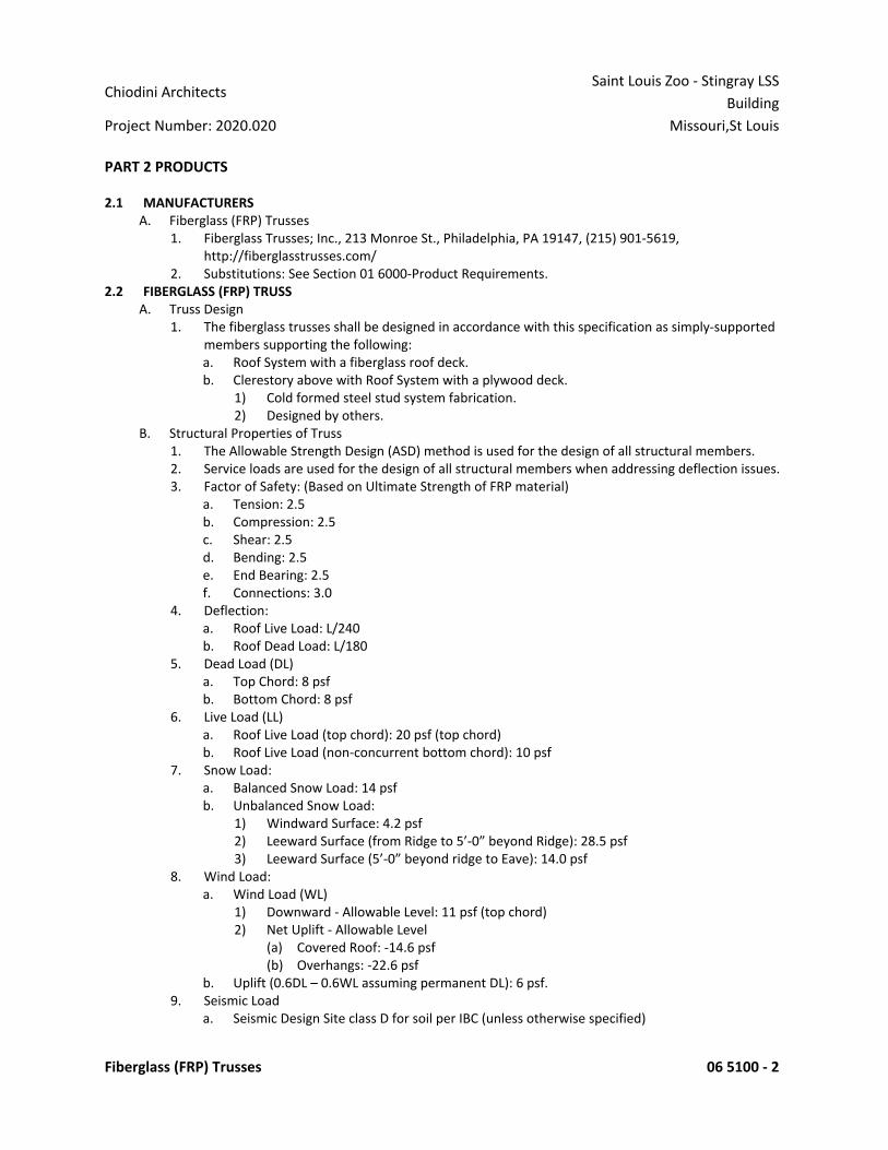
Chiodini ArchitectsSaint Louis Zoo - Stingray LSS
BuildingProject Number: 2020.020 Missouri,St Louis
Fiberglass (FRP) Trusses 06 5100 - 2
PART 2 PRODUCTS
2.1 MANUFACTURERSA. Fiberglass (FRP) Trusses
1. Fiberglass Trusses; Inc., 213 Monroe St., Philadelphia, PA 19147, (215) 901-5619,http://fiberglasstrusses.com/
2. Substitutions: See Section 01 6000-Product Requirements .2.2 FIBERGLASS (FRP) TRUSS
A. Truss Design1. The fiberglass trusses shall be designed in accordance with this specification as simply-supported
members supporting the following:a. Roof System with a fiberglass roof deck.b. Clerestory above with Roof System with a plywood deck.
1) Cold formed steel stud system fabrication.2) Designed by others.
B. Structural Properties of Truss1. The Allowable Strength Design (ASD) method is used for the design of all structural members.2. Service loads are used for the design of all structural members when addressing deflection issues.3. Factor of Safety: (Based on Ultimate Strength of FRP material)
a. Tension: 2.5b. Compression: 2.5c. Shear: 2.5d. Bending: 2.5e. End Bearing: 2.5f. Connections: 3.0
4. Deflection:a. Roof Live Load: L/240b. Roof Dead Load: L/180
5. Dead Load (DL)a. Top Chord: 8 psfb. Bottom Chord: 8 psf
6. Live Load (LL)a. Roof Live Load (top chord): 20 psf (top chord)b. Roof Live Load (non-concurrent bottom chord): 10 psf
7. Snow Load:a. Balanced Snow Load: 14 psfb. Unbalanced Snow Load:
1) Windward Surface: 4.2 psf2) Leeward Surface (from Ridge to 5’-0” beyond Ridge): 28.5 psf3) Leeward Surface (5’-0” beyond ridge to Eave): 14.0 psf
8. Wind Load:a. Wind Load (WL)
1) Downward - Allowable Level: 11 psf (top chord)2) Net Uplift - Allowable Level
(a) Covered Roof: -14.6 psf(b) Overhangs: -22.6 psf
b. Uplift (0.6DL – 0.6WL assuming permanent DL): 6 psf.9. Seismic Load
a. Seismic Design Site class D for soil per IBC (unless otherwise specified)
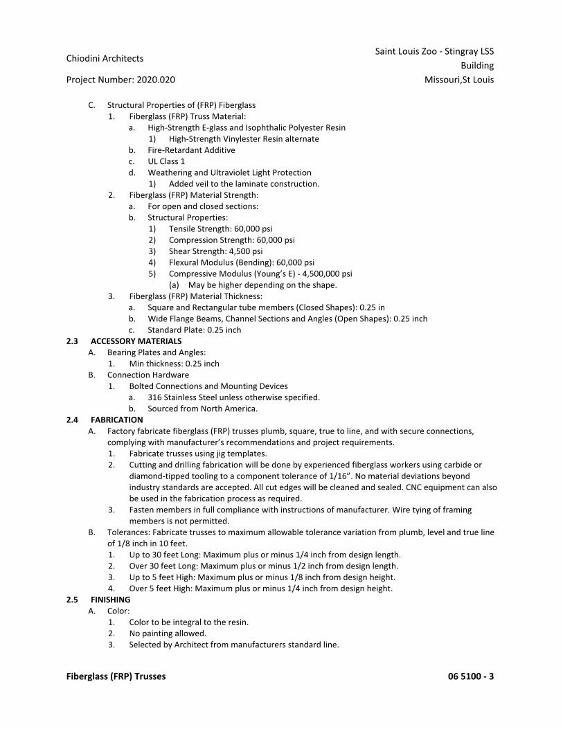
Chiodini ArchitectsSaint Louis Zoo - Stingray LSS
BuildingProject Number: 2020.020 Missouri,St Louis
Fiberglass (FRP) Trusses 06 5100 - 3
C. Structural Properties of (FRP) Fiberglass1. Fiberglass (FRP) Truss Material:
a. High-Strength E-glass and Isophthalic Polyester Resin1) High-Strength Vinylester Resin alternate
b. Fire-Retardant Additivec. UL Class 1d. Weathering and Ultraviolet Light Protection
1) Added veil to the laminate construction.2. Fiberglass (FRP) Material Strength:
a. For open and closed sections:b. Structural Properties:
1) Tensile Strength: 60,000 psi2) Compression Strength: 60,000 psi3) Shear Strength: 4,500 psi4) Flexural Modulus (Bending): 60,000 psi5) Compressive Modulus (Young’s E) - 4,500,000 psi
(a) May be higher depending on the shape.3. Fiberglass (FRP) Material Thickness:
a. Square and Rectangular tube members (Closed Shapes): 0.25 inb. Wide Flange Beams, Channel Sections and Angles (Open Shapes): 0.25 inchc. Standard Plate: 0.25 inch
2.3 ACCESSORY MATERIALSA. Bearing Plates and Angles:
1. Min thickness: 0.25 inchB. Connection Hardware
1. Bolted Connections and Mounting Devicesa. 316 Stainless Steel unless otherwise specified.b. Sourced from North America.
2.4 FABRICATIONA. Factory fabricate fiberglass (FRP) trusses plumb, square, true to line, and with secure connections,
complying with manufacturer’s recommendations and project requirements.1. Fabricate trusses using jig templates.2. Cutting and drilling fabrication will be done by experienced fiberglass workers using carbide or
diamond-tipped tooling to a component tolerance of 1/16”. No material deviations beyondindustry standards are accepted. All cut edges will be cleaned and sealed. CNC equipment can alsobe used in the fabrication process as required.
3. Fasten members in full compliance with instructions of manufacturer. Wire tying of framingmembers is not permitted.
B. Tolerances: Fabricate trusses to maximum allowable tolerance variation from plumb, level and true lineof 1/8 inch in 10 feet .1. Up to 30 feet Long: Maximum plus or minus 1/4 inch from design length.2. Over 30 feet Long: Maximum plus or minus 1/2 inch from design length.3. Up to 5 feet High: Maximum plus or minus 1/8 inch from design height.4. Over 5 feet High: Maximum plus or minus 1/4 inch from design height.
2.5 FINISHINGA. Color:
1. Color to be integral to the resin.2. No painting allowed.3. Selected by Architect from manufacturers standard line.
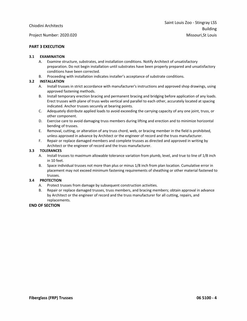
Chiodini ArchitectsSaint Louis Zoo - Stingray LSS
BuildingProject Number: 2020.020 Missouri,St Louis
Fiberglass (FRP) Trusses 06 5100 - 4
PART 3 EXECUTION
3.1 EXAMINATIONA. Examine structure, substrates, and installation conditions. Notify Architect of unsatisfactory
preparation. Do not begin installation until substrates have been properly prepared and unsatisfactoryconditions have been corrected.
B. Proceeding with installation indicates installer’s acceptance of substrate conditions.3.2 INSTALLATION
A. Install trusses in strict accordance with manufacturer's instructions and approved shop drawings, usingapproved fastening methods.
B. Install temporary erection bracing and permanent bracing and bridging before application of any loads.Erect trusses with plane of truss webs vertical and parallel to each other, accurately located at spacingindicated. Anchor trusses securely at bearing points.
C. Adequately distribute applied loads to avoid exceeding the carrying capacity of any one joint, truss, orother component.
D. Exercise care to avoid damaging truss members during lifting and erection and to minimize horizontalbending of trusses.
E. Removal, cutting, or alteration of any truss chord, web, or bracing member in the field is prohibited,unless approved in advance by Architect or the engineer of record and the truss manufacturer.
F. Repair or replace damaged members and complete trusses as directed and approved in writing byArchitect or the engineer of record and the truss manufacturer.
3.3 TOLERANCESA. Install trusses to maximum allowable tolerance variation from plumb, level, and true to line of 1/8 inch
in 10 feet .B. Space individual trusses not more than plus or minus 1/8 inch from plan location. Cumulative error in
placement may not exceed minimum fastening requirements of sheathing or other material fastened totrusses.
3.4 PROTECTIONA. Protect trusses from damage by subsequent construction activities.B. Repair or replace damaged trusses, truss members, and bracing members; obtain approval in advance
by Architect or the engineer of record and the truss manufacturer for all cutting, repairs, andreplacements.
END OF SECTION
Chiodini ArchitectsSaint Louis Zoo - Stingray LSS
BuildingProject Number: 2020.020 Missouri,St Louis
Fiberglass (FRP) Decking 06 5113 - 1
SECTION 06 5113 - FIBERGLASS (FRP) DECKINGPART 1 GENERAL
1.1 SECTION INCLUDESA. Roof deck.B. Bearing plates and angles.C. Fasteners.D. Closures and Sealant.
1.2 REFERENCE STANDARDSA. ASTM 2583 – Indentation Hardness of Plastics.B. ASTM D696 – Coefficient of Linear Thermal Expansion of Plastics.C. ASTM D790 – Standard Test Method for Flexural Properties of Unreinforced and Reinforced Plastics and
Electrical Insulating Materials.D. ASTM E72 – Strength of Panels for Building Construction.E. ASTM E84 – Standard Test Method for Surface Burning Characteristics of Building Materials.
1.3 SUBMITTALSA. See Section 01 3000 - Administrative Requirements, for submittals procedures.B. Product Data: Provide deck profile characteristics, dimensions, structural properties, and finishes.C. Shop Drawings: Indicate deck plan, support locations, projections, openings, reinforcement, pertinent
details, and accessories.D. Certificates: Certify that products furnished meet or exceed specified requirements.E. Submit manufacturer's installation instructions.F. Designer's Qualification Statement.G. Fabricator's Qualification Statement: Provide documentation showing steel fabricator is accredited
under IAS AC172.1.4 QUALITY ASSURANCE
A. Fabricator Qualifications: A qualified fiberglass (FRP) fabricator specializing in performing the work ofthis Section with minimum 5 years of experience.
B. Installer Qualifications: Company specializing in performing the work of this Section with minimum 5years of experience.
1.5 DELIVERY, STORAGE, AND HANDLINGA. Cut plastic wrap to encourage ventilation.B. Separate sheets and store deck on dry wood sleepers; slope for positive drainage.
1.6 WARRANTYA. See Section 01 7800-Closeout Submittals, for additional warranty requirements.B. Provide 15-year manufacturer warranty covering design, materials and workmanship, including
degradation or failure due to chemical contact.PART 2 PRODUCTS
2.1 MANUFACTURERSA. Fiberglass (FRP) Deck:
1. Enduro Composites, Tuff Span; www.endurocomposites.com2. Substitutions: See Section 01 6000 - Product Requirements.
2.2 FIBERGLASS (FRP) DECKA. All Deck Types: Select and design metal deck in accordance with local codes.
1. Calculated to structural working stress design and structural properties specified.2. Factor of safety:
a. Live Load (LL): 2.5b. Wind Load, Uplift: 1.88

Chiodini ArchitectsSaint Louis Zoo - Stingray LSS
BuildingProject Number: 2020.020 Missouri,St Louis
Fiberglass (FRP) Decking 06 5113 - 2
3. Max Vertical Deflection of Floor Deck: 1/360.4. Max Vertical Deflection of Roof Deck: 1/240.
B. Roof Deck: Non-Composite type, fluted fiberglass sheet:1. Fiberglass Sheet:
a. High-Strength Polyester Resin1) High-Strength Vinylester Resin Alternate
b. Fire-Retardant Additive.c. UL Class 1.d. FM Global Approval.
2. Structural Properties:a. Tensile Strength: 42,000 psi.b. Flexural Strength: 55,000 psi.c. Flexural Modulus (Bending): 2,400,000 psi.d. Wind Uplift: Class 1-90e. Span Design: Double.
3. Nominal Height: 2 inches.4. Profile: Fluted.5. Formed Sheet Width: 24-36 inch.6. Side Joints: Lapped, mechanically fastened .7. End Joints: Lapped, mechanically fastened .
2.3 ACCESSORY MATERIALSA. Bearing Plates and Angles:
1. Min thickness: 0.25 inchB. Fasteners:
1. 316 Stainless steela. Self-tappingb. Sourced from North America
C. Deck Closure:1. Closures:
a. EPDMb. Match Panel Profile.
2. Sealants:a. Dimension: 3/32” x 1/2"b. Non-Shrink, Non- Hardening Butyl Tape
2.4 FABRICATIONA. Glass Fiber:
1. 48% - 50% of the Weight.2. Continuous and Straight.3. Bidirectional Alignment.
2.5 FINISHINGA. Color:
1. Integral to resin.2. No painting allowed.3. Selected by Architect from manufacturers standard line.
PART 3 EXECUTION
3.1 EXAMINATIONA. Examine structure, substrates, and installation conditions. Notify Architect of unsatisfactory
preparation. Do not begin installation until substrates have been properly prepared and unsatisfactory
Chiodini ArchitectsSaint Louis Zoo - Stingray LSS
BuildingProject Number: 2020.020 Missouri,St Louis
Fiberglass (FRP) Decking 06 5113 - 3
conditions have been corrected.B. Proceeding with installation indicates installer’s acceptance of substrate conditions.
3.2 INSTALLATIONA. Materials shall be installed in accordance with Manufacturer’s Installation Instructions and Drawings.B. Mechanical Fastening:
1. Stainless steel Self-Tapping screws: pilot holes must be drilled through the panel and support.2. Stainless steel Self-Drilling screws: Pilot holes are not required for self-drilling stainless steel
screws having a carbon steel point and are suitable for thickness of .158-.55” (4-14mm).3. Stainless Steel Grommets: Pilot holes must be drilled through panels and flashing.
C. Verify side lap spacing with FM Global installation requirements.END OF SECTION
Chiodini ArchitectsSaint Louis Zoo - Stingray LSS
BuildingProject Number: 2020.020 Missouri,St Louis
Fiberglass Reinforced Paneling 06 8316 - 1
SECTION 06 8316 - FIBERGLASS REINFORCED PANELINGPART 1 GENERAL
1.1 SECTION INCLUDESA. Fiberglass reinforced plastic panels.B. Trim.
1.2 REFERENCE STANDARDSA. 9 CFR 416.2 - Regulatory Requirements Under the Federal Meat Inspection Act and the Poultry Products
Inspection Act, Part 416-Sanitation current edition.B. ASTM D256 - Standard Test Methods for Determining the Izod Pendulum Impact Resistance of Plastics
2010 (Reapproved 2018).C. ASTM D2583 - Standard Test Method for Indentation Hardness of Rigid Plastics by Means of Barcol
Impressor 2013a.D. ASTM D3273 - Standard Test Method for Resistance to Growth of Mold on the Surface of Interior
Coatings in an Environmental Chamber 2016.E. ASTM D5319 - Standard Specification for Glass-Fiber Reinforced Polyester Wall and Ceiling Panels 2017.F. ASTM E84 - Standard Test Method for Surface Burning Characteristics of Building Materials 2021.G. ISO 846 - Plastics - Evaluation of the action of microorganisms 2019.H. ISO 2812-1 - Paints and varnishes -- Determination of resistance to liquids -- Part 1: Immersion in liquids
other than water 2017.1.3 SUBMITTALS
A. See Section 01 3000 - Administrative Requirements, for submittal procedures.B. Product Data: Provide data on specified products, describing physical and performance characteristics;
including sizes, patterns and colors available; and installation instructions.C. Samples: Submit two samples 12" by 12" inch in size illustrating material and surface design of panels.D. Maintenance Materials: Furnish the following for Owner's use in maintenance of project.
1. See Section 01 6000 - Product Requirements, for additional provisions.1.4 DELIVERY, STORAGE, AND HANDLING
A. Store panels flat, indoors, on a clean, dry surface. Remove packaging and allow panels to acclimate toroom temperature for 48 hours prior to installation.
PART 2 PRODUCTS
2.1 MANUFACTURERSA. Fiberglass Reinforced Plastic Panels:
1. Crane Composites, Inc ; Glasbord : www.cranecomposites.com/#sle.2. Marlite, Inc ; Standard FRP : www.marlite.com/#sle.3. Panolam Industries International, Inc; Panolam FRP: www.panolam.com/#sle.4. Substitutions: See Section 01 6000 - Product Requirements.
2.2 PANEL SYSTEMSA. Wall Panels:
1. Panel Size: Manufacturer standard to minizine joints.2. Panel Thickness: 0.09 inch .3. Surface Design: Embossed.4. Color: White.5. Attachment Method: Adhesive only, with trim and sealant in joints .
2.3 MATERIALSA. Panels: Fiberglass reinforced plastic (FRP), complying with ASTM D5319.
1. Surface Burning Characteristics: Maximum flame spread index of 25 and smoke developed indexof 450; when system tested in accordance with ASTM E84.

Chiodini ArchitectsSaint Louis Zoo - Stingray LSS
BuildingProject Number: 2020.020 Missouri,St Louis
Fiberglass Reinforced Paneling 06 8316 - 2
2. Surface Burning Characteristics: Class A; when system tested in accordance with ASTM E84.3. Mold Resistance: Score of 10, when tested in accordance with ASTM D3273.4. Scratch Resistance: Barcol hardness score greater than 35, when tested in accordance with ASTM
D2583.5. Impact Strength: Greater than 6 ft lb force per inch, when tested in accordance with ASTM D256.6. Sanitation and Cleanability: Comply with 9 CFR 416.2.7. Chemical Cleanability: Excellent chemical resistance to common cleaners and detergents when
tested in accordance with ISO 2812-1.8. Biological Resistance: Rating of 0, when tested in accordance with ISO 846.
B. Trim: Vinyl; color coordinating with panel.C. Adhesive: Type recommended by panel manufacturer.D. Sealant: Type recommended by panel manufacturer ; color matching panel .
PART 3 EXECUTION
3.1 EXAMINATIONA. Verify existing conditions and substrate flatness before starting work.B. Verify that substrate conditions are ready to receive the work of this section.
3.2 INSTALLATION - WALLSA. Install panels in accordance with manufacturer's instructions.B. Cut panels with carbide tipped saw blades.C. Apply adhesive to the back side of the panel using trowel as recommended by adhesive manufacturer.D. Apply panels to wall with seams plumb and pattern aligned with adjoining panels.E. Install panels with manufacturer's recommended gap for panel field and corner joints.F. Place trim on panel before fastening edges, as required.G. Fill channels in trim with sealant before attaching to panel.H. Install trim with adhesive, as required.I. Seal gaps at floor, ceiling, and between panels with applicable sealant to prevent moisture intrusion.J. Remove excess sealant after paneling is installed and prior to curing.
END OF SECTION

Chiodini ArchitectsSaint Louis Zoo - Stingray LSS
BuildingProject Number: 2020.020 Missouri,St Louis
Thermal Insulation 07 2100 - 1
SECTION 07 2100 - THERMAL INSULATIONPART 1 GENERAL
1.1 SECTION INCLUDESA. Board insulation and integral vapor retarder at over roof deck .B. Board insulation at perimeter foundation wall and underside of floor slabs.
1.2 REFERENCE STANDARDSA. ASTM C578 - Standard Specification for Rigid, Cellular Polystyrene Thermal Insulation 2019.B. ASTM C1289 - Standard Specification for Faced Rigid Cellular Polyisocyanurate Thermal Insulation Board
2020.C. ASTM E84 - Standard Test Method for Surface Burning Characteristics of Building Materials 2021.D. NFPA 285 - Standard Fire Test Method for Evaluation of Fire Propagation Characteristics of Exterior
Non-Load-Bearing Wall Assemblies Containing Combustible Components 2019.1.3 SUBMITTALS
A. See Section 01 3000 - Administrative Requirements for submittal procedures.B. ABAA Field Quality Control Submittals: Submit third-party reports of testing and inspection required by
ABAA QAP.C. ABAA Manufacturer Qualification: Submit documentation of current evaluation of proposed
manufacturer and materials.D. ABAA Installer Qualification: Submit documentation of current contractor accreditation and current
installer certification. Keep copies of contractor accreditation and installer certification on project siteduring and after installation. Present on-site documentation upon request.
1.4 QUALITY ASSURANCEA. Air Barrier Association of America (ABAA) Quality Assurance Program (QAP); www.airbarrier.org/#sle:
1. Installer Qualification: Use accredited contractors, certified installers, evaluated materials, andthird-party field quality control audit.
2. Manufacturer Qualification: Use evaluated materials from a single manufacturer regularlyengaged in air barrier material manufacture. Use secondary materials approved in writing byprimary material manufacturer.
PART 2 PRODUCTS
2.1 APPLICATIONSA. Insulation Under Concrete Slabs: Extruded polystyrene (XPS) board.B. Insulation at Perimeter of Foundation: Extruded polystyrene (XPS) board.C. Insulation Over Roof Deck: Polyisocyanurate board.
2.2 FOAM BOARD INSULATION MATERIALSA. Extruded Polystyrene (XPS) Board Insulation: Complies with ASTM C578 with either natural skin or cut
cell surfaces.1. Type and Compressive Resistance: Type IV, 25 psi (173 kPa), minimum.2. Flame Spread Index (FSI): Class A - 0 to 25, when tested in accordance with ASTM E84.3. Smoke Developed Index (SDI): 450 or less, when tested in accordance with ASTM E84.4. Type and Thermal Resistance, R-value: Type IV, 5.0 (0.88), minimum, per 1 inch thickness at 75
degrees F mean temperature.B. Composite Polyisocyanurate (ISO) Board Insulation Faced with Plywood: Rigid cellular foam, complying
with ASTM C1289.1. Flame Spread Index (FSI): Class A - 0 to 25, when tested in accordance with ASTM E84.2. Smoke Developed Index (SDI): 450 or less, when tested in accordance with ASTM E84.3. Complies with fire resistance requirements indicated on drawings as part of an exterior non-load-
bearing exterior wall assembly when tested in accordance with NFPA 285.

Chiodini ArchitectsSaint Louis Zoo - Stingray LSS
BuildingProject Number: 2020.020 Missouri,St Louis
Thermal Insulation 07 2100 - 2
4. Board Size: 48 inch by 96 inch.5. Plywood Thickness: 1/2 inch .6. Insulation Board Thickness: per drawings.
a. If available product thickness does not meet required thickness, provide additional layers ofpolyisocyanurate board to achieve required thickness.
7. Board Edges: Square.8. Products:
a. Atlas Roofing Corporation; ACFoam Nail Base Roof Insulation Panels: www.atlasroofing.com/#sle.
b. Hunter Panels; Xci Ply: www.hunterpanels.com/#sle.c. Substitutions: See Section 01 6000 - Product Requirements.
2.3 ACCESSORIESA. Sheet Vapor Retarder: Self-adhering membrane applied direct application over structural roof deck
1. Water Vapor Permeability (ASTM E96): 0.03 Perms2. Thickness: 15 mil, 0.015 inches3. Width: 42.5 inches4. Elongation (ASTM D1970): 330%5. UL (ASTM E108): Class A6. FM Approval: Standard Class 4470, Class 17. Low Temperature Flexibility (ASTM D1970): -20 degrees Celsius8. Products:
a. VapAir Seal MD by Carlisle Syntec Systemsb. Substitutions: See Section 01 6000-Product Requirements.
B. Sheet Water and Vapor Retarder: Self-adhering membrane applied over composite polyisocyanurateboard insulation plywood face.1. Water Vapor Permeability (ASTM E96): 0.05 Perms2. Thickness: 40 mil, 0.04 inches3. Width: As required4. Elongation (ASTM D412): 250%5. UL (ASTM E108): Class A6. Low Temperature Flexibility (ASTM D1970): -20 degrees Celsius7. Products:8.
a. Ice and Water Shield by GCP Applied Technologiesb. Substitutions: See Section 01 6000-Product Requirements.
PART 3 EXECUTION
3.1 EXAMINATIONA. Verify that substrate, adjacent materials, and insulation materials are dry and that substrates are ready
to receive insulation.B. Verify substrate surfaces are flat, free of honeycomb, fins, irregularities, or materials or substances that
may impede adhesive bond.3.2 BOARD INSTALLATION AT FOUNDATION PERIMETER
A. Adhere a 6 inches wide strip of polyethylene sheet over construction, control, and expansion joints withdouble beads of adhesive each side of joint.1. Tape seal joints.2. Extend sheet full height of joint.
B. Install boards horizontally on foundation perimeter.C. Cut and fit insulation tightly to protrusions or interruptions to the insulation plane.

Chiodini ArchitectsSaint Louis Zoo - Stingray LSS
BuildingProject Number: 2020.020 Missouri,St Louis
Thermal Insulation 07 2100 - 3
3.3 BOARD INSTALLATION UNDER CONCRETE SLABSA. Place insulation under slabs on grade after base for slab has been compacted.B. Cut and fit insulation tightly to protrusions or interruptions to the insulation plane.C. Prevent insulation from being displaced or damaged while placing vapor retarder and placing slab.
3.4 FIELD QUALITY CONTROLA. See Section 01 4000 - Quality Requirements for additional requirements.B. Coordination of Air Barrier Association of America (ABAA) Tests and Inspections:
1. Provide testing and inspection required by ABAA Quality Assurance Program (QAP).2. Notify ABAA in writing of schedule for air barrier work, and allow adequate time for testing and
inspection.3. Cooperate with ABAA testing agency.4. Allow access to air barrier work areas and staging.5. Do not cover air barrier work until tested, inspected, and accepted.
3.5 PROTECTIONA. Do not permit installed insulation to be damaged prior to its concealment.
END OF SECTION
Chiodini ArchitectsSaint Louis Zoo - Stingray LSS
BuildingProject Number: 2020.020 Missouri,St Louis
Weather Barriers 07 2500 - 1
SECTION 07 2500 - WEATHER BARRIERSPART 1 GENERAL
1.1 SECTION INCLUDESA. Water-Resistive Barrier: Under exterior wall cladding, over sheathing or other substrate; not air tight or
vapor retardant.B. Vapor Retarders: Materials to make interior partitions and decks water vapor resistant and air tight.
1.2 DEFINITIONSA. Weather Barrier: Assemblies that form either water-resistive barriers, air barriers, or vapor retarders.B. Air Barrier: Air tight barrier made of material that is relatively air impermeable but water vapor
permeable, both to the degree specified, with sealed seams and with sealed joints to adjacent surfaces. Note: For the purposes of this specification, vapor impermeable air barriers are classified as vaporretarders.
C. Vapor Retarder: Air tight barrier made of material that is relatively water vapor impermeable, to thedegree specified, with sealed seams and with sealed joints to adjacent surfaces.1. Water Vapor Permeance: For purposes of conversion, 57.2 ng/(Pa s sq m) = 1 perm.
D. Water-Resistive Barrier: Water-shedding barrier made of material that is moisture resistant, to thedegree specified, intended to be installed to shed water without sealed seams.
1.3 REFERENCE STANDARDSA. ASTM D1970/D1970M - Standard Specification for Self-Adhering Polymer Modified Bituminous Sheet
Materials Used as Steep Roofing Underlayment for Ice Dam Protection 2020.B. ASTM E2178 - Standard Test Method for Determining Air Leakage Rate and Calculation of Air
Permeance of Building Materials 2021.1.4 SUBMITTALS
A. See Section 01 3000 - Administrative Requirements, for submittal procedures.B. Product Data: Provide data on material characteristics.C. Shop Drawings: Provide drawings of special joint conditions.D. ABAA Field Quality Control Submittals: Submit third-party reports of testing and inspection required by
ABAA QAP.E. Manufacturer's Installation Instructions: Indicate preparation.F. ABAA Manufacturer Qualification: Submit documentation of current evaluation of proposed
manufacturer and materials.G. ABAA Installer Qualification: Submit documentation of current contractor accreditation and current
installer certification; keep copies of each contractor accreditation and installer certification on siteduring and after installation, and present on-site documentation upon request.
1.5 QUALITY ASSURANCEA. Air Barrier Association of America (ABAA) Quality Assurance Program (QAP); www.airbarrier.org/#sle:
1. Installer Qualification: Use accredited contractor, certified installers, evaluated materials, andthird-party field quality control audit.
2. Manufacturer Qualification: Use evaluated materials from a single manufacturer regularlyengaged in air barrier material manufacture, and use secondary materials approved in writing byprimary material manufacturer.
1.6 MOCK-UPA. Install air barrier, vapor retarder, and water-resistive barrier materials in mock-up specified by
Architect.1.7 FIELD CONDITIONS
A. Maintain temperature and humidity recommended by the materials manufacturers before, during andafter installation.
PART 2 PRODUCTS
Chiodini ArchitectsSaint Louis Zoo - Stingray LSS
BuildingProject Number: 2020.020 Missouri,St Louis
Weather Barriers 07 2500 - 2
2.1 WEATHER BARRIER ASSEMBLIESA. Interior Weather Barrier and Vapor Retarder:
1. On the indicated side of partitions and/or decking, use vapor retarder sheet.2.2 AIR BARRIER MATERIALS (AIR AND VAPOR BARRIER)
A. Air and Vapor Barrier Sheet, Self-Adhered:1. Air Permeance: 0.004 cfm/sq ft, maximum, when tested in accordance with ASTM E2178.2. Water Vapor Permeance: 0.02 perms, maximum, when tested in accordance with ASTM
E96/E96M, Procedure B.3. Water Penetration Resistance Around Nails: Pass, when tested in accordance with ASTM
D1970/D1970M (modified).4. Complies with NFPA 285 wall assembly requirements.5. Seam and Perimeter Tape: As recommended by sheet manufacturer.6. Manufacturers:
a. Carlisle Coatings and Waterproofing, Inc; Fire Resist 705FR-A: www.carlisleccw.com/#sle.b. GCP Applied Technologies; Perm-A-Barrier NPS: www.gcpat.com/#sle.c. Polyguard Products, Inc; Airlok Sheet 200 BU/NP Air and Moisture Barrier:
www.polyguardproducts.com/#sle.d. Protecto Wrap Company; Protecto Universal Primer-Free Membrane:
www.protectowrap.com/#sle.e. Tremco Commercial Sealants & Waterproofing; ExoAir 110AT:
www.tremcosealants.com/#sle.f. Substitutions: See Section 01 6000 - Product Requirements.
2.3 ACCESSORIESA. Sealants, Tapes, and Accessories for Sealing Weather Barrier and Sealing Weather Barrier to Adjacent
Substrates: As specified or as recommended by weather barrier manufacturer.B. Flexible Flashing: Self-adhesive sheet flashing complying with ASTM D1970/D1970M, except slip
resistance requirement is waived if not installed on a roof.C. Sill Plate Sealer: Closed-cell foam tape with rubberized adhesive membrane; bridges gap between
foundation structure and sill plate or skirt board.1. Manufacturers:
a. Protecto Wrap Company; Triple Guard Energy Sill Sealer: www.protectowrap.com/#sle.b. Substitutions: See Section 01 6000 - Product Requirements.
PART 3 EXECUTION
3.1 EXAMINATIONA. Verify that surfaces and conditions are ready to accept the work of this section.
3.2 PREPARATIONA. Remove projections, protruding fasteners, and loose or foreign matter that might interfere with proper
installation.B. Clean and prime substrate surfaces to receive adhesives in accordance with manufacturer's
instructions.3.3 INSTALLATION
A. Install materials in accordance with manufacturer's instructions.B. Water-Resistive Barriers: Install continuous barrier over surfaces indicated, with sheets lapped to shed
water but with seams not sealed.C. Vapor Retarders: Install continuous air tight barrier over surfaces indicated, with sealed seams and with
sealed joints to adjacent surfaces.D. Apply sealants and adhesives within recommended application temperature ranges. Consult
manufacturer if temperature is out of this range.
Chiodini ArchitectsSaint Louis Zoo - Stingray LSS
BuildingProject Number: 2020.020 Missouri,St Louis
Weather Barriers 07 2500 - 3
E. Self-Adhered Sheets:1. Prepare substrate in manner recommended by sheet manufacturer; fill and tape joints in
substrate and between dissimilar materials.2. Lap sheets shingle-fashion to shed water and seal laps air tight.3. Once sheets are in place, press firmly into substrate with resilient hand roller; ensure that laps are
firmly adhered with no gaps or fishmouths.4. Use same material, or other material approved by sheet manufacturer for the purpose, to seal to
adjacent construction and as flashing.5. At wide joints, provide extra flexible membrane allowing joint movement.
3.4 FIELD QUALITY CONTROLA. See Section 01 4000 - Quality Requirements, for additional requirements.
3.5 PROTECTIONA. Do not leave materials exposed to weather longer than recommended by manufacturer.B. Do not leave paper- or felt-based barriers exposed to weather for longer than one week.
END OF SECTION
Chiodini ArchitectsSaint Louis Zoo - Stingray LSS
BuildingProject Number: 2020.020 Missouri,St Louis
Metal Roof Panels 07 4113 - 1
SECTION 07 4113 - METAL ROOF PANELSPART 1 GENERAL
1.1 SECTION INCLUDESA. Architectural roofing system of preformed steel panels.
1.2 RELATED REQUIREMENTSA. Section 06 1000 - Rough Carpentry: Roof sheathing.
1.3 REFERENCE STANDARDSA. AAMA 2605 - Voluntary Specification, Performance Requirements and Test Procedures for Superior
Performing Organic Coatings on Aluminum Extrusions and Panels (with Coil Coating Appendix) 2017a.B. ASTM A792/A792M - Standard Specification for Steel Sheet, 55% Aluminum-Zinc Alloy-Coated by the
Hot-Dip Process 2021.C. ASTM D1970/D1970M - Standard Specification for Self-Adhering Polymer Modified Bituminous Sheet
Materials Used as Steep Roofing Underlayment for Ice Dam Protection 2020.D. ASTM E1592 - Standard Test Method for Structural Performance of Sheet Metal Roof and Siding
Systems by Uniform Static Air Pressure Difference 2005 (Reapproved 2017).E. ASTM E1646 - Standard Test Method for Water Penetration of Exterior Metal Roof Panel Systems by
Uniform Static Air Pressure Difference 2011 (Reapproved 2018).F. ASTM E1680 - Standard Test Method for Rate of Air Leakage Through Exterior Metal Roof Panel Systems
2016.G. IAS AC472 - Accreditation Criteria for Inspection Programs for Manufacturers of Metal Building Systems
2018.H. UL 580 - Standard for Tests for Uplift Resistance of Roof Assemblies Current Edition, Including All
Revisions.1.4 SUBMITTALS
A. See Section 01 3000 - Administrative Requirements for submittal procedures.B. Product Data: Manufacturer's data sheets on each product to be used, including:
1. Summary of test results, indicating compliance with specified requirements.2. Storage and handling requirements and recommendations.3. Installation methods.4. Specimen warranty.
C. Shop Drawings: Include layouts of roof panels, details of edge and penetration conditions, spacing andtype of connections, flashings, underlayments, and special conditions.1. Show work to be field-fabricated or field-assembled.2. Include structural analysis signed and sealed by qualified structural engineer, indicating
compliance of roofing system to specified loading conditions.D. Verification Samples: For each roofing system specified, submit samples of minimum size 12 inches
square, representing actual roofing metal, thickness, profile, color, and texture.1. Include typical panel joint in sample.2. Include typical fastening detail.
E. Manufacturer's qualification statement.1. Provide documentation that indicates manufacturer is accredited under IAS AC472.
F. Installer's qualification statement.G. Test Reports: Indicate compliance of metal roofing system to specified requirements.H. Warranty: Submit specified manufacturer's warranty and ensure that forms have been completed in
Owner's name and are registered with manufacturer.1.5 QUALITY ASSURANCE
A. Manufacturer Qualifications: Company specializing in manufacturing products specified in this section,with not less than three years of documented experience.
Chiodini ArchitectsSaint Louis Zoo - Stingray LSS
BuildingProject Number: 2020.020 Missouri,St Louis
Metal Roof Panels 07 4113 - 2
1. Accredited by IAS in accordance with IAS AC472.B. Installer Qualifications: Company specializing in performing work of the type specified and with at least
three years of documented experience.1.6 DELIVERY, STORAGE, AND HANDLING
A. Provide strippable plastic protection on prefinished roofing panels for removal after installation.B. Store roofing panels on project site as recommended by manufacturer to minimize damage to panels
prior to installation.1.7 WARRANTY
A. See Section 01 7800 - Closeout Submittals for additional warranty requirements.B. Finish Warranty: Provide manufacturer's special warranty covering failure of factory-applied exterior
finish on metal roof panels and agreeing to repair or replace panels that show evidence of finishdegradation, including significant fading, chalking, cracking, or peeling within specified warranty periodof five years from Date of Substantial Completion.
C. Waterproofing Warranty: Provide manufacturer's warranty for weathertightness of roofing system,including agreement to repair or replace roofing that fails to keep out water within specified warrantyperiod of five years from Date of Substantial Completion.
PART 2 PRODUCTS
2.1 MANUFACTURERSA. Basis of Design:
1. Architectural Metal Roof Panels: Meridian with Minor Ribs manufactured by McElroy Metals, Inc .a. Substitutions: See Section 01 6000-Product Requirements.
2.2 PERFORMANCE REQUIREMENTSA. Metal Roof Panels: Provide complete roofing assemblies, including roof panels, clips, fasteners,
connectors, and miscellaneous accessories, tested for compliance with the following minimumstandards:1. Overall: Complete weathertight system tested and approved in accordance with ASTM E1592.2. Wind Uplift: Class 90 wind uplift resistance of UL 580.3. Air Infiltration: Maximum 0.06 cfm/sq ft at air pressure differential of 6.24 lbf/sq ft, when tested
according to ASTM E1680.4. Water Penetration: No water penetration when tested according to procedures and
recommended test pressures of ASTM E1646. Perform test immediately following air infiltrationtest.
5. Thermal Movement: Design system to accommodate without deformation anticipated thermalmovement over ambient temperature range of 100 degrees F.
2.3 ARCHITECTURAL METAL ROOF PANELSA. Architectural Metal Roof Panels: Provide complete engineered system complying with specified
requirements and capable of remaining weathertight while withstanding anticipated movement ofsubstrate and thermally induced movement of roofing system.
B. Architectural Metal Panels: Factory-formed panels with factory-applied finish.1. Steel Panels:
a. Aluminum-zinc alloy-coated steel complying with ASTM A792/A792M; minimum AZ50coating.
b. Steel Thickness: Minimum 24 gauge, 0.024 inch.2. Profile: Standing seam, with minimum 1.0 inch seam height; concealed fastener system
[__________] .3. Texture: Smooth, with intermediate ribs for added stiffness .4. Length: Full length of roof slope, without lapped horizontal joints.5. Width: Maximum panel coverage of 16 inches .
Chiodini ArchitectsSaint Louis Zoo - Stingray LSS
BuildingProject Number: 2020.020 Missouri,St Louis
Metal Roof Panels 07 4113 - 3
2.4 ATTACHMENT SYSTEMA. Concealed System: Provide manufacturer's standard stainless steel concealed anchor clips designed for
specific roofing system and engineered to meet performance requirements, including anticipatedthermal movement.
2.5 FABRICATIONA. Panels: Provide factory fabricated panels with applied finish and accessory items, using manufacturer's
standard processes as required to achieve specified appearance and performance requirements.2.6 FINISHES
A. Fluoropolymer Coil Coating System: Manufacturer's standard multi-coat aluminum coil coating systemcomplying with AAMA 2605, including at least 70 percent polyvinylidene fluoride (PVDF) resin, and atleast 80 percent of coil coated aluminum surfaces having minimum total dry film thickness (DFT) of 0.9mil, 0.0009 inch; color and gloss to match sample.
2.7 ACCESSORIESA. Miscellaneous Sheet Metal Items: Provide trim, moldings, closure strips, caps, and equipment curbs of
the same material, thickness, and finish as used for the roofing panels. Items completely concealedafter installation may optionally be made of stainless steel.
B. Rib and Ridge Closures: Provide prefabricated, close-fitting components of steel with corrosionresistant finish or combination steel and closed-cell foam.
C. Sealants:1. Exposed Sealant: Elastomeric; silicone, polyurethane, or silyl-terminated polyether/polyurethane.2. Concealed Sealant: Non-curing butyl sealant or tape sealant.3. Seam Sealant: Factory-applied, non-skinning, non-drying type.
D. Underlayment: Synthetic non-asphaltic sheet, intended by manufacturer for mechanically fastenedroofing underlayment without sealed seams.1. Self Sealability: Passing nail sealability test specified in ASTM D1970/D1970M.2. Low Temperature Flexibility: Passing test specified in ASTM D1970/D1970M.3. Fasteners: As specified by manufacturer and building code qualification report or approval.
PART 3 EXECUTION
3.1 EXAMINATIONA. Do not begin installation of preformed metal roof panels until substrates have been properly prepared.B. If substrate preparation is the responsibility of another installer, notify Architect of unsatisfactory
preparation before proceeding.3.2 PREPARATION
A. Broom clean wood sheathing prior to installation of roofing system.B. Coordinate roofing work with provisions for roof drainage, flashing, trim, penetrations, and other
adjoining work to assure that the completed roof will be free of leaks.C. Coordinate installation of waterproof membrane over roof sheathing; see Section 06 1000.D. Remove protective film from surface of roof panels immediately prior to installation. Strip film carefully,
to avoid damage to prefinished surfaces.E. Separate dissimilar metals by applying a bituminous coating, self-adhering rubberized asphalt sheet, or
other permanent method approved by roof panel manufacturer.F. Where metal will be in contact with wood or other absorbent material subject to wetting, seal joints
with sealing compound and apply one coat of heavy-bodied bituminous paint.3.3 INSTALLATION
A. Overall: Install roofing system in accordance with approved shop drawings and panel manufacturer'sinstructions and recommendations, as applicable to specific project conditions. Anchor all componentsof roofing system securely in place while allowing for thermal and structural movement.
Chiodini ArchitectsSaint Louis Zoo - Stingray LSS
BuildingProject Number: 2020.020 Missouri,St Louis
Metal Roof Panels 07 4113 - 4
1. Install roofing system with concealed clips and fasteners, except as otherwise recommended bymanufacturer for specific circumstances.
2. Install roofing system with exposed fasteners prefinished to match panels.3. Minimize field cutting of panels. Where field cutting is absolutely required, use methods that will
not distort panel profiles. Use of torches for field cutting is absolutely prohibited.B. Accessories: Install all components required for a complete roofing assembly, including flashings, trim,
moldings, closure strips, preformed crickets, caps, equipment curbs, rib closures, ridge closures, andsimilar roof accessory items .
C. Roof Panels: Install panels in strict accordance with manufacturer's instructions, minimizing transversejoints except at junction with penetrations.1. Install sealant or sealant tape, as recommended by panel manufacturer, at end laps and side
joints.3.4 CLEANING
A. Clean exposed sheet metal work at completion of installation. Remove grease and oil films, excess jointsealer, handling marks, and debris from installation, leaving the work clean and unmarked, free fromdents, creases, waves, scratch marks, or other damage to the finish.
3.5 PROTECTIONA. Do not permit storage of materials or roof traffic on installed roof panels. Provide temporary walkways
or planks as necessary to avoid damage to completed work. Protect roofing until completion of project.B. Touch-up, repair, or replace damaged roof panels or accessories before Date of Substantial Completion.
END OF SECTION

Chiodini ArchitectsSaint Louis Zoo - Stingray LSS
BuildingProject Number: 2020.020 Missouri,St Louis
Metal Wall Panels 07 4213 - 1
SECTION 07 4213 - METAL WALL PANELSPART 1 GENERAL
1.1 SECTION INCLUDESA. Manufactured metal panels for exterior wall panels, interior liner panels, soffit panels, and subgirt
framing assembly , with insulation, related flashings, and accessory components .1.2 RELATED REQUIREMENTS
A. Section 05 4000 - Cold-Formed Metal Framing: Wall panel substrate.1.3 REFERENCE STANDARDS
A. AAMA 2605 - Voluntary Specification, Performance Requirements and Test Procedures for SuperiorPerforming Organic Coatings on Aluminum Extrusions and Panels (with Coil Coating Appendix) 2017a.
B. ASTM A792/A792M - Standard Specification for Steel Sheet, 55% Aluminum-Zinc Alloy-Coated by theHot-Dip Process 2021.
C. NFPA 285 - Standard Fire Test Method for Evaluation of Fire Propagation Characteristics of ExteriorNon-Load-Bearing Wall Assemblies Containing Combustible Components 2019.
1.4 SUBMITTALSA. See Section 01 3000 - Administrative Requirements for submittal procedures.B. Product Data - Wall System: Manufacturer's data sheets on each product to be used, including:
1. Physical characteristics of components shown on shop drawings.2. Storage and handling requirements and recommendations.3. Installation instructions and recommendations.
C. Shop Drawings: Indicate dimensions, layout, joints, construction details, support clips, [_____], andmethods of anchorage.
D. Samples: Submit two samples of wall panel and soffit panel, 12 inches by 12 inches in size illustratingfinish color, sheen, and texture.
E. Test Reports: Submit test report verifying compliance with NFPA 285 for previously-tested exterior wallassembly.
F. Manufacturer's Qualification Statement.G. Installer's Qualification Statement.H. Warranty Documentation for Installation of Building Rainscreen Assembly: Submit installer warranty
and ensure that forms have been completed in Owner's name and registered with installer.1.5 QUALITY ASSURANCE
A. Manufacturer Qualifications: Company specializing in manufacturing the products specified in thissection with minimum three years of documented experience.
B. Installer Qualifications: Company specializing in installing products of the type specified in this sectionwith minimum three years of documented experience.
1.6 DELIVERY, STORAGE, AND HANDLINGA. Protect panels from accelerated weathering by removing or venting sheet plastic shipping wrap.B. Store prefinished material off the ground and protected from weather; prevent twisting, bending, or
abrasion; provide ventilation; slope metal sheets to ensure proper drainage.C. Prevent contact with materials that may cause discoloration or staining of products.
1.7 WARRANTYA. See Section 01 7800 - Closeout Submittals for additional warranty requirements.B. Correct defective work within a five year period after Date of Substantial Completion for degradation of
panel finish, including color fading caused by exposure to weather.C. Correct defective work within a five year period after Date of Substantial Completion, including defects
in water tightness and integrity of seals for metal wall panels.D. Installation Warranty for Building Rainscreen Assembly: Installer of exterior rainscreen assembly
(including air/vapor barrier and attachments, framing, and exterior panels) to provide 10-year warranty

Chiodini ArchitectsSaint Louis Zoo - Stingray LSS
BuildingProject Number: 2020.020 Missouri,St Louis
Metal Wall Panels 07 4213 - 2
that includes coverage for defective materials and/or workmanship. This warranty will also clearlyinclude materials, labor, necessary activity to access these areas, and removal of any materials to effectrepairs and restore to watertight conditions. www.edacontractors.com/#sle
PART 2 PRODUCTS
2.1 MANUFACTURERSA. Basis of Design:
1. Exterior Metal Wall Panels: 7.2 Panel manufactured by MetlSpan.2. Interior Insulated Metal Wall Panels: CF Santa Fe manufactured by MetlSpan.3. Interior Insulated Metal Wall Panels (Alternate): FRP Clean Seam manufactured by MetlSpan.4. Exterior Metal Soffit Panels: Artisan manufactured by MetlSpan.
B. Other Acceptable Manufacturers :1. Substitutions: See Section01 6000-Product Requirements .
2.2 MANUFACTURED METAL PANELSA. Wall Panel System: Factory fabricated prefinished metal panel system, site assembled.
1. Provide exterior wall panels, soffit panels, and interior insulated wall panels .2. Design and size components to support assembly dead loads, and to withstand live loads caused
by positive and negative wind pressure acting normal to plane of wall.3. Design Pressure: In accordance with applicable codes.4. Fire Performance: Tested in accordance with, and complying with acceptance criteria of NFPA
285.5. Maximum Allowable Deflection of Panel: L/180 for length(L) of span.6. Movement: Accommodate movement within system without damage to components or
deterioration of seals, movement between system and perimeter components when subject toseasonal temperature cycling; dynamic loading and release of loads; and deflection of structuralsupport framing.
7. Drainage: Provide positive drainage to exterior for moisture entering or condensation occurringwithin panel system.
8. Fabrication: Formed true to shape, accurate in size, square, and free from distortion or defects;pieces of longest practical lengths.
9. Exterior Metal Wall Panel Corners: Manufacturer Standard.10. Interior Insulated Metal Wall Panel Corners: Factory-fabricated in one continuous piece with
minimum 12 inch returns.B. Exterior Wall Panels:
1. Profile: Horizontal ; style as indicated .2. Material: Precoated steel sheet, 22 gauge, 0.0299 inch minimum thickness.3. Panel Width: 36 inches.4. Length: Provide lengths to eliminate vertical side seems.5. Color: As selected by Architect from manufacturer's Standard and Premium line.
C. Interior Insulated Wall Panels:1. Profile: Horizontal ; style as indicated .2. Side Seams: Interlocking, sealed with continuous bead of sealant.3. Face Material: Precoated steel sheet, 24 gauge, 0.0239 inch minimum thickness.4. Back Material: Precoated steel sheet, 26 gauge, 0.0179 inch minimum thickness.5. Panel Width: 42 inch.6. Panel Width (alternate): 36 inch, if 42 inch is unaavailable.7. Panel Thickness: 2.5 inch.8. Panel Thickness (alternate): 3 inch, if 2.5 inch is unavailable.9. Length: Provide lengths to eliminate vertical side seems.
Chiodini ArchitectsSaint Louis Zoo - Stingray LSS
BuildingProject Number: 2020.020 Missouri,St Louis
Metal Wall Panels 07 4213 - 3
10. Color: White.11. Color (alternate): Manufactuers Standard FRP
D. Soffit Panels:1. Profile: Style as indicated, with venting provided.2. Material: Precoated steel sheet, 22 gauge, 0.0299 inch minimum thickness.3. Color: As selected by Architect from manufacturer's Standard and Premium line.
E. Trim: Same material, thickness and finish as exterior sheets; brake formed to required profiles.F. Anchors: Stainless steel .
2.3 MATERIALSA. Precoated Steel Sheet: Aluminum-zinc alloy-coated steel sheet, ASTM A792/A792M, Commercial Steel
(CS)) or Forming Steel (FS), with AZ50/AZM150 coating; continuous-coil-coated on exposed surfaceswith specified finish coating and on panel back with specified panel back coating.
2.4 FINISHESA. Exterior Metal Panel:
1. Exposed Surface Finish: Panel manufacturer's standard polyvinylidene fluoride (PVDF) coating, topcoat over epoxy primer.
2. Panel Backside Finish: Panel manufacturer's standard polyvinylidene fluoride (PVDF) coating, topcoat over epoxy primer.
B. Interior Insulated Metal Panel:1. Exposed Surface Finish: Panel manufacturer's standard polyvinylidene fluoride (PVDF) coating, top
coat over epoxy primer.2. Panel Backside Finish: Panel manufacturer's standard siliconized polyester coating.
C. Fluoropolymer Coil Coating System: Manufacturer's standard multi-coat aluminum coil coating systemcomplying with AAMA 2605, including at least 70 percent polyvinylidene fluoride (PVDF) resin, and atleast 80 percent of coil coated aluminum surfaces having minimum total dry film thickness (DFT) of 0.9mil, 0.0009 inch; color and gloss to match sample.
2.5 ACCESSORIESA. Gaskets: Manufacturer's standard type suitable for use with system, permanently resilient; ultraviolet
and ozone resistant.B. Concealed Sealants: Non-curing butyl sealant or tape sealant.C. Exposed Sealant: Elastomeric; silicone, polyurethane, or silyl-terminated polyether/polyurethane.D. Exterior Fasteners: Manufacturer's standard type to suit application; with soft neoprene washers, steel,
hot dip galvanized. Fastener cap same color as exterior panel.1. Metal-to-Metal Fasteners: Self-drilling, self-tapping screws.
E. Interior Fasteners: Manufacturer's standard type to suit application; Stainless Steel1. Metal-to-Metal Fasteners: Self-drilling, self-tapping screws.
F. Field Touch-up Paint: As recommended by panel manufacturer.PART 3 EXECUTION
3.1 EXAMINATIONA. Verify that building framing members are ready to receive panels.B. Verify that water-resistive barrier has been installed over substrate completely and correctly.
3.2 INSTALLATIONA. Install panels on walls and soffits in accordance with manufacturer's instructions.B. Fasten panels to structural supports; aligned, level, and plumb.C. Seal and place gaskets to prevent weather penetration. Maintain neat appearance.
3.3 TOLERANCESA. Maximum Offset From True Alignment Between Adjacent Members Butting or In Line: 1/16 inch.B. Maximum Variation from Plane or Location Indicated on Drawings: 1/4 inch.
Chiodini ArchitectsSaint Louis Zoo - Stingray LSS
BuildingProject Number: 2020.020 Missouri,St Louis
Metal Wall Panels 07 4213 - 4
3.4 CLEANINGA. Remove site cuttings from finish surfaces.B. Remove protective material from wall panel surfaces.C. See Section 01 7419 - Construction Waste Management and Disposal for additional requirements.D. Clean and wash prefinished surfaces with mild soap and water; rinse with clean water.
END OF SECTION
Chiodini ArchitectsSaint Louis Zoo - Stingray LSS
BuildingProject Number: 2020.020 Missouri,St Louis
Sheet Metal Flashing and Trim 07 6200 - 1
SECTION 07 6200 - SHEET METAL FLASHING AND TRIMPART 1 GENERAL
1.1 SECTION INCLUDESA. Fabricated sheet metal items, including flashings, gutters, downspouts, and other items indicated in
Schedule .B. Sealants for joints within sheet metal fabrications.C. Precast concrete splash pads.
1.2 REFERENCE STANDARDSA. AAMA 2605 - Voluntary Specification, Performance Requirements and Test Procedures for Superior
Performing Organic Coatings on Aluminum Extrusions and Panels (with Coil Coating Appendix) 2017a.B. ASTM C920 - Standard Specification for Elastomeric Joint Sealants 2018.C. ASTM D4586/D4586M - Standard Specification for Asphalt Roof Cement, Asbestos-Free 2007
(Reapproved 2018).D. CDA A4050 - Copper in Architecture - Handbook current edition.E. SMACNA (ASMM) - Architectural Sheet Metal Manual 2012.
1.3 ADMINISTRATIVE REQUIREMENTSA. Preinstallation Meeting: Convene [____] before starting work of this section.
1.4 SUBMITTALSA. See Section 01 3000 - Administrative Requirements, for submittal procedures.B. Shop Drawings: Indicate material profile, jointing pattern, jointing details, fastening methods, flashings,
terminations, and installation details.C. Samples: Submit two samples 12" by 12" inch in size illustrating metal finish color.
1.5 QUALITY ASSURANCEA. Perform work in accordance with SMACNA (ASMM) and CDA A4050 requirements and standard details,
except as otherwise indicated.B. Maintain one copy of each document on site.C. Fabricator and Installer Qualifications: Company specializing in sheet metal work with [____] years of
documented experience.1.6 DELIVERY, STORAGE, AND HANDLING
A. Stack material to prevent twisting, bending, and abrasion, and to provide ventilation. Slope metalsheets to ensure drainage.
B. Prevent contact with materials that could cause discoloration or staining.PART 2 PRODUCTS
2.1 MANUFACTURERSA. Sheet Metal Flashing and Trim Manufacturers:
1. MBCI; www.mbci.com2. Substitutions: See Section 01 6000 - Product Requirements.
2.2 SHEET MATERIALSA. Pre-Finished Galvanized Steel: ASTM A653/A653M, with G90/Z275 zinc coating; minimum 24 gage,
(0.0239) inch thick base metal, shop pre-coated with PVDF coating.1. PVDF (Polyvinylidene Fluoride) Coating: Superior Performance Organic Finish, AAMA 2605;
multiple coat, thermally cured fluoropolymer finish system.2. Color: Match Existing.
2.3 FABRICATIONA. Form sections true to shape, accurate in size, square, and free from distortion or defects.B. Form pieces in longest possible lengths.C. Hem exposed edges on underside 1/2 inch; miter and seam corners.

Chiodini ArchitectsSaint Louis Zoo - Stingray LSS
BuildingProject Number: 2020.020 Missouri,St Louis
Sheet Metal Flashing and Trim 07 6200 - 2
D. Form material with flat lock seams, except where otherwise indicated; at moving joints, use sealedlapped, bayonet-type or interlocking hooked seams.
E. Fabricate corners from one piece with minimum 18 inch long legs; seam for rigidity, seal with sealant.F. Fabricate snow guards in accordance with SMACNA (ASMM) Plate [_____].
2.4 GUTTER AND DOWNSPOUT FABRICATIONA. Gutters: Square profile to match existing in size and shape.B. Downspouts: Rectangular profile to match existing in size and shape.C. Accessories: Profiled to suit gutters and downspouts.
1. Anchorage Devices: In accordance with SMACNA (ASMM) requirements.2. Gutter Supports: Brackets.3. Downspout Supports: Brackets.
D. Splash Pads: Precast concrete type.E. Seal metal joints.
2.5 ACCESSORIESA. Fasteners: Stainless steel , with soft neoprene washers .B. Primer: Zinc chromate type.C. Concealed Sealants: Non-curing butyl sealant.D. Exposed Sealants: ASTM C920; elastomeric sealant, with minimum movement capability as
recommended by manufacturer for substrates to be sealed; color to match adjacent material.E. Plastic Cement: ASTM D4586/D4586M, Type I.
PART 3 EXECUTION
3.1 EXAMINATIONA. Verify roof openings, curbs, pipes, sleeves, ducts, and vents through roof are solidly set, reglets in place,
and nailing strips located.B. Verify roofing termination and base flashings are in place, sealed, and secure.
3.2 PREPARATIONA. Install starter and edge strips, and cleats before starting installation.B. Back paint concealed metal surfaces with protective backing paint to a minimum dry film thickness of
15 mil.3.3 INSTALLATION
A. Secure flashings in place using concealed fasteners, and use exposed fasteners only where permitted..B. Apply plastic cement compound between metal flashings and felt flashings.C. Fit flashings tight in place; make corners square, surfaces true and straight in planes, and lines accurate
to profiles.D. Secure gutters and downspouts in place with stainless steel fasteners.E. Slope gutters 1/4 inch per 10 feet, minimum.F. Connect downspouts to storm sewer system, and seal connection watertight.G. Set Splash Pads under dowspounts onto grade.
3.4 FIELD QUALITY CONTROLA. See Section 01 4000 - Quality Requirements, for field inspection requirements.B. Inspection will involve surveillance of work during installation to ascertain compliance with specified
requirements.3.5 SCHEDULE
A. Fascia:B. Gutters and Downspouts:C. Roofing Penetration Flashings, for Pipes, Structural Steel, and Equipment Supports:D. Snow Guards:
END OF SECTION
Chiodini ArchitectsSaint Louis Zoo - Stingray LSS
BuildingProject Number: 2020.020 Missouri,St Louis
Joint Sealants 07 9200 - 1
SECTION 07 9200 - JOINT SEALANTSPART 1 GENERAL
1.1 SECTION INCLUDESA. Nonsag gunnable joint sealants.B. Self-leveling pourable joint sealants.C. Joint backings and accessories.
1.2 REFERENCE STANDARDSA. ASTM C1193 - Standard Guide for Use of Joint Sealants 2016.B. ASTM C1521 - Standard Practice for Evaluating Adhesion of Installed Weatherproofing Sealant Joints
2019 (Reapproved 2020).1.3 SUBMITTALS
A. See Section 01 3000 - Administrative Requirements, for submittal procedures.B. Product Data for Sealants: Submit manufacturer's technical data sheets for each product to be used,
that includes the following.1. Physical characteristics, including movement capability, VOC content, hardness, cure time, and
color availability.2. List of backing materials approved for use with the specific product.3. Substrates that product is known to satisfactorily adhere to and with which it is compatible.4. Substrates the product should not be used on.5. Substrates for which use of primer is required.6. Installation instructions, including precautions, limitations, and recommended backing materials
and tools.7. Sample product warranty.
C. Product Data for Accessory Products: Submit manufacturer's technical data sheet for each product tobe used, including physical characteristics, installation instructions, and recommended tools.
D. Color Cards for Selection: Where sealant color is not specified, submit manufacturer's color cardsshowing standard colors available for selection.
E. Preinstallation Field Adhesion Test Plan: Submit at least two weeks prior to start of installation.F. Field Quality Control Plan: Submit at least two weeks prior to start of installation.G. Preinstallation Field Adhesion Test Reports: Submit filled out Preinstallation Field Adhesion Test
Reports log within 10 days after completion of tests; include bagged test samples and photographicrecords.
H. Field Quality Control Log: Submit filled out log for each length or instance of sealant installed, within 10days after completion of inspections/tests; include bagged test samples and photographic records, ifany.
I. Manufacturer's Qualification Statement.J. Installer's Qualification Statement.
1.4 QUALITY ASSURANCEA. Maintain one copy of each referenced document covering installation requirements on site.B. Manufacturer Qualifications: Company specializing in manufacturing the products specified in this
section with minimum three years documented experience.C. Installer Qualifications: Company specializing in performing the work of this section and with at least
three years of documented experience.D. Testing Agency Qualifications: Independent firm specializing in performing testing and inspections of
the type specified in this section.E. Field Quality Control Plan:
1. Visual inspection of entire length of sealant joints.2. Non-destructive field adhesion testing of sealant joints, except interior acrylic latex sealants.
Chiodini ArchitectsSaint Louis Zoo - Stingray LSS
BuildingProject Number: 2020.020 Missouri,St Louis
Joint Sealants 07 9200 - 2
a. For each different sealant and substrate combination, allow for one test every 12 inches inthe first 10 linear feet of joint and one test every 24 inches thereafter.
b. If any failures occur in the first 10 linear feet, continue testing at 12 inches intervals at noextra cost to Owner.
3. Field testing to be performed by Contractor in the presence of Architect.F. Field Adhesion Test Procedures:
1. Allow sealants to fully cure as recommended by manufacturer before testing.2. Have a copy of the test method document available during tests.3. Record the type of failure that occurred, other information required by test method, and the
information required on the Field Quality Control Log.4. If any combination of sealant type and substrate does not show evidence of minimum adhesion or
shows cohesion failure before minimum adhesion, report results to Architect.G. Non-Destructive Field Adhesion Test: Test for adhesion in accordance with ASTM C1521, using
Nondestructive Spot Method.H. Field Adhesion Tests of Joints: Test for adhesion using most appropriate method in accordance with
ASTM C1521, or other applicable method as recommended by manufacturer.1.5 WARRANTY
A. See Section 01 7800 - Closeout Submittals, for additional warranty requirements.B. Correct defective work within a five year period after Date of Substantial Completion.C. Warranty: Include coverage for installed sealants and accessories that fail to achieve watertight seal ,
exhibit loss of adhesion or cohesion, or do not cure.PART 2 PRODUCTS
2.1 MANUFACTURERSA. Non-Sag Sealants: Permits application in joints on vertical surfaces without sagging or slumping.
1. Bostik Inc; [_____]: www.bostik-us.com/#sle.2. Dow Chemical Company; [_____]: consumer.dow.com/en-us/industry/ind-building-
construction.html/#sle.3. QUIKRETE Companies; [_____]: www.quikrete.com/#sle.4. Sherwin-Williams Company; [_____]: www.sherwin-williams.com/#sle.5. Sika Corporation; [_____]: www.usa-sika.com/#sle.6. Tremco Commercial Sealants & Waterproofing; [____]: www.tremcosealants.com/#sle.7. W.R. Meadows, Inc; [_____]: www.wrmeadows.com/#sle.8. Substitutions: See Section 01 6000 - Product Requirements.
B. Self-Leveling Sealants: Pourable or self-leveling sealant that has sufficient flow to form a smooth, levelsurface when applied in a horizontal joint.1. Bostik Inc; [_____]: www.bostik-us.com/#sle.2. Dow Chemical Company; [_____]: consumer.dow.com/en-us/industry/ind-building-
construction.html/#sle.3. QUIKRETE Companies; [_____]: www.quikrete.com/#sle.4. Sherwin-Williams Company; [_____]: www.sherwin-williams.com/#sle.5. Sika Corporation; [_____]: www.usa-sika.com/#sle.6. Tremco Commercial Sealants & Waterproofing; [____]: www.tremcosealants.com/#sle.7. W.R. Meadows, Inc; [_____]: www.wrmeadows.com/#sle.8. Substitutions: See Section 01 6000 - Product Requirements.
2.2 JOINT SEALANT APPLICATIONSA. Scope:
1. Exterior Joints: Seal open joints, whether or not the joint is indicated on drawings, unlessspecifically indicated not to be sealed. Exterior joints to be sealed include, but are not limited to,
Chiodini ArchitectsSaint Louis Zoo - Stingray LSS
BuildingProject Number: 2020.020 Missouri,St Louis
Joint Sealants 07 9200 - 3
the following items.a. Joints between door, window, and other frames and adjacent construction.
2. Interior Joints: Do not seal interior joints unless specifically indicated to be sealed. Interior jointsto be sealed include, but are not limited to, the following items.a. Joints between door, window, and other frames and adjacent construction.
3. Do not seal the following types of joints.a. Joints indicated to be treated with manufactured expansion joint cover or some other type of
sealing device.b. Joints where sealant is specified to be provided by manufacturer of product to be sealed.c. Joints where installation of sealant is specified in another section.
2.3 JOINT SEALANTS - GENERALA. Colors: As indicated on drawings.B. Colors: Selected by architect from manufacturers full line.
2.4 ACCESSORIESA. Backer Rod: Cylindrical cellular foam rod with surface that sealant will not adhere to, compatible with
specific sealant used, and recommended by backing and sealant manufacturers for specific application.1. Closed Cell and Bi-Cellular: 25 to 33 percent larger in diameter than joint width.2. Manufacturers:
a. ADFAST Corporation; ADSEAL BR-2600 (Backer Rod): www.adfastcorp.com/#sle.b. Nomaco, Inc; [______]: www.nomaco.com/#sle.c. Substitutions: See Section 01 6000 - Product Requirements.
B. Backing Tape: Self-adhesive polyethylene tape with surface that sealant will not adhere to andrecommended by tape and sealant manufacturers for specific application.
PART 3 EXECUTION
3.1 EXAMINATIONA. Verify that joints are ready to receive work.B. Verify that backing materials are compatible with sealants.C. Verify that backer rods are of the correct size.
3.2 PREPARATIONA. Remove loose materials and foreign matter that could impair adhesion of sealant.B. Clean joints, and prime as necessary, in accordance with manufacturer's instructions.C. Perform preparation in accordance with manufacturer's instructions and ASTM C1193.D. Mask elements and surfaces adjacent to joints from damage and disfigurement due to sealant work; be
aware that sealant drips and smears may not be completely removable.E. Concrete Floor Joints That Will Be Exposed in Completed Work: Test joint filler in inconspicuous area to
verify that it does not stain or discolor slab.3.3 INSTALLATION
A. Perform work in accordance with sealant manufacturer's requirements for preparation of surfaces andmaterial installation instructions.
B. Perform installation in accordance with ASTM C1193.C. Measure joint dimensions and size joint backers to achieve width-to-depth ratio, neck dimension, and
surface bond area as recommended by manufacturer, except where specific dimensions are indicated.D. Install bond breaker backing tape where backer rod cannot be used.E. Install sealant free of air pockets, foreign embedded matter, ridges, and sags, and without getting
sealant on adjacent surfaces.F. Do not install sealant when ambient temperature is outside manufacturer's recommended temperature
range, or will be outside that range during the entire curing period, unless manufacturer's approval isobtained and instructions are followed.

Chiodini ArchitectsSaint Louis Zoo - Stingray LSS
BuildingProject Number: 2020.020 Missouri,St Louis
Joint Sealants 07 9200 - 4
G. Nonsag Sealants: Tool surface concave, unless otherwise indicated; remove masking tape immediatelyafter tooling sealant surface.
3.4 FIELD QUALITY CONTROLA. Perform field quality control inspection/testing as specified in PART 1 under QUALITY ASSURANCE
article.B. Non-Destructive Adhesion Testing: If there are any failures in first 100 linear feet, notify Architect
immediately.C. Remove and replace failed portions of sealants using same materials and procedures as indicated for
original installation.3.5 POST-OCCUPANCY
A. Post-Occupancy Inspection: Perform visual inspection of entire length of project sealant joints at a timethat joints have opened to their greatest width; i.e. at low temperature in thermal cycle. Report failuresimmediately and repair.
END OF SECTION
Chiodini ArchitectsSaint Louis Zoo - Stingray LSS
BuildingProject Number: 2020.020 Missouri,St Louis
Hollow Metal Doors and Frames 08 1113 - 1
SECTION 08 1113 - HOLLOW METAL DOORS AND FRAMESPART 1 GENERAL
1.1 SECTION INCLUDESA. Non-fire-rated hollow metal doors and frames.B. Thermally insulated hollow metal doors with frames.C. Accessories, including glazing .
1.2 RELATED REQUIREMENTSA. Section 08 7100 - Door Hardware.B. Section 08 8000 - Glazing: Glass for doors and borrowed lites.
1.3 ABBREVIATIONS AND ACRONYMSA. ANSI: American National Standards Institute.B. HMMA: Hollow Metal Manufacturers Association.C. NAAMM: National Association of Architectural Metal Manufacturers.D. SDI: Steel Door Institute.E. UL: Underwriters Laboratories.
1.4 REFERENCE STANDARDSA. ADA Standards - Americans with Disabilities Act (ADA) Standards for Accessible Design 2010.B. ANSI/SDI A250.3 - Test Procedure and Acceptance Criteria for Factory Applied Finish Coatings for Steel
Doors and Frames 2007 (Reaffirmed 2011).C. ANSI/SDI A250.4 - Test Procedure and Acceptance Criteria for Physical Endurance for Steel Doors,
Frames and Frame Anchors 2011.D. ANSI/SDI A250.8 - Specifications for Standard Steel Doors and Frames (SDI-100) 2017.E. ANSI/SDI A250.10 - Test Procedure and Acceptance Criteria for Prime Painted Steel Surfaces for Steel
Doors and Frames 2011.F. ASTM A653/A653M - Standard Specification for Steel Sheet, Zinc-Coated (Galvanized) or Zinc-Iron Alloy-
Coated (Galvannealed) by the Hot-Dip Process 2020.G. ASTM A1008/A1008M - Standard Specification for Steel, Sheet, Cold-Rolled, Carbon, Structural, High-
Strength Low-Alloy, High-Strength Low-Alloy with Improved Formability, Required Hardness, SolutionHardened, and Bake Hardenable 2020.
H. ASTM A1011/A1011M - Standard Specification for Steel, Sheet and Strip, Hot-Rolled, Carbon, Structural,High-Strength Low-Alloy, High-Strength Low-Alloy with Improved Formability, and Ultra-High Strength2018a.
I. BHMA A156.115 - American National Standard for Hardware Preparation in Steel Doors and SteelFrames 2016.
J. ICC A117.1 - Accessible and Usable Buildings and Facilities 2017.K. NAAMM HMMA 830 - Hardware Selection for Hollow Metal Doors and Frames 2002.L. NAAMM HMMA 831 - Hardware Locations for Hollow Metal Doors and Frames 2011.M. NAAMM HMMA 840 - Guide Specifications For Receipt, Storage and Installation of Hollow Metal Doors
and Frames 2007.N. NAAMM HMMA 861 - Guide Specifications for Commercial Hollow Metal Doors and Frames 2014.O. SDI 117 - Manufacturing Tolerances for Standard Steel Doors and Frames 2013.
1.5 SUBMITTALSA. See Section 01 3000 - Administrative Requirements, for submittal procedures.B. Product Data: Materials and details of design and construction, hardware locations, reinforcement type
and locations, anchorage and fastening methods, and finishes; and one copy of referencedstandards/guidelines.
C. Shop Drawings: Details of each opening, showing elevations, glazing, frame profiles, and any indicatedfinish requirements.
Chiodini ArchitectsSaint Louis Zoo - Stingray LSS
BuildingProject Number: 2020.020 Missouri,St Louis
Hollow Metal Doors and Frames 08 1113 - 2
1. Indicate product components, including hardware reinforcement locations and preparations,accessories, finish colors, patterns, and textures.
2. Indicate wall conditions, door and frame elevations, sections, materials, gages, finishes, locationof door hardware by dimension, and details of openings.
D. Samples: Submit two samples of metal, 2 by 2 inches in size, showing factory finishes, colors, andsurface texture.
E. Manufacturer's Certificate: Certification that products meet or exceed specified requirements.1.6 QUALITY ASSURANCE
A. Manufacturer Qualifications: Company specializing in manufacturing products specified in this section,with not less than three years documented experience.
B. Manufacturer Qualifications: Provide hollow metal doors and frames from SDI Certified manufacturer: www.steeldoor.org/sdicertified.php/#sle.
C. Maintain at project site copies of reference standards relating to installation of products specified.1.7 DELIVERY, STORAGE, AND HANDLING
A. Comply with NAAMM HMMA 840 or ANSI/SDI A250.8 (SDI-100) in accordance with specifiedrequirements.
B. Protect with resilient packaging; avoid humidity build-up under coverings; prevent corrosion andadverse effects on factory applied painted finish.
PART 2 PRODUCTS
2.1 MANUFACTURERSA. Hollow Metal Doors and Frames:
1. Ceco Door, an Assa Abloy Group company; [_____]: www.assaabloydss.com/#sle.2. Curries, an Assa Abloy Group company; [_____]: www.assaabloydss.com/#sle.3. Republic Doors, an Allegion brand; [____]: www.republicdoor.com/#sle.4. Steelcraft, an Allegion brand; [____]: www.allegion.com/#sle.5. Substitutions: See Section 01 6000 - Product Requirements.
2.2 PERFORMANCE REQUIREMENTSA. Requirements for Hollow Metal Doors and Frames:
1. Steel Sheet: Comply with one or more of the following requirements; galvannealed steelcomplying with ASTM A653/A653M, cold-rolled steel complying with ASTM A1008/A1008M, orhot-rolled pickled and oiled (HRPO) steel complying with ASTM A1011/A1011M, commercial steel(CS) Type B, for each.
2. Accessibility: Comply with ICC A117.1 and ADA Standards.3. Exterior Door Top Closures: Flush end closure channel, with top and door faces aligned.4. Door Edge Profile: Manufacturers standard for application indicated.5. Typical Door Face Sheets: Flush.6. Glazed Lights: Non-removable stops on non-secure side; sizes and configurations as indicated on
drawings. Style: Manufacturers standard.7. Hardware Preparations, Selections and Locations: Comply with NAAMM HMMA 830 and NAAMM
HMMA 831 or BHMA A156.115 and ANSI/SDI A250.8 (SDI-100) in accordance with specifiedrequirements.
8. Zinc Coating for Typical Interior and/or Exterior Locations: Provide metal components zinc-coated(galvanized) and/or zinc-iron alloy-coated (galvannealed) by the hot-dip process in accordancewith ASTM A653/A653M, with manufacturer's standard coating thickness, unless noted otherwisefor specific hollow metal doors and frames.a. Based on SDI Standards: Provide at least A40/ZF120 (galvannealed) when necessary, coating
not required for typical interior door applications, and at least A60/ZF180 (galvannealed) forcorrosive locations.
Chiodini ArchitectsSaint Louis Zoo - Stingray LSS
BuildingProject Number: 2020.020 Missouri,St Louis
Hollow Metal Doors and Frames 08 1113 - 3
B. Combined Requirements: If a particular door and frame unit is indicated to comply with more than onetype of requirement, comply with the specified requirements for each type; for instance, an exteriordoor that is also indicated as being sound-rated must comply with the requirements specified forexterior doors and for sound-rated doors; where two requirements conflict, comply with the moststringent.
2.3 HOLLOW METAL DOORSA. Door Finish: Factory finished .B. Type - Exterior , Exterior Doors: Thermally insulated.
1. Based on SDI Standards: ANSI/SDI A250.8 (SDI-100).a. Level 2 - Heavy-duty .b. Physical Performance Level B, 500,000 cycles; in accordance with ANSI/SDI A250.4.c. Model 1 - Full Flush.d. Door Face Metal Thickness: 18 gage, 0.042 inch , minimum.e. Hinge Reinforcement: 7 gauge, 0.179 inch.f. Closer Reinforcement Channel: 14 gauge, 0.067 inch.g. Galvanizing: G90/Z275 galvanized coating; ASTM A653/A653M.
2. Door Core Material: Vertical steel stiffeners with fiberglass batts.3. Door Thickness: 1-3/4 inches, nominal.4. Weatherstripping: Refer to Section 08 7100.
2.4 HOLLOW METAL FRAMESA. Comply with standards and/or custom guidelines as indicated for corresponding door in accordance
with applicable door frame requirements.B. Frame Finish: Factory finished .C. Exterior Door Frames: Full profile/continuously welded type .
1. Galvanizing: Components hot-dipped G90/Z275 galvanized coating; ASTM A653/A653M.2. Frame Metal Thickness: 16 gage, 0.053 inch , minimum.3. Weatherstripping: Separate, see Section 08 7100.
2.5 FINISHESA. Primer: Rust-inhibiting, complying with ANSI/SDI A250.10, door manufacturer's standard.B. Factory Finish: Complying with ANSI/SDI A250.3, door manufacturer's Enamel Coating .
1. Color: As selected by Architect from manufacturer's full range.2.6 ACCESSORIES
A. Door Window Frames: Door window frames with glazing securely fastened within door opening.1. Manufacturers:Size: As indicated on drawings.
a. Cardinal Glass Industries: www.cardinalcorp.comb. Guardian Glass, LLC: www.guardianglass.comc. Pilkington North America Inc: www.pilkington.comd. Viracon, Apogee Enterprises, Inc: www.viracon.come. Substitutions: See Section 01 6000-Product Requirements.
2. Frame Material: 18 gage, 0.0478 inch, galvanized steel.3. Metal Finish: Finish to match door.4. Glazing: 5/8" inch thick, insulated glass unit, in compliance with requirements of authorities
having jurisdiction.a. Durability: Certified by an independent testing agency to comply with ASTM E2190.b. Coated Glass: Comply with requirements of ASTM C1376 for pyrolytic (hard-coat) or
magnetic sputter vapor deposition (soft-coat) type coatings on flat glass; coated vision glass,Kind CV; coated overhead glass, Kind CO; or coated spandrel glass, Kind CS.
c. Metal Edge Spacers: Aluminum , bent and soldered corners.1) Spacer Width: As required for specified insulating glass unit .

Chiodini ArchitectsSaint Louis Zoo - Stingray LSS
BuildingProject Number: 2020.020 Missouri,St Louis
Hollow Metal Doors and Frames 08 1113 - 4
2) Spacer Color: Aluminum or Black.d. Space between lites: filled with argon.e. Outboard Lite: Fully tempered float glass , 1/4 inch thick , minimum .
1) Tint: Clear .2) Coating: Low-E (passive type) , on #2 surface.
f. Inboard Lite: Fully tempered float glass, 1/4 inch thick , minimum .1) Tint: Clear .
B. Glazing: As specified in Section 08 8000, factory installed.C. Removable Stops: Formed sheet steel , shape as indicated on drawings, mitered corners ; prepared for
countersink style tamper proof screws .D. Astragals and Edges for Double Doors: Pairs of door astragals, and door edge sealing and protection
devices.1. Provide surface mounted astragal to cover or fill space for full door height between pair of doors
or door and adjacent jamb.2. Astragal Type: Split, two parts , and with automatic locking, cutouts for other door hardware, and
sealing gasket .3. Edge Type: Beveled edge4. Material: Aluminum .5. Metal Finish: Finish to match door.6. Provide 316 stainless steel fasteners.
E. Mechanical Fasteners for Concealed Metal-to-Metal Connections: Self-drilling, self-tapping, steel withelectroplated zinc finish.
F. Silencers: Resilient rubber, fitted into drilled hole; provide three on strike side of single door, three oncenter mullion of pairs, and two on head of pairs without center mullions.
G. Temporary Frame Spreaders: Provide for factory- or shop-assembled frames.PART 3 EXECUTION
3.1 EXAMINATIONA. Verify actual dimensions of openings by field measurements before door fabrication; show recorded
measurements on shop drawings.B. Do not begin installation until substrates have been properly prepared.C. Verify existing conditions before starting work.D. Verify that opening sizes and tolerances are acceptable.E. Verify that finished walls are in plane to ensure proper door alignment.
3.2 PREPARATIONA. Prepare surfaces using the methods recommended by the manufacturer for achieving the best result
for the substrate under the project conditions.B. Clean and prepare substrate in accordance with manufacturer's directions.C. Protect adjacent work and finish surfaces from damage during installation.
3.3 INSTALLATIONA. Install doors and frames in accordance with manufacturer's instructions and related requirements of
specified door and frame standards or custom guidelines indicated.B. Install exterior doors in accordance with ASTM E2112.C. Set units plumb, level, and true-to-line, without warping or racking doors, and with specified clearances;
anchor in place.D. Coordinate frame anchor placement with wall construction.
1. Note exterior wall construction: Concrete wall to 12" above finished floor, Steel stud constructionfrom 12" aff to door head.
E. Install door hardware as specified in Section 08 7100.
Chiodini ArchitectsSaint Louis Zoo - Stingray LSS
BuildingProject Number: 2020.020 Missouri,St Louis
Hollow Metal Doors and Frames 08 1113 - 5
F. Comply with glazing installation requirements of Section 08 8000.G. Touch up damaged factory finishes.
3.4 TOLERANCESA. Clearances Between Door and Frame: Comply with related requirements of specified frame standards
or custom guidelines indicated in accordance with SDI 117 or NAAMM HMMA 861.B. Maximum Diagonal Distortion: 1/16 inch measured with straight edge, corner to corner.
3.5 ADJUSTINGA. Lubricate, test, and adjust doors to operate easily, free from warp, twist or distortion, and to fit
watertight for entire perimeter.B. Adjust for smooth and balanced door movement.C. Adjust hardware for smooth and quiet operation.D. Adjust doors to fit snugly and close without sticking or binding.
3.6 CLEANINGA. Clean installed products in accordance with manufacturer’s instructions prior to owner’s acceptance.
3.7 PROTECTIONA. Protect installed products from damage until Date of Substantial Completion.
3.8 SCHEDULEA. Refer to Door and Frame Schedule on the drawings.
END OF SECTION
Chiodini ArchitectsSaint Louis Zoo - Stingray LSS
BuildingProject Number: 2020.020 Missouri,St Louis
Fiberglass Doors 08 1613 - 1
SECTION 08 1613 - FIBERGLASS DOORSPART 1 GENERAL
1.1 SECTION INCLUDESA. Fiberglass doors.B. Fiberglass door frames.C. Door hardware.D. Accessories including Glazing.
1.2 RELATED REQUIREMENTSA. Section 08 1213 - Hollow Metal Frames: Metal frames.
1.3 REFERENCE STANDARDSA. AAMA 1503 - Voluntary Test Method for Thermal Transmittance and Condensation Resistance of
Windows, Doors and Glazed Wall Sections 2009.B. ASTM D256 - Standard Test Methods for Determining the Izod Pendulum Impact Resistance of Plastics
2010 (Reapproved 2018).C. ASTM D570 - Standard Test Method for Water Absorption of Plastics 1998 (Reapproved 2018).D. ASTM D635 - Standard Test Method for Rate of Burning and/or Extent and Time of Burning of Plastics in
a Horizontal Position 2018.E. ASTM D638 - Standard Test Method for Tensile Properties of Plastics 2014.F. ASTM D790 - Standard Test Methods for Flexural Properties of Unreinforced and Reinforced Plastics and
Electrical Insulating Materials 2017.G. ASTM D2583 - Standard Test Method for Indentation Hardness of Rigid Plastics by Means of Barcol
Impressor 2013a.H. ASTM E84 - Standard Test Method for Surface Burning Characteristics of Building Materials 2021.I. ASTM E90 - Standard Test Method for Laboratory Measurement of Airborne Sound Transmission Loss of
Building Partitions and Elements 2009 (Reapproved 2016).J. ASTM E283 - Standard Test Method for Determining the Rate of Air Leakage Through Exterior Windows,
Curtain Walls, and Doors Under Specified Pressure Differences Across the Specimen 2004 (Reapproved2012).
K. ASTM E330/E330M - Standard Test Method for Structural Performance of Exterior Windows, Doors,Skylights and Curtain Walls by Uniform Static Air Pressure Difference 2014.
L. ASTM E331 - Standard Test Method for Water Penetration of Exterior Windows, Skylights, Doors, andCurtain Walls by Uniform Static Air Pressure Difference 2000 (Reapproved 2016).
M. ASTM E1996 - Standard Specification for Performance of Exterior Windows, Curtain Walls, Doors, andImpact Protective Systems Impacted by Windborne Debris in Hurricanes 2017.
N. ASTM E2112 - Standard Practice for Installation of Exterior Windows, Doors and Skylights 2019c.O. ICC (IBC) - International Building Code Most Recent Edition Adopted by Authority Having Jurisdiction,
Including All Applicable Amendments and Supplements.1.4 SUBMITTALS
A. See Section 01 3000 - Administrative Requirements, for submittal procedures.B. Product Data: Provide manufacturer's standard details, installation instructions, hardware and anchor
recommendations.C. Shop Drawings: Indicate layout and profiles; include assembly methods.
1. Indicate product components, including hardware reinforcement locations and preparations,accessories, finish colors, patterns, and textures.
2. Indicate wall conditions, door and frame elevations, sections, materials, gages, finishes, locationof door hardware by dimension, and details of openings.
D. Selection Samples: Submit two complete sets of color chips, illustrating manufacturer's availablefinishes, colors, and textures.
Chiodini ArchitectsSaint Louis Zoo - Stingray LSS
BuildingProject Number: 2020.020 Missouri,St Louis
Fiberglass Doors 08 1613 - 2
E. Verification Samples: Submit door surface samples for each finish specified, 10 inches by 10 inches insize, illustrating finishes, colors, and textures.
F. Door Corner Sample: Submit corner cross sections, 10 inches by 10 inches in size, illustratingconstruction, finish, color, and texture.
G. Manufacturer's Qualification Statement.H. Warranty: Submit manufacturer warranty and ensure that forms have been completed in Owner's
name and registered with manufacturer; include detailed terms of warranty.1.5 QUALITY ASSURANCE
A. Manufacturer Qualifications: Company specializing in manufacturing products of the type specified inthis section, with not less than three years of documented experience.
1.6 DELIVERY, STORAGE, AND HANDLINGA. Mark doors with location of installation, door type, color, and weight.B. Deliver materials in manufacturer’s original, unopened, undamaged containers with identification labels
intact.C. Deliver pre-assembled doors and frames with braces, spreaders, and packaging as required to prevent
damage.D. Store materials in original packaging, under cover, protected from exposure to harmful weather
conditions and from direct contact with water.1. Store at temperature and humidity conditions recommended by manufacturer.2. Do not use non-vented plastic or canvas shelters.3. Immediately remove wet wrappers.
E. Store in position recommended by manufacturer, elevated minimum 4 inches above grade, withminimum 1/4 inch space between doors.
1.7 FIELD CONDITIONSA. Do not install doors until structure is enclosed.B. Maintain temperature and humidity at manufacturer's recommended levels during and after
installation of doors.1.8 WARRANTY
A. See Section 01 7800 - Closeout Submittals, for additional warranty requirements.B. Provide five (5) year manufacturer warranty covering materials and workmanship , including
degradation or failure due to chemical contact.PART 2 PRODUCTS
2.1 MANUFACTURERSA. Molded Fiberglass Doors:
1. ChemPruf Door Company, Ltd; [_____]: www.chem-pruf.com/#sle.2. Tiger Door, LLC; [_____]: www.tigerdoor.com/#sle.3. Substitutions: See Section 01 6000 - Product Requirements.
2.2 DOOR AND FRAME ASSEMBLIESA. Door and Frame Assemblies: Factory-fabricated, prepared and machined for hardware.
1. Screw-Holding Capacity: Tested to 890 pounds, minimum.2. Surface Burning Characteristics: Flame spread index (FSI) of 0 to 25, Class A, and smoke
developed index (SDI) of 450 or less, when tested in accordance with ASTM E84.3. Flammability: Self-extinguishing when tested in accordance with ASTM D635.4. Chemical Resistance: Resist degradation due to exposure to tap water and distilled water.
a. Ocean salt spray.5. Sizes: As indicated on drawings.6. Clearance Between Door and Frame: 1/8 inch, maximum.7. Clearance Between Meeting Stiles of Pairs of Doors: 1/8 inch, maximum.
Chiodini ArchitectsSaint Louis Zoo - Stingray LSS
BuildingProject Number: 2020.020 Missouri,St Louis
Fiberglass Doors 08 1613 - 3
8. Clearance Between Bottom of Door and Finished Floor: 3/4 inch, maximum; not less than 1/4inch clearance to threshold.
9. Provide frame anchors that allow for variation in rough opening size; field cutting of doors orframes to fit is not permitted.
2.3 COMPONENTSA. Doors: Fiberglass construction with reinforced core.
1. Thickness: 1-3/4 inch, nominal.2. Core Material: Manufacturer's standard core material for application indicated.3. Construction:
a. Fiberglass faces laminated to core with an applied gel coating, or molded in one pieceincluding gel coating on each side.
4. Face Sheet Texture: Smooth.5. Door Panel: As indicated on drawings.6. Subframe and Reinforcements: Manufacturers Standard Materials; No Wood Products .7. Waterproof Integrity: Provide factory fabricated edges, cut-outs, and hardware preparations of
fiberglass reinforced plastic (FRP); provide cut-outs with joints sealed independently of glazing,louver inserts, or trim.
8. Hardware Preparations: Factory reinforce, machine, and prepare for door hardware includingfield installed items; provide solid blocking for each item; field cutting, drilling or tapping is notpermitted; obtain manufacturer's hardware templates for preparation as necessary.
B. Door Frames: Provide type in compliance with performance requirements specified for doors.1. Type: Factory assembled with chemically welded joints.2. Exterior Profiles: 6-3/4 inches deep, 2 inches wide at jambs, and 2 inches wide at headers.3. Interior Profiles: 6-1/4" inches deep, 2 inches wide at jambs, and 2 inches wide at headers.4. Verify all profiles with drawings.5. Non-Fire-Rated:
a. Fiberglass reinforced plastic (FRP) with gel-coating matching doors.2.4 PERFORMANCE REQUIREMENTS
A. Provide door assemblies that have been designed and fabricated in compliance with specifiedperformance requirements.
B. Wind-Borne-Debris Resistance: Identical full-size glazed assembly without auxiliary protection, testedby independent agency in accordance with ASTM E1996 and Wind Zone 4 - Additional Protection forLarge and Small Missile impact and pressure cycling at design wind pressure.
C. Water Leakage: No uncontrolled leakage on interior face when tested in accordance with ASTM E331 atdifferential pressure of 7.5 psf.
D. Air Leakage: Maximum of 0.1 cfm per square foot at 6.27 psf differential pressure, when tested inaccordance with ASTM E283.
E. Structural Performance: Withstand positive and negative wind loads equal to 1.5 times design windloads specified by local code without damage or permanent set, when tested in accordance with ASTME330/E330M, using 10 second duration of maximum load.
F. Thermal Transmittance, Exterior Doors: AAMA 1503, U-value of 0.35, maximum, measured on exteriordoor in size required for this project.
G. Acoustical Performance: Sound Transmission Class (STC) of 23 , minimum, when tested in accordancewith ASTM E90.
H. Fiberglass Reinforced Plastic (FRP) Face Sheet Properties:1. Izod Impact Resistance: ASTM D256, 7 foot-pound force per inch of width, minimum, with
notched izod.2. Tensile Strength at Break: ASTM D638, 13,250 psi, minimum.3. Water Absorption: ASTM D570, 0.16 percent, maximum, after 24 hours at 74 degrees F.
Chiodini ArchitectsSaint Louis Zoo - Stingray LSS
BuildingProject Number: 2020.020 Missouri,St Louis
Fiberglass Doors 08 1613 - 4
4. Flexural Strength: ASTM D790, 27,000 psi, minimum.5. Barcol Hardness: ASTM D2583, minimum of 40 units.
2.5 FINISHESA. Gel Coating: Ultraviolet (UV) stabilized polyester finish.
1. Thickness: Minimum 25 mils, 0.025 inch wet thickness, plus/minus 3 mils, 0.003 inch .2. Color: As selected by Architect from manufacturer's full line of colors.
2.6 ACCESSORIESA. Stops for Glazing and Louver: Fiberglass, unless otherwise indicated or required by fire rating; provided
by door manufacturer to fit factory made openings, with color and texture to match door; fastenersshall maintain waterproof integrity.1. Exterior Doors: Provide non-removable stops on exterior side with continuous compression
gasket weatherseal.2. Glazed Openings: Provide removable stops on interior side.3. Opening Sizes and Shapes: As indicated on drawings.
B. Glazing: See Section 08 8000.C. Astragals and Edges for Double Doors: Pairs of doors astragals, and door edge sealing and protection
devices.1. UL listed products in compliance with requirements of authorities having jurisdiction.2. Provide surface mounted astragal to cover or fill space for full door height between pair of doors
or door and adjacent jamb.3. Astragal Type: Split, two parts, and with automatic locking, cutouts for other door hardware, and
sealing gasket.4. Edge Type: Beveled edge5. Material: Aluminum.6. Metal Finish: Finish to match door.7. Provide 316 stainless steel fasteners.
PART 3 EXECUTION
3.1 EXAMINATIONA. Verify actual dimensions of openings by field measurements before door fabrication; show recorded
measurements on shop drawings.B. Do not begin installation until substrates have been properly prepared.C. Verify existing conditions before starting work.D. Verify that opening sizes and tolerances are acceptable.E. Verify that finished walls are in plane to ensure proper door alignment.F. Do not begin installation until substrates have been properly prepared.
3.2 PREPARATIONA. Prepare surfaces using the methods recommended by the manufacturer for achieving the best result
for the substrate under the project conditions.B. Clean and prepare substrate in accordance with manufacturer's directions.C. Protect adjacent work and finish surfaces from damage during installation.
3.3 INSTALLATIONA. Install in accordance with manufacturer's instructions.B. Install exterior doors in accordance with ASTM E2112.C. Install door hardware as specified in Section 08 7100.D. Comply with glazing installation requirements of Section 08 8000 .E. Set units plumb, level, and true-to-line, without warping or racking doors, and with specified clearances;
anchor in place.F. Coordinate frame anchor placement with wall construction.
Chiodini ArchitectsSaint Louis Zoo - Stingray LSS
BuildingProject Number: 2020.020 Missouri,St Louis
Fiberglass Doors 08 1613 - 5
1. Note exterior wall construction: Concrete wall to 12" above finished floor, Steel stud constructionfrom 12" aff to door head.
G. Separate aluminum and other metal surfaces from sources of corrosion of electrolytic action at pointsof contact with other materials.
H. Repair or replace damaged installed products.3.4 TOLERANCES
A. Clearances Between Door and Frame: Comply with related requirements of specified frame standardsor custom guidelines indicated in accordance with SDI 117 or NAAMM HMMA 861.
B. Maximum Diagonal Distortion: 1/16 inch measured with straight edge, corner to corner.3.5 ADJUSTING
A. Lubricate, test, and adjust doors to operate easily, free from warp, twist or distortion, and to fitwatertight for entire perimeter.
B. Adjust for smooth and balanced door movement.C. Adjust hardware for smooth and quiet operation.D. Adjust doors to fit snugly and close without sticking or binding.
3.6 CLEANINGA. Clean installed products in accordance with manufacturer’s instructions prior to owner’s acceptance.
3.7 PROTECTIONA. Protect installed products from damage until Date of Substantial Completion.
3.8 SCHEDULEA. Refer to Door and Frame Schedule on the drawings .
END OF SECTION
Chiodini ArchitectsSaint Louis Zoo - Stingray LSS
BuildingProject Number: 2020.020 Missouri,St Louis
Fiberglass Windows 08 5413 - 1
SECTION 08 5413 - FIBERGLASS WINDOWSPART 1 GENERAL
1.1 SECTION INCLUDESA. Factory fabricated fiberglass windows with fixed sash.B. Glazed by factory ; including infill panels .C. Operating hardware.
1.2 RELATED REQUIREMENTSA. Section 07 9200 - Joint Sealants: Sealing joints between frames and adjacent construction.B. Section 08 8000 - Glazing.
1.3 REFERENCE STANDARDSA. AAMA/WDMA/CSA 101/I.S.2/A440 - North American Fenestration Standard/Specification for Windows,
Doors, and Skylights 2017.B. ASTM E90 - Standard Test Method for Laboratory Measurement of Airborne Sound Transmission Loss of
Building Partitions and Elements 2009 (Reapproved 2016).C. ASTM E283 - Standard Test Method for Determining the Rate of Air Leakage Through Exterior Windows,
Curtain Walls, and Doors Under Specified Pressure Differences Across the Specimen 2004 (Reapproved2012).
D. ASTM E331 - Standard Test Method for Water Penetration of Exterior Windows, Skylights, Doors, andCurtain Walls by Uniform Static Air Pressure Difference 2000 (Reapproved 2016).
E. ASTM E1332 - Standard Classification for Rating Outdoor-Indoor Sound Attenuation 2016.1.4 SUBMITTALS
A. See Section 01 3000 - Administrative Requirements, for submittal procedures.B. Product Data: Provide component dimensions, anchors, fasteners, glass, internal drainage details, and
Accessories .C. Shop Drawings: Indicate opening dimensions, framed opening tolerances, affected related work,
installation requirements.D. Samples: Submit two [_________] , 12 x 12" inch in size, illustrating window frame section .E. Submit two samples of operating hardware.F. Manufacturer's Certificate: Certify that products of this section meet or exceed specified requirements.G. Grade Substantiation: Prior to submitting shop drawings or starting fabrication, submit one of the
following showing compliance with specified grade:1. Evidence of AAMA Certification.2. Evidence of WDMA Certification.3. Evidence of CSA Certification.4. Test report(s) by independent testing agency itemizing compliance [______] .
H. Manufacturer's Qualification Statement.I. Installer's Qualification Statement.J. Warranty Documentation: Submit manufacturer warranty and ensure that forms have been completed
in Owner's name and registered with manufacturer.1.5 QUALITY ASSURANCE
A. Manufacturer Qualifications: Company specializing in manufacturing products specified in this section,with not less than three years of documented experience.
B. Installer Qualifications: Company specializing in performing work of the type specified and with at leastthree years of documented experience.
1.6 DELIVERY, STORAGE, AND HANDLINGA. Protect finished surfaces with wrapping. Do not use adhesive papers or sprayed coatings that bond
when exposed to sunlight or weather.B. Jig, brace, and box the window frame assemblies for transport to minimize flexing of members or joints.
Chiodini ArchitectsSaint Louis Zoo - Stingray LSS
BuildingProject Number: 2020.020 Missouri,St Louis
Fiberglass Windows 08 5413 - 2
1.7 FIELD CONDITIONSA. Do not install sealants when ambient temperature is less than 40 degrees F.B. Maintain this minimum temperature during and after installation of sealants.
1.8 WARRANTYA. See Section 01 7800 - Closeout Submittals, for additional warranty requirements.B. Correct defective Work within a five year period after Date of Substantial Completion.C. Provide five year manufacturer warranty for insulated glass units from seal failure, interpane dusting or
misting, and replacement of same. Include coverage for degradation of color finish.PART 2 PRODUCTS
2.1 MANUFACTURERSA. Fiberglass Windows:
1. Pella Corporation; Pella Impervia Windows: www.pellacommercial.com/#sle.2. Substitutions: See Section 01 6000 - Product Requirements.
2.2 WINDOW UNITSA. Fiberglass Windows: Hollow, tubular, multi-layer fiber reinforced material; factory fabricated; with
vision glass, related flashings, anchorage and attachment devices.1. Configuration: As indicated on drawings .2. Product Type: FW - Fixed window in accordance with AAMA/WDMA/CSA 101/I.S.2/A440.3. Color: White.4. Movement: Accommodate movement between window and perimeter framing and deflection of
lintel, without damage to components or deterioration of seals.5. System Internal Drainage: Drain to the exterior by means of a weep drainage network any water
entering joints, condensation occurring in glazing channel, and migrating moisture occurringwithin system.
6. Thermal Movement: Design to accommodate thermal movement caused by 100 degrees Ftemperature change without buckling stress on glass, joint seal failure, damaging loads onstructural elements, damaging loads on fasteners, reduction in performance or other detrimentaleffects.
2.3 PERFORMANCE REQUIREMENTSA. Grade: AAMA/WDMA/CSA 101/I.S.2/A440 requirements for specific window type:
1. Performance Class (PC): LC .2. Performance Grade (PG): 25, with minimum design pressure (DP) of 25.06 psf.
B. Deflection: Limit member deflection to 1/200 of the longer dimension with full recovery of glazingmaterials.
C. Overall Thermal Transmittance (U-value): 35 , maximum, including glazing, measured on window sizesrequired for this project.
D. Water Leakage: No uncontrolled leakage on interior face when tested in accordance with ASTM E331 atdifferential pressure of 12.11 pounds per square foot.
E. Acoustic Performance: Minimum outdoor-indoor transmission class (OITC) rating of 23 , when tested inaccordance with ASTM E90 and ASTM E1332.
2.4 COMPONENTSA. Frames: Per Manufacturers standard.B. Nail Fins: Removable, if provided.C. Frame Insulation: Manufacturers optional foam insulation.D. Glazing: Manufacturers 11/16" dual-pane insulating unit.
1. 3mm glass panes2. Advanced Low E-IG3. Argon Gass Fill.
Chiodini ArchitectsSaint Louis Zoo - Stingray LSS
BuildingProject Number: 2020.020 Missouri,St Louis
Fiberglass Windows 08 5413 - 3
E. Weatherstripping: Continous ThermoPlasticF. Fasteners: Stainless steel.G. Sealant for Setting Sills and Sill Flashing: Non-curing butyl type.
1. See drawings for sealant placment.2. Coordinate sealant with metal panel system and return window casing.3. Refer to Section 07 9200 for additional requirements.
2.5 FABRICATIONA. Fabricate framing, mullions and sash members with fusion welded corners and joints, in a rigid jig.
Supplement frame sections with internal reinforcement where required for structural rigidity.B. Fabricate components with minimum clearances and shim spacing around perimeter of assembly, yet
enabling installation and dynamic movement of perimeter seal.C. Arrange fasteners to be concealed from view.D. Factory glaze window units.
PART 3 EXECUTION
3.1 EXAMINATIONA. Verify actual dimensions of openings by field measurements before door fabrication; show recorded
measurements on shop drawings.B. Verify wall openings and adjoining air and vapor seal materials are ready to receive work of this Section.C. Do not begin installation until substrates have been properly prepared.D. Verify existing conditions before starting work.E. Verify that opening sizes and tolerances are acceptable.F. Verify that finished walls are in plane to ensure proper door alignment.
3.2 INSTALLATIONA. Install windows in accordance with manufacturer's instructions.B. Attach window frame and shims to perimeter opening to accommodate construction tolerances and
other irregularities.C. Align window plumb and level, free of warp or twist. Maintain dimensional tolerances and alignment
with adjacent work.3.3 TOLERANCES
A. Maximum Variation from Level or Plumb: 0.06 inches every 3 ft non-cumulative or 0.5 inches per 100ft, whichever is less.
3.4 FIELD QUALITY CONTROLA. Repair or replace fenestration components that have failed designated field testing, and retest to verify
performance complies with specified requirements.3.5 CLEANING
A. Clean installed products in accordance with manufacturer’s instructions prior to owner’s acceptance.B. Remove protective material from pre-finished surfaces.C. Remove excess glazing sealant by moderate use of mineral spirits or other solvent acceptable to sealant
manufacturer.END OF SECTION
Chiodini ArchitectsSaint Louis Zoo - Stingray LSS
BuildingProject Number: 2020.020 Missouri,St Louis
Door Hardware 08 7100 - 1
SECTION 08 7100 - DOOR HARDWAREPART 2 PRODUCTS
1.1 DESIGN AND PERFORMANCE CRITERIAA. Provide specified door hardware as required to make doors fully functional, compliant with applicable
codes, and secure to extent indicated.B. Provide individual items of single type, of same model, and by same manufacturer.C. Provide door hardware products that comply with the following requirements:
1. Applicable provisions of federal, state, and local codes.2. Fire-Rated Doors: NFPA 80, listed and labeled by qualified testing agency for fire protection
ratings indicated, based on testing at positive pressure in accordance with NFPA 252 or UL 10C.3. Hardware on Fire-Rated Doors: Listed and classified by UL (DIR), ITS (DIR), testing firm acceptable
to authorities having jurisdiction, or [_____] as suitable for application indicated.1.2 FINISHESEND OF SECTION
Chiodini ArchitectsSaint Louis Zoo - Stingray LSS
BuildingProject Number: 2020.020 Missouri,St Louis
Gypsum Board Assemblies 09 2116 - 1
SECTION 09 2116 - GYPSUM BOARD ASSEMBLIESPART 1 GENERAL
1.1 SECTION INCLUDESA. Metal stud wall framing.B. Metal channel ceiling framing.C. Gypsum wallboard.D. Joint treatment and accessories.
1.2 RELATED REQUIREMENTSA. Section 06 1000 - Rough Carpentry: Wood blocking product and execution requirements.
1.3 REFERENCE STANDARDSA. ASTM C475/C475M - Standard Specification for Joint Compound and Joint Tape for Finishing Gypsum
Board 2017.B. ASTM C645 - Standard Specification for Nonstructural Steel Framing Members 2018.C. ASTM C754 - Standard Specification for Installation of Steel Framing Members to Receive Screw-
Attached Gypsum Panel Products 2020.D. ASTM C840 - Standard Specification for Application and Finishing of Gypsum Board 2020.E. ASTM C1047 - Standard Specification for Accessories For Gypsum Wallboard and Gypsum Veneer Base
2019.F. ASTM C1396/C1396M - Standard Specification for Gypsum Board 2017.G. ASTM D3273 - Standard Test Method for Resistance to Growth of Mold on the Surface of Interior
Coatings in an Environmental Chamber 2016.H. ASTM E84 - Standard Test Method for Surface Burning Characteristics of Building Materials 2021.I. ASTM G21 - Standard Practice for Determining Resistance of Synthetic Polymeric Materials to Fungi
2015.J. GA-216 - Application and Finishing of Gypsum Panel Products 2016.
1.4 SUBMITTALSA. See Section 01 3000 - Administrative Requirements for submittal procedures.B. Product Data: Provide data on metal framing, gypsum board, accessories, and joint finishing system.
1.5 QUALITY ASSURANCEA. Installer Qualifications: Company specializing in performing gypsum board installation and finishing ,
with minimum 3 years of experience .B. Manufacturer Qualifications: Member of Steel Stud Manufacturers Association (SSMA):
www.ssma.com/#sle.PART 2 PRODUCTS
2.1 GYPSUM BOARD ASSEMBLIESA. Provide completed assemblies complying with ASTM C840 and GA-216.
2.2 METAL FRAMING MATERIALSA. Manufacturers - Metal Framing, Connectors, and Accessories:
1. ClarkDietrich; [____]: www.clarkdietrich.com/#sle.2. Substitutions: See Section 01 6000 - Product Requirements.
B. Non-structural Framing System Components: ASTM C645; galvanized sheet steel, of size and propertiesnecessary to comply with ASTM C754 for the spacing indicated, with maximum deflection of wallframing of L/120 at 5 psf.1. Studs: C-shaped with knurled or embossed faces.2. Runners: U shaped, sized to match studs.3. Ceiling Channels: C-shaped.

Chiodini ArchitectsSaint Louis Zoo - Stingray LSS
BuildingProject Number: 2020.020 Missouri,St Louis
Gypsum Board Assemblies 09 2116 - 2
C. Partition Head To Structure Connections: Provide track fastened to structure with legs of sufficientlength to accommodate deflection, for friction fit of studs cut short .
D. Non-structural Framing Accessories:1. Flexible Wood Backing: Fire-retardant-treated wood with sheet steel connectors.
a. See drawings for backing locations and configurations.b. Products:
1) ClarkDietrich ; FastBack : www.clarkdietrich.com/#sle.(a) FBBC 5 1/8" .(b) FBBC 10 1/4".
2) Use with Fire-Retardant Treat Backing3) Substitutions: See Section 01 6000 - Product Requirements.
2.3 BOARD MATERIALSA. Manufacturers - Gypsum-Based Board:
1. American Gypsum Company; [____]: www.americangypsum.com/#sle.2. CertainTeed Corporation; [____]: www.certainteed.com/#sle.3. Georgia-Pacific Gypsum; [____]: www.gpgypsum.com/#sle.4. National Gypsum Company; [____]: www.nationalgypsum.com/#sle.5. USG Corporation; [____]: www.usg.com/#sle.6. Substitutions: See Section 01 6000 - Product Requirements.
B. Gypsum Wallboard: Paper-faced gypsum panels as defined in ASTM C1396/C1396M; sizes to minimizejoints in place; ends square cut.1. Application: Use for vertical surfaces and ceilings, unless otherwise indicated.2. Mold Resistance: Score of 10, when tested in accordance with ASTM D3273.
a. Mold resistant board is required at all locations.3. Thickness:
a. Vertical Surfaces: 5/8 inch .b. Ceilings: 5/8 inch .
4. Mold Resistant Paper Faced Products:a. American Gypsum Company; M-Bloc Type X: www.americangypsum.com/#sle.b. CertainTeed Corporation; M2Tech 5/8" Type X Moisture & Mold Resistant Drywall:
www.certainteed.com/#sle.c. Continental Building Products; Mold Defense Type X: www.continental-bp.com/#sle.d. Georgia-Pacific Gypsum; ToughRock Fireguard X Mold-Guard: www.gpgypsum.com/#sle.e. National Gypsum Company; Gold Bond XP Gypsum Board: www.nationalgypsum.com/#sle.f. USG Corporation; USG Sheetrock Brand EcoSmart Panels Mold Tough Firecode X:
www.usg.com/#sle.g. Substitutions: See Section 01 6000 - Product Requirements.
C. Magnesium Oxide Wallboard: Non-gypsum-based, magnesium cement board.1. Application: Use for vertical surfaces and ceilings , unless otherwise indicated.2. Fungal Resistance: No fungal growth when tested in accordance with ASTM G21.3. Surface Burning Characteristics: Flame spread index of zero and smoke developed index of zero,
when tested in accordance with ASTM E84.4. Thickness: 5/8 inch .5. Products:
a. Extremegreen Building Products, LLC; Extremegreen Wallboard:www.extremegreenbp.com/#sle
b. Substitutions: See Section 01 6000 - Product Requirements.2.4 GYPSUM WALLBOARD ACCESSORIES
Chiodini ArchitectsSaint Louis Zoo - Stingray LSS
BuildingProject Number: 2020.020 Missouri,St Louis
Gypsum Board Assemblies 09 2116 - 3
A. Beads, Joint Accessories, and Other Trim: ASTM C1047, rigid plastic, galvanized steel, or rolled zinc,unless noted otherwise.1. Corner Beads: Low profile, for 90 degree outside corners.
a. Products:1) ClarkDietrich; Strait-Flex Big-Stick: www.clarkdietrich.com/#sle.2) Phillips Manufacturing Co; Everlast Corner Bead: www.phillipsmfg.com/#sle.3) Substitutions: See Section 01 6000 - Product Requirements.
2. L-Trim with Tear-Away Strip: Sized to fit 1/2 inch thick gypsum wallboard.a. Products:
1) Phillips Manufacturing Co; gripSTIK L-Tear: www.phillipsmfg.com/#sle.2) Substitutions: See Section 01 6000 - Product Requirements.
B. Joint Materials: ASTM C475/C475M and as recommended by gypsum board manufacturer for projectconditions.1. Fiberglass Tape: 2 inch wide, coated glass fiber tape for joints and corners, except as otherwise
indicated.2. Paper Tape: 2 inch wide, creased paper tape for joints and corners, except as otherwise indicated.3. Products:
a. Continental Building Products; [____]: www.continental-bp.com/#sle.4. Joint Compound: Drying type, vinyl-based, ready-mixed.
a. Products:1) CertainTeed Corporation; Extreme All-Purpose Joint Compound:
www.certainteed.com/#sle.2) Continental Building Products; [____]: www.continental-bp.com/#sle.
5. Joint Compound: Setting type, field-mixed.a. Products:
1) CertainTeed Corporation: www certainteed.com .2) Substitutions: See Section 01 6000 - Product Requirements.
C. Finishing Compound: Surface coat and primer, takes the place of skim coating.1. Products:
a. CertainTeed Corporation; Quick Prep Plus Interior Prep Coat: www.certainteed.com/#sle.b. Substitutions: See Section 01 6000 - Product Requirements.
PART 3 EXECUTION
3.1 EXAMINATIONA. Verify that project conditions are appropriate for work of this section to commence.
3.2 FRAMING INSTALLATIONA. Metal Framing: Install in accordance with ASTM C754 and manufacturer's instructions.B. Suspended Ceilings and Soffits: Space framing and furring members as indicated.C. Studs: Space studs at 16 inches on center, unless noted otherwise.
1. Extend partition framing as shown in drawing .D. Openings: Reinforce openings as required for weight of doors or operable panels, using not less than
double studs at jambs. E. Blocking: Install wood blocking for support of:
1. Framed openings.2. Plumbing fixtures.3. Toilet accessories.4. Wall-mounted door hardware.
3.3 BOARD INSTALLATION
Chiodini ArchitectsSaint Louis Zoo - Stingray LSS
BuildingProject Number: 2020.020 Missouri,St Louis
Gypsum Board Assemblies 09 2116 - 4
A. Comply with ASTM C840, GA-216, and manufacturer's instructions. Install to minimize butt end joints,especially in highly visible locations.
B. Single-Layer Nonrated: Install gypsum board in most economical direction, with ends and edgesoccurring over firm bearing.1. Exception: Tapered edges to receive joint treatment at right angles to framing.
3.4 INSTALLATION OF TRIM AND ACCESSORIESA. Control Joints: Place control joints consistent with lines of building spaces and as indicated.B. Corner Beads: Install at external corners, using longest practical lengths.
3.5 JOINT TREATMENTA. Finish gypsum board in accordance with levels defined in ASTM C840, as follows:
1. Level 4: Walls and ceilings to receive paint finish or wall coverings, unless otherwise indicated.2. Level 1: Behind Fiberglass Reinforced Plastic Panels.
B. Tape, fill, and sand exposed joints, edges, and corners to produce smooth surface ready to receivefinishes.1. Feather coats of joint compound so that camber is maximum 1/32 inch.
C. Where Level 5 finish is indicated, spray apply high build drywall surfacer over entire surface after jointshave been properly treated; achieve a flat and tool mark-free finish.
3.6 TOLERANCESA. Maximum Variation of Finished Gypsum Board Surface from True Flatness: 1/8 inch in 10 feet in any
direction.END OF SECTION

Chiodini ArchitectsSaint Louis Zoo - Stingray LSS
BuildingProject Number: 2020.020 Missouri,St Louis
Painting and Coating -Commercial Facility GuideSpecification - Sherwin-Williams
09 9000 - 1
SECTION 09 9000 - PAINTING AND COATING - COMMERCIAL FACILITY GUIDE SPECIFICATION -SHERWIN-WILLIAMSPART 1 GENERAL
1.1 SECTION INCLUDESA. Surface preparation.B. Interior painting and coating systems.C. Exterior painting and coating systems.D. Scope:
1. Finish the following surfaces:a. Exterior
1) Hollow Metal Doors and Framesb. Interior
1) Gypsum Board Ceilings2) hollow Metal Doors and Frames
c. Exterior:d. Interior:
E. Do NOT Paint or Finish the Following Items:1. Items factory-finished unless otherwise indicated; materials and products having factory-applied
primers are not considered factory finished.2. Fiberglass Reinforced Plastic (FRP)
a. Structureb. Deckc. Panelsd. Doorse. Windows
3. Items indicated to receive other finishes.4. Items indicated to remain unfinished.5. Fire rating labels, equipment serial number and capacity labels, bar code labels, and operating
parts of equipment.6. Stainless steel or aluminum.7. Floors, unless specifically indicated.8. Concrete, unless specifically indicated.9. Glass.10. Pipes, ducts, and conduits, unless specifically indicated.
1.2 REFERENCE STANDARDSA. 40 CFR 59, Subpart D - National Volatile Organic Compound Emission Standards for Architectural
Coatings; U.S. Environmental Protection Agency current edition.B. SCAQMD 1113 - Architectural Coatings 1977 (Amended 2016).C. SSPC-SP 1 - Solvent Cleaning 2015, with Editorial Revision (2016).D. SSPC-SP 6 - Commercial Blast Cleaning 2007.E. SSPC-SP 13 - Surface Preparation of Concrete 1997 (Reaffirmed 2003).
1.3 SUBMITTALSA. See Section 01 3000 - Administrative Requirements for submittal procedures.B. Product Data: Provide complete list of products to be used, with the following information for each:
1. Product characteristics.
Chiodini ArchitectsSaint Louis Zoo - Stingray LSS
BuildingProject Number: 2020.020 Missouri,St Louis
Painting and Coating -Commercial Facility GuideSpecification - Sherwin-Williams
09 9000 - 2
2. Surface preparation instructions and recommendations.3. Primer requirements and finish specification.4. Storage and handling requirements and recommendations.5. Application methods.6. Clean-up information.
C. Certification: By manufacturer that paints and finishes comply with VOC limits specified.D. Maintenance Data: Submit coating maintenance manual including finish schedule showing where each
product/color/finish was used, product technical data sheets, safety data sheets (SDS), care andcleaning instructions, touch-up procedures, repair of painted and finished surfaces, and color samplesof each color and finish used.
E. Maintenance Materials: Furnish the following for Owner's use in maintenance of project.1. See Section 01 6000 - Product Requirements for additional provisions.2. Extra Paint and Finish Materials: 1 gallon of each color; from the same product run, store where
directed.3. Label each container with color in addition to manufacturer's label.
1.4 QUALITY ASSURANCEA. Applicator Qualifications: Company specializing in performing the type of work specified with minimum
3 years experience and approved by manufacturer.1.5 DELIVERY, STORAGE, AND HANDLING
A. Deliver products to site in sealed and labeled containers; inspect to verify acceptability.B. Container Label: Include manufacturer's name, type of paint, product name, product code, color
designation, VOC content, batch date, environmental handling, surface preparation, application, anduse instructions.
C. Paint Materials: Store at a minimum of 45 degrees F and a maximum of 90 degrees F, in ventilatedarea, and as required by manufacturer's instructions.
D. Handling: Maintain a clean, dry storage area to prevent contamination or damage to materials.1.6 FIELD CONDITIONS
A. Do not apply materials when environmental conditions are outside the ranges required bymanufacturer.
B. Follow manufacturer's recommended procedures for producing the best results, including testing ofsubstrates, moisture in substrates, and humidity and temperature limitations.
PART 2 PRODUCTS
2.1 MANUFACTURERSA. Basis of Design Products: Sherwin-Williams Company
1. Other Acceptible Manufacturers:a. Benjamin Mooreb. PPG Industries
2. Substitutions: See Section01 6000-Product Requirements .2.2 PAINTINGS AND COATINGS
A. General:1. Provide factory-mixed coatings unless otherwise indicated.2. Do not reduce, thin, or dilute coatings or add materials to coatings unless specifically indicated in
manufacturer's instructions.B. Volatile Organic Compound (VOC) Content:
1. Provide paints and finishes that comply with the most stringent requirements specified in thefollowing:

Chiodini ArchitectsSaint Louis Zoo - Stingray LSS
BuildingProject Number: 2020.020 Missouri,St Louis
Painting and Coating -Commercial Facility GuideSpecification - Sherwin-Williams
09 9000 - 3
a. 40 CFR 59, Subpart D--National Volatile Organic Compound Emission Standards forArchitectural Coatings.
b. SCAQMD 1113 Rule.C. Accessory Materials: Provide primers, sealers, cleaning agents, cleaning cloths, sanding materials, and
clean-up materials as required for final completion of painted surfaces.2.3 PAINT SYSTEMS - EXTERIOR
A. Hollow Metal Doors and Frames: Epoxy/Urethane System1. Semi-Gloss Finish:
a. Prime Coat: Prime Coat: Sherwin-Williams Macropoxy 646 Fast Cure Epoxy1) May be omitted on factory primed surfaces.
b. Top Coats: Top Coats: Sherwin-Williams Hi-Solids Polyurethne Semi-Gloss2.4 PAINT SYSTEMS - INTERIOR
A. Interior PNT-E: Epoxy System, Water Based1. Ceilings: Flat Finish:
a. 1st Coat: Sherwin-Williams Macropoxy 646 Fast Cure Epoxyb. 2nd and 3rd Coats: Sherwin-Williams Hi-Solids Polyurethne Semi-Gloss
B. Interior PNT-L: Latex System, Water Based1. Ceilings: Flat Finish:
a. 1st Coat: Sherwin-Williams Macropoxy 646 Fast Cure Epoxyb. 2nd and 3rd Coats: Sherwin-Williams Hi-Solids Polyurethne Semi-Gloss
C. Hollow Metal Doors and Frames: Epoxy/Urethane System1. Semi-Gloss Finish:
a. Prime Coat: Prime Coat: Sherwin-Williams Macropoxy 646 Fast Cure Epoxy1) May be omitted on factory primed surfaces.
b. Top Coats: Top Coats: Sherwin-Williams Hi-Solids Polyurethne Semi-GlossPART 3 EXECUTION
3.1 EXAMINATIONA. Verify that surfaces are ready to receive work as instructed by the product manufacturer.B. Examine surfaces scheduled to be finished prior to commencement of work. Report any condition that
may potentially effect proper application.3.2 PREPARATION
A. Clean surfaces thoroughly and correct defects prior to application.B. Prepare surfaces using the methods recommended by the manufacturer for achieving the best result
for the substrate under the project conditions.C. Remove mildew from impervious surfaces by scrubbing with solution of water and bleach. Rinse with
clean water and allow surface to dry.D. Gypsum Board: Fill minor defects with filler compound; sand smooth and remove dust prior to
painting.E. Ferrous Metal:
1. Solvent clean according to SSPC-SP 1.2. Remove rust, loose mill scale, and other foreign substances using methods recommended by
paint manufacturer and blast cleaning according to SSPC-SP 6. Protect from corrosion untilcoated.
3.3 APPLICATIONA. Remove unfinished louvers, grilles, covers, and access panels on mechanical and electrical components
and paint separately.
Chiodini ArchitectsSaint Louis Zoo - Stingray LSS
BuildingProject Number: 2020.020 Missouri,St Louis
Painting and Coating -Commercial Facility GuideSpecification - Sherwin-Williams
09 9000 - 4
B. Apply products in accordance with manufacturer's written instructions.C. Apply coatings at spread rate required to achieve manufacturer's recommended dry film thickness.
3.4 PRIMINGA. Apply primer to all surfaces unless specifically not required by coating manufacturer. Apply in
accordance with coating manufacturer's instructions.B. Primers specified in painting schedules may be omitted on items that are factory primed or factory
finished if acceptable to top coat manufacturers.3.5 CLEANING
A. Collect waste material that could constitute a fire hazard, place in closed metal containers, and removedaily from site.
B. Clean surfaces immediately of overspray, splatter, and excess material.C. After coating has cured, clean and replace finish hardware, fixtures, and fittings previously removed.
3.6 PROTECTIONA. Protect finished coatings from damage until completion of project.B. Touch-up damaged finishes after Substantial Completion.
END OF SECTION

Chiodini ArchitectsSaint Louis Zoo - Stingray LSS
BuildingProject Number: 2020.020 Missouri,St Louis
Toilet, Bath, and LaundryAccessories
10 2800 - 1
SECTION 10 2800 - TOILET, BATH, AND LAUNDRY ACCESSORIESPART 1 GENERAL
1.1 SECTION INCLUDESA. Commercial toilet accessories.
1.2 REFERENCE STANDARDSA. ASTM C1036 - Standard Specification for Flat Glass 2016.B. ASTM C1048 - Standard Specification for Heat-Strengthened and Fully Tempered Flat Glass 2018.C. ASTM C1503 - Standard Specification for Silvered Flat Glass Mirror 2018.
PART 2 PRODUCTS
2.1 MANUFACTURERSA. Commercial Toilet Accessories:
1. Bradley Corporation; [_____]: www.bradleycorp.com/#sle.2. Bobrick Washroom Equipment, Inc: www.bobrick.com .3. Substitutions: Section 01 6000 - Product Requirements.
2.2 MATERIALSA. Accessories - General: Shop assembled, free of dents and scratches and packaged complete with
anchors and fittings, steel anchor plates, adapters, and anchor components for installation.1. Grind welded joints smooth.
B. Mirror Glass: Annealed float glass, ASTM C1036 Type I, Class 1, Quality Q2, with silvering, protectiveand physical characteristics complying with ASTM C1503.
C. Mirror Glass: Tempered safety glass, ASTM C1048; and ASTM C1036 Type I, Class 1, Quality Q2, withsilvering as required.
D. Fasteners, Screws, and Bolts: 304 Stainless Steel; tamper-proof; security type.2.3 FINISHES
A. Stainless Steel: Satin finish, unless otherwise noted.2.4 COMMERCIAL TOILET ACCESSORIES
A. Mirrors: Stainless steel framed, 1/4 inch thick annealed float glass; ASTM C1036.1. Tempered Float Glass: Silvering, protective and physical characteristics in compliance with ASTM
C1503.2. Size: 24" x 36" .3. Frame: 0.05 inchangle shapes, with mitered and welded and ground corners, and tamperproof
hanging system; satin finish.4. Backing: Full-mirror sized, minimum 0.03 inch galvanized steel sheet and nonabsorptive filler
material.5. Products:
a. See drawings for Basis of Design .b. Substitutions: Section 01 6000 - Product Requirements.
B. Grab Bars: Stainless steel, smooth surface.1. Standard Duty Grab Bars:
a. Push/Pull Point Load: 250 pound-force, minimum.b. Dimensions: 1-1/4 inch outside diameter, minimum 0.05 inch wall thickness, exposed flange
mounting, 1-1/2 inch clearance between wall and inside of grab bar.c. Finish: Satin.d. Gripping Surface: Peenede. Length and Configuration: As indicated on drawings.f. Products:
Chiodini ArchitectsSaint Louis Zoo - Stingray LSS
BuildingProject Number: 2020.020 Missouri,St Louis
Toilet, Bath, and LaundryAccessories
10 2800 - 2
1) See drawings for Basis of Design .2) Substitutions: Section 01 6000 - Product Requirements.
PART 3 EXECUTION
3.1 EXAMINATIONA. Verify existing conditions before starting work.B. Verify exact location of accessories for installation.
3.2 PREPARATIONA. Deliver inserts and rough-in frames to site for timely installation.B. Provide templates and rough-in measurements as required.
3.3 INSTALLATIONA. Install accessories in accordance with manufacturers' instructions in locations indicated on drawings.B. Install plumb and level, securely and rigidly anchored to substrate.C. Mounting Heights: As required by accessibility regulations, unless otherwise indicated.
1. Grab Bars: As indicated on drawings.3.4 PROTECTION
A. Protect installed accessories from damage due to subsequent construction operations.END OF SECTION
Chiodini ArchitectsSaint Louis Zoo - Stingray LSS
BuildingProject Number: 2020.020 Missouri,St Louis
Plastic Lockers 10 5126 - 1
SECTION 10 5126 - PLASTIC LOCKERSPART 1 GENERAL
1.1 SECTION INCLUDESA. Solid plastic lockers.
1.2 REFERENCE STANDARDSA. NFPA 286 - Standard Methods of Fire Tests for Evaluating Contribution of Wall and Ceiling Interior Finish
to Room Fire Growth 2019.1.3 SUBMITTALS
A. See Section 01 3000 - Administrative Requirements, for submittal procedures.B. Product Data: Manufacturer's published data on locker construction, sizes and accessories.C. Shop Drawings: Indicate locker plan layout, numbering plan .D. Samples: Submit two samples 2 by 2 inches in size, of color scheduled .E. Manufacturer's Installation Instructions: Indicate component installation assembly.
1.4 DELIVERY, STORAGE, AND HANDLINGA. Protect locker finish and adjacent surfaces from damage.
PART 2 PRODUCTS
2.1 MANUFACTURERSA. Solid Plastic Lockers:
1. Columbia Lockers, a division of PSiSC; PolyLife Lockers: www.psisc.com/#sle.2. Scranton Products; Tufftec Lockers: www.scrantonproducts.com/#sle.3. Substitutions: See Section 01 6000 - Product Requirements.
2.2 LOCKER APPLICATIONSA. Industrial : Solid plastic lockers, wall mounted for base indicated on drawings .
1. Width: 12 inches .2. Depth: 12 inches.3. Height: 72 inches.4. Locker Configuration: single and double as shown on drawings .5. Fittings: Size and configuration as indicated on drawings.
a. Hat shelf.b. Single shoe shelf.c. Coat rod.d. Hooks: One single prong.
6. Ventilation: By open space between the back of the door and locker body.7. Locking: Padlock hasps, for padlocks provided by Owner .8. Provide sloped top.
2.3 SOLID PLASTIC LOCKERSA. Lockers: Factory assembled, made of solid plastic panels, tested in accordance with NFPA 286,
homogenous color throughout.1. Material: Solid high density polyethylene (HDPE).2. Doors: Full overlay without frame.3. Locker Body Construction: Manufacturer's standard for selected product.4. Door Color: To be selected by Architect.5. Body Color: Manufacturer's standard white or light color.
B. Component Thicknesses:1. Doors: 1/2 inch minimum thickness.2. Locker Body: Tops, bottoms, backs, and shelves 3/8 inch minimum.3. End Panels and Filler Panels: 1/2 inch minimum thickness.
Chiodini ArchitectsSaint Louis Zoo - Stingray LSS
BuildingProject Number: 2020.020 Missouri,St Louis
Plastic Lockers 10 5126 - 2
4. Sloped Tops: 1/2 inch minimum thickness.5. Toe Kick Plates: 1/2 inch minimum thickness.
C. Hinges: Full height of locker, manufacturer's standard heavy duty type.D. Coat Hooks: High impact plastic.E. Number Plates: Provide rectangular shaped aluminum plates. Form numbers 1-3" inch high of block
font style with ADA designation , in contrasting color.F. Built-In Lock Boxes: Same material as locker, manufacturer's standard size, with padlock hasps, for
padlocks provided by Owner.G. Locker Base: Set locker on concrete base by others.
PART 3 EXECUTION
3.1 EXAMINATIONA. Verify that prepared bases are in correct position and configuration.B. Verify bases are properly sized.
3.2 INSTALLATIONA. Install in accordance with manufacturer's instructions.B. Place and secure on prepared base.C. Install lockers plumb and square.D. Secure lockers with anchor devices to suit substrate materials. Minimum Pullout Force: 100 pounds.E. Install filler panels and sloped tops .F. Install fittings if not factory installed.G. Replace components that do not operate smoothly.
3.3 CLEANINGA. Clean locker interiors and exterior surfaces.
END OF SECTION
Chiodini ArchitectsSaint Louis Zoo - Stingray LSS
BuildingProject Number: 2020.020 Missouri,St Louis
Awnings 10 7313 - 1
SECTION 10 7313 - AWNINGSPART 1 GENERAL
1.1 SECTION INCLUDESA. Prefabricated aluminum awning system
1.2 SUBMITTALSA. See Section 01 3000 - Administrative Requirements, for submittal procedures.B. Product Data: Provide data on awning covering, color fastness, stitching and seaming methods,
attachment devices to framing system, and [________________].C. Shop Drawings: Indicate awning profiles, sizes, connection attachments, anchorage, size and type of
fasteners, accessories .PART 2 PRODUCTS
2.1 MANUFACTURERSA. Premanufactured Aluminum Awning:
1. General Awnings; Panorama Window Awning: www.generalawnings.coma. Size: Custom per drawings.b. Slope: Adjustablec. Color:
1) Exterior: As selected by Architect from manufacturer's full line.2) Interior and Arms: Manufacturers Standard White.3) Bottom slat panel color to match field slat panels.
d. Finish: Baked Enamele. Wall Fasteners:
1) Stainless Steel2) Provided by installer.
2. Substitutions: See Section 01 6000-Product Requirements.PART 3 EXECUTION
3.1 EXAMINATIONA. Verify that metal wall panels substrate are acceptable and are ready to receive work.
3.2 INSTALLATIONA. Install in accordance with manufacturer's instructions.B. Install components plumb and level, accurately fitted, free from distortion or defects.C. Provide anchors required for connecting framing through extior finish to structure. Anchor framing to
structure.3.3 TOLERANCES
A. Maximum Variation From Plumb: 1/8" inch per story, non-cumulative.B. Maximum Misalignment From True Position: 1/8" inch .
END OF SECTION

Chiodini Architects Saint Louis Zoo - Stingray LSS
Building
Project Number: 2020.020 Missouri,St Louis
Site Clearing 31 1000 - 1
SECTION 31 1000 - SITE CLEARING
PART 1 - GENERAL
1.1 RELATED DOCUMENTS
A. Drawings and general provisions of the Contract, including General and Special Conditions and Division 1
Specification Sections, apply to this Section.
1.2 SUMMARY
A. This Section includes the following:
1. Clearing and grubbing.
2. Removing above grade site improvements.
3. Removing below grade site improvements.
4. Temporary erosion and sedimentation control measures.
B. Related Sections include the following:
1. Section 31 2300 "Excavation and Fill" for soil materials, excavating, backfilling, and site grading.
1.3 DEFINITIONS
A. Topsoil: Natural or cultivated surface-soil layer containing organic matter and sand, silt, and clay
particles; friable, pervious, and black or a darker shade of brown, gray, or red than underlying subsoil;
reasonably free of subsoil, clay lumps, gravel, weeds, roots, toxic materials, or other non-soil materials.
B. Tree Protection Zone: Area surrounding individual trees or groups of trees to be protected during
construction and defined by the drip line of individual trees or the perimeter drip line of groups of trees,
unless otherwise indicated.
1.4 MATERIAL OWNERSHIP
A. Except for stripped topsoil or other materials indicated to remain Owner's property, cleared materials
shall become Contractor's property and shall be removed from Project site.
1.5 SUBMITTALS
A. Provide a copy of the proposed dump site license. Dump site must be permitted by the City of St. Louis
or St. Louis County for construction waste disposal.
B. Photographs and/or videotape of existing site items scheduled to remain, that might be construed as
having been damaged or disrupted by the project work.
C. Copy of Missouri One Call request and confirmation information verifying that all public utilities have
been marked.
1.6 PROJECT CONDITIONS
A. Traffic: Minimize interference with adjoining roads, streets, walks, and other adjacent occupied or used
facilities during site-clearing operations.
1. Do not close or obstruct streets, walks, or other adjacent occupied or used facilities without
permission from Owner’s Representative.
2. Provide alternate routes around closed or obstructed traffic ways if required by Owner’s
Representative.
B. Do not commence site clearing operations until project erosion and sedimentation control measures are
in place.
Chiodini Architects Saint Louis Zoo - Stingray LSS
Building
Project Number: 2020.020 Missouri,St Louis
Site Clearing 31 1000 - 2
PART 2 - PRODUCTS (Not Applicable)
PART 3 - EXECUTION
3.1 PREPARATION
A. Contractor is responsible for providing any and all surveying needed to place site improvements in
correct location as outlined on the construction drawings. Protect and maintain benchmarks and survey
control points from disturbance during construction.
B. Install erosion and sedimentation control measures as outlined on the construction drawings.
C. Install any tree protection zones that may be needed.
D. Protect existing site improvements to remain from damage during construction.
1. Restore damaged improvements to their original condition, as acceptable to the Owner’s
Representative.
3.2 UTILITIES
A. Contact Missouri One Call – Dig Rite to have all public utilities located. Locate and identify all existing
utilities.
B. Existing Utilities: Do not interrupt utilities serving facilities occupied by Owner or others unless
permitted.
3.3 CLEARING AND GRUBBING
A. Remove obstructions, trees, shrubs, grass, and other surface vegetation to permit installation of new
construction. Items shall not be reused or aggregated into fill; all items shall be hauled off-site and
disposed on in a legal manner.
B. Fill depressions caused by clearing and grubbing operations with satisfactory soil material unless further
excavation or earthwork is indicated.
1. Place fill material in horizontal layers not exceeding a loose depth of 8 inches (200 mm), and
compact each layer to a density equal to adjacent original ground.
3.4 TOPSOIL
A. Immediately after clearing of surface vegetation, Contractor shall have topsoil tested for suitability of
reuse. If tested topsoil is suitable for re-use, Contractor shall strip topsoil and stockpile within the
project limits in an area designated by the Owner’s Representative. Additional topsoil needed, as
detailed in the project documents, must be tested and obtained from an off-site source.
3.5 SITE IMPROVEMENTS
A. Remove existing above and below grade improvements as indicated in the project documents and as
necessary to facilitate new construction.
3.6 DISPOSAL
A. Disposal: Remove all obstructions, demolished materials, and waste materials including trash and
debris, and legally dispose of them off Owner's property. Disposal of all materials must be done at a
licensed dump site, approved by St. Louis City and/or St. Louis County.
END OF SECTION
Chiodini Architects Saint Louis Zoo - Stingray LSS
Building
Project Number: 2020.020 Missouri,St Louis
Excavation and Fill 31 2300 - 1
SECTION 31 2300 - EXCAVATION AND FILL
PART 1 – GENERAL
1.1 RELATED DOCUMENTS
A. Drawings and general provisions of the Contract, including General and Special Conditions and
Division 1 Specification Sections, apply to this Section.
1.2 DEFINITIONS
A. Asphalt Base Course: Layer of asphalt placed between the aggregate base and asphalt surface course.
B. Asphalt Surface Course: Top layer of asphalt placed above the asphalt base course.
C. Backfill: Soil materials used to fill an excavation.
D. Bedding Course: Layer placed over the excavated subgrade in a trench up to spring line of the pipe.
E. Borrow: Satisfactory soil imported from off-site for use as fill or backfill.
F. Excavation: Removal of material encountered above subgrade elevations.
1. Additional Excavation: Excavation below subgrade elevations as approved by the Architect and
authorized by the Owner’s Representative. Additional excavation and replacement material will be
paid for according to Contract provisions for changes in the Work.
2. Unauthorized Excavation: Excavation below subgrade elevations or beyond indicated dimensions
without prior authorization of the Owner’s Representative. Unauthorized excavation, as well as
remedial work shall be at the Contractor’s expense without additional compensation.
G. Fill: Soil materials used to raise existing grades.
H. Geotechnical Testing Agency: Individual or company who will be providing geotechnical testing
responsibilities for this project.
I. Prepared Subgrade: Subgrade which has been proof-rolled and compacted to the satisfaction of the
Geotechnical Testing Agency and approved by the Architect.
J. Rock: Material defined as and including all solid rock in ledges, embedded deposits, in unstratified
masses, in conglomerate deposits or boulders so firmly cemented as to present all the characteristics of
solid rock, stratified in layers greater than 4" thick between seams of ledge rock, and any material
where each piece is greater than one cubic yard in volume such as boulders, detached pieces of
limestone, hard sandstone, most shales, soft sandstone or rubble, and which require the use of drilling,
blasting, or continued use of pneumatic jackhammers, 3/4 cubic yards or more in volume. All material
which can be removed and loaded with normal power operating excavation equipment, including
bulldozers and front-end loaders, shall not be classified as rock.
Class I: Field Rock
Class II: Trench Rock
K. Satisfactory Soils: ASTM D 2487 soil classification groups GW, GP, SW, SP, ML, and CL, or a
combination of these group symbols; free of rock or gravel larger than 3 inches (75 mm) in any
dimension, debris, waste, frozen materials, vegetation, and other deleterious matter.
L. Structures: Buildings, footings, foundations, retaining walls, slabs, tanks, curbs, mechanical and electrical
appurtenances, or other man-made stationary features constructed above or below the ground surface.
M. Unclassified Excavation: Excavation beyond subgrade that has been determined by the Geotechnical
Testing Agency as unsatisfactory soils, and that has been authorized to be removed by the Owner’s
Representative.
N. Unsatisfactory Soils: All soils not defined as Satisfactory Soils using the definition above.
1.3 QUALITY ASSURANCE
Chiodini Architects Saint Louis Zoo - Stingray LSS
Building
Project Number: 2020.020 Missouri,St Louis
Excavation and Fill 31 2300 - 2
A. Installation by a contractor specializing in the work, and with a minimum of ten (10) years of
documented experience for successful, high quality installations of excavation and fill specified herein.
1.4 SUBMITTALS
A. Material Certifications: If fill materials are being used, either from on-site and off-site sources,
Contractor shall provide geotechnical test data and certifications that fill materials meets the standards
of this specification for Satisfactory Soil materials.
B. Product Data: Utility Detectable Warning Tape.
PART 2 - PRODUCTS
2.1 SOIL MATERIALS:
A. Provide off-site borrow satisfactory soil materials when sufficient satisfactory soil materials are not
available from Owner’s Representative determined on-site excavation sources.
B. Backfill and Fill: Satisfactory soil materials.
2.2 ACCESSORY MATERIALS:
A. Detectable utility trench warning tape: Acid- and alkali-resistant polyethylene film warning tape
manufactured for marking and identifying underground utilities, minimum 6 inches wide and 4 mils
thick, continuously inscribed with a description of utility, with metallic core encased in a protective
jacket for corrosion protection, detectable by metal detector with tape is buried up to 36 inched deep,
with colors as follows:
1. Red: Electric.
2. Yellow: Gas, oil, steam.
3. Orange: Telephone and other communications.
4. Blue: Water systems.
5. Green: Sewer systems.
PART 3 - EXECUTION
3.1 PREPARATION:
A. Protect structures, utilities, sidewalks, pavements, and other facilities from damage caused by settlement,
lateral movement, undermining, washout, and other hazards created by earthwork operations.
B. Provide erosion and sedimentation control measures.
C. Prevent surface water and ground water from entering excavations, from ponding on prepared sub-
grades, and from flooding project site and surrounding area.
D. Protect sub-grades from softening, undermining, washout, and damage by rain or water.
E. Stockpile borrow materials and satisfactory soil materials, without intermixing, in shaped, graded,
drained, and covered stockpiles. Stockpile soil materials away from edge of excavations and outside
drip line of remaining trees.
F. Fill and backfill: Place backfill and fill materials in layers not more than 8 inches (200 mm) in loose depth
for material compacted by heavy compaction equipment, and not more than 4 inches (100 mm) in loose
depth for material compacted by hand-operated tampers.
G. Subgrades: Uniformly moisten or aerate subgrade before compaction to within 2 percent of optimum
moisture content. Remove and replace, or scarify and air-dry, soil materials that exceeds optimum
moisture content by 2 percent and is too wet to compact to specified dry unit weight. Compact subgrade
as indicated in 3.1.H. Once subgrade has been compacted, proof roll subgrades with heavy pneumatic-
tired equipment under supervision of the Owner’s Representative to identify soft pockets and areas of
excess yielding. Do not proof roll wet or saturated subgrades. Reconstruct subgrades damaged by
freezing temperatures, frost, rain, accumulated water, or construction activities.
Chiodini Architects Saint Louis Zoo - Stingray LSS
Building
Project Number: 2020.020 Missouri,St Louis
Excavation and Fill 31 2300 - 3
H. Compaction: Compact fill, backfill, and prepare subgrades to not less than the following percentages of
maximum dry density as determined by the modified Proctor test, according to ASTM D 1557:
1. Under structures, building slabs, steps, pavements, and sidewalks compact and prepare subgrade
and each layer of backfill or fill material to 95 percent of modified Proctor maximum dry density.
2. Under lawn or unpaved areas, compact and prepare subgrade and each layer of backfill or fill
material to 90 percent of modified Proctor maximum dry density.
I. Repair and reestablish grades to specified tolerances where completed or partially completed surfaces
become eroded, rutted, settled or where they lose compaction.
J. Grading tolerances: Uniformly grade areas to smooth surface, free from irregular surface changes.
Comply with compaction requirements and grade to cross sections, lines, and elevations indicated. Grade
lawns, walks, and unpaved subgrades to tolerances of plus or minus 1 inch (25 mm) and pavements and
areas within building lines to plus or minus 1/2 inch (13 mm). Repair and reestablish grades to specified
tolerances where completed or partially completed surfaces become eroded, rutted, settled or where
they lose compaction.
K. Where settling occurs, remove finished surfacing, backfill with additional soil material, compact, and
reconstruct surfacing.
L. Disposal: Remove surplus satisfactory soil and waste material, including unsatisfactory soil, trash, and
debris, and legally dispose of it off Owner's property.
3.2 QUALITY CONTROL:
A. Testing Agency: The Contractor is responsible for engaging the Geotechnical Testing Agency in order to
perform quality control testing. All test reports will be submitted to the Architect and Owner’s
Representative no more than 24 hours after the test results are known.
1. Classification according to ASTM D 2487 of each off-site borrow material proposed for fill
or backfill.
2. Nuclear density test according to ASTM D 2922 of each lift for backfill and fill and final
subgrade at the rate of one (1) per 5,000 square feet.
3. Written verification that the prepared subgrade meets or exceeds the standards of this
specification.
4. When the Geotechnical Testing Agency reports that subgrades have not achieved degree of
compaction specified, remove and replace subgrades to depth required. Recompact and retest until
specified compaction is obtained. The Owner is not responsible for any costs associated with
retesting previously failed areas.
END OF SECTION

Chiodini Architects Saint Louis Zoo - Stingray LSS
Building
Project Number: 2020.020 Missouri,St Louis
Aggregate Base Courses 32 1123 - 1
SECTION 32 1123 - AGGREGATE BASE COURSES
PART 1 - GENERAL
1.1 RELATED DOCUMENTS
A. Drawings and general provisions of the Contract, including General and Special Conditions and other
Division 01 Specification Sections, apply to this Section.
1.2 SUMMARY
A. This section includes the following:
1. Aggregate material and installation requirements for pavement base courses, and utility trench
backfill.
1.3 DEFINITIONS
A. Base Course: Layer placed between the prepared subgrade and paving materials.
B. Geotechnical Testing Agency: Individual or company who will be providing geotechnical testing
responsibilities for this project.
C. MODOT: Missouri Department of Transportation.
D. Prepared Subgrade: Surface which has been proof-rolled and/or compacted to the satisfaction of the
Geotechnical Testing Agency and approved by the Architect.
1.4 SUBMITTALS
A. Material Certifications: Aggregate gradation and written documentation from the manufacturing source
certifying that each specified aggregate meets the requirements indicated.
1.5 QUALITY ASSURANCE
A. Installation by a contractor specializing in the work, and with a minimum of ten (10) years of
documented experience for successful, high quality installations of aggregate base specified herein.
PART 2 - PRODUCTS
2.1 MATERIALS
A. Base Courses:
1. MODOT Type 5 Aggregate: Type 5 aggregate for base shall consist of crushed stone or sand and
gravel. The aggregate shall not contain more than 15 percent deleterious rock and shale. If
crushed stone is used, sand may be added only for the purpose of reducing the plasticity index of
the fraction passing the No. 40 sieve in the finished product. The fraction passing the No. 40
sieve shall have a plasticity not to exceed six. Any sand, silt and clay, and any deleterious rock
and shale shall be uniformly distributed throughout the material. When sand and gravel
aggregate are used, the fraction passing the No. 200 sieve shall be less than one half of the
fraction passing the No. 30 sieve. The aggregate shall be in accordance with the following
gradation requirements:
Sieve Percent by Weight
Passing 1 inch 100
Passing ½ inch 60-90
Passing No. 4 35-60
Passing No. 30 10-35
Passing No. 200 0-15
Chiodini Architects Saint Louis Zoo - Stingray LSS
Building
Project Number: 2020.020 Missouri,St Louis
Aggregate Base Courses 32 1123 - 2
PART 3 - EXECUTION
3.1 PREPARATION
A. Protect and maintain benchmarks and survey control points from disturbance during construction.
B. Protect subgrades and foundation soils against freezing temperatures or frost. Provide protective
insulating materials as necessary.
C. Verify that all erosion control measures to prevent soil erosion and discharge of soil-bearing water
runoff or airborne dust has been installed properly. Refer to plan drawings and erosion control details
in the construction drawings for specifics on location and placement of erosion control measures.
3.2 DEWATERING
A. Prevent surface water and ground water from entering excavations, from ponding on prepared
subgrades, and from flooding Project site and surrounding area.
B. Protect subgrades from softening, undermining, washout, and damage by rain or water accumulation.
1. Reroute surface water runoff away from excavated areas. Do not allow water to accumulate in
excavations. Do not use excavated trenches as temporary drainage ditches.
2. Install a dewatering system to keep subgrades dry and convey ground water away from
excavations. Maintain until dewatering is no longer required
3.3 EXCAVATION
A. Excavation for pavement and sidewalks: Excavate areas under planned pavement and sidewalk areas to
indicated subgrade elevations as shown on the plan drawings.
3.4 STORAGE OF SOIL MATERIALS
A. Aggregates shall be produced, handled and stockpiled to minimize segregation, degradation and
contamination. Regardless of the method of storage and handling, all aggregate that is segregated,
degraded or contaminated to the extent that the aggregate does not meet specifications, will be
considered unacceptable.
B. Stockpile aggregate materials away from edges of construction. Do not store within drip line of
remaining trees.
3.5 INSTALLATION
A. Only place aggregate bases on prepared subgrades.
B. Place aggregate base materials in layers not more than 8 inches in loose depth for material compacted
by heavy compaction equipment, and not more than 4 inches in loose depth for material compacted by
hand-operated tampers.
C. Compact each layer of aggregate base material to not less than the following percentages of maximum
dry density as determined by the modified Proctor test, according to ASTM D 1557.
1. Compact each layer of aggregate material by compacting to 95 percent of the maximum dry unit
weight according to ASTM D 1557 (Modified Proctor Test).
3.6 FIELD QUALITY CONTROL
A. Testing Agency: The Contractor is responsible for engaging the Geotechnical Testing Agency in order to
perform quality control testing. All test reports will be submitted to the Architect and Owner’s
Representative no more than 24 hours after the test results are known.
1. Nuclear density test according to ASTM D 2922 of aggregate base at the rate of one (1) per
5,000 square feet, but in no case fewer than 3 tests.
2. Written verification that the compacted aggregate base meets or exceeds the standards of this
specification.
Chiodini Architects Saint Louis Zoo - Stingray LSS
Building
Project Number: 2020.020 Missouri,St Louis
Aggregate Base Courses 32 1123 - 3
3. When the Geotechnical Testing Agency reports that aggregate bases have not achieved degree of
compaction specified, remove and replace aggregates to depth required. Recompact and retest
until specified compaction is obtained. The Owner is not responsible for any costs associated
with retesting previously failed areas.
B. The Contractor is responsible for limiting the amount of heavy vehicle construction traffic on aggregate
bases. Contractor shall be responsible for rebuilding damaged aggregate bases as a result of excessive
construction traffic at no additional cost to the Owner.
3.7 PROTECTION
A. Protect newly placed aggregate bases from freezing and erosion. Keep free of trash and debris.
3.8 DISPOSAL OF SURPLUS AND WASTE MATERIALS
A. Disposal:
1. Dispose of waste material and debris legally off Owner's property.
END OF SECTION
Chiodini Architects Saint Louis Zoo - Stingray LSS
Building
Project Number: 2020.020 Missouri,St Louis
Asphalt Paving 32 1216 - 1
SECTION 32 1216 - ASPHALT PAVING
PART 1 - GENERAL
1.1 RELATED DOCUMENTS
A. Drawings and general provisions of the Contract, including General and Special Conditions and Division 1
Specification Sections, apply to this Section.
1.2 SUMMARY
A. This Section includes hot-mix asphalt paving.
B. This Section includes pavement striping.
1.3 QUALITY ASSURANCE
A. Manufacturer Qualifications: Manufacturer shall be registered with and approved by the Missouri
Department of Transportation to produce asphalt roadway materials.
B. Regulatory Requirements: Comply with the latest edition of the Missouri Department of Transportation
Construction Manual.
C. Asphalt-Paving Publication: Comply with AI MS-22, "Construction of Hot Mix Asphalt Pavements,"
unless more stringent requirements are indicated.
D. Installation by a contractor with a minimum of ten (10) years of documented experience for successful,
high quality installations of asphalt work specified herein.
1.4 SUBMITTALS
A. Surface course asphalt mix design.
B. Base course asphalt mix design.
C. Pavement marking paint.
1.5 PROJECT CONDITIONS
A. Environmental Limitations: Do not apply asphalt materials if subgrade is wet or excessively damp or if
the following conditions are not met:
1. Tack Coat: Minimum surface temperature of 60 deg F.
2. Asphalt Base Course: Minimum surface temperature of 40 deg F and rising at time of placement.
3. Asphalt Surface Course: Minimum surface temperature of 60 deg F at time of placement.
B. Pavement-Marking Paint: Proceed with pavement marking only on clean, dry surfaces and at a
minimum ambient or surface temperature of 40 deg F for oil-based materials, 50 deg F for water-based
materials, and not exceeding 95 deg F.
PART 2 - PRODUCTS
2.1 AGGREGATES
A. Coarse Aggregate: ASTM D 692, sound; angular crushed stone, crushed gravel, or properly cured,
crushed blast-furnace slag.
B. Fine Aggregate: ASTM D 1073, sharp-edged natural sand or sand prepared from stone, gravel, properly
cured blast-furnace slag, or combinations thereof.
2.2 ASPHALT MATERIALS
A. Asphalt Binder: AASHTO MP 1.
B. Tack Coat: ASTM D 977, emulsified asphalt.
Chiodini Architects Saint Louis Zoo - Stingray LSS
Building
Project Number: 2020.020 Missouri,St Louis
Asphalt Paving 32 1216 - 2
2.3 AUXILIARY MATERIALS
A. Pavement-Marking Paint: Alkyd-resin type, lead and chromate free, ready mixed, complying with FS TT-
P-115, Type I or AASHTO M 248, Type N. Apply two coats, minimum.
1. Color: White for parking stripes.
2. Color: Yellow for traffic control stripes.
3. Color: Light Blue for ADA parking space stripes, crosswalks and accessible parking symbols.
2.4 MIXES
A. Hot-Mix Asphalt: Dense, hot-laid, hot-mix asphalt plant mixes in accordance with Missouri Department
of Transportation Standard Specifications and complying with the following requirements:
1. Base Course: Plant Mix Bituminous Base per the most current Missouri Department of
Transportation (MoDOT) standards.
2. Surface Course: BP-1 per the most current Missouri Department of Transportation (MoDOT)
standards.
PART 3 - EXECUTION
3.1 SURFACE PREPARATION
A. Proof-roll aggregate base material under the supervision of the Owner’s Representative using heavy,
pneumatic-tired rollers to locate areas that are unstable or that require further compaction.
B. Immediately before placing asphalt materials, remove loose and deleterious material from substrate
surfaces.
1. Sweep loose granular particles from surface of unbound-aggregate base course. Do not dislodge
or disturb aggregate embedded in compacted surface of base course.
3.2 HOT-MIX ASPHALT PLACING
A. Machine place base course hot-mix asphalt (maximum of 3” thickness per paving lift) on prepared
surface, spread uniformly, and strike off. Place asphalt mix by hand to areas inaccessible to equipment
in a manner that prevents segregation of mix. Place each lift to required grade, cross section, and
thickness when compacted.
1. Spread mix at minimum temperature of 250 deg F.
2. Regulate paver machine speed to obtain smooth, continuous surface free of pulls and tears in
asphalt-paving mat.
B. Place paving in consecutive strips not less than 10 feet wide unless infill edge strips of a lesser width are
required.
C. Promptly correct surface irregularities in paving course behind paver. Use suitable hand tools to
remove excess material forming high spots. Fill depressions with hot-mix asphalt to prevent segregation
of mix; use suitable hand tools to smooth surface.
D. Compact each base course hot-mix asphalt paving lift.
E. Apply Tack Coat prior to beginning placement of surface course asphalt.
3.3 COMPACTION
A. General: Begin compaction as soon as placed hot-mix paving will bear roller weight without excessive
displacement. Compact hot-mix paving with hot, hand tampers or vibratory-plate compactors in areas
inaccessible to rollers.
1. Complete compaction before mix temperature cools to 185 deg F.
Chiodini Architects Saint Louis Zoo - Stingray LSS
Building
Project Number: 2020.020 Missouri,St Louis
Asphalt Paving 32 1216 - 3
B. Breakdown Rolling: Complete breakdown or initial rolling immediately after rolling joints and outside
edge. Examine surface immediately after breakdown rolling for indicated crown, grade, and
smoothness. Correct laydown and rolling operations to comply with requirements.
C. Intermediate Rolling: Begin intermediate rolling immediately after breakdown rolling while hot-mix
asphalt is still hot enough to achieve specified density. Continue rolling until hot-mix asphalt course has
been uniformly compacted to the following density:
1. Average Density: 92 percent of reference maximum theoretical density according to
ASTM D 2041, but not less than 90 percent nor greater than 96 percent.
D. Finish Rolling: Finish roll paved surfaces to remove roller marks while hot-mix asphalt is still warm.
E. Protection: After final rolling, do not permit vehicular traffic on pavement until it has cooled and
hardened.
F. Erect barricades to protect paving from traffic until mixture has cooled enough not to become marked.
3.4 INSTALLATION TOLERANCES
A. Thickness: Compact each course to produce the thickness indicated within the following tolerances:
1. Base Course: Plus or minus 1/2 inch.
2. Surface Course: Plus 1/4 inch, no minus.
B. Surface Smoothness: Compact each course to produce a surface smoothness within the following
tolerances as determined by using a 10-foot straightedge applied transversely or longitudinally to paved
areas:
1. Base Course: 1/4 inch.
2. Surface Course: 1/8 inch.
3.5 PAVEMENT MARKING
A. Do not apply pavement-marking paint until layout, colors, and placement have been verified with
Architect.
B. Allow paving to age for 7 days before starting pavement marking.
C. Sweep and clean surface to eliminate loose material and dust.
D. Apply paint with mechanical equipment to produce pavement markings, of dimensions indicated, with
uniform, straight edges. Apply at manufacturer's recommended rates to provide a minimum wet film
thickness of 15 mils.
3.6 QUALITY CONTROL
A. Testing Agency: The Contractor is responsible for engaging a testing agency to perform quality control
testing. All test reports will be submitted to the Architect and Owner’s Representative no more than 24
hours after the test results are known.
B. Testing agency shall test base course and surface course asphalt temperature for each asphalt truck
load, and in-place asphalt temperature immediately after placement.
C. Nuclear density test according to ASTM D 2922 of base course and surface course asphalt at the rate of
one (1) per 5,000 square feet.
D. Written verification from an independent testing agency that the compaction of the base course asphalt
meets or exceeds the standards of this specification.
E. Written verification from an independent geotechnical testing agency that the compaction of the
surface course asphalt meets or exceeds the standards of this specification.
Chiodini Architects Saint Louis Zoo - Stingray LSS
Building
Project Number: 2020.020 Missouri,St Louis
Asphalt Paving 32 1216 - 4
F. Remove and replace hot-mix asphalt where test results or measurements indicate that it does not
comply with specified requirements. Additional testing and inspections, at Contractor’s expense, will be
performed in order to determine compliance of replaced or additional work.
END OF SECTION
Chiodini Architects Saint Louis Zoo - Stingray LSS
Building
Project Number: 2020.020 Missouri,St Louis
Concrete Paving 32 1313 - 1
SECTION 32 1313 - CONCRETE PAVING
PART 1 - GENERAL
1.1 RELATED DOCUMENTS
A. Drawings and general provisions of the Contract, including General and Special Conditions and Division 1
Specification Sections, apply to this Section.
1.2 SUMMARY
A. This Section includes exterior cement concrete pavement for the following:
1. Concrete curbs.
2. Concrete pavements and sidewalks.
1.3 QUALITY ASSURANCE
A. ACI Publications: Comply with ACI 301, "Specification for Structural Concrete," unless modified by
requirements in the Contract Documents.
B. Manufacturer Qualifications: Manufacturer of ready-mixed concrete products complying with
ASTM C 94 requirements for production facilities and equipment.
C. Installation by a contractor authorized and with a minimum of ten (10) years of documented experience
for successful, high quality installations of concrete work specified herein.
1.4 SUBMITTALS
A. Concrete mix design.
B. Pavement marking paint.
C. Product data for truncated dome pavers.
D. Product data for concrete sealer.
PART 2 - PRODUCTS
2.1 CONCRETE MATERIALS
A. Concrete for Sidewalks, Pavements, Curbs (Broom Finish)
1. Portland Cement: ASTM C 150, Type I or II.
2. Fine Aggregate: Limestone Sand, ASTM C 33, uniformly graded, from a single source.
3. Coarse Aggregate: Limestone Aggregate, ASTM C33, uniformly graded, from a single source.
4. Water: potable, ASTM C 94.
B. Concrete for Sidewalks, Curbs (Exposed Aggregate)
1. Portland Cement: ASTM C 150, Type I or II.
2. Fine Aggregate: Meramec River Sand, ASTM C 33, uniformly graded, from a single source.
3. Coarse Aggregate: Meramec River Aggregate, ASTM C33, uniformly graded, from a single source.
4. Water: potable, ASTM C 94.
C. Admixtures
1. Admixtures: Certified by manufacturer to contain not more than 0.1 percent water-soluble
chloride ions by mass of cement and to be compatible with other admixtures, as follows:
a. Air-Entraining Admixture: ASTM C 260.
b. Water-Reducing Admixture: ASTM C 494, Type A.
D. Materials that shall NOT be used:

Chiodini Architects Saint Louis Zoo - Stingray LSS
Building
Project Number: 2020.020 Missouri,St Louis
Concrete Paving 32 1313 - 2
a. Cement substitutes including fly ash and slag
b. Water reducing admixtures in addition to those in color admixture.
c. Super Plasticizers.
d. Calcium Chloride
E. Curing Materials:
1. Absorptive Cover: AASHTO M 182, Class 2, burlap cloth made from jute or kenaf, weighing
approximately 9 oz./sq. yd. dry.
2. Moisture-Retaining Cover: ASTM C 171, polyethylene film or white burlap-polyethylene sheet.
3. Water: Potable.
4. Clear Solvent-Borne Liquid-Membrane-Forming Curing Compound: ASTM C 309, Type 1, Class B.
5. Burlap, plastic sheets or fogging with water shall not be used in conjunction with curing colored
concrete.
F. Related Materials:
1. Expansion Joint-Filler Strips: ASTM D 1751, asphalt-saturated cellulosic fiber, or ASTM D 1752,
cork or self-expanding cork with preinstalled bond breaker and removable top strip.
2. Joint Sealant: ASTM C 920, pourable, chemically curing elastomeric formulation.
2.2 CONCRETE MIXTURES
A. Prepare design mixtures, proportioned according to ACI 301, with the following properties:
1. Compressive Strength (28 Days): 4500 psi.
2. Maximum Water-Cement Ratio at Point of Placement: 0.45.
3. Slump Limit: 4 inches plus or minus 1 inch.
4. Air Content: 6 percent plus or minus 1.0 percent.
2.3 CONCRETE MIXING
Ready-Mixed Concrete: Measure, batch, and mix concrete materials and concrete according to
ASTM C 94/C 94M. Furnish batch certificates for each batch discharged and used in the Work.
2.4 AUXILIARY MATERIALS
A. Pavement-Marking Paint: Alkyd-resin type, lead and chromate free, ready mixed, complying with FS TT-
P-115, Type I or AASHTO M 248, Type N. Apply two coats, minimum.
1. Color: White for parking stripes.
2. Color: Yellow for traffic control stripes.
3. Color: Light Blue for ADA parking space stripes, crosswalks and accessible parking symbols.
PART 3 - EXECUTION
3.1 EXAMINATION
A. Proof-roll aggregate base below concrete pavements with heavy pneumatic-tired equipment to identify
soft pockets and areas of excess yielding.
3.2 EDGE FORMS AND SCREED CONSTRUCTION
A. Set, brace, and secure edge forms, bulkheads, and intermediate screed guides for pavement to required
lines, grades, and elevations. Install forms to allow continuous progress of work and so forms can
remain in place at least 24 hours after concrete placement.
B. Clean forms after each use and coat with form-release agent to ensure separation from concrete
without damage.
Chiodini Architects Saint Louis Zoo - Stingray LSS
Building
Project Number: 2020.020 Missouri,St Louis
Concrete Paving 32 1313 - 3
3.3 STEEL REINFORCEMENT
A. General: Comply with CRSI's "Manual of Standard Practice" for fabricating, placing, and supporting
reinforcement.
3.4 JOINTS
A. General: Form construction, isolation, and contraction joints and tool edgings true to line with faces
perpendicular to surface plane of concrete. Construct transverse joints at right angles to centerline,
unless otherwise indicated.
B. Construction Joints: Set construction joints at side and end terminations of pavement and at locations
where pavement operations are stopped for more than one-half hour unless pavement terminates at
isolation joints.
C. Expansion Joints: Form isolation joints of preformed joint-filler strips abutting concrete curbs, catch
basins, manholes, inlets, structures, walks, other fixed objects, and where indicated.
D. Contraction Joints: Form weakened-plane contraction joints, sectioning concrete into areas as
indicated. Construct contraction joints for a depth equal to at least one-fourth of the concrete
thickness to match jointing of existing adjacent concrete pavement.
E. Edging: Tool edges of pavement, gutters, curbs, and joints in concrete after initial floating with an
edging tool to a 1/4-inch radius. Repeat tooling of edges after applying surface finishes. Eliminate tool
marks on concrete surfaces.
3.5 CONCRETE PLACEMENT
A. Moisten aggregate base to provide a uniform dampened condition at time concrete is placed.
B. Comply with ACI 301 requirements for measuring, mixing, transporting, and placing concrete.
C. Deposit and spread concrete in a continuous operation between transverse joints. Do not push or drag
concrete into place or use vibrators to move concrete into place.
D. Screed pavement surfaces with a straightedge and strike off.
E. Commence initial floating using bull floats or darbies to impart an open textured and uniform surface
plane before excess moisture or bleed water appears on the surface. Do not further disturb concrete
surfaces before beginning finishing operations or spreading surface treatments.
F. Cold-Weather Placement: Comply with ACI 306.1 and as follows. Protect concrete work from physical
damage or reduced strength that could be caused by frost, freezing actions, or low temperatures.
1. When air temperature has fallen to or is expected to fall below 40 deg F, uniformly heat water
and aggregates before mixing to obtain a concrete mixture temperature of not less than 50 deg F
and not more than 80 deg F at point of placement.
2. Do not use frozen materials or materials containing ice or snow.
3. Do not use calcium chloride, salt, or other materials containing antifreeze agents or chemical
accelerators, unless otherwise specified and approved in mix designs.
G. Hot-Weather Placement: Place concrete according to recommendations in ACI 305R and as follows
when hot-weather conditions exist:
1. Cool ingredients before mixing to maintain concrete temperature at time of placement below 90
deg F. Chilled mixing water or chopped ice may be used to control temperature, provided water
equivalent of ice is calculated to total amount of mixing water. Using liquid nitrogen to cool
concrete is Contractor's option.
2. Cover reinforcement steel with water-soaked burlap so steel temperature will not exceed
ambient air temperature immediately before embedding in concrete.
Chiodini Architects Saint Louis Zoo - Stingray LSS
Building
Project Number: 2020.020 Missouri,St Louis
Concrete Paving 32 1313 - 4
3. Fog-spray forms, reinforcement steel, and subgrade just before placing concrete. Keep subgrade
moisture uniform without standing water, soft spots, or dry areas.
4. As soon as concrete is placed and formed employ moisture retention measures to prevent
shrinkage cracking.
3.6 FINISHING
A. General: Do not add water to concrete surfaces during finishing operations.
B. Medium Textured Broom Finish: (sidewalks, pavements, curbs, flush concrete bands) Begin the second
floating operation when bleed-water sheen has disappeared, and concrete surface has stiffened
sufficiently to permit operations. Float surface with power-driven floats, or by hand floating if area is
small or inaccessible to power units. Finish surfaces to true planes. Cut down high spots and fill low
spots. Refloat surface immediately to uniform granular texture.
1. Draw a soft bristle broom across float-finished concrete surface perpendicular to line of traffic to
provide a uniform, fine-line texture on sidewalks.
C. Exposed Aggregate Finish: (sidewalks, curbs) Apply a concrete surface retarder as indicated per the
manufacturer’s guidelines. Cover concrete with plastic and allow to cure for such a time that
underlying concrete has hardened, while maintaining a wet upper surface. Remove plastic and power
wash top surface of cement and sand in order to expose the coarse aggregate. Limit force of power
wash to not disturb large aggregates. Acid wash and seal concrete after concrete has fully cured.
3.7 CONCRETE PROTECTION AND CURING
A. General: Protect freshly placed concrete from premature drying and excessive cold or hot
temperatures.
B. Comply with ACI 306.1 for cold-weather protection.
C. Evaporation Retarder: Apply evaporation retarder to concrete surfaces if hot, dry, or windy conditions
cause moisture loss approaching 0.2 lb/sq. ft. x h before and during finishing operations. Apply
according to manufacturer's written instructions after placing, screeding, and bull floating or darbying
concrete, but before float finishing.
D. Begin curing after finishing concrete but not before free water has disappeared from concrete surface.
E. Curing Methods: Cure concrete by moisture-retaining-cover curing, curing compound or a combination
of these methods.
3.8 CONCRETE SEALING
A. Seal concrete surfaces as follows:
1. Exposed aggregate finish concrete: Concrete penetrating sealer designed for use on new broom
finish concrete. Sealer shall not change the appearance of the concrete. Sealer shall not impact
the slip resistance of the concrete. Sealer may contain a curing agent and can be combined.
Sealer shall be ConSpec Spectrum Brown.
3.9 PAVEMENT TOLERANCES
A. Comply with tolerances of ACI 117 and as follows:
1. Elevation: 1/4 inch.
2. Thickness: Plus 3/8 inch, minus 1/4 inch.
3. Surface: Gap below 10-foot-long, unleveled straightedge not to exceed 1/4 inch.
4. Contraction Joint Depth: Plus 1/4 inch, no minus.
5. Joint Width: Plus 1/8 inch, no minus.
Chiodini Architects Saint Louis Zoo - Stingray LSS
Building
Project Number: 2020.020 Missouri,St Louis
Concrete Paving 32 1313 - 5
3.10 REPAIRS AND PROTECTION
A. Remove and replace concrete pavement that is broken, damaged, or defective or that does not comply
with requirements in this Section. Remove damaged concrete pavement to the nearest joint.
B. Protect concrete from damage. Exclude traffic from pavement for at least 14 days after placement.
C. Maintain concrete pavement free of stains, discoloration, dirt, and other foreign material. Sweep
concrete pavement not more than two days before date scheduled for Substantial Completion
inspections.
3.11 QUALITY CONTROL
A. Testing Agency: The Contractor is responsible for engaging and with a testing agency to perform quality
control testing. All test reports will be submitted to the Architect and Owner’s Representative no more
than 24 hours after the test results are known.
B. Testing agency shall test and report on every 5 concrete truck loads for compliance with required slump
and entrained air.
C. Testing agency shall take 4 cylinders from every 5 concrete truck loads per day. 1 cylinder shall be
tested for unconfined compressive strength at 7 days, 2 cylinders shall be tested for unconfined
compressive strength at 28 days, and one shall be retained.
D. Additional testing and inspections, at Contractor’s expense, will be performed in order to determine
compliance of replaced or additional work.
E. If concrete does not comply with specifications during testing, concrete will be rejected. Remove and
replace concrete where test results or measurements indicate that it does not comply with specified
requirements.
END OF SECTION
Chiodini Architects Saint Louis Zoo – Stingray LSS
Building
Project Number: 2020.020 Missouri,St Louis
Water Utility Distribution Piping 33 1116 - 1
SECTION 33 1116 - WATER UTILITY DISTRIBUTION PIPING
PART 1 - GENERAL
1.1 RELATED DOCUMENTS
A. Drawings and general Provisions of the Contract, including General and Special Conditions and Division 1
Specification Sections, apply to this Section.
1.2 SUMMARY
A. This Section includes water-distribution piping and specialties outside the building for the following:
1. Exterior combination domestic and fire water piping, valves, hydrants and accessories.
1.3 DEFINITIONS
A. The following are industry abbreviations:
1. PVC: Polyvinyl Chloride.
2. DIP: Ductile Iron Pipe.
1.4 SUBMITTALS
A. General: Submit the following in accordance with the General and Special Conditions of the Contract.
B. Product Data for the following:
1. Pipe, valves and fittings.
2. Restraining devices.
3. Valve Boxes.
4. Fire Hydrants.
5. Tracer Wire.
6. Tracer Wire Boxes.
C. Pipe and Hydrant Testing:
1. Pipe: pressure and leak testing reports.
2. Pipe: cleaning and disinfection reports.
3. Fire Hydrants: flow and pressure testing reports.
D. Operation and Maintenance Data: For specialties to include in emergency, operation, and maintenance
manuals to include the following:
1. Valves.
2. Fire Hydrants.
E. Qualification Data: For qualified Installer.
1. Source Quality Control Reports.
2. Installer Qualifications.
1.5 QUALITY ASSURANCE
A. Drawings indicate size, profiles, and dimensional requirements of piping and specialties and are based
on the specific system indicated. Contractor shall furnish and install all water service piping as shown
on the construction drawings and as specified herein.
B. Comply with all standards of the City of St. Louis Water Division for both domestic water and fire water
services and mains, including all materials, specialties, installation, and testing.
C. Piping materials shall bear label, stamp, or other markings of specified testing agency.
1.6 PIPE STORAGE, HANDLING, TESTING, AND DISINFECTION
A. Deliver piping with factory-applied end caps. Maintain end caps through shipping, storage, and handling
to prevent pipe-end damage and to prevent entrance of dirt, debris, and moisture.
B. Protect stored piping from moisture and dirt. Elevate and support piping off the ground or pavement. If
storing inside, do not exceed structural capacity of floor.
C. Piping shall be pressure tested and disinfected in accordance with the standards set forth in the testing
and disinfection section of this specification.
1.7 VALVE STORAGE, HANDLING, TESTING, AND DISINFECTION
Chiodini Architects Saint Louis Zoo – Stingray LSS
Building
Project Number: 2020.020 Missouri,St Louis
Water Utility Distribution Piping 33 1116 - 2
A. Preparation for Transport: Prepare valves, including fire hydrants, according to the following:
1. Ensure that valves are dry and internally protected against rust and corrosion.
2. Protect valves against damage to threaded ends and flange faces.
3. Set valves in best position for handling. Set valves closed to prevent rattling.
B. During Storage: Use precautions for valves, including fire hydrants, according to the following:
1. Do not remove end protectors unless necessary for inspection; then reinstall for storage.
2. Protect from weather. Store indoors and maintain temperature higher than ambient dew-point
temperature. Support off the ground or pavement in watertight enclosures when outdoor
storage is necessary.
C. Handling: Use sling to handle valves and fire hydrants if size requires handling by crane or lift. Rig
valves to avoid damage to exposed parts. Do not use hand wheels or stems as lifting or rigging points.
D. Deliver piping with factory-applied end caps. Maintain end caps through shipping, storage, and handling
to prevent pipe-end damage and to prevent entrance of dirt, debris, and moisture.
E. Protect stored piping from moisture and dirt. Elevate above grade. Do not exceed structural capacity of
floor when storing inside.
F. Protect all other specialties, especially flanges and fittings from moisture and dirt.
G. Test valves and disinfect valves according to the following:
1. All valves shall be pressure tested and disinfected in accordance with the standards set forth in
the testing and disinfection section of this specification.
2. All valves installed as part of new construction shall remain full closed during construction.
1.8 FIRE HYDRANT STORAGE, HANDLING, TESTING, AND DISINFECTION
A. Prepare hydrants for transport according to the following:
1. Ensure that hydrants are dry and internally protected against rust and corrosion.
2. Protect hydrants against damage to threaded ends and flange faces.
B. Prepare hydrants during storage according to the following:
1. Do not remove end protectors unless necessary for inspection; then reinstall for storage.
2. Protect hydrants from weather – hydrants shall be stored indoors. Maintain hydrant
temperature higher than ambient dew point temperature. If outdoor storage is necessary,
support hydrants off the ground or pavement in watertight enclosures.
C. Handle hydrants according to the following:
1. Use sling to handle hydrants by crane or lift. Hydrants shall be rigged to avoid damage to
exposed parts.
D. Test hydrants and disinfect valves according to the following:
1. All hydrants shall be pressure tested and disinfected in accordance with the standards set forth in
the testing and disinfection section of this specification. Hydrants shall be flow tested.
1.9 PROJECT CONDITIONS
A. Existing Utilities: Do not interrupt utilities serving facilities occupied by the Owner or others unless
permitted under the following conditions:
1. Do not proceed with utility interruptions without Owner Representative’s written permission.
PART 2 - PRODUCTS
2.1 GENERAL
A. System design, materials, and installation of water systems shall comply with “Minimum Design
Standards for Missouri Community Water Systems” (latest edition) as published by Missouri
Department of Natural Resources.
2.2 PIPE
A. PVC (Polyvinyl Chloride) pipe:
1. 4 inches to 12 inches: AWWA C900; Pressure Class 235 (DR 18); Cast Iron O.D. equivalent; with
bell end and elastomeric gasket.

Chiodini Architects Saint Louis Zoo – Stingray LSS
Building
Project Number: 2020.020 Missouri,St Louis
Water Utility Distribution Piping 33 1116 - 3
2. 14 inches to 24 inches: AWWA C905; Pressure Class 165 (DR 25); Cast Iron O.D. equivalent; with
bell end and elastomeric gasket.
3. Gaskets: ASTM F477, elastomeric seal.
B. DIP (Ductile Iron Pipe):
1. 4 inches to 24 inches: AWWA C151; Mechanical Joint Pipe; minimum thickness Class 52 or
Pressure Class 350; with integrally cast flanged bell, cast iron gland, and rubber gasket.
2. Lining: Standard cement lining with asphalt coating.
3. Encasement: AWWA C105, polyethylene film.
2.3 PIPE JOINTS
A. PVC Pipe Joint Restraints:
1. All PVC pipe sections (every joint in the pipe system) shall be restrained using ductile iron split
serrated ring harnesses and rod type joint retainers at all PVC bell and spigot joints. Clamps shall
be designed for use with PVC pipe and shall meet UNI-B-13-92 standards and be FM approved on
sizes 4” to 12”. Restraint harnesses shall be Series 1500 for pipe 4 inches to 12 inches, and Series
2800 for pipe 14 inches and larger, all as manufactured by EBAA Iron Inc. or approved equal.
2. Rods, nuts, and washers: ¾” SS304 all threads and rods, nuts and washers.
3. All pipe restraints shall be installed wrapped with AWWA C105 polyethylene film.
4. Link Assembly: Seal annular space for piping passing through walls with interlocking synthetic
rubber ink assembly, Link-Seal as manufactured by PSI-Thunderline Corporation, or approved
equal.
B. DIP Joint Restraints:
1. All DIP shall be mechanical joint pipe, where each pipe joint is mechanically restrained.
2.4 PIPE FITTINGS
A. Pipe Fittings:
1. 4 inches to 24 inches: AWWA C153; 350 psi pressure rating.
2. Lining: Standard cement lining with asphalt coating.
3. Wrap: All pipe fittings shall be cast iron construction, wrapped with AWWA C105 polyethylene
film.
B. Fittings Restraints:
1. Mechanical joint: AWWA C111. Provide retainer type packing glands with rubber gasket, for use
with PVC pipe conforming to Uni-B-13-92. Pipe sizes 4 inch to 12 inch must also be FM approved.
Mechanical joint restraints shall be Megalug 2000 PV, as manufactured by EBAA Iron Inc. or
approved equal.
2. Rods, nuts, and washers: ¾” SS304 all thread rods, nuts, and washers.
3. All pipe restraints shall be installed wrapped with AWWA C105 polyethylene film.
4. Link Assembly: Seal annular space for piping passing through walls with interlocking synthetic
rubber ink assembly, Link-Seal as manufactured by PSI-Thunderline Corporation, or approved
equal.
2.5 VALVES
A. Nonrising Stem Gate Valves: AWWA C509, resilient seated, bronze stem, cast-iron or ductile-iron body
and bonnet, epoxy coated disc, stem nut, 250 psig working pressure, and mechanical joint ends. Valves
shall be Model A-2360 as manufactured by Mueller Company, Decatur, IL, or approved equal. Valves
shall turn clockwise to close.
2.6 VALVE BOXES
A. Valve Boxes: Valve box shall be 6" PVC, ASTM D3034, SDR 35, with cast iron cover. Lid shall be marked
"WATER". Provide below grade concrete collar in all planted areas.
2.7 METER BOXES
A. Contractor shall coordinate with City of St. Louis Water Division for construction of building meter
boxes.
Chiodini Architects Saint Louis Zoo – Stingray LSS
Building
Project Number: 2020.020 Missouri,St Louis
Water Utility Distribution Piping 33 1116 - 4
2.8 FIRE HYDRANTS
A. Fire hydrants: Fire hydrants shall comply with the local fire protection district.
1. Paint fire hydrants according to the local fire protection district standards.
2.9 IDENTIFICATION
A. Plastic underground warning tape: Refer to Specification Section 312300 Excavation and Fill.
2.10 TRACER WIRE
A. Tracer wire shall be #14 AWG solid, steel core soft drawn high strength tracer wire, 250# average tensile
break load, 30 mil high molecular weight-high density blue polyethylene jacket complying with ASTM D
1248, 30 volt rating. No THHN insulated wire shall be allowed. Tracer wire shall be Copperhead
Industries HS-CCS or approved equal.
B. Tracer wire shall have moisture resistant splices for direct bury applications. Splices shall be
Copperhead Industries Snakebite or 3M DBR or approved equal.
C. Tracer wire test stations shall be designed to be easily detected by magnetic and electronic locators. A
magnet shall be securely attached at the top of the upper tube of the box for locating purposes. Lid
shall be blue and have a brass terminal for attaching locating equipment and a brass 5-sided nut for
removing cap. Tracer wire test station shall be Copperhead Industries Snake Pit or approved equal.
PART 3 - EXECUTION
3.1 EARTHWORK
A. Refer to Section 31 2300 “Excavation and Fill” for soil materials, excavating, backfilling, and site grading.
3.2 PIPE SEPARATION
A. Pipe shall be installed so that pipe separation has a minimum of 12 inches of separation from utilities at
the furthest outside flange/joint/valve/etc.
B. Horizontal Separation: Maintain at least a 10-foot horizontal separation of water mains from any
existing or proposed sanitary sewers. The distance must be measured from outer edge to outer edge.
Installation of water main closer to sanitary sewer may be considered on a case-by-case basis where the
water main is laid in a separate trench or on an undisturbed earth shelf located on one side of the
sanitary sewer at an elevation so that the bottom of the water main is at least 18 inches above the top
of the sanitary sewer.
C. Vertical separation: Provide a minimum vertical separation distance of 18 inches between the outside of
the water main and the outside of the sanitary sewer where water mains cross the sanitary sewer
mains. This shall be the case where the water main is either above or below the sanitary sewer. At
crossings, one full length of water pipe must be located so both joints will be as far from the sanitary
sewer line as possible. Special structural support for the water main and sanitary sewer pipes may be
required.
D. Provide at least 10 feet horizontal separation, and 18 inches of vertical separation at crossings, between
water mains and sanitary sewer gravity and force main systems.
E. Locate water mains so that they do not pass through or come in contact with any sanitary sewer
manhole.
F. Consult with the system owner where the above conditions cannot be met.
3.3 PREPARATION OF TRENCH
A. Final bury depth shall be a minimum 42-inches of cover to the top of the pipe.
B. Trench bottom shall be graded to provide a smooth, firm, stable, and rock-free foundation throughout
the length of the piping.
C. All rock greater than 2-inch in diameter found in the trench shall be removed for a depth of 6 inches
below the bottom of the pipe and replaced by suitable bedding material.
D. Unstable, soft, and unsuitable materials shall be removed at the surface upon which pipes are to be laid
and backfilled with crushed stone.
3.4 PIPE INSTALLATION
Chiodini Architects Saint Louis Zoo – Stingray LSS
Building
Project Number: 2020.020 Missouri,St Louis
Water Utility Distribution Piping 33 1116 - 5
A. Piping larger than 2 inches:
1. All water service piping shall be DIP pipe.
2. Install per AWWA standards.
3. All joints shall be restrained with bell restraint harnesses. All fittings shall be restrained with
retainer type packing glands.
4. Install stainless steel rods between fittings on all offsets and between fittings, valves, and blind
flanges, in addition to Megalugs. On isolated fittings, valves, etc., attach restraint rings to pipe
and install stainless steel rods between fittings and restraint rings. Rods shall be positioned
through the bolt holes in fitting and Megalug. Each rod will require four nuts and washers. Duct
lugs are acceptable. The number of stainless steel rods required per fitting flange shall be as
follows:
Pipe Diameter No. of rods
10” or less 2
12” 3
14” 4
16” 5
18” 6
5. All ductile iron pipes, fittings, valves, bell end restraints, etc., shall be wrapped with a
polyethylene cover conforming to AWWA C105, and installed per AWWA C600.
6. All dead-end mains shall have a dry barrel fire hydrant at the end of the facilitate flushing of the
main.
7. Pipe shall be in a clean condition, and shall never be laid in trenches with standing water.
Contractor shall make provisions to keep the trench dewatered during installation of the water
line. Protect open pipe ends with a hard cap or inflatable plug at the end of the work day. No
plywood or duct tape coverings will be allowed.
B. Pipe Bedding and Backfill
1. Pipe shall be installed in a clean condition and shall never be laid in trenches with standing water.
Remove any standing water in the bottom of the trench prior to starting bedding installation.
Contractor shall make provisions to keep the trench dewatered during installation. Protect open
pipe ends with a hard cap or inflatable plug at the end of each work day. No plywood or duct
tape coverings will be allowed.
2. Bedding the pipe: Pipe bedding materials shall be as shown on the Construction drawing details.
Bedding shall be placed consistently along the entire length of pipe, and at required depth. Hand
tamp or compact bedding material by mechanical vibrator. At all pipe bells (restrained joint
and/or fittings), hand excavate bedding to relieve the bells of all loading and to ensure
continuous bearing of the pipe barrel by the bedding material
3. Backfilling around pipe: Pipe backfill materials shall be as shown on the Construction drawing
details. Place backfill material to approximately ¾ the height of the pipe. Force backfill material
around the lower portion of the pipe using a shovel or other appropriate tool. Care shall be taken
not to damage pipe. Hand tamp backfill in order to ensure good compaction around the lower
portion of the pipe. Place backfill material in 12-inch lifts, compacting each lift with a vibratory
compactor to 12 inches above top of pipe.
4. Backfilling above pipe: Pipe backfill materials shall be as shown on the Construction drawing
details. Place and compact backfill materials in 12-inch lifts, compacting each lift with at least 3
passes of a vibratory compactor/roller. The trench shall be backfilled in this manner to six inches
below the proposed finished grade of the surrounding terrain.
3.5 VALVE INSTALLATION
A. Comply with AWWA C600. Install buried valves with stem pointing up and with valve box.
B. Valve boxes shall be installed vertically with top of box flush with final grade.
Chiodini Architects Saint Louis Zoo – Stingray LSS
Building
Project Number: 2020.020 Missouri,St Louis
Water Utility Distribution Piping 33 1116 - 6
3.6 FIRE HYDRANT INSTALLATION
A. Fire hydrants shall be installed per City of St. Louis Water Division standards.
B. The pumper nozzle shall be installed pointing to the street and/or away from the building.
3.7 FIELD QUALITY CONTROL
A. Testing: The Contractor is responsible for having an independent testing agency perform the following
tests.
B. Main and Service Line testing: Simultaneous Tests: Conduct leak and pressure testing at the same time.
Test at not less than 100 psig for 1 hour. Leak and pressure tests shall follow procedures outlined in
AWWA M23. Conduct piping tests before joints are covered. Use only potable water.
C. Fire Hydrant Testing: Pressure test in accordance with the standards above. Flow test each hydrant.
D. Test Reports: Prepare reports of testing activities. Submit test reports to the Architect and Owner’s
Representative within 24 hours of test.
3.8 IDENTIFICATION
A. Install continuous plastic underground warning tape during back filling of trench for underground
water/chilled water piping. Locate warning tape 24 inches above pipe, directly over each water line.
B. Tape trace wire to the top of each water line with duct tape every 5 feet. Contractor shall minimize wire
splices. Terminate trace wires inside building and inside valve boxes. Drill ¼ inch hole in PVC valve box
1 inch below cast iron cover. Route wire up outside of valve box, through ¼ inch hole and knot.
3.9 CLEANING
A. Clean and disinfect water service piping as follows:
1. All domestic potable water piping shall be pigged to ensure that the piping is clean and free of
any foreign matter and shall be disinfected and tested for bacteriological contamination before
the system is put into operation, as required by the State of Missouri Division of Health and the
Owner’s representative and in accordance with AWWA C651 and C652 or the following
provisions:
2. Flush the potable water system with clean, potable water until no dirty water appears at the
points of outlet.
3. Fill the system with a water-chlorine solution containing at least 50 parts per million of chlorine,
valve off, and allow to stand for at least twenty four hours; of fill the system with a water-
chlorine solution containing at least 200 parts per million of chlorine, valve off, and let stand for
three hours.
4. After allowed standing time, flush the system with clean potable water until no chlorine (in
excess of public water supply) remains at any point of outlet.
5. The system shall be thoroughly and completely flushed at maximum water pressure, and if it is
shown by a bacteriological examination made by the authority having jurisdiction that
contamination still persists in the system, the above procedure shall be repeated.
6. Draw water samples for bacteriological testing and send sample off for testing. The Contractor
will be responsible for all bacteriological tests on each section of line to be tested. The cleaning
procedure shall be repeated if biological examination shows evidence of contamination. Costs
incurred due to subsequent testing from an initial positive sample shall be paid for the
contractor.
7. Allow forty eight hours for return of testing before making tie-ins to existing system.
8. Submit reports for all purging and disinfecting activities to Owner’s Representative.
3.10 COMMISSIONING
A. The system shall be placed in operation only after testing shows the absence of bacteriological
contamination and is approved by the system owner.
END OF SECTION

Chiodini Architects Saint Louis Zoo - Stingray LSS
Building
Project Number: 2020.020 Missouri,St Louis
Sanitary Utility Sewerage Piping 33 3100 - 1
SECTION 33 3100 - SANITARY UTILITY SEWERAGE PIPING
PART 1 - GENERAL
1.1 SUMMARY
A. This Section includes sanitary sewerage outside the building.
1.2 WORK RESPONSIBILITY
A. Work responsibility shall be as follows:
1. All work scope of this section shall be performed by the Contractor.
1.3 DEFINITIONS
A. MSD: Metropolitan St. Louis Sewer District
B. PVC: Polyvinyl chloride plastic.
1.4 PERFORMANCE REQUIREMENTS
A. Gravity-Flow, Nonpressure-Piping Pressure Ratings: At least equal to system test pressure.
B. The Contractor shall follow all current MSD standards for sewer construction.
1.5 SUBMITTALS
A. Product Data: For the following:
1. Pipe.
2. Manhole structures.
3. Cleanout structures.
B. Shop Drawings: Include plans, elevations, details, and attachments for the following:
1. Precast concrete manholes and all other structures, including frames and covers.
C. Field Test Reports: Indicate and interpret test results for compliance with performance requirements.
1.6 DELIVERY, STORAGE, AND HANDLING
A. Do not store plastic structures, pipe, and fittings in direct sunlight.
B. Protect pipe, pipe fittings, and seals from dirt and damage.
C. Handle precast concrete manholes and all other structures according to manufacturer's written rigging
instructions.
1.7 PROJECT CONDITIONS
A. Site Information: Verify all existing utility locations.
B. Locate existing storm sewer piping and structures that has been closed or abandoned.
C. Existing Utilities: Do not interrupt utilities serving facilities occupied by the Owner or others unless
permitted under the following conditions and then only after arranging to provide temporary utility
services according to the Owner’s Representative.
1. Do not proceed with utility interruptions without Owner’s Representative written permission.
PART 2 - PRODUCTS
2.1 PIPES AND FITTINGS
A. PVC Sewer Pipe and Fittings: According to the following.
1. PVC Sewer Pipe and Fittings, 15 inch and Smaller: ASTM D 3034, SDR 26, for solvent-cemented
or gasketed joints.
a. Gaskets: ASTM F 477, elastomeric seals.
2.2 MANHOLES
A. Normal-Traffic Precast Concrete Manholes: ASTM C 478, precast, reinforced concrete, of depth
indicated, with provision for rubber gasketed joints.
1. Diameter: 48 inches minimum, unless otherwise indicated.
2. Ballast: Increase thickness of precast concrete sections or add concrete to base section, as
required to prevent flotation.
Chiodini Architects Saint Louis Zoo - Stingray LSS
Building
Project Number: 2020.020 Missouri,St Louis
Sanitary Utility Sewerage Piping 33 3100 - 2
3. Base Section: 6-inch minimum thickness for floor slab and 4-inch minimum thickness for walls
and base riser section, and having separate base slab or base section with integral floor.
4. Riser Sections: 4-inch minimum thickness, and lengths to provide depth indicated.
5. Top Section: Eccentric-cone type. Top of cone of size that matches grade rings.
6. Gaskets: ASTM C 443, rubber.
7. Grade Rings: Include two or three reinforced-concrete rings, of 6- to 9-inch total thickness, that
match frame and cover indicated.
8. Steps: ASTM C 478, individual steps or ladder. Omit steps for manholes less than 60 inches
deep.
9. Pipe Connectors: ASTM C 923, resilient, of size required, for each pipe connecting to base
section.
B. Manhole Frames and Covers: ASTM A 536, Grade 60-40-18, ductile-iron castings designed for heavy-
duty service. Include indented top design with lettering "SANITARY SEWER" cast into cover. Refer to
construction drawing utility details for specific manhole and covers for manholes.
PART 3 - EXECUTION
3.1 GENERAL
A. Follow all MSD standards for sanitary sewer materials and construction, unless directed otherwise by
the project documents.
3.2 EARTHWORK
A. Refer to Section 31 2300 “Excavation and Fill” for soil materials, excavating, backfilling, and site grading.
3.3 IDENTIFICATION
A. Install warning tape above piping and structures during backfilling. Locate below finished grade, directly
over piping. See Section 31 2300 "Excavation and Fill" for underground warning tapes.
3.4 INSTALLATION, GENERAL
A. General Locations and Arrangements: Drawing plans and sewer profiles indicate general location and
arrangement of underground storm drainage piping. Location and arrangement of piping layout takes
design considerations into account. Install piping as indicated, to extent practical.
B. Install piping beginning at low point, true to grades and alignment indicated with unbroken continuity of
invert. Place bell ends of piping facing upstream. Install gaskets, seals, sleeves, and couplings according
to manufacturer's written instructions for use of lubricants, cements, and other installation
requirements. Maintain swab or drag in line, and pull past each joint as it is completed.
C. Use fittings for branch connections, unless direct tap into existing sewer is indicated.
D. Use proper size increasers, reducers, and couplings where different sizes or materials of pipes and
fittings are connected. Reducing size of piping in direction of flow is prohibited.
E. Install gravity-flow piping and connect to building's storm drains, of sizes and in locations indicated.
Terminate piping as indicated.
1. Install piping pitched down in direction of flow, at minimum slope of 1 percent, unless otherwise
indicated.
2. Install piping with 36-inch minimum cover unless otherwise indicated.
3.5 PIPE JOINT CONSTRUCTION AND INSTALLATION
A. General: Join and install pipe and fittings according to installations indicated.
B. PVC Sewer Pipe and Fittings: As follows:
1. Install according to ASTM D 2321.
C. Join piping made of different materials or dimensions with couplings made for this application. Use
couplings that are compatible with and that fit both systems' materials and dimensions.
3.6 MANHOLE INSTALLATION
A. General: Install manholes, complete with appurtenances and accessories indicated.
B. Form continuous concrete channels and benches between inlets and outlet.
Chiodini Architects Saint Louis Zoo - Stingray LSS
Building
Project Number: 2020.020 Missouri,St Louis
Sanitary Utility Sewerage Piping 33 3100 - 3
C. Set tops of manhole frames and covers flush with finished surface of surrounding pavements. Set tops 1
inches above finished grade of lawn areas, unless otherwise indicated.
D. Install precast concrete manhole sections with gaskets according to ASTM C 891.
3.7 TAP CONNECTIONS
A. Make connections to existing piping and underground structures so finished work complies as nearly as
practical with requirements specified for new work.
B. Make branch connections to underground structures by cutting opening into existing unit large enough
to allow 3 inches of concrete to be packed around entering connection. Cut end of connection pipe
passing through pipe or structure wall to conform to shape of and be flush with inside wall, unless
otherwise indicated.
1. Use concrete that will attain minimum 28-day compressive strength of 3000 psi, unless otherwise
indicated.
2. Use epoxy-bonding compound as interface between new and existing concrete and piping
materials.
C. Protect existing piping and structures to prevent concrete or debris from entering while making tap
connections. Remove debris or other extraneous material that may accumulate.
3.8 FIELD QUALITY CONTROL
A. Testing: Contractor shall engage a qualified independent testing and inspecting agency to perform field
tests and inspections and to prepare test reports.
1. Testing agency will conduct and interpret tests and state in each report whether tested work
complies with or deviates from specified requirements. Testing agency shall follow all test
procedures for sanitary piping and appurtenances as set forth by MSD.
B. Additional testing and inspecting, at Contractor's expense, will be performed to determine compliance
of replaced or additional work with specified requirements.
C. Clear interior of piping and structures of dirt and superfluous material as work progresses. Maintain
swab or drag in piping and pull past each joint as it is completed.
1. In large, accessible piping, brushes and brooms may be used for cleaning.
2. Place plug in end of incomplete piping at end of day and when work stops.
3. Flush piping between manholes and other structures to remove collected debris.
D. Inspect interior of piping to determine whether line displacement or other damage has occurred.
Inspect after approximately 24 inches of backfill is in place, and again at completion of Project.
1. Submit separate reports for each system inspection.
2. Defects requiring correction include the following:
a. Alignment: Less than full diameter of inside of pipe is visible between structures.
b. Deflection: Flexible piping with deflection that prevents passage of ball or cylinder of size
not less than 92.5 percent of piping diameter.
c. Crushed, broken, cracked, or otherwise damaged piping.
d. Infiltration: Water leakage into piping.
e. Exfiltration: Water leakage from or around piping.
3. Replace defective piping using new materials, and repeat inspections until defects are within
allowances specified.
4. Re-inspect and repeat procedure until results are satisfactory.
E. Test new piping systems, and parts of existing systems that have been altered, extended, or repaired,
for leaks and defects.
1. Do not enclose, cover, or put into service before inspection and approval.
2. Schedule tests and inspections by authorities having jurisdiction with at least 24 hours' advance
notice.
3. Submit separate reports for each test.
4. Leaks and loss in test pressure constitute defects that must be repaired.
Chiodini Architects Saint Louis Zoo - Stingray LSS
Building
Project Number: 2020.020 Missouri,St Louis
Sanitary Utility Sewerage Piping 33 3100 - 4
5. Replace leaking piping using new materials, and repeat testing until leakage is within allowances
specified.
END OF SECTION

Chiodini Architects Saint Louis Zoo - Stingray LSS
Building
Project Number: 2020.020 Missouri,St Louis
Storm Utility Drainage Piping 33 4100 - 1
SECTION 33 4100 - STORM UTILITY DRAINAGE PIPING
PART 1 - GENERAL
1.1 RELATED DOCUMENTS
A. Drawings and general provisions of the Contract, including General and Special Conditions and Division 1
Specification Sections, apply to this Section.
1.2 SUMMARY
A. This Section includes storm drainage outside the building.
1.3 DEFINITIONS
A. BMP: Best Management Practice (MSD reference to water quality improvements such as bioretention
basins, pervious pavers, etc.)
B. MSD: Metropolitan St. Louis Sewer District
C. PVC: Polyvinyl chloride plastic.
D. RCP: Reinforced concrete pipe.
1.4 PERFORMANCE REQUIREMENTS
A. Gravity-Flow, Nonpressure-Piping Pressure Ratings: At least equal to system test pressure.
B. Follow all MSD requirements for construction of sewers.
1.5 SUBMITTALS
A. Product Data: For the following:
1. Pipe.
2. Precast concrete structures.
3. Inlet/Manhole frames and covers.
B. Shop Drawings: Include plans, elevations, details, and attachments for the following:
1. Inlet/manhole structures, including frames, covers, and grates.
C. Field Test Reports: Indicate and interpret test results for compliance with performance requirements.
1.6 DELIVERY, STORAGE, AND HANDLING
A. Do not store plastic structures, pipe, and fittings in direct sunlight.
B. Protect pipe, pipe fittings, and seals from dirt and damage.
C. Handle precast concrete manholes and all other structures according to manufacturer's written rigging
instructions.
1.7 PROJECT CONDITIONS
A. Site Information: Verify all existing utility locations.
B. Locate existing storm sewer piping and structures that has been closed or abandoned.
C. Existing Utilities: Do not interrupt utilities serving facilities occupied by the Owner or others unless
permitted under the following conditions and then only after arranging to provide temporary utility
services according to the Owner’s Representative.
1. Do not proceed with utility interruptions without Owner’s Representative written permission.
PART 2 - PRODUCTS
2.1 MANUFACTURERS

Chiodini Architects Saint Louis Zoo - Stingray LSS
Building
Project Number: 2020.020 Missouri,St Louis
Storm Utility Drainage Piping 33 4100 - 2
A. Available Products and Manufacturers: Subject to compliance with Owner’s requirements, and product
submittal review and approval by the Engineer.
2.2 PIPES AND FITTINGS
A. PVC Sewer Pipe and Fittings: Storm sewer pipes smaller than 12 inches in diameter.
1. PVC Sewer Pipe and Fittings, ASTM D 3034, SDR 26, for solvent-cemented or gasketed joints.
a. Gaskets: ASTM F 477, elastomeric seals.
B. RCP Sewer Pipe and Fittings: Storm sewer pipes 12 inches in diameter or larger.
1. RCP Sewer Pipe and Fittings, precast, ASTM C 76.
a. Bell and spigot ends
b. Wall B, Class III minimum, asbestos free.
c. Rubber gasketed joints, uniformly compressed to provide a watertight seal.
2.3 MANHOLES
A. Normal-Traffic Precast Concrete Manholes: ASTM C 478, Class III, precast reinforced concrete, of depth
indicated, with provision for rubber gasketed joints.
1. Diameter: 48 inches minimum, unless otherwise indicated.
2. Ballast: Increase thickness of precast concrete sections or add concrete to base section, as
required to prevent flotation.
3. Base Section: 6-inch minimum thickness for floor slab and 4-inch minimum thickness for walls
and base riser section, and having separate base slab or base section with integral floor.
4. Riser Sections: 4-inch minimum thickness and lengths to provide depth indicated.
5. Top Section: Eccentric-cone type. Top of cone of size that matches grade rings.
6. Gaskets: ASTM C 443, rubber.
7. Grade Rings: Include two or three reinforced-concrete rings, of 6- to 9-inch total thickness, that
match frame and cover indicated.
8. Retain subparagraph above or below.
9. Steps: ASTM C 478, individual steps or ladder. Omit steps for manholes less than 60 inches
deep.
10. Pipe Connectors: ASTM C 923, resilient, of size required, for each pipe connecting to base
section.
B. Manhole Frames and Covers: ASTM A 536, Grade 60-40-18, ductile-iron castings designed for heavy-
duty service. Include indented top design with lettering "STORM SEWER" cast into cover. Refer to
construction drawing utility details for specific manhole and covers for manholes.
2.4 INLETS
A. Normal-Traffic, Precast Concrete inlets: ASTM C 478, precast, reinforced concrete, of depth indicated,
with provision for rubber gasketed joints.
1. Base Section: 6-inch minimum thickness for floor slab and 4-inch minimum thickness for walls
and base riser section, and having separate base slab or base section with integral floor.
2. Riser Sections: 4-inch minimum thickness, 48-inch diameter, and lengths to provide depth
indicated.
3. Top Section: Eccentric-cone type. Top of cone of size that matches grade rings.
Chiodini Architects Saint Louis Zoo - Stingray LSS
Building
Project Number: 2020.020 Missouri,St Louis
Storm Utility Drainage Piping 33 4100 - 3
4. Gaskets: ASTM C 443, rubber.
5. Grade Rings: Include two or three reinforced-concrete rings, of 6- to 9-inch total thickness, that
match frame and grate indicated.
6. Retain subparagraph above or below.
7. Steps: ASTM C 478, individual steps or ladder. Omit steps for catch basins less than 60 inches
deep.
8. Pipe Connectors: ASTM C 923, resilient, of size required, for each pipe connecting to base
section.
B. Inlet frames and Grates: ASTM A 536, Grade 60-40-18, ductile iron designed for heavy-duty service.
Include flat grate with small square or short-slotted drainage openings.
1. Size: Indicated on construction drawing utility details.
PART 3 - EXECUTION
3.1 GENERAL
A. Follow all MSD standards for storm sewer materials and construction, unless directed otherwise by the
project documents. Contractor is responsible for all MSD fees, deposits, and as-built drawings required
for this project.
3.2 EARTHWORK
A. Excavating, trenching, and backfilling are specified in Section 31 2300 "Excavation and Fill"
3.3 IDENTIFICATION
A. Install warning tape above piping and structures during backfilling. Locate below finished grade, directly
over piping. See Section 31 2300 "Excavation and Fill" for underground warning tapes.
3.4 INSTALLATION (GENERAL)
A. General Locations and Arrangements: Drawing plans and sewer profiles indicate general location and
arrangement of underground storm drainage piping. Location and arrangement of piping layout takes
design considerations into account. Install piping as indicated, to extent practical.
B. Install piping beginning at low point, true to grades and alignment indicated with unbroken continuity of
invert. Place bell ends of piping facing upstream. Install gaskets, seals, sleeves, and couplings according
to manufacturer's written instructions for use of lubricants, cements, and other installation
requirements. Maintain swab or drag in line, and pull past each joint as it is completed.
C. Use fittings for branch connections, unless direct tap into existing sewer is indicated.
D. Use proper size increasers, reducers, and couplings where different sizes or materials of pipes and
fittings are connected. Reducing size of piping in direction of flow is prohibited.
E. Install gravity-flow piping and connect to building's storm drains, of sizes and in locations indicated.
Terminate piping as indicated.
1. Install piping pitched down in direction of flow, at minimum slope of 1 percent, unless otherwise
indicated.
2. Install piping with 36-inch minimum cover unless otherwise indicated.
3.5 PIPE JOINT CONSTRUCTION AND PIPE INSTALLATION
A. General: Join and install pipe and fittings according to installations indicated.
B. PVC Sewer Pipe and Fittings: As follows:
Chiodini Architects Saint Louis Zoo - Stingray LSS
Building
Project Number: 2020.020 Missouri,St Louis
Storm Utility Drainage Piping 33 4100 - 4
1. Install according to pipe manufacturers written specifications or MSD specifications, whichever is
more stringent.
C. Join piping made of different materials or dimensions with couplings made for this application. Use
couplings that are compatible with and that fit both systems' materials and dimensions.
3.6 MANHOLE AND INLET INSTALLATION
A. General: Install manholes, complete with appurtenances and accessories indicated.
B. Form continuous concrete channels and benches between inlets and outlet.
C. Set tops of frames, cover and grates flush with finished surface for manholes and inlets that occur in
pavements, and 2 inches above finished grade surface for lawns, unless otherwise indicated.
D. Install precast concrete manhole sections with gaskets according to ASTM C 891.
3.7 TAP CONNECTIONS
A. Make connections to existing piping and underground structures as required by MSD.
B. Make branch connections to underground structures by cutting opening into existing unit large enough
to allow 3 inches of concrete to be packed around entering connection. Cut end of connection pipe
passing through pipe or structure wall to conform to shape of and be flush with inside wall, unless
otherwise indicated.
1. Use concrete that will attain minimum 28-day compressive strength of 3000 psi, unless otherwise
indicated.
2. Use epoxy-bonding compound as interface between new and existing concrete and piping
materials.
C. Protect existing piping and structures to prevent concrete or debris from entering while making tap
connections. Remove debris or other extraneous material that may accumulate.
3.8 FIELD QUALITY CONTROL
A. Testing Agency: Contractor shall engage a qualified independent testing and inspecting agency to
perform field tests and inspections and to prepare test reports.
1. Testing agency will conduct and interpret tests and state in each report whether tested work
complies with or deviates from specified requirements.
B. Additional testing and inspecting, at Contractor's expense, will be performed to determine compliance
of replaced or additional work with specified requirements.
C. Clear interior of piping and structures of dirt and superfluous material as work progresses. Maintain
swab or drag in piping, and pull past each joint as it is completed.
1. In large, accessible piping, brushes and brooms may be used for cleaning.
2. Place plug in end of incomplete piping at end of day and when work stops.
3. Flush piping between manholes and other structures to remove collected debris.
D. Inspect interior of piping to determine whether line displacement or other damage has occurred.
Inspect after approximately 24 inches of backfill is in place, and again at completion of Project.
1. Submit separate reports for each system inspection.
2. Defects requiring correction include the following:
a. Alignment: Less than full diameter of inside of pipe is visible between structures.
b. Deflection: Flexible piping with deflection that prevents passage of ball or cylinder of size
not less than 92.5 percent of piping diameter.

Chiodini Architects Saint Louis Zoo - Stingray LSS
Building
Project Number: 2020.020 Missouri,St Louis
Storm Utility Drainage Piping 33 4100 - 5
c. Crushed, broken, cracked, or otherwise damaged piping.
d. Infiltration: Water leakage into piping.
e. Exfiltration: Water leakage from or around piping.
3. Replace defective piping using new materials, and repeat inspections until defects are within
allowances specified.
4. Reinspect and repeat procedure until results are satisfactory.
E. Test new piping systems, and parts of existing systems that have been altered, extended, or repaired,
for leaks and defects.
1. Do not enclose, cover, or put into service before inspection and approval.
2. Test completed piping systems according to authorities having jurisdiction.
3. Schedule tests and inspections by authorities having jurisdiction with at least 24 hours' advance
notice.
4. Submit separate reports for each test.
5. Leaks and loss in test pressure constitute defects that must be repaired.
6. Replace leaking piping using new materials, and repeat testing until leakage is within allowances
specified.
F. Submit all test reports within 24 hours of the testing to the authority having jurisdiction, Owner’s
Representative and Architect.
G. MSD surveyed as-builts: The Contractor is responsible for providing a surveyed as-built if required by the
MSD permit. The Contractor is responsible for coordinating this effort with the Contractor’s project
surveyor, drainlayer and MSD in order to provide all the MSD required information necessary to gain an
approved survey as-built.
END OF SECTION