SECTION 0: PREFACE · Web viewThe Manual of Steel Construction published by the American Institute...
472
University of Nevada, Reno Campus Design & Construction Standards UNIVERSITY OF NEVADA, RENO CAMPUS DESIGN AND CONSTRUCTION STANDARDS Updated July, 2018 SECTION 0: PREFACE............................................10 SECTION 1 MISSION STATEMENT...................................11 FACILITIES SERVICES DEPARTMENT...............................11 SECTION 2: ARCHITECTURAL DESIGN GUIDELINES....................12 PLANNING.....................................................12 Adopted Codes and Regulations................................12 General Planning Guidelines..................................14 Acceptable Limits of Noise...................................17 DOCUMENT STANDARDS...........................................17 Structural...................................................20 Mechanical...................................................21 SECTION 3: CAMPUS SIGNAGE POLICY AND STANDARDS...............30 SUMMARY......................................................30 TYPES OF SIGNAGE.............................................30 DIVISION 1: GENERAL REQUIREMENTS..............................35 013300 – SUBMITTAL PROCEDURES................................35 018113 – SUSTAINABLE DESIGN REQUIREMENTS - LEED..............35 Facilities Services Department Page 1 of 472 Updated July, 2018
Transcript of SECTION 0: PREFACE · Web viewThe Manual of Steel Construction published by the American Institute...
University of Nevada, Reno
Campus Design & Construction Standards
UNIVERSITY OF NEVADA, RENOCAMPUS DESIGN AND
CONSTRUCTION STANDARDSUpdated July, 2018
SECTION 0: PREFACE....................................................................................................................10
SECTION 1 MISSION STATEMENT.................................................................................................11
FACILITIES SERVICES DEPARTMENT.........................................................................................11
SECTION 2: ARCHITECTURAL DESIGN GUIDELINES......................................................................12
PLANNING................................................................................................................................12
Adopted Codes and Regulations..............................................................................................12
General Planning Guidelines....................................................................................................14
Acceptable Limits of Noise.......................................................................................................17
DOCUMENT STANDARDS.........................................................................................................17
Structural................................................................................................................................. 20
Mechanical...............................................................................................................................21
SECTION 3: CAMPUS SIGNAGE POLICY AND STANDARDS...........................................................30
SUMMARY............................................................................................................................... 30
TYPES OF SIGNAGE...................................................................................................................30
DIVISION 1: GENERAL REQUIREMENTS........................................................................................35
013300 – SUBMITTAL PROCEDURES........................................................................................35
018113 – SUSTAINABLE DESIGN REQUIREMENTS - LEED.........................................................35
017419 – CONSTRUCTION WASTE MANAGEMENT AND DISPOSAL.........................................35
DIVISION 2: EXISTING CONDITIONS.............................................................................................36
028213 - ASBESTOS ABATEMENT............................................................................................36
Facilities Services Department Page 1 of 349
Updated July, 2018
University of Nevada, Reno
Campus Design & Construction Standards
02200 - EARTHWORK...............................................................................................................36
DIVISION 3: CONCRETE................................................................................................................39
System Design and Performance Standards............................................................................39
DIVISION 4: MASONRY.................................................................................................................41
System Design and Performance Standards............................................................................41
DIVISION 5: METALS.................................................................................................................... 42
051200 - STRUCTURAL STEEL FRAMING..................................................................................42
05500 - METAL FABRICATIONS................................................................................................42
DIVISION 6: WOOD, PLASTICS, AND COMPOSITES.......................................................................44
06400 - ARCHITECTURAL WOODWORK...................................................................................44
DIVISION 7: THERMAL AND MOISTURE PROTECTION..................................................................47
07000 - GENERAL.....................................................................................................................47
07500 - MEMBRANE ROOFING................................................................................................48
07600 - Flashing and Sheet Metal............................................................................................50
Roofing System............................................................................................................................ 51
20 Year Warranty.........................................................................................................................51
Warranty Terms and Conditions..............................................................................................52
DIVISION 8: OPENINGS................................................................................................................ 56
081313 – ALUMINUM - FRAMED ENTRANCES AND STOREFRONTS.........................................56
08700 - HARDWARE.................................................................................................................57
088100 - GLAZING........................................................................................................................59
DIVISION 9: FINISHES...................................................................................................................60
092900 - GYPSUM WALLBOARD..............................................................................................60
093013 - TILE........................................................................................................................... 60
095100 - ACOUSTICAL TREATMENT.........................................................................................60
096500 - RESILIENT FLOORING................................................................................................61
096513 - RESILIENT BASE.........................................................................................................68
Facilities Services Department Page 2 of 349
Updated July, 2018
University of Nevada, Reno
Campus Design & Construction Standards
096800 - CARPETING................................................................................................................68
099100 - PAINTING..................................................................................................................72
DIVISION 10: SPECIALTIES............................................................................................................76
101100 - VISUAL DISPLAY UNITS..............................................................................................76
101300 - DIRECTORIES.............................................................................................................76
101400 - SIGNAGE................................................................................................................... 80
101419 - EXTERIOR DIMENSIONAL LETTER SIGNAGE..............................................................81
101423 - INTERIOR PANEL SIGNAGE........................................................................................81
101716 - TELEPHONE ENCLOSURES (Emergency Blue Light Telephone)..................................83
102113 - SOLID PLASTIC TOILET COMPARTMENTS..................................................................84
02813 - TOILET AND BATH ACCESSORIES.................................................................................85
104413 - FIRE PROTECTION CABINETS.....................................................................................87
104416 - FIRE EXTINGUISHERS.................................................................................................88
10850 - KNOX BOX...................................................................................................................88
DIVISION 11: EQUIPMENT............................................................................................................90
115313 - FUME HOODS............................................................................................................90
DIVISION 12: FURNISHINGS.........................................................................................................92
122113 - HORIZONTAL LOUVER BLINDS..................................................................................92
122200 - CURTAINS AND DRAPES............................................................................................92
122113 - SOLAR SHADE STANDARD.........................................................................................92
123553 – LABORATORY CASEWORK........................................................................................93
124813 - ENTRANCE FLOOR MATS AND FRAMES....................................................................94
125633 - CLASSROOM TABLES AND CHAIRS............................................................................94
126100 - FIXED AUDIENCE SEATING........................................................................................98
129300 - SITE FURNISHINGS....................................................................................................99
Division 14: CONVEYING EQUIPMENT.......................................................................................104
142000 - ELEVATORS............................................................................................................. 104
Facilities Services Department Page 3 of 349
Updated July, 2018
University of Nevada, Reno
Campus Design & Construction Standards
142713 - CAB FINISHES..........................................................................................................105
DIVISION 21: FIRE SUPPRESSION...............................................................................................107
211100 - FIRE PROTECTION PIPING.......................................................................................107
211300 - FIRE SPRINKLER SYSTEMS.......................................................................................107
211313 - FIRE SUPPRESSION..................................................................................................108
DIVISION 22: PLUMBING............................................................................................................109
220000 - GENERAL REQUIREMENTS..........................................................................................109
System Design and Performance Requirements....................................................................109
221119 - DOMESTIC WATER PIPING SPECIALTIES (BACKFLOW PREVENTION).......................111
224200 - PLUMBING FIXTURES AND TRIM.............................................................................113
223330 - DOMESTIC HOT WATER HEATERS...........................................................................117
226700 - LABORATORY AND DEIONIZED WATER SYSTEMS....................................................118
DIVISION 23: HEATING, VENTILATING AND AIR CONDITIONING...............................................120
23000 - BASIC REQUIREMENTS..............................................................................................120
230910 – LABORATORY SYSTEMS - INSTRUMENTATION AND CONTROL FOR HVAC.............151
230933 - ELECTRICAL REQUIREMENTS FOR MECHANICAL EQUIPMENT................................155
232100 – HIGH TEMPERATURE HOT WATER PIPING SYSTEMS WITHIN BUILDINGS..............155
232113 – Hydronic Piping......................................................................................................157
232120 - THERMAL ENERGY METERS....................................................................................158
233113 - UNDERGROUND HIGH TEMPERATURE HOT WATER (HTHW) PIPING.....................159
232500 – WATER TREATMENT...............................................................................................170
233300 - DUCTS.....................................................................................................................171
234100 – FILTERS...................................................................................................................171
233416- Variable Air Volume Units........................................................................................172
235200- HEATING HOT WATER BOILERS................................................................................172
235700 –HEAT EXCHANGERS.................................................................................................174
236400 –WATER CHILLERS.....................................................................................................175
Facilities Services Department Page 4 of 349
Updated July, 2018
University of Nevada, Reno
Campus Design & Construction Standards
236500 –COOLING TOWERS..................................................................................................176
237339 – MAKE UP AIR UNITS...............................................................................................178
237400- AIR HANDLERS.........................................................................................................178
237433 – ROOFTOP AND GROUND MOUNTED PACKAGED HEATING/COOLING UNITS........179
238100 – HVAC EQUIPMENT: SPOT COOLING APPLICATIONS...............................................180
HVAC COMMISSIONING.........................................................................................................180
DIVISION 26: ELECTRICAL...........................................................................................................185
260000 - GENERAL.....................................................................................................................185
System Design and Performance Standards..........................................................................185
260513 - MEDIUM VOLTAGE Conductors..............................................................................188
260519 - LOW VOLTAGE ELECTRICAL POWER CONDUCTORS AND CABLES...........................189
260526 - GROUNDING AND BONDING FOR ELECTRICAL SYSTEMS........................................190
260533 - CONDUIT AND RACEWAY SYSTEMS........................................................................191
260553 - IDENTIFICATION FOR ELECTRICAL SYSTEMS...........................................................192
260913 - ELECTRICAL POWER MONITORING AND CONTROL.................................................195
261219 - PAD-MOUNTED, LIQUID FILLED, MEDIUM-VOLTAGE TRANSFORMERS..................197
261319 - PAD MOUNTED, MEDIUM VOLTAGE, VACUUM INTERUPTER SWITCHES...............197
262200 - LOW VOLTAGE TRANSFORMERS (600V or Less).....................................................198
262400 - PANELBOARDS, DISTRIBUTION BOARDS, MOTOR CONTROL CENTERS...................198
262419 - MOTOR APPLICATIONS...........................................................................................199
262726 - WIRING DEVICES.....................................................................................................199
263213 - DIESEL ENGINE GENERATORS.................................................................................200
263600 - AUTOMATIC TRANSFER SWITCHES.........................................................................202
265000 - LIGHTING................................................................................................................ 203
ELECTRICAL COMMISSIONING...............................................................................................204
DIVISION 27: COMMUNICATION...............................................................................................210
27000 – General.....................................................................................................................210
Facilities Services Department Page 5 of 349
Updated July, 2018
University of Nevada, Reno
Campus Design & Construction Standards
27100- Interior Communication Pathways............................................................................211
27200- Testing, Labeling and Administration.........................................................................215
27300 – Telecommunication Rooms......................................................................................219
27400 – Communications Backbone Cabling.........................................................................221
Communications Optical Fiber Backbone Cabling..................................................................222
27500 – Communications Horizontal Cabling........................................................................225
27600- Wireless Networking..................................................................................................227
27700 - Codes and Standards................................................................................................232
DIVISION 28: ELECTRONIC SAFETY AND SECURITY.....................................................................233
281643 - PERIMETER SECURITY SYSTEMS..............................................................................233
282300 - VIDEO SURVEILLANCE.............................................................................................234
283111 - FIRE DETECTION AND ALARM.................................................................................235
DIVISION 32: EXTERIOR IMPROVEMENTS..................................................................................238
321216 - ASPHALT PAVING AND PAVEMENT MARKING........................................................238
Exterior Stair and Handrails...................................................................................................242
321313 - CONCRETE PAVING - SIDEWALKS............................................................................243
LANDSCAPING GENERAL REQUIREMENTS.............................................................................243
329300 - Trees & Shrubs........................................................................................................247
329115 - Soil PREPARATION..................................................................................................250
328400 - Irrigation.................................................................................................................251
329200 - TURF AND GRASSES................................................................................................253
Division 33: Utilities...................................................................................................................255
331100 – Domestic and Fire Water Utilities..........................................................................255
334100 -STORM DRAINAGE SYSTEM.....................................................................................257
335113 – NATURAL GAS PIPING SYSTEMS.............................................................................261
337119 - ELECTRICAL UNDERGROUND DUCTS AND MANHOLES...........................................261
APPENDIX F............................................................................................................................... 262
Facilities Services Department Page 6 of 349
Updated July, 2018

University of Nevada, Reno
Campus Design & Construction Standards
INDOOR ENVIRONMENTAL QUALITY POLICY.........................................................................262
APPENDIX G...............................................................................................................................265
Classroom Technology...........................................................................................................265
APPENDIX H............................................................................................................................... 266
LABORATORY SAFETY DESIGN GUIDELINES...............................................................................266
LABORATORY SAFETY DESIGN GUIDELINESINTRODUCTION..................................................266
GENERAL REQUIREMENTS FOR LABORATORIES....................................................................266
ELECTRICAL SAFETY................................................................................................................272
LABORATORY VENTILATION AND FUME HOODS...................................................................274
EMERGENCY EYEWASH AND SAFETY SHOWER EQUIPMENT.................................................275
Approved Equipment.............................................................................................................278
HAZARDOUS MATERIALS STORAGE CABINETS.......................................................................279
BIOSAFETY LABORATORIES....................................................................................................282
Basic Laboratory Design for Biosafety Level 3 Laboratories...................................................286
BIOSAFETY IN MICROBIOLOGYAND BIOMEDICAL LABORATORIES (bmbl).............................298
ERGONOMICS DESIGN AND LABORATORY SPACES................................................................303
APPENDIX I.................................................................................................................................306
SIGNAGE STANDARDs................................................................................................................306
System Design and Performance Standards..........................................................................306
INTERIOR SIGNAGE FOR “NEW” BUILDINGS..........................................................................308
NEW BUILDING SIGNAGE EXAMPLES:....................................................................................309
Interior Signage Details:.........................................................................................................311
INTERIOR ALPHA/NUMERIC ROOM NUMBER SEQUENCING GENERAL GUIDELINES..............314
APPENDIX J............................................................................................................................ 319
APPENDIX K................................................................................................................................322
UNIVERSITY OF NEVADA, RENO COMMUNICATIONS / IT BUILDING.....................................322
TELECOMMUNICATIONS SPACES MINIMUM REQUIREMENTS..............................................326
Facilities Services Department Page 7 of 349
Updated July, 2018

University of Nevada, Reno
Campus Design & Construction Standards
COMMON WORK RESULTS FOR COMMUNICATIONS............................................................328
GROUNDING AND BONDING FOR COMMUNICATIONS SYSTEMS..........................................331
LARGE SYSTEMS (MULTIPLE ER/TR WITHIN A BUILDING)......................................................333
ENTRANCE FACILITY (EF) TELECOMMUNICATIONS MAIN GROUNDING BUS BAR (TMGB)....334
EQUIPMENT ROOM (ER)/ TELECOMMUNICATIONS ROOM (TR) TELECOMMUNICATIONS GROUNDING BUS BAR (TGB)..................................................................................................335
RAISED FLOOR BONDING AND GROUNDING.........................................................................336
ISOLATED GROUND (IG).........................................................................................................337
TESTING................................................................................................................................. 338
CABLE TRAY FOR COMMUNICATIONS SYSTEMS CABLE TRAY FOR COMMUNICATIONS SYSTEMS................................................................................................................................ 339
CONDUITS AND BACK BOXES FOR COMMUNICATIONS SYSTEMS.........................................340
APPENDIX L Electrical Method of Procedure.............................................................................343
Electrical Method of Procedure (MOP)..................................................................................343
Basic Systems Requiring Third Party Commissioning.................................................................347
HVAC......................................................................................................................................347
Electrical Commissioning.......................................................................................................349
Scope of Services, Third Party Commissioning Agent............................................................353
Construction Phase................................................................................................................354
Acceptance Phase..................................................................................................................355
Post-Acceptance Phase..........................................................................................................355
Facilities Services Department Page 8 of 349
Updated July, 2018
University of Nevada, Reno
Campus Design & Construction Standards
SECTION 0: PREFACEThe following is a compilation of standards developed by the University Facilities Services Department (FSD) and the Nevada State Public Works Division. Although the University standards have been merged with the State standards, design professionals and contractors must review them separately to ensure compliance. Where there is a conflict between the two, contact FSD for clarification. These standards apply to any construction, equipment installation, or building modification performed for the University of Nevada, Reno. (University)
These standards have been developed to ensure an appropriate level of quality, adherence to applicable codes, and to communicate the operating and maintenance needs of the University. Where certain items have been specified as “no substitutions,” FSD expects to get what is specified. However, it is the designer’s responsibility to coordinate the use of specified items to ensure their successful incorporation into the work. Where there is a conflict, such that the specified item cannot be used in the design, it is the designer’s responsibility to coordinate and seek alternative solutions with the University project coordinator assigned to the project.
The use of these standards for University projects does not relieve design professionals or contractors of any liability or lack of performance for incorporating them into their designs and construction regardless of their specification and approval by FSD.
These standards are reviewed and revised periodically. It is the design professional’s responsibility to review them during the development of their work for University projects to ensure compliance. If you have any questions about these standards please contact Melissa Rutter at 775-784-7777.
End of Section 0.0
PREFACE
Facilities Services Department Page 9 of 349
Updated July, 2018
University of Nevada, Reno
Campus Design & Construction Standards
SECTION 1MISSION STATEMENT
FACILITIES SERVICES DEPARTMENT
MISSIONThe primary goal of the Facilities Services Department (Planning and Construction) is to serve the needs of students, staff, and faculty by enhancing, maintaining, and improving the physical environment and facilities of all University of Nevada, Reno components. In this role, the Facilities Planning and Construction organization carries out its mission by providing professional support in the areas of campus planning, architecture, engineering, construction services, and directing the efforts of outsourced ventures.
NOMENCLATURE AND ACRONYMSIt is useful to clearly distinguish the names and acronyms used in this document for the University of Nevada, Reno, the Facilities Planning and Construction Department, and the Design Consultants.
Facilities Services Department (FSD) includes Planning and Construction Services and is the office that is in charge of the planning, design, and construction of all physical facilities for the University.
DESIGN CONSULTANTS (also referred to as “Designers” and “A/E”) are the architects, engineers, landscape architects, interior designers, graphic artists, etc., with whom the University (through FSD) contracts for the design of its buildings and facilities.
END OF SECTION 1
MISSION STATEMENT
Facilities Services Department Page 10 of 349
Updated July, 2018
University of Nevada, Reno
Campus Design & Construction Standards
SECTION 2: ARCHITECTURAL DESIGN GUIDELINES
PLANNING
DEFINITIONSAdoptedShall mean adopted by the University of Nevada, Reno Facilities Services Department or the Nevada State Public Works Division.
DivisionShall mean the Nevada State Public Works Division, or its authorized representative, the University of Nevada, Reno Facilities Services Department.
Construction BudgetShall mean the amount of money allocated by the University of Nevada, Reno Facilities Services Department and the award of a contract for construction.
Consultant Shall mean an architect or engineer hired by the University of Nevada, Reno Facilities Services or its authorized representative.
Using Agency Shall mean the State agency having custody or use of the project upon completion of construction.
ADOPTED CODES AND REGULATIONS
The design and construction of all projects under the jurisdiction of the Division shall comply with the latest locally adopted edition of the following codes and regulations. The adopted codes and regulations are subject to interpretation by the Division and appropriate governmental agencies:
International Building Code (IBC) published by the International Code Council. The Uniform Mechanical Code (UMC) published by the International Association
of Plumbing and Mechanical Code Officials (IAPMCO).
Facilities Services Department Page 11 of 349
Updated July, 2018

University of Nevada, Reno
Campus Design & Construction Standards
The International Existing Building Code (IEBC) published by the International Code Council.
The Uniform Plumbing Code (UPC) published by the International Association of Plumbing and Mechanical Officials.
The International Fire Code (IFC) published by the International Code Council. The International Energy Conservation Code (IECC) published by the
International Code Institute. ASHRAE 90.1-2007 is adopted by reference. The National Fire Codes (NFPA Standards) published by the National Fire
Protection Association (NFPA). The Manual of Steel Construction published by the American Institute of Steel
Construction (AISC). The ACI Manual of Concrete Practice published by the American Concrete
Institute (ACI). The Timber Construction Manual published by the American Institute of Timber
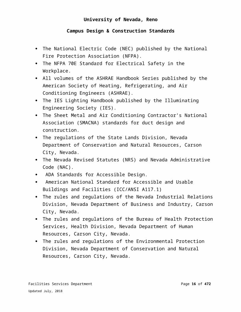
Construction (AITC). The National Electric Code (NEC) published by the National Fire Protection
Association (NFPA). The NFPA 70E Standard for Electrical Safety in the Workplace. All volumes of the ASHRAE Handbook Series published by the American Society
of Heating, Refrigerating, and Air Conditioning Engineers (ASHRAE). The IES Lighting Handbook published by the Illuminating Engineering Society
(IES). The Sheet Metal and Air Conditioning Contractor’s National Association
(SMACNA) standards for duct design and construction. The regulations of the State Lands Division, Nevada Department of Conservation
and Natural Resources, Carson City, Nevada. The Nevada Revised Statutes (NRS) and Nevada Administrative Code (NAC). ADA Standards for Accessible Design. American National Standard for Accessible and Usable Buildings and Facilities
(ICC/ANSI A117.1) The rules and regulations of the Nevada Industrial Relations Division, Nevada
Department of Business and Industry, Carson City, Nevada. The rules and regulations of the Bureau of Health Protection Services, Health
Division, Nevada Department of Human Resources, Carson City, Nevada. The rules and regulations of the Environmental Protection Division, Nevada
Department of Conservation and Natural Resources, Carson City, Nevada.
Facilities Services Department Page 12 of 349
Updated July, 2018

University of Nevada, Reno
Campus Design & Construction Standards
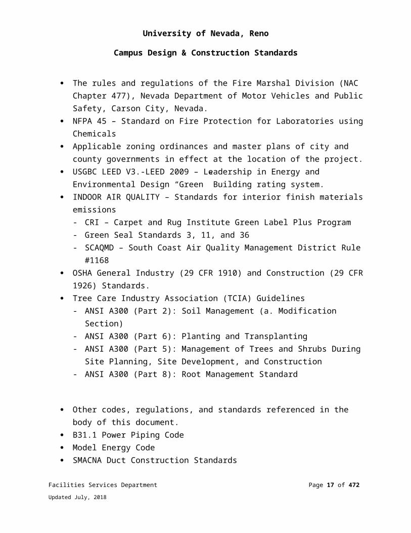
The rules and regulations of the Fire Marshal Division (NAC Chapter 477), Nevada Department of Motor Vehicles and Public Safety, Carson City, Nevada.
NFPA 45 – Standard on Fire Protection for Laboratories using Chemicals Applicable zoning ordinances and master plans of city and county governments
in effect at the location of the project. USGBC LEED V3.-LEED 2009 – Leadership in Energy and Environmental
Design “Green” Building rating system. INDOOR AIR QUALITY – Standards for interior finish materials emissions
- CRI – Carpet and Rug Institute Green Label Plus Program- Green Seal Standards 3, 11, and 36- SCAQMD – South Coast Air Quality Management District Rule #1168
OSHA General Industry (29 CFR 1910) and Construction (29 CFR 1926) Standards.
Tree Care Industry Association (TCIA) Guidelines- ANSI A300 (Part 2): Soil Management (a. Modification Section)- ANSI A300 (Part 6): Planting and Transplanting- ANSI A300 (Part 5): Management of Trees and Shrubs During Site Planning,
Site Development, and Construction- ANSI A300 (Part 8): Root Management Standard
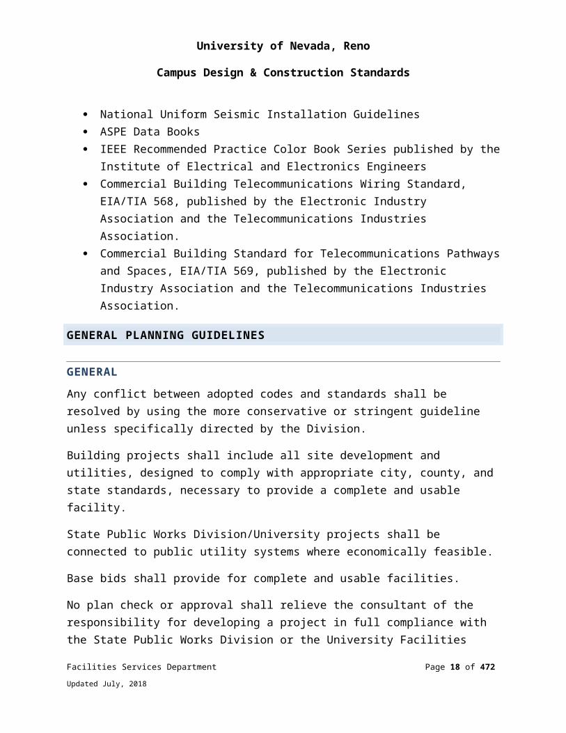
Other codes, regulations, and standards referenced in the body of this document. B31.1 Power Piping Code Model Energy Code SMACNA Duct Construction Standards National Uniform Seismic Installation Guidelines ASPE Data Books IEEE Recommended Practice Color Book Series published by the Institute of
Electrical and Electronics Engineers Commercial Building Telecommunications Wiring Standard, EIA/TIA 568,
published by the Electronic Industry Association and the Telecommunications Industries Association.
Commercial Building Standard for Telecommunications Pathways and Spaces, EIA/TIA 569, published by the Electronic Industry Association and the Telecommunications Industries Association.
GENERAL PLANNING GUIDELINES
Facilities Services Department Page 13 of 349
Updated July, 2018

University of Nevada, Reno
Campus Design & Construction Standards
GENERALAny conflict between adopted codes and standards shall be resolved by using the more conservative or stringent guideline unless specifically directed by the Division.
Building projects shall include all site development and utilities, designed to comply with appropriate city, county, and state standards, necessary to provide a complete and usable facility.
State Public Works Division/University projects shall be connected to public utility systems where economically feasible.
Base bids shall provide for complete and usable facilities.
No plan check or approval shall relieve the consultant of the responsibility for developing a project in full compliance with the State Public Works Division or the University Facilities Services Adopted Standards and applicable Federal, State, and local laws.
VARIANCESVariances from the requirements of the referenced model codes, these Adopted Standards, or reviewing authorities shall only be granted by the Division.
Requests for variances shall be made in writing to the University Facilities Services Department in a timely manner.
ASBESTOS SURVEYSIn accordance with NAC 618.961, before commencement of a renovation or demolition project that will disturb building material that may contain asbestos, samples of each suspect material must be collected by a licensed inspector and analyzed for asbestos content.
Any substance found to contain asbestos shall result in the project being subject to NAC 618.850 through 618.986. Refer to Division 2, Existing Conditions.
SUSTAINABILITY AND GREEN DESIGNSee Division 1 General Requirements
ACCESSIBILITY
Facilities Services Department Page 14 of 349
Updated July, 2018
University of Nevada, Reno
Campus Design & Construction Standards
All buildings and facilities customarily used by the public or offering employment opportunities for the disabled shall comply with adopted barrier-free design standards.
Primary public and employee entrances to public buildings shall be equipped with power assisted or accessible doors as appropriate.
Walkways, steps, ramps, and accessible routes shall have non-slip surfaces.
Mechanical and electrical equipment rooms shall permit the easy installation, maintenance and removal of equipment. Direct access to the outside is preferable.
For all new or remodeled laboratories, a complete list of chemicals to be submitted with design documents.
Each office building shall be furnished with an adequate number of bicycle stands.
Space Standards - the following table shall be used as a guide in assigning office space to the University personnel.
SPACE ASSIGNMENT GUIDE
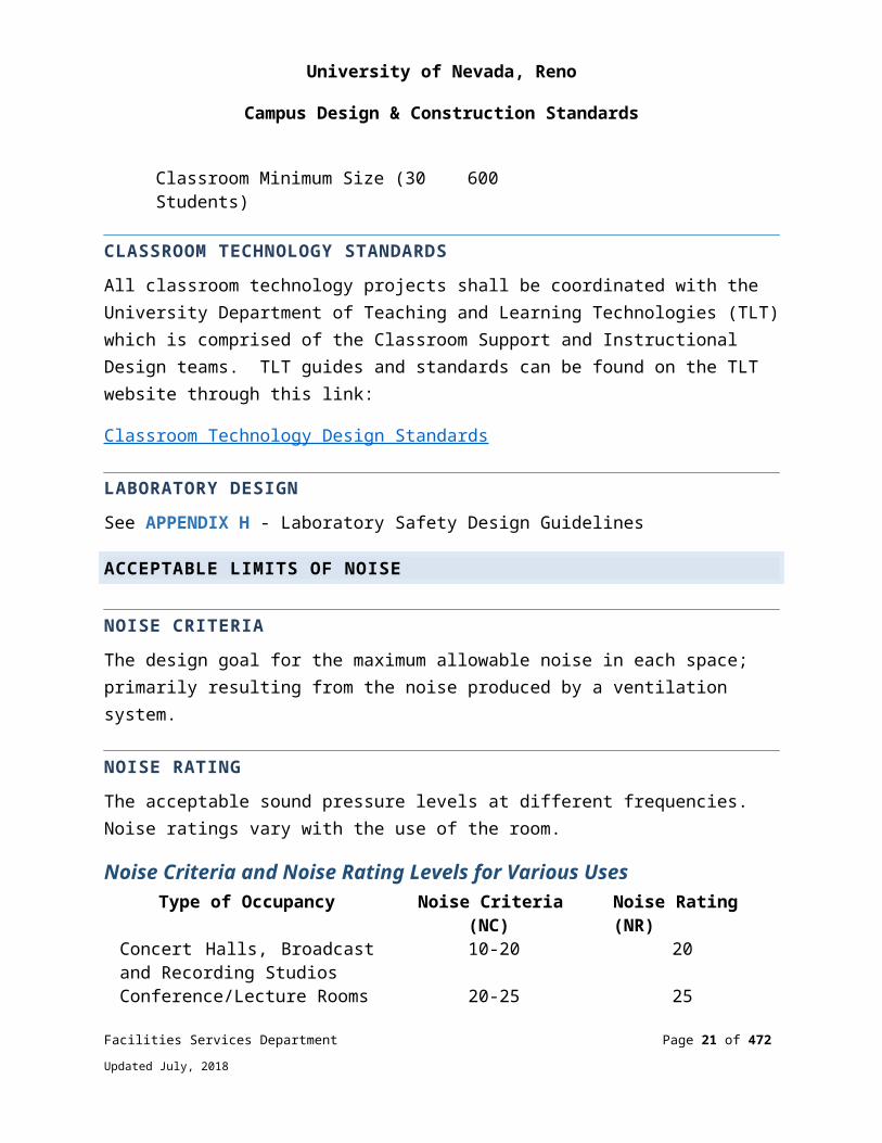
Classification Suggested Allowable Space (Sq. Ft.)Director of Departments/Deans/Chairs 200Large Office 170Two Person Office 140-170Standard Office 100-120Clerical Support (open office setting) 80Custodial Closets 60Conference Room (14) 300Classroom Minimum Size (30 Students)
600
CLASSROOM TECHNOLOGY STANDARDSAll classroom technology projects shall be coordinated with the University Department of Teaching and Learning Technologies (TLT) which is comprised of the Classroom Support and Instructional Design teams. TLT guides and standards can be found on the TLT website through this link:
Facilities Services Department Page 15 of 349
Updated July, 2018
University of Nevada, Reno
Campus Design & Construction Standards
Classroom Technology Design Standards
LABORATORY DESIGNSee APPENDIX H - Laboratory Safety Design Guidelines
ACCEPTABLE LIMITS OF NOISE
NOISE CRITERIAThe design goal for the maximum allowable noise in each space; primarily resulting from the noise produced by a ventilation system.
NOISE RATINGThe acceptable sound pressure levels at different frequencies. Noise ratings vary with the use of the room.
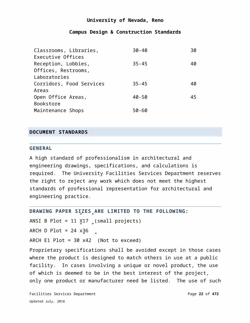
Noise Criteria and Noise Rating Levels for Various UsesType of Occupancy Noise Criteria (NC) Noise Rating (NR)
Concert Halls, Broadcast and Recording Studios
10-20 20
Conference/Lecture Rooms 20-25 25Classrooms, Libraries, Executive Offices
30-40 30
Reception, Lobbies, Offices, Restrooms, Laboratories
35-45 40
Corridors, Food Services Areas 35-45 40Open Office Areas, Bookstore 40-50 45Maintenance Shops 50-60
DOCUMENT STANDARDS
GENERALA high standard of professionalism in architectural and engineering drawings, specifications, and calculations is required. The University Facilities Services Department reserves the right to reject any work which does not meet the highest standards of professional representation for architectural and engineering practice.
Facilities Services Department Page 16 of 349
Updated July, 2018
University of Nevada, Reno
Campus Design & Construction Standards
DRAWING PAPER SIZES ARE LIMITED TO THE FOLLOWING:ANSI B Plot = 11”X17” (small projects)
ARCH D Plot = 24”x36”
ARCH E1 Plot = 30”x42” (Not to exceed)
Proprietary specifications shall be avoided except in those cases where the product is designed to match others in use at a public facility. In cases involving a unique or novel product, the use of which is deemed to be in the best interest of the project, only one product or manufacturer need be listed. The use of such products shall be approved by the University of Nevada, Reno Facilities Services Department prior to specifying.
Specifications which call for a product by specific brand or trade name shall be followed by the words “or approved equal”.
DOCUMENTS, DRAWINGS AND SPECIFICATIONSArchitectural In addition to standard architectural plan sheets, the set shall include cross sections, roof plans, complete door and window schedules, and sufficient sections and details to fully describe the architectural portions of the work.
A title sheet shall be included for the entire drawing set containing the following information:
I. Name of project and project number II. Location of projectIII. Name, address and seal of designing architect and all professional
engineering consultantsIV. Index of all drawings included in the setV. Basis of design information shall be shown on the title sheet, heavily
boxed in, and including the following:i. IBC Building Code Edition and applicable mechanical,
plumbing, electrical, fire and energy conservation, and accessibility codes
ii. Site Areaiii. Floor Area(s)iv. Allowable Building Area and Heightv. Occupancy Group(s)
Facilities Services Department Page 17 of 349
Updated July, 2018
University of Nevada, Reno
Campus Design & Construction Standards
vi. Exiting Plan with Occupancy Loadsvii. Type of Constructionviii. Fire Resistive Ratings (Table 601)ix. Required Separationsx. Fire Sprinkler Requirementsxi. Alarm Systemsxii. Plumbing Fixture Countxiii. Number of Storiesxiv. Maximum Heightxv. Zoningxvi. Set Backsxvii. Insulation Providedxviii. Allowable Live Loadings for Roofs and Floorsxix. Seismic Zone and Seismic Design Dataxx. Wind Speed and Exposurexxi. Allowable Soil Bearingxxii. Design Stresses for Building Materialsxxiii. List of all special inspection requirementsxxiv. List of all deferred submittal requirementsxxv. List of chemicals and quantities to be utilized in
work areas
A “limit” of work area designating the area allocated to the contractor for storage and operations, and on-site dedicated construction parking, shall be shown on the architectural site plan.
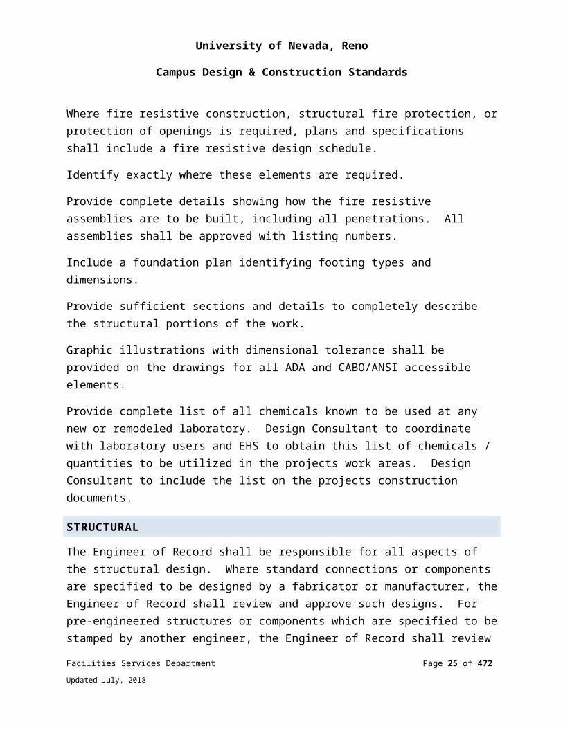
Where fire resistive construction, structural fire protection, or protection of openings is required, plans and specifications shall include a fire resistive design schedule.
Identify exactly where these elements are required.
Provide complete details showing how the fire resistive assemblies are to be built, including all penetrations. All assemblies shall be approved with listing numbers.
Include a foundation plan identifying footing types and dimensions.
Provide sufficient sections and details to completely describe the structural portions of the work.
Facilities Services Department Page 18 of 349
Updated July, 2018

University of Nevada, Reno
Campus Design & Construction Standards
Graphic illustrations with dimensional tolerance shall be provided on the drawings for all ADA and CABO/ANSI accessible elements.
Provide complete list of all chemicals known to be used at any new or remodeled laboratory. Design Consultant to coordinate with laboratory users and EHS to obtain this list of chemicals / quantities to be utilized in the projects work areas. Design Consultant to include the list on the projects construction documents.
STRUCTURAL
The Engineer of Record shall be responsible for all aspects of the structural design. Where standard connections or components are specified to be designed by a fabricator or manufacturer, the Engineer of Record shall review and approve such designs. For pre-engineered structures or components which are specified to be stamped by another engineer, the Engineer of Record shall review and approve such designs for compliance with the structural design criteria for the project.
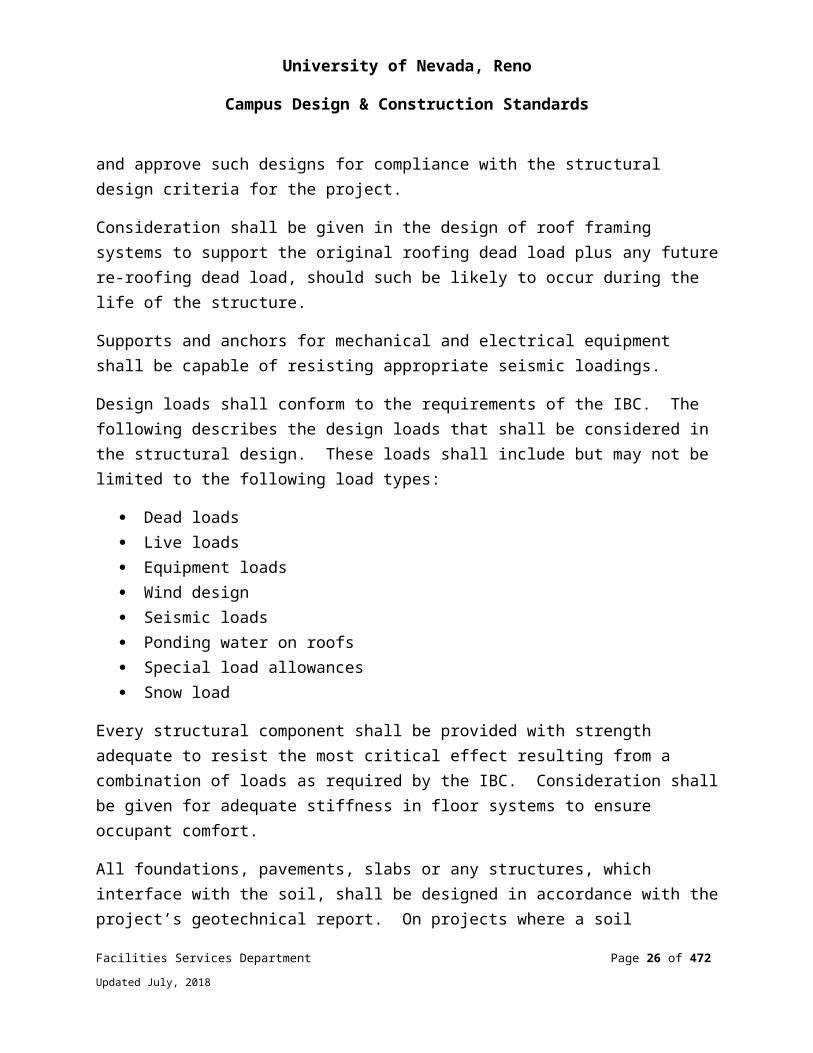
Consideration shall be given in the design of roof framing systems to support the original roofing dead load plus any future re-roofing dead load, should such be likely to occur during the life of the structure.
Supports and anchors for mechanical and electrical equipment shall be capable of resisting appropriate seismic loadings.
Design loads shall conform to the requirements of the IBC. The following describes the design loads that shall be considered in the structural design. These loads shall include but may not be limited to the following load types:
Dead loads Live loads Equipment loads Wind design Seismic loads Ponding water on roofs Special load allowances Snow load
Every structural component shall be provided with strength adequate to resist the most critical effect resulting from a combination of loads as required by the IBC.
Facilities Services Department Page 19 of 349
Updated July, 2018

University of Nevada, Reno
Campus Design & Construction Standards
Consideration shall be given for adequate stiffness in floor systems to ensure occupant comfort.
All foundations, pavements, slabs or any structures, which interface with the soil, shall be designed in accordance with the project’s geotechnical report. On projects where a soil investigation is not performed, foundations shall be designed using the guidelines of the IBC.
All footings and foundations shall extend below the frost line, or to depths recommended in the soils report. The minimum bearing depth for footings shall be 24 inches below finished grade.
The structural drawings shall include, as a minimum, the following:
General structural notes including a basis of design, loading information, allowable design stresses, basic information regarding material used on the project.
Design Consultant to include a complete listing of all structurally required special inspection requirements on the construction documents code analysis sheet.
A framing plan for each floor and roof, showing structural connections and vertical support systems. A foundation plan identifying footing types and dimensions.
Sufficient sections and details to completely describe the structural portions of the work.
Structural calculations are required for all aspects of the structural design, including vertical and lateral load carrying systems. Calculations shall be neatly prepared and organized so that an independent peer reviewer can check the validity and completeness of the calculations. Computer programs used shall be clearly identified and input and results fully documented.
MECHANICAL
HVAC, plumbing, and fire sprinkler drawings shall adhere to the following criteria:
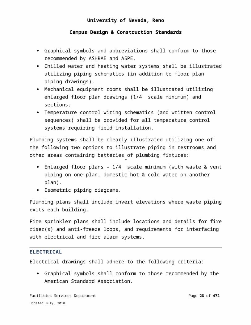
Graphical symbols and abbreviations shall conform to those recommended by ASHRAE and ASPE.
Chilled water and heating water systems shall be illustrated utilizing piping schematics (in addition to floor plan piping drawings).
Facilities Services Department Page 20 of 349
Updated July, 2018
University of Nevada, Reno
Campus Design & Construction Standards
Mechanical equipment rooms shall be illustrated utilizing enlarged floor plan drawings (1/4” scale minimum) and sections.
Temperature control wiring schematics (and written control sequences) shall be provided for all temperature control systems requiring field installation.
Plumbing systems shall be clearly illustrated utilizing one of the following two options to illustrate piping in restrooms and other areas containing batteries of plumbing fixtures:
Enlarged floor plans - 1/4” scale minimum (with waste & vent piping on one plan, domestic hot & cold water on another plan).
Isometric piping diagrams.
Plumbing plans shall include invert elevations where waste piping exits each building.
Fire sprinkler plans shall include locations and details for fire riser(s) and anti-freeze loops, and requirements for interfacing with electrical and fire alarm systems.
ELECTRICALElectrical drawings shall adhere to the following criteria:
Graphical symbols shall conform to those recommended by the American Standard Association.
Buildings with extensive electrical systems shall be clearly illustrated with three separate floor plans of each floor. One floor plan shall show the lighting system, a second the power system, and a third the communications and signaling systems.
Lighting and power panel schedules shall be included on the drawings. Separate enlarged (1/4” scale minimum) floor plans shall be included for building
areas with extensive electrical equipment. Special fixture and equipment supports shall be fully detailed where necessary to
clarify the designer’s intent. All electrical circuit outlets shall be shown with the circuit number or numbers to
which each is connected. Wiring diagrams shall be included for clarification for all special control systems. Provide settings for circuit breakers with electronic trip units. Provide an electrical single line diagram for the project. See Drawing # 017839-
1, Single Line Diagram – Electrical
Facilities Services Department Page 21 of 349
Updated July, 2018
University of Nevada, Reno
Campus Design & Construction Standards
Provide an electrical site plan indicating all site conduit, duct banks, lighting, mechanical equipment connections, and electrical equipment including pad mounted switches, transformers, generators, load banks, panels, etc.
Provide an electrical lighting site plan with point by point lighting illumination calculations indicating max/min ratios, average foot candles. Use .85 light loss factor for all fixtures.
On the drawings provide NEC load calculations and energy code compliance calculations.
Lighting fixture schedule with descriptions, lamp type, wattage, and ordering information.
Equipment schedules for feeders, kitchen equipment, mechanical connections, etc.
Fire alarm floor plans including location of control panels, remote annunciation panels, each device, sound levels for each annunciation device, riser diagram indicating all devices and cable types.
CIVIL/UNDERGROUND UTILITIESFor all new civil and underground utility work to be done on University properties, the Design Consultant of contract shall be responsible for providing record as-built utility drawings when project is completed. The Design Consultant is required to make sure all sub-design consultants (Civil, Domestic, Fire, Electrical, Mechanical, Plumbing, etc.) including all private utility companies (i.e., TMWA, NV Energy, etc.) involved with project follow the same electronic drawing format and final as-built/GPS deliverable process (no exceptions). The Design Consultant of contract shall incorporate all utilities within the scope of the project into one final Site Utility Plan.
The General Contractor shall be responsible for providing the Design Consultant with accurate as-built utility information throughout the utility installation phase. The General Contractor is required to hire the services of a Professional Licensed Surveyor prior to starting any utility work to map, via Global Positioning System (GPS), all new and existing utilities. The Project Coordinator shall determine if the services of a Professional Licensed Surveyor are required or agreed-upon substitute per the scope of utility work.
During the initial utility installation phase, the Design Consultant of contract shall be required to submit a progress partial compliance check set to the University Project Coordinator within the agreed-upon set time frame for review and compliance (no
Facilities Services Department Page 22 of 349
Updated July, 2018

University of Nevada, Reno
Campus Design & Construction Standards
exceptions). The Project Coordinator shall determine the time frame for partial and final as-built utility deliverables based upon the scope of utility work
Partial and final payment shall be withheld from the Design Consultants and General Contractors contract until such partial and final utility as-built deliverables are completed to the University’s satisfaction. Failure to produce accurate utility as-built record drawings in a timely manner shall result in monetary damages subtracted from withholdings from final payment equal to fees assessed by a 3rd party Professional Licensed Surveying Consultant to complete the work per the University Design and Construction Standards.
CIVIL/UNDERGROUND UTILITIES DATUMSDrawings shall be NAD 1983 Nevada State Plane Zone West 2703 US Survey Foot horizontal and NGVD29 vertical. If the project is not in Nevada, use appropriate state plane coordinate system. Architectural drawings may use architectural units on a coordinate system convenient for the project, and reference NAD83 coordinates at each building corner. Drawings shall be in 2D with z = 0 feet. 3D and BIM documents are welcome in addition, but not in lieu of standard submittals.
Horizontal and vertical coordinate system to be referenced and survey benchmark location(s) indicated on all design drawings. All coordinates to be Nevada State Plane, NAD 1983. Include ground to grid conversion scale factor if submitting GPS coordinates in ground.
Specify the horizontal x-y coordinates at every pipe bend.
Use 1” = 40’ scale for plans, or agreed-upon scale.
Piping inverts shall have the vertical elevation identified to an accuracy of one tenth of a foot.
Show all other existing utilities on plan.
Show grade contours on all plans, not less than 2-foot intervals.
Always indicate pipe slope and direction of slope.
Must show both the supply and return lines for high temp hot water piping, a single line representation is not acceptable.
Facilities Services Department Page 23 of 349
Updated July, 2018

University of Nevada, Reno
Campus Design & Construction Standards
Must show manhole and manhole piping details in scaled plan and sections, not less than ¼” = 1’ scale.
Thermal expansion (high temp hot water) must be accommodated by expansion loops for stated design temperature conditions. Anchors and guides must be indicated on plan and profile with specific dimensions and details.
Indicate and detail thrust blocks for all pressure systems. Specify piping system joint type: bell & spigot, mechanically restrained joint, welded, threaded, flanged etc.
All plans to have north arrow indication.
For high temperature hot water piping, piping design shall be in accordance with ASME/ANSI B31.1, Power Piping, latest edition. A thermal stress analysis must be completed for all buried piping and piping inside of manholes.
AIA Layering Standards are recommended but not required.
All piping and duct banks must include invert elevations.
All manholes to be to scale.
Pipe diameters must be indicated. (NPS).
Duct banks must indicate # of conduit, size of conduit and arrangement; e.g. 2 x 2. For electrical, indicate conductor sizes.
All valves to be indicated.
All contours at two-foot intervals.
All bends/changes of direction must have horizontal GPS coordinates identified in NAD 1983 coordinate system. Final underground utility record drawings “as-builts” must have ground to grid conversion scale factor listed on drawings.
Provide a tracer wire with suitable access above all non-metallic utilities (no exceptions).
All underground utility marking shall be in accordance with NRS 455, ‘Subsurface Utilities Marking Requirements’.
SURVEYING / GPS / AND DATUM REQUIREMENTS.
Facilities Services Department Page 24 of 349
Updated July, 2018
University of Nevada, Reno
Campus Design & Construction Standards
As-built utility locations by global positioning system (GPS): The General Contractor shall obtain the services of a Nevada Licensed Professional Land Surveyor (unless approved otherwise by the Project Coordinator) to provide as-built locations and elevations for constructed utilities. The locations and elevations shall be tied using global positioning equipment. The tied locations shall be based on Nevada State Plane West Zone (NAD 83/94) as determined with Real Time Kinematic (RTK) GPS observations with corrections transmitted by Washoe County Continuous Operating Reference Station (CORS) “Reno.”
Accuracy: Horizontal Accuracy: +/- 0.20 feet; Vertical Accuracy: +/- 0.20 feet.
Format: The GPS information shall be provided to the University so that they can re-establish the tied points using global positioning equipment.
GPS point files shall be submitted in .CSV (Comma-separated values) in excel table format with point descriptions based on the following below.
GPS coordinates shall be taken for all existing utilities and listed as “E” with descriptions listed below.
All abandoned utilities that are left in place shall be located and identified by GPS and listed as “E-ABND” with descriptions listed below.
All new utilities locations shall be identified with GPS and listed as “N” with descriptions listed below.
Include sizes of new and existing pipe sizes.
The tied point shall be as followsSanitary Sewer and Storm Drain:
Location at the center of all manholes with elevation at rim and invert. Location and top of pipe elevation at any horizontal or vertical angle points. Location and top of pipe elevation at points of entry into buildings. Location and top of pipe elevation at all points of crossing with other utilities.
Water (domestic, fire, irrigation mains), Natural Gas, High Temperature Hot Water, Chiller Piping, and Mechanical Systems:
Location and top of pipe elevation at all horizontal or vertical angle points.
Facilities Services Department Page 25 of 349
Updated July, 2018
University of Nevada, Reno
Campus Design & Construction Standards
Location and top of pipe elevation at all valves, fittings, service tees and at points of entry into buildings.
Locations and top of pipe elevation at all points of crossing with other utilities.
Electrical, Communication and Fiber:
Location and top of duct back, or encasement, at all horizontal or vertical angle points.
Location and top of duct back, or encasement, at all points of entry into vaults, hand holes, transformers, switches and buildings.
Location and top of duct back, or encasement, at all points of crossings with other utilities.
Location and elevations at four corners of all vaults, hand holes, transformers and switches.
The following types of utilities shall be “As-built” by Global Positioning System: Sanitary Sewer and Storm Drain, Water, Irrigation (mains, valve boxes, timers), Natural Gas, High Temperature Hot Water, Chiller Piping, Mechanical Systems, Electrical (medium and low voltage), Communication and Fiber.
PROJECT CLOSEOUT DOCUMENTS / DELIVERABLESDeliverablesSee APPENDIX J for As-Built Transmittal Template for Project Deliverables.
Record drawings should exactly match hard copy documents. The engineer’s stamp may be omitted from the electronic copy.
Media/CompressionSubmitted via web-based file transfer program or on CD accompanied by as-built transmittal document. See APPENDIX J for standard template for project deliverables.
Each record drawing sheet should have a corresponding CAD file. Multiple drawing sheets may not be submitted within a single CAD file. CAD file names should be identical to hard-copy drawing sheet identification numbers. Special characters should be limited to dashes. For example, the CAD file for sheet “A-1” should be named “A-1.dwg.”
Facilities Services Department Page 26 of 349
Updated July, 2018

University of Nevada, Reno
Campus Design & Construction Standards
Zipped files should be named “Project name.exe” and not UNR.exe. Only self-extracting archives should be used. Directions must be included with the transmittal and electronically in the root directory of the electronic media in *.txt format.
A full set of record drawings compiled into one PDF document, as well as CAD drawings, are required as part of the electronic deliverable package (no exceptions). Final Record Drawing printed hard copies are not required.
If unreferenced External References (XREFS) are used to create drawings, they should be removed before delivering final record drawings.
All font files and line types shall be included in the submittal package. The consultant is responsible for transfer of license for any purchased line types or fonts.
All color table books (. ctb files) used for plotting colors and line weights shall be included in the submittal package.
Electronic Drawing FormatRecord drawings shall be in a currently supported version of AutoCAD. DXF and DWF are not acceptable. PDF or TIFF files should accompany the submittal, but may not be submitted in lieu of DWGs. DWG files should be last saved with the default ACAD.MNU menu. If converting from a format other than DWG, ensure all graphic elements are preserved.
DraftingAll lines must be snapped/closed.
Drawings shall not contain multiple overlaid lines or lines with multiple segments unless overlaid lines or adjacent line segments are assigned to different layers.
Drawings shall be purged of empty, unused, or non-essential drawing data.
All drawings will be developed in full scale format (one foot = one foot) and will be maintained as an integrated whole with individual drawings plotted using paper space.
Entity colors shall be defined “by layer.”
Blocks shall be created the corresponding layer (electrical block on electrical layer), or on layer 0 if there is no corresponding layer. Use 1:1 scale to create blocks and insert at the appropriate scale.
Facilities Services Department Page 27 of 349
Updated July, 2018
University of Nevada, Reno
Campus Design & Construction Standards
Attributes shall be defined on layer 0 (zero).
AIA layering standards are preferred.
Only native AutoCAD fonts, line types, and hatch pattern shall be used.
All shades and fills must be decipherable when the drawing is reproduced using photocopy methods.
CONSTRUCTION Construction Signage and FencingTemporary construction signs shall be 6’-0” wide by 3’-6” high. Lettering shall be ROMAN style. Lettering color for University of Nevada, Reno shall be Nevada Blue and all other lettering black. Background color to be white. Lettering to be minimum ¼” to maximum of 2-3/4” high.
Sign format as follows:
University of Nevada, Reno Project Title Completion Date Contractor Name Architect Name Structural Engineer Name MEP Engineers Name(s)
All construction sites to be enclosed at limits of work boundary as established at the construction kick-off meeting by 6’-0” high chain link fencing, unless otherwise approved by Facilities Services.
Construction Waste ManagementSee Division 1 General Requirements
End of Section 2.0
ARCHITECTURAL DESIGN GUIDELINES
Facilities Services Department Page 28 of 349
Updated July, 2018
University of Nevada, Reno
Campus Design & Construction Standards
Facilities Services Department Page 29 of 349
Updated July, 2018
University of Nevada, Reno
Campus Design & Construction Standards
SECTION 3: CAMPUS SIGNAGE POLICY AND STANDARDS
SUMMARY
The University recognizes the need for a comprehensive, coordinated system of campus signage. It is important for signage to provide a distinct identity for the University of Nevada, Reno and to help establish a welcoming image. Signage can enhance the character of the University by providing direction and information regarding campus buildings, departments, events, and services. Every effort is made to limit signage on campus with the understanding that some signage is essential to support the mission of the University. Uniformity of design is necessary to contribute to the overall aesthetic value of the campus. All signage must be approved by the Facilities Resource Committee.
The signage policy for the University facilitates an aesthetically consistent approach to signage across campus. The policy is concerned with general design standards for all campus signage, and also with the priority areas where implementation of these new standards shall be given immediate attention. All logos will be consistent with the University trademarked logo criteria.
The purpose of this policy is to set standards for the departments of the University to follow when making decisions about campus signage. These guidelines are intended to encourage a friendly, welcoming atmosphere where the necessary information is readily available for visitors, new students and staff to become easily familiarized with the campus.
Requests for signs in common or shared areas must be reviewed and approved by the Facilities Resource Committee.
TYPES OF SIGNAGE
CAMPUS IDENTIFICATION SIGNAGERefers to all signage on the periphery of the campus, which notifies visitors that they have arrived at the University of Nevada Reno. Three categories of identification signage will be addressed.
Facilities Services Department Page 30 of 349
Updated July, 2018

University of Nevada, Reno
Campus Design & Construction Standards
Gateway/Entry/Portal SignageEntry signage serves to notify visitors, students, and passersby that they have arrived at the University of Nevada, Reno. Gateway/portal signage is an important part of campus way-finding and can enhance a visitor’s arrival to the University.
Each entry location to the campus provides unique access, traffic, and visibility opportunities. Therefore, criteria for all entry signage is determined on a case by case bases through collaboration with Facilities Services and Marketing and Communications. Final approval is provided by the Facilities Resource Committee.
Campus Interior Traffic/Vehicular SignageTraffic/Vehicular signage marks the campus intersections and is easily read from automobiles. These signs are used to direct the vehicle user through the campus to parking areas and points of interest.
Pedestrian Way-finding SignagePedestrian signage provides way-finding information to pedestrians on campus and is standardized.
Pedestrian signs may identify key departments within certain buildings.
Building Identification SignageRefers specifically to signage that identifies a building on the exterior. Three categories of building identification signage are discussed:
Building Dedication PlaquesStandard plaques shall be placed on Nevada System of Higher Education buildings as follows:
Building plaques should be installed for the building dedication. The plaque should be one piece, cast bronze, wall mounted in main entrances to
building. Plaques should not exceed 36” x 36” and may include the following:
Building name and year of completion University Institution Special message if appropriate Names of Regents*
Facilities Services Department Page 31 of 349
Updated July, 2018
University of Nevada, Reno
Campus Design & Construction Standards
Governor* Chancellors* Institution President(s)* State Public Works Division Name of Design Firm
*At the time of dedication
Affixed Building SignageLettering: Design and placement standards for new affixed building signage shall be consistent with current design and construction standards. See APPENDIX I for typical building lettering detail
This type of signage is mounted onto the exterior face of a building and is typically lettering (not panels).
Free Standing SignageTypically used for multiple vendors in a building.
REGULATORY SIGNAGEParking and Traffic SignageParking signage shall be coordinated through Facilities Services.
ADA and Access SignageTypical flag sign posts are 3” x 3” x 8” long tube steel, mounted 24 inches in concrete.
Flag is typically 1/8” x 12” x 12” steel, welded to steel post for strength.
Interior Signage (See DIVISION 10: SPECIALTIES, and APPENDIX I, Signage Standard Details, for additional information on interior signage)
Directional SignageAids in guiding people within the buildings on campus. It is intended to provide directional assistance at both building lobbies and corridor junctures.
Facilities Services Department Page 32 of 349
Updated July, 2018
University of Nevada, Reno
Campus Design & Construction Standards
DirectoriesMain building directory boards are to be mounted within each main entrance to a building.
The purpose of a directory is to list the locations of faculty offices, and other important rooms, under the department with which they are associated. It is evident that due to limited space, one directory board will not be able to list all locations, especially for buildings that house a multitude of departments.
Main directories will include a listing of each department and a summary of floors and/or rooms occupied by these departments.
Main building directory boards are to be mounted within each main entrance to a building.
Interior Way-Finding SignageInterior way-finding signage directs people at various junctures, or “forks in the road” within buildings.
Building maps (floor plans) are installed at these locations.
These signs are to be installed in areas where several corridors meet, as well as on walls opposite to, or near, elevators. Mounting height is to be 60 inches from the floor to the center of the sign.
Room SignageIncludes: room numbers, occupant name and room space identification.
Emergency Information SignageEgress Signage is used to assist people with exiting a building safely and efficiently to the designated assembly area.
Hazards and Emergency Contact Signage is posted at the entry to areas containing hazards with information of the type of hazard, access requirements, and contact information of responsible parties.
RESIDENTIAL LIFE SIGNAGE
Facilities Services Department Page 33 of 349
Updated July, 2018
University of Nevada, Reno
Campus Design & Construction Standards
The University Logo is typically not displayed on buildings, however, Residential Life may, at their cost, install the block “N” logo sign, meeting Marketing and Communication specifications, on residential buildings. Residential Life will collaborate with Facilities Services for sign size and location. Facilities Services retains final approval within parameters provided by the Facilities Resource Committee. The sign may not interfere with building entry signage, may be no larger than 60 inches by 60 inches and will not be illuminated. Residential Life is responsible for the maintenance and repair of installed signs.
End of Section 3
CAMPUS SIGNAGE POLICY & STANDARDS
Facilities Services Department Page 34 of 349
Updated July, 2018
University of Nevada, Reno
Campus Design & Construction Standards
DIVISION 1: GENERAL REQUIREMENTS
013300 – SUBMITTAL PROCEDURES
All submittal requirements shall be stated in the project specification. The University of Nevada, Reno Facilities Services Department requires electronic versions all submittals, shop drawings and correspondence for the University records. In addition, specifications shall identify number and format of copies for contractor uses. Contractors shall obtain comments and approval of submittals from both Facilities Services and A/E. (Architects/Consultant team).
Specifications shall require all supplied materials be asbestos free. The contractor(s) shall provide certification that all materials supplied are asbestos free.
The form shall be signed by the supplying contractor, the general contractor and the architect to ensure the review process is accomplished. Materials brought to the job that are not certified shall be removed until certified. This certification is not required for uncoated or unfinished steel, aluminum, brass, masonry, concrete, or glass.
018113 – SUSTAINABLE DESIGN REQUIREMENTS - LEED
It is University policy that all campus building construction meets or exceeds LEED Silver equivalency.
017419 – CONSTRUCTION WASTE MANAGEMENT AND DISPOSAL
University policy is to salvage and recycle as much nonhazardous demolition and construction waste as possible.
END OF DIVISION 1
GENERAL REQUIREMENTS
Facilities Services Department Page 35 of 349
Updated July, 2018
University of Nevada, Reno
Campus Design & Construction Standards
DIVISION 2: EXISTING CONDITIONS
028213 - ASBESTOS ABATEMENT
SYSTEM DESIGN AND PERFORMANCE REQUIREMENTSState and Federal regulations require that every remodel, renovation or demolition project be surveyed for the presence of asbestos and lead prior to the project’s commencement. The survey shall be specific to the project itself and must be generated and signed by the licensed inspector for each project undertaken.
Review of a building’s historical data is but one component of the required survey. Many variables influence the validity of historical survey data. Questions about the scope of prior remodels or renovations shall be answered. Previous abatement activities shall be quantified and documented. Additional samples of all new or modified construction materials shall be collected. These and other concerns shall be addressed when preparing the required survey report.
Asbestos and lead surveys shall be performed in advance of doing any demolition, construction, or abatement work. When abatement work is needed and is required to go to bid, a licensed asbestos consultant shall write the abatement specifications.
The University Asbestos Program Guide is available on the Environmental Health and Safety Department website.
02200 - EARTHWORK
SYSTEM DESIGN AND PERFORMANCE REQUIREMENTSConsultant shall follow the earthwork design criteria as established in the Geotechnical Report. Any deviations from the Geotechnical Report recommendations shall be approved by both the Geotechnical Engineer as well as the UNR Project Manager.
In cases where no Geotechnical Report was prepared and conditions warrant initiation of a report, consultant shall make their request for additional information to the UNR Project Manager.
EXISTING UTILITIES Location of existing underground utilities shall be coordinated with both “USA Dig” and University Planning and Construction, as there are both utility and University owned underground installations on campus.
Facilities Services Department Page 36 of 349
Updated July, 2018
University of Nevada, Reno
Campus Design & Construction Standards
Protect existing structures, utilities, sidewalks, pavements, and other facilities from damage caused by settlement, lateral movement, undermining, washout, and other hazards created by earthwork operations.
Unclassified Excavation Excavate to sub-grade elevations regardless of the character of surface and subsurface conditions encountered. Unclassified excavated materials may include rock, soil materials, and obstructions. No changes in the contract sum or the contract time shall be authorized for rock excavation or removal of obstructions.
Fill unauthorized excavation under foundations or wall footings by extending bottom elevation of concrete foundation or footing to excavation bottom, without altering top elevation. Lean concrete fill, with 28-day compressive strength of 2500 psi, may be used when approved by the project’s Architect of Record.
Testing Agency A qualified independent geotechnical engineering testing agency shall perform field quality-control testing.
Protecting Graded AreasProtect newly graded areas from traffic, freezing, and erosion. Keep free of trash and debris.
Repair and reestablish grades to specified tolerances where completed or partially completed surfaces become eroded, rutted, settled, or where they lose compaction due to subsequent construction operations or weather conditions.
Where settling occurs before project correction period elapses, remove finished surfacing, backfill with additional soil material, compact, and reconstruct surfacing.
DisposalRemove surplus satisfactory soil and waste material, including unsatisfactory soil, trash, and debris, and legally dispose of it off Campus property.
DrainageSite development shall ensure positive drainage and minimum erosion. Rolled curbs shall not be used.
Storm Protection PlanCreate waddles around storm drains and any areas where there is soil erosion potential.
Facilities Services Department Page 37 of 349
Updated July, 2018
University of Nevada, Reno
Campus Design & Construction Standards
Irrigation Water Management PlanContractor shall provide an irrigation water management plan for existing landscaping for the duration of the project. Tree protection per ANSI A300 Pamphlet on Construction around Trees.
End of Division 2
EXISTING CONDITIONS
Facilities Services Department Page 38 of 349
Updated July, 2018
University of Nevada, Reno
Campus Design & Construction Standards
DIVISION 3: CONCRETE
SYSTEM DESIGN AND PERFORMANCE STANDARDS
CONCRETE MATERIALSConcrete shall be proportioned, mixed and placed in accordance with the provisions of the IBC and the American Concrete Institute.
Exterior Concrete shall have minimum compressive design strength of 4,000 psi at 28 days. Horizontal application shall also contain synthetic fiber reinforcing, minimum 1.5 pounds per cubic yard of concrete.
The minimum compressive strength for concrete used in structural applications, including slabs-on-grade, shall be a minimum of 3,000 psi at 28 days.
An air-entraining admixture, resulting in 5% to 7% entrainment, shall be used for all concrete exposed to the effects of weather or freezing and thawing.
All Portland cement shall be an approved American (USA) brand conforming to ASTM C150, Type II or Type V, as recommended by the project geotechnical report. Different types of cement shall not be used in the same pour or structural member.
Admixtures containing calcium chloride shall not be specified.
Fine and coarse aggregates for normal weight concrete shall conform to the requirements of ASTM C33.
Lightweight aggregate shall conform to ASTM C33.
Water used for concrete mixing shall be clean and free from oil, acid, alkalis, organic matter, or other deleterious substances and shall conform to the requirements of ASTM C94. Drinking water is generally acceptable.
Mix designs shall be submitted to the Consultant for approval prior to any production of concrete for structures. Water-cement ratios, curing methods, and finishing requirements shall be specified to reduce cracking in the placed concrete.
A water-reducing admixture shall be specified for all concrete.
Contractor shall be fully responsible for protection of all exposed horizontal concrete and replace any such concrete damaged or defaced during set period.
Facilities Services Department Page 39 of 349
Updated July, 2018

University of Nevada, Reno
Campus Design & Construction Standards
CONCRETE REINFORCEMENTStructural concrete shall be reinforced with deformed bars conforming to ASTM A615, Grade 40 or Grade 60. Structural slabs and slab-on-grade shall be reinforced with rebar or welded wire fabric. Synthetic fiber reinforcement may be used in non-structural applications or in combination with steel reinforcing for structural applications, to control shrinkage cracking.
Reinforcing steel shall be detailed and fabricated in accordance with the Manual of Standard Practice for Detailing Reinforced Concrete Structures (ACI 315) and the CRSI Manual of Standard Practice (Concrete Reinforcing Steel Institute).
End of Division 3
CONCRETE
Facilities Services Department Page 40 of 349
Updated July, 2018

University of Nevada, Reno
Campus Design & Construction Standards
DIVISION 4: MASONRY
SYSTEM DESIGN AND PERFORMANCE STANDARDS
GENERAL MASONRY PROCEDURESMasonry design and construction, and requirements for special inspection or periodic special inspection, shall comply with the IBC recommendations and the National Concrete Masonry Association (NCMA).
Masonry construction shall be reinforced with vertical and horizontal deformed bar reinforcing. Joint reinforcing may be used in lieu of horizontal bars.
Specified requirements for continuous or periodic special inspection of masonry shall be approved by the University Facilities Services Department and/or Nevada State Public Works Division.
Where prism testing is required, the minimum strength of masonry, grout, and mortar shall be specified.
The tops of all masonry walls shall be provided with metal architectural coping or full width metal flashing installation below a cast stone, natural stone, or concrete masonry cap material.
Exposed exterior masonry shall receive two coats of a non-staining sealer prior to completion of construction.
Sandblasting visible masonry surfaces to clean off mortar shall not be permitted.
End of Division 4
MASONRY
Facilities Services Department Page 41 of 349
Updated July, 2018
University of Nevada, Reno
Campus Design & Construction Standards
DIVISION 5: METALS
051200 - STRUCTURAL STEEL FRAMING
SYSTEM DESIGN AND REQUIREMENTSAll structural steel and their connections shall be designed, fabricated and erected in accordance with the latest specifications of the American Institute of Steel Construction.
The Engineer of Record shall: (a) design and detail all connections on the structural drawings, or (b) review and approve all shop drawings, including connections designed and detailed by the Fabricator. For connections to be designed by the Fabricator, the Engineer of Record shall clearly indicate all design loads on the drawings.
All structural penetrations through roofs shall be round.
PRODUCT STANDARDS AND MANUFACTURERSStructural Steel The allowable type and grade of all structural steel, plate, bar, pipe, tubes, and bolts shall be specified in the construction documents.
Welding All welding, welding procedures and welder qualifications shall be in accordance with the American Welding Society, AWS D1.1.
05500 - METAL FABRICATIONS
SYSTEM DESIGN AND REQUIREMENTSIn general, miscellaneous metal items such as lintels, embeds, grating, ladders, bollards, stair nosing, trim, and similar architectural features shall be designed and sized to meet codes and their applications.
Handrails, both interior and exterior will be painted bronze to match the medium, bronze aluminum window and door frames, or as directed by Facilities Services to match existing door and window frames.
See detail drawings for standard design details:
Typical Handrail Detail (Drawing # 055213-1 )
Facilities Services Department Page 42 of 349
Updated July, 2018
University of Nevada, Reno
Campus Design & Construction Standards
Typical Exterior Stairs and Handrail (Drawing # 055213-2)
Typical Ramp Detail (Drawing # 055213-3)
Stairs, handrails and ramps shall comply with the latest ADA standards.
PRODUCT STANDARDS AND MANUFACTURERSMetal Surfaces, General Provide materials with smooth, flat surfaces, unless otherwise indicated. For components exposed to view in the completed Work, provide materials without seam marks, roller marks, rolled trade names, or blemishes.
Bollard and base plate shall be Trafficguard Round Post HRP or equivalent and painted UNR blue, Tiger Drylac Powder Coatings RAL 5011 049/43180 or equivalent.
End of Division 5METALS
Facilities Services Department Page 43 of 349
Updated July, 2018

University of Nevada, Reno
Campus Design & Construction Standards
DIVISION 6: WOOD, PLASTICS, AND COMPOSITES
06400 - ARCHITECTURAL WOODWORK
SYSTEM DESIGN AND PERFORMANCE REQUIREMENTSTimber design and construction shall be in accordance with the IBC, and recommendations of the American Institute of Timber Construction (AITC).
Specifications shall establish the species, grade and allowable moisture content of all wood and wood products used.
The use of exposed wood or other high maintenance materials for exterior finishes shall be avoided.
Drawer Construction Fabricate with exposed fronts fastened to sub-front with mounting screws from interior of body. Join sub-fronts, backs, and sides with glued rabbeted joints supplemented by mechanical fasteners or glued dovetail joints.
QUALITY ASSURANCE All casework must comply with American Woodwork Institute (AWI) Standards (AWS) with a minimum of custom grade or better, style as determined by the Architect. The casework fabricator shall be a licensed participant in the AWI Quality Certification Program.
SubmittalsProvide AWI Quality Certificates/labels for the shop drawings, fabrication and installation for all casework where the value of the casework exceeds $20,000
Casework must be fabricated by the manufacturer or a casework fabricator and/or installer that is a licensed participant in the AWI Quality Certification Program to install the manufacturer’s casework.
Load test requirements Grade 1, 50 lbf (22.2 kg)
for drawers not more than 3 inches high and not more than 24 inches wide
Facilities Services Department Page 44 of 349
Updated July, 2018
University of Nevada, Reno
Campus Design & Construction Standards
for drawers more than 3 inches high but not more than 6 inches high and not more than 24 inches wide
Grade 1HD-100, 100 lbf (44.5 kg)
for trash bins not more than 20 inches high and 16 inches wide
for drawers more than 6 inches high or more than 24 inches wide
for computer keyboard shelves
MATERIALSCabinet Hardware Frameless Concealed Hinges (European Type): BHMA A156.9, B01602, 170 degrees of opening, self-closing.
Adjustable Shelf Standards and Supports BHMA A156.9, B04071; with shelf rests, B04081 BHMA A156.9, B04102; with shelf brackets, B04112.
Drawer Slides BHMA A156.9.
Grade 1 and Grade 2: Side mounted; full-extension type; zinc-plated steel with polymer rollers.
Grade 1HD-100 and Grade 1HD-200: Side mounted; full-extension type; zinc-plated-steel ball-bearing slides.
Door Locks BHMA A156.11, E07121.
Drawer LocksBHMA A156.11, E07041.
Door and Drawer SilencersBHMA A156.16, L03011.
Facilities Services Department Page 45 of 349
Updated July, 2018
University of Nevada, Reno
Campus Design & Construction Standards
Exposed Hardware FinishesFor exposed hardware, provide finish that complies with BHMA A156.18 for BHMA finish number indicated.
For concealed hardware, provide manufacturer's standard finish that complies with product class requirements in BHMA A156.9.
End of Division 6
WOOD, PLASTICS, AND COMPOSITES
Facilities Services Department Page 46 of 349
Updated July, 2018
University of Nevada, Reno
Campus Design & Construction Standards
DIVISION 7: THERMAL AND MOISTURE PROTECTION
07000 - GENERAL
SYSTEM DESIGN AND PERFORMANCE REQUIREMENTSRoof slope, including crickets, for new roof construction shall be a minimum of 1/2 inch per foot. Re-roof projects shall follow the same slope standards as new roof systems. Slope variances will be considered by the University Facilities Services only for re-roofing projects where conditions mandate a lesser slope.
All roofs shall be free from mechanical equipment. Exceptions to this standard shall be approved in advance by Facilities Services. All ductwork, piping, cabling, conduit, etc. shall be in the attic or ceiling space. Proper maintenance access, lighting, and walking surfaces required.
For new construction, access to roofs with roof mounted mechanical equipment more than 40 pounds shall have one elevator and one stair that extend to the roof level. Access to roofs where there is minor mechanical equipment located (equipment with replacement weighing 40 lbs. or less) shall be provided by extending one stair to the roof level.
For new construction, access to roofs without roof mounted mechanical equipment shall have reasonable access provided with a roof access hatch, not less than 3-foot square, in an accessible location. Access hatches shall not be located in restrooms, offices or janitor closets.
In addition to other code requirements, all roofs on new building shall have one 20A electrical outlet within a 100-foot radius of all points on the roof. All roofs shall have one freeze proof hose bib within a 100-foot radius of all points on the roof.
All mechanical equipment shall be set on roof curbs; no wood sleepers will be allowed.
All roof parapet walls shall be 42 inches in height above the roof line. Where parapets are not applicable, roof fall protection/anchors/tie-off shall be provided per OSHA requirements.
Provide wood nailers and metal flashing (or an approved metal system) at the top of all parapet walls. Coping shall be minimum 24-gauge galvanized iron with 22-gauge
Facilities Services Department Page 47 of 349
Updated July, 2018

University of Nevada, Reno
Campus Design & Construction Standards
continuous clips. Any alternate parapet top details shall be approved by the University Facilities Services Department.
Where lightweight, insulating, non-structural concrete is used under roofing, the deck shall be vented at not less than 1-1/2 percent of the roof area.
Foam roofing systems shall not be specified unless the scope of work is patching of an existing foam roof or is approved by the University Facilities Services Department.
The consultant’s specifications shall require the contractor to schedule and conduct a mandatory pre-roofing coordination meeting at the job site, prior to installation of any roofing. The purpose of the coordination meeting is to review requirements of the contract documents, to ensure that details are appropriate, review application procedures, coordinate related work, determine surface readiness, and discuss material storage and protection.
The general contractor, roofing contractor, roofing manufacturer’s representative, architect, the University Facilities Services Department and/or State Public Works Board’s representative as applicable, shall all attend this meeting.
No roofs shall drain or shed snow over entrances.
Shingle roofs must be six nailed and hand tabbed.
Provide ice/water shield at all valleys and perimeter of sloped roofs 2:12 and over.
PRODUCT STANDARDS AND MANUFACTURERSRoofing systems shall be designed to meet Factor Mutual (FM) I-90, requirements, using systems which meet FM certifications.
Roofing systems shall be designed to provide a U.L. Class “A” rated roof assembly.
The standard shingle for the University shall be a 50-year Elk laminated shingle, unless approved otherwise by the University Facilities Services Department. Color selected by University Facilities Services Department.
07500 - MEMBRANE ROOFING
SYSTEM DESIGN AND PERFORMANCE REQUIREMENTS
Facilities Services Department Page 48 of 349
Updated July, 2018
University of Nevada, Reno
Campus Design & Construction Standards
Roofing systems shall be a PVC sheet in manufacturer’s standard thickness, but not less than 60 mils (not nominal thickness) and approved by the University Facilities Services Department for the State’s 20-year guarantee prior to issuance of bid documents. No private labeling of the roof membrane will be allowed. The membrane supplier/manufacturer must manufacture its own membrane. The Adopted Standards for the State Public Works Division must be followed.
Low slope roofs shall be white and must meet the requirements for an Energy Smart roof membrane EnergySmart (white), initial reflectivity of 0.83, initial emissivity 0.90, solar reflective index (SRI) of >104. Colors of sloped and /or exposed roofing must be Earth tone. Colors shall be approved by University Facilities Services Department prior to issuance of plans for bid.
Roof slopes shall be 1/2” per foot for all new buildings. Roof slopes for re-roof must meet the roof slope for new buildings unless written approval is given by the University Facilities Services Department.
Buildings shall be designed to minimize roof penetrations.
All roof curbs, including skylights, shall be a minimum of eight inches high above the finished roof and shall be located 10 feet from the roof edge. Skylights shall be protected with fall protection barriers.
All Roof Drains including overflow drains shall be covered with a cast iron (no plastic) dome.
Roof membranes shall be protected with appropriate manufacturer’s pre-approved walk pads or wearing surfaces around all sides of roof top equipment and high traffic areas. These pads must be pads from the same manufacture as the rest of the materials that are being installed, and are under the same warranty.
Provide roof expansion joints in built-up and modified roof systems as follows:
Where expansion or contraction joints are provided in the structural system. Where steel framing, structural steel, or decking change direction. Where separate wings of “L”, “U”, “T”, or similar configurations exist. Where the type of decking changes; for example, where a precast concrete deck
and a steel deck abut. Where additions are connected to existing buildings.
Facilities Services Department Page 49 of 349
Updated July, 2018
University of Nevada, Reno
Campus Design & Construction Standards
At junctions where interior heating conditions change, such as a heated office abutting an unheated warehouse, canopies, etc.
Where movement between vertical walls and the roof deck may occur.
Roofs shall be flood tested 4” minimum depth at roof drain locations, for a 48-hour period and verified watertight, prior to the filing of the Certificate of Substantial Completion.
Contractor shall be required to perform flood testing on all low slope roofs.
PRODUCT STANDARDS AND MANUFACTURERSOnly those manufacturers whose PVC products have been preapproved by the State of Nevada will be considered.
Secure Rock, as manufactured by USG, is not an acceptable recovery board for any roofing system until they have corrected their shrinkage problem, dated November 29, 2012.
All roofs shall be IBC class A, FM I-90, and UL rated.
07600 - FLASHING AND SHEET METAL
Metal roofs shall have all concealed fasteners, be 24-gauge material, and colors of earth tones approved by the University Facilities Services Department.
Facilities Services Department Page 50 of 349
Updated July, 2018
University of Nevada, Reno
Campus Design & Construction Standards
STATE OF NEVADAUNIVERSITY OF NEVAD, RENO
Nevada System of Higher Education on behalf of University of Nevada, Reno
2601 Enterprise Road
Reno, Nevada, 89512
Facilities Services
Mailstop 0182
1664 North Virginia Street
Reno, Nevada 89557
ROOFING SYSTEM20 YEAR WARRANTY
Building Name: Click or tap here to enter text.
Project Address, City, State: Click or tap here to enter text.
SPWD Project Number: Click or tap here to enter text.
SPWD FCA Index Number: Click or tap here to enter text.
Date of Completion: Click or tap to enter a date.
Warranty End Date: Click or tap to enter a date.
Roof Type Membrane: Click or tap here to enter text.
Roof Type Deck: Click or tap here to enter text.
Roofing Manufacturer: Click or tap here to enter text.
Address: Click or tap here to enter text.
Facilities Services Department Page 51 of 349
Updated July, 2018
University of Nevada, Reno
Campus Design & Construction Standards
City, State, Zip Code: Click or tap here to enter text.
Phone: Click or tap here to enter text.
Owner: University of Nevada, Reno
Address: Facilities Services- Mailstop 0182
City, State, Zip Code: Reno, Nevada, 89557
Phone: (775)-784-6514
WARRANTY TERMS AND CONDITIONS
1. It is hereby stipulated and agreed that the Roofing Manufacturer shall conform to all the conditions set forth herein as pertinent to a warranty (hereafter referred to as the Roofing Warranty) for the completed roofing system as specified and installed. The Roofing Warranty shall include all components from the roof deck up to the top of the roof membrane.
2. The Roofing Manufacturer shall provide a 20-year Roofing Warranty which shall provide that:
a. The roofing system shall be maintained watertight for a period of 20 years from the listed Date of Completion.
b. The Roofing Contractor is a certified installer of the specified and installed roofing system.
c. The Roofing Manufacturer, at his expense, agrees to make all repairs to the roofing system, including roof drains if supplied by the Roofing Manufacturer, as required to eliminate all leaks resulting from any cause except those causes specifically noted in the following paragraph.
3. This Roofing Warranty shall not be applicable to damage or loss caused in whole or in part by:
Facilities Services Department Page 52 of 349
Updated July, 2018
University of Nevada, Reno
Campus Design & Construction Standards
a. Acts of God, including but not limited to lightning, sustained winds exceeding 70 miles per hour, earthquake, fire, or hail storm exceeding the manufacturer’s most current published impact resistance for the roofing system specified.
b. Vandalism, acts of war, or civil disobedience.
c. Alteration of the roof or installation of structures, fixtures, or utilities on or through the roof without the prior written approval of the Roofing Manufacturer.
d. Settling, warping, or other failure of the structure to which the roofing system is attached.
e. Environmental fallout, chemical attack or use within the building, including but not limited to commercial or industrial solvents, acids, caustic fluids, oils, waxes, greases, or plasticizers.
f. Failure by the Owner to use reasonable care in maintaining the roof.
g. Excessive traffic (other than for periodic maintenance of the roof or roof-mounted equipment), abuse to the roofing system, or storage of materials on the roof.
h. Acts of negligence or misuse by parties other than the Roofing Manufacturer or the authorized Roofing Contractor.
i. Water entering onto the roof from other buildings or structures.
j. Repairs or other applications to or on the roofing system unless performed by an authorized applicator in a manner authorized in writing by the Roofing Manufacturer.
k. Ponding water, defined as water ponding on the roof membrane in amounts such that the water will not evaporate within 48 hours during a normal sunny, summer-equivalent climate condition.
l. Maintenance of caulking, which shall be the responsibility of the Owner.
4. The Owner shall provide the Roofing Manufacturer with written notice of any defect or leak in the roof and of any claim under this Roofing Warranty within thirty days of the discovery of the defect or leak. If the Roofing Manufacturer does not respond within 5 days of receipt of such notification, the Owner shall have the right to take such temporary measures as deemed necessary to protect the contents of the building without invalidating this Roofing Warranty. Such measures may include
Facilities Services Department Page 53 of 349
Updated July, 2018
University of Nevada, Reno
Campus Design & Construction Standards
temporary patches applied by a roofing contractor approved by the Roofing Manufacturer. If there is no roofing contractor approved by the Roofing Manufacturer in the local area, the Owner may have temporary repairs made by any reputable roofing contractor. No temporary work shall be performed without prior notification and response from the Roofing Manufacturer. It shall be the Roofing Manufacturer’s responsibility to re-work any such temporary repairs as required to re-establish the integrity of the original roofing system, utilizing an authorized roofing contractor.
5. In the case of extreme emergency situations, the Owner shall have the right to immediately implement the procedures outlined in the preceding paragraph without invalidating the Roofing Warranty. It shall be the undersigned Roofing Manufacturer’s responsibility to re-work such temporary work (as described in the preceding paragraph) as necessary to re-establish the integrity of the original roof system.
6. If there is a failure of the roofing membrane and/or of the roofing system that occurs within the duration of the warranty, the Roofing Manufacturer shall repair or replace the roofing system and pay all costs necessary to completely remedy such failure. The terms and conditions pertaining to the inspection, repair, and/or replacement of the roofing membrane and/or roofing system shall be as follows:
a. Upon receiving notice of any failure, the Roofing Manufacturer shall visit the site within 14 days of such notice and shall submit a report of his findings to the Owner within 7 days of the visit.
b. In any case where failures and necessary repairs involve multiple locations, and the total of the areas requiring repair or replacement exceeds 30% of the total roof area, the Roofing Manufacturer shall replace the entire roofing membrane and/or roofing system, as applicable. If such failures are concentrated in only one or two areas of the roof, the Roofing Manufacturer shall have the option of replacing the entire roofing membrane and/or roofing system, or replacing only the one or two concentrated areas, in their entirety.
c. The Roofing Manufacturer shall replace any roofing system components that become damaged during the roofing membrane removal process.
d. All repair or replacement work shall utilize materials that are identical to the original products.
Facilities Services Department Page 54 of 349
Updated July, 2018

University of Nevada, Reno
Campus Design & Construction Standards
7. The terms and conditions of this Roofing Warranty shall become invalid if the roofing system is used in a manner or for a purpose for which it was not designed, or if any additions, alterations, or repairs (except emergency or temporary repairs) are made without notification and written approval from the Roofing Manufacturer.
8. The Roofing Manufacturer shall not be liable for any incidental or consequential damages to the building or its contents resulting from a leak in the roofing system.
9. The terms and conditions of this Roofing Warranty shall be in lieu of all other warranties expressed or implied.
10. The Roofing Manufacturer’s signature on this Roofing Warranty shall serve as certification and agreement that the roofing system (including walk pads) is installed as required by the Roofing Manufacturer and that the roofing system will be fully warranted as installed.
ROOFING MANUFACTURER SIGNATUREPrint Name: ____________________________________
Signature: ______________________________________
Title: __________________________________________
Date: _________________
END OF DIVISION 7
THERMAL AND MOISTURE PROTECTION
Facilities Services Department Page 55 of 349
Updated July, 2018
University of Nevada, Reno
Campus Design & Construction Standards
DIVISION 8: OPENINGS
081313 – ALUMINUM - FRAMED ENTRANCES AND STOREFRONTS
SYSTEM DESIGN AND PERFORMANCE REQUIREMENTSSystem shall be engineered.
Aluminum storefront systems shall accommodate University hardware requirements.
Exterior frames shall be constructed of a minimum 16 Ga. with welded corners. Interior frames shall be constructed of a minimum 18 Ga. with welded corners.
Entrances with two or more doors will have keyed removable mullions.
PRODUCT STANDARDS AND MANUFACTURERSAluminum Storefront and DoorsKawner 451 medium bronze anodized aluminum with insulated solar bronze glazing. Kawner 350 medium stile doors with insulated solar bronze glazing. Anodized finish shall be 7 mil. thick minimum for all doors and framing. Selection of other aluminum and/or glazing finish colors shall only be considered with formal request made by design team and formal approval given in writing from a director within Facilities Services Department. (note: we have many new building designs that utilize a mill or clear anodized aluminum. There also several that have used specialty finishes that match other kynar metal panel colors)
On existing building renovations and constructions, it is expected and acceptable to match color of existing frame and door styles and finishes
Door OperatorsOperators shall be provided at least at one entrance, use Stanley Magic Force. For both exterior and interior applications provide interior and exterior push button controls hard wired to the door operator. Use 4” square push plates with handicap logo and push to open lettering.
Facilities Services Department Page 56 of 349
Updated July, 2018
University of Nevada, Reno
Campus Design & Construction Standards
Sliding Type Automatic Door OperatorsStanley model Dura Glide (DG) with access control. Exterior set applications need closers in SX panels. Provide with battery back-up. Provide with alarm contacts at exterior application sets
08700 - HARDWARE
SYSTEM DESIGN AND PERFORMANCE REQUIREMENTSLocksetsSchlage Rhodes ND-series. All locksets to use standard Schlage 6-pin cylindrical type cylinders, or less cylinder to accept standard 6-pin designed cylinders. Do not use interchangeable core cylinders with Schlage Rhodes ND-Series locksets or with deadbolts.
CylindersKeymark by Medeco using Schlage format. Keying shall be performed by owner. Owner shall purchase all cylinders using project funds.
ClosersLCN 4040XP or Norton 7500. Special applications may require different model numbers, but quality as established by model numbers given.
LCN type. For standard glass in metal frame type doors, use LCN 4040XP. For doors accessible to people with disabilities, adjust closers to provide a 3-second closer sweep period for doors to move from a 70-degree open position to 3 inches from the latch measured to the leading door edge.
Exit DevicesVon Duprin 33, 35, 98, or 99 series silent device for rim operation. All panic device keyed access to use Schlage Full Size Interchangeable Core Housings compatible with KeyMark by medeco lock cylinders. Use Rim exit devices with keyed removable mullions using Schlage Full Size Interchangeable Core Housings. Do not use surface or concealed rod devices.
Facilities Services Department Page 57 of 349
Updated July, 2018
University of Nevada, Reno
Campus Design & Construction Standards
Electronic Door LocksAny individual, stand alone, self-contained, keypad style, electronic lock is to be of Schlage grade 1 brand and design only.
OtherAll keyed mortise-style doors locks, key operated switches, roll-up door locks/switches, and similar items should have Schlage Full Size Interchangeable Core Housings.
Removable MullionVon Duprin keyed removable mullion.
Weather-strippingPemko 303 AV.
CoordinatorsGlynn Johnson COR1 through CORD series
ButtsHager BB1279 with a lifetime guarantee or equal manufacturer with a lifetime guarantee. Where the butts are visible on the lock side (key side door, must have one security butt per door). Use butt hinges on all aluminum doors, no pivots.
Heavy Use Aluminum Entrance Doors utilize continuous heavy duty full mortise hinges as manufactured by Pemko.
Rest Room Locksets Multi-Stall: Schlage lockset, Rhodes design, “D” series, 70PD function, finish
noted above.
Single Stall: Schlage lockset, Rhodes design, “D” series, 73PD function, finish as noted above.
PRODUCT STANDARDS AND MANUFACTURERSFinish HardwareUS 26D
Facilities Services Department Page 58 of 349
Updated July, 2018
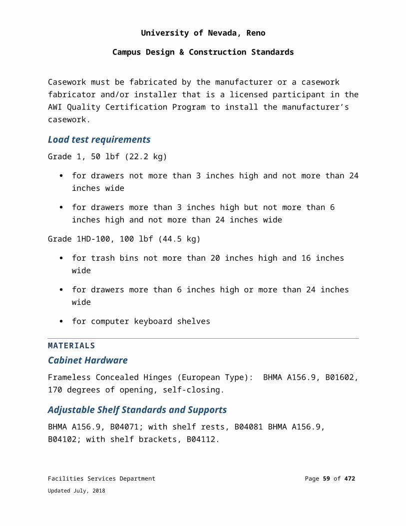
University of Nevada, Reno
Campus Design & Construction Standards
Electronic Door LocksSchlage CO-100-CY-70.
088100 - GLAZINGAll exterior windows shall be dual pane; Low “E” insulated glazing.
End of Division 8
OPENINGS
Facilities Services Department Page 59 of 349
Updated July, 2018
University of Nevada, Reno
Campus Design & Construction Standards
DIVISION 9: FINISHES
092900 - GYPSUM WALLBOARD
SYSTEM DESIGN AND PERFORMANCE REQUIREMENTSAll gypsum wall board shall be Type X
A painted finish shall not be used to comply with the requirements for a hard, smooth, non-absorbent surface for shower room, toilet room walls and floors
Wall RenovationRenovation Wall Constructed Underneath an Existing Ceiling (092116-1)
093013 - TILE
SYSTEM DESIGN AND PERFORMANCE REQUIREMENTSTile floors larger than 10’-0” in any direction shall have relief joints not to exceed 10’-0” on center
All tile flooring and grouting shall be sealed using a water emulsion, acrylic sealer with a minimum 18% non-evaporative solids
The following tile is not to be used due to staining problems:
Bedrosians Tile and Stone
Item Code: TCRRUN36A
Collection: Runway
Color: Alabaster
Size: 12” x 24”
095100 - ACOUSTICAL TREATMENT
SYSTEM DESIGN AND PERFORMANCE REQUIREMENTS
Facilities Services Department Page 60 of 349
Updated July, 2018
University of Nevada, Reno
Campus Design & Construction Standards
Acoustical Tile CeilingsAll ceilings shall be designed to resist earthquakes and have minimum height of 8’-0”
The ceiling grid for suspended ceilings shall be white steel Heavy duty. Ceiling suspension systems shall meet all requirements of 2012 IBC 808
Acoustic Wall Panels7PCF glass fiber core with 16-20PCF tackable glass fiberboard laminated to front, full fabric wrap. Thickness, ¾” min. 1” preferred.
Chemically hardened edge treatment on all panels. Edge detail to be coordinated per project requirements. Mounting using mechanical clips. Core Material is glass fiber with resin hardened edges
NRC 0.95
Comply with ASTM D 5034 Tensile, ASTM D 2261 Tear, Colorfastness AATCC 16E, Flammability ASTM E 84 Class A, NFPA 701
PRODUCT STANDARDS AND MANUFACTURERSAcoustical Tile CeilingsStandard Acoustical Ceiling Tile: Ceiling Tile – Armstrong: Cortega Finish; 15” / 16” Angled Tegular, Medium Texture, 704A (24 X 24 X 5/8) or 703B (24 X 48 x 5/8) and 769A (24 x 48 X 5/8) Square Lay-In. Fire rating Class A
Clean Room Ceiling Tile: Armstrong: Optima 15” / 16” Square lay-in, Fine texture, 3114 (2 X 2) or 3115 (2 x 4). Clean Room Suspension System. Fire rating Class A
Acoustical Wall PanelsCONWED – “ACT Absorptive” sound panels or equal
Panel fabric, Guilford of Maine FR 701
096500 - RESILIENT FLOORING
SYSTEM DESIGN AND PERFORMANCE REQUIREMENTS
Facilities Services Department Page 61 of 349
Updated July, 2018
University of Nevada, Reno
Campus Design & Construction Standards
General Notes for all resilient flooringAll flooring must be asbestos free
Contractor/ Sub-contractor shall purchase and install
Must have 5 years of experience with specified flooring and installation
VCT (12”x12”)Wear Rating: Commercial
Thickness: 0.125” overall
Product Attribute: limestone, polyvinyl chloride resin, plasticizer, stabilizers and pigments
Color Selection: Depending on building and floor; to be approved by Facilities
Smoke Density: Less than 450 when tested in accordance with ASTM E662
Fire Resistance: Flammability minimum of Class1, type A rating per ASTM E648
Static Load Limit: 125 psi in accordance with ATMS F970 should be protected from sharp-point loads and heavy static loads.
Static Coefficient of Friction: 0.05 or > polished slip resistance requirements of OSHA ASTM D2047 James slip test
Light Reflectivity: 65-69%
Maintenance: Sweep, dust mop and/or damp mop floor. If needed seal and wax VCT with a certified janitorial service, recommend ABM Janitorial Service (775) 823-9090 or Service Solution (775) 784-4656. Sweep thoroughly, wash with low PH cleaner, rinse thoroughly, let dry. Seal floor with one coat sealer (factory recommended) let dry. Apply three coats wax (factory recommended): let dry 30 minutes between coats
Warranties: 5 year minimum/ free of charge, similar flooring to replace defective material
Recyclable: 20% Post consumer recyclability min
Method of installation: use manufactures specification installation standard: using non-flammable, low VOC, thin spread adhesive
Facilities Services Department Page 62 of 349
Updated July, 2018
University of Nevada, Reno
Campus Design & Construction Standards
Quartz Tile (24”x24”)Wear Rating: Heavy duty commercial according to EN649
Thickness: 0.10”
Product Attributes: Homogeneous combination of high quality vinyl, calcium carbonate, and fine and naturally weathered quartz. Ensures that color, chipping and marbling will not wear through
Color Selection: Depending on building and floor; to be approved by Facilities
Chemical Resistance: Quartz tile needs to be virtually unaffected by surface water and most chemicals
Light Resistance: Meets light resistance requirements of ASTM F1066
Flexibility: Meet flexibility requirements of ASTM F1066 will not crack or break under pressure
Smoke Density: Less than 450 when tested in accordance with ASTM E662
Fire Resistance: Flammability minimum of Class 1 Type A rating per ASTM E648
Indentation Resistance/ Static Load: Meets the current residual indentation requirements and reaches 2100psi when tested according to ASTM F970
Static Coefficient of Friction: 0.05 or > polished slip resistance requirements of OSHA ASTM D2047 James slip test
Moisture Testing: Moisture emission from concrete subfloors must not exceed 5 lbs. per 100sf per 24 hours- ASTM F1869 and not to exceed 85% internal concrete relative humidity – ASTM F217-02
Maintenance: Dry maintenance method: remove all surface soil, debris, sand and grit by sweeping or dust mopping. Damp mop off any dried on spillages. Do not flood floor. Do not use solvents. Do not wax
Warranties: 15 year minimum/ free of charge, similar flooring to replace defective material
Recyclable: 30% pre-consumer recycled content
Facilities Services Department Page 63 of 349
Updated July, 2018

University of Nevada, Reno
Campus Design & Construction Standards
ISO 14001certified
Green Label certified
LUXURY VINYL Tile (LVT) – Tile and Plank FORMATConstruction: Beveled Edge Preferred, Plank to be approved by Facilities
Wearlayer Thickness: 30 Mil is preferred, no less than 20 mil to be specified. If 20 mil is specified, selection for application must be approved by Facilities
Thickness: 0.098” (2.5 mm)
Product Attributes: Modular flexibility, including large format shapes and sizes, durable, long-lasting performance – withstands heavy foot and rolling load traffic, installation possible over existing flooring containing materials in need of abatement without disruption
Color Selection: Depending on building and floor; to be approved by Facilities
Stain and Chemical Resistance: Must meet or exceed ASTM F-925
Flexibility: Meet flexibility requirements of ASTM F1700
Smoke Density: Less than 450 when tested in accordance with ASTM E662
Fire Resistance: Flammability minimum of Class 1 Type A rating per ASTM E648
Static Load Limit: Must meet or exceed 1000 PSI
Maintenance: Dry maintenance method: remove all surface soil, debris, sand and grit by sweeping or dust mopping. Damp mop off any dried on spillages. Do not flood floor. Do not use solvents. Do not wax
Warranties: 20 year minimum finish warranty - free of charge, exception may be made for 20 mil specification
Method of installation: Use manufactures specification installation standards: Install flooring with adhesives, tools and procedures in strict accordance with the manufacturer’s instructions.
Facilities Services Department Page 64 of 349
Updated July, 2018

University of Nevada, Reno
Campus Design & Construction Standards
Rubber Flooring and Stair CoveringsWear Rating: Relative Resistance to wear of unglazed ceramic tile by the Taber abrader test- ASTM C501
Thickness: 0.125 inch
Product Attribute: 46% rubber content, Self-waxing
Color Selection: Depending on building and floor. To be approved by facilities
Applicable standards: ASTM F-1344, Class 1A
Indentation resistance: ASTM F-970 .000” residual indent at 250 PSI
Flam resistance: ASTM E-648, Class 1
Surface burning characteristics: Must pass the Steiner tunnel test ASTM E84
Static Coefficient of Friction: Greater than 0.85
Stair Treads: ASTM F2169, Type TS, Class 2, Style 1 & 2
Striping: Provide striping for the visually impaired Riser Height: 7 inches ASTM F2169, Type TS, Group 1, Style 1 and 2 Tread Depth: Round, Square or Sculpted (hammered) 12 inches Must use nose filling
Maintenance: Thorough sweep with broom/ Mop with warm water
Warranties:
10 year minimum/ free of charge, similar flooring to replace defective material 10 year warranty against nose cracking using proper nosing filler 10 year limited warranty that the flooring will not wear through raised design
Recyclable: 7% recycled content and can contribute to LEED qualification points
Rubber flooring and stair coverings must be manufactured within 750 miles of job site.
Method of installation: use manufactures specification standards: using non-flammable and low VOC adhesive. Adhesive may vary for tread application.
Facilities Services Department Page 65 of 349
Updated July, 2018
University of Nevada, Reno
Campus Design & Construction Standards
Sheet VinylWear Rating: Commercial
Heat welds are required at all seams
Needs to be verified and approved by Facilities Services project coordinator
Warranties: 15 years minimum/ free of charge, similar flooring to replace defective material commencing on date of substantial completion
Epoxy FlooringWear Rating: Heavy Duty Commercial
Needs to be verified and approved by Facilities Services project coordinator
Warranties: Manufacturer shall furnish a single, written warranty covering both material and workmanship for a period of one full year from date of installation
MMA FlooringWear Rating: Heavy Duty Commercial
Needs to be verified and approved by Facilities Services project coordinator
Warranties: Manufacturer shall furnish a single, written warranty covering both material and workmanship for a period of one full year from date of installation
TileWear Rating: Commercial
Needs to be verified and approved by Facilities Services project coordinator
Installation: Seal floors and grout as per factory recommendations
Warranties: 3 year minimum/free of charge, similar flooring to replace defective material
PRODUCT STANDARDS AND MANUFACTURERSVCT (12”x12”)
Acceptable Manufacturers: Azrock Armstrong
Facilities Services Department Page 66 of 349
Updated July, 2018
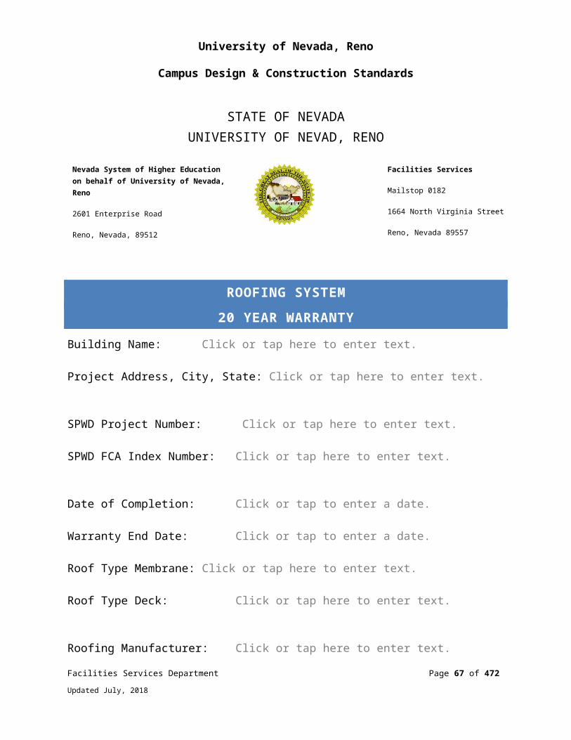
University of Nevada, Reno
Campus Design & Construction Standards
Mannington
Quartz Tile (24”x24”) Acceptable Manufacturers: Altro
Luxury Vinyl Tile (LVT) Acceptable Manufacturers: Mannington Mohawk Interface Shaw Armstrong
Epoxy FlooringFor mechanical room floors or any floors where waterproofing is required, the following products are approved:
BASF Chemical Sonoguard Polyurethane 707 18 00 Color and Sheen to be reviewed and approved by Facilities Services Corotech Water Amine Epoxy V440 Color and Sheen to be reviewed and approved by UNR – Facilities Services Pittsburgh Paints AquaPon WB Epoxy 98 Series Color and Sheen to be reviewed and approved by UNR - Facilities Services
096513 - RESILIENT BASE
SYSTEM DESIGN AND PERFORMANCE REQUIREMENTSHeight: 4-8 inches
Rubber to be SBR vulcanized and thermoset molded with coved toe and rounded top
Provide in 4 foot lengths with pre-molded thermoset outside corners
Facilities Services Department Page 67 of 349
Updated July, 2018

University of Nevada, Reno
Campus Design & Construction Standards
For remodeling project, if existing wood base is acceptable, rubber base may be omitted. Otherwise, existing wood base shall be completely removed and the wall surface patched for application of rubber base or new wood base shall be provided
Adhesive: solvent free no VOC as recommended by manufacturer
Color: To be approved by Facilities
096800 - CARPETING
SYSTEM DESIGN AND PERFORMANCE REQUIREMENTSGeneral Use Carpet (Carpet Tiles and Broadloom) Carpet tiles shall be used to the greatest extent possible. Use of broadloom carpet shall be used only upon approval by Facilities Services
Wear Rating: Heavy or Extra Heavy Commercial: Vetterman Drum wear test- Rating of 3 or better DIN 54323- ISO-TR 10361
Face Weight Carpet Tile - 16 oz. minimum
Broadloom - 20 oz. minimum
Face Yarn 100% first quality bulk continuous filament (BCF).
Acceptable specifications: Type 6,6 nylon or a blended fiber with a minimum of 80% Type 6,6 nylon combined with polymer made from renewable resources or Type 6 with inherent stain resistance by means of cationic dye process. Construction to be approved by Facilities Services based on flooring application.
Acceptable Commercial Fiber Shapes for optimum soil hiding capability
Facilities Services Department Page 68 of 349
Updated July, 2018
University of Nevada, Reno
Campus Design & Construction Standards
Fiber identification at AATTCC 20 test method
Modification ration of 1.7 or less
Dye Method: 100% Solution Dyed
Gauge: 1/8” min
Construction: Tufted
Surface/Style: Level Loop or Multi Level Loop – utilitarian application specifications to be all loop unless otherwise approved by Facilities Services
Color: Depending on building and floor: To be approved by Facilities Services. In refurbishments which do not affect full building renovations Facilities Services to provide Architect of Record with specification information
Density Factor: 5,000 min.
TARR rating: at least 3.0
Stain Resistance: Stain resistance properties MUST be inherent. Topical Stain resistance treatment will not be acceptable. Stain Resistance properties must be permanent and cannot be removed by commercial cleaning or abrasive wear. Must pass the AATCC 175 red dye 40 test. Carpet will retain permanent stain protection against acid type spill for the life of the carpet as measured by General Services Administration (GSA) test for permanence SIN 31-8.
Facilities Services Department Page 69 of 349
Updated July, 2018
University of Nevada, Reno
Campus Design & Construction Standards
Edge Ravel: Limited lifetime Warranty against Edge Ravel. Preference will be given to carpet manufacturers that do NOT require the edges of the carpet to be seam sealed to guarantee 20 years of edge unraveling
Tuft Bind: Wet: Limited Lifetime Warranty against zippering
Color fastness-light/color: Carpet will resist color loss from light exposure for 10 years. Manufacturer to provide a 10 year warranty for colorfastness after exposure to light as measured by AATCC Test Method 16E- International Gray scale rating after 160 AFU’s should be 4 or better
Colorfastness-ozone: Carpet will resist color loss from Atmospheric Contamination for 10 years. Carpet manufacturer to provide a 10 year warranty for colorfastness after exposure to atmospheric contaminates as measured by AATCC Test Method 129- Ozone minimum shade change rating after five cycles should be no less than International Gray scale rating of 4 or better.
Colorfastness-crocking: 4 or better (wet and dry) AATCC transference scale AATCC 165.
Colorfastness- Carpet will resist color transfer from wear for the life of the carpet. Carpet will exhibit permanent colorfastness (wet or dry) for the lifetime of the installation as measured by AATCC Test method 8, minimum stain rating of 4 or better compared to AATCC color transference scale. The carpet will also exhibit permanent wetfastness for the lifetime of the installation as measured by AATCC Test Method 107, minimum shade change should be no less than International Gray Scale rating of 4 or better.
Water: 4 or better AATCC transference scale AATCC 107
Flammability NBS smoke: <450 flaming mode NFPA 258
Flammability Radiant Panel:
Class 1 fire rated ASTM E-648 Class A fire rated ASTM E-84
Static: 3.0 or less AATCC 134 Step method
Maintenance: Pre-treat & hot water extraction cleaning
Warranties: 10 year minimum, with lifetime of carpet for:
Facilities Services Department Page 70 of 349
Updated July, 2018

University of Nevada, Reno
Campus Design & Construction Standards
Wear, no more than 10% face yarn loss Static Edge Ravel Delimitation Tuft Bind, no zipper, wet or dry Stain Resistance
Indoor Air Quality: Meet the Carpet & Rug Institute’s IAQ certification ASTM- D-5116
Recyclable: 20% Post consumer recyclability min. total weight
CRI Green Label Plus certified
BackingBroadloom
Primary: 100% Polypropylene
Preferred Bonding Agent: Hot Melt thermoplastic
Facilities will consider Cross linked Polymer for the bonding agent depending on location and application
Secondary: 100% woven Polypropylene Warranty: Lifetime
TileReinforced synthetic, Bonding Agent: premium vinyl
Fiberglass reinforced Thermoplastic composite
Backing Delimitation: Secondary backing products, 3.5 pounds
Dimensional stability: removable modular products 0.2% or less ISO 2551
Method of installation: Adhesive must be from the same manufacturer as the carpet tile itself.
Tile size: standard square or plank
Warranty: Lifetime
Facilities Services Department Page 71 of 349
Updated July, 2018
University of Nevada, Reno
Campus Design & Construction Standards
Note: ONLY Dormitories and the President’s Office can vary from these performance specifications and it MUST be approved by Facilities Management
Contractor/Sub-contractorMUST purchase and install the carpet
MUST have 5 years of experience with specified carpet and installation
MUST be certified within the last 5 years by the carpet manufacture
099100 - PAINTING
PRODUCT STANDARDS AND MANUFACTURERSInterior Walls (includes classrooms, hallways, offices, stairways, restrooms, etc.)
Benjamin Moore Paints Eco Spec Interior Semi-gloss Latex 376 Color and sheen to be reviewed and approved by UNR Facilities Services Benjamin Moore Ultra Spec 500 N540 Color and sheen to be reviewed and approved by UNR Facilities Services
Durable Wall FinishFor areas that require a more durable wall finish to moisture or sanitation issues such as shower rooms, kitchens, food services, or specialty labs
Pittsburgh Paints AquaPon WB Epoxy 98 Series Color and sheen to be reviewed and approved by UNR Facilities Services
Interior and Exterior (includes doors, door trim, safety railings, exterior stairways, handrails)
Pittsburgh Paints Pitt Tech DTM Industrial Acrylic Enamel 90 Series
Facilities Services Department Page 72 of 349
Updated July, 2018

University of Nevada, Reno
Campus Design & Construction Standards
Color and sheen to be reviewed and approved by UNR Facilities Services PPG Industrial Finishes Durathane 95-3300 Color: To be reviewed and approved by UNR Facilities Services
Floor Paints (for normal foot traffic and light duty services)
Pittsburgh Paints AquaPon WB Epoxy 98 Series Color and sheen to be reviewed and approved by UNR Facilities Services
Floor Paints for heavy-duty service and extreme traffic areas product should be project specific.
Mechanical Room Floors (or any floors where waterproofing is required)
BASF Chemical Sonoguard Polyurethane 707 18 00 Color and Sheen to be reviewed and approved by UNR –Facilities Services Corotech Water Amine Epoxy V440 Color and Sheen to be reviewed and approved by UNR – Facilities Services Pittsburgh Paints AquaPon WB Epoxy 98 Series Color and Sheen to be reviewed and approved by UNR –Facilities Services
Standard University Colors UNR Off White UNR Blue UNR Gray Bronzetone Hemlock Green BM 969 Soft Chamois
Facilities Services Department Page 73 of 349
Updated July, 2018
University of Nevada, Reno
Campus Design & Construction Standards
Color samples/information for standard UNR colors are available at:
Facilities Services Department: 784-6514
UNR Paint Shop: 784-8036
End of Division 9
FINISHES
Facilities Services Department Page 74 of 349
Updated July, 2018
University of Nevada, Reno
Campus Design & Construction Standards
DIVISION 10: SPECIALTIES
101100 - VISUAL DISPLAY UNITS
PRODUCT STANDARDS AND MANUFACTURERSHallway installation is to be done in a manner that allows placement of room numbers adjacent to doorways per APPENDIX I.
Whiteboards4’ X 8’ typical size
24 gauge high gloss on 7/16” Particle Board
Map Rail, Chalk Tray, Satin Aluminum Trim
Approved Manufacturers:
Claridge Series 4 Markerboard, or equal
Tackboards4’ X 3’ typical & 4’ X 6’ typical sizing
¼” cork on ¼” hardboard - Fabric Covering
Satin Aluminum Trim
Approved Manufacturers:
Claridge Series 4 Fabricork Tackboard
Fabricmate acoustic panels
101300 - DIRECTORIES
SYSTEM DESIGN AND PERFORMANCE STANDARDSMain building directory boards shall be mounted within each main entrance to a building.
Facilities Services Department Page 75 of 349
Updated July, 2018
University of Nevada, Reno
Campus Design & Construction Standards
Main directories shall include a listing of each department and a summary of floors and/or rooms occupied by these departments.
Fabricate in strict accordance with the approved shop drawings and the original design, except where specifically otherwise approved by the Architect.
Inspect the areas and conditions under which work of this section will be installed. Correct conditions detrimental to the proper and timely completion of the work. Do not proceed until unsatisfactory conditions have been corrected.
InstallationAt all times during progress of work, coordinate as required with all other trades to ensure proper and adequate provision in the work of other trades for interface with the work required under this section.
Comply with all applicable recommendations of the ADA and ANSI Specification A117.1.
Install the work of this section in strict accordance with the original design and the approved shop drawings, except as specifically otherwise approved by the Architect. Anchor all components firmly into position, in the true alignment horizontally and vertically within a tolerance of one in 1000.
PRODUCT STANDARDS AND MANUFACTURERSBuilding Directories (Removable Letter)Subject to compliance with requirements, manufacturers offering signage that may be incorporated in the work include, but are not limited to the following:
Claridge Products and Equipment, Inc.
Approved equal
Materials
Directory type: No. 546 (Claridge) Frame finish: No. 314p Bronze Panel type: Grooved Felt, 1/4” on center Panel Color: Gray Glass: Clear 3/16” tempered
Facilities Services Department Page 76 of 349
Updated July, 2018
University of Nevada, Reno
Campus Design & Construction Standards
Lockset: Flat key tumbler Hinges: Continuous Piano Mounting: Surface with concealed hangers Size: 24” x 36” Lettering: Roman Style molded white plastic letters with storage box, No. 385 &
No. 386
Building Directories (Printed Surface)Subject to compliance with requirements, manufacturers offering signage which may be incorporated in the work include, but are not limited to the following:
Norwood Commercial Furniture/Ghent Approved equal
Directory Materials:
Directory type: SKU: NOR-ATA-1000-SO/Ghent PA13624VX Frame finish: Anodized aluminum Surface: Natural cork Window Material: Shatter-resistant clear acrylic Usage: Outdoor/indoor Width: 2’ Height: 3’ Depth: 1-1/2” (interior), 2-1/2” (exterior) Hinges: Continuous piano Lockset: Flat key tumbler
Printed Surface Materials:
Material type: Foam Core board or equivalent Depth: 3/16” Width: 24” (Cut to fit) Height: 36” (Cut to fit)
Content of printed surface to be determined by department(s) with design and printing assistance from UNR Marketing & Communications. Content and design to be approved by the UNR Facilities Resource Committee.
Building Directories (Digital)Subject to compliance with requirements, manufacturers offering signage which may be incorporated in the work include, but are not limited to the following:
Facilities Services Department Page 77 of 349
Updated July, 2018
University of Nevada, Reno
Campus Design & Construction Standards
Sharp Professional LED Displays (PN-YXXX5 model line) Approved equal (only with express written approval by Teaching and Learning
Technologies (TLT))
Directory Materials/Features:
Sharp Commercial flat panel displays (Sharp PN-Y43625) Screen size: Size as determined by UNR TLT; default is 42” class Monitor: Commercial grade flat panel Warranty: 3 years parts and& labor
Directory Installation Requirements:
Power: 20A 120V Duplex Data: Requires data drop to connect to UNR network. Compliance: All work to comply with 2011 NEC & UNR Construction standards.
Directory Flat Panel Mounts:
Manufacturer: Premier Mounts Model: Low Profile Portrait Mount (P4263FP)
Other MaterialsAll other materials not specifically described, but required for a complete and proper installation, shall be as selected by the Contractor subject to the approval of the Architect.
101400 - SIGNAGE
SYSTEM DESIGN AND PERFORMANCE STANDARDSFire Wall Barrier Signs, Fire Wall LabelingProvide permanent identification, with signs or stenciling, of all fire walls, fire barriers, fire partitions and smoke barriers that are required to have protected openings or penetrations.
Each identification will be located within 15 feet of the end of each wall and include lettering not less than 3 inches high per Section 707.6 IBC.
See SECTION 3.0 GENERAL CAMPUS SIGNAGE POLICY AND STANDARDS for additional information regarding signage.
Facilities Services Department Page 78 of 349
Updated July, 2018

University of Nevada, Reno
Campus Design & Construction Standards
See APPENDIX I for additional information regarding interior signage, materials, and layout.
Provide all identifying devices complete, in place, specified herein, and as needed for a complete and proper installation.
Exterior Wayfinding SignageTypical ADA Flag Sign Detail (101426-1)Parking - Traffic Sign Detail
Lettering on Glass DoorsSpecial circumstances may warrant lettering on glass doors and adjacent glass. This shall have the approval of the Facilities Services Department. Lettering shall be gold metallic with a black shadow or white in decal form and be applied directly to the glass by an approved vendor. The size and layout of the lettering will be determined by the size of the door glass but not to exceed four inches in height unless it is an official building number, which is typically 6 inches in height.
PRODUCT STANDARDS AND MANUFACTURERSProducts used in the work of this section shall be produced by manufacturers regularly engaged in manufacture of similar items.
Use adequate numbers of skilled workers who are thoroughly trained and experienced in the necessary crafts and who are completely familiar with the specified requirements and the methods needed for proper performance of the work of this section.
101419 - EXTERIOR DIMENSIONAL LETTER SIGNAGE
SYSTEM DESIGN AND PERFORMANCE STANDARDSSignage mounted to the exterior of the buildings shall be cast aluminum lettering, not panel signs.
Variances to size, finish and font style of any exterior building lettering needs to be pre-approved by Facilities Services and the Facilities Resource Committee.
See APPENDIX I for typical lettering details.
Facilities Services Department Page 79 of 349
Updated July, 2018

University of Nevada, Reno
Campus Design & Construction Standards
PRODUCT STANDARDS AND MANUFACTURERSUse all means necessary to protect materials of this section before, during, and after installation and to protect installed work and materials of all other trades.
In the event of damage, immediately make all repairs and replacements necessary to the approval of the Architect and at no additional cost to the Owner.
101423 - INTERIOR PANEL SIGNAGE
SYSTEM DESIGN AND PERFORMANCE STANDARDSSee APPENDIX I for interior signage requirements for new construction and existing buildings.
Typical Room SignageHistorical: 1/8” acrylic with 1/32” raised extended acrylic letters and symbols with braille per ADA and ANSI A117.1 requirements, extruded aluminum frame
New Construction: Perforated brushed finished chassis with placard
MountingMechanically Fastened
Pictograms6” x 8” Pictograms shall use International Symbols. All signage shall comply with the ADA for size, image and raised braille.
Emergency LED Exit SignsProvide LED lighted exit signs for marking the means of egress in accordance with Life Safety Code NFPA 101.
Signs shall have green letters with LED lamps and battery backup.
Use dual-voltage input 120v or 277V AC.
Provide with test switch, status indicator, and rechargeable maintenance.
Facilities Services Department Page 80 of 349
Updated July, 2018
University of Nevada, Reno
Campus Design & Construction Standards
Exit Plan Signage Systems shall be designed using the following specifications
Frame type: Custom, extruded aluminum frame, 3/4” wide Frame finish: Anodized, Medium Bronze Glass: Clear 3/16” tempered Mounting: Surface with concealed hangers Size: 11” x 17”
Appropriate interior graphics and signage complying with adopted barrier-free design standards shall be included in all buildings.
PRODUCT STANDARDS AND MANUFACTURERSSubject to compliance with requirements, manufacturers offering signage that may be incorporated in the work include, but are not limited to, the following:
ASI Sign Systems Art Images Tripp Plastics Approved equal
101716 - TELEPHONE ENCLOSURES (EMERGENCY BLUE LIGHT TELEPHONE)
SYSTEM DESIGN AND PERFORMANCE STANDARDSExterior Emergency Phone TowerConsist of a highly vandal-resistant freestanding steel emergency phone tower mount with an integrated flashing LED blue light.
Have an integrated LED faceplate light, mounted directly above the phone faceplate.
Tower to be safety blue in color with highly reflective white “EMERGENCY” lettering.
Exterior Emergency Phone for Tower ApplicationOutdoor, two-button, ADA-compliant phone with LED indicator.
Phone line powered with built-in two-line autodialer. Hands free after initial push.
Two buttons, one for Emergency (911), the other programmable for information or a police duty phone. Programmable to situation.
Facilities Services Department Page 81 of 349
Updated July, 2018
University of Nevada, Reno
Campus Design & Construction Standards
Exterior Building Mount Emergency PhoneOutdoor, one-button, ADA-compliant phone with LED indicator.
Phone line powered with built-in two-line autodialer. Hands free after initial push.
Two buttons, one for Emergency (911) or to Call for police duty phone. Programmable to situation.
Auxiliary input and outputs programmable to integrate with CCTV, Blue Light/Strobe, etc.
Parking Structure Emergency PhoneOutdoor, one-button, ADA-compliant phone with LED indicator.
Phone line powered with built-in two-line autodialer. Hands free after initial push.
One button for Emergency (911). Programmable to situation.
Auxiliary input and outputs programmable to integrate with CCTV, blue Light/strobe, etc.
PRODUCT STANDARDS AND MANUFACTURERSExterior Emergency Phone TowerTalk-A-Phone; Model ETP-MT
There are no equivalents.
Exterior Emergency Phone for Tower ApplicationTalk-A-Phone; Model ETP-500E (1 button) or ETP-500EI (2button)
There are no equivalents.
Exterior Building Mount Emergency PhoneTalk-A-Phone; Model ETP-WM
There are no equivalents.
Parking Structure Emergency PhoneTalk-A-Phone; Model ETP-500E
Facilities Services Department Page 82 of 349
Updated July, 2018
University of Nevada, Reno
Campus Design & Construction Standards
There are no equivalents.
Typical Blue Light Phone Installation (101716, drawing mislabeled 273523-1)
102113 - SOLID PLASTIC TOILET COMPARTMENTS
SYSTEM DESIGN AND PERFORMANCE STANDARDSProvide Solid Core Reinforced Composite (SCRC) 1092.67P partitions and shower enclosures.
Floor-mounted, overhead braced toilet compartments with non-corrosive components made of 3/4” doors and stiles and ½” panels of SCRC.
The supporting hardware to be 18-8 type 304 stainless steel with satin finish.
Threaded inserts shall be factory installed for door hinge and latch to withstand direct pull force exceeding 1,500 pounds per fastener. Hardware of chrome plated Zamak, aluminum, or extruded plastic is unacceptable.
Mounting brackets shall be 18 gauge stainless steel and extend the full height of panel.
Leveling device shall be 7 gauge, 3/16”, hot rolled steel bar, chromate treated.
Stile shoe shall be one piece, 4” high, type 304 stainless steel with satin finish.
Wall-mounted urinal screens shall be SCRC 1095 with 11 gauge stainless steel mounting brackets.
PRODUCT STANDARDS AND MANUFACTURERSHigh-density polyethylene is more durable than other materials, is non-absorptive, resists moisture, odors and mildew, and graffiti. The material does not rust or need painting. Provide 15-year warranty on all materials.Comply with ASTM standards
Impact resistance ASTM D 2794-93 Min. 34 inch-lbs.
Scratch resistance ASTM D 2179-98 Min. 10.0 kg.
Graffiti resistance ASTM D 6578-00
ASTM E 84 Flame spread index 45
Facilities Services Department Page 83 of 349
Updated July, 2018

University of Nevada, Reno
Campus Design & Construction Standards
ASTM E 84 Smoke spread index 120
Toilet partitions constructed of HDPE or color-thru phenolic will not be acceptable.
Acceptable Manufacturers
Privacy Plus toilet compartments by Gerali Custom Design
Wilson Art Gibraltar Material
Wilson Art Earthstone Material
02813 - TOILET AND BATH ACCESSORIES
PRODUCT STANDARDS AND MANUFACTURERSInstallation of accessories must be compliant with ADA codes and regulations including cane detection as appropriate.
Waste Receptacles shall be 25 gallon capacity, 11” wide x 30”high x 20”long, gray in color, swing lid. 3540 Slim Jim Waste Container by Rubbermaid. Rubbermaid FG354000 Gray, 2673-60 Slim Jim Swing Lid, FG267360 Gray.
Mirror with Stainless Steel ChanNel FrameType-430 stainless steel, ½” x ½” x 3/8” (13 x 13 x 9.5mm) channel with ¼” (6mm) return at rear with bright polished finish. No. 1 quality, ¼” (6mm) select float glass: selected for silvering, electrolytically copper-plated by the galvanic process, and guaranteed for 10 years against silver spoilage. 20 gauge (0.9mm) galvanized steel. Incorporates lower support member, forming rigid rectangle, which engages lower back-plate louver to keep bottom of mirror against wall. Bobrick B-165 Series.
Coat Hook with BumperSolid cast aluminum with matte finish, hard rubber secured with drive screw, wall unit mounted with four screws. Bobrick B-212.
Toilet Seat Cover DispenserFor dispensing ½ or single fold seat covers with 250 seat covers capacity, 18-8S, type-304, 22-gauge (0.8mm) stainless steel with satin finish. Bobrick B-221.
Facilities Services Department Page 84 of 349
Updated July, 2018
University of Nevada, Reno
Campus Design & Construction Standards
Utility ShelfKeep mops and brooms away from wall, spring-loaded rubber cam holders, and utility shelf shall all be type-304 stainless steel with satin finish on exposed surfaces. 8” (205mm) deep with ¾” (19mm) return edges. Bobrick B-239
Sanitary Napkin DisposalSelf-closing panel covering disposal opening, wall type, heavy-gauge stainless steel. Use Bobrick B-254 in non-ADA stalls. Use comparable ADA compliant devices in ADA stalls.
Diaper Changing StationHigh impact gray polyethylene with foam core, surface-mounted on wall or semi-recessed into wall opening 2-1/2” (65mm) deep, pneumatic cylinder for slow controlled opening. Bobrick KB-200-01.
GRAB BARS¼” (32mm) diameter, stainless steel, snap flange. Bobrick B-5806 Series.
OWNER SUPPLIED/CONTRACTOR INSTALLED EQUIPMENTPaper Towel DispenserSurface mounted paper towel dispenser (Splash Blue or Smoke Grey). Georgia-Pacific enMotion Automated Towel Dispenser, Mfg. #59460 or 59462.
Toilet Tissue DispenserSurface mounted multi-roll toilet tissue dispenser (Splash Blue/Translucent Smoke). Georgia-Pacific compact quad vertical four roll coreless tissue dispenser. Mfg. #56743 or 56744.
Soap DispenserSurface mounted Automatic Touchless Soap Dispenser (Splash Blue/Smoke). Georgia-Pacific Mfg. # 52053 or 52052.
104413 - FIRE PROTECTION CABINETS
SYSTEM DESIGN AND PERFORMANCE STANDARDS
Facilities Services Department Page 85 of 349
Updated July, 2018
University of Nevada, Reno
Campus Design & Construction Standards
All fire extinguisher cabinets may be of recessed, semi recessed, or surface mount design.
Cabinets must be suitable for all conditions within their mounted locations.
Cabinets must contain a full acrylic or non-wire imbedded glass front and be of only pull handle and roller catch design.
All fire extinguisher cabinets shall be latch closure, non-locking type.
Locking cabinets for exterior installations only will only be permitted upon design review of their intended location.
Extinguishers and cabinets shall be clearly labeled as to their location on plans.
104416 - FIRE EXTINGUISHERS
PRODUCT STANDARDS AND MANUFACTURERSAll CO2 type extinguishers shall be no larger than 10 lb. unless specifically called for and approved by UNR Facilities Services.
All UNR fire extinguishers shall be Amerex brand.
10850 - KNOX BOX
SYSTEM DESIGN AND PERFORMANCE STANDARDSProvide a Knox Box at each building to accommodate fire department access.
All Knox Boxes to be dual keyed.
Flush mount, ¼” thick plate steel housing, 5/8” thick steel door with interior gasket seal and stainless steel hinge, and tamper-resistant fasteners. Finish to be selected by Architect and Owner.
Coordinate placement with Fire Department authorization.
Coordinate mounting height and location in field with the Architect and Owner.
PRODUCT STANDARDS AND MANUFACTURERS
Facilities Services Department Page 86 of 349
Updated July, 2018

University of Nevada, Reno
Campus Design & Construction Standards
Large Size Knox Box: Use Knox Box Model # 1300 Series for all buildings that need keys and HazMat Binders to be housed in the Knox Box.
Standard Knox Box: Use Knox Box # 4100 Series or # 4400 Series for buildings that require only keys to be housed in the Knox Box.
Manufacturer:
Knox Company1601 W. Deer Valley RoadPhoenix, AZ 85027(800) 552-5669
End of Division 10
SPECIALTIES
Facilities Services Department Page 87 of 349
Updated July, 2018

University of Nevada, Reno
Campus Design & Construction Standards
DIVISION 11: EQUIPMENT
115313 - FUME HOODS
SYSTEM DESIGN AND PERFORMANCE REQUIREMENTSAll newly installed hoods shall be equipped with a flow indicator, flow alarm, or face velocity alarm indicator to alert users of improper exhaust flow.
The flow measuring device shall be capable of indicating that the air flow is in the desired range, and capable of indicating improper flow when the flow is high or low by 20% (ANSI Z9.2-2012 section 3.3.3).
Fume hoods shall be designed to maintain an average face velocity between 80 fpm and 120 fpm at the design sash position of 16” with no individual face velocity measurement exceeding +/- 20% of the hoods average velocity. (ANSI Z9.5 – 2012 section 3.3.1)
Diversity The following must be considered when applying the concept of ventilation and load diversity:
Capacity of any existing equipment
Expansion considerations
Maintenance department’s ability to perform periodic maintenance
Minimum and maximum ventilation rates for each laboratory
Quantity of hoods and researchers
Requirements to maintain a minimum exhaust volume for each hood on the system
Sash management (sash habits of users)
Thermal loads
Type, size, and operating times of facility
Type of laboratory chemical hood controls
Facilities Services Department Page 88 of 349
Updated July, 2018
University of Nevada, Reno
Campus Design & Construction Standards
Use patterns of variable volume hoods
Following conditions shall be met in order to design a system diversity:
Acceptance of all hood-use restrictions by the user groups. Designers must take into account the common work practices of the site users
An airflow alarm system must be installed to warn users when the system is operating beyond capabilities allowed by diversity
Restrictions on future expansions or flexibility must be identifies
PRODUCT STANDARDS AND MANUFACTURERSThe following fume hood manufacturers are acceptable for new ducted fume hood installations:
Labconco
Hamilton Scientific
Kewaunee
LECTERNSLectern requirements are located in APPENDIX G, Audio Visual Design Standards.
LABORATORY AND DEIONIZED WATERLaboratory and Deionized Water requirements are located in Division 22, Plumbing.
End of Division 11
EQUIPMENT
Facilities Services Department Page 89 of 349
Updated July, 2018

University of Nevada, Reno
Campus Design & Construction Standards
DIVISION 12: FURNISHINGS
122113 - HORIZONTAL LOUVER BLINDS
PRODUCT STANDARDS AND MANUFACTURERSMini-blinds shall be Levolor (or equal)
Aluminum slats shall be with nominal 1” wide louver slat
Color Options:
Levolor #112 Alabaster Riviera 1” Dustguard
Levolor #885 Dark Bronze Riviera 1” Dustguard
Color Option to be determined by University Facilities Services Department only.
122200 - CURTAINS AND DRAPES
Window drapery and coverings shall be fade resistant and comply with minimum flame spread and smoke generation ratings.
122113 - SOLAR SHADE STANDARD
PRODUCT STANDARDS AND MANUFACTURERS Chain or Motorized Operated
Type 6 Nylon with 3 high strength carbon steel wrap springs
Chain - #10 qualified stainless steel
Brackets – Standard brackets are .125 thick steel ceiling, rear or side mount
Tubes and Spline – Key ways providing for simple field adjustability or changing of fabric bands. Soft PVC Spline is welded onto shade band to affix shade to tube
1 ½ “ tube with single spline key way in .065 gauge wall or 2 ½ “ tube with three spline key ways in .071 gauge wall
Facilities Services Department Page 90 of 349
Updated July, 2018
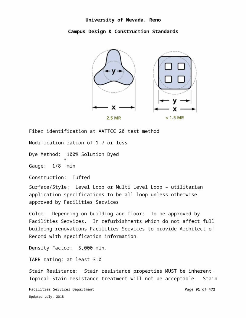
University of Nevada, Reno
Campus Design & Construction Standards
123553 – LABORATORY CASEWORK
SYSTEM DESIGN AND PERFORMANCE REQUIREMENTSCasework must be manufactured, delivered, and installed under the direct supervision of a single manufacturer to ensure a single source of responsibility.
Depending on lab use, select lab casework material on a case-by-case basis.
PRODUCT STANDARDS AND MANUFACTURERSGeneralHardwood: Kiln-dried hardwood, clear and free of defects, maple for exposed components
Plywood: Either veneer core or 3 ply 45lb. particle board core (vertical services and base cabinets’ bottoms only)
Exposed face veneers: Rotary-cut select white hard maple
Melamine Components shall not be allowed
Cabinet ConstructionStyle: Flush overlay door and drawer construction and/or blush overlay. Door and drawer color with radius edges for all sides.
Grain Direction: Vertical match
Cabinet Component ConstructionShelves: ¾” veneer core plywood with edge banding
Doors: Solid door of 3-ply ¾” particle core
Drawers: Four-sided drawer box with ½” 9-ply birch plywood
Lab Tops: Minimum 1” thick epoxy resin lab grade top
HardwareDoor Catches: Adjustable tension nylon roller or magnetic
Facilities Services Department Page 91 of 349
Updated July, 2018
University of Nevada, Reno
Campus Design & Construction Standards
Shelf Supports: Pin and socket style, plated 13 gauge steel angle with 5 mm dia. 3/8” long support pin
Drawer Suspension: ¾ extension, open roller, 100lb dynamic load, epoxy coated
Hinges: 5-knuckle institutional style, stainless steel, or concealed 165 degree self-closing or 3-barrel
Locks: Five disk tumbler, heavy duty cylinder, for master key system
Pulls: Steel wire, in powder coat or plated chrome (satin)
FINISHAll surfaces free of dirt, interior and exterior veneer surfaces exposed after installation to be stained and finished with multiple coats of chemical resistant acrylic urethane finish (including UV blocker).
124813 - ENTRANCE FLOOR MATS AND FRAMES
SYSTEM DESIGN AND PERFORMANCE REQUIREMENTSProvide “walk-off” mats at exterior and interior entrances
Floor mats shall comply with ADA Accessibility Guidelines for Buildings and Facilities
Recessed Frames – Extruded Aluminum ASTM B 221
Wear Rating: Heavy Commercial
125633 - CLASSROOM TABLES AND CHAIRS
SYSTEM DESIGN AND PERFORMANCE REQUIREMENTSClassroom Seating - Stack ChairFlex back for comfort in extended term class applications
Polypropylene shell (for flexibility and durability)
Aesthetic
Color: Warm Grey Shell and Frame
Facilities Services Department Page 92 of 349
Updated July, 2018

University of Nevada, Reno
Campus Design & Construction Standards
Classroom Seating - Task ChairsFlex back for comfort
Polypropylene shell (for flexibility and durability)
Simple function (up and down adjustment)
Ergonomic Task Seating
Aesthetic
Classroom Seating - Tablet ArmFlex back for comfort in extended term class applications
Polypropylene shell (for flexibility and durability)
Oversize tablet arm (plywood core preferred for strength and screw retention)
Aesthetic
Color: Back shell and frame Warm Grey; seat shell Midnight; Laminate White Nebula
Standard and Oversized Tablet Boards are 5/8” high-density particleboard with melamine laminate surface. Limited laminate colors. Edge is painted to match laminate
Laptop Size Tablet Boards are 5/8”, 11-ply plywood core with high pressure laminate and plain backer sheet
Tablet Arm DimensionsStandard Size: 12-1/2” x 20-1/2”
Oversized: 17” x 20-12”
Laptop Size: 19” x 22-3/4”
Classroom TablesFixed leg, standard size 24 x 48 74 “P” edge
Color: Legs Warm Grey
Laminate White Nebula
Facilities Services Department Page 93 of 349
Updated July, 2018
University of Nevada, Reno
Campus Design & Construction Standards
Optional:
Wire management Casters Modesty Panel
Panel shall be 0685” thick particleboard faced on both sides with laminate that matches tabletop laminate: vinyl bullnose will match vinyl bullnose color on top four KI core colors only (black, sand, blue grey, and warm grey). All other tops will have black bullnose on modesty panels as standard. The modesty panel will be available on fixed, folding or flip-top Barron tables. The table top and modesty panel will be pre drilled to accept the modesty panel. The panel is shipped “KD”. The lower edge of the panel will extend 8-1/4” from the underside of the table.
Tops: All tops SHALL be pre drilled. Vinyl “T” molding shall be press fit into particleboard core. Nails will secure molding to top. There will be 7-1/6” spike on “T” molding. There will be 15 standard vinyl edge colors in 1-1/4” (54B edge) size: Black*, Blue Grey*, Warm Grey*, Sand*, Eggshell White*, Light Tone*, Yellow, Cobalt Blue, Juniper, Marsh, Baltic, Midnight, Bordeaux, Plum Stone, Russett, Thistle, Rouge, Teal Green.
Veneer: Surface will consist of 1-1/8” thick high-density particleboard core covered with a 0.30” to 0.50” high pressure melamine laminate top with 0.30 to 0.26 Gatorply back sheet. Wood edges will be of solid red oak lumber with a clear lacquer finish as standard. Option will include maple wood with 4 stain finishes. Radius or square corners. Bullnose edges will be in vinyl with radius corners; self-edges will be with square corners. Beveled edge with bullnose will have dark neutral phenolic backing sheet, which will cover exposed bevel. Exposed wood will be protected by a conversion catalyzed lacquer.
Resin: Resin will be 1-1/8” to 1-1/2” high density particleboard core. Resin will be approximately 1/8” thick covering top and edges. Overall will be 1-3/8” thick. Back surfaces will be sealed.
Wire ManagementLeg Wireways: will be scruff resistant, high impact, rigid PVC, plastic with two separate wire channels per leg. Leg wireways will be fastened to the legs using a full-length adhesive bond. Wireways will be available in black only. They will be shipped assembled. There will be one wireway per leg.
Facilities Services Department Page 94 of 349
Updated July, 2018
University of Nevada, Reno
Campus Design & Construction Standards
Grommets: Plastic grommets will be 3” in overall diameter and will be recessed into the tabletop. The cap will be fully removable and will have a retractable slot cover. Will be available in four standard colors: Black, Blue Grey, Warm Grey, and Sand. There will be two grommets per top.
Under-Table Wire Harness: will be made of easy to use, high quality black Velcro. Harness will be screwed to the table bottom. Harness will be shipped assembled. Provides organized wire management from tabletop to floor.
Table Truck: Product minimums for the truck will be 48” round or square and 18” x 60” rectangular. Maximum table sized are 48” x 96” rectangular or 60” round or square. Maximum length will be up to 8’ long. Maximum number of Barron folding tables will be six. Overall dimension of the truck will be 30” wide, 60” long and 55” high. Overall weight will be 90lbs. The truck platform will be constructed of 2” x 2” angle iron and the two side rails of 1” diameter x 14-gauge tubing. Two swivel and two rigid 5” diameter casters with heavy-duty roller bearings will permit easy and safe movement on any hard floor surface. Shipment will be in two packages: one with the truck platform and one with the two side rails. Assembly with four thumbscrews will be required.
Chroming: Steel surfaces will be duplex nickel-chrome plated in a twenty-two step process. This process is the same as is used in the automotive industry for exterior finishes.
PRODUCT STANDARDS AND MANUFACTURERSClassroom Seating - Stack ChairUndergoing Reselection
Warranty: 10 years parts and labor
Classroom Seating - Task ChairsUndergoing Reselection
Warranty: 10 years parts and labor
Classroom Seating - Tablet ArmUndergoing Reselection
Warranty: 10 years parts and labor
Facilities Services Department Page 95 of 349
Updated July, 2018
University of Nevada, Reno
Campus Design & Construction Standards
Classroom Tables:Undergoing Reselection
Warranty: 10 years on bases and tops
126100 - FIXED AUDIENCE SEATING
SYSTEM DESIGN AND PERFORMANCE REQUIREMENTSFire Test Response Characteristics of Upholstered Chairs:
Padding: Comply with California Technical Bulletin 117
Certified Wood Materials: Provide seating units made from wood and wood-based materials that are produced from wood obtained from forests certified by an FSC accredited certification body to comply with FSC 1.2, “Principles and Criteria.”
Upholstery Fabric Source Limitations: Obtain fabric of a single dye lot for each color and pattern of fabric required.
Electrical Components, Devices, and Accessories: Listed and labeled as defined in NFPA 70, Article 100, by a testing agency acceptable to authorities having jurisdiction, and marked for intended use.
PRODUCT STANDARDS AND MANUFACTURERSAvailable Products: Subject to compliance with requirements, products that may be incorporated into the work include, but are not limited to, the following products:
KI, Concerto Auditorium SeatingBack cushion assembly: structural back shall be a 7-ply, 7/16” molded plywood inner structure bonded to 2” urethane foam. Foam density shall be 3.2 lbs. per cubic foot.
Seat cushion assembly: compound curve inner structure consisting of a 7-ply, 7/16" molded plywood board with waterfall. The seat board counterbalance shall be bolted in place inside the seat assembly. The seat board shall be bonded to a 2" or 3" urethane foam cushion of 3.2 lbs. density per cubic foot.
Facilities Services Department Page 96 of 349
Updated July, 2018

University of Nevada, Reno
Campus Design & Construction Standards
Tablet ArmLarge tablet arm, shall be a self-storing, one-motion table arm, consisting of a storable writing surface constructed of a 13-ply Baltic Birch plywood core, .040 high-pressure laminate on face and .040 HPL backer sheet, measuring 11 ½” X 15 ¼”.
Seat Pivot AssemblyPivot shall include a full width axle of 5/8” diameter cold-rolled steel, with welded 12-guage drawn steel pivot stop cams and 10-guage formed steel end brackets.
TextileKI fabric or Pallas, durability 60,000 double rubs, upholstery fabric shall be bonded to foam and attached through C-Gex upholstery methods
Molded PlasticHigh density polyethylene, injection-molded
Optional Power/Data ModuleOne distribution harness feeds two seats. Fully enclosed wireway covers. Power/data system shall be UL listed.
Uprights and Chair MountingSeating shall be floor mounted, or riser mounted, with common upright support assemblies. Upright floor mounted shall be 16-gauge steel round dual supports, 1.5” diameter, welded to an 11-gauge steel, 2 5/8” X 10 1/8” floor plate by a concealed weldment. Finish to be powder coated according to standard color offering. Riser mounted uprights shall be 14-gauge steel round dual supports, 1.5” diameter, welded to a 3” X 5 1/5” X 10 ¼” steel riser plate. Finish to be powder coated according to standard color offerings.
129300 - SITE FURNISHINGS
SYSTEM DESIGN AND PERFORMANCE REQUIREMENTSBicycle Racks All major remodel and new construction projects shall address the need for bicycle parking.
Facilities Services Department Page 97 of 349
Updated July, 2018
University of Nevada, Reno
Campus Design & Construction Standards
Racks are intended to accommodate conventional, upright, single-rider bicycles. Assume the cyclist will use a solid, U-shaped lock, or a cable lock, or a combination of the two.
Racks shall not block or inhibit pedestrian flow in or out of buildings. The rack shall be located along a major building approach line and clearly visible from the approach.
Support the bicycle upright by its frame in two places.
Prevent the wheel of the bicycle from tipping over.
Enable the frame and one or both wheels to be secured.
Support bicycles without a diamond-shaped frame with a horizontal top tube.
Allow front-in parking: a U-lock should be able to lock the front wheel and the down tube of an upright bicycle.
Allow back-in parking: a U-lock should be able to lock the rear wheel and seat tube of the bicycle.
Use inverted “U” style rack designs. Wave style racks shall not be used.
Facilities Services Department Page 98 of 349
Updated July, 2018
University of Nevada, Reno
Campus Design & Construction Standards
The rack should provide easy, independent bike access. Inverted “U” rack elements mounted in a row should be placed on 30 inch centers. Allow at least 72 inches of depth for each row of parked bicycles.
Bike racks shall be located in well-lit areas.
Recycling ContainersIn design of remodel and/or new construction projects, space for recycling containers is required.
25 gallon capacity, 11” x 30” x 30” (WxHxL), gray in color, single stream cut lid.
21-3/32" Length x 12-3/32" Width x 5.4" Height single stream recycling top
Outdoor seating and tables, permanently affixed, and left outdoors year-round¼” Plasticol-coating heat-fused and permanently bonded to steel coated with a baked on polyester dry powder, per AAMA 2604-05 test specifications.
Rust and Corrosion Resistance
5- yr. warranty
Flame Resistant
Bench seating with back typical. Framework constructed from 2-3/8” powder-coated steel tubing with diamond, perforated or welded wire pattern. Rolled edging.
Single-Pedestal octagon tables with rolled edge seating. Two, three, and four seat options. Two and three seat options ADA accessible. Diamond, perforated or welded wire patterns with standard umbrella hole option.
Method of installation: use manufactures installation standards for in-ground or surface mounting. Tamper-Proof fastening systems required (GNI Guard-Nut Inc or Tanner Trident Nuts approved).
Color Selection: To be approved by Facilities Services Department
PRODUCT STANDARDS AND MANUFACTURERS
Facilities Services Department Page 99 of 349
Updated July, 2018
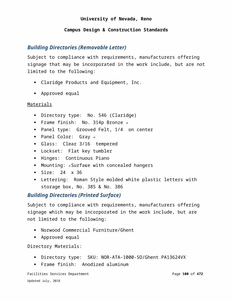
University of Nevada, Reno
Campus Design & Construction Standards
Bicycle RacksVictor Stanley or equivalent
Recycling Containers3540 Slim Jim Waste/Recycle Container by Rubbermaid
Rubbermaid Commercial 1788372 Single Stream Recycling Top, For Slim Jim Container
Outdoor Seating and TablesWabash Valley – Plasticol-coated furniture
Victor Stanley – Steel Site Series (see diagram 1.0)
Diagram 1.0
Facilities Services Department Page 100 of 349
Updated July, 2018

University of Nevada, Reno
Campus Design & Construction Standards
Facilities Services Department Page 101 of 349
Updated July, 2018

University of Nevada, Reno
Campus Design & Construction Standards
End of Division 12
FURNISHINGS
DIVISION 14: CONVEYING EQUIPMENT
142000 - ELEVATORS
SYSTEM DESIGN AND PERFORMANCE REQUIREMENTSComply with regulations for elevators, dumbwaiters, escalators, moving walks, and related equipment per NAC 618.400 – 618.507.
All hydraulic elevators shall have a sprinkler head in the pit and must have a Zoeller Model # N292 sump pump with double piggyback variable level float switches and alarm system A-pak II float switch, horn and light warning in a 2 foot by 2 foot by 2 foot deep recessed pit and a shunt trip connected to the fire alarm.
Elevator controls shall be manufactured by “Motion Control Engineering” (MCE). No substitutes. Machine-room-less systems are not acceptable.
Elevators serving buildings three stories or less shall be double lined hole-less hydraulic elevators with minimum speed of 125 feet per minute.
Elevators serving buildings four stories or less shall be in double lined ground or telescopic jackshaft hydraulic elevators with minimum speed of 125 feet per minute.
Elevators serving buildings more than four stories shall be geared traction elevators using steel cables with minimum speed of 350 feet per minute.
Emergency and Fire Recall Devices shall comply with University Standards and State Elevator Inspection requirements. Facilities Service Department to review and approve.
PRODUCT STANDARDS AND MANUFACTURERSController Motion Control Engineering, no substitute
Door Hanger GAL Manufacturing, or approved equal
Facilities Services Department Page 102 of 349
Updated July, 2018
University of Nevada, Reno
Campus Design & Construction Standards
Door Operators GAL Manufacturing, or approved equal
Door ClutchesGAL Manufacturing, or approved equal
Geared Traction Drive MachineHollister-Whitney, or approved equal with steel cables
Elevator Safety Door EdgesJanus Pana 40, no substitute
Elevator Ceiling Cab Lights LED down lighting, no substitute
Car StationGAL Manufacturing Traditional Design, VPMC Series, or approved equal
Digital Hall Position IndicatorGAL Manufacturing Traditional Design, VPMC Series, or approved equal
Digital Hall Lantern GAL Manufacturing Traditional Design, VPMC Series, or approved equal
Hall StationGAL Manufacturing Traditional Design, VPMC Series, or approved equal
142713 - CAB FINISHES
SYSTEM DESIGN AND PERFORMANCE REQUIREMENTSMaterials in their end-use configuration shall conform to the following requirements, based on the tests conducted in accordance with the requirement of ANSI/UL 723 (ASTM E84), NFPA 252, or CAN/ULC-S102.2, whichever is applicable:
Flame Spread rating of 0 to 75 Smoke development of 0 to 450
Facilities Services Department Page 103 of 349
Updated July, 2018

University of Nevada, Reno
Campus Design & Construction Standards
Floor coverings, underlayment and adhesives shall have a critical radiant flux of not less than 0.45 W/cm2, as measured by ASTM 648 or conform to the requirement of NBCC and ULC standard CAN/ULC-S 102.2, whichever is applicable.
PRODUCT STANDARDS AND MANUFACTURERSRecommended flooring is Mannington Assurance II, Slip Retardant Sheet Flooring
End of Division 14CONVEYING EQUIPMENT
Facilities Services Department Page 104 of 349
Updated July, 2018
University of Nevada, Reno
Campus Design & Construction Standards
DIVISION 21: FIRE SUPPRESSION
211100 - FIRE PROTECTION PIPING
SYSTEM DESIGN AND PERFORMANCE STANDARDSAll fire protection systems shall be designed in accordance with NFPA 13. All building fire suppression piping systems shall be made with A53 Grade B carbon steel pipe. Threaded pipe fittings with schedule 40 steel pipe or Victaulic fittings with ASTM A135 schedule 10 steel pipe.
All devices shall be UL listed.
All fire sprinkler riser main drains shall be piped external to the building or tied into a fire sprinkler drain loop. Use of floor drains/slop sinks is prohibited.
All auxiliary drains must be piped to any of the following:
Exterior of building, Fire sprinkler drain loop, Floor drain, or Custodial slop sink.
Auxiliary drain valve not to exceed 8’ AFF and be readily accessible to a hose for draining. All auxiliary drain locations must be approved by UNR Fire/Life Safety shop prior to installation.
211300 - FIRE SPRINKLER SYSTEMS
SYSTEM DESIGN AND PERFORMANCE STANDARDSAll University of Nevada Fire sprinkler systems shall be connected to a monitored University of Nevada fire alarm system.
Each wet, dry, and specialty type system shall be design-build per project design by a licensed State of Nevada Contractor.
Strict adherence to NFPA guidelines as applied by State of Nevada NAC/NRS must be followed.
Facilities Services Department Page 105 of 349
Updated July, 2018
University of Nevada, Reno
Campus Design & Construction Standards
The fire sprinkler water service to each building shall incorporate a double check detector assembly or a reduced pressure backflow preventer to protect the water supply from backflow. The selected device shall be located as directed by TMWA and Facilities Services.
All fire sprinkler control valves, sectional valves, and inspection test valves to be mounted at a height no greater than 6’ AFF wherever possible.
All anti-freeze refill and inspection points to be mounted at a height no greater than 6’ AFF wherever possible.
All new dry system installations shall include their own dedicated air compressor and an external resetting type dry pipe valve device. Dry system components to be mounted at a height no greater than 6’ AFF wherever possible.
211313 - FIRE SUPPRESSION
SYSTEM DESIGN AND PERFORMANCE STANDARDSFire ExtinguishersExtinguishers and cabinets shall be clearly labeled as to their location on plans.
All fire extinguisher cabinets shall be latch closure, non-locking type.
All CO2 type extinguishers shall be no larger than 10lb. unless specifically specified and approved by UNR Facilities department.
PRODUCT STANDARDS AND MANUFACTURERSAll University of Nevada fire extinguishers shall be Amerex brand.
End of Division 21
FIRE SUPPRESSION
Facilities Services Department Page 106 of 349
Updated July, 2018

University of Nevada, Reno
Campus Design & Construction Standards
DIVISION 22: PLUMBING220000 - GENERAL REQUIREMENTS
SYSTEM DESIGN AND PERFORMANCE REQUIREMENTS
ROOF DRAINSDo not attach roof drains to structural members. Roof drains shall be piped to storm sewer if available. Do not pipe roof drains to any sidewalk or pedestrian paths. Provide splash blocks in landscape areas. No scuppers or external gutter and downspout systems allowed. Roof drains and covers shall be cast iron. Plastic drains are prohibited.
Minimum size for all roof and over-flow drains shall be 3”. All outflows through the building walls above grade shall be via a J.R. Smith 1770 downspout, or equal.
All waste lines into indirect wastes shall have an air gap of a minimum of 1 inch above the overflow rim. All solder or low fusion joints must be lead free.
FLOOR DRAINSEvery toilet room and custodial room shall have a floor drain located at the lowest point in the floor. Provide trap primers on all floor drains, or floor sinks.
Air handler and mechanical equipment rooms shall have oversize drain located at the lowest point of the floor. Locate floor sinks adjacent to equipment that requires condensate drainage. All mechanical room floor drains and floor sinks shall be 4” diameter.
Wherever a plumbing pipe penetrates a concrete floor slab the pipe shall be protected with a minimum of 1/2” thick insulation (typically closed cell elastomeric type insulation). Where site conditions warrant, pipe sleeves and water-tight seals shall be specified at each penetration.
Water hammer arrestors shall be provided as required to protect against noise and damage from water hammer (sizes and locations shall be in accordance with UPC, chapter 6).
ISOLATION VALVES
Facilities Services Department Page 107 of 349
Updated July, 2018
University of Nevada, Reno
Campus Design & Construction Standards
Isolation valves shall be installed on the hot and cold water supply for each floor of the building. Isolation valves shall be installed on the main water lines to each building.
Isolation valves shall be installed on the branches to each group of restrooms.
A shut-off valve and pressure reducing valve, where required, with full size bypass shall be installed on the domestic cold water riser in each building.
The isolation valves shall be located for easy access in an emergency. Isolation valves shall be wall mounted no lower than 3 feet and no higher than 5 feet.
PIPINGAll copper pipe, both domestic and waste, installed on a metal framing system such as Unistrut, shall be isolated using Cush-A-Clamps or equivalent.
Plastic pipe shall be limited inside of buildings as follows:
For reverse osmosis/de-ionized laboratory water systems virgin, unpigmented polyvinylidene fluoride pipe (PVDF) ASTM 3222, schedule 80 shall be specified. Fittings shall be unpigmented polyvinylidene fluoride pipe (PVDF)m schedule 80, socket fusion type joints.
For laboratory waste piping acid resistant, schedule 40 flame retardant polypropylene pipe per ASTM F1412 and ASTM D4101 shall be used except in return air plenums, which requires schedule 40 polyvinylidene fluoride pipe (PVDF) per ASTM F1673 and ATM D3222. Fittings to be schedule 40, no-hub or electrofusion depending on access to the piping. Electrofusion joints required were access to fittings is not practical. All polyvinylidene fluoride pipe (PVDF) to meet ASTM E-74 and UL 723 requirements for flame spread and smoke generation.
5 inch diameter piping shall not be specified.
A lockable cover, loose keyed hose bib shall be provided in each toilet room. The hose bib shall be attached to the hot water supply.
Automatic flushometers shall be battery powered, infrared type with a manual override button.
Winterization: The following methods of winterization are required to ensure adequate protection of lines during colder weather months.
Facilities Services Department Page 108 of 349
Updated July, 2018
University of Nevada, Reno
Campus Design & Construction Standards
INSULATIONHeating: Winterizing with heating should not be used where other methods can be used.
Any of the following heating systems may be used:
Internal heat tracing External heat tracing Jacketing Electrical tracing Routing along and/or insulating together with a hot line.
Vent / Drain on lines and equipment
221119 - DOMESTIC WATER PIPING SPECIALTIES (BACKFLOW PREVENTION)
SYSTEM DESIGN AND PERFORMANCE REQUIREMENTSDomestic cold water service to each building shall incorporate a reduced pressure backflow preventer to protect the water supply from backflow. The reduced pressure backflow preventer shall be located as directed by Facilities Services Department requirements.
Backflow preventers shall be mounted above ground in a weather sheltered area with at least three feet of clear space on either side of the preventer. The backflow preventer shall be located so no part of the building needs to be dismantled to replace the preventer. All exterior locations or other sites subject to freezing shall be provided with insulated, lockable hot boxes.
Provide two types of heat sources.
Electric heater supplied with large hot box and heat tape, small hot boxes not supplied with heater, require only two heat tapes each on separate circuits.
Two heat tapes: Heat tapes to be manufactured by Raychem and be self-regulating, braided copper; commercial style or equal.
Each heat tape installed individually must cover the main backflow, bypass and piping.
Facilities Services Department Page 109 of 349
Updated July, 2018
University of Nevada, Reno
Campus Design & Construction Standards
All bypass water lines shall have the same type of backflow prevention as the backflow prevention on the main water service.
Installation of an appropriately sized thermal expansion tank is required on hot water lines downstream of the backflow prevention device.
Any outlets, tees, tap, hose bib connections, must be down-stream of the backflow prevention assembly.
The backflow prevention assembly shall be sized the same as the inlet pipe size diameter.
All piping up to and including 4” in diameter shall be type L copper pipe, underground piping shall be wrapped with 10-mil tape. Copper pipe shall extend 6’ beyond both sides of the backflow for support.
Service protection backflow prevention assemblies shall not be installed in attics, above ceilings, or behind walls. Assemblies more than 5 feet above the grade of the floor shall have a permanent platform.
A drain system shall be required for all Reduced Pressure RP assemblies.
All boiler and cooling tower feeds must be equipped with approved back flow preventer and full sized by-pass.
Fire Protection Backflow PreventionThe fire sprinkler water service to each building shall incorporate a double check detector assembly or a reduced pressure backflow preventer to protect the water supply from backflow.
See Drawings for Backflow Prevention Assemblies Detail Backflow External Horizontal – Industrial-Domestic (221113-1)
Backflow Internal Horizontal Retrofit Only (221113-2)
Backflow Irrigation Horizontal (221113-3)
Backflow External Horizontal Above Ground (221113-4)
Backflow Internal Installation (221113-6)
Backflow Assemblies Internal Vertical (221113-8)
Backflow External Horizontal (221113-9)
Facilities Services Department Page 110 of 349
Updated July, 2018

University of Nevada, Reno
Campus Design & Construction Standards
Backflow Internal Horizontal – Fire System (221113-10)
PRODUCT STANDARDS AND MANUFACTURERSBackflow Preventers: Apollo Backflow Preventers required.
Backflow preventers shall be listed on the most recent “List of Approved Backflow Prevention Assemblies” published by the Foundation for Cross-Connection Control and Hydraulic Research of the University of Southern California. A manufacturer’s label verifying approval by the Foundation for Cross-Connection Control and Hydraulic Research of the University of Southern California shall be provided with each backflow preventer.
Installation of backflow preventers in vaults is prohibited without permission from Facilities Services.
224200 - PLUMBING FIXTURES AND TRIM
SYSTEM DESIGN AND PERFORMANCE REQUIREMENTSThe minimum number of plumbing fixtures shall be in accordance with the locally adopted International Building Code (IBC).
All plumbing fixtures shall be specifically designed to conserve water. Maximum water usage by specific fixture type shall be as follows:
Water Closets 1.28 gallons per flush
Urinals 0.5 gallons per flush
Lavatories 0.5 gallons per minute
Sinks 1.5 gallons per minute
Showers 1.5 gallons per minute
Exterior hose bibs shall be installed every 50 feet on all sides of buildings.
Water closets shall be wall-mounted type (except in remodel construction where existing wall or chase space does not allow for wall-mounted type) unless written authorization is obtained from the University Facilities Services Department allowing floor-mounted water closets.
Sinks shall be under mounted where applicable.
Facilities Services Department Page 111 of 349
Updated July, 2018

University of Nevada, Reno
Campus Design & Construction Standards
All industrial and potable water fixtures/systems must have backflow preventers that meet TMWA standards and Washoe County Health Codes and be on a backflow preventer list. (A copy can be obtained from TMWA backflow department.)
All faucets with any possibility of back-siphon into potable water must be equipped with vacuum breakers. Provide faucets with grid strainers only, pop-up are not allowed.
All new construction shall include automatic flush devices and faucets.
PRODUCT STANDARDS AND MANUFACTURERSFaucetsAutomatic faucets for lavatories:
120 or 240 volt models
Moen 8553AC sensor operated faucet with 99557 4” deck plate with 104424 mixing valve
Sloan Optima Systems ETF-600
No Symmons faucets or valves will be accepted.
Battery Powered Models: Moen 8553 sensor operated faucet with 99557 4” deck plate with 104424 mixing
valve.
Sloan Optima Systems EBF-650
Manual Devices are to be used only with written approval from Facilities Services.
Faucet: 4” center Moen 8437 or 8430F05. Lever handle: Moen 8420.
Kitchen Faucet: 8” center Moen 8701, 8707.
Handicapped wrist blade faucet: 4” center Moen 8215F05 or Moen gooseneck 8278.
Scullery faucet: Moen 8119 with 12” spout or Chicago 445
Facilities Services Department Page 112 of 349
Updated July, 2018

University of Nevada, Reno
Campus Design & Construction Standards
Shower Valves3 port: Moen 8371HD (valve only), Moen T8375EP15 (shower head & trim only)
4 port: Moen 8371HD (valve only), Moen T8389EP15 (shower head, tub filler & trim only)
UrinalsAutomatic flush valves for urinals:
120 volt models
Moen 8315AC05 sensor-operated flush valve – 0.5 GPF with 104406 AC adapter
104401 multi AC adapter for up to 8 valves, 104402 needed for every valve
Sloan Royal Optima 186-.05 ES-S OPT with Sloan EL 154
Battery powered models:
Moen 8315 sensor operated flush valve – 0.5 GPF
Sloan Royal Optima Plus 8186-.05 MC
Automatic flush valves for water closets:
120 or 240 volt Models
Moen 8311AC12 sensor operated flush valve – 1.28 GPF with 104406 AC adapter
104401 multi AC adapter for up to 8 valves, 104402 needed for every valve
Sloan Royal 110 ES-S
Sloan Royal 111 ES-S
Battery powered models:
Moen 8311 sensor operated flush valve – 1.28 GPF
Sloan Royal Optima Plus 8110
Sloan Royal Optima Plus 8111
Facilities Services Department Page 113 of 349
Updated July, 2018
University of Nevada, Reno
Campus Design & Construction Standards
Flush ValvesWater Closet Flush Valves: Moen 8310M128 – 1.28 GPF or Sloan Royal 110-3 with 1” VR control stop, 1-1/2” tailpiece, heavy duty brass piston and brass handle assembly
Urinal Flush Valve: Moen 8312M05 – 0.5 GPF or Sloan Royal Optima 186-0.5 with 3/4” VR control stop, ¾” tailpiece, heavy duty brass piston and brass handle assembly
Sinks, Water Closets, and Urinals: American Standard and Kohler
Hose Bibbs: Zurn or Woodford
Medical Surgeons Lav: American Standard 9010.018 or 9012.14 with concealed arms and Moen 8225 gooseneck faucet.
Service Sink: Moen 8124 with internal check stop and with vacuum breaker
Stainless Sinks: Minimum of #18 1.2mm gauge type 304- 18-8 stainless sinks.
Water Cooler: Elkay LZSTLG8WSSK Bi-level ADA with bottle filler. Elkay LZS8WSLK single ADA unit with bottle filler where appropriate.
Hydration Station: Elkay or Brita/Haws Touch Free Hydration Station. Note: this does not alleviate the requirement for water fountains.
Floor Drain Trap Primers: Within restrooms use Sloan Vacuum Breaker Trap Primer, Model # VBF-72-A. Where water is not close to floor drain, use Sure Seal Trap Guard. All other applications require a Prime-Time electronic trap priming system PPP model PTS-4 manifold system.
Water Closet
Wall mounted toilets will be American Standard or Kohler.
Floor mount toilets will be American Standard
Water Closet Carrier
Carriers will be Zurn floor mounted closet carriers, vertical and horizontal.
All anchor lugs shall be secured using ½” all-thread rod with ½” drop in anchor in concrete application.
Facilities Services Department Page 114 of 349
Updated July, 2018
University of Nevada, Reno
Campus Design & Construction Standards
Wood application will require all-thread to penetrate the floor below and be secured with uni-strut to a solid wood structure.
Floor Mount Toilets
10 inch or 12 inch rough in and ADA compliant
Material installation requirements
Offset closet flanges are not allowed.
223330 - DOMESTIC HOT WATER HEATERS
SYSTEM DESIGN AND PERFORMANCE REQUIREMENTSBuildings attached to the Central Heat Plant will utilize a shell and tube heat exchanger to provide domestic heat. The heat exchanger will utilize 180 degrees F water from the building.
Storage tanks to be cement-lined steel with stainless steel threaded connections.
Tank to be insulated with minimum 2 inch fiberglass insulation and 18 gauge epoxy painted steel jacket.
Buildings not tied to the Central Heat Plant will utilize a gas fired water heater.
PRODUCT STANDARDS AND MANUFACTURERSWater Heaters: State or A.O. Smith
226700 - LABORATORY AND DEIONIZED WATER SYSTEMS
See APPENDIX H- Laboratory Safety Design Guidelines
SYSTEM DESIGN AND PERFORMANCE REQUIREMENTS
Facilities Services Department Page 115 of 349
Updated July, 2018

University of Nevada, Reno
Campus Design & Construction Standards
Specify the type of water to be distributed. Type 1, 2 or 3 are the categories lab water is typically specified. Type 3 is for general and non-critical applications. Type 2 for activities such as buffer preparation, pH solution preparation, re-agents preparation. Type1 water is for critical applications - cell cultures, molecular biology, etc. ASTM D1193-1999 specifies quality of different water types.
During programming, the Architect shall interview faculty to determine requirements for deionized water systems. Consider point of use systems for Type 1 water. Central system can be Type 2 if feeding a Type 1 point of use system.
Consider floor by floor systems to minimize risk of contamination and downtime.
City water quality may vary day to day and by season. Must evaluate water quality in selecting pre-filtering components.
Use an activated carbon filter upstream of Reverse –Osmosis (RO) system to remove chlorine. Chlorine can damage RO membranes.
Cation and anion exchange shall not be used.
Specify systems with EDI - Electrodeionization, which uses electrical current and permeable membranes for ion removal.
Use R.O. feed water to an EDI system.
Specify UV lamps 185 nm and 254 nm wavelengths, which are the most effective.
Use chlorine dioxide to sanitize DI piping systems.
Polyvinylidene Fluoride PVDF piping is preferred. PVDF manufactured per ASTM E-84 and UL 723. The only alternative is stainless steel. (Type 316 L). Do not use PVC piping. Do not use solvent welded joints, glue will contaminate system.
Use diaphragm valves only.
Design with zero dead-legs in piping system. (No greater than 6 pipe diameters)
Sanitary sampling valve - use needle valve for microbiological sampling.
Do not oversize. Size storage tanks for one day’s supply.
Gravity systems are not acceptable.
Facilities Services Department Page 116 of 349
Updated July, 2018

University of Nevada, Reno
Campus Design & Construction Standards
Distilled water systems are not acceptable.
Resistivity and TOC monitoring are needed.
For critical systems specify duplex systems for reliability.
End of Division 22PLUMBING
Facilities Services Department Page 117 of 349
Updated July, 2018
University of Nevada, Reno
Campus Design & Construction Standards
DIVISION 23: HEATING, VENTILATING AND AIR CONDITIONING
23000 - BASIC REQUIREMENTS
SYSTEM DESIGN AND PERFORMANCE REQUIREMENTSEnergy Conservation: Prior to the construction or renovation of any public building with a gross floor area greater than 20,000 square feet, a detailed life cycle cost analysis, including the cost of operation and maintenance, must be completed. The study shall identify measures for the conservation of energy, and shall consider the use of alternate non-fossil fuels when applicable. The analysis shall include comparisons of at least three different HVAC system types. The three different system types to be evaluated shall be reviewed and approved by the University Facilities Services Mechanical Engineer prior to beginning the analysis. A separate narrative shall be provided outlining the building envelope insulating values (for walls, glass, roof, etc.) and specific HVAC system components (i.e., plate and frame heat exchangers, variable frequency drives, compensating type kitchen exhaust hoods, etc.) as they relate to energy conservation.
HVAC SYSTEMS AND EQUIPMENTAll new buildings shall utilize heat provided by the Utility Plant unless directed otherwise by the Facilities Services Department (FSD).
All new buildings shall utilize cooling provided by the Utility Plant unless directed otherwise by the Facilities Services Department (FSD).
Heating and air conditioning load calculations for Reno Nevada shall be completed utilizing the following criteria:
Indoor/Outdoor
Heating 72F ASHRAE 99% Winter Value = 13F db
Cooling 74F 95 F db / 61F wb
All equipment shall be rated for an elevation of 5,000 feet above mean sea level. Propylene glycol shall be used in any system that has a hydronic coil and uses 100% outside air such as a makeup air unit. This pertains to new systems as well as existing. Engineering calculations shall be performed on the entire new or existing hydronic
Facilities Services Department Page 118 of 349
Updated July, 2018
University of Nevada, Reno
Campus Design & Construction Standards
system to verify that the equipment will perform satisfactorily with glycol. Glycol shall be added to the system in the amount to provide freeze protection down to 0ºF, unless specifically requested otherwise by Facilities Services. The percentage of glycol added to the system shall not exceed 40%.
Heating and air conditioning load calculations shall not incorporate safety factors. Safety factors shall only be applied in selecting the desired equipment.
All equipment, ductwork, and piping shall be braced for the applicable seismic zone. Seismic bracing requirements shall be specifically identified in the Contract Documents.
All equipment and equipment rooms shall be designed to ensure adequate provisions for maintenance. Special consideration shall be given to ensure proper clearances for maintenance of filters and removal of chiller and boiler tubes, fan housings, and fan shafts.
Access to equipment for service and maintenance shall be coordinated with FSD. Required clearances shall be specifically identified on the drawings (for equipment such as fan coils, VAV boxes, air handling units, control panels, etc.). Coordinate with other disciplines to ensure that other trades (electrical, fire sprinkler, etc.) are made aware of the required clearances.
Pumps shall be laser aligned after installation with any misalignment correct to eliminate rotation rate vibration.
Mechanical equipment rooms that utilize water in any way and are located above any other space shall have the floor sealed in such a way as to not allow water to seep through the floor to the space below. Critical areas shall be provided with water detectors with alarming through the BMS. Floor drains shall be provided complete with automatic trap primers. These rooms shall also be provided with at least one anti-siphon hose bib.
Designs shall include isolation and drain valves, with a hose bib connection, at each floor or major building section.
PRODUCT STANDARDS AND MANUFACTURERSThe following manufacturers shall be used for the equipment listed:
Frequency Drives: ABB Danfoss Roof-top units: York, Carrier, Trane
Facilities Services Department Page 119 of 349
Updated July, 2018
University of Nevada, Reno
Campus Design & Construction Standards
Dual Fuel, Steel, Hot Water Boilers: Fulton (Vertical/tubeless), Cleaver Brooks, Bryan, Parker, Burnham, International Boiler Works
Modular, Copper Fin, Gas-Fired Hot Water Boilers: Lochinvar, Hydrotherm Chillers: Carrier, Trane, York, Daikin Centrifugal Pumps: Goulds or Bell & Gossett Custom Air Handlers: Temptrol, Scott Springfield, Governair, Marcraft, Energy Labs Plate and Frame Heat Exchangers: Alfa-Laval Tranter, Sondex, Bell & Gossett Shell and Tube Heat Exchangers: Bell & Gossett Make-Up Air Units: Greenheck, Reznor, Modine, Trane, Rapid, Aaon Air Separators: Spirotherm, Thrush Aar-O-Vent Pneumatic Control Valves: Leslie Buried High Temperature Hot Water (HTHW) Piping Powder Insulation: Gilsulate
500XR.
INSTRUMENTATION AND CONTROL FOR HVACBuilding Management Systems (BMS) DDC Control ModulesAll control components in new buildings shall be native Automated Logic Controls (ALC). No exceptions.
All new buildings shall use BACnet standard MS/TP, TCP/IP bus protocol ASHRAE Standard-135 or ALC Arcnet. Additions to existing buildings may be BACnet, MSTP, or ALC Arcnet. Alternatives will be considered on a case by case scenario with the UNR Controls Department. , ALC BACnet Routers shall be used. BACnet IP shall be used for the Global level communications. All new construction must provide graphics with accompanying text fields for all pertinent data along with user view trees (contact University Controls Department for any questions). Servers are used as part of the BMS for extensive archiving of system configuration data, trending, operator transactions, and alarming purposes. These functions shall be performed through the use of virtual servers for the ALC systems. All shall use SQL databases.
The control system shall provide direct digital control with a Windows-based user interface. The DDC shall include surge suppressors, operating software. All software shall be updated to the latest revision. Check with the University Controls Department before performing any upgrades.
Facilities Services Department Page 120 of 349
Updated July, 2018
University of Nevada, Reno
Campus Design & Construction Standards
All control components in buildings connected to the South Campus Chilled Water System that will be added to the existing chilled water control system shall be native ALC to match the existing control architecture. No exceptions. The existing chilled water loop controller programming shall be modified to include all points necessary to match the existing sequence of operation and all associated graphic displays shall be updated.
BMS Software and Programming RequirementsThe Temperature Control Contractor shall program the eleven State Holidays into the EMCS software for the five years following the date of the installation.
A separate occupied/unoccupied schedule shall be provided for each air handling unit, fan coil unit, exhaust fan, and/or other individual air handling system.
Outside air temperature sensors capable of sensing both temperature and humidity shall be programmed to display dry bulb temperature, wet bulb temperature, and relative humidity. The campus is divided into climatic zones. The Temperature Controls Contractor shall map the point from the applicable climatic zone in addition to installing a new sensor. The system shall be programmed to use the global sensor as primary outside air conditions and, upon failure of the primary, switch to the buildings local sensors. Each building shall utilize its own outside air conditions program that all building systems point to.
Each zone shall be capable of being set to either a global set point or a remote set point with adjustable dead bands for each. The global set point can be utilized to set/adjust the temperature in all associated zones with a single set point. Each air handling unit and its associated zones and/or each floor of fan coil units shall have a separate global set point. The strategy for global set point assignment shall be confirmed with the University Controls Department prior to programming. The remote set point is an individually adjustable set point for each zone provided by the Controls Department. All zones shall also be capable of being put into local control with the occupant having the ability to change the zone set point +/- 2°F (adjustable).
30-minute point history samples will be provided on all analog points and all inputs and outputs involved in control loops for 72 hours of first in first out data trends. Binary inputs and outputs to trend change of state.
Every piece of powered equipment shall incorporate in its programming a means to manually start or stop the equipment. This is typically accomplished by the use of an on-
Facilities Services Department Page 121 of 349
Updated July, 2018
University of Nevada, Reno
Campus Design & Construction Standards
off-auto switch. This switch shall be brought forward to the graphic and incorporated into the building shutdown logic as noted in VII.
Buildings shall have programming added to facilitate scheduled and immediate building wide systems shutdowns. This programming shall have the ability to be scheduled via a wire lock in ALC. This is mainly used for planned power outages to shut down every piece of equipment in the building. This programming shall only be accessible by operators that have “admin” rights to the system. No other operators shall be allowed access to building shutdown programming.
Fault Detection and Diagnostics (FDD) Internal Fault Detection and Diagnostics shall be provided, installed and fully configured. FDD shall have the ability to follow NIST and ASHRAE standards for enhanced monitoring and alarming. The capability of FDD shall reside in the controller and integral to the programming. External software for primary FDD reporting is not acceptable. FDD capabilities shall include diagnostics for: Simultaneous Heating and Cooling; Continuous Operation; Fraction of Outdoor Air; Analog Output Cycling; Discrete Output Cycling; Sensor Failures; and Run Requests Analytics. Equipment using these FDD capabilities, as a minimum, shall include: Single Zone Units (SZU), VAV Air Handlers, VAV Terminal Units, Fan Coils, Unit Ventilators, Air Source & Water Source Heat Pumps. FDD software shall be configured to prevent cascading alarms.
Environmental Index System Environmental index systems shall monitor all occupied zones and compile an index that provides a numerical indication of the environmental comfort within the zone. As a minimum, this indication shall be based upon the deviation of the zone temperature from the heating or cooling set point. If humidity is being measured within the zone then the environmental index shall be adjusted to reflect a lower comfort level for high or low humidity levels. Similarly, if carbon dioxide levels are being measured as an indication of ventilation effectiveness then the environmental index shall be adjusted to indicate degraded comfort at high carbon dioxide levels. Other adjustments may be made to the environmental index based upon additional measurements. The system shall maintain a trend of the environmental index for each zone in the trend log. The system shall also compute an average comfort index for every building included in this contract and maintain trend logs of these building environmental indices. Similarly, the system shall compute the percentage of occupied time that comfortable conditions were maintained within the zones. Through the UI the user shall be able to add a weighting factor to
Facilities Services Department Page 122 of 349
Updated July, 2018

University of Nevada, Reno
Campus Design & Construction Standards
adjust the contribution of each zone to the average index based upon the floor area of the zone, importance of the zone, or other static criteria.
Sustainability Kiosk Contractor Sustainability kiosk contractor shall provide all software, programming, content, computer or web server hardware, touchscreen panels, and configuration to display building sustainability. The purpose of this display is to inform and educate visitors and building occupants on the various systems and sustainability features of the building or buildings included in this project. The display shall allow a user to navigate through the screens by touching icons or other controls. Screens shall also be viewable through a standard web browser with a network connection to the contractor supplied hardware. Display shall highlight the sustainability features of the project by displaying automatically updated graphs that show energy use, water consumption, natural gas consumption, and sustainable features incorporated into the building such as solar panels, solar water heating, rainwater collection, geothermal heating and cooling, and similar features as applicable to the project. Display shall provide educational material about the resource being trended as well as tips on how building occupants can help reduce the use of these resources. Display shall also provide animated graphics and simple explanations about how basic building systems included in this project operate and how they affect energy consumption. Systems covered shall as a minimum include air handling units, boilers, chilled beam systems, energy recovery wheels, geothermal heat pump systems, rainwater recovery systems, solar water heating systems, solar photovoltaic panels, and wind turbine generators if such equipment is included in the project.
GRAPHIC DISPLAYS Campus GraphicThe campus graphic shall show all University buildings. The main campus graphic shall be updated to include any new buildings added to campus.
Each building footprint shall be a link to that building’s main screen.
If an alarm is present anywhere in a building, the footprint shall be red. If the building global controller is offline, the footprint shall turn pink.
Facilities Services Department Page 123 of 349
Updated July, 2018
University of Nevada, Reno
Campus Design & Construction Standards
System Wide GraphicsUNR uses some system wide graphics such as but not limited to south campus chilled water, peer caching, global building shutdown screen, HTHW heat exchanger summaries, boiler summaries, snow melt system summaries, air compressor summaries, and domestic water summaries.
Anytime work is done on campus to any system, the associated system wide graphic shall be updated with the new information.
Common Main Screen/Sub-screen ItemsBegin all graphics with the default screen layout for “graphic without navigation tree” (980W x 652H).
The first letter of each word and all acronyms shall be capitalized.
All text shall be standardized as Arial 12pt. except for:
Equipment labels: Arial/12pt/bold adjacent to equipment (above if possible) Links: Arial Unicode MS/12pt/bold/underlined/left justified, located at top left of
page. Links should reflect screen names, but may be abbreviated. Building names: Arial/14pt/bold/center justified, located at top center. Date & Time: Arial Unicode MS/12pt/yellow, locate the date and time on the top
center below the screen name. The date (format: month/day/year) followed by day of week. The time follows date (format: hour/minute/am, pm) all on a single line.
If a screen is a thermographic floor plan, it shall follow the guidelines under “Main Screen”.
Variable formatting: All temperatures, pressures, flows, energy readings and analog outputs shall exclude decimal places with the following exceptions:
Zone, OSA DB, OSA WB temperatures, and water loop differential pressures shall have a single decimal place.
Duct and filter pressures shall have two decimal places. Building static pressure shall have three decimal places.
Facilities Services Department Page 124 of 349
Updated July, 2018

University of Nevada, Reno
Campus Design & Construction Standards
Main ScreenBuilding picture (small) to be located at top right quadrant with OSA-DB, %RH and Sun/cloud symbol. This is the only page where %RH shall be shown except for humidifiers, and zone humidification sensors.
Graphic screen links:Equipment may be accessed through the actual equipment footprints as shown on the floor plans. Equipment text names shall be displayed on each floor graphic sub screen.
In addition to equipment footprint links, there shall be other links in text, examples are shown below (If an alarm is present in a specific piece of equipment, the link text shall be colored red.):
UNR Campus Energy Heating Hot Water Chilled Water AHU: 1-X Fan Coils Lighting Documents Miscellaneous
For small projects, the thermographic floor plans and text links may all be on the main screen. For larger projects, there shall be a link to a Text Link Page following the Main Screen. The Text Link Page shall provide enough space for all the building equipment allowing the equipment to be reached either through the Text Link Page, or the floor plans.
Organize the tree to match the equipment link order.
“Summer/Winter” mode, shall be located on the main screen under time/date.
Thermographic floor plansThe color code legend shall be below the floor plans with the North indicator to the right of the legend. The color code shall be as follows:
Green = satisfied within dead band, typically 69-77°F Yellow is up to two degrees hotter than Green’s range (77-79°F)
Facilities Services Department Page 125 of 349
Updated July, 2018
University of Nevada, Reno
Campus Design & Construction Standards
Orange is up to two degrees hotter than Yellow’s range (79-81°F) Red is hotter than Orange’s range (>81°F) Light blue is up to two degrees cooler than Green’s range (69-67°F) Dark Blue is up to two degrees cooler than Light Blue’s range (67-65°F) Red is cooler than Dark Blue’s range (<65°F)
Thermographic screens shall be interactive on the main screen. The floor text name will link you to a full screen interactive thermographic floor plan.
The entire zone shall be the link, not just a thermostat, or label within the zone. If there is more than one room in a zone, all rooms shall be linked.
Floor plans shall be stripped down from AutoCAD floor plans, and shall include the following.
Room Numbers Thermostat locations Duct and room pressure sensor locations
Equipment locations and designations only if actually located in the space. All rooftop equipment to be shown on a floor plan.
Roll over to show zone equipment name
Sub ScreensScreen name shall follow building name.
Example: Building Name: Screen Name
Screen names shall reflect depicted equipment such as: Hot Water System, Chilled Water System, AHU-1, AHU-1’s VAV’s (if all are shown), AHU-1’s VAV’s: 1-14 (if multiple screens are required), etc.
A miscellaneous graphic shall be used for components not closely associated with other screens such as sump pumps, DW systems, EF’s, etc.
An Energy screen shall display all kW and BTU meter data for each project.
If system has a hand/off/auto switch, it shall be located below the Date/Time text.
Outside air dry bulb temperature shall be shown at top/right on each screen for all air moving equipment next to the Sun/cloud symbol. This value does not need any
Facilities Services Department Page 126 of 349
Updated July, 2018
University of Nevada, Reno
Campus Design & Construction Standards
designation text. Outside air dry bulb, and wet bulb shall be included on all screens with evaporative cooling (cooling towers, etc.) Wet bulb temperature shall be preceded with “WB”. Note: percent relative humidity only to be shown on main screen in this format “XX%RH”.
CHWS and HWS temperatures to be shown at the piping for each associated coil.
At a minimum, each sub screen shall have a link to the “Main” screen. In addition to the main screen, sub screens shall have other links as follows:
AHU’s shall have a link to/from the next/previous AHU, the cooling system and the heating system, and to its VAV summary page if applicable.
VAV summary screens (described below) shall link back to its AHU, or to additional VAV summary pages from this AHU if applicable. Individual VAV graphic pages can be accessed either via thermographic floor plans, or the VAV summary page.
Individual VAV graphics shall have links for the heating system, the cooling system, and the associated AHU.
The Chilled Water System shall have a link to the Condenser Water System, and vice versa.
In general, all data fields shall be adjacent to their associated equipment. Any data fields not associated with a graphic item shall be located at the screen bottom in columns/rows.
Commanded equipment shall follow the command or an alarm shall follow. It shall be commanded on or off with “S/S” such as “S/S On”, or “S/S Off”. A “Status” line shall be located below the command. If the status does not equal the command, a “Failure” text shall show up in red below the status line.
Enabled equipment, such as a boiler, has its own onboard controls start/stop. Therefore, the status may not follow the command and shall not be alarmed. These devices have a separate “Alarm” field. The command for enabled equipment shall still be “S/S” such as “S/S Enabled”, or “S/S Disabled”.
Object labels shall be on the left side (right justified) and data on the right (left justified).
Valve and damper positions shall be shown in “%”. Other text indicating “Open” or “Closed” is not needed since it is assumed to be reading the open position. The
Facilities Services Department Page 127 of 349
Updated July, 2018
University of Nevada, Reno
Campus Design & Construction Standards
exception is for 3-way valves. In this case, locate text identifying the main flow path after the “%” such as “Coil”, or “Chiller”.
Piping lines shall never cross unless there is no other option. If they must cross, one pipe is to show a break. Provide flow direction arrows and water flow animation.
All equipment level graphics shall include an editable multi-line text box to allow the operator to add notes to the graphic.
Summary Screens
Multiple equipment, such as Fan Coils, VAV’s, Exhaust Fans, etc., shall be shown in a summary matrix. Each screen shall provide: zone location, temperature, set point (global/remote), discharge air temperature, valve position, fan command, fan status, dead band set point(s), CFM set points, CFM flow rate, etc. as is applicable for the equipment. Summary screen format and required display data shall be approved by the University Controls Department prior to screen development.
Alarms
Alarm conditions shall be shown in red and shall begin on the campus map with the entire building footprint. When navigating through the main screen, the entire equipment footprint and link shall be red, until you arrive at the final sub-screen. Critical alarms shall follow the same alarm strategy with the exception that they shall flash red on/off at 2-times per second.
The University has an alarm matrix that shall be used to define alarm groups and routing.
Every alarm shall have an associated pop-up.
Offline Controller/Points
Offline controllers and points shall follow the same guidelines as “Alarms” with the exception that the color code shall be pink instead of red. In the event that a piece of equipment has both conditions occurring at the same time, the color code on the equipment link shall be red, but the graphic screen shall differentiate which point(s) are in alarm (red), and which point(s) are experiencing a failure condition (pink). If the entire controller is offline, then all associated point fields shall show pink.
Overrides
Facilities Services Department Page 128 of 349
Updated July, 2018
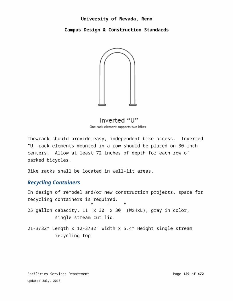
University of Nevada, Reno
Campus Design & Construction Standards
When a point has been manually overridden, both the data and associated text field shall change to orange and shall only show up on the bottom tier graphic.
Custom Graphic ElementsThe University uses some modified graphic elements (.PNG files). All contractors shall use the University data base to keep graphics standard. The contractor shall coordinate with the UNR Controls Shop for custom graphics.
MiscellaneousAll graphic displays shall be submitted to the University Controls Department for review and approval prior to commencing any programming.
All displays specified to be dynamic shall depict motion. Dynamic displays shall include rotating fan wheels and rotating pump impellers and water flow through pipes.
All set points which are identified as “adjustable” in the written control sequences shall be adjustable via the associated graphic displays (including dead band between heating and cooling room set point).
All occupied mode and unoccupied mode room temperature set points shall have an adjustable dead band (adjustable from the associated graphic display).
All inputs and outputs shall be programmed with the capability to override the values via the associated graphic display (this requirement applies to all equipment, valves, dampers, fans, pumps, temperatures, etc.).
The main graphic page shall have a link to the as-built control drawings, all commissioning documentation, schedules and operation and maintenance manuals as well as pictures of the completed panels outside & inside detailed enough to show controllers and wire labeling.
BMS Integration
Direct Protocol (Integrator Panel)
The BMS system shall include appropriate hardware equipment and software to allow bi-directional data communications between the BMS system and 3rd party manufacturers’ control panels. The BMS shall receive, react to, and return information from multiple building systems, including but not limited to chillers, boilers, variable frequency drives, power monitoring system, and medical gas.
Facilities Services Department Page 129 of 349
Updated July, 2018

University of Nevada, Reno
Campus Design & Construction Standards
All data required by the application shall be mapped into the network controller and shall be transparent to the operator.
Input and output points from the third-party controllers shall have real-time interoperability with BMS software features such as: Control Software, Energy Management, Custom Process Programming, Alarm Management, Historical Data and Trend Analysis, Totalization, and Local Area Network Communications.
BACnet Protocol Integration
The neutral protocol used between systems shall be BACnet over Ethernet and comply with the ASHRAE BACnet standard 135.
A complete Protocol Implementation Conformance Statement (PICS) shall be provided for all BACnet system devices.
The ability to command, share point object data, change of state (COS) data and schedules between the host and BACnet systems shall be provided.
When adding a piece of equipment on campus such as an air handler, chiller, package unit, etc. that is BACnet compatible, Bacnet shall be used for monitoring ONLY. No “control” over BACnet is allowed. All start/stop, status, alarm, speed reference, or any other control point shall be hard wired from a BMS controller to the piece of equipment.
Any BACnet device that is connected to the UNR network shall have a unique device ID between 0 and 4194303. The contractor shall contact the UNR Controls Shop for approval of any and all BACnet device ID’s. A seven digit device ID is preferred but not always possible due to BACnet limits. Typically the ID will be vendor ID followed by building number followed by 1-3 identifying numbers. The same holds true for network numbers.
Example:
Danfoss Vendor ID=190 Belimo Vendor ID=423 Lincoln Building #=60 BACnet device for Belimo valves at Lincoln Hall=42360# BACnet device ID for Danfoss VFDs at Lincoln Hall=19060##
Multiple BMS systems integration
Facilities Services Department Page 130 of 349
Updated July, 2018

University of Nevada, Reno
Campus Design & Construction Standards
In buildings where there are more than one BMS manufacturer present, the systems shall be integrated together via BACnet. This includes but not limited to:
Update thermographic floor plans on the ALC system with information from both systems.
Update any affected summary screens on the ALC system with information from both systems.
Program heat and cool requests from one system to the other
Transfer occupancy schedule from ALC system to the other.
Maintain original system functionality by providing any and all programming necessary in both systems i.e., heat/cool requests from TUs or air handling equipment, building static pressure control with common elements, and other building/site wide interdependencies.
Integration of multiple BMS systems within a building shall be completed in such a way as to provide for a complete and operational system completely controlled by the ALC system.
Input DevicesAll equipment shall be sized, selected, installed, setup, and calibrated as appropriate for the application and per the manufacturer’s specifications.
Temperature Sensor General RequirementsTemperature sensors shall be resistance type, and shall be two wire thermistor 10k-2 (10k ohms @ 25C, -55 to 150 C).
Room sensors on exterior walls shall be mounted with adequately insulated bases, and insulation shall be stuffed inside the wall to block off internal wall air flows. Wall boxes shall be caulked around perimeter and conduit penetrations shall be sealed.
All fluid temperature monitoring shall be accomplished by using insertions sensors inside thermo wells. Wells shall be filled with thermal conducting compound.
All HVAC air moving equipment shall have a duct discharge air temperature sensor installed. This includes but is not limited to: Air Handling Units, Roof Top Units, Make Up Air units, Fan Coils, Terminal Units, etc.
Facilities Services Department Page 131 of 349
Updated July, 2018

University of Nevada, Reno
Campus Design & Construction Standards
The following point types (and the accuracy of each) are required, and their associated accuracy values include errors associated with the sensor, lead wire, and A to D conversion:
Chilled Water +/- 0.5°F. Room Temp +/- 0.5°F. Duct Temperature +/- 0.5°F. All others +/- 0.75°F.
Room Temperature SensorsRoom sensors shall be constructed for either surface or wall box mounting.
Room sensors shall have the following options when specified:
Set point adjustment providing a minimum +/- 3 degree (adjustable) range.
A momentary override request push button for activation of after-hour operation with LED status.
Temperature and mode display.
Thermowells When thermo wells are required, the sensor and well shall be supplied as a complete assembly.
Thermo wells shall be pressure rated and constructed in accordance with the system working pressure.
Thermo wells and sensors shall be mounted in a thread-o-let or 1/2” FPT fitting and allow easy access to the sensor for repair or replacement.
Thermo-wells and sensors shall be matched in size. They shall be sized such that the end of the well is located in the center of the pipe.
Thermo-wells shall be constructed of 316 stainless steel, if installed in the High Temperature Hot Water System (HTHWS). All other installations may be brass.
Facilities Services Department Page 132 of 349
Updated July, 2018

University of Nevada, Reno
Campus Design & Construction Standards
Outside Air Sensors The University has divided its campus into zones which group buildings into similar OSA climates. Each zone has a NIST certified Vaisala OSA temperature sensor and %RH transmitter. The values from these devices are mapped across the BMS network to all buildings in their respective zones.
New buildings or new control installations in buildings that do not have a standalone OSA sensor shall have a new OSA and %RH sensor installed. After the new control system is brought online on the campus network, the existing climatic zone sensors shall be programmed as the primary sensor and the building’s standalone sensors shall be programmed as the backup in the event that the primary goes unreliable. In addition, the program shall be written to allow for manually selecting which sensor is used as the primary.
Duct Mount Sensors Duct mount sensors shall mount in an electrical box through a hole in the duct, and be positioned to be easily accessible for repair or replacement.
If the duct has exterior insulation, the sensor shall be provided with standoff spacers with insulating material firmly fitted around spacers.
Duct sensors shall be insertion type and constructed as a complete assembly, including lock nut and mounting plate.
For outdoor duct applications, a weatherproof mounting box with weatherproof cover and gasket shall be used.
Averaging Sensors For ductwork greater in any dimension than 48 inches, mixed air applications, or where air temperature stratification could exist, an averaging sensor shall be used.
The sensor shall have continuous averaging over the entire element; discrete points will not be accepted.
The sensor element shall be installed in a serpentine fashion with no less than 18” between each pass. The element shall span horizontally to within 8” from each coil edge.
Facilities Services Department Page 133 of 349
Updated July, 2018
University of Nevada, Reno
Campus Design & Construction Standards
Capillary supports at the sides of the duct shall be provided to support the sensing string.
Humidity Sensors The sensor shall be a solid-state type, relative humidity sensor. The sensor element shall resist surface contamination.
The humidity transmitter shall be equipped with non-interactive span and zero adjustment; a 2-wire isolated loop powered 4-20 mA, or 0-10VDC, and 0-100% linear proportional output.
The humidity transmitter shall meet the following overall accuracy, including lead loss and Analog to Digital conversion. 3% between 20% and 80% RH @ 77 Deg F unless specified elsewhere.
Transmitters shall be shipped factory pre-calibrated.
Pressure Transmitters Pressure transmitters shall be constructed to withstand 100% over-range pressure without damage, and to hold calibrated accuracy when subject to a momentary 40% over-range input.
Pressure transmitters shall transmit a 0 to 10 VDC or 4 to 20 mA output signal. Maintain accuracy up to 20 to 1 turndown ratio. Reference Accuracy: +0.2% of full span.
Differential pressure transmitters used for flow measurement shall be sized to the flow sensing device, and shall be supplied with Tee fittings. Shut-off valves in the high and low sensing pick-up lines shall only be provided for water to allow the balancing Contractor and Owner a permanent, easy-to-use connection.
A minimum NEMA 1 housing shall be provided for the transmitter. Transmitters shall be located in accessible local control panels wherever possible.
The exterior sensing tip for a building differential air pressure transmitter shall be installed with a shielded static air probe to reduce pressure fluctuations caused by wind. Location of pressure sensors shall be shown on control as-built drawings.
Room pressure monitoring and/or control
Facilities Services Department Page 134 of 349
Updated July, 2018
University of Nevada, Reno
Campus Design & Construction Standards
Pressure monitoring and/or control below 0.10” shall be by thermal anemometer technology which senses air flow and correlates this to a pressure difference. Mechanical diaphragm, strain gauge, or similar means shall not be used.
Pressure monitoring and/or control shall be a through the wall pressure sensor UL listed for 2-hour fire walls, bi- directional +/- 0.00001” accuracy. Display shall have audio & visual alarms along with keypad and LCD display for field adjustment of parameters. Monitor shall have dual alarm time delays for door closed and door open conditions. Furnish and install GE 1076 flush mount door switches on all associated doors. Monitor shall be a native node on BACnet control network. Sensors shall be TSI, Setra or equal upon approval.
Static Pressure Traverse Probe Duct static traverse probes shall be provided where required to monitor duct static pressure. The probe shall contain multiple static pressure sensors located along exterior surface of the cylindrical probe.
BTU Monitoring Devices Building BTU’s shall be monitored by the building’s gas supply source, if the building is not on the HTHW loop. The meter shall provide an output which can be read by the BMS. BTU readings shall be incorporated into the ALC system and programmed into the existing Energy Reports software.
If the building heat is supplied by the campus HTHWS, the secondary side of the building heat exchanger shall be monitored. Flow shall be read by ultrasonic flow sensors and a matched pair of strap on temperature sensors. Alternately, a Belimo Energy Valve may be used. All inputs shall go into a centralized BTU meter which performs all data calculations. BTU readings shall be incorporated into the ALC system and programmed into the existing Energy Reports software.
Refrigerant Leak Detectors The refrigerant leak detector shall be a standalone device and shall provide a SPDT output to directly energize the refrigeration room exhaust ventilation fans. The detector shall include a sensor or sensors connected to a control panel. Two relay contacts at the control panel shall provide trouble and alarm indication to the BMS. The alarm relay contact shall also directly energize the exhaust fans.
Facilities Services Department Page 135 of 349
Updated July, 2018

University of Nevada, Reno
Campus Design & Construction Standards
The sensor(s) shall be mounted 18” above finished floor. The detector shall have an adjustable sensitivity range to allow for alarming at any refrigerant concentration from 100 PPM to 1,000 PPM. The sensor(s) shall be factory calibrated with the first stage alarm (non-audible alarm) calibrated at 600 PPM, the second stage alarm (non-audible alarm) calibrated at 800 PPM, and the third stage alarm (audible and visible alarms) calibrated at 1,000 PPM. The third stage alarm shall also enable the emergency ventilation system. Refrigerant leak monitor shall be furnished with optional remote audible/visible alarms (horn/strobe combination). Locate two horn/strobes at each chiller room exit (one inside and one outside of each exit door). Install each horn/strobe at approximately 7'-6" above finished floor. Remote audible/visible alarms shall be suitable for either indoor or outdoor installation.
The refrigerant leak detector shall sense the type of refrigerant used in the specified chillers. Multiple sensors shall be required to detect different refrigerants and/or provide proper sensing coverage for the area of the refrigeration room.
Smoke DetectorSmoke detectors shall be furnished as required by applicable code. All wiring for air duct detectors shall be connected to the fire alarm control system and be provided under Division 26, Electrical. Smoke detectors on air handling equipment where the flow is over 200CFM shall be monitored by the BMS. An alarm shall be generated by the BMS when the smoke detector is in an alarm condition.
Current Sensing Switches The current sensing switch shall be self-powered with solid-state circuitry and a dry contact output. It shall consist of a current transformer, a solid state current sensing circuit, adjustable trip point, solid state switch, SPDT relay, and an LED indicating the on or off status. A conductor of the load shall be passed through the window of the device. It shall accept over-current up to twice its trip point range.
Current sensing switches shall be used for run status for fans, pumps, and other miscellaneous motor loads. Note: If VFDs are used, motor status shall come from VFD status output. The exception is when the VFD controls multiple loads as in fan walls. In that case CTs would be required for each load and must be designed for VFD use.
Current sensing switches shall be calibrated to show a positive run status only when the motor is operating under load. A motor running with a broken belt or coupling shall indicate a negative run status.
Facilities Services Department Page 136 of 349
Updated July, 2018

University of Nevada, Reno
Campus Design & Construction Standards
Devices shall be split core to have the ability to be installed and removed on a conductor without disconnecting the conductor.
Air Filter Status Differential pressure transducers shall be used to monitor air filter status.
A complete installation kit shall be provided, including: static pressure taps, tubing, fittings.
Air Pressure Safety Switches
Air pressure safety switches shall be of the manual reset type with DPDT contacts rated for 2 amps at 120VAC.
Pressure range shall be adjustable with appropriate scale range and differential adjustment for intended service. Installed device locations shall be indicated on control as-built drawings.
Low Temperature Limit Switches The low temperature limit switch shall be of the manual reset type with Double Pole/Single Throw snap acting contacts rated for 16 amps at 120VAC.
Mount on the discharge side of the first water or steam coil in the air stream.
The sensing element shall be a minimum of 15 feet in length and shall react to the coldest 18-inch section. Element shall be mounted horizontally across duct in strict accordance with manufacturers recommended installation procedures.
The sensor element shall be installed in a serpentine fashion with no less than 18” between each pass. The element shall span horizontally to within 4” from each coil edge.
Capillary supports at the sides of the duct shall be provided to support the sensing string.
For large duct areas where the sensing element does not provide full coverage of the air stream, additional switches shall be provided as required, and wired in series, to provide full protection of the air stream. Provide additional switches at a ratio of one linear foot of element per one square foot of duct opening or coil surface area.
Facilities Services Department Page 137 of 349
Updated July, 2018
University of Nevada, Reno
Campus Design & Construction Standards
Output DevicesAll equipment shall be sized, selected, installed, setup, and calibrated as appropriate for the application and per the manufacturer’s specifications.
ActuatorsDamper and valve actuators shall be electronic.
Electronic control actuators for all valves and dampers shall be modulating 4-20 mA or 0-10 VDC control signal, unless the application calls for a two position function. Two position functions with fail safe positions shall be achieved with actuators that are powered to drive and unpowered to spring return to the fail safe position. Three wire “floating control” actuators are powered to drive one direction, and reverse powered to drive in the other direction. They shall only be allowed for 2-position, non-fail safe applications. They shall never be used for modulating applications, except for the onboard integrated actuator on the VAV controller. Modulating actuators with fail safe positions shall do so via spring return.
All actuators shall have external adjustable stops (to limit the travel in either direction), and a gear release to allow manual positioning.
Two-position or open/closed actuators shall accept 24 or 120 VAC power and be UL listed.
Modulating actuators shall accept 24 or 120 VAC or 24 VDC power, consume no more than 15 VA, and be UL listed. The control signal shall be 2-10 VDC or 4-20 mA.
Each actuator shall have current limiting circuitry incorporated in its design to prevent damage to the actuator.
Damper Actuators Electronic damper actuators shall be mounted directly to the shaft.
Actuator sizing shall be based on actuator manufacturer’s recommendations in regards to face velocity, differential pressure and damper type. The actuator mounting arrangement and spring return feature shall permit normally open or normally closed positions of the dampers, as required.
Facilities Services Department Page 138 of 349
Updated July, 2018

University of Nevada, Reno
Campus Design & Construction Standards
Valve Actuators Actuators shall provide the minimum torque required for proper valve close-off against the system pressure for the required application. The valve actuator shall be sized based on valve manufacturer’s recommendations for flow and pressure differential. All actuators shall fail in the last position unless specified with mechanical spring return in the sequence of operations. The spring return feature shall permit normally open or normally closed positions of the valves, as required. All direct shaft mount rotational actuators shall have external adjustable stops to limit the travel in either direction.
Butterfly isolation and other valves, as specified in the sequence of operations, shall be furnished with adjustable end switches to indicate open/closed position or be hard wired to start/stop the associated pump or chiller.
Control Relays Control pilot relays shall be of a modular plug-in design with retaining springs or clips.
Mounting Bases shall be snap-mount.
DPDT, 3PDT, or 4PDT relays shall be provided, as appropriate for application. SPDT are not allowed. DPDT is the minimum number of contacts.
Contacts shall be rated for 10 amps at 120VAC.
Relays in temperature control panels shall have 24 VAC or VDC coils and an integral indicator light.
Control Valves All automatic control valves shall be fully proportional and provide near linear flow control. The valves shall be quiet in operation and fail-safe open, closed, or in their last position as specified on the drawings. All control valves shall be sized by the control manufacturer, and shall be guaranteed to meet the flow requirements, as specified. All control valves shall be suitable for the system flow conditions and close against the differential pressures involved. Body pressure rating and connection type (sweat, screwed, or flanged) shall conform to the pipe schedule.
Chilled water control valves shall be modulating ball or globe as required by the specific application. Modulating water valves shall be sized per manufacturer’s recommendations for the given application. Butterfly valves are not acceptable for chilled water control.
Facilities Services Department Page 139 of 349
Updated July, 2018
University of Nevada, Reno
Campus Design & Construction Standards
Ball or globe valves shall be used for hot and chilled water applications, water terminal reheat coils, radiant panels, unit heaters, package air conditioning units, and fan coil units except those described hereinafter.
Butterfly valves shall be acceptable for modulating only on condenser water supply to a chiller for head pressure control application, and for all two-position, open/close applications. In-line and/or three-way butterfly valves shall be heavy-duty pattern with a body rating comparable to the pipe rating, and a replaceable lining suitable for temperature of system. Valves for isolation service shall be the same size as the pipe. Valves in the closed position shall be bubble-tight.
Miscellaneous DevicesAll equipment shall be sized, selected, installed, setup, and calibrated as appropriate for the application and per the manufacturer’s specifications.
Variable Frequency Drives shall be provided by the controls contractor. The following points shall be hard wired: start/stop, status, speed and fault, whereas kW and feedback shall be networked.
Local Control PanelsAll control panels shall be professionally constructed, incorporating the BMS manufacturer’s standard designs and layouts. Control panels shall be fully enclosed, with perforated sub-panel, hinged door, and slotted flush latch.
Low and line voltage wiring shall be separated. For controller retrofit applications where wiring is not of sufficient length to land directly on the new controller, the wiring shall first go to a terminal strip, and then to the controller. New installations do not require a terminal strip provided wiring is long enough to connect directly to the controller. Wire nuts are not allowed. All provided terminal strips and wiring shall be UL listed 300-volt service and provide adequate clearance for field wiring. Line voltage source shall be clearly labeled.
All wiring shall be neatly installed in plastic trays (Panduit). All Panduit covers to be labeled on the inside with permanent marker to allow easy re-installation after removal.
Panels shall not be located directly underneath valves or other areas where they may be subject to water, heat, or steam damage. Panels shall be mounted with the top no higher than 7 feet above the floor with a minimum of 3 feet frontal clearance.
Facilities Services Department Page 140 of 349
Updated July, 2018
University of Nevada, Reno
Campus Design & Construction Standards
Panels shall be mounted on, or adjacent to the equipment they serve, with the exception of Network Controllers. Panels mounted outside shall have any conduit penetrations from inside the conditioned space plugged with a removable clay to prevent condensation in the panels. If a panel must be located away from the equipment it serves, contact the Controls Shop for location coordination. Network Controllers are to be located in data rooms. Contact the Controls Shop for any deviation from this directive.
A convenience 120 VAC duplex receptacle shall be provided in each enclosure, fused on/off power switch, and required transformers (transformers to have secondary protection via onboard circuit breaker).
Surge suppression is required for all control panels and network controller. For critical control panels and associated network controller, a battery back up UPS is required.
All panels that require terminal strips (see II above) must have terminal strips with enough extra slots to allow for the 20% extra point count of the controllers.
All relays in control panels shall be labeled on the relay, its sub-base and on the adjacent Panduit cover.
Power SuppliesDC power supplies shall be sized for the connected device load. Total rated load shall not exceed 75% of the rated capacity of the power supply.
An appropriately sized fuse and fuse block shall be provided and located next to the power supply.
A power disconnect switch shall be provided next to the power supply.
ThermostatsElectric room thermostats of the heavy-duty type shall be provided for unit heaters, cabinet unit heaters, and ventilation fans, where required. All of these items shall be provided with concealed adjustment. Finish of covers for all room-type instruments shall match and, unless otherwise indicated or specified, covers shall be manufacturer’s standard finish.
Spare Controller CapacityAll controllers (except application-specific controllers for fan coils, heat pumps, and VAV boxes) shall be furnished with a minimum of 20% spare points capacity to allow for
Facilities Services Department Page 141 of 349
Updated July, 2018
University of Nevada, Reno
Campus Design & Construction Standards
addition of both analog and digital inputs and outputs. Expansion cards will not be accepted as a means of providing additional inputs and/or outputs to meet this requirement. Controller’s memory and/or CPU shall not be overloaded.
Energy Monitoring and ManagementProvide the University Facilities Services Department a standard electrical monitoring system for each new building. The monitoring system shall use Veris Industries 8100 series KW power meters with current transformers matched to the actual load. The meters shall have the capability to interface with Johnson Controls or ALC BAS. Electrical meter readings shall be incorporated into the ALC system and programmed into the existing Energy Reports software.
Data output shall be:
kWh, Consumption kW, Real Power kVAR, Reactive Power kVA, Apparent Power
Powerfactor Voltage, Line to Line
Voltage, Line to Neutral
Amps, Average Current
kW, Real Power ØA kW, Real Power ØB kW, Real Power ØC Powerfactor ØA Powerfactor ØB Powerfactor ØC Voltage, ØA to ØB Voltage, ØB to ØC Voltage, ØA to ØC Voltage, ØA to Neutral Voltage, ØB to Neutral
Voltage, ØC to Neutral Amps, Current ØA Amps, Current ØB Amps, Current ØC
Facilities Services Department Page 142 of 349
Updated July, 2018
University of Nevada, Reno
Campus Design & Construction Standards
BMS WiringBus communication cabling shall be selected to only have the minimum quantity of conductors required. Doubling of the conductors for the purpose of bringing the bus communication back from the device shall not be allowed in the same cable. ALC Arcnet and BACnet bus cables shall be green. All bus communication cable shall meet controls manufacturer requirements/standards. Paint all conduit covers green for ALC.
Each device that requires an IP address (such as a global controller, chiller, boiler, VFD, etc.,) shall have a dedicated network drop from the IT department’s managed switch. Single network drops that split to multiple devices via a hub or mini-switch shall not be allowed. Hubs or Mini-switches shall only be installed with written authorization from the Controls Department on a case by case basis but are generally not allowed.
Cables shall be continuous and without splices (except at field terminal panels). Cable jacketing shall extend into the cabinet. All network wiring shall comply with Division 27.
All low voltage wiring (whether plenum rated or not) shall be installed in raceways with the following conditions, clarifications, and exceptions:
Fire alarm and security system wiring shall follow National Electrical Code guidelines.
Low voltage wiring for data, communications, intercom, temperature controls, and energy management systems may be routed utilizing open cable trays above accessible ceilings.
Where open cable trays are utilized above accessible ceilings the following conditions apply.
Low voltage wiring routed in open cable trays shall be plenum-rated (whether or not the ceiling space is utilized as a return air plenum).
Low voltage wiring concealed in walls, floors, and above inaccessible ceilings shall be routed in raceways or conduit.
Low voltage wiring routed between conduit stubs and cable trays shall be secured with appropriately spaced J-supports.
Facilities Services Department Page 143 of 349
Updated July, 2018

University of Nevada, Reno
Campus Design & Construction Standards
EQUIPMENT AND WIRING IDENTIFICATIONAll instrument and output device wiring shall be labeled at every termination including both sides of interim splices within field terminal panels (splices out in the field are not acceptable).
Labels are required for wire pairs, and not for individual wires. Labels shall be installed within two (2) inches of termination, or in the case of I/O devices around the wire jacket anywhere in the device wiring cavity within six (6) inches of termination.
Labels shall be machine printed with indelible ink on heat shrinkable plastic tubing. In no case are self-adhesive labels accepted, unless machine printed and protected with clear heat shrinkable tubing.
Label names shall reflect the BMS object name as displayed on the network (i.e. SF-S). The Controls Contractor to contact the University Controls Department for current nomenclature.
Equipment, devices and sensors which are located above the ceiling shall be indicated by a label on the ceiling beneath the unit. For T-bar ceilings, locate label on metal cross supports. The equipment label must follow the nomenclature called out on the mechanical prints (example: TU-113, AHU-1, etc.). Labels shall be ¾” wide, white background with black lettering.
Panel Labeling: Each panel face shall have a permanently attached engraved plastic tag bearing the panel number designated in the riser drawing along with the equipment name it controls. ., building name, system name(s), controller name(s) and addresses, mac address’, IP address if applicable, and power source locations.
Each component shall be tagged on the panel back plate with a machine printed tag bearing the BMS object name, i.e. SF-C for the relay that commands on the supply fan. Controls contractor must Contact UNR Controls Department for current object name list.
Room sensors shall be labeled with the corresponding terminal unit or fan coil unit number and controller address. Labels shall be self-adhesive clear back with black lettering (1/8” high lettering on 1/4” high label). Label ceiling grid for location of all concealed equipment, VAV’s, duct static pressure sensor/probe etc.
Facilities Services Department Page 144 of 349
Updated July, 2018
University of Nevada, Reno
Campus Design & Construction Standards
AccessibilityAll instruments shall be installed such that they are accessible for removal, repair, or recalibration in place. All instrument cabinet doors shall allow full one hundred twenty (120) degree opening without interference. Any installation deemed by the University to be inaccessible shall be corrected by the contractor at no extra cost to the University.
PenetrationsProvide fire stopping for all penetrations used by dedicated BMS conduits and raceways.
All openings in fire proofed or fire stopped components shall be closed by using approved fire resistive sealant.
All wiring passing through penetrations, including walls shall be in conduit or enclosed raceway.
Penetrations of floor slabs shall be by core drilling. All penetrations shall be plumb, true, and square.
Project Record DocumentsUpon completion of installation, submit three copies of record (as-built) documents of the documents shall be submitted for approval prior to final completion and shall include:
Project Record Drawings including locations of all control components, sensors, power supplies and actual installed path of communications networks i.e. Arcnet Bus. As-built versions of submittal shop drawings provided as AutoCAD compatible files on suitable solid state media(file format: .DWG, .DXF, .VSD, or comparable) and as 11” x 17” prints.
Testing and Commissioning Reports and Checklists. Completed versions of reports, checklists, and trend logs.
Operation and Maintenance (O&M) Manual. As-built versions of submittal product data. Names, addresses, and telephone numbers of installing contractors and service
representatives for equipment and control systems.
Facilities Services Department Page 145 of 349
Updated July, 2018
University of Nevada, Reno
Campus Design & Construction Standards
Operator’s manual with procedures for operating control systems: logging on and off, handling alarms, producing point reports, trending data, overriding computer control, and changing set points and variables.
Programming manual or set of manuals with description of programming language and syntax, of statements for algorithms and calculations used, of point database creation and modification, of program creation and modification, and of editor use.
Engineering, installation, and maintenance manual or set of manuals that explains how to design and install new points, panels, and other hardware; how to perform preventive maintenance and calibration; how to debug hardware problems; and how to repair or replace hardware.
Documentation of programs created using custom programming language including set points, tuning parameters, and object database. Electronic copies of programs shall meet this requirement if control logic, set points, tuning parameters, and objects can be viewed using furnished programming tools.
Graphic files, programs, and database on suitable solid state media. List of recommended spare parts with part numbers and suppliers. Complete original-issue documentation, installation, and maintenance
information for furnished third-party hardware including computer equipment and sensors.
Complete original-issue copies of furnished software, including operating systems, custom programming language, operator workstation or web server software, and graphics software.
Licenses, guarantees, and warranty documents for equipment and systems. Recommended preventive maintenance procedures for system components,
including schedule of tasks such as inspection, cleaning, and calibration; time between tasks; and task descriptions.
A complete spreadsheet of IP addresses and BACnet device IDs used in the project including vendor names, mac addresses, locations and network numbers. Contact the UNR Controls Shop for current requirements and format.
Product Standards and ManufacturersBuilding Management Systems (BMS) DDC Control ModulesApproved manufacturer are: Automated Logic ALC BACnet Router or LGRMulti-Equipment Control Module (M-Series)
Facilities Services Department Page 146 of 349
Updated July, 2018

University of Nevada, Reno
Campus Design & Construction Standards
Room Controllers (RC-Series) Multi-Equipment Control Expanders’ (ME/MX Series) Control Modules (ZN-Series) Single Equipment Control Module (SE-Series) The controls contractor shall
warrant that all equipment supplied, and all work performed shall be free from defects in workmanship and materials for a period of one year from acceptance by the University. If any such products or workmanship should prove to be defective within the one year period, the contractor agrees either to correct by repair or by replacement with equivalent product or corrective workmanship, provided that such defects developed under normal and proper use. The equivalency determination rests with the University. Troubleshooting services shall be the responsibility of the contractor; preventative maintenance of the system is the responsibility of the Owner.
Input DevicesApproved manufacturers
Room Temperature Sensorso BAPIo ACIo Equal upon approval
Thermowells & Duct Mount Sensorso Mamaco BAPIo ACIo Equal upon approval
Averaging Sensors o Mamaco BAPIo Veris Industrieso Grey Stoneo Minco ACI
Humidity Sensors o Veriso Mamac
Facilities Services Department Page 147 of 349
Updated July, 2018
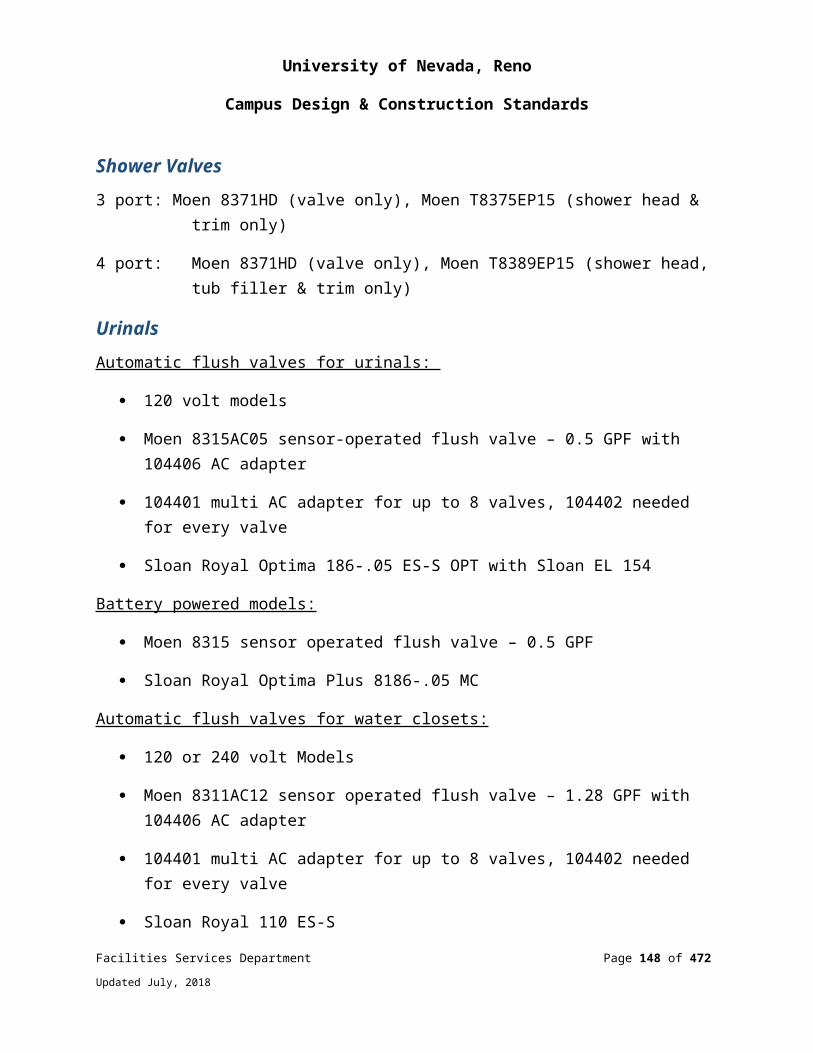
University of Nevada, Reno
Campus Design & Construction Standards
o ACIo Equal upon approval
Pressure Transmitters o Veriso Equal upon approvalo Exterior Sensors shall be Veris, Setra or equal upon approval. Veris PX
series shall be used for Air and PW series for wet application. Carbon Dioxide Sensors shall be silicon based NDIR single beam dual wave
length technologyo Vaisalao INTEC o Equal upon approval
Air Flow Monitoringo Ebtrono Equal upon approvalo Static Pressure Traverse Probe o Cleveland Controlso Equal upon approval
BTU Monitoring Devices o Sierra Instruments model series 640S gas mass flow meter (buildings not
on the HTHW loop)o Fluxus ADM 7407 by Flexim with either Modbus or BACnet
communication options (if the building heat is supplied by the campus HTHWS)
o SITRANS FUE1010 by Siemens which comes in Modbus or N2 communication protocols (if the building heat is supplied by the campus HTHWS)
o Belimo Energy Valveo Equivalent upon approval
Refrigerant Leak Detectors o Amseco Model CSHB-BG (with blue light lens)o MSA Instruments o Approved equal by Kele & Associates o Current Sensing Switches
Facilities Services Department Page 148 of 349
Updated July, 2018
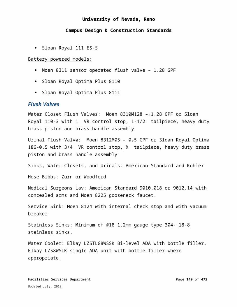
University of Nevada, Reno
Campus Design & Construction Standards
o Veris Industrieso Functional Deviceso Equal upon approval
Air Pressure Safety Switches o Penno Dwyero Equal upon approvalo Water Flow Switches & Low Temperature Limit Switcheso Penn P74o Equal upon approval
Electrical Power Monitoring Devices o Meters shall be Nexus series 1262.
Output DevicesApproved manufacturers
Actuators & Control Valveso Belimoo Equal upon approval
Control Relayso Ideco Equal upon approval
Miscellaneous Devices
Approved manufacturers
Variable Frequency Driveso ABBo Dan Foss
230910 – LABORATORY SYSTEMS - INSTRUMENTATION AND CONTROL FOR HVAC
SYSTEM DESIGN AND PERFORMANCE REQUIREMENTS
Facilities Services Department Page 149 of 349
Updated July, 2018
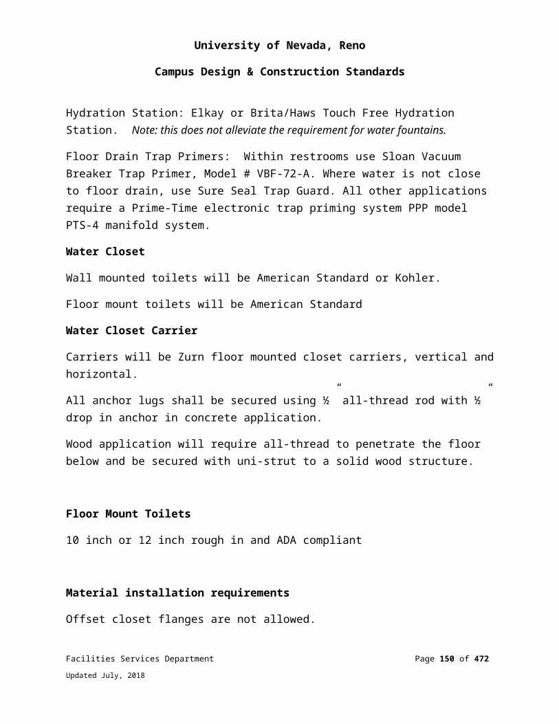
University of Nevada, Reno
Campus Design & Construction Standards
Variable Volume SystemsAll variable volume systems shall have an occupant sensor for each fume hood which will reduce the air flow to a minimum level when the hood is not in use.
For all variable volume systems, the fume hood shall have a local override control that will permit the operator to run the hood air volume to its maximum rate.
Variable air volume systems controllers must be integrated with the campus controls system, Automated Logic. The system shall provide BACnet interface capabilities.
Variable air volume systems shall have pressure independent airflow control valves suitable for up to 3” w.g. pressure drop.
Variable volume control system must react within 3 seconds to changes in air flow.
Fume Hoods Fume hood average face velocities shall be an average of 100 fpm, plus or minus 10%, at a design sash opening of 16” with no individual face velocity reading exceeding plus or minus 20% of the average face velocity. All hoods must be tested both in the factory and on-site in accordance with ASHRAE 110. Fume hood designs that demonstrate as installed containment with an average face velocity of less than 80 fpm, such as low flow constant volume hoods, can be considered with approval from Facilities Services and EH&S; however, average face velocities at the design sash position shall be at least 60 fpm. In addition to meeting the requirements of ASHRAE 110 as installed, hood field certification by EH&S is required before being turned over for service to the user.
All fume hoods shall have a flow indicator installed which has both an audible and visual alarm for low flows. The flow-measuring device shall be capable of indicating improper flow when the flow is 20% low, that is, 80% of the set point value.
All fume hood exhaust ducting shall be made from 16 or 18 gauge 316 stainless steel with screwed slip joint connections sealed with an appropriate sealant such as polysulfide. Facilities Services will determine if welded ‘TIG’ joints are required based on the laboratory materials and use planned for the fume hoods. (Type 316L must be used if welded joints are specified.) Additionally, Facilities Services will review alternate duct materials such as galvanized steel if proposed.
Facilities Services Department Page 150 of 349
Updated July, 2018

University of Nevada, Reno
Campus Design & Construction Standards
Fume hood exhaust shall not pass through un-ducted areas. Exhaust ducts shall always be at a negative pressure with regard to ambient.
All exhaust fans shall be located outside of the building on the roof or in a dedicated penthouse mechanical room with its own independent ventilation. All motors shall be outside of the duct and be of spark-proof design.
Laboratories with fume hoods shall maintain a slightly negative air pressure with regards to non-laboratory areas. Biosafety level 3 & 4 laboratories require a minimum of -0.03 to -0.05 w.g. differential between the laboratory and adjacent areas.
The fume hood and ducting shall have materials with a flame spread rating of 25 or less, per NFPA method 255.
Fume hood exhausts shall extend above the building roof at least ten (10) feet to prevent personnel exposure and re-entrainment unless modeling demonstrates a higher point of discharge. Air dispersion modeling shall be done for new installations with two or more fume hoods.
Fume hood exhausts should be located at least fifty (50) feet away from any supply air intakes.
Exhaust discharge velocities shall be 3,000 fpm to prevent personnel exposure and re-entrainment unless modeling determines a different value is required. This requirement does not negate the need to perform air dispersion modeling. Mixed-flow exhaust fans shall be considered in addition to centrifugal type fans.
Fume hood discharge air shall not be recirculated.
Biological safety cabinets and clean benches are not a substitute for laboratory fume hoods.
The minimum air changes for laboratories are six (6) air changes per hour (ACH) for occupied conditions and four (4) ACH for unoccupied conditions. Supply air is 100% outside air. Variable volume (and constant volume) systems should be designed to have some capability for additional ventilation rates beyond the design level. Facilities Services and EH&S will work with the design team on what additional capacity is feasible for each zone. For a single lab which is served by a single, dedicated make-up air unit and the cooling load cfm exceeds the required exhaust cfm, a make-up air
Facilities Services Department Page 151 of 349
Updated July, 2018
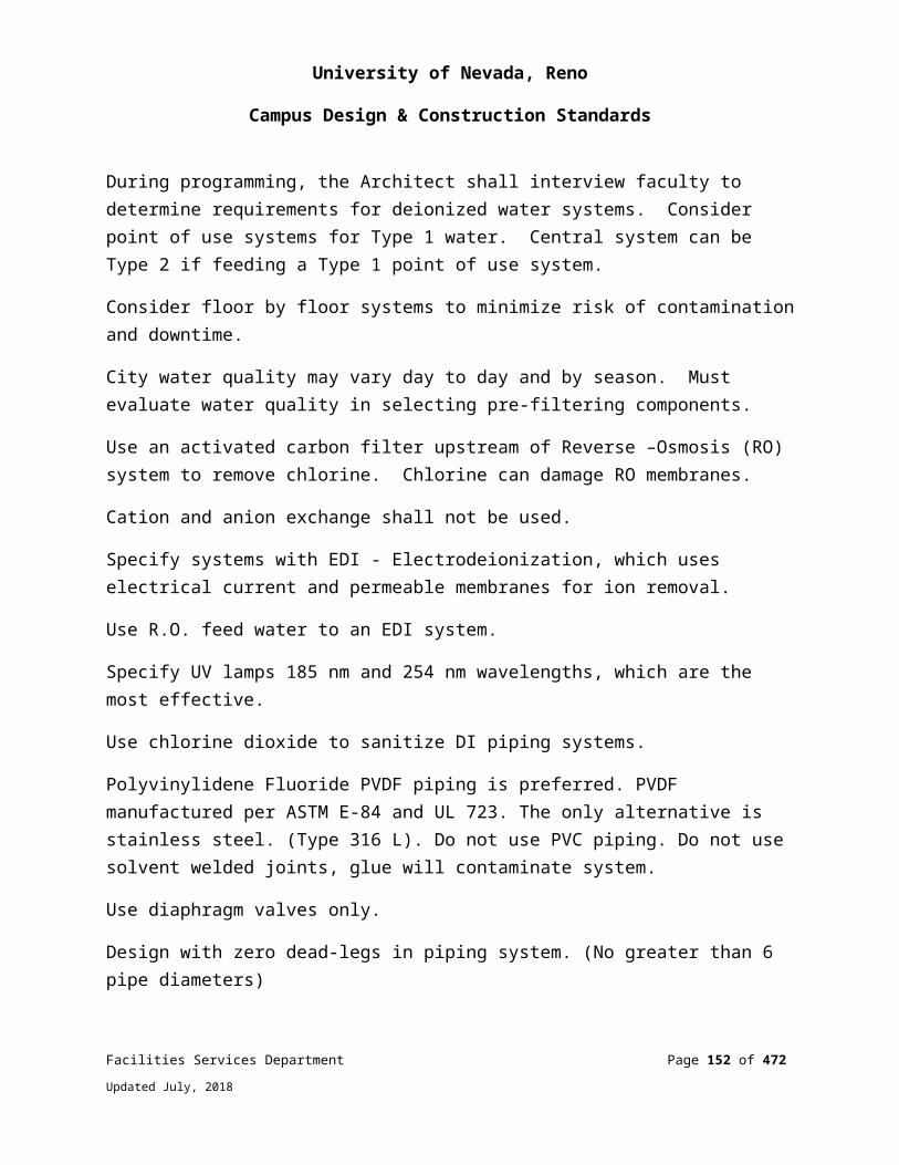
University of Nevada, Reno
Campus Design & Construction Standards
system with outside air and return air is acceptable provided that the six ACH minimum cfm rate required must be outside air. Any design for hood ventilation load diversity shall be approved by EH&S. Prior to applying any diversity, restrictions on future expansions or flexibility must be identified. Full-flow or very high-usage factor designs should be considered for laboratories with extremely high use patterns, such as teaching labs, or labs with high turnover.
Fume hoods shall not have automatic sprinkler systems or fire detection devices installed in them, unless specifically required by the authority having jurisdiction.
Heat recovery systems for room and/or laboratory fume hood exhaust shall be considered and a life cycle cost analysis should be performed to determine if the heat recovery system has a payback of ten (10) years or less. Heat recovery for fume hood exhausts shall be 100% cross contamination free between two air stream.
Fume hoods shall be located away from opening windows, doors and high traffic areas.
The fume hood shall be designed to contain minor spills. A ¼ inch lip or recess shall be provided within the hood.
Time clocks shall not be used to control fume hood exhaust or sash height.
All hood lighting shall be of UL-listed fixtures and meet NFPA 70, be of fluorescent type and be replaceable from outside the hood.
Sashes shall be made of laminated or tempered safety glass.
Dampers, when used in exhaust systems, shall fail open.
Room ambient air velocities directly adjacent to fume hoods shall avoid strong air currents. Ambient air velocities shall be less than 35 fpm as measured directly in front of the fume hood.
Perchloric acid hoods shall meet the requirements of NFPA Chapter 8 and be reviewed by EH&S and Facilities Services during the design phase.
Laboratory ventilation systems shall meet a noise criteria (NC) curve of NC 50 (approximately 55 dBA) at 3.2 feet, for research labs and NC 35 (approximately 40 dBA) at 3.2 feet for teaching labs.
Facilities Services Department Page 152 of 349
Updated July, 2018
University of Nevada, Reno
Campus Design & Construction Standards
Natural-gas, direct-fired make-up air units are not permitted for laboratory make-up (supply) air.
Used fume hood are not acceptable unless approved by EH&S.
Auxiliary supplied air hoods shall not be installed.
Ductless hoods shall not be installed in lieu of ducted hoods. Any design for ductless hoods must be approved by EH&S.
230933 - ELECTRICAL REQUIREMENTS FOR MECHANICAL EQUIPMENT
SYSTEM DESIGN AND PERFORMANCE REQUIREMENTSAll motors over 1/2 horsepower shall be premium efficiency type. Motors shall be open drip-proof (ODP), or totally enclosed fan cooled (TEFC) in high heat or high humidity locations. Minimum motor efficiencies at full load shall be as follows:
1.0 HP 86% 50.0 HP 94.1%
5.0 HP 89.5% 100.0 HP 95.1%
10.0 HP 91%
Those motors that will be controlled by a frequency drive shall be inverter rated. Any motor that could possibly have a frequency drive installed at a future date shall be inverter rated.
Ceiling mounted fan coils shall have a power disconnect switch mounted ON the cabinet on the same side as the filter access door. In addition the motor and V-Belt shall be accessible from the same side of the unit.
232100 – HIGH TEMPERATURE HOT WATER PIPING SYSTEMS WITHIN BUILDINGS
SYSTEM DESIGN AND PERFORMANCE REQUIREMENTSAll HTHW systems shall be engineered and tested in accordance with ANSI/ASME B31.1, Power Piping Code. A professional engineer registered in the state of Nevada
Facilities Services Department Page 153 of 349
Updated July, 2018

University of Nevada, Reno
Campus Design & Construction Standards
shall take full responsibility for HTHW system design by affixing his stamp to the drawings and specifications.
All piping, components and heat exchangers shall be rated for hot water service with continuous duty at 400 deg. F at 400 psig. See HTHW Heat Exchanger Piping Diagram Drawing #232116-3.
Piping located inside buildings shall be ASTM A53B Schedule 40 seamless type S or electric resistance welded type E, schedule 40 or wall thickness as determined by calculations per B31.1 Power Piping Code, whichever thickness is greater. Any piping that is threaded shall be ASTM A53B Schedule 80 seamless type S or type E. HTHW piping runs interior to buildings shall be kept to a minimum as needed to efficiently connect to the building’s heat exchanger.
In no case shall piping be smaller than ¾” diameter (NPS), unless otherwise specified.
Fittings shall be 300lb. ASTM A105 forged, socket weld for 2” and below. Above 2”, use butt-weld or 300# flanged carbon steel fittings meeting ASTM A234 WCB and ANSI B16.5. Gaskets shall be 316 stainless steel and graphite spiral wound by Flexitalic Type CG or approved equal.
Piping located inside a building shall be insulated with either fiberglass or calcium silicate. Calcium silicate shall be used at the direction of UNR anywhere there is the possibility of incidental contact due to maintenance activities or foot traffic. Jacketing shall be kraft-faced, fittings shall be pre-formed plastic, and the piping shall be labeled.
Expansion loops shall be used whenever feasible. If it is not feasible to use expansion loops, expansion joints may be used with authorization from FSD.
Isolation valves shall be rising stem gate with bolted bonnet, cast carbon steel body ASTM A216 WCB, 13% Cr stem and disc with satellite seat, ANSI Class 300 with raised face flanges, and high temperature graphite packing.
Control valves shall be globe type with cast carbon steel body ASTM A216 WCB, with stainless steel trim, ANSI Class 300 with raised face flanges, and high temperature graphite packing. Valves 2” and smaller shall be socket weld or flanged. Control valves shall seat tightly to class IV seat leakage sent leakage at a pressure equal to 110% of the design pressure of 400 psig and 400°. Actuators shall have a minimum 25% margin over valve seating torque. Provide a 1/3 and 2/3 modulating control valves on the high
Facilities Services Department Page 154 of 349
Updated July, 2018

University of Nevada, Reno
Campus Design & Construction Standards
temperature hot water return side and a two-way shutoff valve on the supply side. Valves to close on temperature in excess of 210 degrees F on the low temperature supply side and be manually reset.
Electric control and isolation valves in hthw piping shall be 300# flanged. Actuator shall be capable of shut-off against a 400 psi pressure differential. Valves shall include super capacitor accessory and shall be flowserve valtek gs316 stainless steel general service control valve or equal by rotork only, no other mfrs will be considered
Pneumatic control and isolation valves in hthw piping shall be 300# flanged. Actuator shall be capable of shut-off against a 400 psi pressure differential. Valves to be manufactured by Fisher or Leslie. No other manufacturers will be considered
Thermometers shall be installed in threaded 316 stainless steel thermowells installed in ¾” 300 lb. carbon steel threadolets. Thermometers shall be 4-1/2” dial, bi-metal type.
Pressure gages shall be no smaller than 4-1/2 dial. Isolation valves shall be installed between the line and the gage, and gages shall be selected such that the operating pressure falls between 40 and 50 percent of the full scale. Gage stems shall be no smaller than ½”. Liquid filled gages are not acceptable.
Branch Piping: Taps shall be made using 300 lb. Forged carbon steel ASTM A105 Grade B, ANSI B16.11 sockolets. No direct welding or use of half or full couplings is allowed. All branches shall utilize forged fittings, unless code calculations are provided.
All piping shall be seismically restrained as required by IBC, latest edition.
Piping shall be flushed prior to hydrotest. Contractor shall provide all temporary measures to facilitate flushing and testing, and shall provide a flushing and testing plan to the engineer for approval prior to flush or testing.
Product Standards and Manufacturers
Only piping fittings, valves and materials manufactured in the USA or Canada are acceptable.
232113 – HYDRONIC PIPING
Facilities Services Department Page 155 of 349
Updated July, 2018
University of Nevada, Reno
Campus Design & Construction Standards
SYSTEM DESIGN AND PERFORMANCE REQUIREMENTSProvide make-up water regulator, automatic isolation valve, flow meter, and pressure sensor for all closed loop heating and cooling hydronic systems.
Make-up water regulator to be set for proper system cold fill pressure as determined by the balancing contractor. Provide a full size bypass with manual isolation valve around the regulator to facilitate quick filling of the closed loop system.
Automatic isolation valve shall be a full port motorized ball valve installed to completely isolate the closed loop from the city water system.
Make-up water flow meter shall be monitored by the BMS. A sustained flow of water (GPM adj) for a pre-determined amount of time (adj) into the closed loop system shall cause the BMS to close the automatic isolation valve and generate an alarm to the operator.
A pressure sensor shall be installed at the point that the expansion tank is tied into the closed loop system (point of no pressure change). It shall be continuously monitored by the BMS and generate an alarm to the operator if the system pressure increases above or decreases below pre-determined set points (adj).
232120 - THERMAL ENERGY METERS
SYSTEM DESIGN AND PERFORMANCE REQUIREMENTSProvide a fully integrated thermal energy metering system to calculate BTU’s.
Ultrasonic clamp-on transit-time flow measurement: temperature measurement with clamp-on or insert temperature sensors.
System has an onboard memory to store energy trends
Quantities of measurement: Instantaneous thermal energy output, totalized thermal energy, volume and mass flow, temperature Ts,Tr,Td, flow velocity, liquid’s sound speed, signal strength.
PRODUCT STANDARDS AND MANUFACTURERSFluxus Btu Ultrasonic Meter
Facilities Services Department Page 156 of 349
Updated July, 2018
University of Nevada, Reno
Campus Design & Construction Standards
Approved manufacturer:
Flexim Americas Corp.250-v Executive Drive Edgewood, NY 11717 1-888-852-7473Approved Manufacturer Flexium
233113 - UNDERGROUND HIGH TEMPERATURE HOT WATER (HTHW) PIPING
SYSTEM DESIGN AND PERFORMANCE REQUIREMENTSHigh temperature hot water (HTHW) is the primary heat source for a variety of heating functions throughout the University. HTHW is generated at the Utility Plant and distributed via a loop piping system which operates at 325-375°F. Design conditions for piping are 400 psig and 400F.
PIPEASTM A-106 or A-53 type S (seamless) or Type E (electric resistance weld), Grade B, black carbon steel. Type F (furnace butt weld) is not acceptable.
Pipe Wall Thickness:
2 inch and smaller: Schedule 80
2.5 inch through 10 inch: Schedule 80
FittingsSocket Weld (2 inch and smaller): ANSI B16.11 forged carbon steel, ASTM A105, 2000 #class.
Butt Weld (2.5 inch and larger): ANSI B16.9, ASTM A234 WPB, extra strong.
Flanged (2.5 inch and larger): ANSI B16.5, ASTM A105 forged steel, 300 pound class, weld-neck flanges raised face.
Facilities Services Department Page 157 of 349
Updated July, 2018
University of Nevada, Reno
Campus Design & Construction Standards
Unions (2 inch and smaller): ANSI B16.11 forged carbon steel, 800 # class, socket weld ends.
All buried pipe fittings shall be butt welded for all sizes.
VALVESGeneral: Valves shall be socket welded for 1 1/2 inch and smaller piping, forged steel flanged or socket welded for 2” and larger. Flanged or butt welded for 2 ½ inch and larger. Acceptable valve manufacturers are provided below; no substitutions unless approved by the Project Coordinator. All rising stem valves shall have their stems coated with high temperature Nickle anti-seize after installation..
GATE VALVESSocket Weld (2 inch and smaller): ANSI B16.34, 800 pound class, forged steel, bolted bonnet, OS&Y, conventional port gate valve Walworth, Vogt, or Edwards.
Flanged (2 inch and larger): ANSI B16.34, 300 pound class, A216 WCB cast steel body, bolted bonnet, OS&Y, stainless steel trim; Walworth, Crane or Stockham.
Butt weld (2.5inch or larger): ANSI B16.34, 300 pound class, A216 WCB cast steel body, bolted bonnet, OS&Y, stainless steel trim, Walworth, Crane or Stockham.
GLOBE VALVESSocket Weld (2 inch and smaller): ANSI B16.34 800 pound class, forged steel body, stainless steel seat ring and plug, bolted bonnet, rising steam; Walworth, Vogt, or Edwards.
Flanged (2.5 inch and larger): ANSI B16.34 300 pound class, A216 WCB cast steel body, OS&Y, stainless steel trim, Walworth, Crane or Stockham.
ROTARY VALVES300 pound class, carbon steel, flanged, Adams or Keystone Vanessa. stainless steel seats.
Facilities Services Department Page 158 of 349
Updated July, 2018
University of Nevada, Reno
Campus Design & Construction Standards
Piping SpecialtiesGaskets: Non-asbestos containing ring gaskets, flexitallic type “cg” grafoil/304ss or equal, suitable for the fluids and temperatures encountered.
Bolting: ASTM A193, Grade B7, for bolts and studs, and ASTM A194, Grade 2H for nuts.
Sleeves: Sleeves for foundation wall penetrations shall be fabricated of one-eighth inch (1/8”) thick steel, with two inch (2”) wide collar welded in place, and the assembly hot-dip galvanized.
Wall Penetration Seals: High temperature elastomeric link type mechanical seals compressed with corrosion protected bolts and compression plates; Thunderline High Temperature Link Seal, no substitution; or fiberglass rope stuffed packing box if pipe or casing surface temperature exceeds 375 degrees F.
Expansion Joints (where permitted, expansion loops are preferred and shall be used wherever possible):
Expansion joints shall be slip tube type as designed for the specific location. They shall be 300 # rating, flanged, and shall conform to the Standards of the Expansion Joint Manufacturer’s Association.
Slip-tube type shall have external and internal high performance guides rated for 500°F and designed for packing under pressure; Yarway or Hyspan.
Slip-tube shall be single or double type with center take off taps as required for the given service.
Air Vents (for high points): ¾ inch, 300# steel gate valve is required at all high points and be located in accessible manholes. Discharge of air vents in vaults shall be routed to the floor with ¾ inch diameter steel pipe; use socket weld fittings. Install pipe nipple with threaded cap in outlet of valve.
Strainers: Y-type with cast or forged steel body. Cast steel 300# rated flanged ends or forged steel 300# socket weld ends; 1/8 inch mesh monel strainer elements, socket weld ends for 2 inch and smaller piping.
Facilities Services Department Page 159 of 349
Updated July, 2018

University of Nevada, Reno
Campus Design & Construction Standards
Pipe Hangers and Supports: Pipe hangers and supports shall be designed and located per the requirements of B31.1 and the recommendations of the powder insulation or prefabricated conduit system vendor.
Pressure gauges: 4.5 inch dial, bourdon tube, 0 to 500 psig, Ashcroft or equal. Include 300# forged steel needle isolation valve.
InsulationIn manholes, pipe 2.5 inch diameter and greater shall be insulated with ASTM C533, type I, calcium silicate; 2.5 to 6 inch diameter - 3 inches thick insulation, 8 to 12 inch diameter - 4 inches thick. Less than 2.5 inch diameter -1 inch thick.
In manholes, tunnels, and exterior installations: pipe and fitting insulation shall be covered with 0.016 inch smooth aluminum jackets with integral moisture barrier. Stainless steel band on 12 inch center shall hold the insulation to the pipe.
Valves and equipment shall be insulated with removable shop fabricated fiberglass padding rated for 500°F, with thin wire mesh lining, and covered with 18 ounce high temperature fiberglass cloth with Velcro straps.
ManholesAll structures shall be of reinforced concrete. Main line junctions and service connections shall be in vaults, which require two openings.
Prefabricated or field constructed manholes, where allowed, shall be provided with walls, floors, and roofs not less than 8 inches thick and reinforced with steel bars. Floors shall drain to sump hole.
Concrete shall be 4,000 psi minimum compressive strength after twenty eight (28) days, synthetic fiber, for both prefabricated and field constructed manholes. Air entrained admixture, 5 to 7% entrainment for all concrete exposed to effects of weather or freezing conditions.
Waterproofing shall be provided. Membrane waterproofing is preferred.
Steel ladders shall be provided.
Covers and openings shall be vehicular traffic rated (H-20).
Facilities Services Department Page 160 of 349
Updated July, 2018
University of Nevada, Reno
Campus Design & Construction Standards
Steel Pipe and Powder Insulation SystemThe powder insulation system shall provide for minimizing heat loss, corrosion protection, and unrestricted thermal movement between anchors.
Powder insulation shall be Gilsulate 500 XR. Thickness of the insulation shall be defined by the Engineer and shown on the Contract Drawings.
Expansion Loops and L-Bends: In addition to the powder insulation thickness, bends shall be preinsulated with ASTM C547, Class 1, mineral fiber to allow for thermal expansion of the piping. The mineral fiber thickness at bends should be approximately 200% of the calculated thermal growth.
Pipe Supports: Anchors shall be located outside vaults, typically at five feet from the vault wall. Anchors shall not transmit thrust loads to the manhole wall unless the manhole wall has been specifically designed for these thrust loads. Expansion loops shall use guides and vertical supports as required.
Buried Conduit SystemsCoated Steel Conduit Casing: Conduit casing shall be manufacturer’s standard drainable, ventable, and pressure testable system with an annular air space. Steel outer casing systems shall be epoxy coated. Perma Pipe Multi-Therm 500 or equal.
Conduit End Seals: Conduit end seals shall be fixed type where there is no thermal pipe expansion through the end seal and shall be slip type where there is thermal pipe expansion through the end seal. One-half inch (1/2”) threaded pipe ports at top and bottom of each end seal shall be provided for draining, venting, and pressure testing of conduit casings.
Insulation: ASTM C533, Type I, Calcium silicate, mineral fiber, or C552 cellular glass shall be used on the steel pipe within the casing.
Expansion Loops and L-Bends:ANSI B31.1 factory fabricated, with weld testing per design. Casing, couplings, insulation, and piping shall be identical to those used for straight runs and designed to ensure complete drainage. Fabricated materials shall be shipped to the job site in maximum feasible size sections to minimize number of filed joints.
Facilities Services Department Page 161 of 349
Updated July, 2018
University of Nevada, Reno
Campus Design & Construction Standards
Loop casings shall be sized to contain pipe movement without crushing the insulation or causing other damage. Eccentric reducers and increasers or welding collars designed to serve the same purpose shall be used to allow free drainage through the loop.
Pipe supports shall be slotted to permit unrestricted lateral movement of piping and shall be otherwise identical to pipe supports specified for straight runs.
Pipe Supports: Anchors shall be located outside vaults away from manhole wall. Inside vaults, vent and drain holes shall be provided at the top and bottom of casing closure plates.
Trenching, Backfilling, and CompactingTrenching: The University may limit the amount of trench to be opened at any time.
Bedding: Pre-insulated conduit systems: Ditch bedding shall be accurately graded with a minimum of six inches (6”) of sand. Sand shall pass a ¼ inch screen with not more than fifteen percent (15%) passing a No.200 sieve. Sand shall be backfilled to a minimum of six inches (6”) above the pipe casing. Bedding shall be laid to firmly support the piping along its entire length.
Steel pipe and powder insulation system: The steel pipes shall be top hung or bottom supported to allow a bedding of powder insulation underneath (in accordance with manufacturer’s specifications). The powder insulation shall be placed to the minimum thickness shown on the contract drawings. The insulation shall be installed and compacted (per manufacturer specifications) to firmly support the piping along its entire length.
Backfilling: Backfilling of trenches shall progress as rapidly as construction, testing, and acceptance of work permits.
Damage Repair: Utilities, wall, piping, and other improvements damaged during the course of work shall be repaired to their original condition or replaced by the contractor.
Excess Material: Excess material and debris shall be removed and disposed of, at an approved disposal site, within one week after final approval of installation.
Facilities Services Department Page 162 of 349
Updated July, 2018

University of Nevada, Reno
Campus Design & Construction Standards
Piping InstallationGeneralPiping and pipe systems shall be fabricated, assembled, welded; installed, and tested in accordance with ANSI B31.1
Piping shall be cut accurately to field measurements and worked into place without springing or forcing, except where cold springing is specified. Piping shall not be buried, concealed, or insulated until it has been inspected, tested, and approved in accordance with FIELD QUALITY CONTROL (below).
Materials and equipment shall be protected from the weather during construction.
Pipe runs underground between vaults shall be welded. Flanged and threaded joints shall not be buried.
Gaskets, packing, and thread compounds shall be suitable for the service. Joint compound shall be applied to male threads only.
Arrangement of all piping shall be shown on the drawings. During installation, care shall be taken to avoid interference with other piping, conduit, and equipment. Lines shall be trapped only where shown on the drawings.
Reducing fittings shall be used for changes in pipe sizes. Bushings shall not be used.
In horizontal lines two inches (2”) and larger, reducing fittings of the eccentric type shall be used to maintain the tops of the lines in the same plane.
Pipe shall be adequately supported and anchored so that strain from weight and thermal movement of piping is not imposed on piping, equipment, or structures.
CleaningEach section of pipe, fittings, and valves shall be thoroughly cleaned free of all foreign matter before erection. Interior of piping shall be cleaned thoroughly as described in Article 3.7 (below) before final connections are made.
Open ends of mains shall be plugged or capped during shutdown periods. Lines shall not be left open at any place where foreign matter might accidentally enter pipe.
Facilities Services Department Page 163 of 349
Updated July, 2018
University of Nevada, Reno
Campus Design & Construction Standards
Pipe Expansion: Expansion of pipes shall be accommodated by expansion loops, L-bends, Z-bends in buried locations, or by slip type expansion joints in manholes, tunnels and buildings. Expansion joints shall be set to ensure proper function and movement during system operation.
Connections: Locations of capped or plugged outlets for future connections shall be shown on the drawings. Weldolets or welding fittings shall be used for tapping existing system.
Line Drainage: HTHW lines shall be pitched to allow for drainage to the low point. Buried lines shall be pitched to accommodate the worst case of elevations and must be recorded on the as-built drawings.
WeldingResponsibilities of contractor for electric fusion welding:
Contractor shall be responsible for the quality of all welding.
Contractor shall be capable of performing all welding operations required for construction of the high temperature hot water distribution system.
Contractor shall determine the suitability of welding procedures used to ensure that welds meet the requirements specified herein.
Beveling: Field bevels and shop bevels shall be done by mechanical means or by flame cutting. Where beveling is done after flame cutting, surfaces shall be ground and thoroughly cleaned of scale and oxidation just prior to welding. Beveling shall conform to ANSI standards.
Butt welds: All butt welds shall be open root, multi-pass welds, 6010 or 6011 root with 7018 filler caps (SMAW welding process).
Electrodes shall be stored in a dry, warm area and kept free of moisture during fabrication operations. Electrodes that have lost part of their coatings shall be discarded.
Welds shall be inspected in accordance with ANSI B31.1 requirements. The University will radiograph 5 to 10% of the welds.
Facilities Services Department Page 164 of 349
Updated July, 2018
University of Nevada, Reno
Campus Design & Construction Standards
If any welds are found to be defective, the contractor is responsible for full 100% radiograph testing of all the welds. Repair of defective welds by adding weld material over the defect, or by peening shall not be permitted. Welders responsible for defective welds shall be re-qualified before performing more welding on the job.
All finished weld joints shall be painted with high temperature black paint.
Anchor Blocks:Anchor Blocks: Concrete anchor blocks shall be provided for pipe anchorage not less than five feet (5’) from building or manhole walls (except where metal anchor at the vault wall is shown on the contract drawings). Anchor blocks shall be cast against undisturbed earth using concrete that conforms to ASTM C-94 and has a minimum compressive strength of 4,000 psi at twenty eight (28) days.
Fabricated Structural Anchors: Fabricated structural anchors shall be provided if necessary in vaults, tunnels, and mechanical rooms as described in the contract drawings.
Wall PenetrationsGalvanized steel sleeves shall be provided for penetrations in concrete walls six inches (6”) or less in thickness and masonry walls. Existing concrete walls thicker than six inches (6”) shall be core drilled or equipped with galvanized steel sleeves. High temperature elastomeric link type seals shall be acceptable for use in all locations where the pipe temperature is 375 degrees F or less.
Insulation and Jackets:Insulation shall be continuous through pipe hangers with calcium silicate inserts to prevent crushing of insulation.
Valves and equipment in manholes and buildings shall be insulated and covered with removable jackets. Insulation shall stop short of bolts/studs at flanges to allow their removal without damage of permanent insulation.
No exposed insulation will be permitted. Metal end caps that match the insulation jackets shall be used to cover the ends of insulation runs.
Valve InstallationValves shall be installed in accordance with ANSI B31.1 and ASME Section VIII.
Facilities Services Department Page 165 of 349
Updated July, 2018
University of Nevada, Reno
Campus Design & Construction Standards
Valves shall be installed as shown on the drawings and as required for proper functioning of the system.
Valve handwheels shall be installed in locations accessible from floor level, preferably with vertical stems, for operation and repair.
All flange bolts shall be lubricated with a high temperature bolt lubricant approved by the project coordinator. Flanged bolt torqueing shall be in an incremental staggered pattern to assure even compression of the gasket.
Piping Special Ties Installation (Hangers and Supports)Hangers shall be sized to allow for continuous pipe insulation through the hangers. Hangers shall not be permitted to touch pipe.
Expansion bolts shall be acceptable for use in wall or ceiling construction.
Powder Insulation System InstallationInstallation of system to be done in strict accordance with the manufacturer’s specifications and design/installation manual. The contractor shall utilize the services of the manufacturer or manufacturer’s agent to oversee and approve the installation of the system at no additional cost to the University.
Buried Conduit Installation - Conduit Field JointsConduit sections shall be joined after leak testing of carrier pipe. Conduit joining materials provided or specified by the system manufacturer shall be used.
Pipe shall be insulated and casing joined to provide field joint equal to factory fabricated section on conduit system. Connections to existing conduit systems of a different manufacturer or type shall be made only in manholes or buildings and never in buried locations.
Conduit End Seals: Conduit end seals in manholes or tunnels shall be provided with goose neck vents on the top and drain valves on the bottom. In buildings, conduit end seals shall be provided with threaded brass plugs.
Field Quality ControlGeneral: The project coordinator or his representative will conduct field inspections and shall witness all field tests specified in this section. The contractor shall perform field
Facilities Services Department Page 166 of 349
Updated July, 2018
University of Nevada, Reno
Campus Design & Construction Standards
tests and provide labor, equipment, and incidentals required for testing. The contractor shall produce evidence, when required by the project coordinator, that any item of work has been constructed properly in accordance with the contract drawings and specifications.
Field TestsGeneral: All anchor blocks and restraints shall be complete prior to testing. Concrete supports shall be fully cured.
Piping Hydrostatic Pressure Tests:
Test pressure gauges for a specific test shall have dials indicating not less than one and one half (1-1/2) times nor more than two (2) times the test pressure.
Piping shall be flushed prior to hydrotest. Hydrotest at 600 psi for a 1 hr period, witnessed by University personnel. Contractor to provide all temporary measures to facilitate flushing and testing, and shall provide a flushing and testing plan to the engineer for approval prior to flushing or testing. After pressure testing, University personnel and the engineer must approve the completed piping system prior to insulating. At the discretion of the University, all welds that are not able to be hydrotested shall by x-rayed.
Cleaning: After pressure and hydrostatic testing, the pipe system shall be flushed with a water/chemical solution such as San Joaquin Chemicals, Inc. Sansolv 6103 or equal. The procedure, cleaning solutions, and disposal shall be approved by the project coordinator.
Operational Tests: After completion of the work, the system shall be operated for not less than six (6) hours at operational temperatures and pressure to demonstrate satisfactory function. The movement of each expansion joint shall be checked, and each valve shall be operated in both cold and hot conditions.
Product Standards and ManufacturersAll materials shall be certified new from factory. Pipe, and fittings shall be built in the USA or Canada to ANSI/ASME standards. Piping components made in other countries shall not be used unless specifically approved in advance by the Project Coordinator. Valves shall be made in the USA or Canada unless otherwise approved by the Project Coordinator.
Facilities Services Department Page 167 of 349
Updated July, 2018
University of Nevada, Reno
Campus Design & Construction Standards
Welder Qualifications: Welder(s) shall be qualified in accordance with ASME Boiler & Pressure Vessel Code, Section IX, Welding and Brazing Qualifications. Welders shall be thoroughly familiar with ANSI B31.1 requirements.
The Contractor shall furnish to the Project Coordinator all applicable welding procedures, individual welder certifications and procedure qualification records. All documentation shall be signed and dated by the appropriate contractor personnel.
Delivery and StorageContractor shall be responsible for inspecting materials delivered to site for damage.
Materials shall be stored on-site in enclosures or under protective coverings. Materials shall not be stored directly on ground.
Insulation, expansion joints, joint materials, fittings, valves, and gaskets shall be stored under cover out of direct sunlight.
HandlingPipe, conduit sections, fittings, valves and other accessories shall be handled in such a manner as to ensure delivery to the trench in sound, undamaged condition.
Special care shall be taken to avoid injury to coatings and linings on pipe and fittings. Damaged coatings and linings shall be repaired by the Contractor to the satisfaction of the Project Coordinator.
232500 – WATER TREATMENT
SYSTEM DESIGN AND PERFORMANCE REQUIREMENTSAll new hydronic water piping shall be initially cleaned before start-up of any equipment with Garratt Callahan closed loop cleaner #248L or equal.
Water treatment specialists shall be Garratt Callahan 50 Ingold Rd. Burlingame, Ca. All new water treatment chemicals shall be approved by the University of Nevada, Reno HVAC Maintenance Department prior to its introduction to the system.
Cooling tower water treatment must include the following:
Controller to be an Advantage LCFB -2E.
Facilities Services Department Page 168 of 349
Updated July, 2018
University of Nevada, Reno
Campus Design & Construction Standards
Chemical pump shall be Pulsatron Mod# LBO2SA-PTCI 24 GALLON a day for tower corrosion inhibitor, biocides will use Blue White Industries A100NX peristaltic pumps.
Make up and blow down water meters shall be Seamtrics WMP water meters with pulse capabilities.
Blow down valves shall be Blimo stainless steel ball valves and actuators.
Double wall containment tanks for chemicals and biocides only 5 gallon pails of biocides will be accepted.
Chemical pot-feeders shall be Griswald 5 gallon professional series with Griswald safety bar closure for both open and closed loops.
See detail drawings for standard design details
Corrosion Test Coupon Rack (Drawing # 232100-1) Injection Quill Detail (Drawing # 232100-2) for steam boiler installations.
233300 - DUCTS
SYSTEM DESIGN AND PERFORMANCE REQUIREMENTSAll new round ducting shall be spiral. All fittings shall be long radius unless otherwise approved.
Fiberglass duct is prohibited.
234100 – FILTERS
SYSTEM DESIGN AND PERFORMANCE REQUIREMENTSGeneral Air Handler ApplicationsPre- Filters: Standard efficiency pleated, media filters with average dust spun efficiency of 30 percent to 35 percent (MERV 8) when tested in accordance with ASHRAE 52.2-1999. Flanders 30/30 U/L class 2, 0.10” initial resistance at 300 FPM velocity.
Final Filters: High efficiency pleated media filters with average dust spun efficiency of 80 percent to 85 percent (MERV 13) when tested in accordance with ASHRAE 52.2 – 1999, Flanders U/L class 2, 0.30” initial resistance at 300 fpm velocity.
Facilities Services Department Page 169 of 349
Updated July, 2018

University of Nevada, Reno
Campus Design & Construction Standards
Standard Filter SizesThe following filter sizes are acceptable to use at the University Nevada Reno Campus. Sizes other than those noted below will not be accepted without prior approval from the Facilities Services Department.
1 inch x 12 inches x 24 inches (1”x12”x24”) 1 inch x 16 inches x 20 inches (1”x16”x20”) 1 inch x 16 inches x 25 inches (1”x16”x25”) 1 inch x 20 inches x 20 inches (1”x20”x20”) 1 inch x 20 inches x 25 inches (1”x20”x25”) 1 inch x 24 inches x 24 inches (1”x24”x24”) 2 inch x 12 inches x 24 inches (2”x24”x24”) 2 inch x 16 inches x 20 inches (2”x20”x24”) 2 inch x 16 inches x 25 inches (2”x25”x24”) 2 inch x 20 inches x 20 inches (2”x20”x24”) 2 inch x 24 inches x 24 inches (2”x24”x24”) 4 inch x 12 inches x 24 inches (4”x12”x24”) 4 inch x 24 inches x 24 inches (4”x24”x24”)
Furnish and install filter gauges as part of the DDC system. Assembly shall include an adjustable pressure transmitter with a 4-20 MA output signal for DDC interface.
Product Standards and ManufacturersManufacturer: Dwyer (No Substitutions)
233416- VARIABLE AIR VOLUME UNITS
SYSTEM DESIGN AND PERFORMANCE REQUIREMENTSDDC Interoperable variable air volume diffusers such as those manufactured by Acutherm Therma-Fuser model EM shall not be used. Any variable air volume diffusers specified shall be thermally powered such as Therma-Fuser model TF.
235200- HEATING HOT WATER BOILERS
SYSTEM DESIGN AND PERFORMANCE REQUIREMENTS
Facilities Services Department Page 170 of 349
Updated July, 2018
University of Nevada, Reno
Campus Design & Construction Standards
Hot water boilers shall be designed to provide 180 degrees F boiler water. Boilers shall be designed and constructed in accordance with ASME Boiler & Pressure Vessel Code Section IV and designed for 250 degrees F and 160 psig.
Boilers for critical use and/or emergency response facilities shall be dual fuel (natural gas and fuel oil) unless a variance is obtained or an alternate approach is approved by FSD. The secondary fuel (fuel oil) storage shall be for 24 hours maximum load and shall utilize in a double wall day tank located in the boiler room of 660 gallons or less per NFPA 30, of an exterior fiberglass or steel double wall storage tank either above-ground of buried type. All exterior tanks to have full instrumentation including interstitial monitoring and alarms and level reporting and alarm. Dual fuel boilers shall be equipped with electronic spark ignition for firing on fuel oil. Boiler flues for dual fuel boilers shall include a barometric damper at each boiler outlet.
Boiler types include steel vertical tubeless, scotch marine, fire box, fire tube and cast iron sectional. Selection shall be based on boiler horsepower requirements, available floor space and efficiencies. Boilers under 30 boiler horsepower can be cast iron sectional. Flex tube boilers are not permitted. A minimum of 5 square feet of heating surface per horsepower is required.
Burners shall be designed for a minimum 6:1 turndown.
The waterside pressure loss through the boilers at rated load shall not exceed 4psi. The boiler shall have a factory installed insulation with metal jacket. Minimum of 2” thick fiberglass or mineral wool insulation. Jacket to be 18 gauge, painted steel with heat resistant primer and finish coats.
Provide ASME safety valve(s).
Each boiler shall be equipped with a combination feeder and low water cut-off. Low water cut-off shall be float type with manual reset.
Each boiler shall be equipped with a manual reset type high temperature limit control.
Modular, gas-fired boilers for non-critical facilities up to 1,000,000 BTU/h are non-condensing type, copper fin tube, 85% minimum thermal efficiency. Units shall be forced draft with modulating burners.
Facilities Services Department Page 171 of 349
Updated July, 2018
University of Nevada, Reno
Campus Design & Construction Standards
The specifications for projects including a boiler shall require that the contractor apply for and obtain all required boiler inspections and operating permits (as required by the Nevada Industrial Relations Division, Occupational Safety and Health Enforcement Section, the contractor shall obtain an installation application prior to beginning any work and shall apply for a final inspection as required to obtain the boiler operating permit). Reference NRS 455C.
All new gas burners on boilers will have an IRI (Industrial Risk Insurers) approved gas train.
For applications where two boilers are to be installed, the boilers and associated pumps shall be enabled and disabled individually from the BMS. A single master controller that is a single point of control from the BMS shall not be allowed. Boiler status and alarms shall be hard wired to the BMS. Other points can be via BACnet.
235700 –HEAT EXCHANGERS
SYSTEM DESIGN AND PERFORMANCE REQUIREMENTSFor free cooling systems, a plate and frame heat exchanger shall be specified. Heat exchanger shall be sized for a 2 degree F approach, 304 stainless steel plates and nitrile, EPDM or BUNA N gaskets. Flanged connections to be150# ANSI raised faced flanges. Frames shall be epoxy painted carbon steel. Frame bolting to be stainless steel with carbon steel nuts. Provide in line conical stainless steel strainer. Upon startup the approach temperatures and differential pressures shall be documented and included in the balance report.
High temperature heat exchangers shall be shell and tube type: U-tube design, 2-pass with removable bundle, similar to Bell and Gossett HTWU. Refer to High Temperature Heat Exchanger Standard Detail in the Drawing 232116-3 for piping arrangement.
The high temperature side shall be the tube side with a 400 psig/400 deg. F rating, and the shell side shall have a 150 psig rating.
Provide a ¾ inch HX bypass with orifice plate where required by Facilities Services to provide a minimum bypass flow. Provide a flanged Y-strainer on HTHW supply side with ¾ inch drain valve.
Facilities Services Department Page 172 of 349
Updated July, 2018

University of Nevada, Reno
Campus Design & Construction Standards
All connections to be steel flanges using spiral wound, 300# gaskets, 316 ss/graphite. All flanges and valves to be 300# rating; cast steel valves 2 inches diameter and above and Class 800 forged steel less than 2 inch. All joints to be welded, no threaded joints except for instrumentation connections.
Exchangers shall be selected with a 0.0005 fouling factor.
Materials shall be steel shell, tube sheet, baffles, and tie rods, with 90/10 cupronickel tubes, 0.035 inches minimum tube thickness.
Provide ASME Code vessel complete with U-1 form.
Provide pressure relief on the shell side.
Specify a ‘Selco Seal’ steel trap heat exchanger head.
236400 –WATER CHILLERS
SYSTEM DESIGN AND PERFORMANCE REQUIREMENTSChillers shall comply and be tested in accordance with ARI 550/590. Pressure vessels to be in accordance with ASME B&PV Code Section VIII. Units shall be factory assembled including evaporator, condenser, compressor, lubrication system, refrigerant charge and controls/wiring. Chillers shall be UL listed.
The Engineer of Record shall analyze and recommend screw type water chillers or centrifugal chillers based on an energy analysis and IPLV (Integrated Part Load Value). Chillers over 300 tons rating to be centrifugal. Screw type chillers to be dual compressors with independent refrigeration circuits. Turbo Core magnetic bearing compressors are to be used whenever possible.
Condenser and evaporator tubs to be 0.035 inch wall thickness, copper. Condensers shall be cleanable, thru-tube types. 150 psig working pressure. Water boxes shall be removable. Tube side fluid velocity shall be 5 to 7 feet per second at full load.
Hermetic and semi-hermetic chiller drives shall have a five (5) year drive warranty that also includes refrigerant replacement in the event of drive failure and/or leakage. Open drives shall have squirrel cages, open drip-proof motors, induction type. All chillers to be factory tested to ARI standards.
Facilities Services Department Page 173 of 349
Updated July, 2018
University of Nevada, Reno
Campus Design & Construction Standards
The chiller shall have a graphic control panel with a standalone microprocessor to control the chiller. The display shall include the following:
Chiller liquid leaving temperature Chiller liquid entering temperature Condenser liquid entering temperature Condenser liquid leaving temperature Percent full load amps Operating Hours Input kW Evaporator pressure Condenser pressure Oil Sump Temperature Oil pressure
Chiller shall be able to run from 100% to 10% of full load. The controls shall have BACNet capability to interface with the campus control system: Automated Logic
Controls shall include an external unit stop pushbutton with indicating lights, oil safety switch, high and low pressure switches, water temperature controller, freeze protection thermostats, lock-out timer, compressor lead/lag switch, manual pump down switch and unloaders. The chiller shall also have local chilled water supply and return temperature gauges.
Screw chillers shall have independent refrigeration circuits and isolation valves.
Compressor drives shall be VFD drives.
Chillers shall be located in refrigeration machinery rooms per the Uniform Mechanical Code and a refrigeration monitoring system and evacuation system shall be provided.
236500 –COOLING TOWERS
SYSTEM DESIGN AND PERFORMANCE REQUIREMENTSComply with ASCE 7 for seismic supports of equipment (Seismic design requirements for factory assembled cooling towers).
Facilities Services Department Page 174 of 349
Updated July, 2018

University of Nevada, Reno
Campus Design & Construction Standards
Cooling TowersCooling towers are to be designed and constructed in accordance with the Cooling Tower Institute and CTI 201.
Cooling towers to be either cross flow or counter flow design, 2-cell, induced flow type designed for outdoor use, 304 stainless steel construction with PVC fill and mist eliminators. Low noise axial fan with V-belt drive. Towers systems to include conductivity controller and blow down valve. Where exposed to freezing conditions, cold water basin to have electric basin heaters. Sump temperatures, vibration cut-outs, and sump heaters to be monitored by the BMS. Each cell shall have independent fill piping and controls. Cells shall be capable of operating independently while the second cell is isolated for maintenance or repair.
Cooling tower basin shall be equipped with a basin cleaning system consisting of PVC piping and nozzles with automatic blowdown capabilities. A filtration system rated for 10% of condenser water system flow shall be provided with a pump that discharges to the basin cleaning system. Flame spread of all materials used shall be 25 or less.
The cooling tower, where required, shall have an OSHA-compliant handrail around the top and/or side where access is necessary and a cage ladder to all platforms.
Water Treatment Provide a chemical treatment system with tanks, pumps, piping and controls as outlined in section 232500. EPA approved dual biocides for microbiological control. The following criteria must be met: 1) Biological control of both bulk water and under deposit bacteria. The program components must be EPA registered as a biocide and be known to be effective against Legionella. Our maximum counts for open systems are 10,000 cells/ml or less for total aerobic; 50 cells/ml or less for anaerobic in the bulk water; and no Legionella. 2) Scale Control - This is normally accomplished with a combination of polymers & phosphonates. The LSI's should be calculated at various cycles and the program limitations identified. The highest skin temperatures are used in this calculation. 3) Corrosion Control - This is normally accomplished with a combination of the water’s naturally scaling tendencies (hardness + alkalinity) and then modified as necessary using phosphates, zinc, molybdenum, etc for mild steel. Azoles are used for copper corrosion control. Our acceptable corrosion rates are 1.0 mils/yr or less for mild steel and 02 mils/yr or less for copper. Provide for storage tanks, positive displacement
Facilities Services Department Page 175 of 349
Updated July, 2018
University of Nevada, Reno
Campus Design & Construction Standards
metering pumps and piping for two alternating biocides and two corrosion inhibitors on cooling tower condenser water circuit.
TestingBiweekly testing and written reports by the vendor for a period of one year from building occupancy, at no cost to the University, of condenser water with the following testing and data: conductivity, M alkalinity, pH, iron, copper, chlorides and microbiological counts (anaerobic and aerobic species and identification of species). Also, install steel, copper and galvanized steel (or 304ss) coupons in a 4- position coupon rack. Examine, weigh and replace coupons every ninety days. Also, the vendor must have a plan and demonstrate passivation of the cooling tower surfaces over a 90 day break-in period, if galvanized. At the end of one year of continuous services the vendor shall perform a borescope inspection of the chiller condenser bundle with photographs showing tube surfaces.
Corrosion Coupon Racks – All cooling towers shall have a four-position corrosion coupon rack, Betz-Dearborn # 2013971 PVC pipe and furnished with a flow meter, Dwyer Visi-Float VFC-142, 1-10 GPM range.
See drawings for other applications:
Drawing # 232100-1 Corrosion Test Coupon Rack Drawing # 232100-2 Injection Quill Detail for steam boiler installations.
237339 – MAKE UP AIR UNITS
SYSTEM DESIGN AND PERFORMANCE REQUIREMENTSMake-up air units shall be indirect gas-fired units with stainless steel heat exchanger. Modulating or staged burners required. UL and Factory Mutual listed. Air filters to meet MERV 8 or better.
Gas valves shall not be directly controlled by the BMS. Make up air units shall have their own standalone burner controls. The BMS shall only send set points or firing rate commands to the standalone burner controller.
Make-up air units shall not be controlled by BACnet communications. BACnet to be used for monitoring and information points only.
Facilities Services Department Page 176 of 349
Updated July, 2018
University of Nevada, Reno
Campus Design & Construction Standards
237400- AIR HANDLERS
SYSTEM DESIGN AND PERFORMANCE REQUIREMENTSRoof top air handlers shall be built in accordance with AMCA and ARI standards and shall be factory assembled and tested. The exterior casing shall be 22 gauge steel or better with 2” thick acoustic panels. Unit shall have a C-channel steel base and 14 gauge floor plate. Unit shall have fully gasketed access doors same thickness as walls. Minimum door dimensions are 24” x 72”. Finish shall be epoxy prime coat and acrylic finish. Centrifugal fans shall be steel or aluminum. Minimum bearing life to be AFBMA L-10 200,000 Hours.
Hot water and chiller water coils to be rated for 250 psig, 0.20” minimum wall and 5/8 inch tube diameter. Minimum 10 fins per inch copper coils with aluminum fins. Cooling coil racks to be 304 stainless steel. Chilled water coils to have minimum 12 degrees delta T. face velocity not to exceed 500 fpm. Provide compartment in unit for coil valving, accessible from outside the units via access doors.
Unit shall have disposable pre-filters, 4 inch thick, meeting MERV 6. Final filters to be MERV 13 or better. Strion electro-static filters shall be evaluated for large units. Provide sound attenuators in unit.
Fan-wall/fan-array technology shall be used unless the design requirements do not permit the application. Arrays shall not exceed 10 total fans.
Air handlers shall not be controlled by BACnet communications. BACnet to be used for monitoring and information points only.
237433 – ROOFTOP AND GROUND MOUNTED PACKAGED HEATING/COOLING UNITS
SYSTEM DESIGN AND PERFORMANCE REQUIREMENTSUnless specifically approved by the University, all rooftop and ground mounted packaged heating and cooling units shall be supplied with an outside air economizer section to provide free cooling complete with exhaust air to prevent over pressurizing the space. Dampers shall be full modulation with minimum position set to provide 100% or required ventilation air.
Facilities Services Department Page 177 of 349
Updated July, 2018
University of Nevada, Reno
Campus Design & Construction Standards
Heating sections shall be indirect natural gas fired with an electronic ignition system.
Cooling sections shall utilize either R-22 or R-410A refrigerant and use hermetic scroll compressors. Low ambient controls including but not limited to crankcase heaters, head pressure controls, low pressure cut-outs and manual reset high pressure cut-outs shall be included. Each refrigerant circuit shall include a thermostatic expansion valve (TXV) with removable power element.
Package units shall not be controlled by BACnet communications. BACnet to be used for monitoring and information points only.
238100 – HVAC EQUIPMENT: SPOT COOLING APPLICATIONS
SYSTEM DESIGN AND PERFORMANCE REQUIREMENTSFor high density cooling applications, such as computer/server rooms or other sensitive electronic equipment, that requires constant 24/7 cooling: the product allowed is Liebert precision air conditioning systems. For controls, a field supplied 3 or 4 wire connection, (24 VDC) is required between the evaporator and condenser. Control wiring must not allow a voltage drop in the line of more than 1 volt (16 gauge minimum for 75 feet). On a small system, the wall box is connected to the system’s microprocessor board using a four wire system. Wiring to be Belden shielded cable, 20-22 AWG up to 1,000 feet. The shield should be grounded at the evaporator unit.
In buildings with chilled water available a DX & CHW coil shall be installed. Onboard controls shall utilize chilled water if available and automatically switch to DX as needed.
UNITARY AIR CONDITIONERSWindow or wall mounted air conditioners are not acceptable. Where space cooling is needed and the building primary system cannot be used, split DX cooling systems with a remote condenser shall be used.
Unitary air conditioners shall not be controlled by BACnet communications. BACnet to be used for monitoring and information points only.
HVAC COMMISSIONING
Facilities Services Department Page 178 of 349
Updated July, 2018
University of Nevada, Reno
Campus Design & Construction Standards
Heating hot water, glycol, chilled water, and condenser water piping systems: work includes installation inspections and checks; pressure tests cleaning and flushing and documentation; expansion tanks; confirmation of flow balancing completion; seismic restraints installation certification.
Duct and air-handling systems: work includes installation inspections and checks; confirmation of flow balancing completion; leak testing as applicable; seismic restraints installation certification.
Chillers: work includes installation inspections and checks; seismic restraints installation certification; checkout and startup by manufacturer’s representative; documented performance measurements including capacity, evaporator and condenser flows, motor amperage, controls operation, and sound levels.
Cooling towers: work includes installation inspection and checks; seismic restraints installation certification; chemical treatment; checkout and startup by manufacturer’s representative in conjunction with chiller; documented performance measurements including sound, capacity, motor amperage, pan heater operation, sweeper system operation, makeup water, overflow, and capacity controls.
Closed-circuit heat rejecters or Evaporative Condenser: work includes installation inspection and checks; seismic restraints installation certification; chemical treatment; checkout and startup by manufacturer’s representative in conjunction with chiller; documented performance measurements including sound, capacity, motor amperage, pan heater operation, sweeper system operation, makeup water, overflow, and capacity controls.
Refrigeration compressor/condensing unit: work includes installation inspection and checks; seismic restraints installation certification; checkout and startup by manufacturer’s representative as specified; documented performance measurements including capacity, evaporator and condenser pressures, motor current draw, and controls operation.
Boilers: work includes installation inspection and checks; seismic restraints installation certification; boil out and chemical treatment; checkout and startup by manufacturer’s representative as specified; documented performance measurements including combustion efficiency, capacity test, burner and controls operation.
Facilities Services Department Page 179 of 349
Updated July, 2018
University of Nevada, Reno
Campus Design & Construction Standards
Pumps: work includes documented checks on alignment, rotation, motor current draw, flows and pressures.
Supply, Return, Relief and Exhaust Fans: work includes checks on installation; seismic restraints; dampers and other accessories; rotation, sound levels, motor current draw, and airflows and pressures.
Air Handling Units (both packaged and built-up): work includes installation inspections and checks; seismic restraints installation certification; checkout and startup by manufacturer’s representative as specified; documented capacity tests, for heating, cooling, air flow and static pressures; operation of all controls; sound level.
Air Terminal Devices: work includes installation inspection and checks; for VAV units, flow adjustments and calibration coordinated with controls and air balancing; controls operation including flow modulation, reheat, controls responses.
Fan-coil Units: work includes installation inspections and checks; performance and controls checks.
Water-source Heat Pumps: work includes installation inspections and checks; documented seismic installation certification; performance and controls checks.
Controls Air Compressor: work includes installation inspections and checks; documented seismic installation certification; operational checks.
Direct Digital Control System: work includes inspections and checks of installation and operation of all devices; complete operation of all controls sequences, in coordination with commissioning of all controlled systems.
Variable Frequency Drives/Motor controls: work includes inspections and checks of installation and operation of all devices; complete operation of all controls sequences, in coordination with commissioning of all controlled systems.
Facilities Services Department Page 180 of 349
Updated July, 2018
University of Nevada, Reno
Campus Design & Construction Standards
Facilities Services Department Page 181 of 349
Updated July, 2018

University of Nevada, Reno
Campus Design & Construction Standards
End of Division 23
HEATING, VENTILATING AND AIR CONDITIONING
Facilities Services Department Page 182 of 349
Updated July, 2018
University of Nevada, Reno
Campus Design & Construction Standards
DIVISION 26: ELECTRICAL 260000 - GENERAL
SYSTEM DESIGN AND PERFORMANCE STANDARDS
All work shall comply with the latest adopted versions of the National Electrical Code, National Fire Code, NFPA 70E, OSHA, International Building Code, State Codes, and University Campus Design & Construction Standards.
Design systems and select equipment to minimize or eliminate the risks of electrocution, arc-flash, and arc-blast hazards to maintenance and operations personnel. Refer to NFPA 70E, Article 130.1.
Work on energized electrical equipment shall not be done on UNR Campus. All systems shall be shut down before opening up equipment. The proper PPE shall be worn by those verifying that the equipment is not energized. Anyone not complying with these requirements is subject to dismissal and not being allowed to work on campus. For any complex Lock-out/Tag-out procedure as defined in NFPA 70E Article 120.2(D), contractors shall submit a method of procedure (MOP) when work inside existing panels, switchboards, transfer switches, transformers, etc., needs to be done. MOP shall contain all the information included in the example MOP in APPENDIX L Electrical Method of Procedure. MOP shall be submitted to the Facilities Services Senior Electrical Engineer for approval. Contractor shall not proceed with the work until the MOP is approved and a shutdown notice is in place.
All equipment shutdowns shall be coordinated with Facilities Services personnel. Notice of pending shutdown shall be submitted to Facilities Services in writing 2 weeks minimum prior to the shutdown. No shutdown shall take place without authorization and UNR Facilities Services personnel present.
VOLTAGESBuilding systems shall be 208Y/120 volt, 3 phase, 4 wire or 480Y/277 volt, 3 phase, 4 wire.
Choice of voltage and distribution systems shall be based on a study of the requirements of the building to determine which is the most economical.
Facilities Services Department Page 183 of 349
Updated July, 2018
University of Nevada, Reno
Campus Design & Construction Standards
DEMOLITION AND RENOVATIONDo not abandon equipment in place. All equipment not being reused shall be removed.
When equipment and/or devices are removed from service by being disconnected, remove the conductors and conduit back to the source. Conduits in concrete shall be cut flush with the floor and sealed.
Remove all labels not being reused.
All electrical equipment being removed shall be disposed of properly unless otherwise directed.
Update panel schedules for removed loads. Indicate ‘Spare’ on the schedule when wires are removed from a circuit breaker and ‘Space’ on open breaker spots.
Underground conduit shall be capped and attach an identification tag indicating conduit origin.
CLEARANCES AND LOCATIONSAll interior and exterior electrical equipment and equipment rooms shall be designed to ensure adequate clearances for service, maintenance, and removal/replacement of electrical equipment, panels, switchboards, transformers, generators, etc.
All electrical rooms shall only contain electrical equipment. No data equipment, no plumbing piping, no HVAC ductwork or piping, unless it is associated with the electrical room, are allowed in an electrical room.
All electrical panels, transformers, switchboards shall be installed in electrical rooms. Motor control centers shall be located in mechanical equipment rooms with the equipment that they serve.
Locate electrical equipment so it will be accessible for inspection, service, repair, and replacement without removing permanent construction, with working clearance and dedicated space as required by the NEC® and as recommended by the manufacturer.
For all medium voltage pad mounted transformers and switches 10’ minimum clearance is required in front of the doors and 3’ minimum clearance on the non-accessible sides. Maintain area for truck access and overhead clearance for removal by crane. Provide 3’ minimum concrete or asphalt apron around equipment pads. The 10’ minimum Facilities Services Department Page 184 of 349
Updated July, 2018
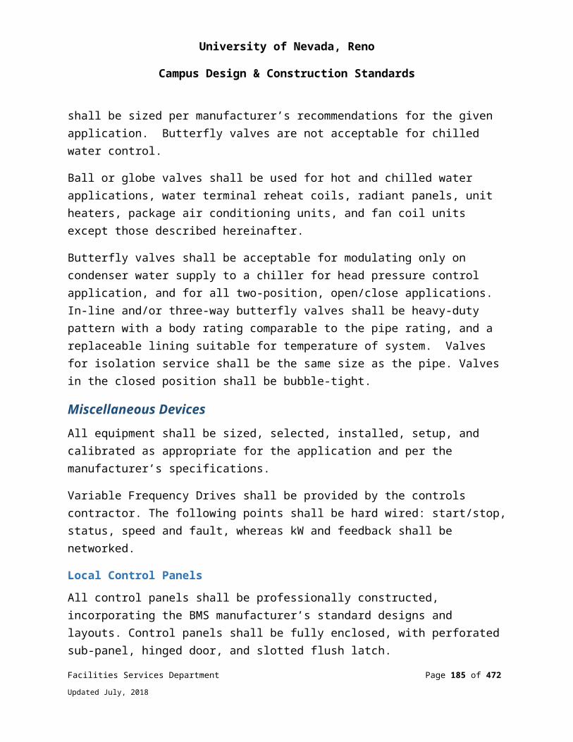
University of Nevada, Reno
Campus Design & Construction Standards
clearance in front of the equipment shall be flat, concrete, grass, decomposed granite or pea gravel.
WHEN DETERMINING GENERATOR SITE LOCATION CONSIDER THE FOLLOWING:Access for large fuel truck, load bank trailer and crane for removal.
Generator engine exhaust in relation to building air intakes and operable windows.
Landscaping - deciduous trees in close proximity to generator enclosure (debris gets sucked into radiator).
Snow, ice, rain shed from building.
Drainage from nearby cooling towers or roof drains.
Bird habitats.
3’ minimum clearance around generator for service.
Seismic Loads: All electrical equipment, light fixtures, etc. shall be securely anchored to resist earthquake loads.
CALCULATIONSElectrical calculations are required for all aspects of the electrical systems. Calculations shall be neatly prepared and organized so that an independent peer reviewer can readily check the validity and completeness of the analysis and design. All significant electrical components shall be validated by calculations. Computer programs used shall be identified by name and version number and the input results shall be clearly documented and presented.
The minimum calculations required for each project are:
Energy code compliance calculations Lighting calculations for all spaces (interior and exterior) Feeder voltage drop calculations (3% Maximum) Short circuit calculations Service load calculations (Per NEC) Coordination curves of the electrical system with protective devices used
Facilities Services Department Page 185 of 349
Updated July, 2018
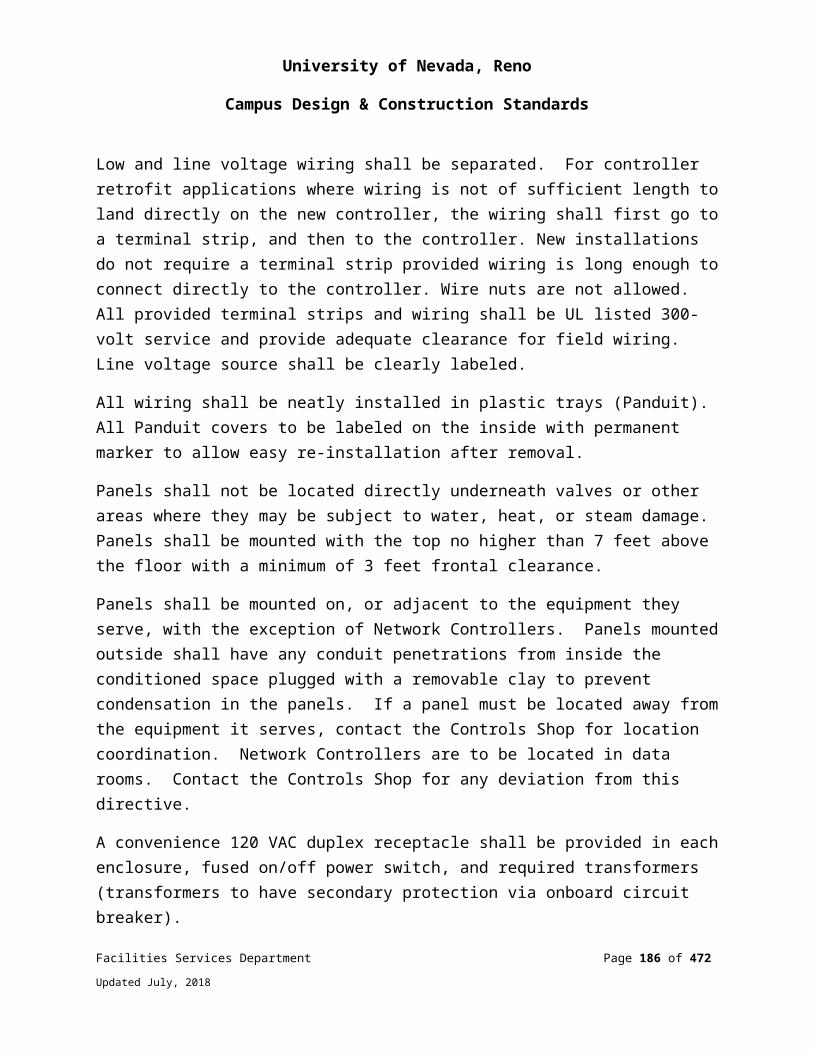
University of Nevada, Reno
Campus Design & Construction Standards
Arc Flash Study
TESTING OF ELECTRICAL SYSTEMSSpecifications shall include requirements for electrical system testing, including documentation of test results, as appropriate for the electrical systems utilized in the project. Electrical systems testing and documentation requirements shall be in accordance with a recognized testing standard such as those published by the International Electrical Testing Association (NETA).
260513 - MEDIUM VOLTAGE CONDUCTORS
SYSTEM DESIGN AND PERFORMANCE STANDARDSAll medium voltage conductors shall be MV-105 copper conductors, single conductor EPR (Ethylene Propylene Rubber) insulated with a black sun-light resistant polyvinyl chloride jacket rated 5,000 or 25,000 volts, and 133% insulation level. All MV conductors shall have copper tape shields.
All new campus distribution 25kV system conduit shall be 6” Schedule 40 PVC. Conduit shall be buried 3’ minimum to the top of conduit. Conduit shall be encased in 3” minimum envelope of 2500psi red concrete with #12 tracer wire. Warning tape shall be buried 1’ below finished grade above MV conduits.
All new 25kV line side conductors shall be 750kCM installed in 6” conduit.
Medium voltage conductor splices shall only be made with approval from a UNR representative. Splices, when allowed, shall be of the molded material type with conductor mating seal to provide a fully shielded and fully submersible splice. Splices shall not be made with taped splice kits.
Terminations for 600A MV conductors shall be bolted dead-break elbows and load-break elbows for 200A MV conductors and less.
The color code for medium voltage conductors shall be: A phase – red; B phase – yellow; C phase – blue.
Facilities Services Department Page 186 of 349
Updated July, 2018
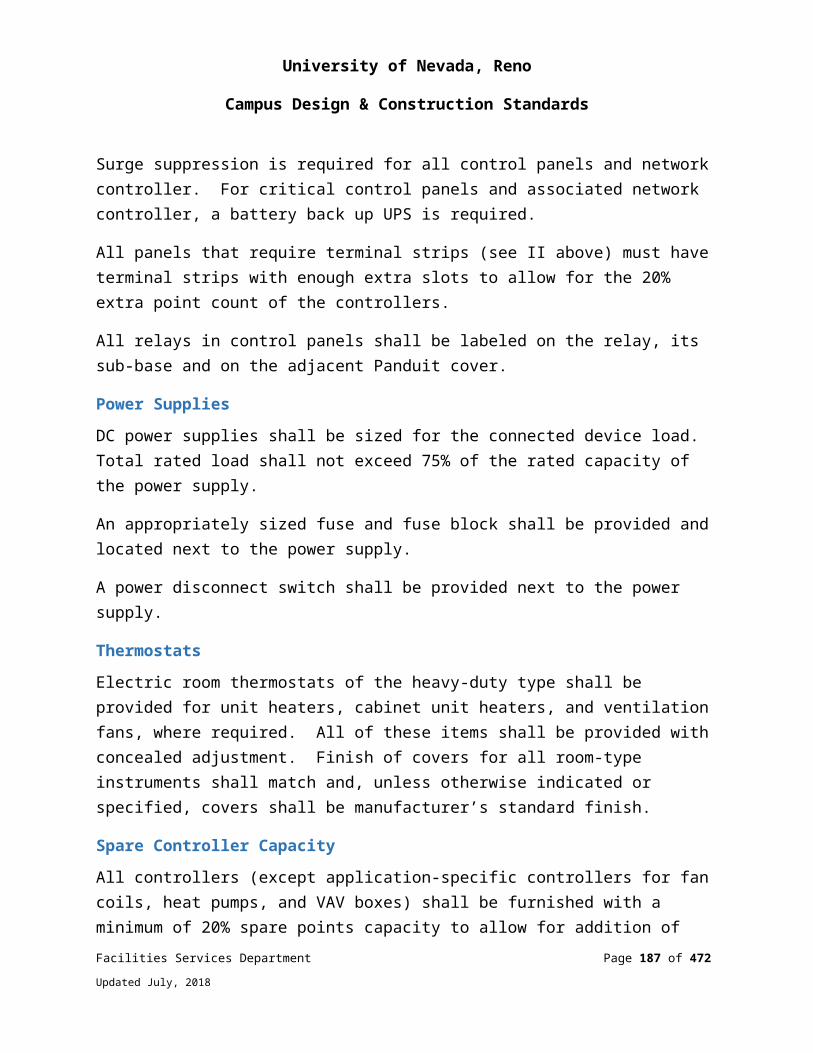
University of Nevada, Reno
Campus Design & Construction Standards
260519 - LOW VOLTAGE ELECTRICAL POWER CONDUCTORS AND CABLES
Conductor material shall be copper for all conductor sizes.
No wire smaller than #12 AWG shall be used for light and power circuits.
Provide full size separate color coded neutral conductors with a stripe that corresponds with phase color for all branch circuits. No shared neutral conductors on 120 volt and 277 volt circuits.
All conductors shall be stranded for #12 or larger.
All splices of branch circuit conductors shall be done with twist-on wire nuts or insulated mechanical terminations. Push-in terminations are not allowed.
All building interior power, telephone, signal and other wiring (whether plenum rated or not) shall be installed in raceways. Exception: 50V or less cables in a remodeled area where other methods are currently being utilized and approved by a UNR representative.
MC Cable shall not be used. Exception: For a fixture whip (6’ maximum length) from a junction box to (1) a recessed fixture above an accessible (lift-out tile) ceiling, or (2) a recessed fixture with at least 4 square feet of surface area in a non-accessible type ceiling, or (3) a receptacle mounted in a ceiling tile.
Instrument cable shall consist of twisted shielded pair or triads.
Color code for conductors as follows:
Phase 120/240 Volts Δ
120/208 Volts Y 277/480 Volts Y Isolated Ground
A Black Black Brown Contrast Stripe
B Red with Orange Stripe for stinger leg
Red Orange Contrast Stripe
Facilities Services Department Page 187 of 349
Updated July, 2018
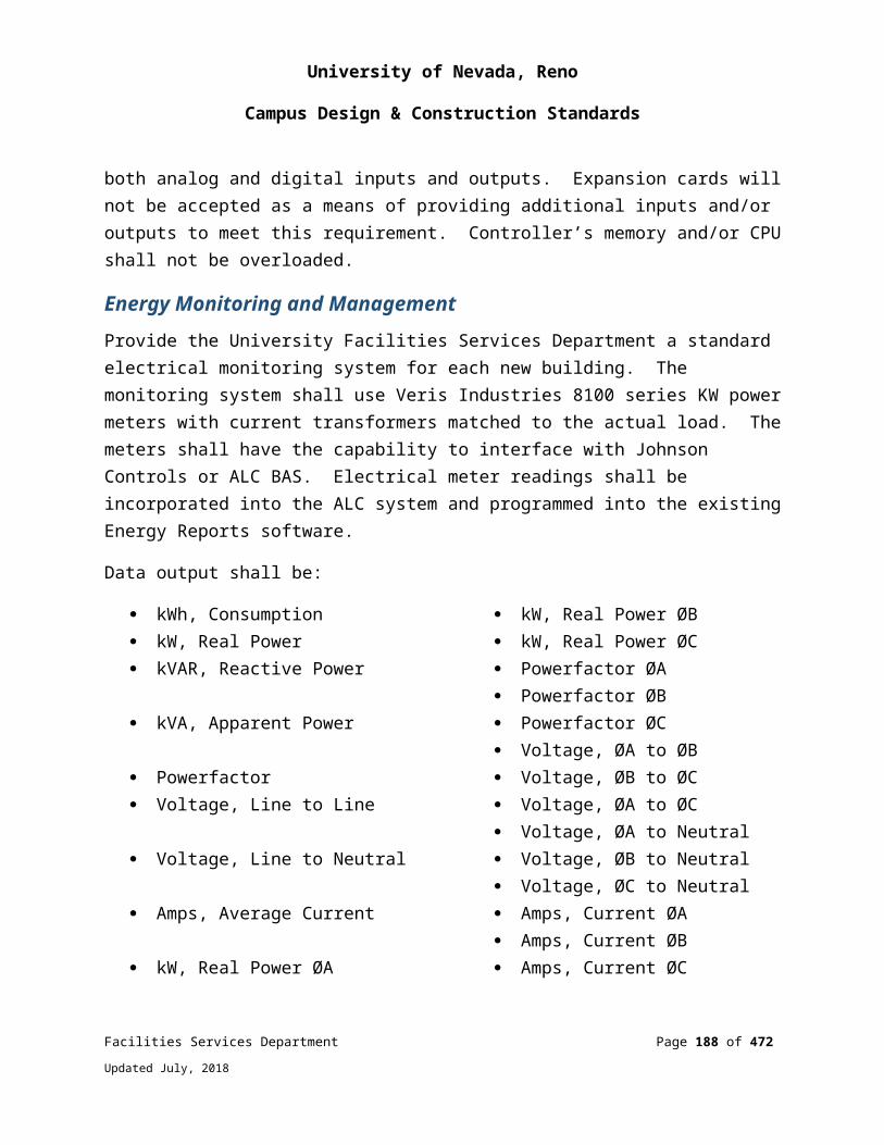
University of Nevada, Reno
Campus Design & Construction Standards
C Blue Blue Yellow Contrast Stripe
Neutral White with constant phase colored strip
White with constant phase colored strip
Gray with constant phase colored strip
Contrast Stripe
Equip. Ground Green Green Green Contrast Stripe
Note: On a delta connected, three-phase, four-wire system, the “high-leg” shall be connected to “B” phase and identified orange.
260526 - GROUNDING AND BONDING FOR ELECTRICAL SYSTEMS
SYSTEM DESIGN AND PERFORMANCE STANDARDSGrounding System Resistance shall be five ohms or less.
All medium voltage duct banks shall contain a minimum #2/0 bare stranded copper conductor. Connect this conductor to other grounding conductors and/or grounding electrodes.
Drive a 3/4” x 10’ ground rod in the bottom of each medium voltage vault. Connect grounding conductors and metal framing for vault lids to ground rod.
Every feeder and branch circuit raceway shall contain an equipment grounding conductor.
Proper grounding shall be provided for all electrical systems, including bonding connections at service entrances, metal piping, structures, panel boards, transformers, etc.
Do not rely solely on ground-rods for system grounding electrodes. A concrete encased 3/0 copper grounding electrode 30’ in length shall be installed per NEC for each electrical service.
All circuit grounds shall be made up such that a continuous path is reliably maintained to a grounding electrode or system.
Facilities Services Department Page 188 of 349
Updated July, 2018

University of Nevada, Reno
Campus Design & Construction Standards
Special consideration shall be given to grounding of sensitive office equipment (computer data circuits, etc.).
Provide a building ground ring attached to building steel at corners and then at no more than 100-feet separation when required by a lightning protection system.
Provide code acceptable isolated grounding for computer and communications room.
Utilize ground pads for termination of grounding conductors.
Configure emergency generator systems as separately derived systems.
Cable or electrode connections shall be exothermic.
260533 - CONDUIT AND RACEWAY SYSTEMS
SYSTEM DESIGN AND PERFORMANCE STANDARDSFittings for electrical metallic tubing shall be steel, watertight, gland-ring types or steel setscrew types.
All metal conduit, couplings, elbows, and fittings buried below grade shall be coated with PVC or 1/2-lap wrapped with an approved tape (coating or wrapping shall be a 20 mil total thickness). In lieu of rigid galvanized conduit for horizontal secondary service raceways and branch circuit wiring in or under a floor slab, Schedule 40 PVC may be used with rigid steel conduit termination stub-ups out of the ground or slab and into the building.
Electrical PVC conduit shall not be installed inside buildings.
Conduits located in concrete slabs shall not exceed 3/4” and shall be spaced no closer than eight inches on center except at panel and junction boxes where they shall be spread as widely as possible. Provide for special framing when required where conduits enter a panel board. In cases where conduits larger than 3/4” are to be placed in a concrete slab, the structural engineer shall be notified/consulted.
For irrigation systems provide a 1” conduit from the valves to the irrigation controller. Provide a pull string for future use.
Facilities Services Department Page 189 of 349
Updated July, 2018
University of Nevada, Reno
Campus Design & Construction Standards
Use flexible steel conduit (3’maxium length) in the following applications and install a code sized ground wire:
Motor connections. Connection between fan plenum and structure. Expansion joints with an accessible junction box on each side. Transformers, motors and other equipment that produce vibration.
For recessed lighting fixtures in an accessible (lift-out tile) ceiling flexible steel conduit shall not exceed 6’.
In existing walls, flexible steel conduit shall be allowed to fish down the wall to a new outlet location. A junction box shall be installed at the top of the wall.
At damp and wet locations or where exposed to weather, flexible steel conduit, where allowed, shall be liquid tight type.
All fire alarm system conduit shall be manufactured red.
260553 - IDENTIFICATION FOR ELECTRICAL SYSTEMS
SYSTEM DESIGN AND PERFORMANCE STANDARDSAll labeling shall be done by machine. No hand-written labels.
Provide labels on the covers for outlets, switches and junction boxes. These labels shall be engraved or created with a label maker using a high-quality label tape. Labels shall indicate panel and circuit numbers.
Provide identification for the systems and equipment shown on the drawings and/or specifications.
Types of electrical identification include:
Conduit Labeling Buried Cable and Conduit Labeling Cable/Conduit Identification Operational Instructions and Warnings Danger Signs Equipment/System Identification Labels and Signs
Facilities Services Department Page 190 of 349
Updated July, 2018

University of Nevada, Reno
Campus Design & Construction Standards
All Equipment/System/Panel Identification Labels shall include a room number, voltage, destination, and origin. Labels shall be engraved type with white letters on black for normal power, white letters on red for emergency power, and white letters on orange for UPS power.
Examples: At Panel 5L the label would contain the following information:
PNL 5L 208/120V 3P 4W Fed from DPL1 Located in Rm. E100
At Feeder Circuit Breaker in Distribution Panel DPL1 the label would contain the following information:
Feeds PNL 5L Located in Rm. E500
Provide the following types of identification on all electrical equipment as required by the NEC®, and NFPA 70E:
Arc-flash and shock hazard-warning labels Component identification Equipment nameplates Diagrams and Operating Instructions Emergency System Equipment Identification Warning Signs, Markers, & Device Labels
Single Line Diagram: Provide a one line diagram under a Plexiglas cover in the main electric room of any new or renovated building showing room, locations of panels and equipment. See Drawing # 260620.23-1 Sample Single Line Diagram – Electrical.
Warning Signs and MarkersInstall warning signs that conform to ANSI Z535.2 and meet the intent of the OSHA and NEC® danger and caution specifications on electrical equipment containing hazardous voltages (e.g. switchgear, switchboards, transformers, motor control centers, panel boards, starters, safety switches, busways, pull boxes, and cabinets).
Install voltage markers on electrical equipment (e.g. switchgear, transformers, motor control centers, panel boards, starters, safety switches, pull boxes, cabinets, etc.).
Facilities Services Department Page 191 of 349
Updated July, 2018

University of Nevada, Reno
Campus Design & Construction Standards
Install wire markers on power, control, instrumentation, fire alarm, and communications circuit wires.
Arc-Flash & Shock-Hazard Warning LabelsInstall arc-flash and shock hazard-warning labels that comply with ANSI Z535.4 on switchgear, switchboards, transformers, motor control centers, panel boards, motor controllers, transfer switches, generator panels, safety switches, industrial control panels, and other electrical equipment that is likely to require examination, adjustment, servicing, or maintenance while energized.
Locate the marking to be clearly visible to qualified persons before examination, adjustment, servicing, or maintenance of the equipment.
Note: Refer to Section 110.16 in the NEC®.
On renovation projects, install arc-flash warning labels on existing equipment where lock-out/tag-out will be required for the renovation work.
Note: Refer to NFPA 70-E, Articles 120 and 130.
Provide the information listed below on each label. Specify that arc-flash warning label information be produced by the electrical equipment manufacturer or supplier as a part of the final power system studies to be submitted by the Contractor in accordance with the electrical acceptance testing.
Note: In addition to the final arc-flash analysis, the final power system studies include load flow and fault-current calculations, and an overcurrent protective device (OCPD) coordination study based on the actual equipment to be installed for the project.
Information to be determined and applied to electrical equipment:
Arc-Flash Protection Boundary Arc-flash incident energy calculated in accordance with IEEE Std 1584a™ Working distance calculated in accordance with IEEE Std 1584a™ NFPA 70E Hazard / Risk Category Number or the appropriate personal
protective equipment (PPE) for operations with doors closed and covers on.
An abbreviated warning label may be used where it has been determined that no dangerous arc-flash hazard exists in accordance with IEEE 1584a™, paragraph 9.3.2.
Facilities Services Department Page 192 of 349
Updated July, 2018
University of Nevada, Reno
Campus Design & Construction Standards
Use a “DANGER” label where the calculated arc-flash incident energy exceeds 40 cal/cm.
260913 - ELECTRICAL POWER MONITORING AND CONTROL
SYSTEM DESIGN AND PERFORMANCE STANDARDSProvide University of Nevada, Reno standard monitoring system for each new building. The monitoring system shall use Electro Industries Nexus Series 1262 power meters with current transformers matched to the actual load. The meters shall have N2 buss capability and ModBus RTU selectable to interface with the campus controls system. Connect meter to campus controls system for data monitoring and collection. Verify that meter is calibrated and can be seen on the campus controls system.
Data Output shall be:
kWh, Consumption
kW, Real Power
kVAR, Reactive Power
kVA, Apparent Power
Powerfactor
Voltage, Line to Line
Voltage, Line to Neutral
Amps, Average Current
kW, Real Power ØA
kW, Real Power ØB
kW, Real Power ØC
Powerfactor ØA
Powerfactor ØB
Powerfactor ØC
Voltage, ØA to ØB
Voltage, ØB to ØC
Voltage, ØA to ØC
Voltage, ØA to Neutral
Voltage, ØB to Neutral
Voltage, ØC to Neutral
Amps, Current ØA
Amps, Current ØB
Amps, Current
Facilities Services Department Page 193 of 349
Updated July, 2018
University of Nevada, Reno
Campus Design & Construction Standards
261219 - PAD-MOUNTED, LIQUID FILLED, MEDIUM-VOLTAGE TRANSFORMERS
SYSTEM DESIGN AND PERFORMANCE STANDARDSAll service transformers shall be outdoor pad mounted transformers, shall be oil filled, radial feed configuration and shall be TP-1 or energy star rated. Each transformer shall be labeled with primary and secondary voltage, kVA rating and where it is fed from.
Provide a driven 5/8” x 10’ ground rod on the secondary side of each pad mounted transformer and attach to neutral terminal of the secondary side of the transformer.
Transformers shall be protected with steel bollards from damage by vehicles. Bollards shall be spaced to allow full access in front of equipment doors.
Provide a pet cock or valve located on the exterior of the transformer for oil sampling in an attached separate enclosure.
261319 - PAD MOUNTED, MEDIUM VOLTAGE, VACUUM INTERUPTER SWITCHES
SYSTEM DESIGN AND PERFORMANCE STANDARDSAll medium voltage pad mounted switches (PMS) shall be rated at 25kV, 600 amps. PMS shall be provided with 600A load interrupter switches, 200A fault interrupter switches, microprocessor-based overcurrent control, three-pole switching, three position switch (closed-open-grounded), vacuum fault interrupters for fault clearing, welded stainless steel tank, viewing windows, gas gauge, voltage indicator with LCD, SFG insulation and weatherproof hinged green enclosure. S&C Vista series – no exceptions.
PMS shall be installed on top of Jensen precast #612-7-F vaults for four-way PMS and #612-7-G for six-way PMS.
Install ten foot by ¾ inch ground rod in bottom of vault. All grounding and bonding conductors shall be mechanically bonded to ground rod.
Switches shall be protected with steel bollards from damage by vehicles. Bollards shall be spaced to allow full access in front of equipment doors.
Facilities Services Department Page 194 of 349
Updated July, 2018
University of Nevada, Reno
Campus Design & Construction Standards
262200 - LOW VOLTAGE TRANSFORMERS (600V OR LESS)
SYSTEM DESIGN AND PERFORMANCE STANDARDSAll indoor transformers shall be dry type NEMA TP-1, Class 1 rated with copper windings, 220-degree C UL-component-recognized insulation system with a maximum of 115 degree rise above 40 degrees C ambient temperature.
All transformers sizes 30 kVA and higher shall be floor or mounted. Sound levels shall be low not exceeding NEMA ST20 standard sound levels. All transformers shall be provided with vibration isolation. Isolation devices shall be designed for the equipment and shall retain their isolation characteristics for the life of the equipment. Each transformer shall have a manufacturer’s nameplate and a separate label indicating where it is fed from and required clearance from the wall.
Transformers manufacturers shall be consulted to obtain accurate heat generation data (on indoor transformers) which shall be coordinated with the mechanical engineer.
262400 - PANELBOARDS, DISTRIBUTION BOARDS, MOTOR CONTROL CENTERS
SYSTEM DESIGN AND PERFORMANCE STANDARDSAll distribution boards, motor control centers, and branch circuit panels shall have a minimum of 10% spare positions and not less than 6 spare poles.
Where panels are installed flush with the walls, empty conduits shall be extended from the panel to an accessible space above and below. A minimum of one 3/4 inch conduit shall be installed for every three single pole spare circuit breakers or spaces, or fraction thereof, but not less than two empty conduits.
Each interior building main disconnecting means shall be provided with a trip coil and exterior shunt trip switch identified with a red triangle. Location shall be coordinated with the fire authority.
A minimum of two levels of harmonic suppression shall be provided. One level at the main switchboard and the second level at each downstream distribution panelboard.
All circuit breakers shall be bolt-on type. All circuit breakers shall be 100% rated. No series rating allowed.
Facilities Services Department Page 195 of 349
Updated July, 2018
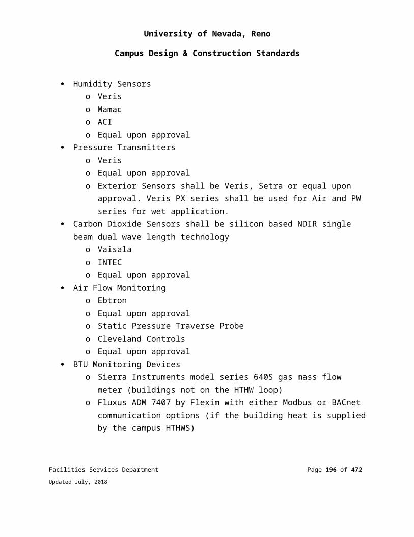
University of Nevada, Reno
Campus Design & Construction Standards
All panel board covers provide full height hinged trim integrated into the front cover to allow access to wire ways without removal of cover (door in door type).
Where underfloor space is accessible, spare conduits shall be extended there in addition to the ceiling space.
Panels shall have a typewritten directory giving circuit numbers and a complete description of all outlets controlled by each panel circuit breaker including room numbers.
All bussing for panel boards, distribution boards, and motor control centers shall be copper.
262419 - MOTOR APPLICATIONS
For HVAC motors over 10 HP and without VFDs, use solid state, reduced voltage starters. Starters shall have solid state adjustable heaters and provide protection for phase loss/reversal, over/under voltage, and shall have selectable trip classes (10, 20, and 30).
All motors larger than 1/2 horsepower shall be high efficiency type. Minimum motor efficiencies at full load shall be as follows:
1.0 HP @ 86%
5.0 HP @ 89.5%
10.0 HP @ 91%
50.0 HP @ 94%
100.0 HP @ 95.1%
262726 - WIRING DEVICES
SYSTEM DESIGN AND PERFORMANCE STANDARDSAll wiring devices shall be heavy duty specification grade.
All general receptacles and wall switches shall be 20A rated.
All corridors or hallways shall have duplex receptacles spaced not over 30 feet apart.
Facilities Services Department Page 196 of 349
Updated July, 2018
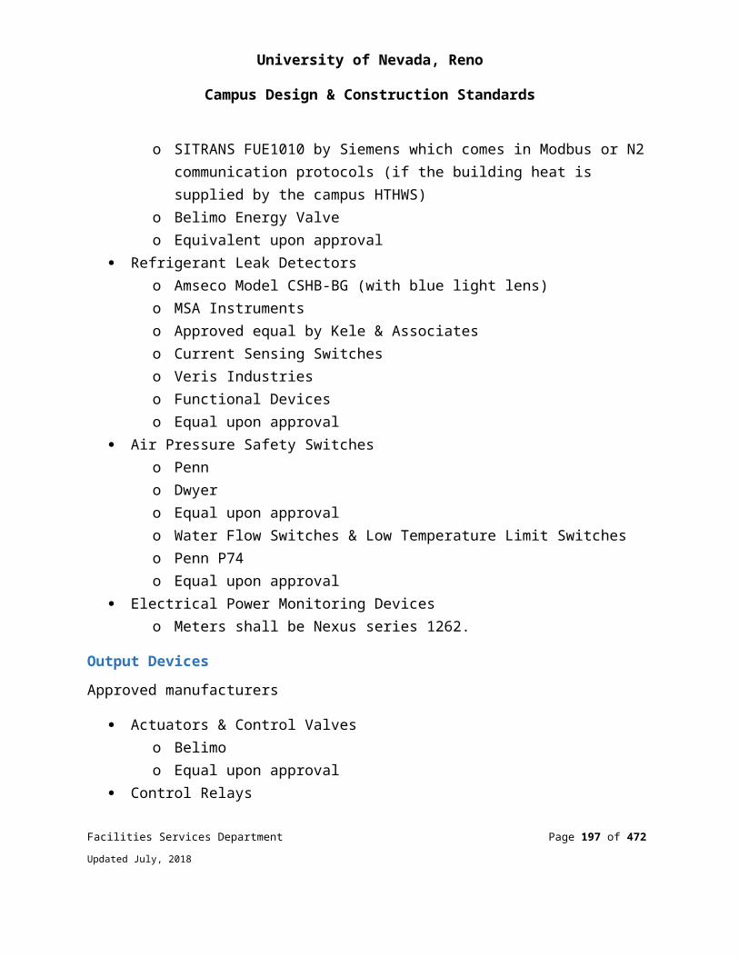
University of Nevada, Reno
Campus Design & Construction Standards
Outlet boxes, covers, rings, or other fittings shall be galvanized steel.
Sinks: When receptacles are installed within 1.8 m (6 ft.) of the outside edge of any sink, this includes laboratory sinks, they shall be GFCI protected.
Spacing: In office spaces a minimum of one duplex receptacle per wall.
Mounting heights of all electrical outlets shall be 24” AFF (top of box) unless noted otherwise.
Mounting heights of all switch plates shall be 42”AFF (top of box) unless noted otherwise.
Electrical outlets, switches, and all other controls required to be accessible shall only be mounted at heights inside these reach ranges (24” – 42” AFF) unless specifically justified and approved by Facilities Services Department (but in no circumstances shall they exceed reach ranges permitted by ARTSI A117.1 guidelines).
Wall switches near doors shall be mounted not more than 12 inches from the trim on the latch side of the door.
Gang type plates shall be used for multiple gang boxes.
Outside gathering areas shall have two dedicated 20 ampere 120 volt circuits installed in weatherproof lockable enclosures with a 20 ampere duplex GFCI receptacle for each circuit.
All devices shall be hard wired. No push-in or plug-in connections allowed.
All device plates shall be unbreakable nylon plates.
All exterior receptacles shall have a metal, while-in-use cover and be NEMA 3R rated.
263213 - DIESEL ENGINE GENERATORS
SYSTEM DESIGN AND PERFORMANCE STANDARDSDiesel generator sets for critical buildings shall have a fuel storage system that will permit a 48-hour run time at full load before refueling occurs.
Non-critical buildings shall have a minimum fuel storage system that will permit 24-hour run time at full load before refueling occurs.
Facilities Services Department Page 197 of 349
Updated July, 2018
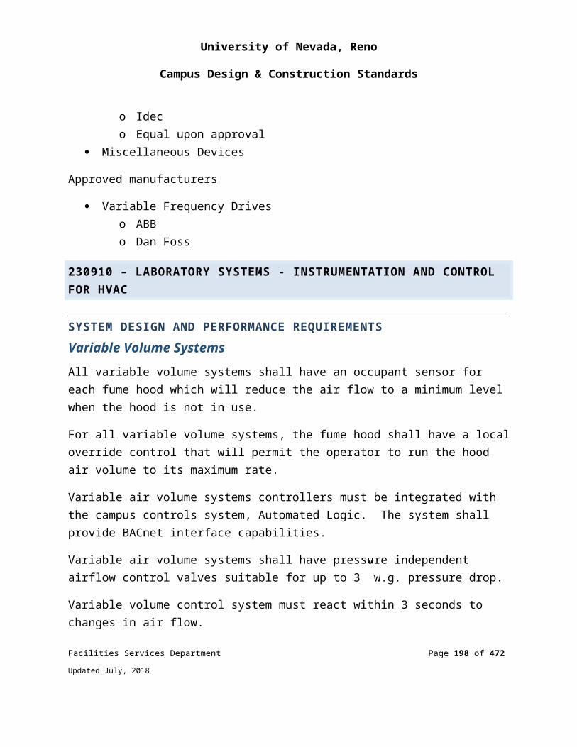
University of Nevada, Reno
Campus Design & Construction Standards
Acceptable generator manufacturers are: Detroit, Cummins and Caterpillar.
Tanks shall be double walled with a rupture basin.
The generator/engine/control panel shall be a package system by a specified manufacturer with a minimum of ten years documented experience.
Generator sets shall have “One source responsibility”. Gen sets and components to be prototype tested, factory built and production tested.
Generator sets below 750 kW shall meet or exceed Tier III emissions minimum.
Generator supplier shall have factory authorized engine and generator service center within fifty miles.
Generator set shall be rated for 6000’ altitude or higher.
Generator set controls shall have pre-alarms for fuel level, coolant level, coolant temp, oil pressure as well as safety shutdowns.
Generator shall be equipped with controls to permit remote communication.
Generator shall be equipped with PMG (permanent magnetic excitation).
Engine shall be equipped with an electronic governor.
Generator set shall be rated for 120º F. ambient temperature or higher.
Generator/ engine cooling system shall be capable of dissipating 100% engine heat rejection @ 100% rated load at spec. temp and altitude.
Generator set enclosure shall be weatherproof and sound attenuated for 75 dB or less at 21 feet.
Generator set enclosure shall be rodent proof.
Unit mounted or remote load bank @ 50% or greater of rated load.
Generator set shall be supplied with a catwalk if mounted above normal reach.
Generator set shall be equipped with external drains for coolant, oil and fuel.
The generator shall have 2/3 pitch windings.
Facilities Services Department Page 198 of 349
Updated July, 2018

University of Nevada, Reno
Campus Design & Construction Standards
Generator set shall have isolation valves for engine heater.
Engine cooling system shall be equipped with a coolant level sight glass.
Engine heater(s) shall have an adjustable thermostat(s).
Battery charger shall be equipped with adjustable rate.
Generator set shall be equipped with complete service and parts manuals.
Programming and or monitoring software and connecting cables to be included as well as detailed training.
Provide a non-draw out molded case circuit breaker at the generator for generator protection.
Generator shall be capable of 75% block load minimum.
Installation shall include minimum two-hour load bank testing on startup at 100% load rating.
Provide minimum two hours on-site operator training.
263600 - AUTOMATIC TRANSFER SWITCHES
SYSTEM DESIGN AND PERFORMANCE STANDARDSTransfer switches shall be rated to carry 100 percent of rated current continuously.
Transfer switches shall be closed transition 4 pole (switched neutral) switches.
All sensing controls such as under voltage, overvoltage, under frequency, engine start, return to normal etc. shall be adjustable.
Provide an exerciser clock to set the day/time/duration of the generator set exercise/test period.
Acceptable manufacturers are: Asco, Zenith, Detroit, Cummins and Caterpillar.
Transfer Switch shall include an in-phase monitor option.
Transfer Switch shall include transfer inhibit capabilities.
Facilities Services Department Page 199 of 349
Updated July, 2018
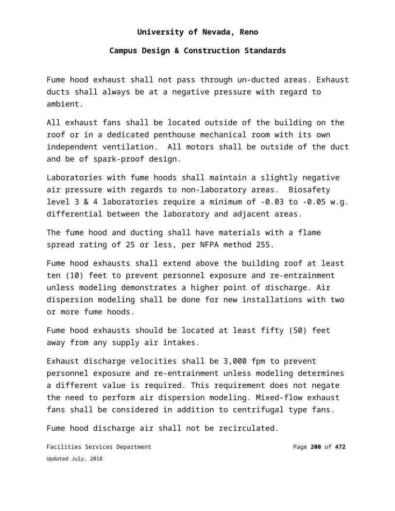
University of Nevada, Reno
Campus Design & Construction Standards
Transfer Switch shall include remote monitoring capabilities.
Start up, (configuring) by factory representative to be included.
Provide a separate dedicated transfer switch for code required emergency lighting.
265000 - LIGHTING
SYSTEM DESIGN AND PERFORMANCE STANDARDSSpecial use areas or areas used for multiple purposes which may require unusual levels of illumination should be reviewed with the University of Nevada, Reno Facilities Services Department and approved during the early stages of design.
LED lighting shall be considered for all indoor and outdoor installations.
For outdoor lighting use only lamps of 4000 degree Kelvin rating with the highest color rendering index available.
Lighting in all offices and classrooms shall be designed for a minimum maintained average lighting level of 40 foot-candles at the desktop surface.
Step lighting for individual steps shall not be installed. Provide lighting for steps using sidewall mounted fixtures and/or pole lighting for exterior steps.
All 4’ fluorescent fixture ballasts shall be Philips Advance ICN series, or equal.
All 4’ fluorescent lamps shall be Philips F32T8/ADV941/2XL/ALTO ll series, or equal.
The University shall not accept the use of “Visa Lighting Products”, “G.E. Lamps”, or “WPI Ballasts”.
All exterior doors and entries shall have illumination on the building exterior.
Fluorescent fixtures shall be provided with electronic ballasts having ballast factors of .87 or higher and harmonic distortion of 20% or less.
All exit signs shall have green letters with LED lamps and battery back-up.
All fluorescent lamps shall be T-8 4100K in new construction and match existing in retrofit construction. Only use T-5 lamps in high bay applications for storage or gymnasiums.
Facilities Services Department Page 200 of 349
Updated July, 2018

University of Nevada, Reno
Campus Design & Construction Standards
Control of lighting shall be provided for all spaces including small single offices. Lighting shall be controlled by occupancy sensors, multilevel switching or daylight diming in accordance with the International Energy Conservation Code (IECC).
Utilize occupancy sensors in all spaces except foyers, stairways and lobbies. This includes the use of motion sensors in corridors.
Only emergency lighting in stairways, electrical rooms and exit signs shall have battery backup. All other code required emergency lighting shall be provided back-up power by a separate dedicated emergency transfer switch unless the building is not equipped with a backup generator. Mechanical room lighting shall be connected to the emergency lighting system.
Provide an independent lighting control system for time of day, day of week, timed control of the lighting for that lighting which is not connected to motion sensors. Provide the ability to turn the lighting off at pre-selected times and provide a timed override switch in a convenient and logical place to override the time clock.
All lighting control systems shall be connected to the campus DDC system.
For large auditoriums, classrooms, gathering areas, etc. (determine the areas on a project by project basis) where day-lighting is available, provide a light harvesting control system. Where light harvesting is utilized the system shall utilize electronic dimming ballasts (not step level switching).
No proprietary luminaries shall be specified.
Lighting circuits shall not be 480 volt.
All fluorescent lay-in type fixtures shall be 2’ x 4’. 2’ x 2’ fluorescent fixtures not allowed.
ELECTRICAL COMMISSIONING
PAD MOUNT SWITCH Work includes visual inspections of the equipment, anchoring, paint, labeling, clearances, grounding, terminations, testing caps, bleeder wires, cable supports, conductor phasing, vault cleanliness, vault and door hardware.
Review of cable testing report for each conductor.
Facilities Services Department Page 201 of 349
Updated July, 2018
University of Nevada, Reno
Campus Design & Construction Standards
Review and record settings of overcurrent protection.
Test tripping mechanisms for each fault interrupter.
Verify and record gas levels.
Verify arc flash labeling is installed and in agreement with arc flash study.
PAD MOUNT TRANSFORMER Work includes visual inspections of the equipment, anchoring, paint, labeling, clearances, grounding, torqueing of terminations, conductor phasing, cleanliness, door hardware, and door seals.
Review cable testing report for each conductor.
Verify gauges are working properly and record gauge readings.
Verify arc flash labeling is installed and in agreement with arc flash study.
MAIN SWITCHBOARD Work includes visual inspections of the equipment, anchoring, paint, labeling, nameplate information, clearances, grounding, torqueing of terminations, conductor phasing, cleanliness, door hardware, and door seals.
Review cable testing report for each conductor.
Record all circuit breaker settings and verify that each setting is in accordance with the coordination study.
Verify arc flash labeling is installed and in agreement with arc flash study.
Test and verify the accuracy of the load meter in each function and verify values can be seen on the campus control system.
Test and verify the operation of the shunt trip mechanism.
Inspect installation and functions of the surge suppression device and verify SPD lead lengths are as short as possible.
DISTRIBUTION BOARDS
Facilities Services Department Page 202 of 349
Updated July, 2018
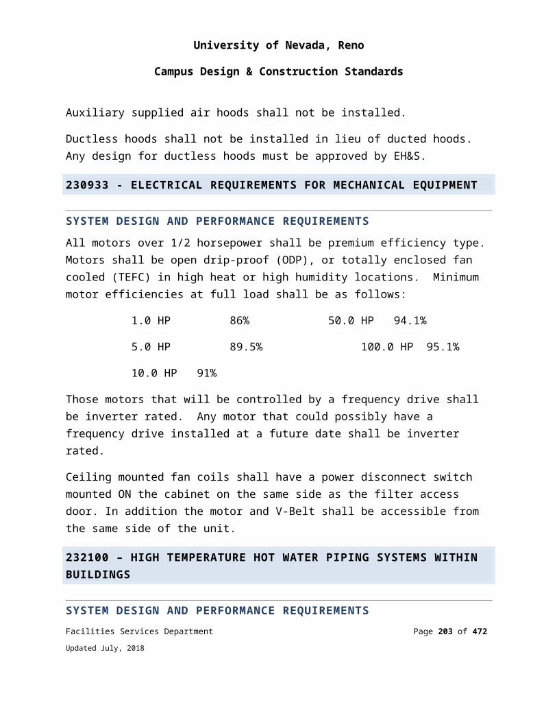
University of Nevada, Reno
Campus Design & Construction Standards
Work includes visual inspections of the equipment, anchoring, paint, labeling, nameplate information, clearances, grounding, torqueing of terminations, conductor phasing, cleanliness, door hardware, and door seals.
Review cable testing report for each conductor.
Record all circuit breaker settings and verify that each setting is in accordance with the coordination study.
Verify arc flash labeling is installed and in agreement with arc flash study.
Inspect installation and functions of the surge suppression device and verify SPD lead lengths are as short as possible.
STEP DOWN TRANSFORMERS Work includes visual inspections of the equipment, anchoring, paint, labeling, nameplate information, clearances, grounding, torqueing of terminations, conductor phasing, vibration isolation, and cleanliness.
Review cable testing report for each conductor.
Verify arc flash labeling is installed and in agreement with arc flash study.
BRANCH CIRCUIT PANELSWork includes visual inspections of the equipment, anchoring, paint, labeling, nameplate information, clearances, grounding, torqueing of terminations, conductor phasing, cleanliness, and door hardware.
Review cable testing report for each feeder conductor.
Record main circuit breaker settings and verify that each setting is in accordance with the coordination study.
Verify arc flash labeling is installed and in agreement with arc flash study.
LIGHTING CONTROL/TIME CLOCKS/PHOTOCELLS Work includes a visual inspection of the equipment, anchoring, paint, labeling, nameplate information, clearances, grounding, terminations and cleanliness.
Facilities Services Department Page 203 of 349
Updated July, 2018
University of Nevada, Reno
Campus Design & Construction Standards
Test each device for on/off operation by local and remote control by DDC system.
Verify and record timed on/off settings.
Test all motion sensors and dual level switching in each room.
Test on/off function of all exterior lighting and verify time settings.
Verify each lighting fixture is working properly.
Perform a 90-minute run test of all emergency lighting with the building power off.
Verify all emergency lighting fixtures both interior and exterior are providing required lighting levels at 90 minutes.
GENERATOR Work includes visual inspection of the equipment, anchoring, paint, labeling, nameplate information, clearances, grounding, termination, no leaks, gauges, battery charger, battery heater, block heater, meters, control panel, weatherproof/sound attenuated enclosure, bird screens, and cleanliness.
With permanently installed or portable load bank perform and record a full load 3 hour run test.
Test and record the function of the following items: gauges, battery charger, battery heater, block heater, emergency stop switch, meter, control panel functions, fuel level alarm, oil pressure alarm, coolant level alarm, high temperature alarm.
With the generator running record sound levels in multiple directions and at multiple distances.
Verify arc flash labeling is installed and in agreement with arc flash study.
Test and verify that the function of the shunt trip device.
Verify fuel tank is full after all tests.
AUTOMATIC TRANSFER SWITCH Test and record all functions are operational.
Perform a loss of power test to the building and verify all functions work properly.
Facilities Services Department Page 204 of 349
Updated July, 2018
University of Nevada, Reno
Campus Design & Construction Standards
Test and verify all by-pass functions.
Verify and record frequency and duration of generator exercising.
Verify arc flash labeling is installed and in agreement with arc flash study.
UPS SYSTEMWork includes visual inspection of the equipment, anchoring, paint, labeling, nameplate information, clearances, grounding, terminations, control panel, batteries, wiring, and cleanliness.
With batteries fully charged perform a full load run test.
Record voltage and current levels every minute during the test for the duration of the specified run time.
Verify closed transition switching during a loss of power and restoration of power to the building.
Test and verify all alarms.
Test and verify by-pass functions.
Verify arc flash labeling is installed and in agreement with arc flash study.
FIRE ALARM SYSTEM Work includes visual inspection of the equipment, anchoring, paint, nameplate information, batteries, wiring, grounding, terminations, device installations and locations. Test all functions of the system.
Verify the function and address of each initiating and indicating device for supervisory, trouble and alarm signals.
Test and verify interface with HVAC equipment and controls.
Perform a loss of power test.
Verify required certifications and proper tagging.
Perform all tests in the presence of the Authority Having Jurisdiction.
Facilities Services Department Page 205 of 349
Updated July, 2018
University of Nevada, Reno
Campus Design & Construction Standards
Test the auto-dialer for functionality.
Verify all supervisory, trouble and alarm signals are cleared upon completion.
End of Division 26
ELECTRICAL
Facilities Services Department Page 206 of 349
Updated July, 2018
University of Nevada, Reno
Campus Design & Construction Standards
DIVISION 27: COMMUNICATION
27000 – GENERAL
UNIVERSITY OF NEVADA, RENO COMMUNICATIONS / IT BUILDING REQUIREMENTSWhen a department or building is involved in planning a network, renovating an existing network, building a new building, or renovating an existing space, University of Nevada, Reno Network Operations (NetOps), must be contacted before the start of the project. The NetOps will assist facilities or the architect in defining the specific details of each project. NetOps will also assist in ensuring that all appropriate network costs are included in project budgets.
Typically, a 2-3-day notice sent via email to: [email protected] will be sufficient to schedule the inspections. If the cabling portion of the project is small in nature, some or all the inspections may be performed at the same time.
Director of Unified Communications & Network Operations (UCNO) or his designee, must approve in advance all computer network designs and installations.The contract drawings and specifications shall cover all work enumerated under the respective headings. The contract drawings are diagrammatic only, as far as final location is concerned. Any item of work not clearly included, specified or shown, and any errors or conflict between contract drawings, specifications, codes and field conditions shall be clarified by a written request to the engineer before bidding.
SCHEDULES FOR COMMUNICATIONS INSTALLATION INSPECTIONSDuring construction, the cabling contractor must contact UNR NetOps to inspect the work at the following milestones:
1. At pre-construction meeting.
2. While pulling horizontal cable from Telecommunication Room (TR).
3. During termination of the horizontal cabling in the TR on the patch panels.
4. During wall outlet terminations.
5. When testing and labeling faceplates.
Facilities Services Department Page 207 of 349
Updated July, 2018
University of Nevada, Reno
Campus Design & Construction Standards
Unacceptable Room LocationsAny areas subject to water or steam infiltration, particularly basements. A floor drain is required if there is any risk of water entering the ER. Any areas exposed to excessive heat or direct sunlight. Any areas exposed to corrosive atmospheric or environmental conditions. Near or adjacent to any potential sources of electromagnetic interference (EMI) or radio frequency interference (RFI) such as large electric motors, power transformers, arc welding equipment, or high power radio transmitting antenna.
FirestoppingAll firestopping must be in accordance with NEC 300-21, NFPA 101, ASTM E814, and ASTM E119.
TELECOMMUNICATIONS INFRASTRUCTUREThe contract drawings and specifications are intended to cover all work enumerated under the respective headings. The contract drawings are diagrammatic only, as far as final location is concerned. Any item of work not clearly included, specified or shown, and any errors or conflict between contract drawings, specifications, codes and field conditions shall be clarified by a written Request for Information (RFI) to the engineer before bidding.Contractor shall be certified by the manufacturer for installation of the proposed system products and provide a minimum 20-year manufacturer warranty at completion of project. The approved system products for UNR are; CommScope/SYSTIMAX and Belden/CDT for copper cabling and Corning Cable Systems for fiber infrastructure. Installation contractor shall deliver these certification documents with project submittals. Note: New construction projects and buildings that are currently CommScope/SYSTIMAX, shall use CommScope/SYSTIMAX infrastructure system. Buildings where current cable plant is Belden shall match existing cabling. (renovations/adds/ moves and changes) All infrastructure cabling systems must be a single manufacturer (Original Equipment Manufacturer), including patch panels, patch cords, cabling, jacks, faceplates.
All infrastructure cabling systems must be a single manufacturer (Original Equipment Manufacturer), including cabling, patch panels, patch cords, jacks, faceplates.Contractor shall be certified by the manufacturer for installation of the proposed system products. The approved manufacturers of communications infrastructure systems for UNR are; CommScope/SYSTIMAX and Belden/CDT for copper cabling and Corning Cable Systems for
Facilities Services Department Page 208 of 349
Updated July, 2018
University of Nevada, Reno
Campus Design & Construction Standards
fiber infrastructure. All new constructions shall be Category 6A infrastructure systems only. Note: Cable in existing buildings shall match current system vendor.
27100- INTERIOR COMMUNICATION PATHWAYS
COMMON WORK RESULTS FOR COMMUNICATIONSWork Area Outlets (WAO) WAO density:
A minimum of two WAO locations shall be installed per work area. For planning purposes, space allocated per work area averages 100-square feet.
For building areas where It is difficult to add additional WAO’s at a later date (i.e. private office space), a minimum of two separate WAO locations shall be provided in the initial design for that area, and they shall be located to offer maximum flexibility for change within the work area, (i.e. on opposing walls in private office space).
A minimum of one WAO shall be installed with two data cables at the Fire Alarm Control Panel (FACP) located in the electrical or mechanical room.
A minimum of one WAO shall be installed with data cable for each elevator phone at the Elevator Control Panel.
A minimum of one WAO shall be installed with one data cable at the Building Environmental Control Panel.
A minimum of one WAO shall be installed with one data cable at the Security NVR/DVR location.
WAO locations shall be coordinated with the furniture layout. A power receptacle should be installed near each WAO location (i.e. within 3-feet). WAO locations are typically at the same height as the power receptacles.
Open office area interior design, telecommunications distribution planning, and power system distribution planning should be coordinated to avoid conflicting assignments for pathways or WAO locations, installation sequencing problems, and other difficulties.
BUILDING INTERFACES Furniture pathways are entered from building walls, columns, ceilings, or floors. The interface between the building and furniture requires careful planning and may require special products or furniture options. Safety, reliability, and aesthetic concerns all favor concealment of the building and furniture pathway interface. These pathway interfaces shall not trap access covers or otherwise block access to WAO’s, building junction
Facilities Services Department Page 209 of 349
Updated July, 2018
University of Nevada, Reno
Campus Design & Construction Standards
boxes or pathways. Pathways used to interconnect the furniture with building horizontal pathways shall be provided with a cross-sectional area at least equal to the horizontal pathways cross-sectional area for the floor area being served.
Walls and Columns Raceways shall be provided between furniture pathways and the inside of building walls or columns. Floors A raceway shall be provided between furniture pathways and horizontal floor pathway terminations. Alignment of furniture with building modules, duct locations and other cable delivery means shall be considered as part of the layout planning.
Campus Environments Construction involving a new or existing building structure shall have an assessment of the outside conduit infrastructure, (i.e. connections between buildings) accomplished very early in the project cycle. This assessment is of importance if demolition of any structure is required as part of the overall project, and/or the new project may impact an existing conduit infrastructure.
Abandoned CablingAs part of the construction process, handling of abandoned cabling shall meet NEC guidelines.
Cable Tray for Communications SystemsThe use of a wire basket tray or cable runway systems are the preferred methods of cable pathways within the corridors. A minimum of 12-inches of clearance shall be provided above the cable tray and a minimum clearance of 12 to 18-inches on at least one side shall be provided for access to tray. Please refrain from specifying Two Side Rail (Metallic) Cable Tray Systems due to the limited amount of space in the ceiling areas. Minimum size is 12” wide x 4” high. Specify larger size to maintain 50% fill ratio.Chatsworth Products, Basket Tray or Runway systems or equal
Conduits and Back Boxes for Communications SystemsEach habitable space must be connected individually to the cable tray with two locations, at least one 1” conduit for Cat 6 projects and 1 ¼” for Cat 6A projects. In labs, or other multi-drop locations, each RJ-45 computer drop will have its own 1” or 1 ¼" conduit. Spare conduits shall be plugged with expandable plugs. No flexible conduit Facilities Services Department Page 210 of 349
Updated July, 2018
University of Nevada, Reno
Campus Design & Construction Standards
shall be used unless specifically approved by the Engineer. All conduit work must comply with current edition of National Electrical Code (NEC)
Surface Raceways for Communications SystemsAcceptable material shall be Wiremold (TM) 700 series or applicable 2000, 3000, or 4000 series depending on manufacturers recommended fill ratios. Raceway to be securely mounted to walls with screws anchored into walls. Screws to be drilled into base of raceway 12 inches apart on center.
Junction BoxesNo conduit run shall be more than 100 feet between access points. No conduit shall contain more than 180-degree of bends between junction boxes. Junction boxes shall be no less than 18”x18”x12”.
Cable RoutingAll cable and MaxCell (TM) routings shall utilize the path of least obstructions and shall be run parallel or perpendicular to existing walls. Hang multiple horizontal conduits in tight, vertically organized arrays and run vertical riser cabling similarly. Avoid creating obstructions to future mechanical/electrical work.
EMI (Electromagnetic interference)All routing of copper cabling shall meet the minimum distances according to TIA standards. Whenever possible, avoid running UTP in locations where temperature will be below 40 degrees Fahrenheit or above 115 degrees Fahrenheit. Humidity should normally be in the range of 8-80%. All cable, conduit, and Wiremold (TM) routings shall utilize the path of least obstructions and shall be run parallel or perpendicular to existing walls. Hang multiple horizontal conduits in tight, vertically organized arrays and run vertical riser similarly. Avoid creating obstructions to future mechanical/electrical work. All interior conduits required under this contract shall be provided with a non-conductive, fish tape, or approved nylon pull string.
CONCEALMENTHorizontal and backbone raceway and cabling shall be concealed above ceilings, in walls, below slabs, and elsewhere throughout building. If concealment is impossible or impractical, or in areas without ceilings, the Owner’s Representative shall be notified of the proposed routing prior to starting that portion of the work.
Facilities Services Department Page 211 of 349
Updated July, 2018
University of Nevada, Reno
Campus Design & Construction Standards
WATERPROOFINGThe Contractor shall seal all foundation penetrating conduits and all service entrance conduits and sleeves to eliminate the intrusion of moisture, gases and rodents into the building. This requirement also applies to spare conduits.
27200- TESTING, LABELING AND ADMINISTRATION
TESTINGInside Plant (ISP) CopperContractor must supply to UNR NetOps and the engineer a complete set of test records 2 weeks prior to equipment installation. Testing is to be performed using a Fluke DSX or equivalent tester. Testing shall be per IEEE Standards and EIA/TIA TSB-67.
Outside Plant (OSP) CopperAll OSP cable pairs in each of the copper feeders must be tested for continuity, polarity and shorts. The contractor must correct cables that do not pass.
OSP/ISP FiberAll fiber shall be tier 1 and tier 2 tested using a Fluke DSX or equivalent tester.
LABELING Every component of the technology wiring system must be labeled. All cables must be labeled to show the source and destination. All labels must be easily viewed. All cables, components and device identifiers must be unique. All labels must be permanent and machine printed.
RacksRacks Shall be installed and numbered in the TR from left to right (viewed from front) first rack on left labeled 1 then sequentially across the room to right.
Patch PanelAll patch panels must be labeled starting with A, B, C, etc. from top to bottom and left to right. All patch panel ports must be labeled with the room number so as not to obscure the patch panel port numbering. Use the existing 1-48 numbering from the patch panel. All cabling shall be bundled geographically and punched down with other cables from
Facilities Services Department Page 212 of 349
Updated July, 2018

University of Nevada, Reno
Campus Design & Construction Standards
that area in a sequential manor, I.E. all cables from room 100 would directly precede all cables from room 101 on the patch panel.Any port supporting an access point (AP) shall be labeled “AP Room number”.Example: If an AP is in room 204, the label on them patch panel will be “AP204”.
Work Station FaceplateEach communications faceplate will be labeled with the IDF number and Rack designation plus patch panel in rack labeled alphabetically in descending order. A on top through H, and patch panel port number 1-48, On a 48-port patch panel. All faceplate labels must be machine generated thermal type label. All faceplate labels to be put under plastic cover provided on faceplate for that purpose. No faceplate shall be used that does not provide a label area with a clear plastic cover.Top 1A1, 1A2, 1A3, etc.Bottom (IDF room Number) – 1A4, 1A5, 1A6 Where A designates the first patch panel in rack and 1-48 are the number of ports
on that panel
Unshielded Twisted Pair (UTP) CableAll UTP cabling must be labeled within 5 inches of the attached connector and within 6 inches of the attached connector at the distribution location. Label must indicate the room designation and the faceplate circuit of the cable. For example, label: 102-1A1 indicates that the cable serves room 102, to rack number 1 and patch panel A port 1.
Fiber CablePlace a label on the bulkheads of the fiber enclosure and the end of the fiber cable. Label the far side with building and room of near side destination. Near side label with building and room number of where the fiber was routed from.
Patching Contractor shall patch in every cable installed from the patch panel into the network
switches using ONLY 7’ patch cords AFTER TESTING IS COMPLETE.
Patch cables will be plugged in from the patch panel to the switch port shown below:
Patch panel port 1 2 3 4 5 6 7 8 9 10 11 12
Facilities Services Department Page 213 of 349
Updated July, 2018
University of Nevada, Reno
Campus Design & Construction Standards
Switch port 23 21 19 17 15 13 11 9 7 5 3 1
Patch panel port 13 14 15 16 17 18 19 20 21 22 23 24Switch port 47 45 43 41 39 37 35 33 31 29 27 25
Patch panel port 25 26 27 28 29 30 31 32 33 34 35 36Switch port 24 22 20 18 16 14 12 10 8 6 4 2
Patch panel port 37 38 39 40 41 42 43 44 45 46 47 48Switch port 48 46 44 42 40 38 36 34 32 30 28 26
Cable in patch panel ports 1-12 and 25-36 are to be routed through the left vertical cable management, and cords in ports 13-24 and 37-48 are to be routed through the right vertical management.
Patch cords are to be bundled together with Velcro in groups of 12 matching the chart in section B.
All patch cords are to be connected to the switches in the corresponding rack. At no point should patch cords cross from one rack to another.
o If at any point the network switches in a rack have reached max capacity an E-mail is to be sent to [email protected]
o 15’ patch cords are to be handed off to a NetOps employee. o A CSV or Excel document is to be provided populated with the following
columns: IDF room number, rack number, patch panel letter, patch panel port, patch panel label, switch number, and switch port.
CLEANINGAt the completion of work each day, the contractor shall clean all work areas of debris, trash, dust, etc. All ceiling tiles shall be reinstalled and materials placed in the designated storage area(s). All areas shall be restored to a normal condition, as found. At the completion of the work required under this contract and just before acceptance by the Owner, thoroughly clean all exposed equipment and accessories.
ADMINISTRATION Pre-Construction SubmittalsContractor is to submit to the engineer a complete documentation package before commencement of the project. Contractor shall not commence work before approval of
Facilities Services Department Page 214 of 349
Updated July, 2018
University of Nevada, Reno
Campus Design & Construction Standards
submittals, any additional costs to conform to approve submittals shall be borne by the contractor. The package shall include:
Shop Drawings – must show all WSO locations with cable ID’s, general cable routing, and firewall penetrations
o Shop drawings of all telecommunications room plan view layouts, rack elevations and equipment
Product data – a complete list of all materials used in the cable system, including manufacturer and part number
o Cut sheets of all proposed components Certifications – provide as detailed in the manufacturer and technician certifications
section At least one BICSI Certified Installer
PROJECT CLOSEOUT DOCUMENTSRecord DrawingsContractor is to provide to the owner a complete network documentation package upon completion of the project. The package shall include:
As built drawings – must show all WSO locations with cable ID’s, general cable routing, and firewall penetrations. Delivered as PDF emailed to [email protected] .
Test Reports – delivered on by E-mail Test documentation for UTP cabling Test documentation for fiber optic cabling Test documentation for multi-pair copper cabling
WarrantyProvide 20-year manufacturer’s warranty listing UNR as the owner along with the specific building name where work was performed.
27300 – TELECOMMUNICATION ROOMS
Refer to ANSI-TIA-569-D pathways and spaces for Communications Cabinets, Racks, Frames and Enclosures
TELECOMMUNICATIONS SPACES MINIMUM REQUIREMENTS:
Facilities Services Department Page 215 of 349
Updated July, 2018

University of Nevada, Reno
Campus Design & Construction Standards
Telecommunications rooms shall have only one lockable entrance door, 36 inches wide and 80 inches in height, without windows, that opens towards the outside of the room, and does not open into another room. There shall be a minimum of three walls covered by ¾ in. fire rated plywood painted with two coats of white fire-retardant paint and rated label shall be clearly visible. Telecommunications rooms shall not be shared with other building services. Electrical distribution panels/transformers pose the threat of damage or EMI interference, heat or clearance problems. Storage areas present fire hazards as well as hindering access to equipment. These rooms shall be reserved for Data and Voice communications infrastructure and equipment only. No fire alarm, security, DVR’s, or other electronic equipment not specifically required by network and voice infrastructure. Floors shall be concrete. Carpeted floors are not acceptable due to static discharge. Drop ceilings shall not be installed in telecommunications rooms and sheetrock shall be finish to below upper deck.
BUILDING DISTRIBUTION FACILITY (BDF) / INTERMEDIATE DISTRIBUTION FACILITY (IDF) The building distribution facility (BDF) for New Construction shall be 10 x 15 foot minimum.Design and placement of IDF, must be based on keeping cable runs to work areas under 295 ft. Preferably stacking these rooms on each floor, if possible. Horizontal and vertical riser conduits or cable trays must be available from each IDF to the BDF. Each IDF shall have a minimum of 2 – #4 trade size conduits for cable access to horizontal cable path and vertical riser pathways.
Freestanding Equipment Rack Freestanding equipment racks shall be Chatsworth Products Incorporated (CPI) or
equal, 7 ft. X 19 in. floor mount two-post rack, black in color. Mfg. Part #55053-703 Equipment racks must be properly anchored to the concrete structure using ½” X 3
¾” wedge anchors to support the rack and Its equipment. Each equipment rack shall be properly bonded and grounded using a #6 ground wire
and extended to the bus bar within the room. (Bus bar provided and installed by EC) Equipment racks shall be outfitted with cable runway elevation kits for connection to
overhead cable runway. Mfg. Part #10506-706 Maximum 8, 48 port patch panels per rack
Facilities Services Department Page 216 of 349
Updated July, 2018
University of Nevada, Reno
Campus Design & Construction Standards
Wire Management Vertical wire management shall be supplied to support each freestanding rack within
the telecom rooms. Between each rack, provide one CPI Evolution vertical cable manager, double-
sided, 15 in. wide X 7 ft. high, black in color. Mfg. Part #35525-703 At each end of the row of racks, provide one CPI Evolution vertical cable manager,
double-sided, 12 in. wide X 7 ft. high, black in color. Mfg. Part #35524-703 Each rack shall receive one CPI Evolution single-sided horizontal wire manager, 19”
W x 3 RMU x 8.2” D. Wire manager shall be placed in the middle of each rack to create a beltline across the row of racks (see attached rack elevation drawings). Mfg. Part #35441-703
Each rack shall receive one CPI cable management jumper & transition upper tray, 19” W x 2.22”H x 3.5” D, black in color. Mfg. Part #12183-719
Ladder Rack Ladder rack shall be installed to wrap the entire telecom room and over the top of
the equipment rack row. Provide CPI 18” cable runway for Category 6 installations. Mfg. Part #10250-718 Provide CPI 24” cable runway for Category 6A installations. Mfg. Part #10250-724 Ladder rack shall be supported with appropriate CPI hardware to include:
o Wall angle support kits – #11421-718 / #11421-724o Triangular support bracket - #11746-718 / #11746-724o Junction splice kit - #11302-701o Butt splice kit - #11301-701o Cable runway elevation kits - #10506-706
POWERThe room shall have one dedicated 20-amp circuit with 20-amp Quad outlets installed every 6 feet at 18 inches above finished floor per wall. Two dedicated 20-amp circuit with Quad outlets shall be located on the top of each 7-foot equipment rack (on top and behind each rack).
GROUNDING AND BONDINGAll grounding and bonding shall comply with ANSI J/STD-607-C.
27400 – COMMUNICATIONS BACKBONE CABLING
Ref: TIA 568C
Facilities Services Department Page 217 of 349
Updated July, 2018
University of Nevada, Reno
Campus Design & Construction Standards
OSP Copper Backbone Cable type Protector type and size
ISP COPPER BACKBONEEach IDF shall receive one (1) 25 pair plenum/riser (as appropriate) cable. Contractor shall terminate one (1) pair per port (on blue/white IDC’s) and coil the 25 th pair at the sheath opening with enough length to be utilized anywhere on the patch panel. Multi pair cable
Riser – Mfg. Part #18-499-33
Plenum – Mfg. Part #18-499-36
Category 5E Patch Panel
SYSTIMAX - Part #1100PSCAT5E-24
Belden - Part #AX103258
COMMUNICATIONS OPTICAL FIBER BACKBONE CABLING
OSP FIBER BACKBONEAll fiber optic cabling and termination apparatus shall be manufactured by Corning Cable Systems.Provide conduit duct banks with four 4” conduits to 2 different communications vaults leading to existing campus conduit infrastructure. Duct banks shall have no more than two 90-degree long sweep bends between access points. Each duct bank will have a green jacketed conducting locator wire that will be secured at each access point or vault. Each conduit will include the installation of 1800 pound mule tape with marked with footage. Conduit pathways to existing campus vaults will be designed in consultation with NetOps to verify available capacity in existing campus conduits.Provide (2) 72 strand Single Mode fiber optic cables originating from two different well-connected buildings to the BDF in consultation with NetOps. Each 72 strand fiber optic cable will be placed in a separate 4” conduit following two diverse paths from the adjacent buildings to the BDF. All conduits housing fiber optic cables shall receive (3) 3” 3 cell fabric innerducts to allow for future placement of cables. Terminate fiber optic cables using 12 LC Single Mode splice cassettes and place in 4 RU fiber optic
Facilities Services Department Page 218 of 349
Updated July, 2018
University of Nevada, Reno
Campus Design & Construction Standards
termination housings. OSP fiber optic cables shall NOT share a Fiber Optic Connector Housing with ISP cables.
Single Mode OSP Fiber OSP fiber optic cables shall be Corning Cable Systems 72 fiber, Single Mode (OS2)
Altos Loose Tube, Gel-Free, All Dielectric Cable with FastAccess Technology (Inter-Building Links) Mfg. Part #072EU4-T4701D20
Fiber optic cables shall follow diverse paths from the MDF to the BDF. Contractor shall provide a service loop of at least 75’ at each end of the cable on
fiber storage ring. Fiber optic cabling shall have no bends with a radius smaller than twenty times the
outside diameter of the enclosing sheath. Fiber optic cable will be labeled with both termination locations at each
communication vault or access point.
MaxCell (TM) Fabric Innerduct Fabric innerduct shall be MaxCell (TM) 3” 3 cell fabrics, detectable with an 18-gauge
solid copper core tracer wire. Standard thread color running along the length of the MaxCell (TM) “pack” shall be Black with each individual cell having its own unique thread stripe for easy identification. Mfg. Part #MXD3456BK-XXX (XXX identifies the length of the reel)
Contractor must secure MaxCell (TM) at each manhole so that it cannot be pulled back into the conduit during installation or placement of cables.
Contractor shall utilize an 1800lb swivel with an outside diameter of .875” to eliminate the possibility of twisting during installation. Any MaxCell (TM) that is found to have twists shall be removed and replaced at the expense of the Contractor. Mfg. Part #MXCIK11
Provide 4” duct plugs with nine (9) holes consisting of three (3) -1.10”, three (3) – 0.90”, three (3) – 0.70” holes. Duct plugs shall be placed whenever entering an IDF/BDF/MDF. Mfg. Part #MXCTP4
Fiber Optic Connector Housings Fiber optic connector housings shall be Corning closet connector housings, four rack
spaces, holding up to 12 CCH connector panels. Mfg. Part #CCH-04U All connector housings MUST be CCH-04U. Connector housings of lesser size or
density are NOT allowed regardless of the number of fiber terminations they are required to support.
Facilities Services Department Page 219 of 349
Updated July, 2018
University of Nevada, Reno
Campus Design & Construction Standards
Connector Panels Fiber optic connector panels shall be Corning 12F, LC UPC duplex, Single Mode
(OS2), single fiber (250um) Pigtailed Splice Cassettes. Mfg. Part # CCH-CS12-A9-P00RE
Pigtailed splice cassettes of greater density than 12 fibers are NOT allowed. Termination of all fiber optic cables MUST be performed via fusion splicer. Field
terminated fiber optic connectors are NOT acceptable
Fiber Optic Cable Storage Ring Provide a fiber optic cable storage ring no less than 24” in size to maintain the
proper bend radius and prevent any kinking of the fiber optic cable. The storage ring shall be able to hold up to 50’ of service coiled fiber. Fiber optic storage ring shall be Black Box Part #FOSR24 or equal
Place the fiber optic storage ring above of the underground conduits and secured to the plywood backboard so that the fiber service loop will not interfere with future cable installations.
Each fiber optic cable will be stored on its own storage ring at location of termination.
ISP FIBER BACKBONEProvide 24 strand single mode fiber optic cable from the BDF to each IDF. Each end of the fiber optic cable shall be terminated via fusion splicer using 12 LC pigtailed splice cassettes. Splice cassettes shall be housed in four rack space fiber optic connector housings. ISP fiber optic cables shall NOT share a Fiber Optic Connector Housing with OSP cables.
ISP Single Mode Fiber Optic Cable Single Mode fiber optic cable shall be Corning 24 F, Single mode (OS2), MIC Tight-
Buffered, Plenum, Interlocking Armored Cable. Mfg. Part #024E88-33131-A3 Contractor shall provide a service loop of at least 20’ at each end of the cable.
Fiber Optic Connector Housings Fiber optic connector housings shall be Corning closet connector housings, four rack
spaces, holding up to 12 CCH connector panels. Mfg. Part #CCH-04U All connector housings MUST be CCH-04U. Connector housings of lesser size or
density are NOT allowed regardless of the number of fiber terminations they are required to support.
Facilities Services Department Page 220 of 349
Updated July, 2018
University of Nevada, Reno
Campus Design & Construction Standards
Connector Panels Single Mode fiber optic connector panels shall be Corning 12F, LC UPC duplex,
Single Mode (OS2), single fiber (250um) Pigtailed Splice Cassettes. Mfg. Part # CCH-CS12-A9-P00RE
Pigtailed splice cassettes of greater density than 12 fibers are NOT allowed. Termination of all fiber optic cables MUST be performed via fusion splicer. Field
terminated fiber optic connectors are NOT acceptable.
Fiber Optic Cable Storage Ring Provide a fiber optic cable storage ring no less than 24” in size to maintain the
proper bend radius and prevent any kinking of the fiber optic cable. The storage ring shall be able to hold up to 50’ of service coiled fiber. Fiber optic storage ring shall be Black Box Part #FOSR24 or equal
Place the fiber optic storage ring below or above the conduits where the cable enters the closet and secure to the plywood backboard. Service loop shall be placed where it will not interfere with future cable installations.
Each Fiber optic cable will be stored on its own storage ring at location of termination.
27500 – COMMUNICATIONS HORIZONTAL CABLING
All new construction projects shall follow Category 6A specifications and standards.All existing or retrofit projects shall follow Minimum Category 6 to match building existing cable plant in Category and Cable manufacturer and specifications.Provide a complete (depending on project type) structured cabling solution to match building existing cable plant in Category and Cable manufacturer. Cabling systems shall be from a single manufacturer per the following specifications. All horizontal cabling shall be Plenum rated.
COPPER CABLE Horizontal copper cable shall be 4-pair, unshielded twisted pair, Plenum,
o SYSTIMAX – Mfg. Part #2091B BL (6A)
o SYSTIMAX – Mfg. Part #2071 (6)
o Belden – Mfg. Part #10GX13 (6A)
o Belden – Mfg. Part #3600 (6)
Horizontal cable runs shall not exceed 295ft in length. Each workstation outlet shall receive (2) cables.
Facilities Services Department Page 221 of 349
Updated July, 2018
University of Nevada, Reno
Campus Design & Construction Standards
Each wireless access point (WAP) location shall receive (1) cable drop.Copper Patch PanelsPart numbers:
SYSTIMAX – Mfg. Part #360-IPR-1100-E-GS6-2U-48 (6A)SYSTIMAX – Mfg. Part #360-IPR-1100-E-GS3-2U-48 (6)Belden – Mfg. Part # AX103256 (6A)Belden – Mfg. Part #AX103255 (6)
All horizontal copper cables shall terminate on patch panels following T-568B termination configuration.
Work Station OutletsPart numbers:
SYSTIMAX – Mfg. Part #MGS600-262 (6A)SYSTIMAX – Mfg. Part #MGS400-262 (6)Belden – Mfg. Part # AX102282 (6A)Belden – Mfg. Part # AX101320 (6)
FaceplatesPart numbers:
SYSTIMAX – Mfg. Part # M14L-262Belden – Mfg. Part #AX102249
Blank inserts shall be used to fill any unused ports on faceplate. Color shall match faceplate.
Surface Mount Boxes (SMB’s)Part numbers:
SYSTIMAX – Mfg. Part # M102SMB-B-262Belden – Mfg. Part # AX102652
Copper Patch CordsPart numbers:
SYSTIMAX – Mfg. Part # CPCSSX2-0ZF007 (6A, 7’)SYSTIMAX – Mfg. Part # CPCSSX2-0ZF015 (6A, 15’)SYSTIMAX – Mfg. Part # CPCSSX2-0ZF025 (6A, 25’)SYSTIMAX – Mfg. Part # CPC3312-0ZF007 (6, 7’)SYSTIMAX – Mfg. Part # CPC3312-0ZF015 (6, 15’)SYSTIMAX – Mfg. Part # CPC3312-0ZF025 (6, 25’)Belden – Mfg. Part #CA21106007 (6A, 7’)Belden – Mfg. Part #CA21106015 (6A, 15’)
Facilities Services Department Page 222 of 349
Updated July, 2018
University of Nevada, Reno
Campus Design & Construction Standards
Belden – Mfg. Part #CA21106025 (6A, 25’)Belden – Mfg. Part #C601106007 (6, 7’)Belden – Mfg. Part #C601106015 (6, 15’)Belden – Mfg. Part #C601106025 (6, 25’)
Copper patch cords shall be provided in lengths of 7ft at IDF, 15ft at WAO, or 25ft at WAP location.All patch cords shall match the manufacturer of the system installed.
27600- WIRELESS NETWORKING
An appropriate wireless design shall be provided in the plans and virtualization of coverage shall be submitted to [email protected].
All designs shall provide coverage to all parts of the building at a signal strength of -65dBm or greater on the 5GHz spectrum.
All Wireless Access Points shall receive 1 Category 6A/6 cable. The copper cables will be permanently attached in interstitial space (above ceiling)
on a two port SMB (biscuit).o At no time should a support be attached to building infrastructure designed for
other purposes, i.e. drop tile wire support, conduits, plenum, electrical conduits/ boxes.
Contractor shall leave a 25ft CMP patch cord in the ceiling where the WAP cables terminate.
All WAP’s shall be installed and secured with an appropriate bracket, including WAPs that are installed in interstitial space (above ceiling).
For outdoor WAPs, cable from the patch panel will be terminated to interior SMB near penetration point. An outdoor patch cord will be pulled from the interior SMB (biscuit) to the outdoor WAP.
The penetration point through which the outdoor rated patch cord passes shall weather sealed.
Facilities Services Department Page 223 of 349
Updated July, 2018

University of Nevada, Reno
Campus Design & Construction Standards
Facilities Services Department Page 224 of 349
Updated July, 2018

University of Nevada, Reno
Campus Design & Construction Standards
IDF – Example Layout
Facilities Services Department Page 225 of 349
Updated July, 2018
University of Nevada, Reno
Campus Design & Construction Standards
Facilities Services Department Page 226 of 349
Updated July, 2018
University of Nevada, Reno
Campus Design & Construction Standards
27700 - CODES AND STANDARDS
The minimum standards for all electrical work shall be the 2011 revision of the NEC and the current revision(s) of TIA 568, 569, and 570. Whenever and wherever OSHA and/or federal, state, and/or local laws or regulations and/or design require higher standards than the NEC, then these laws and/or regulations and/or design shall be followed.All work shall meet all applicable codes and standards, including but not limited to:
National Fire Protective Assoc. (NFPA) 70Building Industry Consulting Service International (BICSI) Standards National Electrical Manufacturers Assoc. (NEMA) Standards Electronics Industry Assoc./Telecom. Industry Assoc. (EIA/TIA) 568C University of Nevada System requirementsANSI/TIA-568-C.0 – Generic Telecommunications Cabling for Customer Premises.ANSI/TIA-568-C.1 – Commercial Building Telecommunications Cabling Standard.ANSI/TIA-568-C.2 – Balanced Twisted-Pair Telecommunication Cabling and Components Standard.ANSI/TIA-568-C.3 – Optical Fiber Cabling Components Standard.ANSI/TIA-569-D – Commercial Building Standard for Telecommunications Pathways and Spaces.ANSI/TIA-570-B – Residential Telecommunications Infrastructure Standard.ANSI/TIA-606-A -- The Administration Standard for the Telecommunications Infrastructure of Commercial Buildings.ANSI/TIA-607-C -- Commercial Building Grounding (Earthing) and Bonding Requirements for Telecommunications.ANSI/TIA-758-A -- Customer-Owned Outside Plant Telecommunications Infrastructure Standard.ISO/IEC 11801 2nd edition CENELEC EN50173 IEC 603-7
Facilities Services Department Page 227 of 349
Updated July, 2018
University of Nevada, Reno
Campus Design & Construction Standards
DIVISION 28: ELECTRONIC SAFETY AND SECURITY
281643 - PERIMETER SECURITY SYSTEMS
SYSTEM DESIGN AND PERFORMANCE REQUIREMENTSOn new construction, all perimeter doors shall be provided with conduit for future electronic access control devices.
The Project Coordinator, working with the end user, will determine which interior doors are to receive electronic access control devices.
PRODUCT STANDARDS AND MANUFACTURERSSoftware and Head-end HardwareAMAG – Symmetry Enterprise = 8.0.2.
Symmetry – AMAG – SR-DBU, SR – DC2000 Controller.
Symmetry – AMAG – SR – F2FR-B proximity readers.
Altronix – SMP – 10 power supply with open frame transformer (T2428300) for controllers, strikes, and sounders or equivalent Altronix/Command Access product.
Note: AMAG node and associated power supplies shall be tied to a dedicated 120VAC circuit on building emergency power wherever applicable.
Detection Systems DS150i request to exit detector (when needed).
Securiton PB3N exit push buttons (when needed).
Securiton EEB2 emergency exit buttons with 30 second timer single gang (when needed).
All exterior doors monitored/door contacts. Sounder optional.
IDF/MDF/BDF (building distribution, IT, perimeter security, telecom) read in/rex out
Exterior doors slated/required read in (read out optional) for Audit after hours.
Facilities Services Department Page 228 of 349
Updated July, 2018
University of Nevada, Reno
Campus Design & Construction Standards
Control DevicesCommand access PD 25/26 series electronic crash bars.
Von Duprin KR4954 key removable mullions.
Command Access – VLP M-kit & VLP–UL-M kit for existing Von Duprin 33/35/98/99 bars.
Command Access power transfer models CDL, DL-20.
Hes electric strike product or Von Duprin 6211 model where applicable.
LCN 4041 Tri-Arm closers.
See detail drawings for standard design detailsPerimeter Control Exterior Entrance, Single Door Latching (281300-1)
Perimeter Control Exterior Entrance, Single Door Non-Latching (281300-2)
Perimeter Control Exterior Entrance, Double Doors Latching (281300-3)
Perimeter Control Exterior Entrance, Double Doors Non-Latching (281300-4)
Perimeter Control Exterior Entrance, Automatic Slider Latching (281300-5)
Perimeter Control Exterior Entrance, Single Door No Reader Latching (281300-6)
Perimeter Control Exterior Entrance, Single Door Exit Only (281300-7)
Perimeter Control Exterior Entrance, Single Door Mechanical Room (281300-8)
Perimeter Control Interior, Single Door (281300-9)
Perimeter Control Interior, Double Doors (281300-10)
Perimeter Security Panel Board Layout (281300-11)
282300 - VIDEO SURVEILLANCE
SYSTEM DESIGN AND PERFORMANCE REQUIREMENTSCamera coverage shall be provided for all exterior doors where applicable.
Facilities Services Department Page 229 of 349
Updated July, 2018

University of Nevada, Reno
Campus Design & Construction Standards
Power Requirements
Power supplies shall have a single dedicated 20 amp 110v AC circuit tied to building emergency power.
Each DVR shall have an 110v AC circuit tied to building emergency power.
All wiring shall be installed in conduit where code dictates.
Camera locations shall be approved by Director of Police Services. Cameras shall be placed within the building interior whenever possible.
PRODUCT STANDARDS AND MANUFACTURERSCCTV RequirementsBOSCH VDN29520 650T 2.8-10.5MM IND DOM 12/24
BOSCH VDN27620 650T 2.8-10.5MM IND DOM 12/24
BOSCH VDN244V32 OTDR/VANDOM/DN/TRU-WDR/720TVL
BOSCH VDI244V32 DOME OD D/N/WDR/IR/960H/NTSC
UTC/G.E. Interlogix TVR 4408H2 or 4416H2 with 2TB storage minimum.
MidAtlantic VLBX and VLBX-WM metal locking enclosure for above recorder.
283111 - FIRE DETECTION AND ALARM
SYSTEM DESIGN AND PERFORMANCE REQUIREMENTSNew buildings shall be equipped with a complete fire alarm system per NFPA 72 guidelines and all applicable NRS/NAC/IFC/IBC standards. System shall include complete smoke detection system throughout. System shall be connected to campus Onyxworks Notifier fire alarm network.
All initiating and indicating devices shall be tested for both “alarm” and “trouble” conditions in a test conducted by the installer and witnessed by the Consultant responsible for the design, the Board’s representative, and the local authority where required.
Facilities Services Department Page 230 of 349
Updated July, 2018

University of Nevada, Reno
Campus Design & Construction Standards
The fire alarm system shall be designed with a “Notifier” intelligent detection system with a field programmable fire alarm control panel. The fire alarm control panel top of cabinet shall be installed no higher than 67” AFF.
All post indicator valves shall be electronically monitored.
All intelligent fire alarm control panel fire alarm initiating devices shall be labeled with address and loop number on the exterior of the device. All intelligent fire alarm control panel addressable power supplies and amplifiers shall be labeled in programming as to their location within the building by room number.
All intelligent fire alarm control panel notification devices shall be labeled as to power supply/amplifier they are connected to as well as output circuit they are connected to within the power supply/amplifier on the exterior of the device.
All AC power circuit breaker means shall be labeled (per NEC 760.10-2005 edition), and all cabinets containing AC power connections shall be labeled as to the location of their associated circuit breaker(s). All FACP new installations shall be connected to emergency backup power circuits whenever available.
All intelligent fire alarm control panels’ audio/visual circuits shall be programmed with zoning for the ability to disable by floor as well as a single and separate zone (excluding zone 0) to disable all building audio/visual devices.
All intelligent fire alarm control panels’ fire smoke dampers shall be programmed with zoning so that fire smoke dampers can be disabled by floor as well as by single and separate zone to disable all fire smoke dampers.
All intelligent fire alarm control panels shall be programmed with flooring zones programmed in sequential order starting with lowest floor.
All intelligent fire alarm control panels shall be programmed for the ability to disable all water flow alarm initiating devices within a single zone.
All intelligent fire alarm control panel duct detection devices and/or their monitor modules shall be labeled in programming as to their location by room and or corridor number. Upon acceptance of the fire alarm system by the authority having jurisdiction, a copy of the fire alarm panel program shall be either left at the control panel or given to the UNR fire/life safety department.
Facilities Services Department Page 231 of 349
Updated July, 2018

University of Nevada, Reno
Campus Design & Construction Standards
UNR fire/life safety department shall reserve the right to preview and modify all control panels point descriptions and or labeling prior to final acceptance by the AHJ.
All fire alarm systems utilizing duct detection devices shall include remote test switch per each detector located at a height no higher than 5’ AFF near the detector.
All documentation and plans boxes shall be located within 5’ of the main FACP at a height not to exceed 5’ AFF. Plans shall include an accurate representation of device layout within building such as original as-built or reasonable facsimile thereof.
PRODUCT STANDARDS AND MANUFACTURERSFire detection and alarm devices shall be Notifier by Honeywell.
Note: Information on telephone enclosures (Emergency Blue Light Phones) can be found in Division 10 Specialties.
End of Division 28
ELECTRONIC SAFETY AND SECURITY
Facilities Services Department Page 232 of 349
Updated July, 2018

University of Nevada, Reno
Campus Design & Construction Standards
DIVISION 32: EXTERIOR IMPROVEMENTS
321216 - ASPHALT PAVING AND PAVEMENT MARKING
SYSTEM DESIGN AND PERFORMANCE REQUIREMENTSThe contractor or Engineer shall follow the latest Standard specifications for public works construction (1) (Orange book) unless otherwise specified in this manual of practice.
New Construction, Reconstruction, or Overlay of Asphalt Pavement A new construction, reconstruction or overlay of asphalt pavement, could be either a parking lot or a trafficked road, shall use Type 3 HMA mix with PG64-28NV or PG64-28NVTR asphalt binder and 15 percent or less RAP by total weight of the mix per Orange book Section 320.01.02.01.01.01. The HMA shall be designed in accordance with Section 337.04. Unless otherwise specified on the plans: for roadways 50 blow per side, 4% design air void requirements of Table 337.04.01-1 apply and for parking lots 50 blow per side, 3% design air void requirements of Table 337.04.01-1 apply. Aggregate shall be Type 3 per Section 200.02.03 Table 200.02.03-I. Asphalt binder shall be PG64-28NV or PG64-28NVTR per Section 201.02 Tables 201.02-IV or 201.02-VI. The Type 3 aggregate for the HMA shall be treated with 1.5% hydrated lime per Section 320.03.06.01.02.03.01 (Marination Method) or 320.03.06.01.02.03.02 (Dry Lime). The mix design shall demonstrate that the HMA mix can attain a minimum dry tensile strength of at least 65 PSI at 77oF and a tensile strength ratio of at least 70 percent determined in accordance with AASHTO T283. The Engineer may specify other Orange Book HMA for limited quantity paving under unique conditions (i.e. paving to correct grade deficiencies, thin (≤1.5”) HMA overlays, paved areas that will not be trafficked).
Patching Patching is a process in which the material in a highly-distressed area is either removed and replaced or additional material is placed to cover the distressed area. Maximum performance is achieved when the boundaries of the distressed area are appropriately marked and cut, the failed material is removed, the remaining (underlying) material is re-compacted, the excavated area is properly prepared, and new material is added and compacted to a level similar to that for the existing surrounding pavement (2).Facilities Services Department Page 233 of 349
Updated July, 2018

University of Nevada, Reno
Campus Design & Construction Standards
Permanent patching shall use the Type 3 hot mix asphalt (HMA) with PG 64-22 asphalt binder with 15 percent or less of recycled asphalt pavement (RAP) by total weight of the mix according to the Orange book section 337.04.01. The following steps describe the permanent patching process:
Mark the boundaries of the distressed area, encompassing a slightly larger area than that affected by the distress. The repair boundaries should be as straight and as rectangular as possible.
Cut the boundaries of the patch square using either a diamond saw or pneumatic hammer with a spade bit. In the case of the latter, care should be taken not to damage the HMA surface layer in the sound pavement (Orange book section 303.03.05.01.02).
Square up the sides of the cut area until the edges are within sound pavement. This step is usually very simple if the boundaries of the repair area were cut with a diamond saw. It is suggested that the depth of the patch be 50% thicker than the thickness of the failed layer.
Remove water and debris from the cut area. Depending on the size of the area, this may be accomplished manually with a pick and shovel or with various combinations of power equipment, i.e., a pneumatic hammer and shovel, backhoe, or front-end loader.
Apply a tack coat of asphalt emulsion to the sides and bottom of the excavated area at a rate of approximately 0.2 gal/yd2 (1 liter/m2) using a slow or rapid setting emulsion. The tack coat should either be sprayed or brushed on the edges of the repair, never poured.
Place the patch material in the excavated area. If the patch is placed manually, use a shovel (not a rake) to place the HMA material while taking care to avoid segregation. The excavated area should be overfilled by 20 to 25 percent of its depth to provide adequate material for compaction.
Compact the HMA material with a hand device or a small vibratory roller. It is preferable to use compaction equipment whose surface is smaller than the size of the excavated area. To allow for additional compaction by traffic and to prevent standing water over the patch surface, the finished patch should have a 0.1 to 0.2 in (3 to 6 mm) crown.
Facilities Services Department Page 234 of 349
Updated July, 2018

University of Nevada, Reno
Campus Design & Construction Standards
Temporary patching for cracks wider than 2 inches Shall use the patching material described under the permanent patching section. If the weather conditions are too poor to obtain/place such hot mix asphalt mixture, special patching mixtures or cold mix asphalt as specified in the standard specifications for road and bridge construction (3) (Silver book) section 404.02.02 shall be allowed. The “throw and roll” method may not be employed for temporary patches. The following steps describe the temporary patching for cracks wider than 2 inches:
Smooth the crack edges and remove any extraneous material, vegetation and water from the cracks.
Place the patching material into the cracks.
Compact the mix using a vibratory compactor.
The finished patch should have 1/8 to ¼ in (3 to 6 mm) of crown to help avoid water ponding.
Emergency patching Shall use the special patching mixtures or cold mix asphalt as specified in the standard specifications for road and bridge construction (3) (Silver book) section 404.02.02. The “throw and roll” method is often used for emergency patches. This is only appropriate when weather conditions are too poor for a permanent patch to be placed or the pavement is due to be rehabilitated soon. The following steps describe the emergency method:
Patching material is placed into the hole, with or without cleaning and/or drying of the hole.
The material is compacted using the maintenance truck tires. The finished patch should have 1/8 to ¼ in (3 to 6 mm) of crown to help avoid
water ponding.
Slurry SealsMix Design
Mix Design shall be completed by Contractor in AASHTO Accredited Lab
Emulsion Certificate per the requirement of the Orange Book
Aggregates
Facilities Services Department Page 235 of 349
Updated July, 2018
University of Nevada, Reno
Campus Design & Construction Standards
Gradation meeting Type II specs Properties meeting specs of the Orange Book/ISSA A105 Criteria
Mix Design properties meet the Orange Book/ISSA A105 Criteria
Application Rate meet the Orange Book/ISSA A105 Criteria
Quality AssuranceObtain Aggregate Sample from the Slurry Machine
Check for gradation Check for properties
Check Equipment calibration records
Verify mix composition through materials quantities
Verify application rate through materials quantities
Use tarp to measure application rate:
Measure weight of 1 yd2 tarp Place tarp under the slurry machine Measure weight of tarp loaded with slurry Determine application rate as the difference of c-b in lb/yd2
Allow Tolerances: Finished surfaces shall be true to required elevations within ¼ inch in 10-feet with no evidence of cracking, uneven settlement, improper drainage, depressions, birdbaths, or junctions with adjoining surfaces. Flood surfaces as instructed to verify drainage characteristics.
Protect concrete in place, adjacent structure, and surfaces from injury, damage, staining, marking, or discoloration from paving and surfacing work.
Base: Type 2; class “B”, aggregate, crusher-run, ¾ inch maximum size.
Prime coat: Liquid asphalt, type MC
Seal Coat: Fog seal consisting of SSI asphaltic emulsion. Immediately remove spilled and splattered materials from adjacent surfaces
Facilities Services Department Page 236 of 349
Updated July, 2018
University of Nevada, Reno
Campus Design & Construction Standards
Traffic PaintWhite: Fuller O’Brien or equal
Blue: Glidden or equal
Follow manufacturer’s printed instructions and details shown.
When seal coat is dry, air temperature is over 50 degrees F and weather conditions are favorable, but not sooner than 24 hours after application of fog seal, paint symbols, stripes and arrows to dimensions and alignment in accordance with manufacturer’s recommendations.
SPACE.
EXTERIOR STAIR AND HANDRAILS
Handrails are required on each side of all concrete steps Handrails shall be painted bronze to match the medium bronze windows and
door frames Any coring into existing structures require prior approval from Facilities Services Spacing and locations of handrails and brackets are to be indicated on submittals Concrete is to be rated at 4000 pounds per square inch with fiber reinforcement Clear space between handrail and wall shall be 1 ½”
Refer to the following drawings for specifications:
o Typical Exterior Stairs and Handrail (055213-2) o Typical Handrail Detail 055213-1)
321313 - CONCRETE PAVING - SIDEWALKS
SYSTEM DESIGN AND PERFORMANCE REQUIREMENTSBase material for walkways should be a minimum of six inches using a ¾” minimum aggregate base type 2 class B. Soil subgrade shall be compacted to 95% before base material is installed. The aggregate base is to be installed and compacted. A geotextile fabric is to be installed between the subgrade and aggregate base material, per the manufacture specs.
Facilities Services Department Page 237 of 349
Updated July, 2018

University of Nevada, Reno
Campus Design & Construction Standards
Any and all concrete paver projects shall have a minimum of six inches of base material on compacted subgrade soil. Soil subgrade is to be compacted before base material is installed. The aggregate base is to be installed and compacted. A geotextile fabric is to be installed between the subgrade and aggregate base material, per the manufacture specs.
Geotextile fabric shall perform the three primary functions of a geotextile: Separation (separating the native subgrade from an aggregate layer); reinforcement (reinforcing an area by distributing weight over a wider area); and filtration (retaining soil while allowing the passage of water).
See Site Detail Drawings for Typical SidewalkTypical Thickened Edge Sidewalk Detail (321313-1)
PRODUCT STANDARDS AND MANUFACTURERSApproved Manufacturer: Terra Tex Woven Geotextiles
LANDSCAPING GENERAL REQUIREMENTS
SYSTEM DESIGN AND PERFORMANCE REQUIREMENTSExisting trees shall be preserved where possible.
When trees are removed for construction, a replacement equivalent will be compensated. For each 6" caliper of tree trunk a replacement tree caliper of 2" is required. For example: if the tree removed measures 18" caliper then 3 replacement trees measuring 2" caliper would be compensated. Anything under 6” will be 1 for 1. These replacement trees may either be planted on site as part of the new landscape or anywhere else on campus after consulting with the Assistant Director for Grounds Services.
Tree staking shall consist of two t-posts with safety caps, nylon straps with eyelets, guywire, strap around and above the bottom branches. Tree staking method to be reviewed with owner prior to installation. See detail drawing 329343 for standard design details.
Contractor shall submit landscape protection and watering plan, and schedule to the University Project Coordinator.
Facilities Services Department Page 238 of 349
Updated July, 2018

University of Nevada, Reno
Campus Design & Construction Standards
Landscape design shall minimize water use and maintenance.
Landscape area shall utilize rock for ground cover in planter beds. Review selection with the Project Manager and the Assistant Director of Grounds prior to installation.
Non-invasive and water conserving plant materials shall be used to the greatest extent possible; native or non-native. Any exceptions shall be approved by the University Project Coordinator.
NOTE: The University Campus is a designated arboretum which promotes plant and tree diversity. Not all native plants are drought tolerant and most plants on campus are not native. Consulting with the arboretum board and the grounds manager is encouraged.
Poisonous and/or invasive plant materials shall not be planted near facilities where children congregate for school, near water bodies, or near eating/vending establishments.
Grading, dust control, weed control, curbs, gutters, streets, off-street parking and sidewalks shall conform to local ordinances and local design and site construction standards.
Site development shall give full consideration to established flood plains, and existing easements and right-of-way’s.
Site lighting shall be restricted to that required for safety and function.
Traffic control, pavement markings, and exterior signage shall comply with the guidelines of the Manual on Uniform Traffic Control Devices.
The plant materials identified in Table 32-1 below have been classified as noxious or poisonous and shall not be used on University projects:
“With regards to invasive plants, all species listed under the Nevada Revised Statute 555 (NRS 555) as a “Noxious Weed” will be notated, within the larger table, as such. A noxious weed is a plant that has been designated by the state as a “species of plant which is, or is likely to be, detrimental or destructive and difficult to control or eradicate” (NRS 555.05).”
“Noxious Weed List (NRS 555) Category A Weeds are generally not found or that are limited in distribution throughout the State. Such weeds are subject to: (a) Active
Facilities Services Department Page 239 of 349
Updated July, 2018

University of Nevada, Reno
Campus Design & Construction Standards
exclusion from the State and active eradication wherever found; (b) Active eradication from the premises of a dealer of nursery stock.”
“Category B Weeds that are generally established in scattered populations in some counties of the State. Such weeds are subject to: (a) Active exclusion where possible; (b) Active eradication from the premises of a dealer of nursery stock.
Category C Weeds are weeds that are generally established and generally widespread in many counties of the State. Such weeds are subject to active eradication from the premises of a dealer of nursery stock.
Table 32-1 Nevada Department of Wildlife Noxious/Invasive Plant List
Common Name Scientific Name
Status (E=Exotic; I=Invasive; N=Noxious)
NRS 555 Noxious Weed List Category (A,B, or C)
cheatgrass Bromus tectorum E,I
brome, smooth Bromus inermis I
didymoDidymosphenia geminata I
elodea, Brazilian Egeria densa E,I
flixweed Descurainia sophia I
halogeton Halogeton glomeratus E,I
medusaheadTaeniatherum caput-medusae E,I,N B
mustard, sahara or african Brassica tournefortii E,I,N B
mustard, tansy Descurainia spp. E,I
Facilities Services Department Page 240 of 349
Updated July, 2018
University of Nevada, Reno
Campus Design & Construction Standards
olive, Russian Elaeagnus angustifolius E,I
phragmites Phragmites australis I
pondweed, curly-leaf Potamogeton crispus E,I
redstem filaree Erodium cicutarium I
russian knapweed Rhaponticum repens I
saltcedar Tamarix ramosissima E,I,N C
shepherd's purse Capsella bursa-pastoris I
thistle, Canada Cirsium arvense E,I,N C
thistle, Bull Cirsium vulgare I
thistle, Musk Carduus nutans E,I,N B
thistle, Russian Salsola tragus E,I
thistle, Scotch Onopordum acanthium E,I,N B
toad-flax Linaria spp. E,I,N A
whitetop, tall (perennial pepperweed) Lepidium latifolium E,I,N C
whitetop, (hoary cress) Lepidium draba I, N C
yarrow, common Achillea millefolium I
yellow sweet-clover Melilotus officinalis I
Facilities Services Department Page 241 of 349
Updated July, 2018
University of Nevada, Reno
Campus Design & Construction Standards
329300 - TREES & SHRUBS
SYSTEM DESIGN AND PERFORMANCE REQUIREMENTSNo trees will be planted smaller than 1.5” caliper.
No shrubs will be planted smaller than 5 gallons. 1 gallon can be used after approval from the University Project Coordinator.
All plant material shall meet the current industrial standards adopted by the American Association of Nurseryman ANSI Z60 Standards and NRS 555.
All plant material shall be inspected by Owner at the nursery if possible, before delivery to campus and installation.
Contractor shall maintain all plant material in a healthy condition until final acceptance by Owner.
Contractor shall be responsible for programming the controller and irrigating all plant material until final acceptance by Owner including valve maintenance, pipe repair, and head adjustment.
The owner reserves the right to adjust the plant plan prior to installation.
Excavate tree holes 3 to 5 times as wide as ball diameter and deep enough to allow placing the root ball in the same relation to finished grade that it has in the container or burlap ball. Hole should be shaped like a bowl, narrow at the base and wide at the top (not shaped like a cylinder). Allow top of root ball and bottom of root flare to extend 2” to 3” above grade in native soil; plant at grade for prepared soil 18” deep. Gradually mound soil up to top of root ball and place earthen ring around edge of root ball. Add mulch 2” to 3” on ring, but only 1 inch on top of root ball. Never pile mulch up around trunk of tree. See detail drawing 329343 for standard design details. Contractor will follow the ANSI A300 (Part 6) Planting and Transplanting guidelines or those approved by the Owner for planting and transplanting. UNR specifications shall prevail.
Rock shall be utilized in all non-turf areas. Rock areas shall include a landscape fabric with irrigation drip placed on top.
Facilities Services Department Page 242 of 349
Updated July, 2018

University of Nevada, Reno
Campus Design & Construction Standards
Cornell Structural Soil Mix shall be utilized under all hard surfaces where trees are to be planted in tree wells surrounded by concrete, pavers, or asphalt. Go to Cornell Structural Soil Mix and type “Outreach>Structural Soil” in the Search Box at the top.
Tree ball and burlap root ball diameter shall be 12” for every 1” of trunk diameter. Follow guidelines established by the American Association of Nurseryman ANSI Z60 Standards and NRS 555.
Should there be a discrepancy between the American Association of Nurserymen Standards and University Standards, University standards shall prevail.
The contractor will notify the owners Facilities Maintenance Grounds Services representative for inspections and approval of plant placement before the planting of all trees, shrubs, & turf.
Plants with girdling roots will not be accepted and will subject the entire delivery to rejection.
Trees that have been grown tied directly to stakes will not be accepted.
Trees and shrubs stored on site shall have their containers or root balls protected from direct sun light by contractor. For balled and burlap (B & B) trees, heel in and cover with mulch up to top of root ball. Group trees and strap them together to prevent wind from blowing them over.
Trees and shrubs stored on site shall be watered frequently to keep uniform moisture, daily if necessary. Adjust per climatic conditions.
Install plants at the appropriate time of year. Optimal times are fall starting October and spring starting in March. Avoid planting when ground is frozen.
Install plant material plumb and in the center of pit slightly above adjacent grade.
Do not prune any live plant material without authorization from owner’s representative. Deadwood may be removed anytime but damaged/broken branches must be removed every time from trees and shrubs. Remove all labels and tags.
All plant substitutions shall be submitted to owner for approval before award of contract.
Container plants with densely swirling rigid roots inside the container surface will not be accepted.
Facilities Services Department Page 243 of 349
Updated July, 2018

University of Nevada, Reno
Campus Design & Construction Standards
The contractor will follow the ANSI A300 (Part 5) Management of Trees and Shrubs during Site Planning, Site Development, and Construction guidelines during construction. Reference the International Society of Arboriculture publication, Managing Trees During Construction, for best management practices. Tree barricades of either construction fence with t-posts or chain link fence will be used to protect the root zone of trees during construction. Fencing shall be sturdy and highly visible. A tree protection plan must be submitted before demolition and construction begins. Permission to excavate or work inside this barrier must have approval from the Facilities Maintenance Grounds Services representative before commencing. Any unapproved entrance or stockpiling of construction tools, equipment and materials including personal items by workers will not be accepted and could result in fines. Any damages to trees (roots, trunk or branches) either intentionally or not will be the responsibility of the contractors competent, landscape crew chief to repair or replace if necessary. Intentional damages will be subject to fines. Chemicals (liquids, powders or solids) such as gas, oil, herbicides, paint products, concrete and asphalt shall not be stored within the barricade at any time.
Construction documents shall be on site at all times until final acceptance.
A competent supervisor shall be on site at all times until completion of landscape installation.
There shall be a pre-construction meeting with owner’s representative before construction begins.
All trees planted in areas other than lawn which use drip irrigation emitters shall receive the appropriate gallons per hour (GPH) water requirement for that species. Specifications for separate zones for trees in any area, including the use of bubblers, must have good justification and approval from owner. Trees in lawns which include overhead irrigation do not need an additional, separate zone such as bubblers unless special circumstances require it.
Product Standards and ManufacturersAfter completion of final acceptance all plant material shall be guaranteed for a period of one year and each replacement plant shall also be guaranteed for one year until plant establishment is achieved for one year. All plants that show signs of failure to grow at any time during the life of the contract, including the maintenance period, or those so
Facilities Services Department Page 244 of 349
Updated July, 2018
University of Nevada, Reno
Campus Design & Construction Standards
injured or damaged as to render them unsuitable for the purpose intended, shall be immediately replaced in kind at the expense of the contractor.
329115 - SOIL PREPARATION
SYSTEM DESIGN AND PERFORMANCE REQUIREMENTSAll raised planters and garden retaining walls shall be backfilled with 2’ maximum depth double double mix or equal to Oxborrow Landscape materials located at 2A Sunshine Lane Reno Nevada, 89502. Phone 324-2772. See item 2:5
All plant holes shall be backfilled with existing soil with rock and debris larger than ½” screened and removed from site. Backfill plant hole soil shall be mixed per soil report.
All base material and materials associated with concrete and asphalt pours (nails, boards, leftover pieces, etc.) shall be removed from plant holes, from the soil, and in the lawns in the surrounding area.
Existing and imported soil to receive trees, turf, and shrubs shall be tested. A complete soil analysis with recommendations shall be required for all areas receiving trees, shrubs and turf. The soil report recommendations shall be incorporated into all soils utilized for turf and backfill installations.
Soil analysis may be performed by:
Soil & Plant Laboratory
352 Mathew Street
Santa Clara California, 95050
408-727-0330
Cornell Structural soil mix shall be installed under all hard surfaces where trees are to be planted within the hard surface area.
Facilities Services Department Page 245 of 349
Updated July, 2018

University of Nevada, Reno
Campus Design & Construction Standards
Product Standards and ManufacturersSoil preparation and amending around trees (new and existing) shall be done in accordance with the ANSI A300 Soil Management Guidelines (Section A: Modification Section guidelines.)
Care of tree roots on existing trees shall follow the guidelines established in the ANSI A300 (Part 8) Root Management Standard during construction.
328400 - IRRIGATION
SYSTEM DESIGN AND PERFORMANCE REQUIREMENTSDrip irrigation shall be installed above weed barrier under mulches. Staples for holding down drip lines should be spaced every 6’-10’.
All low voltage valve irrigation wire shall be installed under irrigation water lines and “pigtailed” at the valves and timer.
Sprinkler heads must be on three-way swing joints.
All lateral lines must be buried no less than 18”.
All main lines must be buried no less than 24”.
All glued fittings must be pressure tested before backfill.
All pvc pipe must be covered with 2” of sand then native backfill free of rock and debris.
Irrigation sleeves shall be installed under all hardscape surfaces. All irrigation sleeves will be 2” minimum larger than outside diameter of irrigation pipe, or a minimum of twice as large as irrigation pipe, to be inserted schedule 80. Extend sleeve 6” beyond pavement on both sides and mark. Mark all sleeves with a stainless steel or brass bolt sunken in concrete atop the walk or curb.
Trees, shrubs, turf and perennials shall be on separate zones, exceptions allowed only with Owner’s approval.
Turf areas are required to have a separate zone for each North and South end of the building and timed appropriately through the clock.
Facilities Services Department Page 246 of 349
Updated July, 2018

University of Nevada, Reno
Campus Design & Construction Standards
The irrigation clock box shall be locked with a padlock provided by contractor. One key shall be provided to the University for emergency use only until the work is accepted and turned over to the University.
Install ball shut off valve to supply side of each sprinkler and drip zone valve to fit in the same valve box.
Valves shall be numbered with a tag corresponding with the zone number on the clock.
Back flow devices shall be installed by contractor with Owner approved custom made blue mesh cage or lockable ornamental rock on a concrete base and kept locked during construction with one key provided to the University for emergencies. Details and drawings of proposed cage or faux rock cover to be reviewed and approved by Owner.
Areas using stone, gravel, or rip rap will need to have samples available and a description of the product. A final inspection and approval from the Owner will be required.
All new irrigation components joined to existing irrigation systems must perform with equal or greater efficiency than prior to construction. Same size parts, pipes and components must match between the two.
Add four additional wires for valves and controllers and tie them off appropriately for storage to prevent corrosion or weakening due to climatic conditions. Do not ground or connect to any metal surfaces; only appropriate slots.
The master valve shall be specified and installed to facilitate an open system, not closed. This allows the lines to stay charged and provide available water to quick coupler connections on the main line.
PRODUCT STANDARDS AND MANUFACTURERSAll new irrigation systems shall have a Toro brass master valve 220-26-0X (or equivalent), a Toro TFS-X00 Series flow sensor, and a Toro Sentinel SCNXXWS3 controller with faceplate and antenna. One handheld remote controller shall be provided at owner’s request. All controllers and handhelds shall be compatible with the Toro Sentinel central controller located on campus.
All irrigation heads shall be Rainbird 5000 and 1800 series, exceptions allowed only with Owner’s approval.
Facilities Services Department Page 247 of 349
Updated July, 2018
University of Nevada, Reno
Campus Design & Construction Standards
All lateral lines and fittings must be schedule 40 pvc.
All irrigation parts and components will be warrantied for one year. All irrigation components including controllers, wires, valves, lateral and main lines, irrigation heads, drip lines and emitters that are not performing effectively and/or have damages requiring repair will be the responsibility of the contractor to replace and repair.
329200 - TURF AND GRASSES
SYSTEM DESIGN AND PERFORMANCE REQUIREMENTS All new sod shall be monitored with a soil profile tube by contractor to maintain proper soil moisture and prevent oversaturation of the sod and sub-soil
Contractor shall monitor irrigation prior to and during rain events and adjust irrigation to prevent over saturation of sod and sub-soil
Contractor shall apply irrigation to new sod at a rate and frequency to provide adequate water for optimum growth and minimum runoff
Contractor shall maintain sprinkler heads in proper adjustment to insure matched precipitation for consistent soil moisture monitoring throughout the sod area
All sod shall be laid with big rolls measuring 2.5’ X 80’ with exceptions allowed only with owner’s approval
Sod shall be 80% bluegrass and 20% rye grass
Sod shall be ¾” below any adjacent hard surface. (i.e. sidewalk, mowing strip, etc.)
Sod shall be cut to a uniform thickness of ¾” excluding top growth and thatch
Each individual roll shall be strong enough to support its own weight when lifted by one end and be free of netting
Sod shall be laid at right angles to slopes and flow of water and lay tightly together with no overlap
Sod rows shall be staggered so that joints do not align and add topsoil in any open joints and cracks.
Facilities Services Department Page 248 of 349
Updated July, 2018
University of Nevada, Reno
Campus Design & Construction Standards
All turf areas shall be ripped to a depth of 1’ irrigated with 2” water to promote settling, re-grade, till recommended soil amendments to a depth of 6”. Remove rock and debris larger than ½” within the 6” stratum. Apply 1” of water, re-grade, roll, & final grade and lay sod on moist soil. Add additional humus to insure a minimum 20% O.M. if soil recommendations fail to meet our 20% minimum standard. 4 yards per 1,000 sq. ft. humus shall achieve the 20% O.M. If the soil report calls for more than 4 yards O.M. per 1,000 sq. ft. the soil report shall prevail.
Sod shall be delivered and installed the same day, without netting, and watered immediately (per climatic conditions).
End of Division 32
EXTERIOR IMPROVEMENTS
Facilities Services Department Page 249 of 349
Updated July, 2018
University of Nevada, Reno
Campus Design & Construction Standards
DIVISION 33: UTILITIES
331100 – DOMESTIC AND FIRE WATER UTILITIES
SYSTEM DESIGN AND PERFORMANCE REQUIREMENTS Pipe four inches and larger: AWWA C900 PVC, Class 150, bell and spigot or AWWA C151 ductile iron pipe, cement mortar lined, Class 50. Less than 4 inch diameter, type K or L copper
Fittings for 4 inch to 12 inch ductile iron pipe shall be AWWA C153 ductile iron with 350 psi working pressure, cement mortar lined, and 1 mil thick exterior petroleum asphaltic coating. Mechanical joints to be provided with concrete thrust blocks or Mega-Lug joints.
Gate valves to be capable of 200 psi working pressure, factory coated, iron body, resilient wedge gate valves and have a non-rising stem.
TRENCHING, BACKFILLING, AND COMPACTING TrenchingThe amount of trench to be opened at any time may be limited by site conditions, access, and safety concerns.
Minimum depth is 3 feet below grade.
Trench bedding shall be accurately graded with a minimum of six inches (6”) of sand. Sand shall pass a ¼ inch screen with not more than fifteen percent (15%) passing a No.200 sieve. Sand shall be backfilled to a minimum of six inches (6”) above the pipe casing. Bedding shall be laid to firmly support the piping along its entire length.
Backfilling of trenches shall progress as rapidly as construction, testing, and acceptance of work permits.
Damage Repair Utilities, wall, piping, and other improvements damaged during work shall be repaired to their original condition or replaced by the contractor.
Excess material and debris shall be removed and disposed of at an approved disposal site within one week after final approval of installation.
Facilities Services Department Page 250 of 349
Updated July, 2018
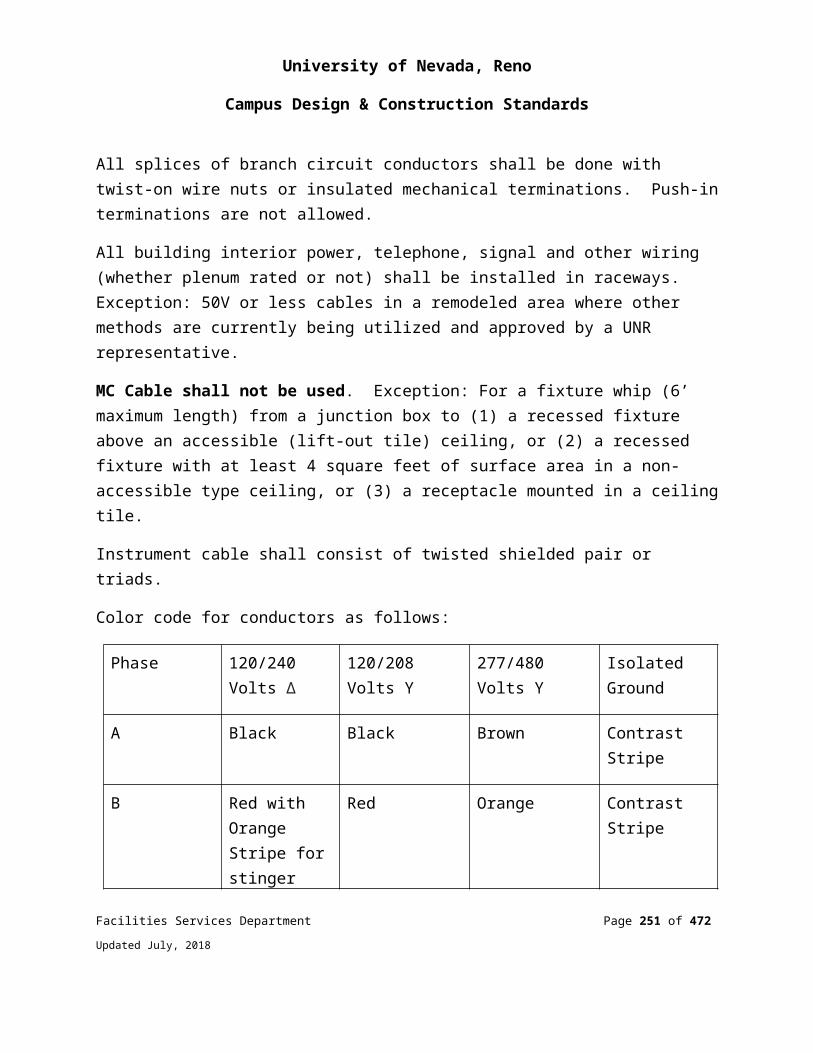
University of Nevada, Reno
Campus Design & Construction Standards
Piping InstallationUtility marking tape shall be installed over the entire length of the underground piping. Install plastic tape directly above the utility pipe at the elevation of approximately 12” above the top of pipe line.
Protect all non-metallic pipe, including but not limited to plastic piping, glass piping, and vitrified clay piping with detectable underground warning tape.
Detectable underground warning tape shall consist of 4.5 mil foil tape printed with pipe service, (i.e. “CAUTION GAS LINE BELOW,” “CAUTION WATER LINE BELOW,” etc.)
Tape buried up to 24” deep shall be a minimum of 3” wide.
Tape buried greater than 24” deep shall be a minimum of 6” wide.
Anchors shall be installed as per the manufacturer’s recommendations. Concrete shall be cast over the anchor plate and conduit and shall be large enough for firm anchorage into undisturbed soil.
All underground piping systems must be inspected by the Owner’s representative prior to backfilling.
Reference ANSI/AWWA Standard C651 for cleaning and disinfection procedures.
Test pressure gauges for a specific test shall have dials indicating not less than one and one half (1-1/2) times nor more than two (2) times the test pressure.
After installation of insulation, anchor blocks, and backfill, hydrostatic pressure shall be applied to 150 psig and allowed to stabilize to ground temperature while maintaining 150 psig, +/- 10 psi. After stabilization, pressure source shall be removed. Piping must hold150 psig, +/- 10 psi, for at least four (4) hours. Leaks shall be repaired and the test repeated if the pressure does not hold.
Owner must witness flushing, disinfection, and hydrostatic testing before acceptance.
PRODUCT STANDARDS AND MANUFACTURERSAll materials shall be certified new from factory. Pipe, fittings, and valves shall be made in the USA or Canada to AWWA and ANSI standards and suitably stamped. Piping components made in other countries shall not be used unless specifically approved in advance by the Project Coordinator.
Facilities Services Department Page 251 of 349
Updated July, 2018
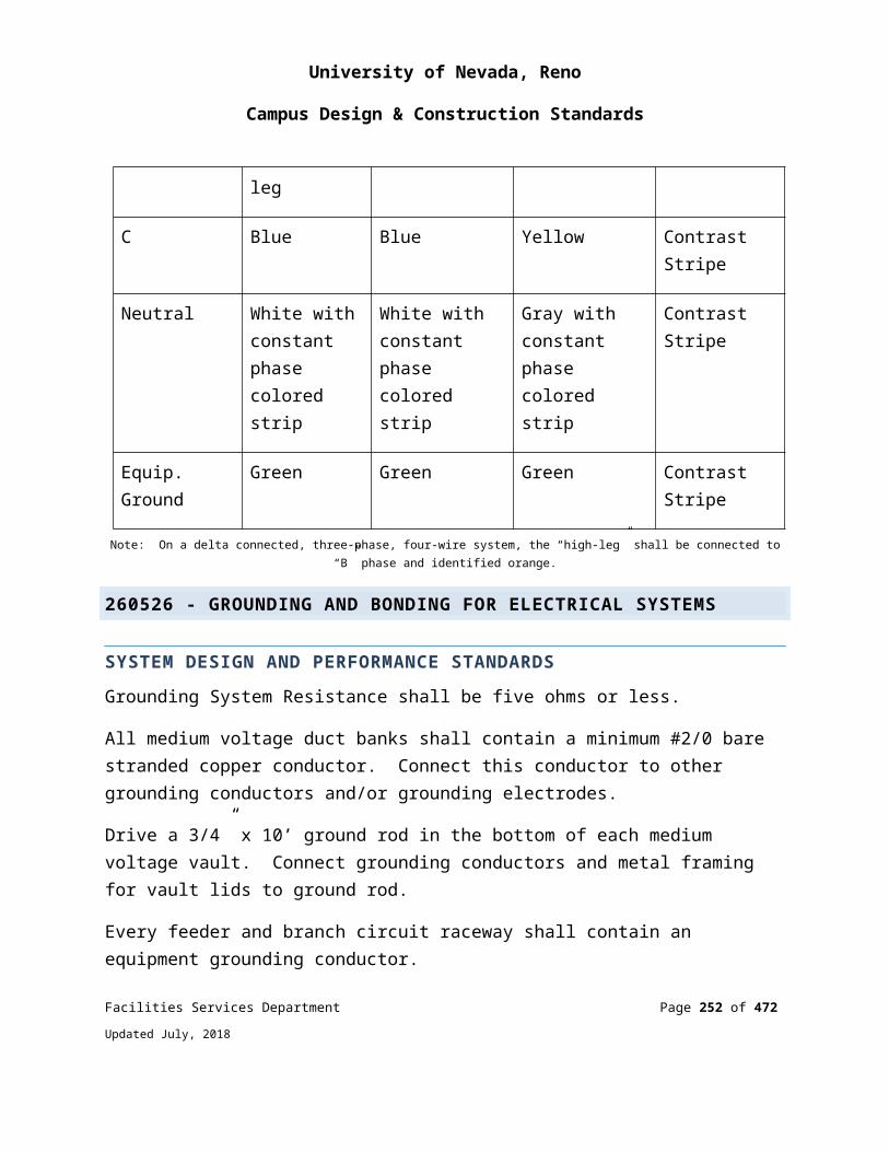
University of Nevada, Reno
Campus Design & Construction Standards
DELIVERY AND STORAGEContractor shall be responsible for inspecting materials delivered to site for damage.
Materials shall be stored on-site in enclosures or under protective coverings. Materials shall not be stored directly on ground.
Joint materials, fittings, valves, and gaskets shall be stored under cover out of direct sunlight.
HandlingPipe, fittings, valves and other accessories shall be handled in such a manner as to ensure delivery to the trench in sound, undamaged condition.
Special care shall be taken to avoid injury to coatings and linings on pipe and fittings. Damaged coatings and linings shall be repaired by the Contractor to the satisfaction of the Project Coordinator.
Field Quality ControlsThe project coordinator or his representative will conduct field inspections and shall witness all field tests specified in this section. The contractor shall perform field tests and provide labor, equipment, and incidentals required for testing. The contractor shall produce evidence, when required by the project coordinator, that any item of work has been constructed properly in accordance with the contract drawings and specifications.
All anchor blocks and restraints shall be complete prior to testing. Concrete supports shall be fully cured. Disinfection completed. All joints exposed for testing.
334100 -STORM DRAINAGE SYSTEM
SYSTEM DESIGN AND PERFORMANCE REQUIREMENTSPolyvinyl Chloride (PVC) Piping: Polyvinyl chloride pipe and fittings shall conform to ASTM D3034, SDR 35 with bell and spigot type rubber-gasket joints.
Reinforced Concrete Piping (RCP): Reinforced concrete pipe shall conform to ASTM C76 with tongue and groove or bell and spigot joints. Unless indicated otherwise on the plans, all reinforced concrete piping shall be Class III, 1350-D pipe.
Facilities Services Department Page 252 of 349
Updated July, 2018
University of Nevada, Reno
Campus Design & Construction Standards
Cast Iron Piping (CIP)Cast iron pipe and fittings shall conform to ASTM C74. Joints shall be rubber-gasket bell and spigot type.
Perforated UnderdrainPerforated underdrain shall be polyvinyl Chloride (PVC) pipe up to and including 15 inches in diameter, conforming to ASTM D3034, SDR 35.
Catch Basins and ManholesPrecast drainage structures shall conform to ASTM C478 and shall be of the size and shape shown on the drawings. Equivalent poured-in-place structures may be used at Contractor's option.
Manhole covers shall have 24" clear opening with the words "STORM DRAIN" in letters not less than 2" high cast into the cover (except where grated covers are shown on the drawings). Foreign made frames and covers will not be accepted.
Grates for catch basins shall have bars as shown on the plans suitable for use in areas with bicycle traffic.
Frames and grates for manholes and catch basins shall be match-marked in pairs before delivery to the job site. The grates shall fit into their frames without rocking.
Portland Cement ConcreteConcrete shall be Class A concrete.
Cement shall be Type II cement conforming to ASTM Designation C150.
Aggregate shall be 3/4" maximum size.
Water shall be clear and free from injurious amounts of oil, acid, alkali, organic matter or other deleterious substances.
Reinforcing bars shall conform to requirements of ASTM A615 Grade 40.
No admixtures will be allowed without prior approval of the Project Coordinator.
Facilities Services Department Page 253 of 349
Updated July, 2018

University of Nevada, Reno
Campus Design & Construction Standards
Pipe InstallationNo pipe shall be laid until the Construction Inspector approves the condition of the bottom of the trench. Pipe laying shall proceed upgrade with the spigot section of bell and spigot pipe pointing in the direction of flow.
All above-grade piping shall be securely attached to building wall or anchored to ground as required to maintain the grades shown on the drawings.
Slotted Edge DrainTrench excavation for the slotted edge drain will be completed during the roadway excavation phase at the cost of the Contractor.
Slotted edge drain and hugger bands shall be stored, handled and laid in such a manner as to prevent bruising, scaling or breaking of the surface or protective coating.
The slotted edge channel shall be primed and painted black prior to installation.
An alternative joint sealant or sealing method that will provide a watertight joint may be used provided said alternative sealant or method is approved, in writing, by the Project Coordinator.
The Contractor shall develop and propose a method for positioning the slotted edge drain to the specified line and grade shown on the plans prior to placing the concrete encasement. The top of the slotted edge drain shall not deviate from the specified horizontal position more than 1/2 inch per 20-foot section of pipe. The vertical position of the pipe shall conform to the slopes shown on the plans.
The pipe slot shall be covered with a heavy-duty tape or other covering approved by the Project Coordinator prior to placing the concrete encasement and any paving operations to prevent infiltration of material into the pipe.
Concrete Encasement for the slotted edge drain shall be placed in accordance with the details shown on the plans. Concrete Encasement shall be placed against the bottom and undisturbed sides of the trench or forms, and consolidated in a manner that will prevent floating or shifting of the pipe, and voids in, or segregation of, the concrete. Where necessary, earth plugs shall be constructed and compacted at the ends of the planned concrete backing to contain the concrete within the trench. Foreign material which falls into the trench, prior to or during placing of the concrete, shall be immediately removed.
Facilities Services Department Page 254 of 349
Updated July, 2018
University of Nevada, Reno
Campus Design & Construction Standards
Loads shall not be placed on the Concrete Encasement sooner than 8 hours after placement.
Poured In Place ConcreteNo pigment shall be used in curing compounds. All work shall be subject to inspection. No concrete shall be placed until the Construction Inspector has approved the forms and reinforcement.
Concrete shall not be dropped freely where reinforcing bars will cause segregation, nor shall it be dropped freely more than six feet (6'0"). Spouts, elephant trunks, or other approved means shall be used to prevent segregation.
Trench DrainThe trench drain shall be excavated and lined with filter fabric with a twelve inch (12") overlap on the top of the trench. The perforated pipe shall be installed with perforations down and backfilled with class I permeable material.
FIELD QUALITY CONTROL: Prior to the encasement of the slotted edge drain pipe, the Contractor shall have the Field Surveyor verify the accuracy of the alignment and grade of the pipe. All adjustments to the alignment and grade shall be the Contractor's responsibility before the pipe is encased.
GRADE ADJUSTMENTS TO SURFACE STRUCTURESFrames, Grates, and Covers Frames, grates and covers of all surface structures (manholes, drain inlets, catch basins, etc.) shall be adjusted to within 1/8” +/- of proposed finish grade. Grade rings shall be supplied and installed as required.
Frames of new or adjusted surface structures shall be supported by concrete with minimum dimensions as follows: six (6) inches wide by ten (10) inches deep.
Structures within Paved AreasA structure located in an area to be resurfaced with asphaltic concrete shall not be constructed to final grade until the adjacent pavement or surfacing has been compacted.
Facilities Services Department Page 255 of 349
Updated July, 2018
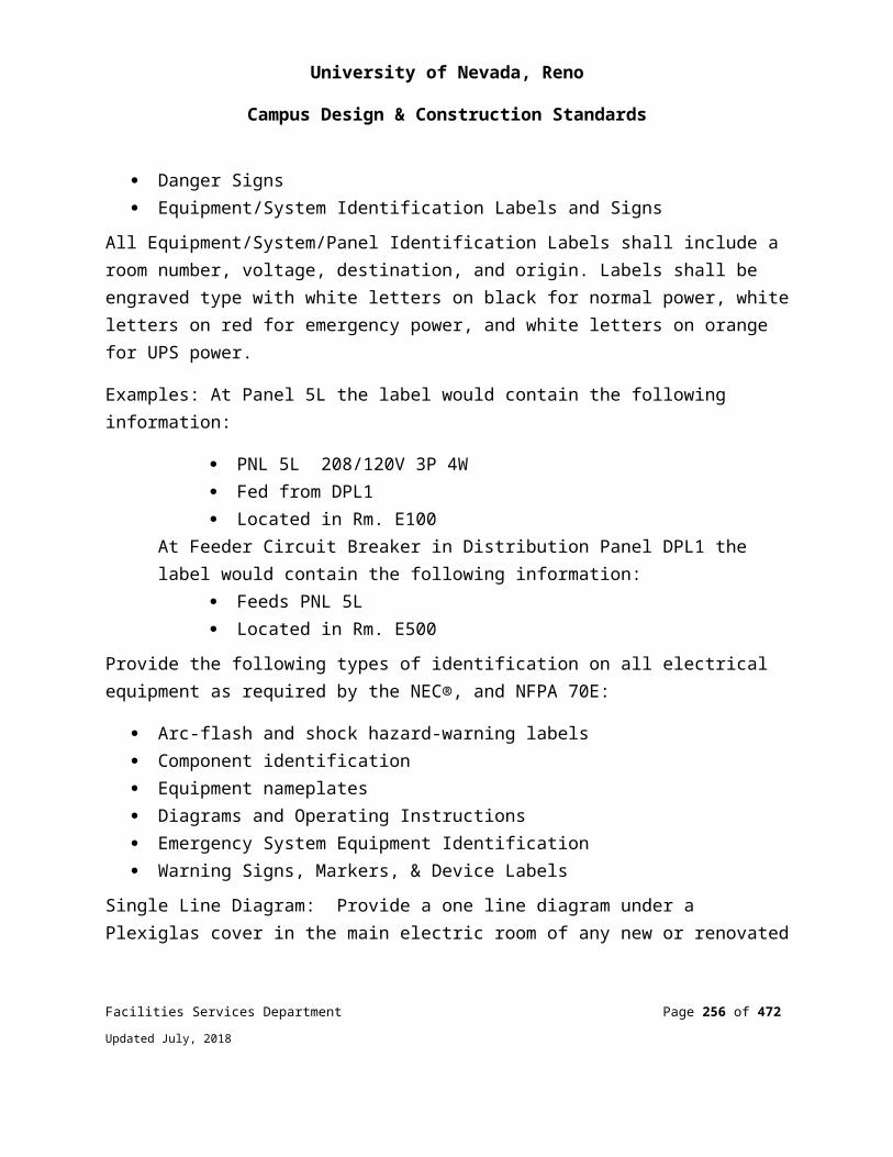
University of Nevada, Reno
Campus Design & Construction Standards
The Contractor shall be responsible for referencing structures prior to paving and locating them after paving operations are complete.
After asphaltic concrete resurfacing is complete, the asphalt shall be cut out six inches (6”) wider than the frames of all surface structures. Each frame shall then be raised to finished grade (sloped as necessary) and concrete shall be placed to approximately 1-1/2 inches below finish grade as noted above. After the concrete collar has cured, a tack coat shall be applied and asphaltic concrete placed to finish grade.
PRODUCT STANDARDS AND MANUFACTURERSDelivery and Handling Reinforced concrete pipe, precast concrete manhole sections, inlet frames and grating, and fittings must be handled carefully at all times. Only suitable and proper equipment and appliances shall be used for the safe loading, hauling, unloading, handling, and placing of materials. Material that is checked, spalled, or damaged shall not be installed and must be permanently removed from the job site.
335113 – NATURAL GAS PIPING SYSTEMS
SYSTEM DESIGN AND PERFORMANCE REQUIREMENTSThe piping at the building entrance shall have a California Seismic Gas Shutoff valve to automatically shutoff gas to the building in the event of an earthquake.
Above-grade natural gas lineSchedule 40, A53 carbon steel pipe with malleable iron threaded fittings 2 ½ inch diameter and larger and schedule 80 for less than 2 ½ inch for gas pipe inside buildings. To be tested with compressed air at 35 lbs. for 24 hours.
All gas lines shall be tested to fixture with monometer by a licensed contractor with a gas card.
337119 - ELECTRICAL UNDERGROUND DUCTS AND MANHOLES
SYSTEM DESIGN AND PERFORMANCE REQUIREMENTS
Facilities Services Department Page 256 of 349
Updated July, 2018

University of Nevada, Reno
Campus Design & Construction Standards
Electrical manholes and vaults located in streets shall have round covers rated for H20 wheel loading. Rectangular spring-loaded covers shall not be used.
End of Division 33
UTILITIES
Facilities Services Department Page 257 of 349
Updated July, 2018
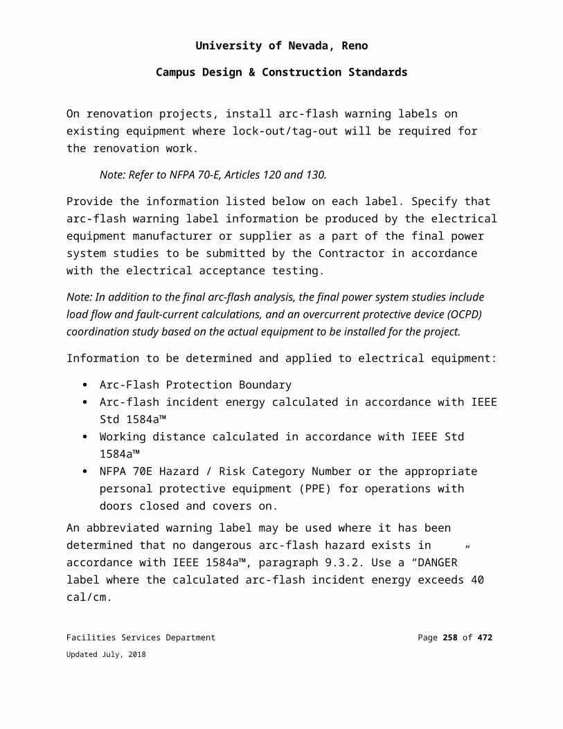
University of Nevada, Reno
Campus Design & Construction Standards
APPENDIX F
INDOOR ENVIRONMENTAL QUALITY POLICY
The following appendix includes information and standard drawings that are diagrammatic and are used only to convey intent.
MISSIONIn accordance with the university’s Indoor Environmental Quality Policy, the University will strive to provide buildings that provide an indoor environment conducive to productivity and learning.
POLICYIt shall be the policy of the University to provide favorable indoor environmental quality in University facilities and buildings. Indoor environmental quality includes indoor air quality, thermal comfort, lighting and day-lighting, acoustics and vibration, which enhance learning and work environments. This applies to the design, renovation, and maintenance of University facilities and buildings.
PURPOSEThe purpose of the University policy on Indoor Environmental Quality is to provide work and learning environments that promote the health of students, visitors, and staff, maximizes productivity, and enhances the learning environment.
Facilities Services and their design consultants incorporate designs, materials, and equipment which promote indoor environmental quality in the design of new UNR buildings.
Recommended Practices in support of Indoor Environmental Quality are as follows:
All new laboratory building designs will comply with the UNR Design and Construction Standards, Appendix H - Laboratory Safety Design Guidelines, and will meet a minimum standard equivalent to the latest LEED NC Certified Rating and Labs21 Environmental Performance Criteria.
Facilities Services Department Page 258 of 349
Updated July, 2018
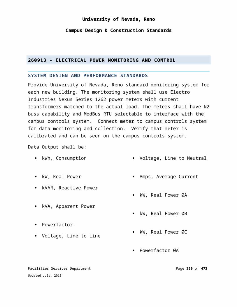
University of Nevada, Reno
Campus Design & Construction Standards
New building designs must provide an easily accessible area that serves the entire building and is dedicated to the separation, collection and storage of materials for recycling including (at a minimum) paper, corrugated cardboard, glass, plastics, and metals. (LEED NC 2.2, MR Prerequisite 1)
Before occupancy, new buildings should implement best practice commissioning procedures to ensure that fundamental building elements and systems are designed, installed and calibrated to operate as intended. Commissioning procedures shall include the following:
engage a commissioning team that does not include individuals directly responsible for project design or construction management;
review the design intent and basis of design documentation; incorporate commissioning requirements into the construction
documents; develop and utilize a commissioning plan; verify installation, functional performance, training and
operation and maintenance documentation. (LEED NC 2.2, EA Prerequisite 1)
Before occupancy and with all interior finishes installed, new buildings should undergo a building flush-out period to reduce possible indoor air quality contamination after construction completion. This requires supplying a total air volume of 14,000 cubic feet of outdoor air per square foot of floor area while maintaining an internal temperature of a least 60 degrees F and a relative humidity of less than 60%. (LEED NC 2.2 EQ 3.2)
New buildings will provide natural day-lighting where possible while minimizing direct sunlight and glare in teaching environments. (LEED NC 2.2 EQ 8.1, EQ 8.2 applies if views are added)
Campuses will prohibit smoking in newly designed buildings. (NRS 202.2491, LEED NC 2.2 EQ Prerequisite 1)
New buildings will provide indoor ventilation rates that meet the minimum requirements of ANSI/ASHRAE 62.1-2016 “Ventilation for Acceptable Indoor Air Quality”. (LEED NC 2.2 EQ Prerequisite)
New buildings will provide indoor thermal conditions that meet the minimum requirements of ANSI/ASHRAE 55-2013 “Thermal Environmental Conditions for Human Occupancy”.
Facilities Services Department Page 259 of 349
Updated July, 2018

University of Nevada, Reno
Campus Design & Construction Standards
END OF INDOOR ENVIRONMENTAL QUALITY POLICY
Facilities Services Department Page 260 of 349
Updated July, 2018
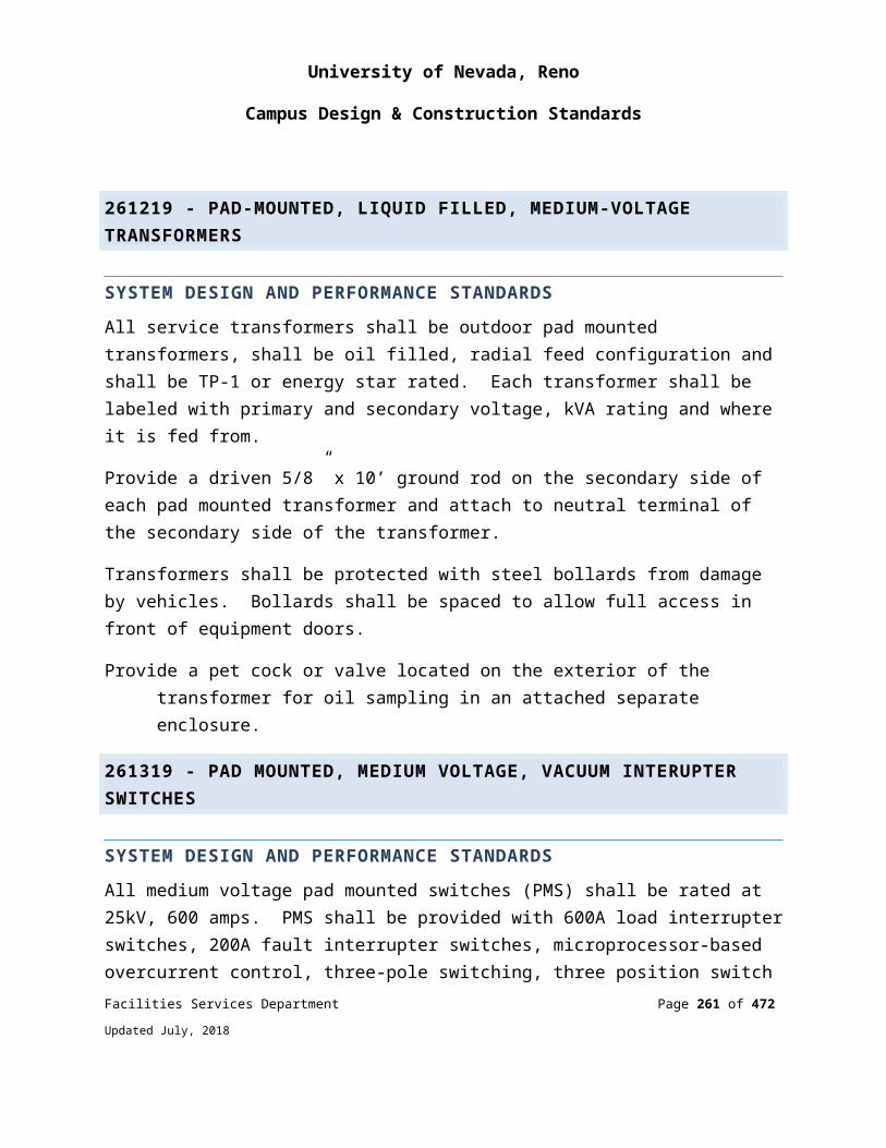
University of Nevada, Reno
Campus Design & Construction Standards
APPENDIX G
AUDIO AND VISUAL DESIGNCLASSROOM TECHNOLOGY
All classroom technology projects shall be coordinated with the University Department of Teaching and Learning Technologies (TLT) which is comprised of the Classroom Support and Instructional Design teams. TLT guides and standards can be found on the TLT website through this link:
Classroom Technology Design Standards
Facilities Services Department Page 261 of 349
Updated July, 2018
University of Nevada, Reno
Campus Design & Construction Standards
APPENDIX HLABORATORY SAFETY DESIGN GUIDELINES
The following appendix includes information and standard drawings that are diagrammatic and are used only to convey intent.
LABORATORY SAFETY DESIGN GUIDELINESINTRODUCTION
The University of Nevada Reno has a continuing need to modernize and upgrade its facilities. The resulting construction projects often have significant health and safety requirements due to regulatory oversight. In addition, the good practices followed in the design phases of a project can reduce the cost of ownership and difficulties encountered by users of a facility during the facility’s life cycle.
The Design Guide is a resource document for use by design professionals, faculty, and staff during the planning and early design phases of a project.
The requirements of the Design Guide apply to all laboratory buildings, laboratory units, and laboratory work areas in which hazardous materials are used, handled, or stored. It also addresses biological safety and ionizing and nonionizing radiation situations commonly found in laboratories. The University of Nevada, Reno believes this standard represents the minimum requirement; more stringent requirements may be necessary, depending on the specific laboratory function or contaminants generated.
The Design Guide is not "all inclusive." It covers neither all regulatory issues nor all design situations. In all cases, the campus Environmental, Health, and Safety (EH&S) Department shall be consulted on questions regarding health, safety, and environment.
GENERAL REQUIREMENTS FOR LABORATORIES
SCOPEThe primary objective in laboratory design shall be to provide a safe, accessible environment for laboratory personnel to conduct their work. A secondary objective is to allow for the maximum flexibility for safe research use. Undergraduate teaching laboratories require other specific design considerations. Therefore, health and safety hazards shall be anticipated and carefully evaluated so that protective measures can be incorporated into the design wherever possible. However, no matter how well designed
Facilities Services Department Page 262 of 349
Updated July, 2018

University of Nevada, Reno
Campus Design & Construction Standards
a laboratory is, improper use of its facilities will always defeat the engineered safety features. Proper education of the facility users is essential.
The General Requirements listed below illustrate some of the basic health and safety design features required for new and remodeled laboratories. Variations from these guidelines need approval from Campus Environment, Health, and Safety (EH&S) and Facilities Services.
BUILDING REQUIREMENTSDesigner Qualifications: The designer shall have the appropriate professional license in his/her area of expertise (either a registered architect or professional engineer in the State of Nevada).
Building Occupancy Classification: Occupancy classification is assigned to meet building code requirements and is to be based upon an assessment of a projected chemical inventory of the building.
BUILDING DESIGN ISSUESThe handling and storage of hazardous materials inherently carries a higher risk of exposure and injury. Therefore, it is important to segregate laboratory and non-laboratory activities. In an academic setting, the potential for students to need access to laboratory personnel, such as instructors and assistants, is great. A greater degree of safety will result when non-laboratory work and interaction is conducted in a space separated from the laboratory.
It is desirable to provide separate office spaces for laboratory employees.
Public access to laboratory personnel in office rooms with separate corridor access is highly desirable.
An automatically triggered main gas shutoff valve for the building shall be provided for use in a seismic event. In addition, interior manual shutoff valves shall be provided for both research and teaching areas.
Large sections of glass shall be shatter-resistant. In the event of a severe earthquake, as the glass in cabinets and windows breaks, the glass shards need to be protected to prevent injury.
Facilities Services Department Page 263 of 349
Updated July, 2018

University of Nevada, Reno
Campus Design & Construction Standards
LABORATORY DESIGN CONSIDERATIONSA process that integrates key decision makers (e.g., facilities, environmental health and safety, users, facility operators) into the design team shall be used.
Supply and exhaust systems shall meet the requirements listed in Division 23 of the Facilities Design and Construction Standards.
When office and lab spaces are connected, airflow shall enter via office spaces, and exit via hoods or other exhausts in lab spaces.
Laboratory bench standard depths are 30 inches for a wall bench, and 66 inches for an island bench. Bench lengths usually allow for 72 inches of free counter space per laboratory worker, in addition to the counter space allotted for equipment.
Deskwork areas in laboratories shall be separate from areas where hazardous materials are used. Specifically, fume-hood openings shall not be located opposite desk-type work areas.
Ensure that casework has no vibration, movement or loading limitations, is not seismic sensitive, interacts with laboratory equipment, is ergonomically designed, and is responsive to ADA concerns.
Floor loading shall be no more than 100–125 pounds/square foot. Heavy support equipment shall be located elsewhere.
Wet sprinklers in ductwork; and fume hoods are prohibited, avoid non-fireproof material in interstitial spaces.
Locate eyewash/safety shower near door. When feasible include a floor drain for the shower.
Where hazardous, bio-hazardous, or radioactive materials are used, each laboratory shall contain a sink for hand washing. The sink drain shall be connected either to a retention tank or building plumbing.
All work surfaces (e.g., bench tops, counters, etc.) shall be impervious to the chemicals and materials used in the laboratory. The countertop shall incorporate a lip to prevent run-off onto the floor. Lab benches shall be resistant to the chemical actions of chemicals and disinfectants.
The laboratory shall be designed so that it can be easily cleaned. Bench tops shall be a Facilities Services Department Page 264 of 349
Updated July, 2018
University of Nevada, Reno
Campus Design & Construction Standards
seamless one-piece design to prevent contamination. Laminate bench tops are not suitable. Penetrations for electrical, plumbing, and other considerations shall be completely and permanently sealed. If the bench abuts a wall, it shall be coved or have a backsplash against the wall. The countertop shall incorporate a lip to prevent runoff onto the floor.
Laboratory flooring in chemical use areas and other high hazard areas (such as biological containment facilities) shall be chemically resistant and one piece, and with covings to the wall.
The walls will be nonporous and painted with a durable, impervious finish in such a manner to facilitate decontamination. High-gloss paint is recommended.
Vented cabinets with electrical receptacles and sound insulation shall be provided for the placement of individual vacuum pumps, where their use is anticipated.
Laboratory areas shall be well lit to avoid spills and other accidents that could result in contamination buildup.
Provide storage racks for compressed gas cylinder storage.
If a house vacuum is provided, include traps or filters to prevent uptake of hazardous vapors by the vacuum system.
All new labs shall be equipped with a multi-level (ability to detect various types of gases) gas detection system with shut off valves incorporated into the system. Each system controller shall be clearly labeled with name of installing company and provide all necessary technical support contact information. The following Gas Detection Sequence of Operations shall be implemented:
Establish what lab needs gas detection, i.e. they use a certain amount of material or store a certain amount of gas.
Install detector. This will be tied into the fire system as a non-alarm point. Install a communicator with 8-zone minimum. All gas detection will be assigned to a zone on the communicator. Every lab will assign a responsible or contact person. When that device goes into alarm that person will be contacted. They will have
to set their own policies on how to handle the alarm.
Facilities Services Department Page 265 of 349
Updated July, 2018
University of Nevada, Reno
Campus Design & Construction Standards
If they feel it is a false alarm or a malfunction they will contact the Fire and Life Safety Department. If it is after business hours they will contact the monitoring company and the monitoring company will handle it.
HAZARDOUS MATERIALS DESIGN ISSUES Facilities shall be designed so that use of a respirator is not required for normal operations.
Where appropriate, general ventilation systems shall be designed, such that, in the event of an accident, they can be shut down and isolated to contain radioactivity or hazardous chemicals.
A pressure differential system shall be used to control the flow of airborne contamination. The flow shall always be from clean areas to contaminated areas, but it shall be recognized that similar areas may not always require the same ventilation characteristics.
The laboratory shall have a means of securing specifically regulated materials such as controlled substances regulated by the Drug Enforcement Administration (DEA), select agents regulated by Center for Disease Control (CDC), and radioactive materials (i.e., lockable doors, lockable cabinets etc.), where applicable.
Sufficient space or facilities shall be provided, so that materials that have unique physical or hazardous properties are stored safely, and materials that, in combination with other substances, may cause a fire or explosion or may liberate a flammable or poisonous gas, are kept separate. Separate space or facilities can include storage cabinets with partitions, acid cabinets, flammable cabinets, gas cabinets, etc.
Ventilated compressed gas cabinets shall be provided for labs where synthetic chemistry will be conducted or if gases with a NFPA health or flammability rating of 3 or 4 will be used or stored. Provide flammable and corrosive chemical storage cabinets.
ENTRIES, EXITS, AND AISLE WIDTH The main emergency egress from the laboratory shall have a minimum door width of 36 inches to facilitate departure in the event of an emergency.
Laboratories having a floor area of 200 square feet (18.6 m2) or more need two separate exits. All portions of the laboratory shall be within 75 feet of an exit.
Facilities Services Department Page 266 of 349
Updated July, 2018
University of Nevada, Reno
Campus Design & Construction Standards
Lab benches, furniture, or obstacles shall be placed so that there is at least 5 feet of clear egress. Lab benches shall not impede emergency access to an exit. This is also applicable to placement of other furniture and appliances such as chairs, stools, refrigerators, etc.
The space between adjacent workstations and laboratory benches shall be 5 feet or greater to provide ease of access. In a teaching laboratory, the desired spacing is 6 feet. Bench spacing shall be considered and included in specifications and plans.
The laboratory doors are to be automatically self-closing. Doors shall contain appropriate glazing or sidelights such that viewing into the lab is provided.
The self-closing laboratory doors are to be able to be opened with a minimum of effort as to allow access and egress for physically challenged individuals.
All exit and emergency doors serving hazardous occupancies shall swing in the direction of exit travel, regardless of the occupant load, and shall be equipped with panic hardware.
ELECTRICAL AND UTILITY ISSUESCircuit breakers shall be located outside the lab, but not in rated corridors. In the event of an emergency, the laboratory may be unsafe to enter.
Electrical receptacles above countertops and within six feet of sinks or other wet areas shall have GFCI circuit protection. Receptacles that are not readily accessible or receptacles for appliances occupying dedicated space that are cord-and-plug connected in accordance with NEC Section 400-7A (6–8), are exempt from this requirement.
Shutoff valves for gas and vacuum lines shall be located outside the lab, or near the lab exit.
Flexible connections shall be used for connecting gas and other plumbed utilities to any freestanding device, including but not limited to biosafety cabinets, incubators, and liquid nitrogen freezers. Biosafety cabinets shall not have natural gas piped to them. Seismic activity may cause gas and other utility connections to the biosafety cabinet to break off. Leaking natural gas is a fire hazard, and flexible connections minimize this potential hazard.
ACCESSIBILITY
Facilities Services Department Page 267 of 349
Updated July, 2018

University of Nevada, Reno
Campus Design & Construction Standards
Laboratory design shall include adapted workbenches as necessary:
A work surface that can be adjusted to 27 to 37 inches from the floor A 29-inch clearance beneath the top to a depth of at least 20 inches A minimum width of 36 inches to allow for leg space for the seated individual The utility and equipment controls are placed within easy reach
NONSTRUCTURAL SEISMIC HAZARD ABATEMENTAll shelves shall have a passive restraining system such as seismic shelf lips (3/4 inch or greater). The shelves themselves shall be firmly fixed so they cannot be vibrated out of place and allow the shelf contents to fall.
Flexible connections are preferred for connecting equipment and devices to utilities to allow for relative movement in a severe earthquake.
Any equipment, including but not limited to appliances and shelving to be installed by the contractor, which is 42 inches or higher and has the potential for falling over during an earthquake, or moving and blocking corridors or doors, shall be permanently braced or anchored to the wall and/or floor.
All compressed gas cylinders in service or in storage shall be secured to substantial racks or appropriate, sufficiently sturdy storage brackets with two chains, straps, or the equivalent, at 1/3 and 2/3 of the height of the cylinders to prevent their being dislodged during a violent earthquake. NOTE: Clamping devices are not acceptable as cylinder restraints.
ELECTRICAL SAFETY
SCOPE
This guide addresses some of the most common issues affecting the appropriate and safe installation of electrical systems for research laboratories. It is not intended to include all electrical installation requirements or good practices.
GENERAL DESIGN GUIDELINES 120-volt receptacles shall be located on every open wall such that there is not more
Facilities Services Department Page 268 of 349
Updated July, 2018

University of Nevada, Reno
Campus Design & Construction Standards
than 6 feet of wall space to a given receptacle. Quad outlet boxes are preferred over duplex. Lab bench areas shall be equipped with continuous receptacle molding (e.g., Plugmold) strips with receptacles spaced on 6–12-inch centers, or similarly continuous receptacles in raceway.
Provide receptacles of appropriate voltage and current ratings for known equipment in addition to the general convenience receptacles noted above.
Ground Fault Circuit Interrupter (GFCI) protection shall be provided for convenience receptacles located within 6 feet of a sink or other wet location. GFCI receptacles shall not be used for critical equipment such as refrigeration, sump pumps, or gas detectors. Use dedicated single receptacle outlets for such equipment.
Provide GFCI protection for receptacles that feed vessel-heating equipment such as strip heaters for vacuum vessels.
Each circuit breaker panel and similar equipment shall be labeled with a notification of an electrical arc flash hazard.
Circuit-breaker panels shall not be in the laboratory.
Each circuit and circuit breaker shall be sized to carry no less than 100% of the non-continuous current load plus 125% of the continuous current load for that circuit.
Laboratory convenience receptacle circuits shall be sized as 20-amp circuits, with no more than 13 duplex devices per circuit.
When designing circuit-breaker panels, at least 20–40% additional load capacity and circuit-breaker spaces than required by initial calculations shall be provided.
Fixed equipment that requires periodic maintenance shall be provided with lockable disconnect points (safety switch).
Electrical equipment and controls within fume hoods shall be provided with a disconnect switch within 15 feet.
Electrical receptacles and switches shall be located to minimize their exposure to spilled liquids.
Each branch circuit shall carry its own neutral conductor. Do not use multi-wire branch circuits that share a grounded (neutral) conductor.
Facilities Services Department Page 269 of 349
Updated July, 2018
University of Nevada, Reno
Campus Design & Construction Standards
Circuits serving sensitive Information Technology or data acquisition equipment shall be provided with an isolated grounding conductor in addition to the required equipment grounding conductor. This isolated conductor is to be terminated in an identified isolated receptacle or within the sensitive equipment.
Electrical wiring and equipment meeting the specific requirements of NFPA 70, Chapter 5, for classified locations shall be provided if substances used or stored in the laboratory can create a flammable or explosive atmosphere.
Rated clamps and conductors shall be provided to adequately bond containers, hoses, and other dispensing equipment to each other and the grounding system where flammable liquids are to be dispensed.
Electrical power shall not be commingled in a cable tray with other utilities (e.g., electrical, gas, water, etc.).
PRE-COMMISSIONING EVALUATION ACCEPTANCE Due to the potential for shock, serious injury, and fire, laboratories shall be inspected and approved by a qualified University staff electrical safety expert prior to beginning work.
LABORATORY VENTILATION AND FUME HOODS
(See Division 115313 of Facilities Design and Construction Standards)
COMMISSIONING AND PERFORMANCE TESTINGA written commissioning plan shall accompany design documents and be approved by the commissioning authority in advance of construction activities. The commissioning plan, along with the other project documents, shall be available to all potential suppliers and contractors prior to bid. The commissioning plan shall address the operation of the entire ventilation system where the hoods, laboratories, and associated exhaust and air supply ventilation systems are considered subsystems. The plan shall include, in addition to written procedures to verify or validate the proper operation of all system components:
Laboratory Chemical Hood Specification and Performance Tests Preoccupancy Hood and Ventilation System Commissioning Tests Preoccupancy Laboratory Commissioning Tests
Facilities Services Department Page 270 of 349
Updated July, 2018
University of Nevada, Reno
Campus Design & Construction Standards
Preliminary and final commissioning documents shall be issued to the appropriate parties by the University representative. The documents shall include:
Design Flow Specifications Laboratory and System Drawings for Final System Design Copy of Test and Balance Report Commissioning Test Data List of Ventilation System Deficiencies uncovered and the details of how (and if)
they were satisfactorily resolved
Operational deficiencies and other problems uncovered by the commissioning process shall be communicated to the responsible party (i.e., installer, subcontractor, etc.) for prompt correction.
The volumetric flow exhausted from a laboratory chemical hood shall be determined by measuring the flow in the exhaust duct, using industry-approved methods.
The hood static pressure shall be measured above the outlet collar of the hood at the flows required to achieve the design average face velocity.
The average face velocity, cross draft, response time, smoke containment, and tracer gas containment shall be determined by the methods described in the latest edition of ASHRAE 110, Testing Performance of Laboratory Fume Hoods. The area Industrial Hygienist shall approve results of fume hood commissioning tests.
EMERGENCY EYEWASH AND SAFETY SHOWER EQUIPMENT
SCOPE This guide presents criteria for eyewash and shower equipment for the emergency treatment of the eyes or body of a person who has been exposed to chemicals. The following types of equipment are covered: eyewash equipment, safety showers, combination shower and eyewash or eye/face-wash equipment.
APPLICATIONS Where the eyes or body of any person may be exposed to injurious, corrosive, or radioactive materials, suitable facilities for quick drenching or flushing of the eyes and body shall be provided within the work area for immediate emergency use. This includes areas where corrosive or injurious chemicals are used, such as:
Facilities Services Department Page 271 of 349
Updated July, 2018
University of Nevada, Reno
Campus Design & Construction Standards
Solutions of inorganic or organic acids or bases with a pH of 2.0 or less, or 12.5 or more;
Other organic or inorganic materials that are corrosive or irritating to eyes or skin (e.g., methylene chloride, phenol); or
Organic or inorganic materials that are significantly toxic by skin absorption (e.g., phenol, hydrazine).
Areas where corrosive chemicals are used in a closed system that can catastrophically fail and cause the chemicals to leak (i.e., liquid lead-acid battery-charging areas, or areas where pressurized systems with corrosive liquids are used);
Storage areas where breakable containers of injurious or corrosive materials (> 2.5 liters or ~0.6 gal) are handled outside their original shipping cartons;
Waste accumulation areas that contain corrosive waste materials; Areas where operations involve the use of air or water reactive liquids or solids; All open tray film-processing work areas using chemical developers and fixers; Acid washing work areas.
An emergency shower shall be provided at all work areas where, during normal operations or foreseeable emergencies, areas of the body may come into contact with a substance that is corrosive, severely irritating to the skin, or toxic by skin absorption. An emergency shower shall be provided at all work areas where formaldehyde solutions in concentrations greater than or equal to 1% are handled.
A plumbed eyewash shall be provided for all work areas where, during normal operations or foreseeable emergencies, the eyes of an employee may meet a substance that can cause corrosion, severe irritation, or permanent tissue damage, or is toxic by absorption. A plumbed eyewash shall be provided at all work areas where formaldehyde solutions in concentrations greater than or equal to 0.1% are handled. An eye wash must be provided in all wet labs, in addition to the criteria already listed on page 12, items 1.a. - i.
When chemicals are used in small quantities and the likelihood of exposure is limited, only an eyewash may be required. When the quantities are larger and significant splashing or spraying may occur, a safety shower shall also be required. EH&S shall be consulted to assist with these determinations. Eyewashes are also required where infectious agents are used.
Generally, eyewashes are not required in areas where:
Facilities Services Department Page 272 of 349
Updated July, 2018

University of Nevada, Reno
Campus Design & Construction Standards
Chemicals are stored in quantities less than 8 ounces (~240 mL) and used at room temperature at a rate of less than 2 ounces (~60 mL) per day. (Note: perchloric acid, hydrofluoric acid, formaldehyde concentrations ≥0.1 %, and the alkali metals and alkali metal compounds are not covered by this exemption.) EH&S shall be consulted to assist with this determination. Future use shall also be considered.
Compounds hazardous to the eye or skin are used in sealed systems at or below atmospheric pressure, and catastrophic failure or leakage is unlikely. However, an eyewash or shower may be appropriate if the system is filled, topped-off, or drained in other than a totally enclosed manner.
Materials hazardous to the eye or skin are stored in bulk in metal or plastic containers, and are not decanted.
EQUIPMENT REQUIREMENTSEmergency eyewash, safety shower, and combination units shall comply with the requirements of ANSI Z358.1
The eyewash shall have a plumbed drain to the sanitary sewer connection. When a sewer connection cannot be provided, a means shall be provided to empty test water into a bucket that can hold at least 10 gallons.
The 10-gallon capacity criterion comes from flowing water for 15 minutes at a flow rate of 0.4 gallons per minute.
Eyewash and safety shower water shall be delivered at a tepid temperature. For indoor systems, typical cold-water supply temperature is considered satisfactory. If the heating of hot water is required to provide tepid water, then a mixing valve to blend hot and cold water shall be provided.
The water supply to safety showers and combination units shall be controlled by a ball-type shutoff valve that is visible, well-marked, and accessible to shower testing personnel in the event of leaking or failed shower head valves. The valve shall not be located where an unauthorized person could easily shut it off.
The area around the safety shower shall be painted a bright color and shall be well lighted. Whenever possible, the floor immediately beneath the eyewash and emergency shower, and to a radius of 30 inches, shall be constructed of a nonslip surface and be a distinctive pattern and color to facilitate promoting a clear path of
Facilities Services Department Page 273 of 349
Updated July, 2018

University of Nevada, Reno
Campus Design & Construction Standards
access.
GENERAL LOCATIONLocate emergency eyewash facilities and safety showers in unobstructed and accessible locations requiring no more than 10 seconds for the injured person to reach along an unobstructed pathway. If both eyewash and shower are needed, they shall be located so that each can be used at the same time by one person. The pathway to the emergency eye wash or shower shall not require passage through a door and shall be on the same building level (no stairs or ramps). A travel time of 10 seconds is cited by ANSI as the comparable distance covered by an individual walking at a normal pace.
An emergency eyewash and safety shower station shall be located as near as practicable to laboratory fume hoods designed for handicapped access.
No obstructions, protrusions, or sharp objects shall be located within 16 inches from the center of the spray pattern of the emergency shower facility (i.e., a 32-inch clearance zone).
No electrical apparatus, telephones, thermostats, or power outlets shall be located within 18 inches of either side of the emergency shower or emergency eyewash facility (i.e., a 36-inch clearance zone) or within any area that may reasonably be considered a splash or flood zone. If 120-volt outlets or receptacles are present within 6 feet of an eyewash or shower, it shall be equipped with a GFCI.
PRE-COMMISSIONING TESTINGProper installation and operation of the equipment, within the specifications of the ANSI Z358.1 standard and the requirements of this section, shall be demonstrated prior to project closeout and facility occupation. Tags to allow periodic testing records to be kept shall be affixed to the showers and eyewash fountains. A commissioning checklist such as that included in Appendix 4-1 shall be used to document proper equipment installation and operation.
APPROVED EQUIPMENT
All emergency eyewash and safety shower equipment shall meet the requirements of ANSI Z358.1. The most versatile and complete emergency rinsing facility would include a combination unit with an emergency eye/face wash, a safety shower, and a drench hose. See Figure 1.
Facilities Services Department Page 274 of 349
Updated July, 2018

University of Nevada, Reno
Campus Design & Construction Standards
FIGURE 1Eyewash Safety Shower Illustration
ANSI Z358.1 is published by the International Safety Equipment Association, Arlington, VA www.safetyequipment.org. Used by permission.
HAZARDOUS MATERIALS STORAGE CABINETS
SCOPE This section applies to all campus facilities. It covers the design, construction, and installation of hazardous materials storage cabinets (including flammable liquid, corrosive material, and toxic material storage cabinets).
APPROVALS AND LISTINGS The purchase and installation of storage cabinets for both flammable liquids and toxic
Facilities Services Department Page 275 of 349
Updated July, 2018
University of Nevada, Reno
Campus Design & Construction Standards
materials shall be subject to review and approval of EH&S.
Flammable liquid storage cabinets shall be listed by a Nationally Recognized Testing Laboratory such as Underwriters Laboratories, Factory Mutual, or the State Fire Marshal.
DESIGN Laboratories that store, use, or handle more than 10 gallons of flammable or combustible liquids shall have one or more flammable liquid storage cabinets.
Flammable liquid storage cabinets shall not store more than 60 gallons of Class I flammable or Class II combustible liquids.
Flammable liquid storage cabinets shall be conspicuously labeled with the warning "FLAMMABLE — KEEP FIRE AWAY" in red letters on a contrasting background. Doors shall be well fitted, self-closing and equipped with a self-latching device.
When flammable or combustible liquids present multiple hazards, the storage requirements for each hazard shall be addressed.
Laboratories that store, use, or handle more than 10 pounds of highly toxic liquids or solids shall have one or more approved and vented toxic material storage cabinet.
Where necessary, vented cabinets shall be provided to store toxic materials, separated by hazard class. The vents shall be connected, preferably at the top of the cabinet to a supply ventilation system.
Corrosive/toxic material storage cabinet shelving shall be constructed to prevent spillage of contents with tight-fitting joints, a welded or riveted liquid-tight bottom, a door sill of at least 2 inches, and lockable cabinet doors that are self-closing and self-latching. Corrosive materials shall not be stored in metal cabinets unless the materials of construction are specifically treated to be corrosion-resistant.
Venting Hazardous Material Storage Cabinets Venting of storage cabinets is not required by Code and has not been demonstrated to be necessary for fire protection purposes. Additionally, if improperly performed, venting of a storage cabinet could compromise the ability of the cabinet to adequately protect its contents from involvement in a fire. However, there may be other health and safety considerations (e.g., odor control, control of potentially hazardous vapors) that dictate
Facilities Services Department Page 276 of 349
Updated July, 2018

University of Nevada, Reno
Campus Design & Construction Standards
that the interior of a cabinet be ventilated. Early in the design phase, the designer shall discuss ventilation of hazardous material storage cabinets with Facilities Services, Environmental Health and Safety, and the Fire Marshal. Flammable/combustible storage cabinets shall be vented in accordance with NFPA 30.
If a flammable liquid storage cabinet is ventilated, then it shall be connected through the lower bung opening to an exterior exhaust in such a manner that it will not compromise the specified performance of the cabinet. The other metal bung shall be connected to an air supply located outside of the fire control area.
Non-vented cabinets be sealed.
Toxic material storage cabinets used to store Highly Toxic materials more than an exempt amount shall be vented like flammable liquid storage cabinets.
Exhaust vent materials for hazardous material cabinets shall be compatible with contents of the cabinets. Vent materials for flammable liquid storage cabinets shall be resistant to high temperatures generated in a fire. Stainless steel, hard-soldered copper, and carbon steel are appropriate vent materials for flammable storage cabinets, provided the material is compatible with the intended service. Nonmetallic duct shall not be used to vent flammable storage cabinets. Compatible nonmetallic duct material, such as PVC, can be used for toxic material storage cabinet service. Polypropylene, which is combustible, is not appropriate vent duct material.
GENERAL INSTALLATION REQUIREMENTS Flammable liquid storage cabinets shall NOT be located near exit doorways, stairways, or in a location that would impede leaving the area.
Flammable liquid storage cabinets shall NOT be wall mounted.
Flammable liquid storage cabinets shall NOT be located near an open flame or other ignition source.
One room shall not contain more than three flammable liquid storage cabinets unless those groups of three cabinets are separated from each other by not less than 100 feet (30 m) – OR – if the building is protected by an automatic sprinkler system, the number of cabinets in any one group shall be increased to six.
Flammable and toxic/corrosive liquid storage cabinets shall be seismically anchored to prevent spillage of contents. Anchoring shall not compromise the integrity of the fire Facilities Services Department Page 277 of 349
Updated July, 2018
University of Nevada, Reno
Campus Design & Construction Standards
rating, i.e., drilling holes through a free-standing cabinet.
BIOSAFETY LABORATORIES
INTRODUCTIONContainment is defined as a safe method for managing hazardous materials or infectious agents in an environment where they are handled or maintained. The purpose of containment is to reduce or eliminate the exposure of hazardous materials or infectious agents to laboratory workers, other persons, and the environment.
Containment is divided into three levels: primary, secondary, and tertiary. Primary containment involves standard work practices to protect personnel and the immediate work area; secondary containment is the protection of the environment outside of the work area; and tertiary containment involves the use of highly specific biological barriers that prevent the survival of an organism outside of the host. The three main components of containment include work practices, safety equipment, and facility design. The guidelines listed here are for facility design and safety equipment used in the containment of infectious agents.
In recent years, laboratory designers and architects have constructed open laboratories instead of the more traditional closed laboratory. Regardless of an open or closed design, there are many factors that shall be considered before construction activities begin. These factors include, but are not limited to, the placement of HVAC systems, acoustic considerations, plumbing for sanitary drainage, laboratory drainage and vent systems, water supply systems, lighting, windows, access control and security, biological safety cabinets and fume hoods, storage, compressed gas systems, fire protection systems, and power for standard and emergency uses.
Before a proposed biosafety containment laboratory can be effectively planned, a risk assessment is needed to determine the containment conditions that will be required to mitigate the hazards associated with the proposed work. Risk assessments, conducted on a case-by-case basis, shall consider factors such as the types of bio-hazardous materials, the nature of the proposed work, laboratory and safety equipment needs, regulatory requirements, and the requirements of the University.
SCOPEThe guidelines presented below are for general laboratory use for Biosafety Levels
Facilities Services Department Page 278 of 349
Updated July, 2018
University of Nevada, Reno
Campus Design & Construction Standards
(BSL) 1, 2, and 3 (as defined by CDC/NIH) for biological research laboratories. Reference the latest version of the NIH Guidelines for Research Involving Recombinant DNA Molecules. And the latest version of Biosafety in Microbiological and Biomedical Laboratories. These design guidelines do not factor in American with Disabilities Act (ADA) issues, or recent changes to building or fire codes. If modifications are required due to any of these changes, biosafety considerations will be adjusted.
Since additional containment requirements may be imposed when working with specific agents, these design guidelines do not apply to the following:
Biocontainment facilities for animals Biocontainment facilities for plants Insectaries for disease vectors Biocontainment facilities for select agents Biocontainment facilities for U.S. Department of Agriculture–regulated animal
and plant pathogens Biocontainment facilities for large-scale (> 10 liters in a single vessel)
biological work Biological work in clean rooms, or biological work covered by the Food and
Drug Administration Biosafety Level-4 facilities
BASIC LABORATORY DESIGN FOR BIOSAFETY LEVELS 1 AND 2 LABORATORIES For research involving human pathogens, four biosafety levels (BSL-1 through BSL-4) are described in Section III of the CDC’s Biosafety in Microbiological and Biomedical Laboratories (BMBL) and Appendix G, Physical Containment of the NIH Guidelines for Research Involving Recombinant DNA Molecules. Each biosafety laboratory shall, at a minimum, meet the requirements for laboratory facilities as stated in the BMBL:
CDC Biosafety Publication.Floors Floors shall be durable and liquid tight.
Floor materials shall be nonabsorbent, skid-proof, resistant to wear, and resistant to the adverse effects of acids, solvents, and detergents.
For monolithic floors, either a 100-mm-high, readily cleanable, integrally coved sheet flooring base, or a readily cleanable, 100-mm-high, vinyl or rubber base shall be used.
Facilities Services Department Page 279 of 349
Updated July, 2018

University of Nevada, Reno
Campus Design & Construction Standards
Ceilings In BSL- 2 laboratories, drop ceilings shall use smooth, cleanable tiles (Mylar face with a smooth surface, or the equivalent).
Ceiling height shall accommodate a 14-inch clearance for biological safety cabinet(s). The ceiling shall be high enough to allow for canopy/thimble connection and the opening of thimble door(s), and so that the configuration of the ductwork will not interfere with airflow. A ceiling height of at least 10 feet is recommended. (Note: If the laboratory has a sprinkler system, local fire codes may require a clearance of 18 inches or more).
Offices and Eating AreasFormal offices shall not be included in the laboratory. An area shall be provided to allow researchers to record notes, possibly at a computer workstation with a laptop, or to fax materials.
Eating and drinking is generally prohibited in BSL-2 laboratories. An adjoining room shall be provided for eating and drinking in each laboratory suite. Eating and drinking is allowed only outside of the laboratory suite.
Windows Operable windows that open to the exterior, if present, shall be fitted with fly screens. Note: USDA does not allow operable windows.
Furniture and Casework Furniture and casework shall be sturdy, capable of supporting anticipated loading and uses.
Furniture and casework shall be spaced so that areas around and under benches, cabinets, and equipment are accessible for cleaning.
Bench tops shall be impervious to water, and resistant to acids, alkalis, organic solvents, and moderate heat.
Bench tops shall have marine/drip edging for spill control.
Fixed casework, if used, shall be sealed or caulked to the walls on installation to facilitate cleaning and prevent harborage for vermin.
Facilities Services Department Page 280 of 349
Updated July, 2018

University of Nevada, Reno
Campus Design & Construction Standards
Closed cabinets rather than open shelving shall be used for storage.
In BSL-2 laboratories, chairs and other furniture used shall be covered with a non-fabric that can be easily decontaminated.
Heating, Ventilation, and Air Conditioning (HVAC) Systems In BSL-2 laboratories, HVAC systems shall provide inward flow of air from rooms/areas of low hazard into rooms/areas of high hazard.
In BSL-2 laboratories, air shall not be recirculated to spaces outside of the laboratory or suite.
Emergency Eyewash An emergency eyewash shall be available in BSL-2 and BSL-3 laboratories.
Emergency eyewashes shall be plumbed to drain or installed over a sink to facilitate monthly testing.
Eyewashes shall be near splash hazards: less than 10 seconds’ travel distance, and no more than 22 m from any point in the laboratory. Good practice requires that no more than one door shall be opened in the line of travel.
Hand Washing Sink Each laboratory shall have a hand washing sink that is hands-free or automatically operated.
The hand washing sink shall be located near the exit, have chemical-resistant traps (for disinfectants), a coved backsplash, and a hot-cold water, pre-mixing faucet.
The hand washing sink shall be accompanied by a paper-towel dispenser and a hands-free soap dispenser mounted within easy reach.
ADDITIONAL DESIGN CONSIDERATIONS Provide provisions for locked storage in the building that meet the requirements of The Washoe County District Health Dept. WCDHD has established biohazardous waste regulations that apply to the university.
Provide storage for halogen and/or flammable chemical disinfectants.
Facilities Services Department Page 281 of 349
Updated July, 2018

University of Nevada, Reno
Campus Design & Construction Standards
For HIV, HBV, and HCV research laboratories and production facilities, follow Nevada State OSHA requirements.
BASIC LABORATORY DESIGN FOR BIOSAFETY LEVEL 3 LABORATORIES
The Facilities Services Department, in collaboration with EH&S, shall approve the location and design of any BSL-3 facility, and have final authority to authorize the commencement of BSL-3 work. The Institutional Biosafety Committee and EH&S have oversight of biosafety issues and facilities, and have authority to approve or stop work with bio hazardous materials.
The Biosafety Level-3 facility design and operational procedures shall be documented. The facility shall be tested for verification that the design and operational parameters have been met prior to operation. It is essential that the facility meets the required predetermined standards before putting the bio-containment facility into service.
GENERAL The laboratory shall consist of an anteroom and laboratory rooms.
The facility shall have gas-impermeable walls, ceilings, and floors. Air gaps under doors are acceptable for directional airflow. If the door gaps are sealed, the laboratory suite shall not leak gaseous decontamination materials. All penetrations of walls, ceiling, and floor shall be sealed.
Air balance shall be set so air from low hazard rooms flows into rooms with higher hazards, and entry into the laboratory requires passage through two self-closing, lockable doors.
All tall and/or heavy fixtures and equipment (e.g., biological safety cabinets, autoclaves, freezers, incubators, etc.) shall be fitted with a seismic anchoring system/device engineered to withstand earthquake stresses equal to 7.0 on the Richter scale.
The laboratory shall be designed for ease of maintenance, so that access to critical mechanical equipment (ventilation ducts, fans, piping, etc.) is outside containment. Access panels are only allowed in some retrofits, and in those cases, the panels shall be piano-type hinged and gasketed with gas-tight gaskets.
There shall be a room for large equipment decontamination. The room shall be capable
Facilities Services Department Page 282 of 349
Updated July, 2018
University of Nevada, Reno
Campus Design & Construction Standards
of being sealed for decontamination with gaseous formaldehyde or other gaseous or vaporous sterilant, and shall have a connection to the HVAC exhaust system.
CO2 and other specialty gases shall be plumbed from outside the laboratory into containment.
Work surfaces, floors, walls, and ceilings shall be designed, constructed, and finished to facilitate easy cleaning and decontamination.
The facility shall pass third-party inspection and tests to verify that design and operational parameters have been met. This shall be done by a third party who has previous experience in certifying BSL-3 laboratories.
The laboratory shall be located away from public areas and corridors used by laboratory personnel who do not work in the BSL-3 laboratory.
The laboratory shall be separated from unrestricted traffic.
An intercom or hands-free telephone shall be in each room and shall be connected to a location that has personnel available for emergency response at all times work is being performed in a BSL-3 laboratory. Generally, this is not a requirement.
Anteroom The anteroom shall consist of two doors for access to the laboratory.
Anteroom doors shall be interlocked or alarmed so only one door may be opened at a time, or placed sufficiently apart so that one person cannot open both doors at the same time. A manual override shall be provided for emergency exit.
Space shall be provided on or near the door for the conspicuous posting of the biohazard warning symbol, a list of personnel authorized to enter the area, and access rules.
Floors Floors shall be impermeable to liquids, be monolithic/seamless, or have welded seams. Seamless floors are highly recommended.
Floors shall be coved up the wall to a minimum of 4 inches.
Floors shall be easily cleaned, with chemical-resistant flooring (vinyl, or epoxy with
Facilities Services Department Page 283 of 349
Updated July, 2018
University of Nevada, Reno
Campus Design & Construction Standards
fiberglass reinforcement) with a slip-resistant, smooth, hard finish.
For monolithic floors, either a 100-mm-high, readily cleanable, integrally coved sheet flooring base, or a readily cleanable, 100-mm-high, vinyl or rubber base shall be used.
Walls
Walls shall be full height, extending to the structural deck above. For suites, suite walls shall meet this requirement rather than individual laboratory rooms in the suite.
Walls shall be durable, washable, and resistant to detergents/disinfectants (masonry, gypsum board, fiberglass-reinforced plastic, etc.).
Wall/ceiling penetrations shall be kept to a minimum and sealed with non-rigid, non-shrinking silicone or latex sealant; for fire rated walls, apply sealant before fire stopping.
Corner guards and bumper rails shall be provided to protect wall surfaces in high-traffic/impact areas. CeilingsThe ceiling shall be washable and resistant to detergents/disinfectants.
The ceiling shall be of monolithic construction (i.e., gypsum board, not removable tiles).
The ceiling shall be high enough over Class II A2 biological safety cabinets (BSCs) to allow for a canopy/thimble connection or the opening of canopy/thimble door(s).
Ceiling height shall be at least 10 feet to allow for 14 inches of clearance above BSCs.
Light fixtures shall be surface or independently mounted.
If recessed lighting is used, lighting penetrations shall be gasketed.
Offices and Eating Areas Eating and drinking is prohibited in BSL-3 laboratories. Formal offices shall not be included in the laboratory suite.
Doors Doors shall be self-closing and lockable.
Doors shall open inward (dependent on Fire Marshal requirements) or slide open. If sliders are used, they shall be made of safety glass, and a trackless design shall be Facilities Services Department Page 284 of 349
Updated July, 2018
University of Nevada, Reno
Campus Design & Construction Standards
considered. Note: Opening sliding doors causes less turbulence than standard doors. Pocket doors shall not be used.
Door between anteroom and corridor shall have door sweep for pest control.
Doors inside the suite shall allow for an approximately 3/4-inch clearance underneath the door for directional airflow.
Doors and frames shall be of solid finish construction, have required fire ratings, and include panic-hardware, hardware appropriate for high-use, and kick plates.
Windows Windows (safety glass, permanently closed, sealed with silicone or latex sealant) shall be installed so that the interior of the adjacent room, except change rooms and restrooms, is visible.
Operable windows shall not be allowed, to maintain air balance. Additionally, all windows shall be sealed.
Eyewash/Safety Shower An emergency eyewash shall be in each BSL-3 room.
Shower — Entry/Exit A shower may be required in ABSL-3 laboratories, insectaries, or with certain agents.
Plumbing All penetrations shall be perpendicular to the surface and shall be sealed to be gas-tight.
Penetrations shall be sealed with non-rigid, non-shrinking, silicone or latex sealant; for fire-rated walls, apply sealant before fire stopping.
All pipes into the BSL-3 laboratories shall be secured to prevent movement.
Fixtures shall be resistant to corrosion of bleach and other disinfectants.
Back-flow prevention devices shall be installed on all faucets (including industrial water).
6-inch P-traps shall be installed if significant changes in pressure could occur.
Facilities Services Department Page 285 of 349
Updated July, 2018
University of Nevada, Reno
Campus Design & Construction Standards
All pipes shall be identified by use of labels and tags.
Water supply control shall be located outside the containment area.
Plumbing shall discharge directly to a sanitary sewer.
Sinks Hand washing sinks shall be in each room near the exit. For suites that contain multiple laboratory rooms, a hand washing sink shall be available in each room. Knee – operated sinks shall not be installed; hands-free infrared sensors are preferred to avoid rip or bump hazards.
Sinks shall be hands-free. Infrared sensors are preferable, but may not be suitable for all laboratories. In cases where infrared sensors cannot be used, knee-operated sinks are preferable to foot-operated.
Autoclaves “Clean” side of pass-thru autoclave shall be in a room with security system to limit access to specific individuals. Install pass-thru autoclave using a bio-seal to seal wall penetration. Pass-through to the anteroom or support room; may be located outside the BSL-3 laboratory but within the building (only when no alternative is available).
Autoclave shall be equipped with interlocked doors.
The floor under the autoclave shall be monolithic, seamless, or heat-sealed, coved, and water-tight.
Floor penetrations, if essential, shall have a water and gas-tight seal at the monolithic floor.
The walls and hard ceiling shall have epoxy paint.
Exposed pipes shall be insulated.
The autoclave shall be seismically anchored.
Fire sprinkler heads, if in the canopy, shall be rated higher than the steam temperature.
A curbed corrosion-resistant basin shall be installed to prevent leakage.
A canopy hood is provided over the exit door of the autoclave to contain heat and
Facilities Services Department Page 286 of 349
Updated July, 2018
University of Nevada, Reno
Campus Design & Construction Standards
steam.
The installation shall be signed off by a professional engineer.
The autoclave room shall have a minimum of 10 air changes per hour.
Life Safety Fire alarms shall be clearly audible above ambient noise levels (low-frequency alarms for animal facilities).
A wall-mounted ABC Dry Chemical fire extinguisher shall be mounted near the exit door of the anteroom.
Laboratory-safe refrigerators shall be used to store flammable/ combustible materials. Refrigeration is generally not required for chemicals used in BSL-3 labs.
Alarms Alarms shall be provided for:
Fire hazard Ventilation failure (exhaust fan failure) Differential pressures below 0.05” wg –80°C freezers Incubators (based on user programming)
Local and remote alarms are required for facility access control systems and facility security systems.
Alarms shall be connected to the building control system.
Alarms shall be audible and visible throughout the laboratory. Exhaust fan/pressure differential failure alarms shall be audible/visible to personnel prior to entry into the laboratory or suite.
Alarms shall be differentiated from each other so that each can be easily identified.
Alarms shall be on UPS power.
Vacuum System/Pump Vacuum lines are protected with liquid disinfectant traps and HEPA filters, or their
Facilities Services Department Page 287 of 349
Updated July, 2018

University of Nevada, Reno
Campus Design & Construction Standards
equivalent. Filters shall be replaced as needed. An alternative is to use portable vacuum pumps (also properly protected with traps and HEPA filters).
If an individual vacuum pump is used, it shall be in the laboratory. Noise and maintenance issues shall be addressed.
Electrical Emergency power shall be provided for:
HVAC (including controls) Alarms Security /access control systems Emergency lighting Biological safety cabinets Storage freezers Incubators Facility security systems
UPS power shall be provided to alarms, and when possible, to biological safety cabinets, facility access control systems, and the facility security system.
An independent circuit shall be provided for each biological safety cabinet.
Wall/ceiling penetrations shall be kept to a minimum and shall be sealed with non-rigid, non-shrinking, silicone or latex sealant; for fire-rated walls, apply sealant before fire stopping.
Junction boxes shall be cast and/or sealed airtight (e.g. closed cell foam compatible with gaseous formaldehyde).
Light fixtures are surface or pendent-mounted. Light fixtures that are easily cleanable shall be used.
Circuit breakers are located outside containment and are labeled.
Heating, Ventilation, and Air Conditioning (HVAC) Systems A differential pressure monitor to determine proper directional (inward) air flow shall be installed at each suite and laboratory entrance, and the monitor shall provide a local audible alarm. Pressure differentials shall be monitored remotely to track performance and communicate off-normal conditions.
Facilities Services Department Page 288 of 349
Updated July, 2018
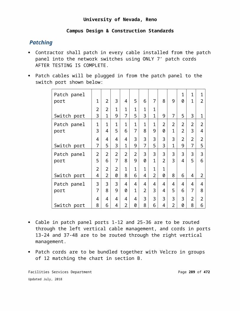
University of Nevada, Reno
Campus Design & Construction Standards
For Class II, type B2 biosafety cabinets, the cabinet exhaust fan shall be interlocked with the cabinet supply air to prevent positive pressurization of the interior of the cabinet if the exhaust fan fails.
In most cases, the HVAC system shall be Constant Air Volume (CAV). Variable Air Volume (VAV) is not recommended.
Electronic direct digital controls are used to manage the system.
Recirculation of exhaust air shall not be allowed.
A dedicated exhaust system is required.
The outside exhaust shall be dispersed away from occupied areas and air intakes, or the exhaust shall be HEPA-filtered. HEPA-filtered exhaust is strongly recommended. Filter housing shall allow in situ decontamination of filters (gas-tight dampers are required upstream and downstream), as well as performance testing of the HEPA filters.
An exhaust HEPA may be required.
Air supply and exhaust system capacity shall be ≥ 125% of the laboratory’s requirements to provide for future adaptability and flexibility.
The HVAC system shall create directional airflow drawing air from rooms/areas of low hazard into rooms/areas of higher hazard.
Inward directional airflow shall be maintained by providing 15% more flow of exhaust airflow than supply air (USDA) (minimum 200 cfm – Jennette, 2000), and sufficient to maintain the differential pressure between rooms in 0.05 – 0.20” Wg range.
The air balance shall accommodate biological safety cabinet canopy/thimble connection or Class II type B2 cabinet exhaust requirements.
Inward directional airflow shall be able to be verified before entry. Install a device(s) to indicate/confirm directional airflow into the laboratory (e.g., 0 – 0.20” Wg magnehelic gauges, digital differential pressure monitors, or both).
The BSL-3 lab shall not become positively pressured if the exhaust system fails. The supply air fan must be interlocked with the exhaust air fan to prevent the BSL-3 laboratory space form becoming positively pressurized. Interlock of the supply and exhaust fans is not specifically stated in the current edition of the BMBL but is required
Facilities Services Department Page 289 of 349
Updated July, 2018
University of Nevada, Reno
Campus Design & Construction Standards
to ensure “sustained directional airflow” as required by the BMBL; therefore, an interlock is a requirement for a BSL-3 lab.
Exhaust ductwork shall not be positively pressurized.
Supply and exhaust dampers shall be gas-tight and closable from outside the facility to facilitate decontamination with gaseous paraformaldehyde.
Local visual and audible ventilation system failure alarms are required for laboratory personnel.
Air supply diffusers shall be located so that airflow at the biological safety cabinet face is unaffected (laminar diffusers preferred).
Ductwork shall be located external to the laboratory; if exposed in the laboratory, ductwork is clear of walls to allow for cleaning, maintenance, and leak testing.
Ductwork shall be gas-tight 316 stainless steel up to the HEPA filter (if present). This is usually not required for BSL-3 but may be considered.
All ducts shall be constructed in a leak-tight manner with seams and joints usually welded airtight. The Biosafety Officer will determine if exhaust ductwork is to be welded.
If the exhaust ductwork is welded, recommend welded joints for all connections except for the damper(s) (use flange and bolt connections for quick change-out in the future).
Limit elbows whenever possible to reduce the amount of background noise generated.
HEPA Filters The Environmental Health & Safety and Facilities Services Department may determine that a HEPA-filtered exhaust system is not necessary after complete evaluation of the on-site conditions, including evaluations of:
Local code Facility/building Infectious agent Conditions of the experiment or nature of animal used An engineering study of the exhaust air plume that demonstrates that air shall be
directed away from occupied areas and air intakes
HEPA filters, if provided on the exhaust system, shall be "bag-in, bag-out," and the
Facilities Services Department Page 290 of 349
Updated July, 2018
University of Nevada, Reno
Campus Design & Construction Standards
housing shall accommodate gas decontamination and filter testing (gas-tight dampers and housing).
HEPA filters shall be located as close to the laboratory as practical to minimize the length of potentially contaminated ductwork.
HEPA filter housings shall be no more than five-feet high to facilitate filter change-out.
When HEPA filters are installed, a magnehelic gauge or other pressure-monitoring device shall be installed, with the display placed in the most accessible location that is practical, to measure pressure drop across the filters.
A HEPA may be required on the autoclave exhaust, ultracentrifuge vent, and sewer vent.
Arrangements shall be made to permit periodic leak testing of exhaust system HEPA filters. The system shall comply with ASME AG-1.
Laboratory Furniture and Casework Bench tops shall be impervious to water and resistant to acids, alkalis, organic solvents, and moderate heat.
Fixed casework, if used, shall be sealed/caulked to the walls on installation to facilitate cleaning and prevent harborage for vermin.
Closed cabinets rather than open shelving shall be used for storage.
In BSL-2 and 3 laboratories, chairs and other furniture shall be covered with a non-fabric material that can be easily decontaminated. NIH Guidelines; USDA; NIH Design Guidelines
Security Provide programmable security system at entrance to suites and interior laboratories to control access by specific individual. UNR Biosafety Officer/Select Agent Responsible Official shall be consulted to determine specific security needs.
Access controls be provided to record entry and exit times and dates.
Access to mechanical and support areas shall be limited.
Security measures shall equal or exceed the guidance set forth in the latest version of
Facilities Services Department Page 291 of 349
Updated July, 2018

University of Nevada, Reno
Campus Design & Construction Standards
the CDC-NIH’s Biosafety in Microbiological and Biomedical Laboratories. Facility security measures for BSL-3 laboratories that will be used for work involving select agents (most BSL-3 labs) must comply with CDC/USDA select agent regulation security measures. Note: USDA has specific security requirements; refer to USDA Security Policies and Procedures for Biosafety Level-3 Facilities, DM 9610-001.
Communications An intercom or hands-free telephone shall be in each room and shall be connected to a location that has personnel available for emergency response at all times work is being performed in a BSL-3 laboratory.
Wall/ceiling penetrations shall be kept to a minimum and shall be sealed with non-rigid, non-shrinking, silicone or latex sealant; for fire-rated walls, apply sealant before fire stopping.
COMMISSIONING Certification of the BSL-3 laboratory (different than building commissioning) shall be performed by independent party chosen by EH&S and Facilities Services that has previous experience in testing and certifying BSL-3 labs.
Commissioning shall be performed by a third party in the presence of the Facilities Services Department and Environmental Health & Safety Offices.
A properly designed and constructed bio-containment facility, including its structural and mechanical safety systems, shall meet predetermined performance criteria and be operational upon completion of construction. The integrity of the critical components of the biological containment systems shall be verified by the testing and certification requirements.
Certification of the facility, including structural components and safety systems, shall be included as part of the overall commissioning processes normally undertaken to verify that the design and construction meet applicable standards, and that the facility can operate in accordance with the design intent.
Commissioning testing shall also be performed without degradation to the facility or mechanical system that is being tested.
BSCs shall be certified in accordance with NSF 49 after the BSC is anchored in its final location. Facilities Services Department Page 292 of 349
Updated July, 2018

University of Nevada, Reno
Campus Design & Construction Standards
All HEPA filters shall be tested to meet NSF 49 after installation.
Integrity of epoxy coatings may be tested using ASTM D4541 Standard Test Method for Pull-Off Strength of Coatings Using Portable Adhesion Testers.
The autoclave installation shall be found to be proper as attested by the sign-off of a Professional Engineer.
The autoclave shall be tested to verify that it meets specified standards:
Thermometers are calibrated Clocks and timers are calibrated Biological indicators are used to verify the autoclave’s effectiveness
The operation of backflow preventers shall be verified
The ventilation system shall be tested by:
Ventilation ductwork and HEPA housings shall pass pressure-decay testing under ASHRAE SMACNA Standard 126-2000 (Method of Testing HVAC Air Ducts). Pressure-decay testing of ductwork and filter housing is not normally required for BSL-3 labs.
Measurements of airflow at each supply and exhaust diffuser Smoke testing to visually verify limited turbulence at face of BSC Smoke testing to visually verify airflow from areas of low hazard to areas of
higher hazard Verification that air system failure alarms (exhaust, supply, room pressure)
function and annunciate properly Air balance report shall be provided to and verified by the Facilities Officer
Additional environmental protection (e.g., personnel showers, HEPA filtration of exhaust air, containment of other piped services, and the provision of effluent decontamination) shall be considered if recommended by the agent summary statement, as determined by risk assessment, the site conditions, or other applicable federal, state, or local regulations.
BIOSAFETY IN MICROBIOLOGYAND BIOMEDICAL LABORATORIES (BMBL)
REQUIREMENTSFacilities Services Department Page 293 of 349
Updated July, 2018
University of Nevada, Reno
Campus Design & Construction Standards
Biosafety Level 1 A door.
A sink for hand washing.
Designed for easy cleaning.
Bench-tops impervious to water and resistant to acids, alkalis, organic solvents, moderate heat, and chemicals used to decontaminate.
Laboratory furniture capable of supporting anticipated loading and uses.
Accessible spaces between and under benches, cabinets, and equipment.
Windows fitted with fly screens (if they can be opened).
Biosafety Level 2 BSL-1 Requirements and Good Practices.
Lockable, self-closing, fire-rated door that opens inward.
Located away from public areas.
Appropriately installed biological safety cabinets.
Readily available eyewash station that complies with the requirements of Chapter 4 of this Guide.
Adequate illumination for all activities.
Consideration of inward flow of air without recirculation to spaces outside of the laboratory.
Seismically anchored autoclaves.
Good Practice for BSL-2 includes:
Floors with a slip-resistant, smooth, hard finish; are liquid-tight or monolithic/seamless or have welded seams; and that have a wall coved up 4-inches, or a cove-base installed to create a water-tight seal to the floor.
Walls that are durable, washable, and resistant to detergents/disinfectants (use durable glossy acrylic or epoxy paint or equivalent).
Facilities Services Department Page 294 of 349
Updated July, 2018

University of Nevada, Reno
Campus Design & Construction Standards
Protection of exposed corners and walls from damage by carts. Wall/ceiling penetrations kept to a minimum and sealed with fire-retardant
material. Douse shower unit in near proximity. The safety shower/eyewash shall comply
with the requirements of Chapter 4 of this Guide. Floor drain for autoclave. A canopy hood located over each end of the autoclave.
Biosafety Level 3 BLS-2 Requirements and Good Practices.
The laboratory is separated from areas that are open to unrestricted traffic flow within the building, and access to the laboratory is restricted. Passage through a series of two self-closing doors is the basic requirement for entry into the laboratory from access corridors. Doors shall be lockable. A clothes-changing room may be included in the passage way.
Each laboratory room contains a sink for hand washing. The sink is hands-free or automatically operated, and is located near the room exit door.
The interior surfaces of walls, floors, and ceilings of areas where BSL-3 agents are handled are constructed for easy cleaning and decontamination. Seams, if present, shall be sealed. Walls, ceilings, and floors shall be smooth, impermeable to liquids, and resistant to the chemicals and disinfectants normally used in the laboratory. Floors shall be monolithic and slip-resistant. Consideration shall be given to the use of coved floor coverings. Penetrations in floors, walls, and ceiling surfaces are sealed. Openings such as those around ducts and the spaces between doors and frames are capable of being sealed to facilitate decontamination.
Bench-tops are impervious to water and are resistant to moderate heat and the organic solvents, acids, alkalis, and those chemicals used to decontaminate the work surfaces and equipment.
Laboratory furniture can support anticipated loading and uses. Spaces between benches, cabinets, and equipment are accessible for cleaning. Chairs and other furniture used in laboratory work shall be covered with a non-fabric material that can be easily decontaminated.
All windows in the laboratory are closed and sealed.
A method for decontaminating all laboratory wastes is available in the facility and
Facilities Services Department Page 295 of 349
Updated July, 2018
University of Nevada, Reno
Campus Design & Construction Standards
utilized, preferably within the laboratory (i.e., autoclave, chemical disinfection, incineration, or other approved decontamination methods). Consideration shall be given to means of decontaminating equipment. If waste is transported out of the laboratory, it shall be properly sealed and not transported in public corridors.
Biological safety cabinets are required and are located away from doors, from room supply louvers, and from heavily traveled laboratory areas.
A ducted exhaust air ventilation system is provided. This system creates directional airflow, which draws air into the laboratory from "clean" areas and toward "contaminated" areas. The exhaust air is not recirculated to any other area of the building. Filtration and other treatments of the exhaust air are not required, but may be considered based on site requirements and specific agent manipulations and use conditions. The outside exhaust shall be dispersed away from occupied areas and air intakes, or the exhaust shall be HEPA-filtered. Laboratory personnel shall verify that the direction of the airflow (into the laboratory) is proper. It is recommended that a visual monitoring device that indicates and confirms directional inward airflow be provided at the laboratory entry. Consideration shall be given to installing an HVAC control system to prevent sustained positive pressurization of the laboratory. Audible alarms shall be considered to notify personnel of HVAC system failures.
HEPA-filtered exhaust air from a Class II biological safety cabinet (BSC) can be recirculated into the laboratory if the cabinet is tested and certified at least annually. When exhaust air from Class II BSCs is to be discharged to the outside through the building exhaust air system, the cabinets shall be connected in a manner that avoids any interference with the air balance of the cabinets or the building exhaust system (e.g., an air gap between the cabinet exhaust and the exhaust duct). When Class III BSCs are used, they shall be directly connected to the exhaust system. If Class III BSCs are connected to the supply system, it is done in a manner that prevents positive pressurization of the cabinets
Continuous flow centrifuges or other equipment that may produce aerosols are contained in devices that exhaust air through HEPA filters before discharge into the laboratory. These HEPA systems are tested at least annually. Alternatively, the exhaust from such equipment may be vented to the outside if it is dispersed away from occupied areas and air intakes.
Vacuum lines are protected with liquid disinfectant traps and HEPA filters, or their equivalent. Filters shall be replaced as needed. An alternative is to use portable
Facilities Services Department Page 296 of 349
Updated July, 2018
University of Nevada, Reno
Campus Design & Construction Standards
vacuum pumps (also properly protected with traps and filters).
An eyewash station is readily available inside the laboratory.
Illumination is adequate for all activities, avoiding reflections and glare that could impede vision.
The Biosafety Level-3 facility design and operational procedures shall be documented. The facility shall be tested for verification that the design and operational parameters have been met prior to operation. Facilities shall be re-verified, at least annually, against these procedures as modified by operational experience.
Additional environmental protection (e.g., personnel showers, HEPA filtration of exhaust air, containment of other piped services, and the provision of effluent decontamination) shall be considered if recommended by the agent summary statement, as determined by risk assessment, the site conditions, or other applicable federal, state, or local regulations.
Laboratory separated from areas that are open to unrestricted traffic flow within the building, and access to the laboratory is restricted.
BIOLOGICAL SAFETY CABINETS Features All biological safety cabinets (BSCs) shall meet the specifications within the most recent edition of the National Sanitation Standard 49 – Class II (Laminar Flow) Biohazard Cabinetry.
UV lights are not required nor recommended.
All BSCs shall be seismically anchored.
All biological safety cabinets will be selected prior to HVAC design and be approved by the Facilities Officer.
Class II A2 BSCs are recommended for most biohazard work, and are preferable to Class II A1 because of the negative plenum design of the A2. At a minimum, Class II A1 or Class II A2 BSCs shall be used for biohazard work. Class I BSCs will not be approved.
Class II A1 BSCs shall not be directly connected to the exhaust system.
Facilities Services Department Page 297 of 349
Updated July, 2018
University of Nevada, Reno
Campus Design & Construction Standards
Class II A2 BSCs shall connect to the exhaust system via an air gap (canopy or thimble), or exhaust directly into the laboratory. The canopy/thimble connection shall provide access to the exhaust filter for testing of the HEPA filter. The canopy/thimble connection shall have a ribbon streamer or like device attached to the edge to indicate the direction of flow.
Class II B2 BSCs shall be used for bio-hazardous work involving greater-than trace amounts of flammable, volatile, or toxic chemicals. Class II B2 BSCs shall be directly (hard) connected to the exhaust system. Class II B2 BSCs shall have fan interlocks, so that when the exhaust fan is manually shut off, the internal blower of B2 BSCs shuts off.
Class III BSCs shall be directly (hard) connected to an exhaust system dedicated to that Class III BSC. If they are connected to the supply system, it is done in a manner that prevents positive pressurization of the BSC. Class III BSCs have two HEPA filters in the exhaust system.
Class II B2 and Class III BSCs shall not be manifolded with other types of BSCs or fume hoods. Class II B2 BSCs can be manifolded with other Class II B2 BSCs.
Redundant exhaust fans shall be supplied for Class II B2 BSC exhausts, since the BSC’s containment depends on the building’s exhaust system.
14-inch clearance above the cabinet shall be provided for accurate air velocity measurement across the exhaust filter surface and for exhaust filter changes. When the BSC is hard-ducted or connected by a canopy connection to the ventilation system, adequate space shall be provided so that the configuration of the ductwork will not interfere with airflow.
Natural gas is not recommended. If provided, the gas line shutoff valve shall be easily accessible. The gas supply line shall have flex gas lines and a pipe union between the shutoff valve and the wall.
Where BSCs are directly (hard) connected to the exhaust system, an audible and visual alarm system to alert the user indicating the loss of exhaust flow in the external duct shall be used.
Location The BSC shall be located at least six feet from doors and high-traffic areas, and such that air supply diffusers do not affect airflow at the BSC face.
Facilities Services Department Page 298 of 349
Updated July, 2018

University of Nevada, Reno
Campus Design & Construction Standards
BSCs shall be placed out of the direct traffic pattern of the laboratory. Air supply diffusers or exhaust vents shall not be placed directly over or in front of BSCs where the movement of air can affect the airflow of the cabinet.
The BSC shall be located away from the entry to the laboratory (i.e., the rear of the laboratory away from traffic), since people walking parallel to the face of a BSC can disrupt the air curtain. The air curtain created at the front of the cabinet is quite fragile, amounting to a nominal inward and downward velocity of 1 mph. Open windows, air supply registers, or laboratory equipment that create air movement (e.g., centrifuges, vacuum pumps) shall not be located near the BSC. Similarly, chemical fume hoods shall not be located close to BSCs.
If multiple BSCs are located across from each other, they shall be offset for personnel clearance if placed near another BSC, and away from windows where convection may affect airflow at the BSC face.
BSCs shall have clearance of at least six inches from rear and side walls for cleaning and maintenance, and to ensure that the air return to the laboratory is not hindered.
Certification Biosafety cabinets shall be certified by a qualified independent testing organization prior to building acceptance or for installations not involving significant building modifications, and before use with biohazards.
ERGONOMICS DESIGN AND LABORATORY SPACES
BACKGROUND Today, technology has advanced to include automated processes for centrifugation, chemical and biological assays, and processing. These advancements, however, have exposed people working inside these high-tech labs to new hazards: cumulative trauma disorders, such as tendonitis, carpal tunnel syndrome, and back disorders. Attention to ergonomic issues can prevent the development of these work-related musculoskeletal disorders, and can result in a more safe and productive workplace.
Cumulative trauma disorders are signposts that work design is a barrier to a researcher’s performance. To support performance, laboratory facilities and research activities shall be designed such that:
Facilities Services Department Page 299 of 349
Updated July, 2018
University of Nevada, Reno
Campus Design & Construction Standards
Workstations, scientific products, laboratory layout, optical systems, and displays match the requirements of people in terms of height, reach, and access.
Material-handling tasks, such as moving carboys and handling compressed gas cylinders, are designed to accommodate differences in strength and body size among workers.
Barriers to productivity, human performance, and safety are removed by focusing on and understanding lab users’ needs.
Worker comfort directly impacts laboratory research and production. Failure to outfit and set up a laboratory properly can encourage the development of repetitive stress injuries or cumulative trauma disorders. Proper selection and installation of chairs, tables, work surfaces, and equipment can improve worker comfort, safety, productivity, and accuracy.
Use of a systematic approach to the design process can optimize laboratory environments for human use and safety. Human-factor design/ergonomics is most effective when it is an essential part of a good design, not something separate or added on after the fact. It shall be integrated into the total design process from start to finish.
LABORATORY ERGONOMIC DESIGN CRITERIA Ergonomic design considerations shall be incorporated into laboratory planning, construction and operation.
The team shall prepare a conceptual design to provide the foundation for the functional design and layout of the space. Equipment requirements, user needs, and performance expectations shall be identified, preliminary research and development efforts initiated, and the system specified. User needs and requirements, equipment performance specifications, regulatory constraints, and other factors impacting the lab environment shall be identified before the formal design process is initiated.
Workstations shall be tailored to match the human anthropometry (human measurements) to minimize extreme postures, improve task efficiency and provide a safe work environment.
Fume hoods shall be adjustable for researchers of different sizes. Base cabinets shall have a knee clearance for seated work (e.g., to
accommodate disabled researchers). Angled-glass fronts can improve visibility when working.
Facilities Services Department Page 300 of 349
Updated July, 2018
University of Nevada, Reno
Campus Design & Construction Standards
End of Appendix HLABORATORY SAFETY DESIGN GUIDELINES
Facilities Services Department Page 301 of 349
Updated July, 2018
University of Nevada, Reno
Campus Design & Construction Standards
APPENDIX ISIGNAGE STANDARDS
The following appendix includes information and standard drawingsthat are diagrammatic and are used only to convey intent.
SYSTEM DESIGN AND PERFORMANCE STANDARDS
All corridor signage requires holders.No painted surface signage will be accepted.
INTERIOR SIGNAGE FOR “LEGACY” BUILDINGS BUILT BEFORE 2006 (BRONZE PLACARD WITH BLACK HOLDER STYLE):
*See next section for new building signage details.
PLATESPlate Material:
• 1/8” thick substrate plastic• Corner condition: Square• Cut to fit for application requirements. Plate to be sized appropriately to
accommodate verbiage, numerical and pictographic needs per ADA requirements. Blank void space is unacceptable
Mounting Detail:
• 3M double-sided foam mounting tape applied to rear surface• Mounted into frame to fit application requirements
Color of Plate Material:
• Background color: 342-731 – Gold• Color to be factory finished, stock Rowmark or equal• No painted surface. Contractor is responsible for ensuring signage is compliant with
standards.
Letter Material:
• 1/32” thick substrate plastic appliqué: 311-401 – BlackFacilities Services Department Page 302 of 349
Updated July, 2018

University of Nevada, Reno
Campus Design & Construction Standards
• Braille: 1/32” thick substrate plastic appliqué – Clear Beaded
FRAMESFrame Material:
• #240 JRS Bronze
Mounting Detail:
• 3M double-sided mounting tape applied to rear surface• Frame may be drilled to accept screws that mount into walls in certain applications.
Asbestos sampling must take place prior to installation in existing drywall• Silicone may be applied along with double-sided tape in certain application. No
epoxy.
See Interior Signage Details A-E for typical building signage.
LEGACY BUILDING SIGNAGE EXAMPLES:
2” x 4” Gold ADA sign with Arch Bronze Frame
(2.75” x 4.23” size currently existing in Chemistry Building, Savitt, and the Redfield Campus building – not preferred.)
Facilities Services Department Page 303 of 349
Updated July, 2018

University of Nevada, Reno
Campus Design & Construction Standards
6” x 18” Gold ADA sign with Arch Bronze Frame
INTERIOR SIGNAGE FOR “NEW” BUILDINGS
BUILT 2006 OR LATER (NAVY OR CHARCOAL PLACARD WITH PERFORMATED CHASSIS STYLE)
*See previous section for legacy building signage details.
PLATESPlate Material:• 1/8” thick substrate plastic• Corner condition: Square• Cut to fit for application requirements. Plate to be sized appropriately to
accommodate verbiage, numerical and pictographic needs per ADA requirements. Blank void space is unacceptable
Mounting Detail:• Mounted into chassis with plastic footed clips or onto chassis with 3M white double-
sided tape• No gray 3M double-sided tape
Color of Plate Material:• Background color: 341-502 – Navy (may vary by building)• Color to be factory finished, stock Rowmark or equal
Facilities Services Department Page 304 of 349
Updated July, 2018

University of Nevada, Reno
Campus Design & Construction Standards
• No painted surface. Contractor is responsible for ensuring signage is compliant with standards.
Letter Material:• 1/64” thick substrate plastic appliqué: 311-204 – Bright White• Braille: 1/32” thick substrate plastic appliqué – Clear Beaded
CHASSISMaterial:
• 1/16” horizontally brushed stainless steel as approved• Holes 3/8” O.C. all directions
Mounting Detail:
• Chassis mounts to wall using a Spacer Clip™ or 3M double-sided mounting tape applied to rear surface
See Interior Signage Details A-E for typical building signage.
NEW BUILDING SIGNAGE EXAMPLES:
Facilities Services Department Page 305 of 349
Updated July, 2018
University of Nevada, Reno
Campus Design & Construction Standards
Facilities Services Department Page 306 of 349
Updated July, 2018
University of Nevada, Reno
Campus Design & Construction Standards
INTERIOR SIGNAGE DETAILS:
Scaling should be appropriate for verbiage/pictograms.All dimensions are in inches unless otherwise noted.Samples available upon request from UNR Facilities Services Department.
DETAIL A: ROOM NUMBER SIGNFont: Myriad Pro
Text and Braille horizontally centered.
Room Number Holder
DETAIL B: DEPARTMENT/ROOM/LAB NAME SIGNAGEFont: Helvetica
Facilities Services Department Page 307 of 349
Updated July, 2018
University of Nevada, Reno
Campus Design & Construction Standards
*Private Office Signage: Occupant names are to be fabricated in vinyl to match font and color. Braille and raised tactile text should be used for “OFFICE” and room number only, not for occupant name(s).
DETAIL C: RESTROOM SIGNAGEFont: Helvetica
Plate Size: 6x6 or 8x8 based on verbiage/pictograms. Chassis/holder to be scaled to fit.
DETAIL D: DIRECTIONAL SIGNAGE
Facilities Services Department Page 308 of 349
Updated July, 2018
University of Nevada, Reno
Campus Design & Construction Standards
Font: Helvetica
DETAIL E: STAIRWELL EGRESS SIGNAGEFont: Helvetica
Text and Braille horizontally centered.
Facilities Services Department Page 309 of 349
Updated July, 2018

University of Nevada, Reno
Campus Design & Construction Standards
INTERIOR ALPHA/NUMERIC ROOM NUMBER SEQUENCING GENERAL GUIDELINES
SYSTEM DESIGN AND PERFORMANCE STANDARDSAll new room naming/number assignments should adhere to the following criteria, and must be reviewed by the Facilities Planning & Construction designated room numbering authority. All edits to a room numbering scheme must be reflected in final record drawings.
GENERAL ROOM NUMBER SEQUENCINGRoom numbers are typically three digits, four digits with alpha suffixes or prefixes, and are established from the floor on which they are located. Basement room numbers start with 001 and continue, First Floor room numbers start with 100 and continue, Second Floor numbers start with 200 and continue, and so on.
Accessible Attic and Mechanical Penthouse levels follow the same pattern and are treated as another level (400, 500, etc.).
In the unlikely event that a Sub-Basement level is constructed, room numbering should begin with SB001 and continue.
Facilities Services Department Page 310 of 349
Updated July, 2018
University of Nevada, Reno
Campus Design & Construction Standards
Large mezzanines shall be numbered floor. Rooms within small mezzanines between floors shall carry an MZ prefix. Example: A lounge space between floors 01 and 02 shall be MZ100.
All rooms should be numbered sequentially (example: 101, 102, 103, 103A, 103B, 104) unless there is known potential for further subdivision of a room. In this case, an appropriate gap in sequencing should be observed.
Any room that is only accessible via entry through another room should carry the anteroom’s number followed by an alpha letter. Example: A room accessible only through room 201 would be designated room 201A. A closet or room accessed through a room with an alpha suffix shall be formatted as 201A1.
Cubicles: Cubicle areas are not assigned sub-room numbers (401A, 401B, 401C, etc.) unless needed to identify multiple departments or room uses within a cubicle-containing space.
SPECIALTY ROOMSThe following specialty rooms require alpha prefixes as shown in the table below.
All attempts should be made to ‘stack’ these room numbers from floor to floor. Example: Men’s Restroom R202 on the Second Floor should be directly above Men’s Restroom R102 on the First Floor and so on.
Room numbering for these rooms should begin with X01 to allow for ‘stacking’ down to a Basement or Sub-Basement level (example: EL001, EL101, EL201, EL301, etc.). Numbering for these room types is independent of numbering of surrounding non-specialty room types.
Any other areas that may be unique to a building must be identified by numbering but do not necessarily require posted signage.
ROOM TYPE ALPHA PREFIX (ex: C301) SIGNAGE NOTE
Corridor C Requires number but not signage
Electrical E Requires braille
Facilities Services Department Page 311 of 349
Updated July, 2018

University of Nevada, Reno
Campus Design & Construction Standards
ROOM TYPE ALPHA PREFIX (ex: C301) SIGNAGE NOTE
Elevator ELRequires floor number and braille signage, no room number
Information Technology (includes telecom, server rooms/closets, MDF, IDF)
T Requires braille
Janitorial J Requires braille
Mechanical M Requires braille
Restroom R
Requires braille. Private restrooms should have an alpha suffix, not prefix (ex: office 235, attached restroom 235A)
Stairwells SRequires floor number and braille signage at exterior and interior points of stairwell, no room number
DIRECTION OF NUMBERINGRoom numbering should begin at a building’s main entrance and follow a natural pedestrian footpath, whether clockwise or counterclockwise. A building’s space plan will dictate the direction of numbering.
Long hallways with rooms on either side will be numbered as a pedestrian passes each door, with every attempt to be made at assigning even numbers on one side and odd numbers on the other side of the hallway.
Facilities Services Department Page 312 of 349
Updated July, 2018
University of Nevada, Reno
Campus Design & Construction Standards
Room numbering direction should be established on the main floor of a building, and subsequent floor numbering should vertically correspond to that floor as best as possible, respecting the unique nature of each floor’s plan.
Office Suites: Each room within a suite should carry the main room number plus an alpha suffix. Example Suite 301: Reception – 301; Offices – 301A, 301B, 301C, 301D, etc. Direction of numbering should follow a natural pedestrian footpath.
Important: Skip a number or two after a large room that could be split into two rooms in the future. This will help to avoid numbering out of sequence, disrupting the wayfinding nature of the numbering scheme.
EXTERIOR LETTERING SIGNAGE
SYSTEM DESIGN AND PERFORMANCE STANDARDS
Facilities Services Department Page 313 of 349
Updated July, 2018

University of Nevada, Reno
Campus Design & Construction Standards
END OF SIGNAGE STANDARD DETAILS
Facilities Services Department Page 314 of 349
Updated July, 2018
University of Nevada, Reno
Campus Design & Construction Standards
APPENDIX J
AS-BUILT TRANSMITTAL TEMPLATE
The following appendix includes information and standard record drawingsthat are diagrammatic and are used only to convey intent.
As-Built Transmittal Template for Project Deliverables
TODAY’S DATE: _____________________
TO: Facilities Services Department
1664 N. Virginia St.
Reno, NV 89557
PROJECT DATE: _________________________
MS: 0182 Attn: (Project Coordinator)
Phone (775) 784-6514
PROJECT MANAGER: _____________________
FROM: ________________________________
PROJECT #: _____________________________
BUILDING NAME/ #: _________________________________________________________________
PROJECT NAME: ___________________________________________________________________
Facilities Services Department Page 315 of 349
Updated July, 2018
University of Nevada, Reno
Campus Design & Construction Standards
Site and Utility Pre-Design Work
As-Built Record Documents
No. Of Copies Description of Documents/Material/ Size Electronic Format
1 CD: Architectural & Structural Record Drawings dwg pdf doc tif
1 CD: Plumbing & Mechanical Record Drawings dwg pdf doc tif
dwg pdf doc tif
dwg pdf doc tif
dwg pdf doc tif
dwg pdf doc tif
dwg pdf doc tif
Other:
Received By: _________________________________
Comments: _____________________________________________
END OF AS-BUILT TRANSMITTAL TEMPLATE
Facilities Services Department Page 316 of 349
Updated July, 2018

University of Nevada, Reno
Campus Design & Construction Standards
APPENDIX K
ADDITIONAL COMMUNICATION / IT REQUIREMENTS
THE FOLLOWING APPENDIX INCLUDES INFORMATION AND STANDARD DRAWINGS THAT ARE DIAGRAMMATIC AND ARE USED ONLY TO CONVEY INTENT.
UNIVERSITY OF NEVADA, RENO COMMUNICATIONS / IT BUILDING
REQUIREMENTS GENERALThe intent of this document is to define requirements performed by construction trades to support IT cabling networks in new and renovated buildings.
Ensure that computer networking is treated as an essential component of all new and renovated campus buildings. As such, networks should be designed and funded as part of the basic building infrastructure, just as electrical wiring and plumbing are presently funded. This will also ensure that all faculty, staff, and students in new or renovated buildings will receive readily accessible network connectivity.
Ensure that all new or renovated campus computer networks can reliably communicate with all other networks in a manner that secures current and future ability to communicate with colleagues both on campus and beyond.
When a department or building is involved in planning a network, renovating an existing network, building a new building, or renovating an existing space, University of Nevada, Reno Information Technology/Networking Department (Jerry Winter) must be contacted prior to the start of your project at: [email protected]. The IT staff will assist facilities or the architect to define the specific details of each project. The IT staff will also assist in ensuring that all appropriate network costs are included in your project budgets.
Director of Information Technology or his designee, Jerry winter ([email protected]) must approve in advance all computer network designs and installations.
Facilities Services Department Page 317 of 349
Updated July, 2018
University of Nevada, Reno
Campus Design & Construction Standards
All devices that connect to the UNR network must comply with network standards and not interfere with or impede the network transmissions of others.
The contract drawings and specifications should cover all work enumerated under the respective headings. The contract drawings are diagrammatic only, as far as final location is concerned. Any item of work not clearly included, specified or shown, and any errors or conflict between contract drawings, specifications, codes and field conditions shall be clarified by a written request to the engineer prior to bidding.
All campus computer networks that connect to or at some future date might be connected to the building-to-building “backbone”, must follow The University of Nevada Campus Telecommunications standards, and adhere to the following specifications.
When a department or building is involved in planning a network, renovating an existing network, building a new building, or renovating an existing space, the University Information Technology/Networking Department shall be contacted prior to the start of the project. The IT staff shall assist Facilities Services and/or the consultant with defining the details of each project. The IT staff shall assist in ensuring that all appropriate network costs are included in project budgets.
Information Technology shall approve in advance all computer network designs and installations.
All devices that connect to the University network shall comply with network standards and not interfere with or impede the network transmissions of others.
All campus computer networks that connect to, or may at some future date, be connected to the building-to-building “backbone”, must follow the University of Nevada Campus Telecommunications standards, and adhere to the following specifications.
CODES AND STANDARDSThe minimum standards for all electrical work shall be the 2011 revision of the NEC and the current revision(s) of EIA/TIA 568, 569, and 570. Whenever and wherever OSHA and/or federal, state, and/or local laws or regulations and/or design require higher standards than the NEC, then these laws and/or regulations and/or design shall be followed.
All work shall meet all applicable codes and standards, including but not limited to:National Fire Protective Assoc. (NFPA) 70.
Building Industry Consulting Service International (BICSI)
Facilities Services Department Page 318 of 349
Updated July, 2018
University of Nevada, Reno
Campus Design & Construction Standards
Standards National Electrical Manufacturers Assoc. (NEMA) Standards Electronics Industry Assoc./Telecom. Industry Assoc. (EIA/TIA) 568C University of Nevada System requirements.
ANSI/TIA/EIA-568-C.1 and its addendum ANSI/TIA/EIA-569-A and its addendum ANSI/TIA/EIA-606-A
ANSI/TIA/EIA-J-STD-607ANSI/ICEA S-90-661ANSI/ICEA S-80-576 ANSI/ICEA S-83-596ANSI/ICEA S-83-640ANSI/EIA/TIA-492AAAAANSI/TIA/EIA-472CAAAANSI/TIA/EIA-472DAAAANSI/TIA/EIA-598 ANSI/TIA/EIA-455ANSI/TIA/EIA-604
ISO/IEC 11801 2nd edition CENELEC EN50173IEC 603-7
Networking must meet adopted campus standards and be included in the base construction budgets for all new and renovated campus buildings.
DEFINITIONSDuring a building design phase, there are many several communication infrastructure requirements that must be addressed by the architect. The following information is provided to address those architectural requirements and how they shall be incorporated in the final design.
TELECOMMUNICATIONS SPACES (TS)Telecommunications Spaces are special-purpose spaces that provide a secure operating environment for telecommunications and/or network equipment. Each type of space has a specific function and requires its own individual space within a facility. Depending on the building size, design and network requirements, one or more of these functions may be combined into one space.
Facilities Services Department Page 319 of 349
Updated July, 2018

University of Nevada, Reno
Campus Design & Construction Standards
The industry term “Telecommunications Spaces”, when used, shall refer to Equipment and Telecommunications Rooms, as well as, ADF, BDF and IDF in this Telecommunications Standards document.
EQUIPMENT ROOM (ER)The Equipment Room (ER) is the room within a building that houses the Area Distribution Frame (ADF) and Building Distribution Frame (BDF) for telecommunications equipment that meets the voice, data, video, and wireless needs of an entire building, and/or a designated area on the UNR campus. In some cases, an ER may also contain the Entrance Facility (EF) and Intermediate Distribution Frame (IDF).
An ER provides a controlled environment to house telecommunications equipment, termination hardware, splice closures, Main Telecommunications Grounding Bus Bar (MTGB) grounding and bonding facilities and protection apparatus where applicable. Digital Loop Carrier equipment, local area network switches, video distribution equipment, wireless network equipment, and large uninterruptible power sources are types of telecommunications equipment found in an ER.
ER’s are considered distinct from Telecommunications Rooms (TR) due to the nature and/or complexity of the equipment they contain.
ER’s shall be designed and provisioned according to the requirements in ANSI/TIA/EIA-569-B. The term ER, when used, refers to TR’s, ADF, BDF and/or IDF’s on the UNR campus.
TELECOMMUNICATIONS ROOM (TR)Telecommunications rooms (TRs) differ from equipment rooms (ERs) and entrance facilities (EFs) in that they are generally considered to be floor serving as opposed to building or campus serving. Every building is served by at least one TR or ER, with a minimum of one TR per floor. The TR is the room within a building that houses the Intermediate Distribution Frame (IDF) on the UNR campus for the primary function of providing a connection point between backbone and horizontal infrastructures.
ANSI/TIA/EIA-568-B.1 has replaced the term Telecommunications Closet with the term Telecommunications Room.
BDF may also be called a TR. The BDF is a building serving space providing a connection point between campus backbone cables and the building infrastructure system. The BDF may be floor serving when collocated with an IDF.
Facilities Services Department Page 320 of 349
Updated July, 2018
University of Nevada, Reno
Campus Design & Construction Standards
Horizontal and backbone cable terminations shall be accomplished using manufactured patch panels and patch cords for data and jumper wire for voice circuits. On the UNR campus, the term IDF shall be used for termination points servicing work area outlet WAO locations.
TR’s shall be designed and provisioned according to the requirements in ANSI/TIA/EIA-569-B. The term TR’s, when used, refers to TS’s, BDF’s and/or IDF’s on the UNR campus.
TELECOMMUNICATIONS SPACES MINIMUM REQUIREMENTS
See drawing A3, A4 and A5: Telecommunications Spaces Minimum Requirements
Telecommunications rooms shall have only one lockable entrance door, 36 inches wide and 80 inches in height, without windows, that opens towards the outside of the room, and does not open into another room.
Telecommunications rooms shall not be shared with other building services. Electrical distribution panels/transformers pose the threat of damage or EMI interference, heat or clearance problems. Storage areas present fire hazards as well as hindering access to equipment.
These rooms shall be reserved for Data and Voice communications infrastructure and equipment only. No fire alarm, security, DVR’s, or other electronic equipment not specifically required by network and voice infrastructure. Floors shall be concrete. Carpeted floors are not acceptable due to static discharge. Drop ceilings shall not be installed in telecommunications rooms and sheetrock shall be finish to below upper deck.
All walls shall be covered with ¾” AC fire treated plywood from 8 inches above finished floor to 8 foot 8 inches above finished floor. These boards shall be painted, leaving stamp visible, to reduce dust and make cable runs visually discernible.
Cable distribution in the BDF shall consist of cable ladders or raceways/trays above the main plywood wall and across the top of the racks. This cable system shall be at a height of 7 ft. 6in. from the floor and always below the finished ceiling so that entry into the finished ceiling is not required for intra-room cable runs. A minimum of 2, but ideally 4, #4-trade size conduits shall be installed to provide for cable pathways for riser and horizontal cabling to room. Cable tray or ladder for cable transport from 4-trade size feeds to equipment racks in room to be provided.
Facilities Services Department Page 321 of 349
Updated July, 2018

University of Nevada, Reno
Campus Design & Construction Standards
Each row of racks shall be connected to a minimum of 18-inch wide cable ladder to run from wall to wall. Racks and ladder must meet seismic bracing requirement as specified by authority having jurisdiction. Maximum fill ratio of cable tray is 50 percent. 40% fill for conduits.
POWERThe room shall have one dedicated 20-amp circuits with 20-amp duplex outlets installed every 6 feet at 6 inches above finished floor per wall. Two dedicated 20-amp circuit with 20-amp duplex outlets shall be located the top of each 7-foot equipment rack. Grounding: A grounding bus will be installed for grounding of the network/telecom equipment and to ensure that the ground voltage of the network matches that of the electrical system. All equipment racks and ladder shall be bonded as a system and grounded as per NEC.
ENVIRONMENTALAll BDF and IDF rooms shall have building air supplied – 3 complete air changes per hour and a temperature between 64 to 75 degrees Fahrenheit measured 5 feet above the floor and relative humidity less than 80% non-condensing.
LIGHTINGEnsure that lighting fixtures are located a minimum of 8.5 feet above finished floor. Light switch without dimmer shall be located near entrances. Lighting levels shall be at least 50 foot50-foot candles at middle elevation of every equipment rack.
BUILDING DISTRIBUTION FACILITY (BDF)The building distribution facility (BDF) for New Construction shall be 10 x 15 foot minimum.
All network inter-building connectivity must enter the building from two directions (to comply with failure safe divergent pathways), through 4 #4 trade size conduits and be terminated in a properly sized Building Distribution Facility (BDF). Every building, regardless of size, must be constructed to allow for a bundle of fiber optic cables (Minimum 72 strand Single mode) contained by its own Maxcell fabric innerduct. A spare 4” conduit for future growth will also be required as noted below under item “D” All conduit run bends must not exceed 180°. These Conduits (8 in total) shall have a maximum of two 90° long sweep bends to the campus in underground plant. In each Facilities Services Department Page 322 of 349
Updated July, 2018
University of Nevada, Reno
Campus Design & Construction Standards
conduit include installation of 1800 lb. “Mule Tape” marked with footage. All underground conduits will have a conductor locator wire installed in each duct bank.
A minimum of two groups of four #4 trade size conduits shall feed this BDF from diverse outdoor communications vaults for cable access. Outdoor vaults shall be no smaller than 4-foot x 8 foot. There should be 2 additional # 2 trade size conduits for smaller diameter wires. Each BDF shall be linked to two other UNR buildings using the above stated conduit requirements for diverse network routing. The vault locations for conduit connections and building locations for fiber connection shall be determined by consulting with the UNR Director of IT, or designated representative, Jerry Winter, at [email protected].
INTERMEDIATE DISTRIBUTION FACILITY (IDF)Each floor of a building should have at least one secure IDF capable of housing and providing power for network interface equipment. Each IDF shall have a minimum of 2 walls of ¾” plywood mounting panel, one duplex power outlet, one overhead light and room for three floor standing 19” racks. HVAC supply adequate to provide 3 air changes per hour, open space to structure above or hard ceilings required. No drop ceilings. A minimum ceiling height of 8 ft. AFF. The number of work areas served shall determine the size of these rooms. As a general, a 10’ x 12’ area is required.
Design and placement of IDF, must be based on keeping cable runs to work areas under 295 ft. Preferably stacking these rooms on each floor, if possible.
Horizontal and vertical riser conduits or cable trays must be available from each IDF to the BDF. Each IDF shall have a minimum of 2 – #4 trade size conduits for cable access to horizontal cable path and vertical riser pathways.
COMMON WORK RESULTS FOR COMMUNICATIONS
WORK AREA OUTLETS (WAO) WAO DENSITYA minimum of one WAO location shall be installed per work area. For planning purposes, space allocated per work area averages 100-square feet.
For building areas where it is difficult to add additional WAO’s at a later date (i.e. private office space), a minimum of two separate WAO locations shall be provided in the initial
Facilities Services Department Page 323 of 349
Updated July, 2018
University of Nevada, Reno
Campus Design & Construction Standards
design for that area, and they shall be located to offer maximum flexibility for change within the work area, (i.e. on opposing walls in private office space).
A minimum of one WAO shall be installed with a minimum of two data cables at the Fire Alarm Control Panel (FACP) located in the electrical or mechanical room.
A minimum of one WAO shall be installed with a minimum of one data cable for each elevator phone at the Elevator Control Panel.
A minimum of one WAO shall be installed with a minimum of one data cable at the Building Environmental Control Panel.
A minimum of one WAO shall be installed with a minimum of one data cable at the Security NVR/DVR location.
WAO locations shall be coordinated with the furniture layout. A power receptacle should be installed near each WAO location (i.e. within 3-feet). WAO locations are typically at the same height as the power receptacles.
Open office area interior design, telecommunications distribution planning, and power system distribution planning should be coordinated to avoid conflicting assignments for pathways or WAO locations, installation sequencing problems, and other difficulties.
COURTESY, PAY, TEXT, EMERGENCY AND WHEEL CHAIR ELEVATOR TELEPHONESTo comply with the American Disabilities Act (ADA) Accessibility Guidelines:
The mounting height of the device box for Wall Mounted Telephones shall be 40-inches Above the Finished Floor (AFF). Wall-mounted telephones shall not be installed above a counter top.
The mounting height of the device box for a wheelchair accessible telephone (to include payphones and wheel chair elevator phones) shall be 40-inches AFF.
BUILDING INTERFACESFurniture pathways are entered from building walls, columns, ceilings, or floors. The interface between the building and furniture requires careful planning and may require special products or furniture options. Safety, reliability, and aesthetic concerns all favor concealment of the building and furniture pathway interface. These pathway interfaces shall not trap access covers or otherwise block access to WAO’s, building junction boxes or pathways. Pathways used to interconnect the furniture with building horizontal
Facilities Services Department Page 324 of 349
Updated July, 2018

University of Nevada, Reno
Campus Design & Construction Standards
pathways shall be provided with a cross- sectional area at least equal to the horizontal pathways cross-sectional area for the floor area being served.
WALLS AND COLUMNSRaceways shall be provided between furniture pathways and the inside of building walls or columns.
FLOORSA raceway shall be provided between furniture pathways and horizontal floor pathway terminations (end of conduit, flush junction boxes, recessed junctions boxes, etc.). Alignment of furniture with building modules, duct locations and other cable delivery means should be considered as part of the layout planning. Furniture shall not be arranged such that pathway interfaces are in aisle spaces, where people walk or place their feet, or other places where such obstructions could create a hazard. Telecommunications consultant shall coordinate the furniture layout with the department.
CAMPUS ENVIRONMENTSConstruction involving a new or existing building structure shall have an assessment of the outside conduit infrastructure, (i.e. connections between buildings) accomplished very early in the project cycle. This assessment is of particular importance if demolition of any structure is required as part of the overall project, and/or the new project may impact an existing conduit infrastructure.
TENANT IMPROVEMENT PROJECTAs part of the construction process for leased space, plans shall be made to remove any existing cable that may otherwise become abandoned.
Abandoned cables, not identified and labeled for future use, increase the fire fuel load and shall be removed in accordance with the 2002 National Electrical Code.
UNR IT shall be contacted and requested to survey the existing cable plant. There is a possibility that all or a portion of the existing installed cable may be reusable.
PROJECT DRAWINGSProject drawings shall include the following site construction information:Facilities Services Department Page 325 of 349
Updated July, 2018
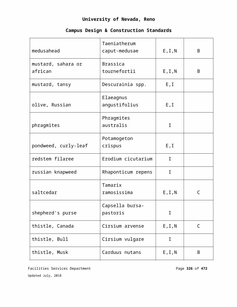
University of Nevada, Reno
Campus Design & Construction Standards
Details of typical trench cross sections showing conduit locations in the trench, clearances from final grade, backfill materials and depths, pavement cutting information, and compacting requirements for both paved and unpaved areas.
Construction notes applicable to the work being performed. A scale drawing showing location ties to existing structures, cable, conduit,
MH/HH’s, and any conflicting substructures. Profile drawings of congested areas where vertical and horizontal separation from other utilities is critical during cutting and placing operations.
A legend explaining industry standard drawing symbols of all relevant structures and work operations.
Conduit types, dimensions, and wall-to-wall measurements when used with MH/ HH, pedestals and Equipment and Telecommunications Rooms (ER/TR’s).
GROUNDING AND BONDING FOR COMMUNICATIONS SYSTEMS
BONDING AND SIZING THE TELECOMMUNICATIONS BONDING BACKBONE (TBB)The TBB shall be a copper conductor. The minimum TBB conductor size shall be a No. 6 AWG. The TBB should be sized at 2 kcmil per linear foot of conductor length up to a maximum size of 3/0 AWG. The TBB may be insulated. If the TBB is insulated, the insulation shall meet the fire ratings of its pathway. The sizing of the TBB is not intended to account for the reduction or control of electromagnetic interference. The TBB should be calculated for a size that conforms to the guidelines set by the NEC. Reference Table 1 Sizing of TBB.
TABLE 1 SIZING OF TBBTBB length linear m (ft.) TBB Size (AWG)
less than 4 (13) 6
4 – 6 (14 – 20) 4
6 – 8 (21 – 26) 3
8 – 10 (27 – 33) 2
10 – 13 (34 – 41) 1
Facilities Services Department Page 326 of 349
Updated July, 2018
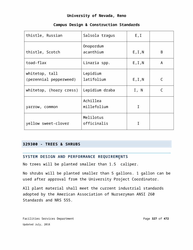
University of Nevada, Reno
Campus Design & Construction Standards
13 – 16 (42 – 52) 0
16 – 20 (53 – 66) 0
greater than 20 (66) 0
Bonding connections shall be made directly to the points being bonded, avoiding unnecessary connections or splices.
All grounding and bonding connectors shall be listed by a nationally recognized testing laboratory (NRTL) as required by the NEC.
The grounding or bonding conductor shall be connected to the grounding electrode by exothermic weld, listed lugs, listed pressure connectors, listed clamps, or other listed alternatives.
BONDING CONNECTIONSTypical connections are made using:
Bolts or crimps (e.g., connectors, clamps, or lugs) - Where possible, irreversible compression-type connections and two-hole lugs should be used. Laboratory-tested hardware should always be used.
Exothermic welding—A seamless molecular bond of metals is commonly applied to: Connections to, and within, the ac grounding electrode system. Locations requiring minimal maintenance. Parts of grounding systems that are subject to corrosion or that must reliably carry
high currents. All connections that are buried. Cable-to-lug connections. Bonds to structural steel.
All bonding connections should follow the manufacturer’s guidelines.
FIGURE 1 SMALL SYSTEMS (SINGLE ER/TR WITHIN A BUILDING)
Facilities Services Department Page 327 of 349
Updated July, 2018

University of Nevada, Reno
Campus Design & Construction Standards
NOTE: Small system installations must meet ANSI J/STD-607-A.
LARGE SYSTEMS (MULTIPLE ER/TR WITHIN A BUILDING)
Multiple Bus Bars are used where multiple ERs, TRs, and EFs exist in large buildings. Guidelines for this method are detailed in ANSI J/STD-607-A.
Each TMGB or TGB must have an effective bonding connection to the nearest approved building grounding electrode (e.g., structural steel) and the equipment grounding system (e.g., ac branch circuit panel board’s equipment grounding Bus Bar). See Figure 2 Recommended Large System Arrangement.
Facilities Services Department Page 328 of 349
Updated July, 2018

University of Nevada, Reno
Campus Design & Construction Standards
FIGURE 2 RECOMMENDED LARGE SYSTEM ARRANGEMENT (MULTIPLE ER/TR WITHI N A BUILDING)
ENTRANCE FACILITY (EF) TELECOMMUNICATIONS MAIN GROUNDING BUS BAR (TMGB)
The TMGB serves as the dedicated extension of the building ac grounding electrode system for the telecommunications infrastructure. It serves as the central attachment
Facilities Services Department Page 329 of 349
Updated July, 2018
University of Nevada, Reno
Campus Design & Construction Standards
point for the TBB and equipment. The TMGB must be a predrilled copper bus bar with holes for use with standard- sized lugs, have minimum dimensions of 6.3 mm (0.25 in) thick by 101 mm (4 in) wide, and be minimum 20” (see Figure 3). Furthermore, it must be listed by an NRTL.
FIGURE 3 TYPICAL TELECOMMUNICATIONS MAIN GROUNDING BUS BAR (TMGB)
It is recommended that the TMGB be located as near as possible to the cable EF to equalize surge currents due to lightning and other sources before they penetrate the infrastructure.
Placement the bus bar near the primary/secondary surge protection, cable sheaths, and entrance conduits.
A BCT is intended to bond the TMGB to the ac grounding electrode system via the ac main service entrance panel board. However, unless this bonding connection is made within 9 m (30 ftft.), this connection should not be specified since the impedance of this conductor, due to its length, may limit its effectiveness.
EQUIPMENT ROOM (ER)/ TELECOMMUNICATIONS ROOM (TR) TELECOMMUNICATIONS GROUNDING BUS BAR (TGB)
A TGB is the grounding connection point for telecommunications systems and equipment in the area served by an ER or TR. The TGB must be a predrilled copper Bus Bar with holes for use with standard-sized lugs, have minimum dimensions of 6.3
Facilities Services Department Page 330 of 349
Updated July, 2018

University of Nevada, Reno
Campus Design & Construction Standards
mm (0.25 in) thick by 51 mm (2 in) wide, and minimum length 10-inches (see Figure 4). It must also be listed by an NRTL.
FIGURE 4 TYPICAL TELECOMMUNICATIONS GROUNDING BUS BAR (TGB)
The TGB shall be bonded to the electrical panel serving the area where the TGB is installed, bonded to building steel and bonded in series to the main TMGB.
The ac grounding panel board, known as a branch circuit panel board, may reside in the ER. The TGB should also be bonded to the nearest structural steel member, whether it is a horizontal or vertical beam, if available.
RAISED FLOOR BONDING AND GROUNDING
If a raised floor is present, then the raised floor bonding system shall meet the requirements of the most current Nevada Electric Code.
One of the commonly overlooked grounding planes within an ER is a signal reference grid (SRG), often associated with raised flooring. An SRG may consist of copper straps taped to the concrete floor, a copper conductor alternately bonded to the different pedestals of the floor or it may be the floor itself with the stringers that support the tiles acting as the bonding conductor across the gradient of the floor. An SRG provides a low impedance path between many cabinets or racks of telecommunications equipment. Typical guidelines specify direct bonding to any conductive path that reaches the grid.
A bonding conductor must be run between the room’s associated grounding Bus Bar and to at least two points within the SRG if a raised floor is used within an ER, TR, or Facilities Services Department Page 331 of 349
Updated July, 2018
University of Nevada, Reno
Campus Design & Construction Standards
data processing center. This will ensure that an equipotential plane exists between the SRG and the grounding/ bonding infrastructure for the building.
ISOLATED GROUND (IG)
Isolated ground (IG) is an equipment grounding topology that reduces the effects of EMI and RFI on the equipment grounding system. IG-type receptacles can be identified with a continuous orange receptacle coloring or a beige receptacle coloring marked with an orange triangle on the face.
IMPORTANT: IG systems are not recommended for voice and data equipment, regardless of intent. Though such an equipment grounding system is permitted by the NEC® (e.g., provided it meets stringent wiring requirements), the use of such a system defeats the purpose of an equipotential plane that is desired for all EFs, equipment rooms (ERs), and TRs. Field trials of circuits that are constructed by the IG method indicate that using such a grounding system may expose equipment to more problems than could be encountered with a properly installed standard three-prong grounded receptacle.
LABELINGAll ground attachments shall be properly tagged and labeled in accordance with TIA/EIA-606-A.
Facilities Services Department Page 332 of 349
Updated July, 2018

University of Nevada, Reno
Campus Design & Construction Standards
FIGURE 5 TMGB/TGB BUS BAR LABELING
TESTING
Most qualified electrical installers do not test the grounding and bonding system for a building prior to its connection to the telecommunications grounding and bonding infrastructure.
However, BICSI recommends that certain tests be performed to evaluate the bonding connection between the telecommunications bus bars and the ac grounding electrode system. This testing should be performed after the cabling and grounding infrastructure are installed but prior to either the final approval of the cabling plant or end-use equipment installation.
As an alternative, the designer should specify that the TGB in each TR be bonded to the ac electrical panel board for that floor of the building with a supplemental bonding connection made to the metal frame of the building, where applicable. Each of the bonding connections should be tested to verify that a low resistance connection exists. Once one or both connections are achieved, the need for the TBB is eliminated.
The Telecommunications Ground & Bonding System shall be tested with an Earth Ground Resistance Tester used in the Two Point Test Method.
THE FOLLOWING WILL BE NEEDED TO TEST THE GROUNDING AND BONDING. CONTRACTOR SHALL SUPPLY TESTING EQUIPMENT.
An Earth Ground Resistance Tester with the attachments.
Facilities Services Department Page 333 of 349
Updated July, 2018
University of Nevada, Reno
Campus Design & Construction Standards
500-foot reel of #10 copper wire with ground clamps on both ends.
THE FOLLOWING IS THE PROCEDURE TO TEST THE GROUNDING & BONDING: All testing should be done with the entire building in operation. Nothing needs to be
shut down to test the grounding and bonding with this tester. Set up the meter in the two-point test mode. Zero the meter using the 500-foot number 10 copper test lead. Connect the short test lead from the meter to the close end of the wire/cable under
test. Connect the end of the 500-foot lead to the other end of the wire/cable under test. Take the reading of the wire/cable under test. If the ohm value is less than 0.1 Ohm between the two test points the bonding is
adequate.
TESTS TO BE CONDUCTED: The installer / technician conducting these tests must be certified level VI by UIC
ACCC TED. Test between the TMGB and the service equipment (power) ground. Test between the TMGB and each TGB in the system. Test between the TGB and:
Data racks. Cable tray. Telecommunication conduit. Caging. Electronic equipment.
These tests shall be conducted with the systems in operation.
These tests shall be recorded on sheets provided for this purpose by UNR.
CABLE TRAY FOR COMMUNICATIONS SYSTEMS CABLE TRAY FOR COMMUNICATIONS SYSTEMS
The use of a wire basket tray system is the preferred method of cable tray systems within the corridors. A minimum of 12-inches of clearance shall be provided above the cable tray and a minimum clearance of 12 to 18-inches on at least one side shall be provided for access to tray. Please refrain from specifying Two Side Rail (Metallic) Facilities Services Department Page 334 of 349
Updated July, 2018
University of Nevada, Reno
Campus Design & Construction Standards
Cable Tray Systems due to the limited amount of space in the ceiling areas. Minimum size is 12” wide x 4” high. Specify larger size to maintain 50% fill ratio.
Cablofil Basket Tray or equal
CONDUITS AND BACK BOXES FOR COMMUNICATIONS SYSTEMS
Each habitable space must be connected individually to the cable tray with two locations, at least one 1” conduit for Cat 6 projects and 1 ¼” for Cat 6A projects. In labs, or other multi-drop locations, each RJ-45 computer drop will have its own 1” or 1 ¼" conduit.
In general, conduit shall be zinc-coated, rigid steel conduit and shall meet in all respects, the UL Standards for Rigid Steel Conduit. The conduit shall be metalized, galvanized, or approved equal.
Electrical metallic tubing may be used in all locations unless otherwise noted. Electrical metal tubing shall be terminated with connectors with insulated throat. Metal lined terminating fittings will not be acceptable. All terminating fittings shall be secured to box or cabinet with double lock-nut type of construction. Couplings and connectors for electrical metallic tubing shall be steel and shall be of the compression type. Set screw and indentation type connectors will not be acceptable, except that approved type steel set screw connectors may be used on EMT 2- 1/2’ or larger. LB-type fittings are not permitted with communications cabling.
Runs of conduit or tubing shall have supports spaced in accordance with the NEC, and exposed conduit shall be installed with runs parallel or perpendicular to walls, structural members or intersections of vertical planes and ceilings, with right angle turns consisting of cast metal fittings or symmetrical bends. Bends or offsets shall be avoided where possible but where necessary shall be made with an approved conduit-bending machine. Conduit or tubing, which has been crushed or deformed in any way, shall not be installed. Expansion fittings or other approved devices shall be used to provide for expansion or contraction where conduit or tubing crosses expansion joints. Conduit and tubing shall be supported on an approved type of ceiling trapeze, beam clamps, strap hangers, or pipe straps, secured by means of toggle bolts on hollow masonry units, expansion shields in concrete or brick and machine screws on metal surfaces. The use of tie wire for suspending conduits or securing it to joists, purlins, beams, etc. will not be allowed. Conduit and tubing shall be installed in such a manner as to insure against trouble from the collection of trapped condensation, and all runs shall be arranged so as
Facilities Services Department Page 335 of 349
Updated July, 2018

University of Nevada, Reno
Campus Design & Construction Standards
toto be devoid of traps wherever possible. All necessary precautions to prevent the lodgment of dirt, plaster, or trash in conduit or tubing, fittings and boxes during construction shall be taken. A run of conduit or tubing, which has become clogged, shall be entirely freed of these accumulations or shall be replaced. Conduit shall be securely fastened to all sheet metal outlets, junction and pull boxes with double-galvanized lock nuts and insulating bushings.
All conduits shall be installed concealed unless otherwise noted or shown on the drawings. No conduit smaller than 1” shall be used. No flexible conduit shall be used unless specifically approved by the Engineer.
JUNCTION BOXESNo conduit run shall be more than 100 feet between access points. No conduit shall contain more than two 90-degree sweep bends between junction boxes. Junction boxes shall be no less than 18” x 18” x 12”.
All junction boxes used under this contract shall be constructed of code gauge, galvanized steel and shall be as manufactured by Steel City, Appleton, O0Z/Gedney, RACO, Killark, or approved equal.
CABLE ROUTINGThe following is a chart of minimum distances that UTP must be run from common sources of EMI (Electromagnetic interference):
EMI Source Minimum Distance
Fluorescent Lighting 12 inches
Neon Lighting 12 inches
Unshielded power cable 2 KVA or less 5 inches
Unshielded power cable over 2 KVA 39 inches
Transformers and Motors 39 inches
Facilities Services Department Page 336 of 349
Updated July, 2018
University of Nevada, Reno
Campus Design & Construction Standards
Whenever possible, avoid running UTP in locations where temperature will be below 40 degrees Fahrenheit or above 115 degrees Fahrenheit. Humidity should normally be in the range of 8- 80%.
All cable, conduit, and Wiremold (TM) routings shall utilize the path of least obstructions and shall be run parallel or perpendicular to existing walls. Hang multiple horizontal conduits in tight, vertically organized arrays and run vertical riser similarly. Avoid creating obstructions to future mechanical/electrical work.
All interior conduits required under this contract shall be provided with a non-conductive, fish tape, or approved nylon pull string.
FIRE RATED PENETRATIONSWherever conduit(s) pass through floor slabs in other than slab on grade construction, steel sleeves shall be provided for each conduit. Sleeves shall project 6” above and below slab and spaces between conduit and sleeves shall be fire stopped with material, which will provide a fire rating substantially the same as the un-pierced floor.
Penetrations through walls and ceilings, chases, shafts, or other architectural assemblies, for the passage of cable shall utilize STI EZPath or Ready Sleeve fire rated assemblies. The fire stop systems and products shall have been tested in accordance with the procedures of U.L and material shall be U.L. classified as material for use in through penetration fire stops.
Provide through penetration fire stopping systems to prevent the spread of fire through openings made in fire rated walls or floors to accommodate penetrating items such as conduit, cables and cable tray. Fire stop shall restore the floor and wall to the original fire integrity and shall be waterproof. The fire stop system shall comply with the NEC and NFPA 101- life safety code (latest edition) and shall be made available for inspection by local inspection authorities prior to cable system acceptance. The contractor shall be responsible for verifying the fire rating of all walls and floors having cabling penetration. When applicable, coordinate sealant installation with other trades and with general contractor on site.
End of Additional Communication / IT Requirements
Facilities Services Department Page 337 of 349
Updated July, 2018
University of Nevada, Reno
Campus Design & Construction Standards
APPENDIX L ELECTRICAL METHOD OF PROCEDUREThe following appendix includes information and standard drawingsthat are diagrammatic and are used only to convey intent.
ELECTRICAL METHOD OF PROCEDURE (MOP)
UNR requires a Method of Procedure (MOP) whenever there will be an electrical shutdown of our transmission and distribution system(s). The purpose of the MOP is:
Increase Safety. Minimize shut down time by planning properly. Coordinate duties between all parties involved in the shutdown process. Improve communication and provide a clear understanding of the process. Ensure proper PPE is used. Have communication between the University and any contractor working the
shut-down.
MOPS should include the following: Pre-work briefing with all that are present for the shutdown. Include safety discussion, all potential hazards. Job description – what will be done, when it will be done, the voltages and
location of the equipment will all need to be included. The steps that will be followed. Emergency procedures and collection points. Location of emergency exits. The levels of PPE required for each step. Include steps for pre-use inspection of PPE. Steps to take for Lock-out/Tag-out. Steps for verification of voltage / rotation or other tasks to be accomplished. How you will control access into the work area based on arc flash boundaries. Type of meter being used for voltage verification and max voltage rating. Lighting considerations.
THE FOLLOWING IS AN EXAMPLE OF AN ACTUAL MOP EXECUTED ON CAMPUS:MOP 7-23-2016
Ross Hall and Jones Center shut down.
Facilities Services Department Page 338 of 349
Updated July, 2018
University of Nevada, Reno
Campus Design & Construction Standards
Work to be performed: UNR to replace wire to main switch gear for new water heater, tighten and clean gear and panels in Ross Hall and Jones Center.
Contractor Contact - John Doe – 775-321-1234
UNR Contact – Project Coordinator – 775-987-6789
Proper PPE Category 2 and 4 / 8 cal. and 40 cal. Fluke volt meter Lock out tag out, lock out tag out treeEquipment LED lights Socket sets Rags 5-point sockets Torque Wrenches Portable Generators Cords Vacuums Torque specs. Hot Sticks Rope with a hook
Morning meeting at 6:30 am in Electric shop Saturday 7-23-2016 Review Project with UNR MOP Verify Rotation at 120/208 volt disconnect on main transformer with Category 2/8
cal2 gear (James and Steve).Power shut down 7:00 am with Joe from Contractor X on site in case switch does not work
UNR Open Main breakers in Ross and Jones and LOTO (Steve and James). UNR open PB- 13, open, close, open 4160-volt switch to Ross and Jones with
Category 4/40 cal2 gear (Steve and James). Close vault lid, LOTO PB-13. UNR Verify power is de-energized to Ross and Jones with Category 2/8 cal2 gear
(Steve and James). If PB- 13 switches correctly, Joe from Contractor X can leave.
7:00 to 3:00 pm. UNR to pull wire for water heater @ Ross Hall (Brent and Cimothy). UNR torque and cleaning switch gear @ Ross Hall (Brent and Cimothy). Check all Emergency lights in Ross and Jones (James, Steve).
Facilities Services Department Page 339 of 349
Updated July, 2018
University of Nevada, Reno
Campus Design & Construction Standards
UNR to torque and clean panels @ Ross Hall and Jones (James, Steve, Brent, and Cimothy).
UNR clean and torque transformer (not the porcelain bushings) T- RHJV. UNR exercise all breakers in both buildings. Make drawing of conduits in PB-13 for FS Electrical Engineer.
Re-energize power 3:30 pm or sooner UNR contact control shop (997-9652) before we re-energize UNR remove LOTO from PB-13 UNR close switch at PB-13 with Category 4/40 cal2 gear (James and Steve) UNR Verify three phase power Ross and Jones with Category 2/8 cal2 gear
(James and Steve). UNR close Main breakers @ Ross and Jones with Category 2/8 cal2 gear (James
and Steve). UNR confirms power is restored to both buildings. Clean up and put away all tools and equipment.
If Switch fails Joe from Contractor X is on standby to bypass switch.Joe (775) 555-1234
END OF ELECTRICAL METHOD OF PROCEDURE
Facilities Services Department Page 340 of 349
Updated July, 2018
University of Nevada, Reno
Campus Design & Construction Standards
BASIC SYSTEMS REQUIRING THIRD PARTY COMMISSIONING
HVAC
HOT WATER, GLYCOL, CHILLED WATER, AND CONDENSER WATER PIPING SYSTEMS Work includes installation inspections and checks; pressure tests and documentation; expansion tanks; confirmation of flow balancing completion; seismic restraints installation certification.
DUCT AND AIR-HANDLING SYSTEMSWork includes installation inspections and checks; confirmation of flow balancing completion; leak testing as applicable; seismic restraints installation certification.
CHILLERSWork includes installation inspections and checks; seismic restraints installation certification; checkout and startup by manufacturer’s representative; documented performance measurements including capacity, evaporator and condenser flows, motor amperage, controls operation, and sound levels.
COOLING TOWERS Work includes installation inspection and checks; seismic restraints installation certification; chemical treatment; checkout and startup by manufacturer’s representative in conjunction with chiller; documented performance measurements including sound, capacity, motor amperage, pan heater operation, sweeper system operation, makeup water, overflow, and capacity controls.
CLOSED-CIRCUIT HEAT REJECTORS OR EVAPORATIVE CONDENSERWork includes installation inspection and checks; seismic restraints installation certification; chemical treatment; checkout and startup by manufacturer’s representative in conjunction with chiller; documented performance measurements including sound,
Facilities Services Department Page 341 of 349
Updated July, 2018
University of Nevada, Reno
Campus Design & Construction Standards
capacity, motor amperage, pan heater operation, sweeper system operation, makeup water, overflow, and capacity controls.
REFRIGERATION COMPRESSOR/CONDENSING UNITWork includes installation inspection and checks; seismic restraints installation certification; checkout and startup by manufacturer’s representative as specified; documented performance measurements including capacity, evaporator and condenser pressures, motor current draw, and controls operation.
BOILERS Work includes installation inspection and checks; seismic restraints installation certification; boil out and chemical treatment; checkout and startup by manufacturer’s representative as specified; documented performance measurements including combustion efficiency, capacity test, burner and controls operation.
PUMPS Work includes documented checks on alignment, rotation, motor current draw, flows and pressures.
SUPPLY, RETURN, RELIEF AND EXHAUST FANS Work includes checks on installation; seismic restraints; dampers and other accessories; rotation, sound levels, motor current draw, and airflows and pressures.
AIR HANDLING UNITS (BOTH PACKAGED AND BUILT-UP) Work includes installation inspections and checks; seismic restraints installation certification; checkout and startup by manufacturer’s representative as specified; documented capacity tests, for heating, cooling, air flow and static pressures; operation of all controls; sound level.
AIR TERMINAL DEVICES Work includes installation inspection and checks; for VAV units, flow adjustments and calibration coordinated with controls and air balancing; controls operation including flow modulation, reheat, controls responses.
Facilities Services Department Page 342 of 349
Updated July, 2018
University of Nevada, Reno
Campus Design & Construction Standards
FAN-COIL UNITS Work includes installation inspections and checks; performance and controls checks.
WATER-SOURCE HEAT PUMPS
Work includes installation inspections and checks; documented seismic installation certification; performance and controls checks.
CONTROLS AIR COMPRESSOR Work includes installation inspections and checks; documented seismic installation certification; operational checks.
DIRECT DIGITAL CONTROL SYSTEM Work includes inspections and checks of installation and operation of all devices; complete operation of all controls sequences, in coordination with commissioning of all controlled systems.
VARIABLE FREQUENCY DRIVES/MOTOR CONTROLS Work includes inspections and checks of installation and operation of all devices; complete operation of all controls sequences, in coordination with commissioning of all controlled systems.
ELECTRICAL COMMISSIONING
PAD MOUNT SWITCHWork includes visual inspections of the equipment, anchoring, paint, labeling, clearances, grounding, terminations, testing caps, bleeder wires, cable supports, conductor phasing, vault cleanliness, vault and door hardware. Review of cable testing report for each conductor. Review and record settings of overcurrent protection. Test tripping mechanisms for each fault interrupter. Verify and record gas levels. Verify arc flash labeling is installed and in agreement with arc flash study.
PAD MOUNT TRANSFORMERWork includes visual inspections of the equipment, anchoring, paint, labeling, clearances, grounding, torqueing of terminations, conductor phasing, cleanliness, door
Facilities Services Department Page 343 of 349
Updated July, 2018

University of Nevada, Reno
Campus Design & Construction Standards
hardware, and door seals. Review cable testing report for each conductor. Verify gauges are working properly and record gauge readings. Verify arc flash labeling is installed and in agreement with arc flash study.
MAIN SWITCHBOARDWork includes visual inspections of the equipment, anchoring, paint, labeling, nameplate information, clearances, grounding, torqueing of terminations, conductor phasing, cleanliness, door hardware, and door seals. Review cable testing report for each conductor. Record all circuit breaker settings and verify that each setting is in accordance with the coordination study. Verify arc flash labeling is installed and in agreement with arc flash study. Test and verify the accuracy of the load meter in each function and verify values can be seen on the campus control system. Test and verify the operation of the shunt trip mechanism. Inspect installation and functions of the surge suppression device and verify SPD lead lengths are as short as possible.
DISTRIBUTION BOARDSWork includes visual inspections of the equipment, anchoring, paint, labeling, nameplate information, clearances, grounding, torqueing of terminations, conductor phasing, cleanliness, door hardware, and door seals. Review cable testing report for each conductor. Record all circuit breaker settings and verify that each setting is in accordance with the coordination study. Verify arc flash labeling is installed and in agreement with arc flash study. Inspect installation and functions of the surge suppression device and verify SPD lead lengths are as short as possible.
STEP DOWN TRANSFORMERSWork includes visual inspections of the equipment, anchoring, paint, labeling, nameplate information, clearances, grounding, torqueing of terminations, conductor phasing, vibration isolation, and cleanliness. Review cable testing report for each conductor. Verify arc flash labeling is installed and in agreement with arc flash study.
BRANCH CIRCUIT PANELSWork includes visual inspections of the equipment, anchoring, paint, labeling, nameplate information, clearances, grounding, torqueing of terminations, conductor phasing, cleanliness, and door hardware. Review cable testing report for each feeder conductor. Record main circuit breaker settings and verify that each setting is in
Facilities Services Department Page 344 of 349
Updated July, 2018

University of Nevada, Reno
Campus Design & Construction Standards
accordance with the coordination study. Verify arc flash labeling is installed and in agreement with arc flash study.
LIGHTING CONTROL/TIME CLOCKS/PHOTOCELLSWork includes a visual inspection of the equipment, anchoring, paint, labeling, nameplate information, clearances, grounding, terminations and cleanliness. Test each device for on/off operation by local and remote control by DDC system. Verify and record timed on/off settings. Test all motion sensors and dual level switching in each room. Test on/off function of all exterior lighting and verify time settings. Verify each lighting fixture is working properly. Perform a 90-minute run test of all emergency lighting with the building power off. Verify all emergency lighting fixtures both interior and exterior are providing required lighting levels at 90 minutes.
GENERATORWork includes visual inspection of the equipment, anchoring, paint, labeling, nameplate information, clearances, grounding, termination, no leaks, gauges, battery charger, battery heater, block heater, meters, control panel, weatherproof/sound attenuated enclosure, bird screens, and cleanliness. With permanently installed or portable load bank perform and record a full load 3 hour run test. Test and record the function of the following items: gauges, battery charger, battery heater, block heater, emergency stop switch, meter, control panel functions, fuel level alarm, oil pressure alarm, coolant level alarm, high temperature alarm. With the generator running record sound levels in multiple directions and at multiple distances. Verify arc flash labeling is installed and in agreement with arc flash study. Test and verify that the function of the shunt trip device. Verify fuel tank is full after all tests.
AUTOMATIC TRANSFER SWITCHTest and record all functions are operational. Perform a loss of power test to the building and verify all functions work properly. Test and verify all by-pass functions. Verify and record frequency and duration of generator exercising. Verify arc flash labeling is installed and in agreement with arc flash study.
UPS SYSTEMWork includes visual inspection of the equipment, anchoring, paint, labeling, nameplate information, clearances, grounding, terminations, control panel, batteries, wiring, and
Facilities Services Department Page 345 of 349
Updated July, 2018

University of Nevada, Reno
Campus Design & Construction Standards
cleanliness. With batteries fully charged perform a full load run test. Record voltage and current levels every minute during the test for the duration of the specified run time. Verify closed transition switching during a loss of power and restoration of power to the building. Test and verify all alarms. Test and verify by-pass functions. Verify arc flash labeling is installed and in agreement with arc flash study.
FIRE ALARM SYSTEMWork includes visual inspection of the equipment, anchoring, paint, nameplate information, batteries, wiring, grounding, terminations, device installations and locations. Test all functions of the system. Verify the function and address of each initiating and indicating device for supervisory, trouble and alarm signals. Test and verify interface with HVAC equipment and controls. Perform a loss of power test. Verify required certifications and proper tagging. Perform all tests in the presence of the Authority Having Jurisdiction. Test the auto-dialer for functionality. Verify all supervisory, trouble and alarm signals are cleared upon completion.
END OF BASIC SYSTEM REQUIRING COMMISSIONING
Facilities Services Department Page 346 of 349
Updated July, 2018

University of Nevada, Reno
Campus Design & Construction Standards
SCOPE OF SERVICES, THIRD PARTY COMMISSIONING AGENT
DESIGN PHASEReview design documents (drawings and specifications) and provide comments and suggestions for designer consideration
100% Schematic Design 100% Design Development 50% Construction Documents 100% Construction Documents
COMMISSIONINGPrepare a commissioning plan to be included in the bid documents
Scope of commissioningo Describe the overall commissioning process.
The commissioning teamo List all members of the commissioning team, identified by individual name
and corporate identity (if known) or by functional identity (e.g. general contractor, mechanical contractor, etc.) and describe their roles and responsibilities.
Reference documents o Drawings, specifications, and published standards or guidelines relevant
to commissioning requirements. Commissioning meeting requirements
o Describe the purpose and number of commissioning meetings.
SYSTEM-SPECIFIC DETAILS For each system to be commissioned, the commissioning plan will include the details listed below.
The plan should also identify the required testing sequence, progressing logically from equipment, to sub-systems, from systems, to interactions between systems.
Facilities Services Department Page 347 of 349
Updated July, 2018
University of Nevada, Reno
Campus Design & Construction Standards
Equipment readiness – Describe the system verification checks to be carried out prior to start-up, and include specific checklists.
Equipment and system start-ups – Describe the step-by-step start-up procedure for each system and piece of equipment. If the specification requires that the manufacturer’s authorized technician perform the start-up, then the plan should require that a copy of the completed and signed manufacturer start-up form be included with the start-up checklist in the final documentation.
Functional performance tests – Detail the tests needed to be demonstrated by the contractor and witnessed by the commissioning team for the correct operation under all modes of operation, and include the applicable pass/fail criteria.
Acceptance – List the criteria for completion of the commissioning process. Typically, these will include verification of functional performance for all systems, submission of test and balance reports, operation and maintenance manuals, as well as other project specific criteria.
Operation and maintenance staff orientation and training – Describe the intended program for staff orientation, training and demonstration. Training sessions will be videotaped.
DOCUMENTATION REQUIREMENTSlist all documentation required for the final commissioning report. The commissioning plan itself will form the basis of this documentation, which will typically include:
A document reference list Descriptions of each system, including sequence of operation Completed and signed system verification, start-up and functional performance
test checklists Retests of all unacceptable results Training documentation, including an agenda for each scheduled session, a list
of attendees, and videotape requirements Comprehensive operations and maintenance data Estimated Schedule
CONSTRUCTION PHASE
Facilities Services Department Page 348 of 349
Updated July, 2018
University of Nevada, Reno
Campus Design & Construction Standards
Organize and lead the commissioning team. Review shop drawings and equipment submittals for information affecting the
commissioning process. Update the commissioning plan to reflect equipment and controls data from the
submittals, and provide commissioning schedule information that the contractor can integrate into the project schedule.
Schedule and lead commissioning meetings. Establish and maintain a system for tracking issues needing resolution. Review the project schedule periodically to ensure commissioning activities are
properly incorporated; provide feedback to the designer as needed. Perform on-site observations during construction. Monitor correct component and equipment installation; including controls point-
to-point checkouts. Document all observations. Witness equipment and system start-ups as deemed necessary. Ensure
complete documentation. Other related work.
ACCEPTANCE PHASE
Review and inspect, on a sample basis, the testing, adjusting and balancing work that has been carried out by another agency.
Contractor to conduct all functional performance tests as written by the commissioning team. All functional performance tests shall be witnessed and documented by the commissioning team of sub-systems, systems, and interactions between systems. Retesting shall be scheduled for all failed tests until all functional performance tests pass the prescribed acceptance level.
Organize and direct the training of O&M personnel. Videotape O&M training sessions.
POST-ACCEPTANCE PHASE
Conduct functional performance testing of sub-systems, systems, and interactions between systems that could not be carried out prior to acceptance due to unsuitable weather conditions.
Prepare and submit a final commissioning report. Provide follow-up for quality performance during the guarantee period.
Facilities Services Department Page 349 of 349
Updated July, 2018


![3 Trial/gle Trll.'ses Frame COIll]Jln • . page 6 Trial/gle Trll.'ses Frame COIll]Jln •..... . page 6 MODERN STEEL CONSTRUCTION Published by American Institute of Steel Construction](https://static.fdocuments.net/doc/165x107/5d178feb88c99309378df574/3-trialgle-trllses-frame-coilljln-page-6-trialgle-trllses-frame-coilljln.jpg)