Secondary Stage Creep Deformations and Stresses in Thick ... · Thick Spherical Vessels Considering...
12
© 2018 JETIR April 2018, Volume 5, Issue 4 www.jetir.org (ISSN-2349-5162) JETIR1804365 Journal of Emerging Technologies and Innovative Research (JETIR) www.jetir.org 834 Secondary Stage Creep Deformations and Stresses in Thick Spherical Vessels Considering Plain Strain Sukhjinder Singh Sandhu a , Tejeet Singh b and V.K.Gupta c a Assistant Professor, Department of Mechanical Engg, S. B. S. S. T. C., Ferozepur, 152004, INDIA b Associate Professor, Department of Mechanical Engg, S. B. S. S. T. C., Ferozepur, 152004, INDIA c Professor, Mech. Engg., UCoE, Punjabi Univ., Patiala-147002, INDIA Abstract The secondary stage creep deformations and creep stress in a thick walled spherical vessels made of functionally graded composites has been obtained in the present study. The spherical pressure vessel chosen for the investigation is subjected to internal and external pressure under constant temperature field. The material of the vessel is incompressible and volume constancy condition was assumed. The creep behaviour of material is governed by threshold stress based creep law. The study reveals that for linear variation of reinforcement and assumed pressure ratio the compressive value of radial stress reduces with increase in pressure ratio from 2 to 5 over entire radial distance. However, the longitudinal stress remains compressive at inner radius, however, the value become tensile for pressure ratio 3, 4 and 5. Key words: Spherical Vessel; Secondary Creep; Functionally Graded Material; Axial Stress. 1. Introduction The use of functionally graded materials for applications such as spherical pressure vessels subjected to high pressure and temperature is an important area of investigation (Sultana and Mondal, 2012). It is seen that many application involving spherical pressure vessels are subjected to high temperatures for long duration and therefore material of the vessel undergoes creep stresses and thereby reducing its service life. Most of the components used under high pressure and temperature are designed for minimum strain rate in the secondary stage creep during their lifetime. Therefore, study of secondary stage creep is very important from structural design point of view. In applications like power plants and petrochemical industry the spherical vessels are also subjected to a radial thermal gradient of the
Transcript of Secondary Stage Creep Deformations and Stresses in Thick ... · Thick Spherical Vessels Considering...
© 2018 JETIR April 2018, Volume 5, Issue 4 www.jetir.org (ISSN-2349-5162)
JETIR1804365 Journal of Emerging Technologies and Innovative Research (JETIR) www.jetir.org 834
Secondary Stage Creep Deformations and Stresses in
Thick Spherical Vessels Considering Plain Strain
Sukhjinder Singh Sandhua, Tejeet Singhb and V.K.Guptac a Assistant Professor, Department of Mechanical Engg, S. B. S. S. T. C., Ferozepur, 152004, INDIA
b Associate Professor, Department of Mechanical Engg, S. B. S. S. T. C., Ferozepur, 152004, INDIA
c Professor, Mech. Engg., UCoE, Punjabi Univ., Patiala-147002, INDIA
Abstract
The secondary stage creep deformations and creep stress in a thick walled spherical vessels made of functionally
graded composites has been obtained in the present study. The spherical pressure vessel chosen for the investigation
is subjected to internal and external pressure under constant temperature field. The material of the vessel is
incompressible and volume constancy condition was assumed. The creep behaviour of material is governed by
threshold stress based creep law. The study reveals that for linear variation of reinforcement and assumed pressure
ratio the compressive value of radial stress reduces with increase in pressure ratio from 2 to 5 over entire radial
distance. However, the longitudinal stress remains compressive at inner radius, however, the value become tensile
for pressure ratio 3, 4 and 5.
Key words: Spherical Vessel; Secondary Creep; Functionally Graded Material; Axial Stress.
1. Introduction
The use of functionally graded materials for applications such as spherical pressure vessels subjected to high pressure
and temperature is an important area of investigation (Sultana and Mondal, 2012). It is seen that many application
involving spherical pressure vessels are subjected to high temperatures for long duration and therefore material of
the vessel undergoes creep stresses and thereby reducing its service life. Most of the components used under high
pressure and temperature are designed for minimum strain rate in the secondary stage creep during their lifetime.
Therefore, study of secondary stage creep is very important from structural design point of view. In applications like
power plants and petrochemical industry the spherical vessels are also subjected to a radial thermal gradient of the
© 2018 JETIR April 2018, Volume 5, Issue 4 www.jetir.org (ISSN-2349-5162)
JETIR1804365 Journal of Emerging Technologies and Innovative Research (JETIR) www.jetir.org 835
order of 50°C along with pressure (Johnson and Khan, 1963; Sim, 1973; Durban and Baruch, 1974). Therefore, it
requires a different analysis as compared to the vessels exposed to constant temperature conditions.
The general theory of creep in pressure vessels was developed by Bhatnagar and Arya (1973) and applied to the
solution of a specific problem using Norton’s creep law. Steady-state creep analysis of thick-walled spherical
pressure vessels with varying creep properties has been presented by You and Ou (2008). Stresses in a spherical
pressure vessels undergoing creep and dimensional changes has been presented by Miller (1995). Analytical and
numerical analysis for the Functionally Graded thick sphere under combined pressure and temperature loading has
been presented by Bayat et al (2012). In all these studies the strains are assumed to be infinitesimal and the
deformation is referred with respect to original dimensions of the sphere.
The excellent properties of metal matrix composites (MMCs) like high specific strength and stiffness, and high
temperature stability make them suitable choice for applications involving high pressure and temperature (Harris,
1999). Therefore, it was decided to investigate the secondary creep in a sphere made of Al- SiC composite and
subjected to internal and external pressure and exposed to uniform temperature field. A mathematical model has
been developed to describe the secondary stage creep behavior of the functionally graded sphere. The model
developed is used to investigate the effect of different pressure ratios on the steady state creep in a thick-walled
functionally graded spherical vessel.
The content of silicon carbide in Al matrix has been assumed to vary linearly, with maximum amount at the inner
radius and minimum at the outer radius of spherical vessel. A mathematical model has been developed and used to
analyze the effect of varying the radial distribution of SiC on the steady state creep response of sphere.
2. Creep Analysis and Mathematical Solution
For aluminium matrix composites undergoing secondary stage creep, the relation between effective strain rate ( e )
and effective stress (e) can be described by the well-known threshold stress (o) based creep law (Singh and Gupta,
2011) and is given by,
𝜀�̇� = {𝑀(𝑟)(𝜎𝑒 − 𝜎0(𝑟))}𝑛
(1)
© 2018 JETIR April 2018, Volume 5, Issue 4 www.jetir.org (ISSN-2349-5162)
JETIR1804365 Journal of Emerging Technologies and Innovative Research (JETIR) www.jetir.org 836
In the present study, the values of M and σ0 have been obtained from following regression equations developed from
experimental data of Pandey et al (1992). The developed regression equations are given below,
𝑀(𝑟) = 0.0287611 −0.00879
𝑃−
14.02666
𝑇−
0.032236
𝑉(𝑟) (2)
𝜎𝑜(𝑟) = −0.084𝑃 − 0.0232𝑇 + 1.1853(𝑉(𝑟)) + 22.207 (3)
Where P, V(r), T, M(r) and o(r) are respectively the particle size, particle content, temperature, creep parameter and
threshold stress at any radius (r) of the FGM spherical pressure vessels. In the present work particle size is assumed
as 1.7 μm while operating temperature is kept as 623K. The reinforcement content i.e. silicon carbide particle (SiCp),
in the sphere is assumed to vary linearly from the inner radius (a) to the outer radius (b). As a result, creep parameters
will vary with the radius. The variation of SiCp is described by following equation (Singh and Gupta, 2011)
Particle content 𝑉(𝑟) = 𝑉𝑚𝑎𝑥 −(𝑟−𝑎)
(𝑏−𝑎)(𝑉𝑚𝑎𝑥 − 𝑉𝑚𝑖𝑛) (4)
Where, Vmax and Vmin are respectively the maximum and minimum SiCp, at the inner and outer radii.
The average particle content (Vavg) in spherical vessel can be expressed as,
𝑉𝑎𝑣𝑔 =∫ 2𝜋𝑟𝑙.𝑉(𝑟)𝑑𝑟
𝑏𝑎
𝜋(𝑏2−𝑎2)𝑙 (5)
Substituting the value of particle content, V(r), from Eqn. (4) into Eqn. (5) and integrating the resulting equation, we
get,
𝑉𝑚𝑖𝑛 =3𝑉𝑎𝑣𝑔(1−²)(1−)−𝑉𝑚𝑎𝑥(1−3²+23)
(2−3+3) (6)
Where, is the ratio of inner to outer radius (i.e. a/b) of spherical vessel.
Thus for a given FG sphere containing particle gradient both the creep parameters will be function of radius. The
value of M(r) and σo (r) at any radius could be estimated by substituting the reinforcement content V(r) from equation
(4) in into equation (2) and (3).
Let us consider a thick-walled, spherical vessel made of functionally graded Al-SiCp composite. The vessel is
assumed to have inner and outer radii as a and b respectively and is subjected to both internal pressure p and external
pressure q.
The geometric relationships between radial and circumferential strain rates and radial displacement rate are
© 2018 JETIR April 2018, Volume 5, Issue 4 www.jetir.org (ISSN-2349-5162)
JETIR1804365 Journal of Emerging Technologies and Innovative Research (JETIR) www.jetir.org 837
𝜀�̇� =𝑑�̇�𝑟
𝑑𝑟 (7)
𝜀�̇� =�̇�𝑟
𝑟 (8)
Where, �̇�𝑟 and 𝜀�̇� are respectively radial and circumferential strain rates, �̇�𝑟 (=𝑑𝑥
𝑑𝑡) is the radial displacement rate
and 𝑥 is the radial displacement.
Eliminating 𝑥�̇�, from Eqns. (7) and (8) the deformation compatibility equation is obtained as,
𝑟𝑑�̇�𝜃
𝑑𝑟= (𝜀�̇� − 𝜀�̇�) (9)
Considering the equilibrium of forces on an element of spherical vessel along the radial direction, we get the
equilibrium equation as below,
𝑟
2
𝑑𝜎𝑟
𝑑𝑟= (𝜎𝑧 − 𝜎𝑟) (10)
Where, 𝜎𝜃 and 𝜎𝑟 are respectively the circumferential and radial stresses.
Since the material of the sphere is assumed to be incompressible, therefore,
𝜀�̇� + 𝜀�̇� + 𝜀�̇� = 0 (11)
Where, 𝜀�̇� is the axial strain rate.
The steady state creep deformations in thick-walled spherical pressure vessels are spherically symmetric i.e. 𝜎𝜃 =
𝜎𝑧, thus the constitutive equations (Singh and Gupta, 2011) for creep along the principal direction r, and z can be
written as below,
𝜀�̇� =�̇�𝑒
𝜎𝑒(𝜎𝑟 − 𝜎𝜃) (12)
𝜀�̇� =�̇�𝑒
2𝜎𝑒(𝜎𝑧 − 𝜎𝑟) (13)
Where 𝜀�̇� is the effective strain rate, 𝜎𝑒 is the effective stress respectively.
From Eqs. (12) and (13), the relationship between the radial and axial strain rates can be obtained as,
𝜀�̇� = −2𝜀�̇� (14)
Substituting Eqn. (14), into Eqn. (9), the deformation compatibility becomes,
© 2018 JETIR April 2018, Volume 5, Issue 4 www.jetir.org (ISSN-2349-5162)
JETIR1804365 Journal of Emerging Technologies and Innovative Research (JETIR) www.jetir.org 838
𝑑�̇�𝑧
�̇�𝑧= −3
𝑑𝑟
𝑟 (15)
The integration of Eqn. (15), gives the axial strain rate as,
𝜀�̇� =𝐴1
𝑟3 (16)
Where, A1 is constant of Integration.
The effective stress in thick-walled spherical vessels subjected to internal pressure is assumed to be expressed by
von-Mises equation (Singh and Gupta, 2011),
𝜎𝑒 = (𝜎𝑧 − 𝜎𝑟) (17)
Using Eqn. (17) into Eqn. (13), we get,
𝜀�̇� = 2𝜀�̇� =2𝐴1
𝑟3 (18)
Using Eqn. (4) into above Eqn. (18), we get,
𝜎𝑒 =(2𝐴1)
1𝑛
𝑟3/𝑛𝑀(𝑟)+ 𝜎𝑜(𝑟) (19)
Using Eqn. (17) into above Eqn. (19), we get,
𝜎𝑧 − 𝜎𝑟 =𝐴2(𝑟)
𝑟3𝑛
+ 𝜎𝑜(𝑟) (20)
Where 𝐴2(𝑟) = [(2𝐴1)
1𝑛
𝑀(𝑟)]
Substituting equilibrium Eqn. (10) into above equation and integrating the resulting equation between limits a to r,
we get,
𝜎𝑟 = 2 ∫𝐴2(𝑟)
𝑟(𝑛+3)
𝑛
𝑑𝑟𝑟
𝑎+ 2 ∫
𝜎𝑜(𝑟)
𝑟𝑑𝑟
𝑟
𝑎+ 𝐴3 (21)
Where, A3 is constant of integration.
The following boundary conditions are assumed for the spherical vessel,
(i). 𝑎𝑡 𝑟 = 𝑎, 𝜎𝑟 = −𝑝 (22)
(ii). 𝑎𝑡 𝑟 = 𝑏, 𝜎𝑟 = −𝑞 (23)
© 2018 JETIR April 2018, Volume 5, Issue 4 www.jetir.org (ISSN-2349-5162)
JETIR1804365 Journal of Emerging Technologies and Innovative Research (JETIR) www.jetir.org 839
Eqn. (21) may be solved between limits a and b and under the enforced boundary conditions given in Eqs. (22) and
(23) to get the value of ‘A1’ as
𝐴1 =1
2[
𝑝−𝑞−2𝐴4
2𝐴5]
𝑛
(24)
Where 𝐴4 = ∫𝜎0(𝑟)
𝑟𝑑𝑟
𝑏
𝑎and 𝐴5 = ∫
1
𝑟(𝑛+3) 𝑛⁄ 𝑀(𝑟)𝑑𝑟
𝑏
𝑎
Applying boundary conditions in Eqn. (21), the radial stress is obtained as,
𝜎𝑟 = 2 ∫𝐴2(𝑟)
𝑟(𝑛+3)
𝑛
𝑑𝑟𝑟
𝑎+ 2 ∫
𝜎𝑜(𝑟)
𝑟𝑑𝑟
𝑟
𝑎− 𝑝 (25)
A computer program has been developed to calculate the steady state creep response of the FG spherical vessel for
various combinations of size and content of the reinforcement, and operating temperature. For the purpose of
numerical computation, the inner and outer radii of the spherical vessel are taken 500 mm and 800 mm respectively,
and the internal pressure is assumed to be 100 MPa and external pressure varies as 50 MPa, 33.33 MPa, 25 MPa
and 20 MPa so that ratio of p/q = 2, 3, 4 and 5. The radial stress at different radial locations of the sphere is calculated
respectively from Eqs. (25). The creep parameters M(r) and o (r), required during the computation process, are
estimated respectively from Eqs. (2) and (3).
3. Results and Discussions
On the basis of mathematical analysis, numerical calculations have been carried out to obtain the secondary stage
creep behaviour of functionally graded spherical pressure vessels. The results have been obtained for different
pressure ratios in FG spheres. The internal pressure is taken as 100 MPa, however external pressure is varied to
obtain pressure ratio as 2, 3, 4 and 5.
3.1 : Variation of Particle Content and Creep Parameters.
The distribution of SiC particles in spherical vessel is linear with maximum particle content is 30 vol% at inner
radius. The content of reinforcement is assumed to decrease linearly along the radial distance. The average particle
content is kept as 20 vol%.
© 2018 JETIR April 2018, Volume 5, Issue 4 www.jetir.org (ISSN-2349-5162)
JETIR1804365 Journal of Emerging Technologies and Innovative Research (JETIR) www.jetir.org 840
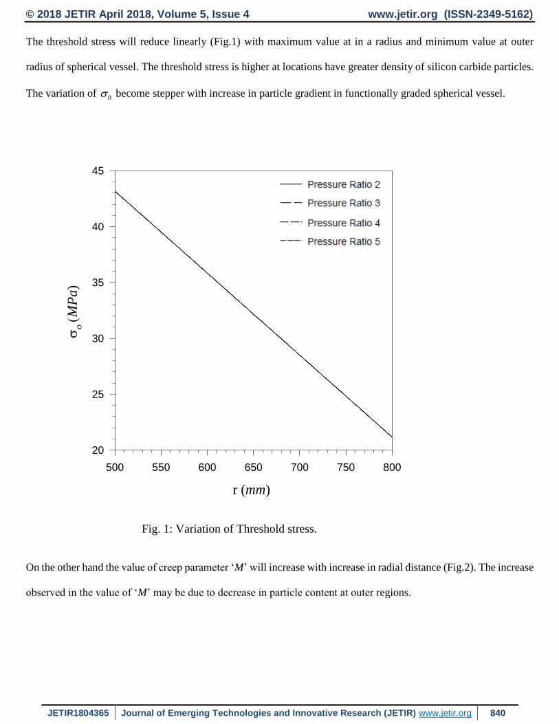
The threshold stress will reduce linearly (Fig.1) with maximum value at in a radius and minimum value at outer
radius of spherical vessel. The threshold stress is higher at locations have greater density of silicon carbide particles.
The variation of 0 become stepper with increase in particle gradient in functionally graded spherical vessel.
r (mm)
500 550 600 650 700 750 800
M
Pa
)
20
25
30
35
40
45
Fig. 1: Variation of Threshold stress.
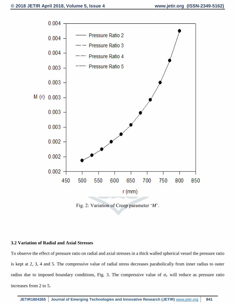
On the other hand the value of creep parameter ‘M’ will increase with increase in radial distance (Fig.2). The increase
observed in the value of ‘M’ may be due to decrease in particle content at outer regions.
© 2018 JETIR April 2018, Volume 5, Issue 4 www.jetir.org (ISSN-2349-5162)
JETIR1804365 Journal of Emerging Technologies and Innovative Research (JETIR) www.jetir.org 841
Fig. 2: Variation of Creep parameter ‘M’.
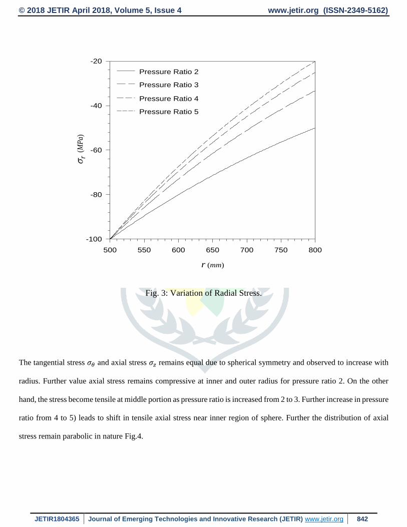
3.2 Variation of Radial and Axial Stresses
To observe the effect of pressure ratio on radial and axial stresses in a thick walled spherical vessel the pressure ratio
is kept at 2, 3, 4 and 5. The compressive value of radial stress decreases parabolically from inner radius to outer
radius due to imposed boundary conditions, Fig. 3. The compressive value of 𝜎𝑟 will reduce as pressure ratio
increases from 2 to 5.
© 2018 JETIR April 2018, Volume 5, Issue 4 www.jetir.org (ISSN-2349-5162)
JETIR1804365 Journal of Emerging Technologies and Innovative Research (JETIR) www.jetir.org 842
r (mm)
500 550 600 650 700 750 800
r
(M
Pa)
-100
-80
-60
-40
-20
Pressure Ratio 2
Pressure Ratio 3
Pressure Ratio 4
Pressure Ratio 5
Fig. 3: Variation of Radial Stress.
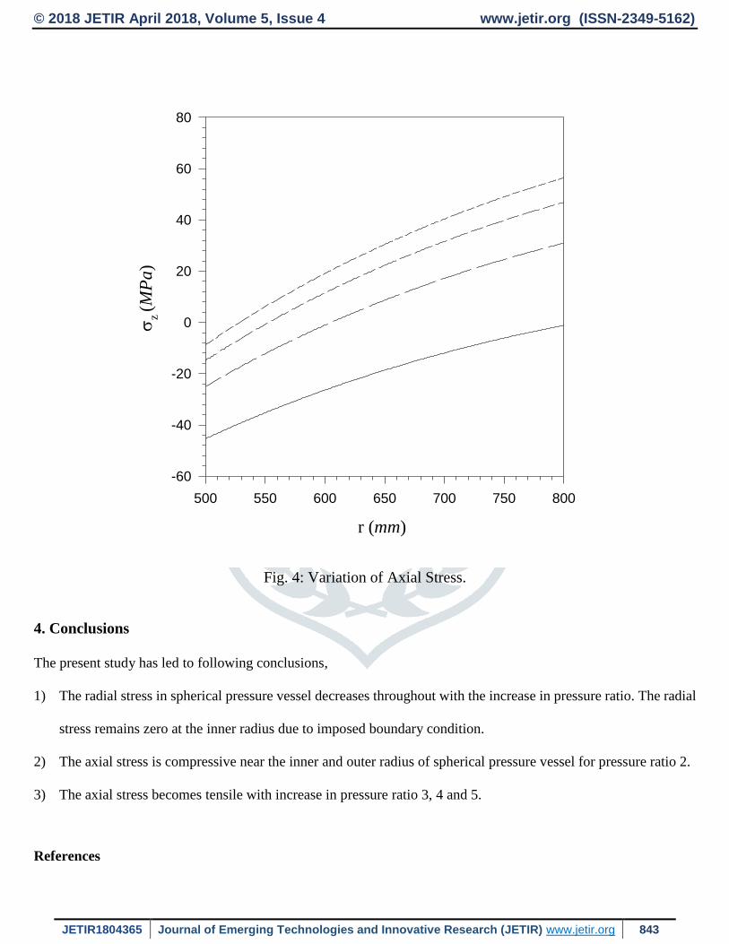
The tangential stress 𝜎𝜃 and axial stress 𝜎𝑧 remains equal due to spherical symmetry and observed to increase with
radius. Further value axial stress remains compressive at inner and outer radius for pressure ratio 2. On the other
hand, the stress become tensile at middle portion as pressure ratio is increased from 2 to 3. Further increase in pressure
ratio from 4 to 5) leads to shift in tensile axial stress near inner region of sphere. Further the distribution of axial
stress remain parabolic in nature Fig.4.
© 2018 JETIR April 2018, Volume 5, Issue 4 www.jetir.org (ISSN-2349-5162)
JETIR1804365 Journal of Emerging Technologies and Innovative Research (JETIR) www.jetir.org 843
r (mm)
500 550 600 650 700 750 800
z (M
Pa)
-60
-40
-20
0
20
40
60
80
Fig. 4: Variation of Axial Stress.
4. Conclusions
The present study has led to following conclusions,
1) The radial stress in spherical pressure vessel decreases throughout with the increase in pressure ratio. The radial
stress remains zero at the inner radius due to imposed boundary condition.
2) The axial stress is compressive near the inner and outer radius of spherical pressure vessel for pressure ratio 2.
3) The axial stress becomes tensile with increase in pressure ratio 3, 4 and 5.
References
© 2018 JETIR April 2018, Volume 5, Issue 4 www.jetir.org (ISSN-2349-5162)
JETIR1804365 Journal of Emerging Technologies and Innovative Research (JETIR) www.jetir.org 844
1. Bayat Y., Ghannad M. and Torabi H. (2012). “Analytical and numerical analysis for the FGM thick sphere
under combined pressure and temperature loading”. Journal of Archive Applied Mechanical, Vol. 82, No. 10,
pp. 229-242.
2. Bhatnagar N. S. and Arya V. K. (1974). “Large strain creep analysis of thick-walled cylinder”. International
Journal of Non Linear Mech., Vol. 9, No. 2, pp. 127-140.
3. Bhatnagar N. S. and Arya V. K. (1975). “Creep of thick-walled spherical vessels under internal pressure
considering large strain”. Indian Journal of Pure and Applied Mathematics, Vol. 6, No.10, pp. 1080-1089.
4. Bhatnagar N. S. and Gupta S.K. (1969). “Analysis of thick-walled orthotropic cylinder in the theory of creep”.
Journal of Physical Soc. of Japan, Vol. 27, No. 6, pp. 1655-1662.
5. Durban D. (1982). “Thermo-plastic/elastic behavior of a strain hardening thick walled sphere is presented with
an exact solution which is subjected to a radial temperature gradient”. International Journal of Solid Structures,
Vol. 19, No.7, pp. 643-652.
6. Durban D. and Baruch P. (1974). “Behavior of an incrementally elastic thick walled sphere under internal and
external pressure”. International Journal of Non-Linear Mechanics, Vol. 9, pp. 105-119.
7. Johnson A.E. and Khan B. (1963). “Creep of metallic thick-walled spherical vessels subject to pressure and
radial thermal gradient at elevated temperatures”. International Journal of Mechanical Science, Vol. 5, pp. 507-
532.
8. Johnson W. and Mellor P.B. (1961). “Elastic plastic behaviour of thick walled spheres of non-work hardening
material subjected to a steady state radial temperature gradient”. International Journal of Mechanical Science,
Vol. 4, pp.147-158.
9. Miller G. K. (1995). “Stresses in a spherical pressure vessel undergoing creep and dimensional changes”.
International Journal of Solids and Structures, Vol. 32, No.14, pp. 2077-2093.
10. Singh T. and Gupta V.K. (2009). “Effect of material parameter in steady state creep in a thick composite
cylinder subjected to internal pressure”. The Journal of Engineering Research, Vol. 6, No. 2, pp. 20-32.
11. Singh T. and Gupta V.K. (2011). “Effect of anisotropy on steady state creep in functionally graded cylinder”.
Composite Structures, Vol. 93, No. 2, pp. 747-758.
© 2018 JETIR April 2018, Volume 5, Issue 4 www.jetir.org (ISSN-2349-5162)
JETIR1804365 Journal of Emerging Technologies and Innovative Research (JETIR) www.jetir.org 845
12. Sultana, N. and Mondal, (2012). “Design of spherical vessel considering barichinger effect”, International
Journal of Research in Engineering and Applied Sciences, Vol. 2, No. 2, pp. 696-719.
13. You L. H. and Ou H. (2008). “Steady-state creep analysis of thick-walled spherical pressure vessels with varying
creep properties”. Journal of Pressure Vessel Technology, Vol. 130, No. 1, pp.14501-14505.