
SECOND REMODELLING PROPOSED FOR BALLOKI...
49
Paper No. 665 SECOND REMODELLING PROPOSED FOR BALLOKI HEADWORKS Muhammad Aslam Chohan
Transcript of SECOND REMODELLING PROPOSED FOR BALLOKI...

Paper No. 665
SECOND REMODELLING PROPOSED FOR BALLOKI HEADWORKS
Muhammad Aslam Chohan

174 Chohan

Pakistan Engineering Congress, 70th Annual Session Proceedings 175
SECOND REMODELLING PROPOSED FOR BALLOKI HEADWORKS
Muhammad Aslam Chohan1
1. THE HEADWORKS 1.1 Balloki Headworks on river Ravi is located at a distance of about 42 miles
from Lahore in the South-West direction. This structure was constructed during the years 1906-13 but became operational in the year 1917 when the off-taking canal and its main irrigation channels could be put on ground. The headworks was a part of the Triple Canal Project System (Upper Jhelum, Lower Chenab and Lower Bari Doab Canals Group) by which the flow of river Ravi had been planned to be supplemented via the outfall of Upper Chenab Canal (located on the right flank) for utilization in Lower Bari Doab Canal placed at left bank of Balloki. The structure was thus initially termed as Level Crossing Balloki. Later on it took the role of a headworks when due to frequent damage of upper Chenab Canal by floods in its portion of riverian belt, the contribution of water from this canal had to be shifted quite upstream via Deg Nallah Outfall. Historically the flow of water in river Ravi particularly during winter season remains very low and independently it could not support the project conceived for Lower Bari Doab Canal System. To augment the discharge of Ravi river in the low flow times, supplemental supply from river Chenab via Upper Chanab Canal had become essential for making the Lower Bari Doab Canal System technically and economically viable.
1.2 The upstream floor of the headworks had been kept very wide (214 ft) primarily to provide a pacca path for the flow of Upper Chenab Canal water from right flank of the headworks on to the head regulator of Lower Bari Doab Canal off-taking from left flank. With shifting the overflow point of Upper Chenab Canal upstream, bela formation in front of right bays of the headworks began to develop. This resulted into development of parallel flow along the upstream floor while operating the right bays of the headworks during floods. On this account, the upstream floor in course of time got seriously damaged particularly in the years 1954 & 1955 when very high discharge of 175,500 & 144,360 cusecs respectively passed through the barrage. The damage to the floor was partially repaired in the year 1956-57, by simultaneously constructing a Pitched Island 1500 ft. long with stone protected mole nose of 400 ft. diameter. The earthen shank of this work was made to join with the gates of bays No. 20 & 21, thus making them no-operable.
1 (Retd.) Secretary to Government of the Punjab, Irrigation and Power Department, 77-Shah
Jamal Colony, Ichhra, Lahore.

176 Chohan
1.3 Balloki Headworks had originally been constructed for withdrawal of 6900 cusecs into the Lower Bari Doab Canal having a gross command area (GCA) of 1.822 million acres and culturable command area (CCA) of 1.47 million acres. With the partitioning of the sub-continent into Indo Pak segments in the year 1947, the flow of river Sutlej was blocked by India. This deprived irrigation and drinking water facility in the areas dependent on that source of Pakistan side. Balloki Sulemanki Link off-taking from the left bank of this headworks had therefore to be constructed in haste with a discharge of 15,182 cusecs in the year 1954 to provide water in the Sutlej river for feeding the canals of Pakistan previously dependent on that source. This link was also made to provide on its way, the irrigation water to the lower channels of Depalpur Canal System, which hitherto were getting water from Ferozepur Headworks of Sutlej river now under Indian control. The link canal has thus saved from devastation a GCA of 0.654 or CCA of 0.615 million acres of the 10 direct off-takes of Lower Depalpur Canal System and a GCA of 3.366 or CCA of 2.444 million acres of Forwah, Eastern Sadiqia and Pakpattan Canals off-taking from Sulemanki Headworks. The total area benefited from Balloki Headworks works out to GCA 5.842 or CCA of 4.729 million acres which is about 23% of the total CCA of the Punjab Province.
1.4 River Ravi brings down very nominal flow below the first headworks on it namely Madhopur in India. On this account it has a characteristic of taking sharp loops which bring under attack even the distant abadies along its route. This behaviour is observed close to the headworks also and consequently a large number of river training works have been put on ground to tame the river and ward off attack at the marginal bunds. At present apart from the Pitched Island and Guide Banks there exist a battery of 11 spurs on the upstream and 3 spur on the downstream sides of the headworks. Location of the Barrage, ancillary structures and the layout of the training works are shown at Figure-1.
1.5 Layout of the Barrage and Head Regulators are shown on Figure-2 with salient features as under:-
• Width of Barrage between abutments 1646.5 ft • Number of bays 35 with 34 piers each 7.25 ft. wide • Clear width of bays and waterway 40 ft. each with total
waterway of 1,400 ft. • Upstream floor level R.L. 621.0 • Downstream end floor level R.L. 615.5 • Weir Data Original After Remodelling
1911-13 in the year 1964-65

Pakistan Engineering Congress, 70th Annual Session Proceedings 177
Crest level R.L. 622.5 R.L. 624.5 Max. flood capacity (Designed) 139,500 225,000 Normal Pond level R.L. 632.0 R.L. 633.0 Upstream floor length 214 ft 119.5 ft (upper part of damaged floor is no
more effective) Downstream floor length 109.5 ft 116.3 ft Maximum Head across 18 ft 17.5 ft (restricted to 13 ft) Crest width 11 ft 5.0 ft High Flood level upstream R.L. 637.0 R.L. 638.0 • Discharge of B.S. Link (Original) 15,182 cusecs 1st Remodelling year 1964-65 18,500 cusecs 2nd Remodelling year 1987-88 22,000 cusecs 3rd Remodelling (underway) 24,500 cusecs • Discharge of LBDC (Original) 6,900 cusecs 1st Remodelling 7,600 cusecs 2nd Remodelling (year 1964-65) 8,650 cusecs 3rd Remodelling conceived in the
year 1984 (still underway) 9,841 cusecs Typical X-Sections of the Weir, Head Regulators of B.S. Link & LBDC as existing after remodelling of the year 1964-65 are shown on Figure-3.
2. REMODELLING OF YEAR 1964-65 2.1 With the conclusion of Indus Water Treaty in the year 1960, the control of
three eastern rivers (Sutlej, Beas & Ravi) was given to India and the demand of canals in Pakistan situated on those rivers had been agreed to be met with from the flows of Western rivers (Chenab, Jhelum & Indus) by constructing storage dams and link canals. This put additional load on Balloki Headworks for meeting the demand of truncated canals of Depalpur System (previously getting supply from river Sutlej through Ferozepur Headworks) and the canals of Sulemanki Headworks on Sutlej river. To ensure reliable delivery of water to the eastern river from this source, the structure at Balloki had to be made safe for meeting the challenges of the changed environments. Towards this end, exhaustive remodelling of the headworks was taken up under Indus Basin Replacement Plan and essential works completed in the year 1964-65. Detail of works then taken up is contained in the first paper of the author

178 Chohan
titled “Remodelling Balloki Headworks” – Paper No. 375 of the Pakistan Engineer Congress – Year 1966. A brief resume of these works is given below by way of elucidation:
• 214 ft wide upstream floor of the headworks in the left half portion had been seriously damaged on the upper side of the well line due to swirls and parallel flow. Abnormal length of upstream floor was considered liable to face similar behaviour in future unless adequately strengthened and protected by a deep cut off. The best option appeared in the curtailment of the upstream floor width consistent with the requirement essential for exit gradient and head across limit controls. The upstream floor was thus assumed to be non-existent on the upper side beyond the well line i.e. reduction in the upstream floor width from 214 ft. to 119.5 ft.
• The damage to the upstream floor in certain portions had extended even inside of the well line which had to be repaired and floor protected to prevent further damages. A reliable deep cut off line of steel sheet pile was provided on the upstream end of the well line cut off in the entire Barrage width as well as in front of the LBDC head regulator.
• The well line at the downstream end of the floor seemed to have gaps in between. Sand blowing springs on the downstream used to be noticed and as such a reliable cut off at the downstream end was essential to check movement of fines from the sub-strata. A deep steel sheet pile line was therefore provided at the downstream end of the pacca floor just below the well line to make the structure safe against piping and exit gradient corresponding to planned raising of the pond level.
• Damage to the stone apron on the down stream had been a phenomena of common occurrence due to non-formation of a proper hydraulic jump viz-a-viz non-dissipation of residual energy, as no energy dissipation devices even in the form of friction blocks existed on the structure. After conducting model studies, a 1.5 ft. high baffle wall was provided at the end of downstream floor coupled with an overiding row of friction blocks (2.0 ft cubes) and triangular block shoots at its downward slope end.
• The downstream side of the round piers were made cut water type by extending in a length of 13 ft and tapering the width of 7.25 to a round end of 2.0 ft. dia at the end for a streamline flow and to avoid formation of eddies and swirls there. This provision also helped in the formation of a better hydraulic jump downstream which with previously round piers had been rough, uneven and generated reverse flow behind the piers. This had been done on the basis of model studies.

Pakistan Engineering Congress, 70th Annual Session Proceedings 179
The aforementioned changes incorporated as a result of model testing are depicted on the photograph annexed as Figure-4.
• Zone of inverted filter at the downstream end of floor was practically missing due to repeated damage to the concrete blocks by excessive scour. A wide non-settling zone of graded inverted filter and concrete blocks resting over it (width 30′-9″) was provided afresh. This was followed by another row of 15.75 ft. wide concrete block zone and then 60 ft. wide and 4 ft. thick stone apron for keeping scouring/settlement zone far away from the impervious structure.
• There was an acretionary trend in the river on the downstream side at the time of its remodelling in 1964-65, as a result of which modular functioning of the barrage had been seriously hampered. The crest was therefore raised by 2.0 ft i.e. from RL 622.5 to RL 624.5 for securing better submergence/drowning ratio, simultaneously raising of the high flood limit on the upstream side of barrage by 1.0 ft i.e. from R.L. 637.0 to 638.0. In this way the discharging capability of the barrage was increased from previous of 139,500 cusecs to 225,000 cusecs. The concrete block and stone apron zones were accordingly improved to cater for the higher intensity of flow both on upstream and downstream sides.
• A row of sheet pile line was provided on the downstream end of LBDC Head Regulator floor, as no cutoff existed there previously.
• The normal pond on upstream of the barrage was raised by 1.0 ft. i.e. from RL 632.0 to 633.0 to enable increased withdrawal into B.S. Link from 15,182 cusecs to 18,500 cusecs necessitated by the water requirement at Sulemanki Headworks, thus resulting in the construction of 2nd B.S. Link Canal off-taking from R.D. 72 of the Link lower down.
• The earthen shank of Pitched Island was protected with stone pitching upto a length of 900 ft from the gate line to avoid its damage by river flow during floods.
• Sand blowing springs had been noticed in the past and the structure being old, possibility of cavities and runnels under the same could be suspected. Holes at 40 ft. interval in 4 rows (near the well line and glacis toe on upstream side, near pier nose and near the baffle wall on the downstream side) were drilled and sub-strata grouted initially with cement sand and then with neat cement at a pressure of 4 to 5 lbs/sq inch. The holes did not take much grout either way indicating no noticeable weakness of sub-strata.
The aforementioned changes have been exhibited on the Layout Plan and typical cross-sections of the structure at Figure-2 & 3 respectively.

180 Chohan
3. NEED FOR SECOND REMODELLING 3.1 With the conclusion of Indus Water Treaty and construction of replacement
works, the pattern of river flows at Balloki has undergone a drastic change. The demand of withdrawals into the off-taking channels progressively went up with resultant rise in the pond level and this trend is expected to continue in future as well. The barrage faced an exceptionally high flood (ever maximum) in the year 1988 which indicated deficiencies in handling such big magnitude of river flow in future. The masking of right side barrage continued unabated and its discharging capacity became no more reliable. The accretionary trend of the river downstream of barrage which existed during sixties took a reverse trend of retrogression. This has resulted in damage to the downstream loose protections. Century old gates/ gearing operating machinery also showed signs of decay and breakdown of some parts. Added thereto a feeling of subsistence of sub-surface strata below the impervious concrete structure somehow creeped in necessitating investigations to ascertain present state of affairs. The barrage is performing a pivotal role in sustaining the agriculture of a vast area dependent upto river water deliveries. Any malfunctioning of its defined function is liable to create a crisis situation resulting in untold misery to a vast populace of the country.
3.2 To examine the effect of aforementioned changes, it had been considered desirable to adopt necessary protective measures so that the safety of the structure and its operational capability can be relied upon in the next few decades say for 50 years or more. For a critical review of the situation and to develop proposals for incorporating desirable changes in the system, study was entrusted to a group of Consultant’s joint venture comprising Associated Consulting Engineer (ACE), Engineering General Consultants (EGC) and ARCADIS Euroconsult – Netherlands for whom the author participated as an Advisor. The studies conducted by this group and model study results derived under their supervision have been availed in the presentation of the paper.
4. FLOOD STUDIES 4.1 Flood study is important with respect to the capacity of the structure to pass
a flood of estimated magnitude. The result of frequency analysis is used in deriving a design flood value to be adopted at a site. Return period of 100 years is generally used in the design of important/hydraulic structures on rivers in Pakistan where possible consequences of failure are very serious. The river flow records and data series of peak discharges is available for a sufficient long period at this site. Peak flows at Balloki from the year 1922 to 2003 have been depicted in Table-1 with histogram at Figure-5. Based on this data flood frequency analysis was conducted for various return periods using the following three distributions:
• Gumbel Extreme Value Type-I (EVI). • Pearson Type-III.
Pakistan Engineering Congress, 70th Annual Session Proceedings 181
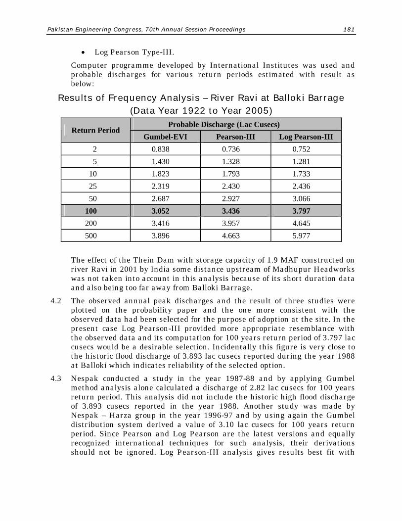
• Log Pearson Type-III. Computer programme developed by International Institutes was used and
probable discharges for various return periods estimated with result as below:
Results of Frequency Analysis – River Ravi at Balloki Barrage (Data Year 1922 to Year 2005)
Probable Discharge (Lac Cusecs) Return Period
Gumbel-EVI Pearson-III Log Pearson-III 2 0.838 0.736 0.752 5 1.430 1.328 1.281 10 1.823 1.793 1.733 25 2.319 2.430 2.436 50 2.687 2.927 3.066 100 3.052 3.436 3.797 200 3.416 3.957 4.645 500 3.896 4.663 5.977
The effect of the Thein Dam with storage capacity of 1.9 MAF constructed on
river Ravi in 2001 by India some distance upstream of Madhupur Headworks was not taken into account in this analysis because of its short duration data and also being too far away from Balloki Barrage.
4.2 The observed annual peak discharges and the result of three studies were plotted on the probability paper and the one more consistent with the observed data had been selected for the purpose of adoption at the site. In the present case Log Pearson-III provided more appropriate resemblance with the observed data and its computation for 100 years return period of 3.797 lac cusecs would be a desirable selection. Incidentally this figure is very close to the historic flood discharge of 3.893 lac cusecs reported during the year 1988 at Balloki which indicates reliability of the selected option.
4.3 Nespak conducted a study in the year 1987-88 and by applying Gumbel method analysis alone calculated a discharge of 2.82 lac cusecs for 100 years return period. This analysis did not include the historic high flood discharge of 3.893 cusecs reported in the year 1988. Another study was made by Nespak – Harza group in the year 1996-97 and by using again the Gumbel distribution system derived a value of 3.10 lac cusecs for 100 years return period. Since Pearson and Log Pearson are the latest versions and equally recognized international techniques for such analysis, their derivations should not be ignored. Log Pearson-III analysis gives results best fit with

182 Chohan
actual data. Its derivation of 3.797 lac cusecs for 100 years return period would therefore be a more reliable option to adopt at this site.
5. FLOOD MANAGEMENT 5.1 Design discharge of 3.797 (say 3.8) lac cusecs has been derived to hold good
for 100 years return period. The barrage with all bays in operation is presently designed for 2.25 lac cusecs with upstream high flood level limit of 638.00. The balance discharge of 3.8 – 2.25 = 1.55 lac cusecs, if pushed through designated breaching sites in the right marginal bund (R.D. 12 to R.D. 49) as presently being practiced will be catastrophic for the area that would get inundated (being thickly populated and cultivated by rains, tubewells and canals – Figure-6). Arrangement should therefore be devised to handle the derivated flow to a maximum extent through the barrage gates without impairing the safety of the structure and also from the right marginal bund side by minimizing the damage of inundation by floodwater. Various options to handle this situation are discussed in the paragraphs to follow:-
A. Improving The Barrage Capacity 5.2 It is desirable to pass maximum flood discharge through the barrage by
incorporating feasible amendments/modifications in it. It is visualized that the combined effect of the total discharge of 3.8 lac cusecs passing across the structure through barrage and breaches would generate a flood water level of 637.00 on the downstream side of the headworks (a level attained during super high flood of 3.90 lac cusecs in the year 1988). In this situation the barrage in its present form of upstream designed HFL 638.0 with two bays blocked by Pitched Island and adjoining two bays practically non-functional, will not be able to pass a discharge more than 2.0 lac cusecs as against the designed capacity of 2.25 lac cusecs.
5.3 To maximize the barrage capacity, a modular operation of the structure would be desirable to maintain. This would become feasible by raising the high flood limit upstream, say by one foot i.e. upto R.L.639.00. By so doing the discharge capacity of the barrage would increase to about 2.30 lac cusecs.
If the earthen shank of the pitched island is replaced by a masonry/concrete wall, the two totally and adjoining partially masked bays can be made fully operational and in that situation the maximum discharge through the barrage would increase to about 2.60 lac cusecs. To confirm this derivation, the testing of such position was done on the comprehensive physical and sectional model of the weir, by the Irrigation Research Institute which established a discharge of 2.57 lac cusecs. This provision still leaves a gap of 3.8 – 2.57 = 1.23 lac cusecs to be catered for through some other feasible arrangement.
5.4 On raising the high flood level limit upstream by one foot, the flow through the Barrage Works out to 2.57 lac cusecs against existing capacity of 2.25 lac

Pakistan Engineering Congress, 70th Annual Session Proceedings 183
cusecs. The intensity of flow over the structure thus increases by about 14%, which remains within safe limits of the existing weir section as tested on the model for energy dissipation. The raising of flood limit on upstream of the barrage from R.L.638.00 to R.L.639.00 is therefore advisable to maximize flow through the Barrage without impairing its safety. Corresponding raising of the upstream training works will however need to be done depending upon higher flood levels that might be generated against them.
B. Breaching Section Option to Pass Surplus Discharge – Change in Current Practice
5.5 There are two designated breaching sites on the right side. The site between R.D 48,000 – 48,500 Madhodas bund (Figure-6) near end point of right marginal bund is called as site No. 1 and between R.D 12,500 – 13,000 of the marginal bund as site No. 2. Another suitable breaching site can be incorporated between R.D 8,500 – 9,000 which being near the barrage will perhaps be more suitable in providing immediate relief to the structure.
5.6 The breach site at Madhodas bund is too far off and does not provide immediate relief at barrage. Addedly its flow inundates a vast belt of developed cultivated area. It would be desirable to abandon this site and replace this site with the one newly proposed between R.D 8,500 – 9,000 right marginal bund and thus confine the inundation area limit within the riverian zone upto the left side of abandoned Upper Chenab Canal (UCC). The ground levels on the right of this abandoned canal are higher and majority of inundated water from the breach of Madhudas bund even otherwise comes towards the above riverian belt via a causeway in the metalled road near the police check post at a distance of 12,500 ft. from the Barrage.
5.7 The area from headworks upto police check post is low lying. The metalled road in this reach is about 4 to 10 ft higher than the adjoining ground. Further away the metalled road is virtually at ground level. The water from breaches at present goes to river by overtopping the road and causing breaches in this reach of the road upto Police Post.
A big depression with pool of deep water exists even today at a distance of 2,400 ft from the headworks where the road is made to breach first on making cuts in the right marginal bund. To pass the floodwater of breaches hitting the metalled road (upto Police checkpost), it would be desirable to construct 2 bridges of appropriate size on the depression sites at a distance of 2,400 ft; and 6,000 ft from the headworks to avoid road traffic disruption. General scheme of this flood routing is shown in red color at Figure-6.
C. Annexe Weir 5.8 M/s Nespak – Harza carried out study in the year 1996-97 under Flood Sector
Project which derived a discharge of 3.10 lac cusecs for 100 year return period by Gumbel Distribution technique and proposed construction of an Annexe Weir of 8 bays with lower crest of 2 ft on the right flank to pass a balance
184 Chohan
discharge of 3.10 – 2.25 = 0.85 lac cusecs through it (location at Figure-12 and layout at Figure-13). With the expected water levels 637.0 to be generated on the downstream and raised flood level limit of 639.0 on the upstream of barrage, the annexe weir of lower crest will be able to handle an additional discharge of about 0.68 lac cusecs. In this way, the barrage with annexe weir provision will take a maximum discharge of 2.57+0.68 = 3.25 lac cusecs. A balance of 3.8 – 3.25 = 0.55 lac cusecs would still remains to be catered for via breaches in the right marginal bund or through some type of an overflow spillway placed at a suitable location.
5.9 Provision of an Annexe Weir on the right flank will tantamount to increasing the barrage length from existing of 1,646.50 ft to about 2,067 ft. The flow of river at Balloki for nearly 10 months in a year hardly meet canals water requirement off-taking on left flank and no escapage across the barrage takes place. With this flow pattern, the right half of the barrage remains liable to silt deposition and growth of bela in close vicinity of the structure tending to block the floodwater passage in that part. The Annexe Weir will also be prone to such adversaries and at times this part may not take its contemplated share of discharge to pass it lower down. The provision of Annexe Weir will encounter these snags, may be to a greater extent being further on the right side of barrage; more so if ample surplus flows during the dry spells of a few years do not become available for flushing/keep clear the approach channel of river leading upto Annexe.
D. Overflow Spillway 5.10 The flood water from breaches of the right marginal bund causes lot of
damages to vast agriculturally developed and thickly populated area by inundation/ submergence. Property loss, damage to infrastructure and disruption of traffic over long period disturbs public life and generate strong resentment from the direct affectees. With the passage of time, pressure on land is bound to increase and the practice of making breaches in the marginal bund may no longer remain workable.
5.11 Constructing an overflow spillway of adequate capacity at a suitable location is a workable alternative to escape the excessive river flow for releasing pressure on barrage. It is felt that an overflow spillway constructed at a short distance upstream from the headworks between spur No. 10 and spur No. 3 may be desirable to incorporate in the system. The operation of this spillway has been tested on a comprehensive physical model at Nandipur and suggested mode gives satisfactory performance.
D-I Spillway with Provision of Annexe Weir 5.12 The provision of Annexe Weir at the right flank of barrage leaves a balance
discharge of 0.55 lac cusecs (derived in para 5.5) to be catered for by the spillway. If the crest of this structure is kept one foot above the proposed optimum raised pond R.L. 634.0 for canal withdrawals at the barrage, the spillway shall begin to operate when flow in the river upto the high flood

Pakistan Engineering Congress, 70th Annual Session Proceedings 185
stage limit can be made to pass through the barrage at that pond level (1.30 lac cusecs designated capacity of high flood stage flow) and thus provides simultaneous relief to be barrage structure matching with the rising river flood water.
5.13 The discharge capacity of this spillway will depend upon the width of its crest and the flood heights that would be generated by the rising flood. A spillway width of 800 ft with crest at R.L. 635.0 and HFL 642.0 expected at this site corresponding to 3.80 lac cusecs (para 4.2), a discharge of 55,000 cusecs to 60,000 cusecs (derived at para 5.8) would be escaping from this structure. The location of the spillway and its geometrical configuration are shown at Figure-7 and Figure-8.
5.14 The flood flow from the spillway in this arrangement is planned to be kept within the limits of newly proposed tie bunds upto the junction of Balloki-More Khunda road where a wide bridge would need to be constructed at location shown in Figure-7 and geometrical details at Figure-9 to avoid public property damage. Lower down a natural depression already exists to lead the water on to the river channel about a mile downstream of the barrage.
D-II Spillway without Provision of Annexe Weir 5.15 The introduction of Annexe Weir and its operational snags as indicated at
para 5.9 suggests consideration of an option other than its provision. In such a situation disposal of 1.23 lac cusecs over and above the barrage handling capacity as derived at para 5.3 would need to be catered for. Overflow spillway of this capacity placed between spur No. 10 and spur No. 3 as already discussed at para 5.11 (Figure-7) would be a desirable option to adopt by modifying the shape, size and geometry. A mild arc shape with a lower crest of the spillway can fit in at the site indicated already. A spillway of 1,050 ft length with lower crest at R.L. 632.0 will be able to escape the contemplated discharge of 1.23 lac cusecs through it. The dimensions of spillway structure corresponding to higher intensity of flow and approach/exit condition will get modified as shown in Figure-11 and Figure-12. The length of bridge at Balloki-More Khunda road for floodwater passage can also be suitably increased to pass the increased quantum of flow.
5.16 The low crest R.L. 632.0 proposed for the spillway would be 2 ft below the canals operative maximum pond R.L. 634.0 to be created at the barrage. A small bund would therefore need to be constructed on the upstream of the spillway as shown in Figure-11 to avoid uncontrolled escapage of water through it. A few cuts can be made in this bund (like the one at Mangla Dam for operating emergency spillway) when overflow spillway is required to be activated

186 Chohan
E. Preferable Choice 5.17 Various options to handle the incoming floodwater of over and above
indicated higher discharge capacity of existing barrage (2.57 lac cusecs – para 5.3) i.e. balance of 1.23 lac cusecs flow have been narrated in para 5.5 to para 5.16. The best choice seems in constructing an overflow spillway of low crest for passing a discharge of 1.23 lac cusecs as narrated in para 5.15 and is therefore recommended for adoption. The precise location, shape, layout and operational performance may however be tested again on the physical model depending upon river approach conditions prevailing at the time of project execution.
F. Masking on Right Upstream of Barrage 5.18 With the transfer control of 3 Eastern rivers (Sutlej, Beas and Ravi) to India,
practically no flow is coming into Pakistan from these rivers even during the monsoon season and due to construction by India of Bhakra and Pong Dams on Sutlej/Beas rivers and Thein dam on river Ravi upstream Madhopur Headworks. The canal systems of the country on these rivers are now being fed by transferring water from western rivers via link canals and storage water of dams. This has resulted in the formation of almost dry river zones below the headworks of Sulemanki and Islam on Sutlej; below Balloki and Sidhnai on Ravi, below Qadirabad on Chenab and below Rasul on Jhelum (due to Mangla storage). Heavy bela formation is taking place on the upstream of all these structures with pronounced masking opposite the right bays as all withdrawals on these barrages are from the left flank. Vegetation grow on these belas and their washing had become almost impossible, more so, because sizeable surplus flow is often not available to pass lower down even during the flood period of July to August. This phenomena has in turn been adversely affecting the discharging capability of the bays on the right side of Balloki Barrage apart from causing of parallel flow conditions from left to right side close to the structure. This state of affairs made liable to damage the upstream floor/loose stone protection of the barrage in the event of high floods and seriously impaired the discharging capacity of the structure as a whole.
5.19 Efforts made in the past to reduce development of belas/masking on the right and to make the affected bays of the structures fully operational by way of leading cuts has failed completely. A pitched Island of about 1,500 ft length with stone pitched semi circular end nose (upstream of bay 19 and bay 20) was constructed in the year 1956-57 to feed the right side of barrage from its upstream but the same also did not help much to keep the bela growth under check. Foreign experts suggest provision of dredgers at such sites which would be a very expensive prescription apart from their operational problems. Our experience of keeping dredgers for desilting of canals at Qadirabad and Trimmu has been a complete failure and the equipment had ultimately to be disposed off as scrap. Nespak-Harza in their report of 1996-97 on Balloki suggested keeping a dredger at site for maintaining a direct

Pakistan Engineering Congress, 70th Annual Session Proceedings 187
approach channel of the river on the right side for keeping that part of the weir fully operational. This provision neither suited the environments of this country nor a situation of having a direct approach channel of the river arm on that side is feasible to create at site.
G. Dividing Walls 5.20 A practical and natural solution of the problem is to keep the bela formation
tendency at some distance from the structure so that the right bays may remain fully open/operational to handle their share of discharge when required. At Balloki, it is suggested to form compartments of flow by putting Dividing Walls on the upstream side. These walls may be approximately 400 ft straight in length with slope ends of 69 ft and should be constructed after every six bays commencing from right and going upto about the middle of the structure i.e. 3 dividing walls opposite piers of bays between 17-18, 23-24 and 29-30 (Figure-7 & 12). The extreme left wall at pier No. 17 will be about 900 ft in length so as to keep flow currents of right side compartments away from the zone of canal head regulators for silt control. These walls will also need extension on the downstream floor of the barrage upto the baffle wall block to streamline the exit flow conditions. This provision will enable passing the incoming surplus/low flood flow through these compartments turn by turn and flush down deposited silt of each zone by generating silt eroding velocity of water in them. Approach of water to these compartments will in this situation be at a safe distance upstream of the barrage structure and that would obviate chances of any damage to the structure by parallel flow phenomena. The bela formation in this way will shift fairly upstream of the barrage and would thus not hamper the overall discharging efficacy of the barrage structure. Similar effect will be achieved on the Annexe Weir (if that is introduced in the system) by restricting dividing groyne/wall to a narrow width of nearly 50 ft and keeping its length as for other dividing walls. The working of the dividing walls and annexe weir in the stated position has on the comprehensive physical model testing been found to be effective in achieving the desired objectives and their indicated precise layout is as optimized on the model by the Irrigation Research Institute at Nandipur (Figure-12).
H. Removal of Pitched Island 5.21 With the provision of 3 dividing walls as proposed in para 5.20, the existence
of Pitched Island Shank (originally 1,300 ft long and a round semi circular mole head which got punctured during the floods of 1988 and is now in a straight length of about 900 ft) will become redundant and would need removal. By doing so the 2 blocked bays of the barrage will become clear to take their share of discharge. Its semi circular stone pitched mole head nose of 400 ft diameter in the proposed scheme of work is likely to create shoaling at its back too close to the weir (as also indicated on the model). The nose part of the pitched island which has already lost its identity during flood damages of over last 17 years would thus require demolition by salvaging its stone to the extent feasible.

188 Chohan
6. BARRAGE SAFETY 6.1 Soundness of Structure and Substrata To evaluate the present condition of the structure and sub-surface strata,
non-destructive testing techniques as well as other field and laboratory tests were got carried out by Central Materials Testing Laboratory (CMTL) WAPDA as listed below:
(a) Seismic Refraction: The system determines the compressional wave velocities of the materials from the surface to a specified depth. In this technique seismic (sound) velocities are generated and their arrival time through geophones is recorded via sensors and cables to the seismic recorder. The seismogram data is then transferred to the computer where it is deciphered on a special software to compute velocities of different layers. On the basis of velocities, the interpretation of each layer is made to differentiate between satisfactory and grey areas.
(b) Electrical Resistivity: This system is based on the measurement of vertical changes in the electrical properties of the surface & sub-surface materials. The equipment consists of a current transmitter, a receiver to measure the resultant potential and a set of current and potential electrodes. The results are then analysed on a computer programme to ascertain quality of various strata.
(c) Conventional Gravity: This is a geophysical method that measures minute changes in the force of earth gravity. The equipment measures gravity changes of the underlying geological structure to understand the ground beneath and detecting underground cavities.
Some of the non-destructive tests indicated above were made at a number of locations on the downstream side of the barrage floor. These tests are indicative in nature, but their results are supportive of each other to justify reliance on the derived conclusions. These tests have revealed:
(i) The stone masonry and concrete of floor to be intact at all locations except some weakness in bay No. 9 which might be due to opened up joints visible in the upper layer of the stone masonry.
(ii) The sub-strata are uniform in character with no evidence of cavities, voids, runnels or segregation.
(d) Concrete Core: Samples were extracted at 5 locations and their compressive strength varied from 4000 to 7000 lbs per square inch which is more than the expected limit.
(e) PUNDIT & Schmidt Hammer Tests: The result of 12 tests showed a uniform stone/concrete mass without cracks/ voids or segregation and strength to be more than 4000 ft.

Pakistan Engineering Congress, 70th Annual Session Proceedings 189
(f) Boreholes: 3 Boreholes ranging in depths of 24’, 34’ & 46’ in the riverbed below the barrage gave lithology of fine to medium sand with some intermix of silt and clay.
The above results indicated no evidence of weakness or a fault of any significance. The tests have established soundness of the existing structure and homogeneity of sub-strata on which the theory of uplift pressures and exit gradient as per Khosla’s CBI Publication No. 12 can be applied.
6.2 Accretion/ Retrogression Trends 6.2.1 The downstream floor level of hydraulic structures and geometry thereof are
designed keeping in view the future accretionary/ retrogressive trend of the channel lower down. Excessive accretionary trend would cause the downstream flood heights to rise which might in due course effect weir modularity resulting in reducing the discharge passage capacity of the structure. The phenomena of retrogression would conversely lower the flood heights, which in course of time may not provide adequate depth of water to form a proper hydraulic jump necessary energy dissipation. This situation makes highly turbulent water to flow lower down causing damage to protection works as well as endangering the safety of the structure. Glaring example of this behaviour was noticed at Islam Headworks where soon after its construction in 1926-27, serious retrogression phenomena began to occur which in the next two to three years made the central bays to get washed away. The downstream floor was repeatedly damaged thereafter and ultimately a subsidiary weir had to be constructed immediately below the barrage in the year 1951-52 to control the situation. Similar conditions have cropped up below Taunsa & Jinnah (Kalabagh) barrages where provision of subsidiary weirs have been felt necessary and steps are underway to incorporate them in the system. At Balloki barrage on the other hand phenomina of accretion was rampant at the time of undertaking remodeling operations in the year 1964-65 as a result of which the weir crest level had to be raised by 2.0 ft. to maintain its modular behaviour.
6.2.2 A study of river channel behaviour lower down the barrage from the year 1948 to-date has been made and trend lines are plotted at Figure-12. Period from 1948 to 1955 (prior to operation of B.S. Link i.e. when only LBDC was withdrawing water from river) reflects nearly stable position with very nominal trend for retrogression. In the period from 1956 to 1969 (on additional withdrawal of river flows by B.S. Link) accretionary trend became more pronounced. From the year 1970 onwards i.e. after commissioning of Indus Basin Works and contribution of stored water supply from Mangla Dam to river Ravi via trans-river link canals, relatively silt free water reaching Balloki gradually reversed the trend towards retrogression. Presently it is more or less in a stable position that existed prior to commissioning of B.S. Link or the Indus Basin Work’s construction.

190 Chohan
6.2.3 The minimum downstream water level at present remains about 2.0 ft. above the barrage floor end. The retrogressionary trend is very mild and in the current situation it is not likely to aggravate to a situation of any alarm. There is still a margin of 2 ft. to cater for any such eventuality for long time to come. It is thus concluded that there is no cause of anxiety to the structural stability of the barrage as far as the retrogressive/ accretionary trends on the downstream of the barrage are concerned.
6.3 Exit Gradient With nil flow condition below i.e. with minimum water at R.L. 615.5 or dry
floor downstream which may be case in future times and ponded condition upto RL 635.0 on the upstream, the barrage in its present form is safe against exit gradient as its value remains within the safety factor of 7 normally taken for fine sand sub-strata.
6.4 Uplift Pressures and Floor Thickness Downstream The floor thicknesses of the existing structure are safe upto upstream ponded
water at R.L. 634.0 with nil flow or dry floor condition downstream. With pond level raised to R.L. 634.5 the middle portion of downstream floor is deficient in thickness by a meager value of 3 inches while at RL 635.0, this shortfall increases to 6 inches only which is not of much significance. Thickening of floor for added safety if resorted to would make the downstream slope more flat and crest part wider. In this position, the formation of hydraulic jump tends to shift much lower down and turbulent flow of severe nature goes beyond the limit of pucca floor to damage the loose protection works, as also tested on the model. The idea of thickening the downstream floor thus gets totally ruled out. It is therefore concluded that in a given situation, normal operative upstream pond for canals operation should not be raised above RL 634.0 so that at no stage the head across the barrage get exceeded beyond a limit of 634.0 – 615.5 = 18.5 ft. With some leakage of water from the barrage gates, the pond level can however be raised upto RL 635.0 by keeping a watch that the head across the structure does not exceed the limit of 18.5 ft.
6.5 Floor Length Downstream To aim at formation of hydraulic jump and proper dissipation of energy,
adequate length of downstream floor is required to be provided. The structure is presently designed to pass a flood discharge of 2.25 Lac cusecs with upstream HFL 638.0 and downstream HFL 635.0 (i.e. by modular operation). If the structure is made to pass a higher discharge of 2.57 Lac cusecs as derived theoretically and also confirmed by the model studies corresponding to raised HFL 639.0 and downstream flood water at R.L. 637.0 (discussed in para-5.A) the intensity of flow per foot run across the weir crest comes to 184 cusec. Analysis show that the available length of floor beyond the range of hydraulic jump formation is adequate and no extension of floor is required on that account.

Pakistan Engineering Congress, 70th Annual Session Proceedings 191
6.6 Energy Dissipation 6.6.1 At the time of remodeling the barrage in the year 1964-65, the pier ends were
made cut water type by conical extension in a length of about 13 ft to streamline the exit flow. Addedly a baffle wall 1.5 ft. high with over riding row of 2 ft. cubic friction blocks and staggered triangular block shoots at downward slope end was provided at the end of floor to help in dissipating the residual energy of hydraulic jump (Figure-4). These devices have performed their function considerably well.
6.6.2 The barrage structure on the downstream side of gate line does not have a regular glacis or cistern as is normally provided on the hydraulic structures for confining the range of hydraulic jump formation and the zone required to dissipate the residual energy. The existing downstream floor of a straight line geometry with very flat slope of 1 in 15 (see photograph at Figure-4) makes the hydraulic jump to fluctuate quite a bit at variable flow intensities. In such a situation the performance of energy dissipation devices assume a more important role. The weir section was therefore got re-tested on a sectional model in the Irrigation Research Institute at its Lahore laboratory with a view to augment the energy dissipation devices as feasible. Various options of piers extension, placing chute block and friction block rows at different location of floor were tested on the model. The best result obtained was with addition of another row of 2 ft. cube friction block resting over the horizontal portion of the baffle wall as shown at Figure-15, which would be desirable to provide.
6.7 Structural Safety The structure behaviour after the remodeling of the year 1964-65 has exposed
no malfunctioning in the last 4 decades. The high floods of the year 1973 (discharge 183,000 cusecs), year 1976 (Discharge 234,474 cusecs), year 1988 (Discharge 240,845 cusecs), year 1995 (discharge 222,800 cusecs), year 1996 (discharge 220,000 cusecs) passed through the structure safely without disturbing or dislodging any of the concrete block below the impervious floor. One row of concrete friction blocks resting over the baffle wall has also established soundness of its position to withstand high velocities/ turbulance of flow generated during super high floods at the barrage (Figure-4). Addition of another row of friction blocks at the horizontal part of baffle wall will further improve the energy dissipation effort as established on the model. No further strengthening of the weir floor is envisaged even for passing a higher discharge of 2.57 Lac cuses across the structure as now being suggested. The following works of repair may however be desirable to take up (Figure-15):
(a) Open joints of the top layer stone masonry be properly raked out and filled with rich cement sand mortar.
(b) Depressions/ settlements in the loose stone apron on the downstream side be made good by dumping heavier seized stone to avoid their picking up/ dislodging during floods of high intensity.

192 Chohan
7. CANAL CAPACITIES 7.1 Two canals take off on left side of Barrage. Lower Bari Doab Canal is being
remodeled to take a discharge of 9841 cusecs which can be drawn from its Head Regulator by maintaining the existing pond of R.L. 633.0 at the barrage. The head regulator has ample waterway and to meet even any future enhancement of discharge for withdrawal upto 12,500 cusecs raising of the pond to R.L. 634.0 is only needed. This level retains modular operation of the head regulator as water level then required in the canal would be about R.L. 632.5. These withdrawals are feasible without impairing the structural stability of the head regulator or the barrage weir.
7.2 Balloki Sulemanki Link is presently designed for a discharge of 22,000 cusecs and it is in the process of remodeling to take enhanced flow of 24,500 cusecs. The existing discharge can be handled by maintaining a pond of R.L. 634.0, but for a higher discharge of 24,500 cusecs, pond at R.L. 634.7 will be required.
7.3 The demand of water for canals off-taking directly from the link canal and those at Sulemanki Headworks is mounting every day. If a very modest flexibility of 10% is incorporated in the discharging capability of the Head Regulator, the structure is required to be made fit for passing a discharge of 27000 cusecs. For this quantum a pond R.L. 635.4 is required to be maintained. With breast wall bottom of the head regulator at R.L. 633.0, water level in the canal is not to exceed RL 632.5 to maintain modular under short flow which corresponds to a canal discharge of 28,000 cusecs. For passing this discharge pond R.L. 635.7 would require to be maintained. Further attempt to push more discharge into the link canal by any means or through any alternate source will make the canal water to rise to a situation of submerging the gate openings with consequential effect of reducing its discharge co-efficient. It is thus concluded that to draw a discharge of more than 22,000 cusecs from the existing head regulator, a pond higher than R.L. 634.0 will have to be maintained which has serious implication of barrage safety against excessive uplift pressures (para 6.4) as well as causing large scale submergence of private lands beyond the pond area acquired limits (Figure-16).
7.4 Regarding inundation of the upstream area, limiting pond level position occurs at R.L. 634.5 under a situation of low flow in the river or nil release lower down the barrage. At higher river flows with somewhat steeper water slope, inundation effect will be more pronounced indicating desirability of not exceeding the pond R.L. 634.0 from canals operation viewpoint. For forming a higher pond upto R.L. 635.5, the backwater effect would travel much upwards and cause submergence in the privately owned area of about 1100 acres (Table-2 & Figure-16). This area comprises developed cultivated land and has numerous hutments in the riverian belt. Acquisition of this area would pose socio-political/ environmental problems apart from being cost

Pakistan Engineering Congress, 70th Annual Session Proceedings 193
intensive. It is thus not advisable that the pond level on upstream of the barrage from canals operation view be allowed to exceed R.L. 634.0.
7.5 New 2nd B.S. Link Head Regulator By limiting the pond level at R.L 634.0, a discharge of 22,000 cusecs can be
passed through the existing B.S. Link Head Regulator under free flow condition i.e. without submergence of gates or its breast wall bottom. Alternative arrangement to push the additional discharge are therefore required to be devised. For this purpose a Second Head Regulator of 8 bays matching with the existing structure i.e. crest R.L. 624.84, breast wall bottom R.L. 633.0 and 24 ft clear width of each bay will require to be constructed. This arrangement with canal water at RL 632.5 below the structure will withdraw discharge of 28,000 cusecs through the two head regulators working non modularly at Pond R.L. 634.0 i.e. getting a flexibility of 14% over and above the presently planned withdrawal of 24,500 cusecs. If by remodelling the link canal, its water level at head can be lowered to a stage of regulators working modularly, the two head regulators would be capable of delivering much higher discharge to meet all time future needs of the dependent canal systems.
The second head regulator being a new construction should be constructed matching with proposed new environments i.e. high flood limit on upstream of barrage raised from R.L. 638.0 to R.L. 639.0. This head regulator is planned to be located alongside the existing regulator and at a minimum distance from it by keeping in view that its operational capability is not hampered during construction stage. It is also planned to be located at an angle of 11° with the existing structure for achieving better upstream water approach condition and also for smooth flow of the road traffic on its deck. This arrangement has been tested on model and found to be smoothy workable. Relative location of the new head regulator and its typical section are shown at Figure-12 and Figure-17 & 18.
7.6 Existing B.S. Link Head Regulator The existing regulator is safe against exit gradient for pond RL 634.5 while
the crest and glacis parts are short in thickness by about 1.5 ft. To make the existing head regulator safe against exit gradient corresponding to higher HFL 639.0 and nil flow in the link canal, a deeper end cut off is required which will be possible by providing a row of sheet pile line in the proposed downstream extension portion of the existing floor. The deficiency of downstream floor thickness at that level can be overcome by constructing a 4.0 ft. high baffle wall above the newly placed end pile line for maintaining a matching depth of water over the floor. The deficiency in floor thickness of over 3 ft at crest and glacis can be met with by extensive grouting the sub-strata of this part with cement to create a thick cement sand mass and anchoring the same suitably with the existing floor. This part is resting between the deep foundation of the bridge/ overhead deck of the regulator

194 Chohan
gates and it is hoped that a confined zone of cement grout in between will make the sub-strata solid enough in a desirable depth for safety against the effect of uplift pressure there. The proposed modification of the existing head regulator and the cross-section of the structure are shown on Figure-17 & 18.
8.0 RIVER TRAINING WORKS 8.1 General The behaviour of river Ravi is characteristics of making sharp loops which
quite often cannot be anticipated much in advance. This phenomenon brings under attack the abadies enroute at short notice. Consequently a large number of river training works in the form of spurs have been constructed all along the river course from its entry point from India at Nainankot to Sidhnai. This trend has been creating problems close to the headworks also. To ward off attack at the marginal bunds and for having favourable river approach towards the barrage, a large number of spurs have therefore been put on ground as shown at Figure-1.
8.2 Dividing Walls Something is required to be done to make the right side of the barrage fully
operational by controlling the tendency of shoal formation in the immediate vicinity of the structure. For this purpose, model studies were got conducted at Nandipur Research Station which supported the idea of constructing three Dividing Walls; two of them 469 ft long in line with barrage piers No. 23 and 29 and the third 869 ft in length at pier No. 17 as discussed in para-5.20 and shown at Figure-12. With this provision, the existence of Pitched Island becomes redundant and would need removal as also indicated by model studies and discussed in para 5.21.
8.3 Spurs The prevailing river position do not warrant construction of any additional
spur at the present. The provision of Annexe Weir on the right side of the barrage for passage of additional flood discharge across the structure (as discussed under para-5.8) however, places the nose of Spur No. 10 in direct passage of the river flow towards the Annexe. This nose will require removal and constructed in a retarded position as shown at Figure-7, if the need for constructing the Annexe Weir crystallizes at any stage. If the proposal of providing spillway of adequate capacity as discussed at para 5.15 is implemented, the nose of spur No. 10 will stay in position as existing at present.
8.4 Bunds Strengthening The training works on the upstream side of the barrage were repaired in the
recent past and strengthened corresponding to flood heights generated by the historic flood of the year 1988, when the designed HFL 638.0 on the upstream of the barrage had been attained. With the proposal to raise HFL limit by one foot to RL 639.0 at the barrage and escapage of surplus floodwater through

Pakistan Engineering Congress, 70th Annual Session Proceedings 195
the proposed spillway located near the headworks, corresponding, rise of water levels along the training works is bound to take place. The extent of rise in water level along the training works as indicated on the model should be taken into account to strengthen these works.
9. PRESSURE PIPES 9.1 Pressure pipes are important devices to monitor the health of the structure.
The pipes installed at the barrage after presentation of Khosla’s theory of uplift pressures (CBI Publication No. 12) remained partially functional upto the year 1970, but thereafter the readout points at piers top got blocked on widening of the road bridge. Since then the facility to monitor the behaviour of subsurface flow and condition of uplift pressure has ceased to exist. This data is an important indicator for keeping under watch the structural stability parameters and to devise timely remedial arrangements. It is proposed to install both electrical instruments and standpipe reading system at selected location of all the hydraulic structures of the barrage to monitor and analyze the data. The readout points of the standpipe piezometers can be placed at the top of the piers (extended portion) while the data from the electrical piezometers will need to be recorded in a central control room where after due processing/analysis the print outs of the results can be taken out.
The number of section lines suggested on the various structures and the requirement of piezometers at pertinent sites is given below:
(a) Seven section lines equally spaced below the barrage floor, each having 5 to 7 electrical and standpipe points to monitor. Four section line of right side can have two points below the upstream floor which would be possible to install while uncovering the area to construct the dividing walls. The downstream floor area will have 5 reading out points in all the 7 section lines.
(b) The annexe weir (if constructed) will have 4 section lines each having 9 points for electrical and standpipes reading.
(c) Three rows on the downstream side of the existing B.S.Link head regulator each consisting of 3 electrical and standpipe points.
(d) Three rows on 2nd B.S.Link head regulator each having 8 electrical and 8 standpipe points.
10. REGULATING MACHINERY 10.1 The gates and hoisting system is nearly a century old now and has started
showing operational defects. Frequently occurring defects in the roller trains, roller track and other components has made the gates operation hard and difficult. Moreover, in the present fast moving age, the decades old manually operated gate system appears cumbersome, being dependent on a large standby labour force. It is therefore proposed to supplement the system with

196 Chohan
electrically operated hoisting equipment in addition to the existing manual system at all gates of barrage, proposed annexe weir (if provided) and the head regulators of the canals. The existing hoisting machines can be supplemented with electrical hoisting mechanism which will be capable of remote control operation by getting signals from a central control room. Control panels and gates position indicators can also be installed at the hoisting machines of each gate with monitoring arrangement in the control room. Schematic view of the proposed arrangement at the hoisting machines is shown at Figure-19.
10.2 The bottom of the 12.5 ft. high gates in fully raised position reaches upto R.L. 631.50 while designed HFL is 638.0 (now planned at R.L. 639.0). A free flow condition across the barrage during high flood stages is therefore not possible at present which in turn effect the discharging capacity of the structure. The present limit of raising gates and roller trains is upto the length of the guiding track which ends at pier top R.L. 644.0. This permits the lifting of gates upto a height of 7.0 ft. only. To make the gates move up clear of the HFL limit of 639.0, the guiding track of the gates is required to be extended on both sides of the piers in a length of 8.0 ft (Figure-20). Similar extension in case of annexe weir will be of the order of 10.0 ft. because of 2.0 ft. longer height of those gates. In case of LBDC head regulator, extension piece of 2.0 ft. in its upper gate leaf would be needed to check entry of flood water into the canal corresponding to new proposed HFL 639.0.
10.3 The damaged members of the gates should be replaced and existing roller trains either re-set or replaced to ensure proper gates movement. Linkwise damaged/ pitted/ wornout roller tracks should be re-habilitated by machining to smooth surface of those parts and then affixing new iron plates of proper thickness and hardness (which should be more than the hardness of rollers surface) with countersunk screws and epoxy adhesive. Such a treatment will ensure smooth operation of the roller trains along their guiding tracks.
10.4 Excessive leakage of water takes place in closed position of gates from sides and bottom. Neoporan rubber seals of proper shapes and thickness should be provided at these places by attaching through corrosion resistant bolts. Similar provision is needed at the gates of the head regulators.
10.5 Repair and replacement of some staunching rods and rocker assemblies is needed to overhaul the system fully.
10.6 Perhaps maintaining a properly well-equipped workshop capable of on-site solving the day-to-day snags and positioning of qualified/ trained staff is also an important call of the day to professionally manage the planned somewhat sophisticated system.
11. ACKNOWLEDGEMENTS

Pakistan Engineering Congress, 70th Annual Session Proceedings 197
The author expresses his deep gratitude to Mr. Muhammad Akhtar Rana – Ex Secretary I&P Deptt; Mr. Ahsan Hassan Zaidi – Ex Chief Engineer I&P Deptt and Mr. Muhammad Ashraf Khokhar – Ex Superintending Engineer I&P Deptt for their candid help in technical dialogues. Thanks are due to Mr. Javaid Iqbal Awan, Senior Mechanical Engineer; Mr. Muhammad Aslam Bhatti, Principal Geo-Tech Engineer; and Mr. Shakil Ahmad, Senior Hydrologist of ACE in providing guidance of their fields. The author is highly appreciative of the support given by Central Monitoring Testing Laboratory (CMTL) WAPDA and Irrigation Research Institute (IRI) Lahore for conducting tests of great value. Above all author is grateful to Mr. Muhammad Fiaz Khan, CAD Operator of ACE for his willing help in preparing the sketch drawings and type work.

198 Chohan
Table – 1: Annual Peak Discharges of River Ravi below Balloki Headworks (Data Year 1922 to Year 2003)
Discharge Discharge Discharge
Year Barrage
Breaches/ Canals
(Estimated)
Total Annual
Peak Discharge
Year Barrage
Breaches/ Canals
(Estimated)
Total Annual
Peak Discharge
Year Barrage
Breaches/ Canals
(Estimated)
Total Annual
Peak Discharge
1922 45,354 45,354 1950 225,540 50,000 275,540 1978 91,536 91,5361923 60,180 60,180 1951 52,190 52,190 1979 81,720 81,7201924 61,300 61,300 1952 61,370 61,370 1980 153,810 153,8101925 96,155 96,155 1953 87,000 87,000 1981 93,698 93,6981926 64,476 64,476 1954 175,000 175,000 1982 42,815 42,8151927 49,137 49,137 1955 144,360 60,000 204,360 1983 65,182 65,1821928 71,000 71,000 1956 74,774 74,774 1984 53,368 53,3681929 41,500 41,500 1957 168,700 168,700 1985 75,586 75,5861930 39,150 39,150 1958 116,339 116,339 1986 54,590 54,5901931 51,935 51,935 1959 133,516 133,516 1987 14,135 14,1351932 44,280 44,280 1960 38,515 38,515 1988 240,845 148,500 389,3451933 37,310 37,310 1961 100,912 100,912 1989 114,070 114,0701934 76,279 76,279 1962 118,180 118,180 1990 73,900 73,9001935 150,707 150,707 1963 41,831 41,831 1991 68,190 68,1901936 128,100 128,100 1964 83,000 83,000 1992 102,157 102,1571937 60,260 60,260 1965 35,985 35,985 1993 119,792 119,7921938 35,565 35,565 1966 131,000 131,000 1994 95,335 95,3351939 38,163 38,163 1967 131,801 131,801 1995 222,800 222,8001940 51,913 51,913 1968 76,265 76,265 1996 220,000 220,0001941 38,162 38,162 1969 57,230 57,230 1997 156,950 156,9501942 133,000 133,000 1970 46,360 46,360 1998 68,470 68,4701943 36,500 36,500 1971 104,200 104,200 1999 43,980 43,9801944 53,300 53,300 1972 40,730 40,730 2000 46,530 46,5301945 61,000 61,000 1973 183,000 115,000 298,000 2001 76,240 76,2401946 61,000 61,000 1974 46,360 46,360 2002 57,710 57,7101947 153,820 153,820 1975 180,208 180,208 2003 44,700 44,7001948 100,840 100,840 1976 234,474 21,500 255,974 2004 40,425 40,425

Pakistan Engineering Congress, 70th Annual Session Proceedings 199
1949 58,225 58,225 1977 110,758 110,758 2005 25,185 25,185

Chohan
Computer Elevation w.r.t Pond Level Extent of Flooding/ Inundation Ground Position
Reach
Observed Elevation at Upper End
of Reach w.r.t Pond Level 632.5
634.0 634.5 635.5
Average Ground
Level With Pond R.L 634.0
With Pond R.L 634.5
With Pond R.L 635.5
With Pond R.L 634.0 & 634.5
With Pond R.L 635.5
2,500
7,500 633.31 634.81 35.31 36.31 633.5
7,500
12,500 633.70 635.20 35.70 36.70 634.0
12,500 636.0
Inundation
17,500 634.50 636.00 36.5 37.50
636.5
Inundation Acquired Pond Area
Acquired Pond Area
17,500 637.0
22,500 634.81 636.31 36.81 37.81
638.0
Inundation
22,500 638.0
Private Cultivated Area Requiring
Acquisition
27,500 635.25 636.75 37.25 38.25
639.0
27,500 639.0
32,500 636.08 637.58 38.08 39.08
640.0
32,500 640.0
37,500 636.91 638.41 38.91 39.91
642.0
No Inundation No
Inundation No Inundation
Private Cultivated
Area
0
Table – 2: Balloki Barrage – Results of Backwater Computations
Additional Private Cultivated Area Required to be Acquired + 1,100 Acres
200

Pakistan Engineering Congress, 70th Annual Session Proceedings 201

202 Chohan

Pakistan Engineering Congress, 70th Annual Session Proceedings 203

204 Chohan
Figure – 4
BALLOKI BARRAGE
Downstream view of Balloki Barrage showing conical extended piers, non-existence of glacis, very flat slope of floor and position of baffle wall with row of friction blocks over it & triangular blocks chute at its downwards slope end (introduced on remodelling in 1964-65).

Pakistan Engineering Congress, 70th Annual Session Proceedings 205

206 Chohan

Pakistan Engineering Congress, 70th Annual Session Proceedings 207

208 Chohan

Pakistan Engineering Congress, 70th Annual Session Proceedings 209

210 Chohan

Pakistan Engineering Congress, 70th Annual Session Proceedings 211

212 Chohan

Pakistan Engineering Congress, 70th Annual Session Proceedings 213

214 Chohan

Pakistan Engineering Congress, 70th Annual Session Proceedings 215

216 Chohan

Pakistan Engineering Congress, 70th Annual Session Proceedings 217

218 Chohan

Pakistan Engineering Congress, 70th Annual Session Proceedings 219

220 Chohan

Pakistan Engineering Congress, 70th Annual Session Proceedings 221