Construction and Behavior of Precast Bridge Deck Panel Systems

University of Nebraska - LincolnDigitalCommons@University of Nebraska - LincolnNebraska Department of Transportation ResearchReports Nebraska LTAP
12-2010
Second Generation Precast Deck Panel(NUDECK) SystemKromel E. HannaUniversity of Nebraska - Lincoln, [email protected]
George MorcousUniversity of Nebraska-Lincoln, [email protected]
Maher K. TadrosUniversity of Nebraska - Lincoln, [email protected]
Follow this and additional works at: http://digitalcommons.unl.edu/ndor
Part of the Transportation Engineering Commons
This Article is brought to you for free and open access by the Nebraska LTAP at DigitalCommons@University of Nebraska - Lincoln. It has beenaccepted for inclusion in Nebraska Department of Transportation Research Reports by an authorized administrator of DigitalCommons@University ofNebraska - Lincoln.
Hanna, Kromel E.; Morcous, George; and Tadros, Maher K., "Second Generation Precast Deck Panel (NUDECK) System" (2010).Nebraska Department of Transportation Research Reports. 93.http://digitalcommons.unl.edu/ndor/93

SECOND GENERATION PRECAST DECK PANEL (NUDECK) SYSTEM
Nebraska Department of Roads (NDOR)
December 2010

SECOND GENERATION PRECAST DECK PANEL
(NUDECK) SYSTEM
FINAL REPORT
PRINCIPAL INVESTIGATORS
Kromel E. Hanna, George Morcous and Maher K. Tadros
University of Nebraska-Lincoln
SPONSORED BY
Nebraska Department of Roads and University of Nebraska-Lincoln
December 2010

DISCLAIMER
The contents of this report reflect the views of the authors who are responsible for the
facts and the accuracy of the data presented herein. The contents do not necessarily
reflect the official views or policies of the Nebraska Department of Roads, nor of the
University of Nebraska-Lincoln. This report does not constitute a standard, specification,
or regulation. Trade or manufacturers’ names, which may appear in this report, are cited
only because they are considered essential to the objectives of the report. The United
States (U.S.) government and the State of Nebraska do not endorse products or
manufacturers.

TECHNICAL REPORT DOCUMENTATION PAGE
1. Report No. 2. Government Accession No. 3. Recipient’s Catalog No.
1. Title and Subtitle
Second Generation Precast Deck Panel (NUDECK) System
2. Report Date
December, 2010
3. Performing Organization Code
4. Author(s)
Kromel E. Hanna, George Morcous, and Maher K. Tadros
5. Performing Organization Report
No.
6. Performing Organization Name and Address
Department of Civil Engineering
7. Work Unit No.
University of Nebraska-Lincoln
Omaha, Nebraska 68182-0178
8. Contract or Grant No.
9. Sponsoring Agency Name and Address
Nebraska Department of Roads
Bridge Division
10. Type of Report and Period Covered
Final Report
P. O. Box 94759
Lincoln, NE 68509-4759
11. Sponsoring Agency Code
12. Supplementary Notes
13. Abstract
The majority of today’s bridge decks are built using cast-in-place concrete construction. This is due to the perceived low initial cost and constructor familiarity with the system. This research report describes the design, details, and construction of an innovative full-depth precast concrete bridge deck system – the Second Generation NUDECK (Nebraska University Deck). The quality of this system is far superior to cast-in-place construction. Cast-in-place concrete bridge decks experience cracking shortly after construction due to differential creep and shrinkage with the supporting beams. This leads to bridge deck deterioration; a problem that is not experienced with the virtually crack-free prestressed NUDECK made from high performance concrete. Rapid construction and minimizing the impact to drivers are two major demands toward our transportation industry. Precast bridge deck panels remove the construction operation from the jobsite and replace it with bridge deck installation. This eliminates the time spent on forming, concrete placing, and concrete curing. In addition, it increases worker and driver safety. Applications of this system to two of Nebraska’s bridges are presented in this report.
14. Keywords: NUDECK, Precast Deck Panel 15. Distribution Statement
16. Security Classification (of this
report) Unclassified
17. Security Classification (of this
page)Unclassified
18. No. of
Pages134
22. Price
Form DOT F1700.7 (8-72)

ACKNOWLEDGEMENTS
This project was sponsored by the Nebraska Department of Roads (NDOR) and the
University of Nebraska-Lincoln. The support of the technical advisory committee (TAC)
members is gratefully acknowledged as well as the NDOR Bridge Division design team.
Acknowledgement also goes to all graduate students who participated in the different
tasks of the project.

ABSTRACT
The majority of today’s bridge decks are built using cast-in-place concrete
construction. This is due to the perceived low initial cost and constructor familiarity with
the system. This research report describes the design, details, and construction of an
innovative full-depth precast concrete bridge deck system – the Second Generation
NUDECK (Nebraska University Deck). The quality of this system is far superior to cast-
in-place construction. Cast-in-place concrete bridge decks experience cracking shortly
after construction due to differential creep and shrinkage with the supporting beams.
This leads to bridge deck deterioration; a problem that is not experienced with the
virtually crack-free prestressed NUDECK made from high performance concrete. Rapid
construction and minimizing the impact to drivers are two major demands toward our
transportation industry. Precast bridge deck panels remove the construction operation
from the jobsite and replace it with bridge deck installation. This eliminates the time
spent on forming, concrete placing, and concrete curing. In addition, it increases worker
and driver safety. Applications of this system to two of Nebraska’s bridges are presented
in this report
.
i
TABLE OF CONTENTS
TABLE OF CONTENTS ..................................................................................................... i LIST OF TABLES ............................................................................................................. iii LIST OF FIGURES ........................................................................................................... iv
1.0 Introduction ................................................................................................................... 7
1.1 System Description ................................................................................................... 8
1.2 System Benefits ........................................................................................................ 9
1.2.1 Improved Quality ............................................................................................. 9
1.2.2 Reduced Construction Time and Impact on Traffic .................................... 11
1.2.3 Weight Reduction ........................................................................................... 12
1.3 System Details ........................................................................................................ 13
1.3.1 Panel-to-Girder Connection .......................................................................... 14
1.3.1.1 Panel Leveling System and Haunch Formwork .................................... 15
1.3.1.2 Horizontal Shear Connectors on Steel Girders ..................................... 17
1.3.1.3 Horizontal Shear Connectors for Concrete Girders.............................. 18
1.3.1.4 Non-composite Connections .................................................................. 19
1.3.1.5 Grout for Haunches and Pockets ............................................................ 20
1.3.2 Transverse Panel-to-Panel Connection ........................................................ 21
1.3.3 Longitudinal Reinforcement ............................................................................ 26
1.3.3.1 Mild Longitudinal Reinforcement .......................................................... 27
1.3.3.2 Longitudinal Post-tensioning ................................................................. 28
1.3.4 Longitudinal Joints ......................................................................................... 31
1.3.4.1 Longitudinal Joint Design ......................................................................... 32
1.4 Production, Handling, and Construction ................................................................. 33
1.4.1 Requirements for Production ....................................................................... 34
1.4.2 Handling .......................................................................................................... 35
1.4.3 Construction Operations ............................................................................... 36
1.4.3.1 Installation of Shear Connectors ............................................................ 37
1.4.3.2 Field Engineering Prior to Slab Installation .......................................... 37
1.4.3.3 Cross Slopes and Crowns ........................................................................ 39
1.4.3.4 Precast Panel Placement ........................................................................... 39
1.4.3.5 Placement of CIP Pour Back Material .................................................... 40
1.4.3.6 Post-Tensioning ...................................................................................... 40
1.4.3.7 Construction Periods .............................................................................. 41
1.5 Wearing and Protection Systems ............................................................................ 42
1.5.1 Methodology for Determining Overlay ........................................................ 43
1.5.2 Thin Bonded Concrete Overlays ................................................................... 47
1.5.3 Waterproof Membrane Overlaid with Asphalt ............................................ 47
1.5.3 Thin Bonded Epoxy Concrete Overlays ........................................................ 48
1.5.4 Monolithic Concrete Overlays ....................................................................... 49
1.5.5 Low Permeability Concrete Deck Panel ....................................................... 50
1.5.6 Profile Grinding .............................................................................................. 51
1.5.7 Rapidly Constructed Wearing and Protection Systems .............................. 52
2.0 NUDECK SYSTEM ................................................................................................... 53
ii
2.1 Skyline Bridge Deck ............................................................................................... 53
2.1.1 Analysis of Skyline Bridge Deck .................................................................... 56
2.1.2 Skyline Bridge Deck Production ................................................................... 58
2.1.3 Skyline Bridge Panel Handling and shipping ............................................... 61
2.1.4 Support System .............................................................................................. 62
2.1.5 Construction of Skyline Bridge Deck panel .................................................. 65
2.1.5.1 Bridge Deck Post-tensioning Procedures.................................................. 65
2.1.5.2 Commentary of Post-tensioning Procedures ............................................. 66
2.1.5.3 Summary of Construction ......................................................................... 67
2.1.6 System Overview ............................................................................................ 77
3.0 Second Generation NUDECK .................................................................................... 78
3.1 Second Generation NUDECK PROPOSED Applications ..................................... 80
3.1.1 I-80 over Platte River Bridge ........................................................................ 80
3.1.1.1 Deck Panel Design and Details ................................................................. 81
3.1.1.1.1 Positive and Negative Moment Regions ......................................... 82
3.1.1.1.2 Construction Loading ...................................................................... 84
3.1.1.1.3 Overhang Design .............................................................................. 85
3.1.1.1.4 Crowning the Panel .......................................................................... 88
3.1.1.1.5 Post-Tensioning Anchorage ............................................................ 90
3.1.1.1.6 Miscellaneous System Details ......................................................... 90
3.1.1.2 Platte River Bridge Test Specimen ........................................................... 91
3.1.1.2.1 Handling Analysis ............................................................................ 95
3.1.2 176th Street over I-80 Bridge ....................................................................... 99
3.1.2.1 Project Introduction .................................................................................. 99
3.1.2.2 Panel Elevation ....................................................................................... 101
3.1.2.3 Transverse Pretensioning and Panel Crown ........................................... 102
3.1.2.4 Positive and Negative Moment Sections ................................................ 104
3.1.2.5 Post-Tensioning ...................................................................................... 107
3.1.2.6 Anchorage Zone Detail ........................................................................... 108
3.1.2.7 Alternate Post-Tensioning System .......................................................... 113
3.1.2.8 Alternate Post-Tensioning Details .......................................................... 114
3.1.2.9 Composite Action – Horizontal Shear .................................................... 119
3.1.3 F Street Bridge .............................................................................................. 122
4.0 Conclusions ............................................................................................................... 125
REFERENCES ............................................................................................................... 127

iii
LIST OF TABLES
Table 1 Nottingham recommended grout properties. ....................................................... 20
Table 2 Construction steps for wearing and protection systems. ...................................... 44
Table 3 Cost of wearing and protection systems for precast deck slabs, $/yd (Babaei et al., 2001). .......................................................................................................................... 45
Table 4 Recommended mix design for post-tensioning channel and overlay. ................. 91
Table 5 Modified NU1100 Properties............................................................................. 100
Table 6 Strand profile and centroids of the strand. ......................................................... 120

iv
LIST OF FIGURES
Figure 1 Typical layout of the full-depth precast deck panel system. ................................ 9
Figure 2 Leveling bolts from various bridges. .................................................................. 16
Figure 3 Leveling and haunch forming system similar to Skyline Bridge. ...................... 17
Figure 4 Transverse key and shear pocket details. ........................................................... 18
Figure 5 Details for horizontal shear connectors on precast panels. ................................. 19
Figure 6 Non-composite deck connection detail from Santa Fe Railway Bridge. ............ 20
Figure 7 Non-grouted match-cast transverse joint. ........................................................... 22
Figure 8 Previously used grouted female-to-female joint details. .................................... 23
Figure 9 Effect of tight and loose tolerances on panel-to-panel joints. ............................ 24
Figure 10 Wood forming of transverse panel joints. ........................................................ 24
Figure 11 Exposed aggregate roughened surface. ............................................................ 25
Figure 12 Longitudinal joint in Anjo Viaduct, New Tomei Expressway. ........................ 25
Figure 13 Straight-splice closure pour detail. ................................................................... 28
Figure 14 Panel-to-panel connection using spiral reinforcement. .................................... 28
Figure 15 Post-tensioning detail used on Bridge-4 constructed on Route 75, Sangamon County, IL. ........................................................................................................................ 30
Figure 16 Typical layout of sheath ducts across the transverse joint. .............................. 30
Figure 17 Open channel over girders for longitudinal post-tensioning on the Skyline Drive Bridge, Omaha, NE. ................................................................................................ 30
Figure 18 Strands in position in channel over girder on Skyline Bridge. ......................... 31
Figure 19 Special anchorage device in end panel of Skyline Bridge. .............................. 31
Figure 20 Wearing and protection systems include: (a) typical CIP deck (reference), (b) bonded concrete overlay, (c) waterproof membrane overlaid with asphalt, (d) epoxy overlay, (e) monolithic concrete overlay, (f) low permeability panel with no overlay. ... 46
Figure 21 Implementation of NUDECK Bridge Deck Panel System. .............................. 54
Figure 22 Skyline Bridge before Deck Erection. .............................................................. 55
Figure 23 Installed panels before post-tensioning in the open channels. ......................... 56
Figure 24 Reinforcement Setup of Skyline Bridge Panel. ................................................ 59
Figure 25 Details of Crown Panel Forming. ..................................................................... 59
Figure 26 A Close View of Crown Forming Detail. ......................................................... 59
Figure 27 Pouring the Precast Deck.................................................................................. 60
Figure 28 Skyline Bridge Panel Handling. ....................................................................... 60
Figure 29 Forming Crown. ............................................................................................... 60
Figure 30 Crown Panels Stacked Up in the Precast Yard. ................................................ 61
Figure 31 Panel Lifting Location Determination. ............................................................. 61
Figure 32 Moment Diagram due to Lifting....................................................................... 62
Figure 33 Skyline Bridge Panel Shipping. ........................................................................ 62
Figure 34 Option A Support System Details. ................................................................... 63
Figure 35 Option B Support System Details..................................................................... 64
Figure 36 Support System in Skyline Bridge. .................................................................. 65
Figure 37 Erecting a Skyline Bridge Panel off the Truck. ................................................ 69
Figure 38 Erecting a Skyline Bridge Panel. ...................................................................... 69
Figure 39 Plan View of Skyline Bridge after Several Panels Placed. .............................. 70
Figure 40 Plan View of Skyline Bridge Panels. ............................................................... 70

v
Figure 41 Another Plan View of Skyline Bridge Panels. ................................................. 70
Figure 42 Plan View of a Typical Panel Channel. ............................................................ 71
Figure 43 Channel Details before the Post-tensioning Strands are Pulled Through......... 71
Figure 44 Panel Shear Key Configuration. ....................................................................... 71
Figure 45 Curing the Shear Key. ...................................................................................... 72
Figure 46 Plan View of Skyline Bridge before Post-tensioning. ...................................... 72
Figure 47 Post-tensioning Channel with Strands Pulled through. .................................... 72
Figure 48 Strands Anchored with Chucks. ....................................................................... 73
Figure 49 Post-tensioning Strands. ................................................................................... 73
Figure 50 Measuring Strand Elongation. .......................................................................... 73
Figure 51 Pouring Post-tensioning Channel. .................................................................... 74
Figure 52 Curing Post-tensioning Channels. .................................................................... 74
Figure 53 Curing Type K Cement Overlay....................................................................... 74
Figure 54 Joint between Approach Slab and Floor End. .................................................. 75
Figure 55 Galvanized Female Insert. ................................................................................ 75
Figure 56 Barrier Reinforcement. ..................................................................................... 75
Figure 57 Completed Barrier. ........................................................................................... 76
Figure 58 Plan View of Completed Skyline Bridge. ........................................................ 76
Figure 59 Elevation of Completed Skyline Bridge. .......................................................... 76
Figure 60 I-80 over Platte River Bridge deck panel. ........................................................ 81
Figure 61 Location of critical sections. ............................................................................. 83
Figure 62 Reinforcement in typical panel section. ........................................................... 83
Figure 63 Reinforcement in panel ends. ........................................................................... 88
Figure 64 Crown detail in open channel at girder line. ..................................................... 89
Figure 65 Crowning detail to prevent buckling. ............................................................... 90
Figure 66 Structural angles support the precast panel. ..................................................... 91
Figure 67 Demonstration panel reinforcement setup and formwork. ............................... 92
Figure 68 End of panel reinforcement. ............................................................................. 93
Figure 69 Precast post is cast into the panel. .................................................................... 93
Figure 70 Exterior face of post with strands protruding. .................................................. 93
Figure 71 Girder line with mid-depth duct and vent tubes. .............................................. 94
Figure 72 Post cast with deck panel. ................................................................................. 94
Figure 73 No. 10 bars cut at crown location. .................................................................... 94
Figure 74 Anchorage plate cast into the deck panel. ........................................................ 95
Figure 75 Anchorage plate at the crown location. ............................................................ 95
Figure 76 Strain gage setup for lifting analysis. ............................................................... 96
Figure 77 Strain gage in negative moment section. .......................................................... 96
Figure 78 Lifting the precast panel from its bed. .............................................................. 97
Figure 79 Strain at the two panel insert locations. ............................................................ 97
Figure 80 Theoretical moment due to lifting the panel (in-kips). ..................................... 98
Figure 81 Section at mid-span. ....................................................................................... 102
Figure 82 Section at pier with deck installed. ................................................................. 102
Figure 83 Typical mid-span cross-section of the 176th over I-80 Bridge. ..................... 104
Figure 84 Locations of critical sections. ......................................................................... 104
Figure 85 Plan view of the panel reinforcement. ............................................................ 105
Figure 86 Elevation view at the girder line section. ....................................................... 106

vi
Figure 87 Elevation view at the mid-span section. ......................................................... 106
Figure 88 Deck panels transverse joint details. .............................................................. 107
Figure 89 Approach slab elevation view. ....................................................................... 109
Figure 90 Anchorage hardware. ...................................................................................... 110
Figure 91 #4 confinement hairpin details. ...................................................................... 110
Figure 92 Load distribution and anchorage plate minimum size. ................................... 111
Figure 93 End zone anchorage maximum moment. ....................................................... 111
Figure 94 Approach slab plan view. ............................................................................... 112
Figure 95 Approach slab end view. ................................................................................ 112
Figure 96 Approach slab longitudinal joint continuity detail. ........................................ 113
Figure 97 Elevation view of the longitudinal post-tensioning strands under the panel. . 115
Figure 98 Side elevation view of the post-tensioning anchorage box. ........................... 115
Figure 99 Plan view of the post-tensioning anchorage box. ........................................... 115
Figure 100 End view of the plates for the post-tensioning anchorage box. .................... 117
Figure 101 Cross section view of the vertical force anchor. ........................................... 118
Figure 102 F Street Bridge plan view. ............................................................................ 123
Figure 103 Transverse connection between panels. ....................................................... 123
Figure 104 Girder to panel connection. .......................................................................... 124
Figure 105 Post – Tensioning Details. ............................................................................ 124
Figure 106 End panel post-tensioning. ........................................................................... 124
Figure 107 Folded plate header. ...................................................................................... 125
7
1.0 INTRODUCTION
Today’s transportation demands require bridges to be long-lasting and constructed
quickly, while minimizing the impact to travelers and maximizing worker and public
safety. To satisfy the public, bridge construction must be accelerated to minimized
delays and safety impacts, or highway projects must be constructed entirely during non-
peak traffic periods. The public’s demands are equally relevant to new construction and
rehabilitation alike.
Many bridge deck construction projects using full-depth precast bridge deck panels
have demonstrated significant reductions in construction time and/or impacts on traffic
flow, as well as good performance. The use of precast bridge decks dates back to the
early 1960’s and has been used successfully for projects in more than 20 states.
However, precast decks still remain a small percentage of all bridge decks constructed
when compared to cast-in-place (CIP) deck construction. Some reasons for use of CIP
construction over precast construction are initial costs, lack of knowledge by designers,
variable detailing, project specific details, small deck areas, concerns about long-term
bridge deck performance, unlimited construction time, and contractor familiarity with
CIP construction.
With the public’s demands for reduced construction time and traveling delays, as
well as improved worker and traveler safety through construction zones, precast bridge
decks are being used more often. To promote wider use of full-depth precast decks,
substantial attempts have been made over the last few years to develop uniformity in
details and improvement in performance. Considerable effort is ongoing through various
committee activities, research, and day-to-day experience to continually improve the cost

8
effectiveness, constructability, quality, durability, and performance of precast concrete
bridge decks.
1.1 SYSTEM DESCRIPTION
A full-depth precast deck employs a series of precast concrete panels that are full-
depth in thickness—as required by structural design—with the length and width
determined by specific bridge geometry. The length of the panel along the roadway is
approximately 8 to 12 feet. The width of the panels is typically equal to the full width of
the bridge. Both the length and width are determined on a basis of handling and
transportation. Generally, speed and economy are achieved with use of the fewest
number of panels. For bridges wider than 50 feet, panels designed for half the bridge
width should be considered. Also, for bridge replacement projects with construction
phasing requirements, partial panel widths are used. Panels span between the supporting
girders and are designed as reinforced or prestressed concrete using pretensioning or
post-tensioning. The general preference of precasters/contractors is to use prestressed
concrete to eliminate possible cracking from handling and shipping. Figure 1 shows a
typical layout of a precast deck panel system (Design Guidelines, 2002).
Full-depth precast bridge deck systems generally consist of (1) precast panels with
pockets or block-outs to accommodate the shear connections to the girder, (2) grout
between the supporting girder and the precast panel, (3) temporary support and forms
along the girder to retain the grout, (4) transverse joints between the precast panels and
grout to fill these joints, and (5) some type of overlay to improve pavement rideability.
Longitudinal post-tensioning is typically included in the system to tie the panels together;
although, systems without post-tensioning have been used.

9
Figure 1 Typical layout of the full-depth precast deck panel system.
The panels can be designed for composite or non-composite action with the
supporting girders. A non-composite panel is less complicated and more cost efficient to
fabricate. Elimination of the shear connectors simplifies forming the panel and reduces
work during post-tensioning operations. This, however, requires that relatively large
girders be used to carry traffic loads without aid from the deck as in composite systems.
The more common composite system is structurally superior and overall is much more
cost-effective.
1.2 SYSTEM BENEFITS
The benefits of precast full-depth deck systems are described below and include
improved quality, reduced construction time and impact on traveling public, possible
weight reduction, and reduction of total project cost.
1.2.1 Improved Quality
The quality of precast deck systems is superior to field-cast concrete bridge decks
because production occurs in a controlled plant environment. The variability of

10
construction due to environmental conditions is eliminated in a plant that uses consistent
casting operations and curing techniques. There is a major weakness of CIP decks for
which a solution has not been found. When concrete is placed over relatively stiff
girders, it becomes part of the girder/deck composite system as soon as it begins to
harden—several hours after placement. At that time, its tensile capacity is small.
Shrinkage in the first few hours after setting and the temperature drop as the heat of
cement hydration dissipates causes a reduction in concrete volume that cannot be
accommodated by the restraint of the supporting girders. This often results in cracking,
especially in the transverse direction, that continues to develop with the concrete
shrinkage, most of which occurs in the first 60 days of the concrete age. Shrinkage and
cracking are eliminated by using precast deck panels.
The size of precast deck units is smaller, thereby reducing the mix, placing, and
finishing variability that exists in the field. Also, because the units are small, curing is
easily controlled and applied immediately to achieve the best material performance
characteristics. High performance concrete (HPC) is recommended for all bridge decks,
due to carrying repeated load cycles in severe environmental conditions. Plant casting
provides greater assurance that the performance characteristics of HPC will be achieved.
For example, plant produced 8,000 psi concrete panels are just as easily produced as
4,000 psi concrete panels, while a CIP concrete deck is hard to consistently produce at a
strength higher than 4,000 or 5,000 psi. More important than strength in bridge decks,
shrinkage and the associated cracking are greatly controlled. A two-way pre-compressed
concrete deck is expected to be crack-free for the service life of the bridge, an advantage

11
that is not practical to achieve on cast-in-place decks. The construction method becomes
more critical as available field labor decreases or labor turnover for contractors persists.
1.2.2 Reduced Construction Time and Impact on Traffic
Many projects constructed using full-depth precast deck panels have demonstrated a
significant reduction in construction time, thereby reducing impacts on the traveling
public. This construction time savings meets the public’s demands for faster construction
and less traffic delays. The reduced construction time also reduces the safety hazards to
motorists and workers by minimizing the total time they are exposed to the work zone.
The advantage provided by precast full-depth bridge deck panels comes from
removing bridge deck construction from the critical path and replacing it with bridge
deck installation. For bridge construction, this will remove a considerable amount of
work from construction staging and permit construction to be completed earlier. Also,
precast components can significantly decrease the amount of work required to be
completed at the job site, which reduces the risk to traffic and worker safety. This
provides greater flexibility in establishing the project schedule and allows the contractor
to concentrate on the critical path items.
Full-depth precast deck systems have also alleviated construction restrictions on
peak-traffic flows for projects in high-traffic urban locations. These deck systems can
replace bridge decks during non-peak traffic and have the full roadway open for peak
traffic. This can be accomplished with night-only construction, weekend-only
construction, or other non-peak traffic period construction.
Two very successful projects that demonstrate both a reduction in construction time
and minimal impact on peak traffic are the Woodrow Wilson Bridge re-decking (I-95/495

12
over the Potomac River near Washington, DC) completed in 1984, and the Broad Run
and Turkey Run Bridges on the George Washington Memorial Parkway near
Washington, DC in 1998. Both of these projects are on critical commuting routes in the
Washington, DC metropolitan area and were completed without significant impact on
peak-traffic flow. The Woodrow Wilson Bridge construction was completed with night-
only work and the Broad Run and Turkey Run Bridge construction was completed on
weekends only. The roadways for both projects were available for peak hour traffic for
each day of the work week during the entire construction period. Even with the restricted
work period, both projects were completed with reduced total construction time.
1.2.3 Weight Reduction
The use of full-depth precast concrete deck panels can provide an opportunity to
reduce the weight of a bridge deck system compared to conventional CIP concrete
construction. The weight reduction can be accomplished by implementing one or more
of the following strategies:
• reduced deck thickness by using a higher concrete strength and/or prestressing
• use of lightweight concrete
• improved construction tolerances in plant-cast panels
The dead load of the deck is a significant portion of the design load for a bridge,
especially for longer span structures. Therefore, reducing the deck weight can be
beneficial in several ways, including:
• improved structural efficiency for new designs, such as increased span lengths or
increased girder spacing

13
• improved bridge load ratings when used for deck replacement on an existing
structure
• increased traffic capacity on an existing structure by increasing the number or
width of lanes when the deck is replaced without requiring significant structural
improvements to the superstructure or substructure
• reduced seismic loads
• reduced substructure and foundation loads
Furthermore, since the full-depth deck panels are precast and must be handled at the
precast plant, transported to the bridge site, and finally erected on the bridge, lighter
panels will reduce costs associated with these activities. Therefore, the designer should
consider options for reducing the weight of precast full-depth deck panels in order to
maximize the efficiency and minimize the cost of the construction.
Lightweight concrete may be considered to reduce the weight of full-depth precast
deck panels. A major advantage of lightweight concrete is the reduced dead load that
improves structural efficiency and reduces handling and transportation costs (Bremmer &
Holm, 1986). Additionally, lightweight concrete provides improved durability by
reducing stress concentrations and microcracks and enhancing concrete curing (Holm &
Bremmer, 2000).
1.3 SYSTEM DETAILS
In the design of a full-depth precast deck panel system, the designer is faced with a
wide array of choices to make. Full-depth precast concrete deck panels can be fabricated
to cover the full or partial width of a bridge. They can be transversely pretensioned or
conventionally reinforced. Also, they can be made composite with the supporting girders

14
by extending shear connectors from the girders into the panels through prefabricated
pockets. The panels are installed next to each other and several types of panel-to-panel
joints have been employed. In some cases, the design engineer opts to post-tension the
panels in the longitudinal direction to put the transverse gap between panels under
compression and eliminate possible cracking under traffic loads. However, other CIP,
non-post-tensioned joints have also been used successfully. The wide selection of details
is imperative to the constructability and long term durability of the panel system.
In this section, information is provided on the details of full-depth precast bridge
deck panel systems. Connection details are presented that have been used in bridges built
in the United States during the past 30 years. These details were collected from literature
review and a survey conducted in the NCHRP 12-65 project, “Full-Depth, Precast-
Concrete Bridge Deck Panel Systems,” as well as from other past surveys and reports.
The latest NCHRP survey was sent to state highway agencies in the United States,
Canada, and Mexico. The goal of this summary is not to report all of the bridges built
with full-depth precast panels, but to show the diversity of the details used in the full-
depth precast deck panel system.
1.3.1 Panel-to-Girder Connection
The connection of the panel to the girder is critical to the constructability and
durability of the deck panel system. In the following sections, previously used details are
described for both composite and non-composite connections on both steel and concrete
girders. Some of the issues addressed are the panel leveling system, the haunch forming
system, the type of horizontal shear connector, the frequency of blockout pockets, and the
type of grout used to fill the haunch and pockets.

15
1.3.1.1 Panel Leveling System and Haunch Formwork
A system must be in place to enable the precast panels to be set to the proper
elevation and also to uniformly distribute the dead load of the panels to all of the
supporting members. There are two common methods used to set the panels to their
proper height: leveling bolts and structural steel angles.
Leveling bolts are a proven method of elevation control for precast panels. A
threaded pipe is cast into the panel over the supporting girder. A bolt is threaded through
the pipe, with the end of the bolt resting on the top of the girder and the head of the bolt
accessible in a pocket on top of the panel. Figure 2 illustrates several systems which
have been used in previous projects. A minimum of two bolts per girder line are used per
panel and are designed to support the panel weight and construction loads. A major
advantage of using leveling bolts is that final elevation adjustments are possible at any
time during construction until the transverse joints between panels are grouted. However,
this system increases the amount of formwork required to contain the pour back material
used to fill the haunch. Timber formwork is one method used to contain the haunch pour
back material when leveling bolts are used. Also, a compressible material, such as
polyethylene backer rod, can be placed between the top of the girder and bottom of the
panel to contain the grout. After the grout in the haunches and shear pockets gains
strength, the bolts are removed or torch cut.

16
Figure 2 Leveling bolts from various bridges.
Another method which has been used for both panel leveling and haunch forming is
similar to the system used to support permanent metal deck forms. Figure 3 illustrates
the type of panel leveling and haunch forming system used on the Skyline Bridge in
Nebraska. Steel angles are placed along the edges of the girders with the horizontal leg
upward and set to the correct elevation at the bottom of the panel. The vertical leg is
pressed against the top flange of the beam, and steel straps are used to tie the angles on
the opposite sides of the flanges together. This type of system requires that surveyors
shoot initial elevations along the top of the beams, so the angles can be properly set. The
roadway surface cannot be any smoother than the structural angle supports. This system
has been very successful.

17
Figure 3 Leveling and haunch forming system similar to Skyline Bridge.
1.3.1.2 Horizontal Shear Connectors on Steel Girders
The majority of the bridges built after 1973 were made composite with the
superstructure. This was achieved by extending steel shear studs or structural steel
channels into the precast deck through prefabricated pockets in the deck slab. The
spacing between the pockets ranged from 18 to 24 inches; however, there is research
currently underway to extend the maximum shear connector spacing to 48 inches. The
number of studs per pocket ranged from 4 to 12 studs. In some cases, a single stud per
row was used such as in the three-span bridge over the Delaware River between Sullivan
County, New York, and Wayne County, Pennsylvania; and in other cases, as many as
four studs were used per row as in the I-80 overpass project in Oakland, California.
Figure 4 illustrates other details of pockets used in previous projects.

18
Figure 4 Transverse key and shear pocket details.
1.3.1.3 Horizontal Shear Connectors for Concrete Girders
The precast deck panel system has not been used as frequently on precast concrete
girders. Research was performed by Menkulasi and Roberts-Wollmann (2005) to
investigate the strength and behavior of the panel to girder connection for concrete
girders. Variables investigated included two types of high-early strength low shrinkage
grout for the haunch, area of shear reinforcement, and haunch height. In addition to
traditional extended stirrups for the shear connectors, several alternate connectors were
tested which could be used for deck replacements or to facilitate more rapid future bridge
deck replacement. The results indicated that the expression presented in the AASHTO
LRFD Bridge Design Specifications (2004) is adequate for the design of the horizontal
shear connectors for the precast panel system.

19
Shear connectors for bridge rehabilitation could be provided by CIP extended
stirrups or hooked bars that are installed at the jobsite by placing them in drilled holes
and epoxying or grouting the bars in place. Some possible details are illustrated in
Figure 5.
Figure 5 Details for horizontal shear connectors on precast panels.
1.3.1.4 Non-composite Connections
Many bridge decks replaced with the full-depth precast panel system have not been
designed to be composite with the supporting girders. This results in a less efficient
structural system, but simpler panels and details. Figure 6 illustrates two previously
implemented panel-to-girder connections for non-composite decks. Most have proven to
be successful, however some have allowed the panels to work loose and have been
maintenance problems.

20
Figure 6 Non-composite deck connection detail from Santa Fe Railway Bridge.
1.3.1.5 Grout for Haunches and Pockets
The grout used to fill the haunches and shear connector pockets is required to have
specific properties such as: (1) low shrinkage, (2) high early strength, (3) good cohesion
to deck and girder, (4) good flow, (5) low bleed, and (6) good durability.
Nottingham (1996) presented recommendations for shear key and haunch grout
based on his experiences on a series of full-depth decks used in Alaska. Table 1 presents
his grout property recommendations.
Table 1 Nottingham recommended grout properties.
Compressive Strength
1200 psi @ 6 hrs. 4500 psi @ 1 day 6500 psi @ 28 days
Flexural Strength (ASTM C78, air cured)
550 psi @ 1 day 600 psi @ 28 days
Slant Shear Bond (ASTM C882)
2500 psi @ 28 days
Freeze-Thaw Resistance (ASTM C666, A modified)
RDF of 80%
Scaling Resistance (ASTM C672, 25 cycles)
0 scaling rating
Shrinkage (ASTM C596)
0.03% @ 28 days
Sulfate Resistance (ASTM C1012)
0.10% @ 28 weeks

21
1.3.2 Transverse Panel-to-Panel Connection
The transverse edges of the precast panels are usually provided with shear keys.
Typically, the shear key that extends along the transverse edges of a precast panel plays
an important role in the service performance of the finished deck. The shear key has to
be designed to protect adjacent panels from relative vertical movement and to transfer the
traffic load from one panel to the next without failure at the panel-to-panel joint.
Under traffic load, a panel-to-panel joint experiences two types of straining actions:
(1) a vertical shear force that tries to break the bond between the panel and the grout
filling the joint, and (2) a bending moment that puts the top half of the joint in
compression and the bottom half of the joint in tension. Two types of shear keys have
traditionally been used with full-depth precast concrete panels. These are:
1. Non-grouted match-cast shear key (as shown in Figure 7), which was used on
Bloomington Bridge, Indiana. Although match casting could be achieved in a
controlled fabrication environment, i.e. in a precast concrete plant, it was found
that it is very difficult to achieve a perfect match in the field after installing the
panels due to construction tolerances and elevation adjustment of the panels. This
detail is often used in conjunction with longitudinal post-tensioning. Also, thin
neoprene sheets or epoxy grout is installed between adjacent panels to avoid high
stress concentrations. Cracking and spalling of concrete at the panel joints were
observed after five years of service (Kropp et al., 1975), which eventually led to a
leakage problem at the joints on the Bloomington Bridge.
2. Female-to-female type joints use grout to fill the shear key between adjacent
panels. Inclined surfaces are provided in the shear key detail to enhance the

22
vertical shear strength of the joint. Therefore, vertical shear forces applied at the
joint are resisted by bearing and by bond between the grout and the panel. The
shear key is recessed at the top to create a relatively wide gap that allows casting
the grout in the joint. Figure 8 gives some of these details that were used in
bridges between 1973 and the present.
Figure 7 Non-grouted match-cast transverse joint.
(a) Trapezoidal-shape shear key detail used in the Pedro Creek Bridge, Alaska
b) Semi-circle shear key detail used in the George Washington Memorial Parkway
Bridges, Washington DC

23
(c) V-Shape shear key detail used in the Skyline Drive Bridge, Omaha, Nebraska
(d) Rectangular shear key detail used in the Delaware River Bridge, New York
Figure 8 Previously used grouted female-to-female joint details.
With grouted joints, a form has to be provided at the bottom surface of the panels to
protect the grout from leaking during casting. Two methods of forming have been used:
1. Polyethylene backer rods are placed in the tight space between panels at the
bottom of joint (see Figure 9). This detail has been used for a very long time by
many highway authorities. Although this detail does not require any construction
work to be performed from under a bridge, it has been reported (Gulyas, 1996;
Nottingham, 1996) that because of fabrication and construction tolerances the
joint may end up partially full, i.e. the grout does not fill the full height of the
joint, as shown in Figure 9. Partially-filled grouted joints cause high stress
concentrations at the panel edges, especially if longitudinal post-tensioning is
applied, and initiate cracking close to the bottom surface of the panels.
2. Wood forming from under the panel is used to contain the grout (as shown in
Figure 10). In this detail, a gap of 1 to 3 inches is maintained between adjacent
panels and wood forms are installed from under the panel. The forms are hung

24
from the top surface of the precast panels using threaded rods and nuts. Using
this detail usually results in a full-height grouted joint with excellent service
performance (Gulyas, 1996; Issa, do Valle, Abdalla, Islam, & Issa, 2003).
Figure 9 Effect of tight and loose tolerances on panel-to-panel joints.
Figure 10 Wood forming of transverse panel joints.
The bond between the grout and the shear key surface can be significantly enhanced
by roughening the shear key surface (Issa et al., 2003). This has been found extremely
important in connecting precast panels when no longitudinal post-tensioning is used and
the joint is not pre-compressed. Roughening can be achieved by sand blasting the shear
key surface that is followed by a thorough washing procedure. This operation can be
done in the precast plant before shipping the panels or on the bridge site before installing
the panels on the bridge. Also, roughening can be achieved during fabrication of the
panels by painting the side forms with a retarding agent. After removing the side forms,
the shear key is washed with water under high pressure so that the aggregate of the
JOINT AS DESIGNED TIGHT TOLERANCE LOOSE TOLERANCE1/2"
1 1/2"GROUT GROUT GROUT
JOINTPACKING
JOINTPACKING
JOINT PACKING
25
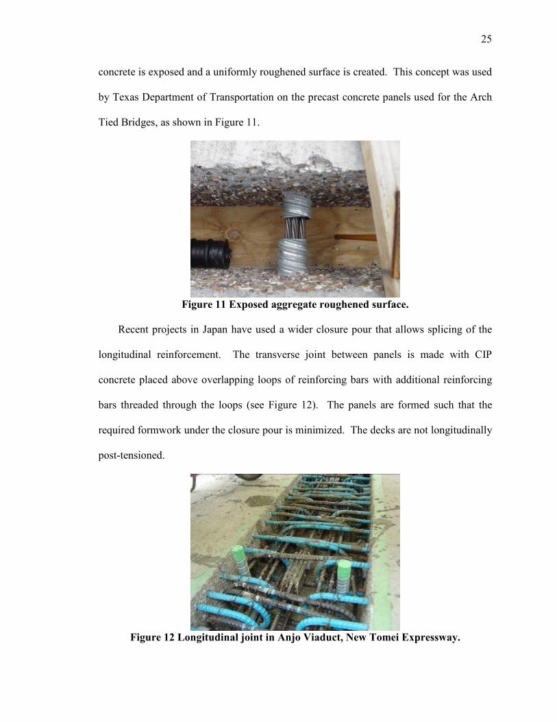
concrete is exposed and a uniformly roughened surface is created. This concept was used
by Texas Department of Transportation on the precast concrete panels used for the Arch
Tied Bridges, as shown in Figure 11.
Figure 11 Exposed aggregate roughened surface.
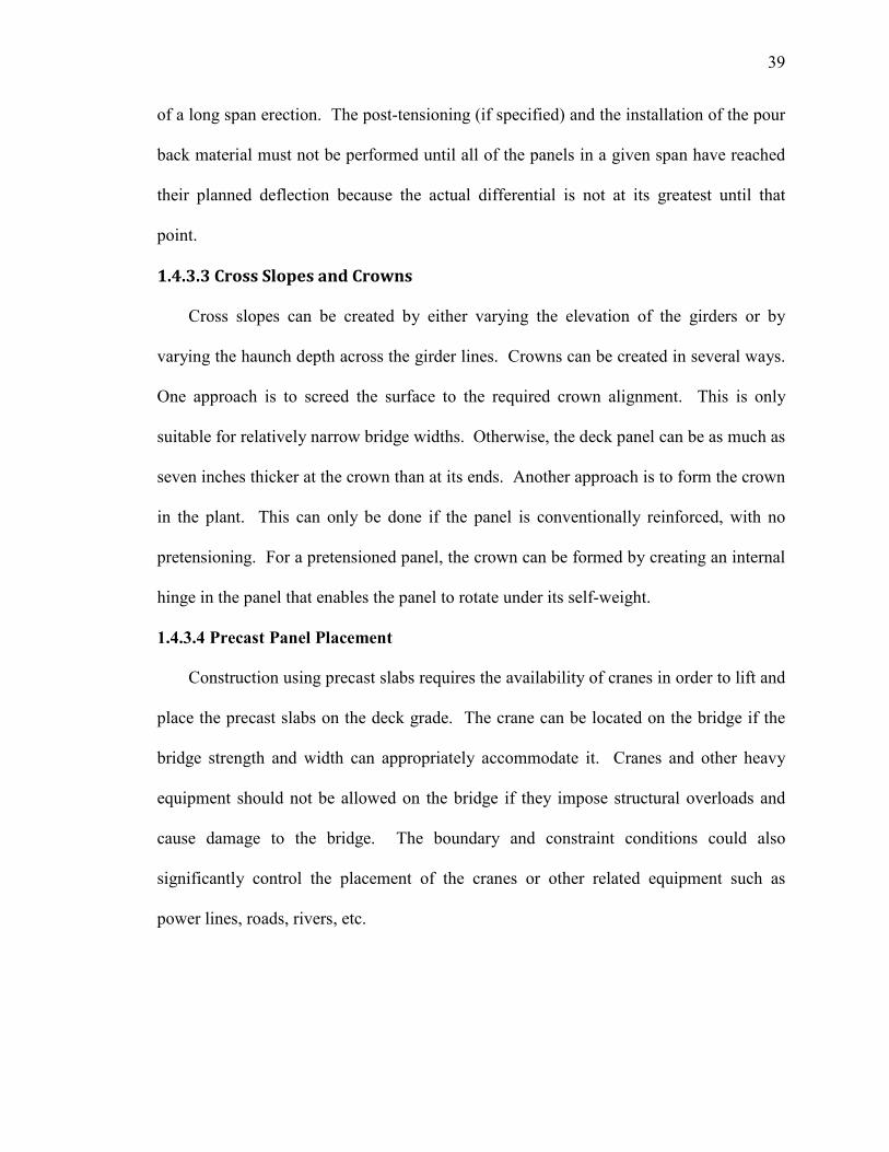
Recent projects in Japan have used a wider closure pour that allows splicing of the
longitudinal reinforcement. The transverse joint between panels is made with CIP
concrete placed above overlapping loops of reinforcing bars with additional reinforcing
bars threaded through the loops (see Figure 12). The panels are formed such that the
required formwork under the closure pour is minimized. The decks are not longitudinally
post-tensioned.
Figure 12 Longitudinal joint in Anjo Viaduct, New Tomei Expressway.

26
1.3.3 Longitudinal Reinforcement
Longitudinal reinforcement in deck slabs is used to distribute the concentrated live
load in the longitudinal direction. It is also used to resist the negative live load bending
moment at the intermediate supports for continuous span bridges. Longitudinal
reinforcement can be mild or prestressed. For deck slabs made with full-depth precast
panels, splicing this reinforcement at the transverse joint between panels is a challenge
for design engineers because:
1. The panel has relatively short length (from 8 to 12 feet); therefore, a long concrete
closure joint (2 to 3 feet) has to be used to lap splice the longitudinal
reinforcement. This requires wood forming from under the panels and an
extended period of time for curing.
2. The longitudinal reinforcement is spliced at the transverse grouted-joint between
panels, which is considered the weakest joint in the system. Therefore, great care
has to be taken in detailing the splice connection to maintain the construction
feasibility and avoid leakage at the joint during the service life of the deck.
3. Splicing the longitudinal reinforcement requires high quality control during
fabrication of the panel to guarantee that the spliced bars match with very small or
zero tolerance.
4. Splicing the longitudinal reinforcement requires creating pockets and/or
modifying the side form of the panel, which increases the cost of panel
fabrication.
As a result, a few highway agencies, such as Alaska Department of Transportation
(ADOT) and New Hampshire Department of Transportation (NHDOT), have opted not to

27
splice the longitudinal reinforcement for simply supported span bridges. A non-
reinforced transverse joint on the precast deck system has recently been used on Dalton
and Pedro Creek Bridges on Route FAP 65 in Alaska. Although ADOT design engineers
have reported that there is neither significant cracking nor leakage at the joints, the reader
should note that the average daily traffic on these bridges is very low compared to
bridges built in metropolitan cites.
The majority of highway agencies prefer to provide some type of reinforcement
across the transverse joints. This section describes various methods that have been used
in the past to provide and splice the longitudinal reinforcement, either mild reinforcing
bars or post-tensioning tendons.
1.3.3.1 Mild Longitudinal Reinforcement
Several methods have been utilized for splicing mild longitudinal reinforcement.
These include:
1. A lap splice detail was used in the full-depth precast concrete deck panel system
for the deck rehabilitation project of bridge C-437 carrying US-189 over I-80 to
Wanship, Utah. Note that the design engineer allowed the use of a threaded
coupler at the face of the transverse joints to simplify the side forms used in
fabrication. Figure 13 shows a similar detail.
2. U-shaped pin bars have been used successfully in Japan and Europe. Figure 12
shows an example of the overlapping U-shaped bar splicing method.
A spiral confinement detail has been developed to reduce the lap splice length and
give higher construction flexibility of the splice connection (Babaei, Fouladgar, &
Nicholson, 2001). Figure 14 shows the splice connection where a high strength spiral

28
confines a loose bar. This detail reduces the lap splice length by about 40 to 50 percent
and simplifies the fabrication of the panel because no bars extend outside the transverse
edges of the panel.
Figure 13 Straight-splice closure pour detail.
Figure 14 Panel-to-panel connection using spiral reinforcement.
1.3.3.2 Longitudinal Post-tensioning
Longitudinal post-tensioning has been used on the majority of bridges built with full-
depth precast panels during the last 30 years. It puts the transverse panel-to-panel joints

29
under compression, which can eliminate the tensile stress resulting from live load.
Longitudinal post-tensioning is typically applied after the transverse panel-to-panel joints
are grouted and have gained adequate strength, and before the panel-to-girder connection
is locked. This procedure guarantees that all of the post-tensioning force is applied to the
precast deck.
In many deck panel projects, high strength threaded rods or high-strength strands in
flat ducts are uniformly distributed between girder lines. The tendons are fed inside ducts
that are provided in the panel during fabrication. Longitudinal post-tensioning can be
provided in stages and coupled as shown in Figure 15. After the tendons are post-
tensioned and secured, the ducts are grouted with non-shrink grout to protect the tendons
from corrosion.
Where coupling of longitudinal post-tensioning is necessary, proper detailing of
ducts, anchorage zones, and blockouts is essential to the constructability and performance
of the system. Figure 16 shows details of a precast slab where the duct is coupled but the
tendon is not required to be coupled.
Longitudinal post-tensioning reinforcement concentrated at girder lines has been
used on the Skyline Drive Bridge in Omaha, Nebraska. Figure 17 shows a view of the
bridge at a girder line. There is a continuous open channel along the girder line into
which the longitudinal post-tensioning strands are threaded as shown in Figure 18. The
post-tensioning reinforcement comprises 16 - ½ inch, 270 ksi low relaxation strands. The
strands are fed in the open channels created over the girder lines and into a special end
panel that houses the anchorage device as shown in Figure 19.

30
Figure 15 Post-tensioning detail used on Bridge-4 constructed on Route 75,
Sangamon County, IL.
Figure 16 Typical layout of sheath ducts across the transverse joint.
Figure 17 Open channel over girders for longitudinal post-tensioning on the Skyline
Drive Bridge, Omaha, NE.
Duct
Grout Valve
Grout Tube
Grout Tube Coupler
Duct
ThreadedRod
Leveling PlateStandard Coupler
Anchor Bolt
Anchor Plate
Elevation View
Plan View
B1 B1
Pocket B1
Pocket B1
Lower Lip

31
Figure 18 Strands in position in channel over girder on Skyline Bridge.
Figure 19 Special anchorage device in end panel of Skyline Bridge.
1.3.4 Longitudinal Joints
Longitudinal joints are used when the deck cross-section width forces the weight and
size requirements of available cranes to split the deck panels down the length of the
bridge. The cost of introducing longitudinal joints should be compared with crane
capacity when bridge cross-sections exceed 50 feet. Bridges carrying three or more lanes
of interstate traffic should consider using longitudinal joints with full-depth precast
concrete deck panel construction. Longitudinal joints are also required in instances
where bridge traffic can never be detoured or closed. The location of the longitudinal

32
joint also serves as the staged construction line in order to move traffic through the work
zone.
The longitudinal joint has been located and designed using two different approaches.
The first is to leave an open strip, between the deck panels, that is subsequently cast with
concrete. The exact strip width is determined by the lap splice requirements of the
transverse mild steel reinforcement that is spliced between the adjacent deck panels. This
open strip is usually located over a girder in order to use its top flange to support the
bottom form, and to minimize shear force across the joint. Therefore the lap splice
carries the full negative moment of the bridge deck over the joint.
The second configuration is to use a similar female-to-female detail as used in the
transverse joints. There is no space to splice reinforcement between panels, so the joint is
post-tensioned after it is filled with high-strength non-shrink grout. This joint can be
located between the girders, such that the full positive moment of the deck is carried over
the joint. The post-tensioning improves the shear resistance of the joint. If the joint
opens because of live load, it will open on the bridge deck’s bottom surface, thereby
minimizing salt and water intrusion from the top surface above. Although this
configuration is more expensive, it should reduce crack openings on the top surface of the
deck that would result over the girders and create a more durable system.
1.3.4.1 Longitudinal Joint Design
Longitudinal joint design uses the same methodology as that for structural design
transverse to the bridge centerline, whether the loads are carried by conventional
reinforcement or by post-tensioning the joint. The unique features of this design result
from the effects of construction and traffic sequence on the panel and joint. For

33
longitudinal joints—over girder lines—that are reinforced with conventional
reinforcement, deck design should account for a barrier crash load at the joint due to
installation of a temporary barrier if the bridge is constructed under traffic. For
longitudinal joints—between girder lines—that are reinforced with conventional
reinforcement or post-tensioning, deck design should account for a barrier crash load to
the joint before joint reinforcing is installed. Also, design consideration must be given to
the cantilevered portion of the deck.
When longitudinal joints are post-tensioned, the post-tensioning should be designed
to prohibit cracking from tension forces due to service loads. This requirement affects
the amount of post-tensioning force across the joint, as well as the required depth of the
deck.
When longitudinal joints are conventionally reinforced, the joint width must be sized
to develop the bars entering the joint from each panel. The joint width can be reduced by
using standard hooks on the bars entering the joint and/or spiral reinforcement to confine
the reinforcement. Detailing of the longitudinal joint must accommodate the proposed
sequence of construction and traffic staging. If the longitudinal joint is post-tensioned
while one adjacent panel carries traffic, then a coupling device may be used to post-
tension the panels in stages in order to carry live loads during a traffic stage.
1.4 PRODUCTION, HANDLING, AND CONSTRUCTION
Full-depth precast concrete bridge deck panels are practical alternatives to site cast
concrete bridge decks in many situations. This system promotes shorter construction
time for new and replacement bridge projects. The effectiveness of the construction
increases with the length of the bridge; additionally, the efficiency increases with the

34
traffic volume using the bridge because the accelerated construction provides open travel
lanes much faster than CIP construction. State DOT’s and the Federal Highway
Administration (FHWA) are now looking at the design/build process where the low bid is
just one concern. Contractors and designers also focus on innovation and speed of
construction in their design/build proposals.
The precast concrete deck panel is providing the industry with a new solution. The
use of full-depth precast bridge deck panels is shortening construction time while holding
the standard for quality, modernization, and long term durability.
1.4.1 Requirements for Production
There are a multitude of quality control checks to be considered during the
production of full-depth precast panels. These include: (1) location and alignment of
post-tensioning ducts, (2) deck thickness must satisfy cover requirements, (3) positioning
and rigidity of the transverse shear key, (4) uniformity of the surface finish, (5) influence
of shrinkage, creep, and camber on the final alignment, (6) location of attachments for
traffic barrier service, (7) location and coordination of the shear pocket positioning with
respect to the existing or proposed girder alignment, and (8) accurate location of lifting
hardware for handling and placement of the panels. These items must be addressed in the
development of shop drawings and the set up of form work, and then routinely verified in
the pre-pour inspection phase of casting as well as during the post-pour inspection.
Concrete should not be deposited in the forms until the engineer has inspected and
approved the placement of ducts, anchorages, and all other materials in the slabs and
marked his approval on each item (Precast Prestressed, 1987; Tadros & Baishya, 1997).

35
Methods for lifting the deck panels are shown on the shop drawings. Any metal
apparatus in the panel should be recessed at least two inches, cut off flush with the
surface of the recess, and the recess grouted flush with the deck surface. Tolerances for
casting the slabs should be included especially in the location where the longitudinal
post-tensioning ducts are present. The ducts are oversized to accommodate the specified
tolerances. The precast concrete slabs are normally fabricated to plan dimensions within
the tolerances listed below (Tolerances for Precast, 2000):
Width ................................................................................................... ± ¼ in. [± 6mm]
Length .................................................................................................. ± ¼ in. [± 6mm]
Depth ............................................................................... +¼ in., -⅛ in. [+6mm, -3mm]
Variation from specified plan end squareness or skew ....................... ± ¼ in. [± 6mm]
Precast slab sections could be subject to rejection on account of failure to meet any
of the specification requirements. In addition, individual sections may be rejected when
any of the following defects are identified:
1. Fractures or cracks that, in the opinion of the engineer, will hinder the
performance of the member.
2. Defects that indicate imperfect proportioning, mixing, or molding.
3. Surface defects indicating honeycombing or open texture.
4. Damaged or cracked ends, where such damage would prevent the construction of
a satisfactory joint.
1.4.2 Handling
The loads and forces on the precast and prestressed slabs during fabrication,
transportation, and erection require separate analyses because the support points and

36
orientation are usually different than when the panel is in its final position. Several
factors must be considered to select the most feasible manner of furnishing the concrete
panels for a project (Babaei et al., 2001). These factors can be summarized as follows:
1. Stability and stresses on the concrete element during handling.
2. Transportation size, weight regulations, and equipment restrictions.
3. Available crane capacity and rigging at both the plant and the project site.
Position of the crane must be considered, since capacity is a function of reach.
Improper jobsite handling and storage, of the relatively thin prestressed sections
required for modular bridge deck construction or replacement, can lead to dimensional
instability, cracking, or warping that will adversely impact the panels’ suitability for
placement in the new superstructure. The contractor should be directed by
representatives from the prestress supplier in regard to proper lifting techniques as well as
blocking configurations necessary if jobsite storage will be required prior to slab
installation. If jobsite storage is required, the site should be carefully chosen and set up
so that varying weather conditions do not lead to settlement problems. Once the initial
dunnage bedways are set up, periodic elevation checks should be performed for
verification that no settlement problems have occurred. Special attention must be given
to irregularly shaped pieces or any section that might have a post-casting induced crown.
1.4.3 Construction Operations
The contractor is normally responsible for all traffic conditions related to the
performance of operations including, but not limited to, such conditions as delays, back-
ups, congestion, and reduced flow. Construction operations should be scheduled so that

37
interference with the normal movement of traffic is kept to a minimum (Abendroth, 1995;
Slavis, 1983; Tadros & Baishya, 1997).
1.4.3.1 Installation of Shear Connectors
The method for installing shear connectors is dependent on the type of construction
and the type of girder. For new bridge deck construction on steel girders, it is most
common to use steel shear studs that are prefabricated on the girder before delivery to the
construction site. Shear studs may also be welded to the steel girders on-site. For new
bridge deck construction on concrete girders, it is common to use the girders’ shear
reinforcement, which is extended up from the web and bent horizontal, for the horizontal
shear reinforcement. On rehabilitated bridges, the existing shear reinforcement is cut off
prior to new shear connector installation. Shear studs are field welded to the existing
steel girders in the location of the panels’ shear pockets. In a paper by Issa, Salas, &
Hameed, (2005) that has been submitted for possible publication to in the PCI Journal,
shear stud bolts can be attached to concrete girder flanges by drilling a hole in the
existing girder, epoxy filling the hole, inserting the bolt in the hole, and allowing one day
for the epoxy to cure.
1.4.3.2 Field Engineering Prior to Slab Installation
Regardless of the method used for elevation control and temporary slab support,
girder deflection issues must be carefully considered. When the construction allows
complete spans of deck panels to be erected, post-tensioned, and grouted in a continuous
operation, the deflection accommodation is relatively simple. The top-of-girder
elevations are determined and all of the support angles for that span are set and checked
prior to the setting of any deck panels. If leveling bolts are used, instead of support

38
angles, the procedure is the same except that dimensions are marked on the girders for the
amount of bolster height required for each panel corner. The important concept here is
that all of the top-of-girder elevations are determined prior to the setting of any panels, so
that the full theoretical dead load deflection information can be applied to the setting
height of the panels. It should also be noted that the top-of-panel elevations will not be as
planned until all of the panels have been installed in the span, since the planned dead load
deflection is based on a fully decked span.
In a rapid deck replacement project, where long spans may not be completely
replaced in a continuous operation and traffic is to be maintained during non-working
periods, the deflection accommodation is somewhat more difficult. The deflection
accommodation becomes a “balancing act” between the dead load of the portion of the
existing deck which remains, the dead load which has been removed because of the
partial existing deck demolition, and the anticipated deflection due to the installation of
the new deck panels. The field engineer would have to be aware of the amount of
deflection that would be expected to occur as the remaining panels in a given span were
erected, and add that amount of deflection to the theoretical setting elevation of the
current panel. Essentially, the field engineer has to be aware of where the span is in the
development of its dead load deflection at any point during the erection process. While
the setting elevation of the last several panels in a span might be relatively equal to their
finished elevation, the setting elevation of the first several panels might be considerably
higher than their elevation after all of the remaining panels in that span are erected.
Where differential deflection is anticipated between interior and exterior girders, it is
also necessary to compensate for deflection that has yet to occur during the early stages
39
of a long span erection. The post-tensioning (if specified) and the installation of the pour
back material must not be performed until all of the panels in a given span have reached
their planned deflection because the actual differential is not at its greatest until that
point.
1.4.3.3 Cross Slopes and Crowns
Cross slopes can be created by either varying the elevation of the girders or by
varying the haunch depth across the girder lines. Crowns can be created in several ways.
One approach is to screed the surface to the required crown alignment. This is only
suitable for relatively narrow bridge widths. Otherwise, the deck panel can be as much as
seven inches thicker at the crown than at its ends. Another approach is to form the crown
in the plant. This can only be done if the panel is conventionally reinforced, with no
pretensioning. For a pretensioned panel, the crown can be formed by creating an internal
hinge in the panel that enables the panel to rotate under its self-weight.
1.4.3.4 Precast Panel Placement
Construction using precast slabs requires the availability of cranes in order to lift and
place the precast slabs on the deck grade. The crane can be located on the bridge if the
bridge strength and width can appropriately accommodate it. Cranes and other heavy
equipment should not be allowed on the bridge if they impose structural overloads and
cause damage to the bridge. The boundary and constraint conditions could also
significantly control the placement of the cranes or other related equipment such as
power lines, roads, rivers, etc.

40
1.4.3.5 Placement of CIP Pour Back Material
It is important to exercise care in the placement of the chosen material required for
the pour back areas. Exposed areas of slabs to be incorporated in the pour back area
should be sandblasted at the prestresser’s yard prior to shipment and water-blasted in the
field just prior to installation of the pour back material. Water blasting removes any
deleterious material encountered since the sand blasting, and properly moisture
impregnates the exposed surfaces for bonding with the pour back material.
It is very important to prevent premature moisture loss and maintain adequate
temperature during the curing period; however, it much less troublesome than trying to
cure an entire overlay. The objective here would be to utilize a material with a curing
period in the range of hours and not days, so that traffic could be placed on it the
following morning. The profile grinding would not be performed until the end of the
project after all of the superstructure had been installed.
1.4.3.6 Post-Tensioning
After the panels are set into position and leveled, the post-tensioning ducts between
panels are mechanically connected and sealed water tight. It should be clearly stated in
the specifications if construction equipment or vehicles are allowed on the precast deck
slabs prior to completion of the post-tensioning process (Issa, Idriss, Kaspar, & Khayyat,
1995). The transverse panel joints are to be poured and allowed to cure.
Once the concrete or grout between the precast slabs has attained the required
compressive strength (typically 4,000 psi), the longitudinal post-tensioning tendons can
be tensioned. The duct, post-tensioning threaded bars and/or strands, and other
components need to be completely free from oil, grease, and foreign material. The

41
tendons are then installed, stressed, and grouted to a pressure of 150 psi. This process
provides the post-tensioning steel with multiple layers of required corrosion protection
for the longer structural life spans now being required for new and rehabbed bridge
structure projects. Two layers of corrosion protection are required for the stressing steel
and the concrete in the panel is not considered a layer of corrosion protection. The two
layers of corrosion protection are: (1) the water proof duct and (2) the non-shrink, zero
bleed grout within the conduit totally encapsulating the post-tensioning steel.
After post-tensioning and grouting the tendons, the panels’ shear pockets are to be
grouted to allow the deck slabs to become composite with the girders. This construction
sequence allows the post-tensioning stresses to distribute through the slab without undue
losses being transferred into the shear studs. Post-tensioning losses through the shear
studs can only be avoided when the slabs are post-tensioned prior to pouring the shear
stud pockets.
1.4.3.7 Construction Periods
One major advantage of rapid deck construction or replacement is the minimized
impact to the traveling public. Arguably the worst time to impact the average motorist is
the period of time when a person is either traveling to or heading home from work.
When a deck replacement involves an existing substructure, weekend closures would
be the least disruptive to the traveling public and most productive for the contractor. Six
and three quarter–eight hour shifts could be worked between midnight on a Friday and
6:00 a.m. Monday morning. When an existing substructure is to receive a new
superstructure, the existing superstructure must be demolished. The task of protecting
existing girders where necessary and removing the existing deck and barrier service could

42
well be the most time consuming stage of the entire operation. It is feasible that the first
several shifts of the weekend cycle would be devoted entirely to demolition and removal
operations, with the remaining several shifts earmarked for installation, post tensioning,
and pour back installation of the new prestressed superstructure.
Demolition operations are an integral portion of the big picture when contemplating
the rapid replacement of an existing bridge deck. A lesser number of long duration (full
weekend) bridge closures is often preferred over a greater number of short duration
(single night, or day time) lane closures.
1.5 WEARING AND PROTECTION SYSTEMS
When using full-depth precast bridge deck systems, bridge engineers and owners
generally agree they need to provide a smooth riding surface and protection against the
intrusion of chlorides. The most commonly used deck wearing and protection systems
are the thin bonded hydraulic cement concrete overlay and the waterproof membrane
overlaid with asphalt concrete. Other systems that have been successfully used on site
cast concrete bridge decks include a thin epoxy concrete overlay, monolithic cast
increased cover over the reinforcement, and low permeability concrete. The latter three
wearing and protection systems have been found to save considerable time and money
over the first two systems mentioned.
Problems related to the corrosion of reinforcing steel and consequent spalling and
delamination in reinforced concrete decks are considerably intensified by the use of
deicing chemicals. As a result, protective overlays are being employed in many states as
part of rehabilitation and corrosion protection strategies. The overlay provides a wearing
surface and protects the precast sections from deicing materials.

43
The overlay surface should be well bonded and crack free to protect the underlying
segments. It is intended that the overlay be removed and replaced when it becomes
loaded with chloride ions from deicing salt or if extensive cracking or delamination
occurs. The best surface preparation technique is the use of water jet blasting for latex-
modified concrete (LMC) and microsilica concrete (MSC) and sandblasting or shot
blasting for thin epoxy bonded overlays.
Application of overlays on bridge decks can fulfill three design functions: 1) they
can strengthen the structure in terms of stiffness and increased cover against further
deterioration due to corrosion and fatigue cracking, 2) improve smoothness and restore
ride quality, and 3) add skid resistance.
1.5.1 Methodology for Determining Overlay
Sprinkel (2003) investigated deck wearing and protection systems used on bridges
constructed with precast concrete deck panels. Information on the design, construction
steps, cost, and performance of the systems was obtained. Wearing and protection
systems selected for comparison included the thin bonded hydraulic cement concrete
overlay, waterproof membrane overlaid with asphalt, thin bonded epoxy concrete
overlay, monolithically cast concrete overlay, and low permeability precast concrete deck
panel.
Sprinkel (2003) compiled cost data based on bid tabulations in Virginia between
1999 and 2002 and compared the deck wearing and protection systems. The data was
obtained from the Virginia Department of Transportation bridge office in Richmond,
Virginia. The data is for wearing and protection systems used on many types of bridges
with concrete decks (CIP concrete on beams, prestressed box beams, prestressed slabs,

44
post-tensioned segmental, etc.). While the cost of a wearing and protection system varies
with location, access, bridge design, and material quantity, the relationships between the
costs of the systems should reasonably approximate most situations.
A sketch of the five systems is shown in Figure 20 with construction steps for the
five systems shown in Table 2. Average cost data based on bid tabulations in Virginia is
shown in Table 3 along with life cycle cost estimates (based on an assumed 30 year life
cycle). A zero interest rate was used in the life cycle cost estimates.
The service life of a deck wearing and protection system is the piece of information
that is necessary for a life cycle cost analysis. Unfortunately, reaching a consensus on
service life is difficult if not impossible. Consequently, the service life values used to
compare the deck protection systems (shown in Table 3) are estimates that come from
approximate life expectancy averages.
Table 2 Construction steps for wearing and protection systems.
Strategy Construction Steps Total
Steps
Thin Bonded Concrete Overlay
Install Slabs, Grind Surface, Shot blast Surface, Place Concrete Overlay, Cure Concrete Overlay, Groove Surface
6
Membrane/Asphalt Overlay Install Slabs, Grind Surface, Place Membrane, Place Asphalt 4
Thin Bonded Epoxy Overlay Install Slabs, Grind Surface, Shot blast Surface, Place Epoxy Overlay
4
Monolithic Concrete Install Slabs, Grind Surface, Groove Surface 3 Low Permeability Concrete Install Slabs, Grind Surface, Groove Surface 3

45
Table 3 Cost of wearing and protection systems for precast deck slabs, $/yd (Babaei
et al., 2001).
Strategy Grinding Shot Blast Protection Skid Initial Life,
yrs.
Life
Cycle
Thin Bonded Concrete Overlay
6* 6 62 6 80 30 80
Membrane and Asphalt Overlay
6* 0 27 18 51 15 96
Thin Bonded Epoxy Overlay (15 yr. Life)
6 6 21 0 33 15 60
Thin Bonded Epoxy Overlay (30 yr. Life)
6 6 21 0 33 30 33
Monolithic Concrete (30 year life)
6 0 24 6* 36 30 36
Monolithic Concrete (90 year life)
6 0 24 6* 36 90 12
Low Permeability Concrete (90 year life)
6 0 0 6* 12 90 4
* If necessary

46
Figure 20 Wearing and protection systems include: (a) typical CIP deck (reference),
(b) bonded concrete overlay, (c) waterproof membrane overlaid with
asphalt, (d) epoxy overlay, (e) monolithic concrete overlay, (f) low
permeability panel with no overlay.
(a)
(b)
(c)
(d)
(e)
(f)
7"
7"
7"
7"
7"
7.5" CIP Deck w/ 2" cover & 0.5" W.S.
1/2" - 1" overdepth for grinding* if necessary
1/2" - 1" overdepth for grinding* if necessary
1/2" - 1" overdepth for grinding
1/2" - 1" overdepth for grinding
1/2" - 1" overdepth for grinding
1 1/2" - 2" bonded concrete overlay
2" asphalt overlay
waterproof membrane
1/4" epoxy overlay
2" monolithic concrete

47
1.5.2 Thin Bonded Concrete Overlays
The thin bonded concrete overlay system applies a two inch thick CIP concrete
overlay on top of the AASHTO standard two inch clear cover. This system may require
profile grinding before adding the overlay to remove any elevation differences in the
deck panels. Additionally, skid resistance is provided by saw cut grooves.
Thin bonded concrete overlays are the most expensive deck wearing and protection
system based on initial cost. Cost data indicate the average cost of a bonded concrete
overlay including grinding, surface preparation, and saw cut grooves is $80 per square
yard. Properly constructed, thin bonded concrete overlays can last 30 years or more.
Unfortunately, some overlays have cracked and delaminated and had to be replaced
before the bridge was opened to traffic. Good surface preparation, low shrink concrete
mixtures, and good curing are required for successful thin bonded overlays. Factors that
can contribute to premature delamination of the overlay include poor surface preparation,
use of mixture proportions with high shrinkage, use of thick overlays, early shrinkage
cracking in the overlay, and creep and shrinkage of the newly constructed superstructure.
1.5.3 Waterproof Membrane Overlaid with Asphalt
A waterproof membrane overlaid with asphalt is the second most expensive deck
protection system based on initial cost. Cost data indicate the average cost of a
membrane and asphalt, including grinding is $51 per square yard. The installed
membrane accounts for most of the cost. The approximate two inches of asphalt overlay
protects the membrane and provides skid resistance. As with the thin bonded concrete
overlay, profile grinding on this system may be necessary to remove surface
irregularities, prior to membrane installation.

48
A properly installed membrane and rut resistant asphalt are required for a successful
overlay system. The construction for this method is fairly complex and rutting and
shoving of the asphalt overlay can also be a problem. Replacement of the overlay every
15 years can be expected. The membrane typically has to be replaced when the overlay
is replaced. The initial cost of the asphalt overlay on membrane is about 64% of a
bonded concrete overlay but on a life cycle basis the cost is approximately 20% more
with two overlays and membranes placed over 30 years. By placing a thin intermediate
layer of asphalt on the membrane followed by a surface mix, the surface mix can be
replaced after 15 years without replacing the intermediate mix and the membrane. The
life cycle cost would be less if the asphalt overlay can be replaced without damaging and
replacing the membrane.
1.5.3 Thin Bonded Epoxy Concrete Overlays
The epoxy overlay is a deck protection system that has been successfully used for 27
years on conventionally reinforced CIP concrete bridge decks. The epoxy overlay has
been shown to prevent the infusion of the chloride ions and can be expected to provide a
skid resistant wearing and protection system on decks for 15 to 30 years depending on
traffic volume (Guide Specifications, 1995). The epoxy overlay should perform just as
well on precast deck systems. The system is easily applied. Following profile grinding,
two layers of epoxy and aggregate are placed on a shot blasted surface. The average cost
is $33 per square yard including grinding and shot blasting. It costs approximately 65%
of an asphalt overlay with membrane. An additional benefit of the epoxy overlay is that
it is only one-quarter inch thick and if spalling occurs it does not have a major impact on
the ride quality and repairs are easily made. By comparison, the spalling of an asphalt

49
overlay leaves a much deeper hole. The thin epoxy overlay is not prone to cracking and
delamination like the hydraulic cement concrete overlay. The epoxy overlay is flexible
and will not likely crack and delaminate over the joints between the deck panels.
AASHTO guide specifications for the thin bonded epoxy overlay were published in 1995
(Guide Specifications, 1995). For added protection, a layer of epoxy could be placed
over the joints between the panels prior to placing the epoxy overlay.
1.5.4 Monolithic Concrete Overlays
The monolithic concrete overlay wearing and protection system is another low cost
alternative to the conventional protection systems. The system involves casting an
additional two inches of concrete to the AASHTO minimum two inch cover at the time
the deck panels are cast. After all of the deck panels are installed, a diamond grinding
machine is used to correct surface irregularities and provide the final deck profile.
Grooves are saw cut for skid resistance. Good skid resistance is obtained when diamond
grinding is used to correct the profile of concrete pavements. Saw cut grooves are not
required. If the diamond ground surface is acceptable for concrete pavements it should
be acceptable for bridge decks. Elimination of saw cut grooves would save $6 per square
yard.
Based on the average cost of bridge superstructure concrete in Virginia of $438 per
cubic yard a two inch thick monolithic concrete overlay would cost approximately $24
per square yard. Diamond grinding and saw cut grooves would each add another $6 per
square yard for a total of $36 per square yard. The cost should be much lower because
only the materials’ cost increases as the overlay portion of the precast deck system is cast.
The monolithic hydraulic cement concrete overlay wearing and protection system can be

50
expected to protect the deck as long as or longer than a quality thin bonded hydraulic
cement concrete overlay. At 30 years, if the top two inches of the monolithic concrete
contains sufficient chlorides to warrant renewal and replacement, a thin bonded cement
concrete overlay can be placed at that time. However, because of the low permeability
that is achieved with today’s concretes that are prepared with low water to cement ratios
and pozzolans or slag, it is reasonable to expect that the monolithic concrete would not
contain sufficient chloride ions to warrant removal for more than 150 years (see later
discussion on low permeability concrete) (Ozyildirim, 1998). If the monolithic hydraulic
cement concrete is replaced at 30 years, (same age as the thin bonded concrete overlay)
the life cycle cost is 45% of that of a thin bonded concrete overlay. The monolithic
concrete overlay wearing and protection system has a lower risk of problems since the
concrete is cast onto the precast panels as they are fabricated. The problems with the
overlay delaminating and cracking are eliminated.
1.5.5 Low Permeability Concrete Deck Panel
This system utilizes a precast concrete deck panel cast from low permeability
concrete. The panel’s depth includes the AASHTO minimum two inch cover and
approximately one-half inch of sacrificial over depth concrete for surface grinding with
no additional overlay. The panel is then saw cut to provide skid resistance if it is
necessary.
Most reports on time to corrosion of reinforcement in decks are based on experiences
with older conventional bridge decks that were typically constructed with portland
cement and a water to cement ratio of 0.45 or higher. The low permeability concretes
currently being used to construct precast concrete deck panels have a significantly higher

51
resistance to the penetration of chloride ions and moisture than the concretes in older
decks. Mixtures with pozzolans and slag and water to cement ratios of 0.35 to 0.4 have
permeability to chloride ion that is approximately one-fourth to one-tenth that of mixtures
with portland cement and a water to cement ratio of 0.45 (Ozyildirim, 1998). The
diffusion constant for the conventional deck concrete was 5 x 10⁻⁸ cm2/sec. The diffusion
constants for the low permeability concretes were 0.2 to 1 x 10⁻⁸ cm2/sec (Ozyildirim,
1998). The diffusion constants for the low permeability concretes are approximately one-
fifth to one-twenty-fifth of that of the conventional deck concretes. Chloride corrosion
induced spalling could be expected in these older decks in 37 years (Py, Weyers, Weyers,
Mokarem, Zemajtis, Sprinkel, & Dillard, 2000). Precast deck systems constructed with
low permeability concrete (water to cement ratio of 0.35 to 0.4 and pozzolans or slag)
and free of cracks can expect to be free of chloride corrosion induced spalling for four to
ten times longer. Precast deck panels with low permeability concrete that are
pretensioned and/or post-tensioned and therefore free of cracks should not have chlorides
present in sufficient quantities to cause corrosion of reinforcement with a two inch cover
for nearly 150 years. The use of a protection strategy other than casting the precast deck
panels with low permeability concrete is difficult to justify for deck panels that are
pretensioned and/or post-tensioned.
1.5.6 Profile Grinding
One major advantage of profile grinding the final roadway surface to satisfy ride-
ability requirements is that weather issues do not come into play. Profile grinding
eliminates the weather, curing, workmanship, and ready-mix consistency issues
commonly associated with full surface overlays. Many states are presently utilizing

52
profile grinding to improve the ride-ability of existing rigid pavements. If the technology
were applied to new precast deck panels, extremely smooth riding surfaces would be
attained and seamless transitions would be made between panels across the CIP pour-
back areas. Generally, no further texturing should be required as the necessary skid
resistance is provided by the longitudinal “corduroy” type surface that is left after the
grinding operation. The micro-cracking that occurs during a typical “milling” operation
does not occur during profile grinding because the concrete is “wet-cut” with special
diamond blades and not fractured away with carbide inserts. A typical diamond profiling
machine weighs approximately 40,000 lbs and surfaces an area between 36 and 48 inches
wide per pass at one-quarter inch deep. A typical production rate for one machine would
be approximately 1,000 square yards per ten hour shift. The cost of profile grinding will
vary from between $4 to $15 per square yard because of geographic location. The
variance in price is primarily due to the hardness of the native coarse aggregate found in
different parts of the country. The harder the coarse aggregate, the higher the price.
1.5.7 Rapidly Constructed Wearing and Protection Systems
The low permeability concrete deck panel overlay option has no effect on
construction time and causes no traffic disruption because the concrete is ready for traffic
when the panels are installed. The monolithic concrete overlay wearing and protection
system has a negligible effect on construction time and on traffic disruption because the
surface only has to be diamond ground after the panels are installed. The grinding can be
done a lane at a time as traffic uses the other lanes. The thin epoxy overlay wearing and
protection system has minimal effect on construction time and traffic disruption because
the overlay can be installed with short lane closures during off peak traffic periods such

53
as at night. The waterproof membrane overlaid with asphalt concrete has more effect on
construction time and traffic disruption than the thin epoxy overlay but rapid installations
during off peak traffic periods such as at night can be done in many situations. The thin
bonded hydraulic cement concrete overlay has the most effect on construction time and
traffic disruption because of the time required for the concrete to cure. Rapid hydraulic
cement concrete overlays in which traffic is placed on the concrete after only three hours
of cure time have been successful (Sprinkel, 1982). The overlay is constructed with
latex-modified concrete that is batched with special rapid hardening hydraulic cement.
2.0 NUDECK SYSTEM
The NUDECK is an innovative full-depth precast concrete bridge deck system that
provides fast and efficient construction, superior performance, and low long-term
maintenance and replacement costs. Bridge deck deterioration is diminished with the
combination of high performance precast concrete and two-way prestressing that reduces
creep, shrinkage, and cracking. In addition, NUDECK panels are installed, post-
tensioned, and connected to bridge girders in a significantly shorter duration than
conventional decks due to the elimination of deck forming, reinforcing, curing, and
stripping operations.
2.1 SKYLINE BRIDGE DECK
The first generation of the NUDECK system was implemented on the Skyline Bridge
in Omaha, Nebraska, which was completed in 2003 (See Figure 21). This project
received the 2004 PCI Award of Innovation Design and resulted in very reasonable cost
per square foot of the deck panels. The bridge consists of two spans, 89 ft and 125 ft, a
25o skew, and 55 in. deep steel girders spaced at 10 ft-10 in. (see Figure 22). The precast

54
bridge deck consists of twenty-six typical panels, with a width of 7.0 ft and a length
identical to the bridge width, and two end panels, which house the post-tensioning
anchorage block. The panel is 6 in.-thick with 2 in. Type K cement overlay. The concrete
strength of the panel is 4,300 psi at release and 6,000 psi at service. The precast bridge
deck panels are pretensioned transversely and post-tensioned longitudinally. 16-0.6 in.
strands are tensioned along each continuous 12 in.-channel over girder line.
Figure 21 Implementation of NUDECK Bridge Deck Panel System.

55
Figure 22 Skyline Bridge before Deck Erection.
Figure 23 shows the NUDECK system and highlights some of its unique features as it
was implemented on the Skyline Bridge (Tadros, 2004). The steel girders had 1.25 in.
studs arranged in a single row over the steel girder web at a spacing of 6 in., rather than
several rows of the smaller 3/4 in. or 7/8 in. studs. The bridge skew and the requirement
for a sidewalk on one side made the deck panel geometry relatively challenging,
especially that a requirement for a crown at the roadway centerline and a 2% cross slope
was enforced.
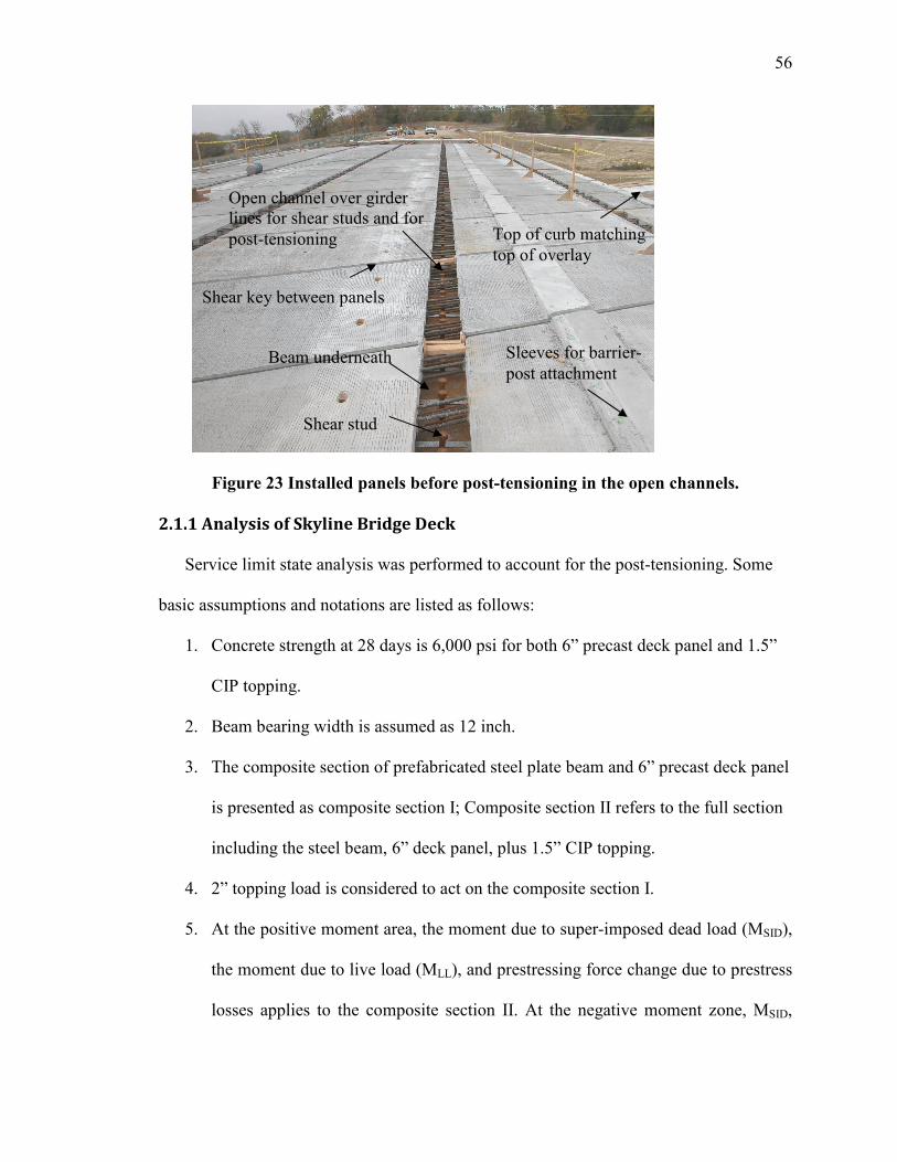
56
Figure 23 Installed panels before post-tensioning in the open channels.
2.1.1 Analysis of Skyline Bridge Deck
Service limit state analysis was performed to account for the post-tensioning. Some
basic assumptions and notations are listed as follows:
1. Concrete strength at 28 days is 6,000 psi for both 6” precast deck panel and 1.5”
CIP topping.
2. Beam bearing width is assumed as 12 inch.
3. The composite section of prefabricated steel plate beam and 6” precast deck panel
is presented as composite section I; Composite section II refers to the full section
including the steel beam, 6” deck panel, plus 1.5” CIP topping.
4. 2” topping load is considered to act on the composite section I.
5. At the positive moment area, the moment due to super-imposed dead load (MSID),
the moment due to live load (MLL), and prestressing force change due to prestress
losses applies to the composite section II. At the negative moment zone, MSID,
Open channel over girder lines for shear studs and for post-tensioning
Shear key between panels
Beam underneath
Shear stud
Sleeves for barrier- post attachment
Top of curb matching top of overlay
57
MLL, and prestressing force change are assumed to act on the composite section I
in case that the 2” topping cracks.
The bearing face section is most critical in terms of service limit analysis. The
negative moment at the bearing face, x = 88.6 ft of span 1, is -1944 kips-ft due to live
load. The table gives the sum of stresses due to various force components for each section
at service limit state. At the bearing face section, the total stress at the top fiber of
composite section II (the top fiber of 1.5” topping) may be calculated as follows:
MSID = 505.3 kips-ft
0.8MLL = 1944(0.8) = 1555.2 kips-ft
The elastic section modulus of composite section II, Stc = 6180.3 in.3
ftc (due to MSID) = MSID/(NStc) = )3.6180(6
)12(3.505= 0.164 ksi (tensile)
ftc (due to MLL) = MSID/(NStc) = )3.6180(6
)12(2.1555= 0.503 ksi (tensile)
ftc (due to prestressed force change) = 0.07 ksi (tensile)
ftc (total) = 0.737 ksi (tensile) > fcr = 0.581 ksi
Therefore, the top fiber of the 1.5” topping at the bearing face section will crack.
Conservatively, the properties of composite section I may be used for stress calculation,
which results in a total stress of 0.25 ksi (tensile) at the top fiber of the 6” precast panel
and less than fcr value. Thus, no crack will occur in the precast deck panel and there is no
need to worry about steel corrosion for this system. Note that most of the sections along
the bridge spans are in compression at service limit state, which indicates the proposed
system has the required high structural performance.

58
2.1.2 Skyline Bridge Deck Production
The precast panels were produced in Concrete Industries Inc., in Lincoln, NE. Figure
24 shows a typical precast deck panel reinforcement setup, which includes 4 pairs of 0.5
in. diameter pretensioning strands along the panel width (bridge transverse) direction.
The conventional reinforcement consists of 8 #7 continuous bottom bars, 8 #7 short top
bars across the open channel, and #5 rebar at 12”spacing as the secondary reinforcement.
Also provided are the spirals at ends of pretensioning strands for confinement and for
reduced demand of strand development length.
Figure 25 presents the details to create the panel crown. Note that some minor
modifications have been made in comparison with the demonstration panels to facilitate
the panel production (see Figure 26). It normally takes one day to set up the deck panel
reinforcement and the concrete is cast the next day. After the deck panel is poured and
concrete hardens, it may be lifted out of the prestressing bed. The crown is then formed
(see Figure 27 and Figure 28). The panel was put on the steel supports which gave a 2%
crown (see Figure 29). Afterwards, the top steel plate was removed and foam blocks were
taken out. Once the top strands are cut, the panel will deflect following the supports’
elevation and 2% crown be formed accordingly. Figure 30 illustrates the crown panels
stacked up in the precast yard.

Figure 24
Figure
Figure
24 Reinforcement Setup of Skyline Bridge Panel
Figure 25 Details of Crown Panel Forming.
Figure 26 A Close View of Crown Forming Detail.
59
Reinforcement Setup of Skyline Bridge Panel.

60
Figure 27 Pouring the Precast Deck.
Figure 28 Skyline Bridge Panel Handling.
Figure 29 Forming Crown.

61
Figure 30 Crown Panels Stacked Up in the Precast Yard.
2.1.3 Skyline Bridge Panel Handling and shipping
To avoid any buckling of the #7 bars across the open channels, the lifting points were
carefully determined. Figure 31 shows a possible lifting scheme considering the deck
panel is subject to its self-weight of 1.02 kips/ft. Accordingly, the moment diagram is
given in Figure 32, in which the bending moment values at the open channel locations are
nearly zero. Special steel frames were made to ship the precast panels (see Figure 33).
Note that it is desirable if the gap between adjacent steel frames can be minimized so that
the corresponding positive moment in the panel can be reduced.
15.87'
56.87'
18'3'
w = 1.02 kips/ft (Typ.)
17'
Channel location (Typ.)
3'
Figure 31 Panel Lifting Location Determination.

62
Figure 32 Moment Diagram due to Lifting.
Figure 33 Skyline Bridge Panel Shipping.
2.1.4 Support System
Prior to panel erection, an appropriate support system must be decided as to provide
the required bridge elevation. Three possible support systems are presented herein.
1) Option A
As shown in Figure 34, this support system consists of steel plate A (20”x6”x1/2”),
steel angle B (8”x4”x1/4”), and stiffener C (4”x4”x1/4”). Steel plate A is put on plastic
shims across the post-tensioning channel. Plastic shims can be placed over the steel girder
top flange and may be adjusted to meet the demanded bridge profile. An 8 in.-long steel
angle supports the adjacent panels at their corners along the channel direction. Stiffeners
may be provided at the middle of the steel angle as needed.
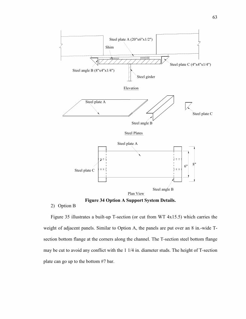
63
Steel angle B
Steel plate A
Steel plate A (20"x6"x1/2")
Steel angle B (8"x4"x1/4")
Steel girder
Shim
Elevation
Steel plate A
Steel angle B
Steel Plates
Steel plate C
Plan View
Steel plate C (4"x4"x1/4")
Steel plate C
6" 8"
Figure 34 Option A Support System Details.
2) Option B
Figure 35 illustrates a built-up T-section (or cut from WT 4x15.5) which carries the
weight of adjacent panels. Similar to Option A, the panels are put over an 8 in.-wide T-
section bottom flange at the corners along the channel. The T-section steel bottom flange
may be cut to avoid any conflict with the 1 1/4 in. diameter studs. The height of T-section
plate can go up to the bottom #7 bar.

64
T-section Plate
Elevation
Shim
Steel girder
Built-up T-section or Cut from WT4x15.5
22"
4"
8"
Figure 35 Option B Support System Details.
3) Option C
Option C is the support system used in Skyline Bridge. It has continuous steel angles
seated against the steel beam top flange. The interior beam has steel angles on both sides
of its top flange while the exterior beam has steel angles only on its interior side. Separate
strips cross the beam top flange and connect the steel angles (see Figure 36). The angles
should be strong enough to carry the precast panel weight before the open channels are
grouted.

65
Figure 36 Support System in Skyline Bridge.
2.1.5 Construction of Skyline Bridge Deck panel
2.1.5.1 Bridge Deck Post-tensioning Procedures
1. Pull the strands through the post-tensioning channel. Provide a minimum of 60 in.-
long strand projection beyond the bridge floor at each end. Check that no strands are
intersected or inter-wound.
2. Lodge the jaws in the “dead end” chucks with a light hammer. Use of excessive force
may break the jaws.
3. Tension all the strand to 11.7 kips regardless of sequence. This force corresponds to a
pressure of 1,500 psi on the pump gauge. Check again that no strands are intersected
or inter-wound.
4. At the tension end, mark a point on each strand surface at a distance, say, 36 in., away
from a fixed face, say the end anchorage. Call it Point A.
5. Tension the strand to the final force of 38.9 kips (5,000 psi on the pressure gauge).
Measure the displacement of Point A from 36 in. to (36 in. + X). Record X. The
quantity X should be = 11.5 in. A tolerance of ± 0.5 in. on the 11.5 average value is

66
acceptable. If the value of X and the gauge pressure do not match the values shown,
post-tensioning should stop and the engineer should be consulted.
6. If required by the owner, a check of the strand tension at the dead end may be
performed by measuring the pressure required to begin a very small, say 0.25 in.
elongation of the strand. That pressure must be equal to 5,000 psi less an allowance
for friction, anchorage seating and slab shortening losses. A 10% loss is reasonable.
2.1.5.2 Commentary of Post-tensioning Procedures
1. In Step 3, 11.7 kips is 30% of the final tension force, 38.9 kips. This initial tension of
11.7 kips is to take out the seating loss and the slag of the strand. A pressure of 1,500
psi on the pump gauge is determined based on the Load-Gauge Reading figure
provided by Dywidag Systems International, Inc.. Similarly, a pressure of 5,000 psi
on the pump gauge shown in Step 5 corresponds to the final force of 38.9 kips.
2. In Step 4, it is suggested that a point 36 in. away from a fixed face on the strand
surface be marked. This 36 in. allows enough space for jack operation at the tension
end.
3. In Step 5, the quantity of X is determined by
5.11)217.0(28500
)12)(217(2.27===
EA
PLX in.
where,
P = 38.9 – 11.7 = 27.2 kips
L = length of the post-tensioning strand between the anchorage plates at the end panels,
217 ft.
E = modulus of elasticity of strand, 28,500 ksi.
A = area of 0.6 in. diameter strand, 0.217 in.2

67
4. Note that the bridge deck panel shortening is determined as
5.0)0.3708(4696
)12)(217(3112===∆
EA
PL in.
where,
P = applied post-tensioning force to the deck panel cross section, which has totally five
post-tensioning channels with 16 strands per channel, 16(5)(38.9) = 3112 kips
L = total length of the deck panel, 217 ft.
E = modulus of elasticity of deck concrete, which has a strength of 6,000 psi at 28 days.
E = 1000/6000)33(150 5.1 = 4,696 ksi.
A = area of deck section, 52.35 ft-wide and 6 in.-thick. A = 51.5(12)(6) = 3708.0 in.2
Based on what was observed at the construction site, the panel shortened 7/16 in. at the
89 ft span and 3/8 in. at the 125 ft span.
5. The post-tensioning sequences are determined such that symmetry is maintained
during the post-tensioning operation.
2.1.5.3 Summary of Construction
The precast panels were shipped from Lincoln to Omaha, which took a total of three
days by three trucks. As shown in Figure 37 and Figure 38 the panel was erected by crane
instead of the front loaders as initially specified by the contractor. Erecting each panel to
its required location took approximately fifteen minutes. For the firstly erected panels
near the abutment, the #7 bars across the open channel conflicted with the 1 1/4 in. studs,
which resulted in cutting those studs. 24-1 1/4 in. studs were removed and each large
diameter stud was replaced with 2-7/8 in. studs. Figure 39 to Figure 41 shows the plan
view of the bridge after several panels were erected. A typical panel at the channel
location is illustrated in Figure 42 and Figure 43, in which the 1 1/4 in. studs, steel strips

68
across the beam top flange, #7 bars, and 0.5 in. diameter pretensioning strands along the
bridge transverse direction can be seen. Figure 44 presents the configuration of the shear
key between panels. Once the backer rod and duct tape are put at the related locations,
flowable concrete may be placed for the shear key (see Figure 45). Figure 46 illustrates
the plan view of the Skyline Bridge before post-tensioning was applied. Afterwards, the
post-tensioning strands may be pulled through the channels. Instead of using a special
device such as the “Chinese Finger” to pull several strands simultaneously as proposed
by UNL researchers, the contractor pulled each strand individually using a truck. Even
though it was a little time-consuming, this procedure was completed without any
problems (see Figure 47). The strands were anchored by one-time use chucks seated
against the curved steel plate as shown in Figure 48. After making sure that no strands are
intersected or inter-wound, post-tensioning can be applied following the given procedures
(see Figure 49). Each strand was tensioned to a final force of 38.9 kips which was
checked by both gauge reading and strand elongation (see Figure 50). As a result, the
measured strand elongation matched very well with the expected value. Once the strands
are post-tensioned, the precast panels become an integral unit supported by the steel
angels. Afterwards, the post-tensioning channels were grouted to make the bridge deck
panels locked with the steel beams through composite action (see Figure 51 and Figure
52). Type K non-shrinkage cement, shipped from Texas, was poured as the overlay (see
Figure 53). Type K cement costs about $1.7/ft2 for this bridge, which is more expensive
than silica fume concrete. However, according to the contractor, it is easier to work with
than silica fume concrete.

69
The approach slab was poured prior to the placement of the concrete overlay and a
joint was set between the approach slab and bridge floor end (see Figure 54). Galvanized
female inserts were embedded in the curb, the top of which matched the top of overlay
(see Figure 55). These inserts were set to connect the pedestrian fencing. Figure 56 shows
the barrier reinforcement setup and Figure 57 illustrates the completed barrier. The bridge
construction was finished in December 2003 (see Figure 58 and Figure 59).
Figure 37 Erecting a Skyline Bridge Panel off the Truck.
Figure 38 Erecting a Skyline Bridge Panel.
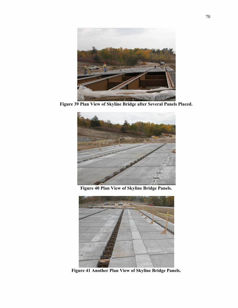
70
Figure 39 Plan View of Skyline Bridge after Several Panels Placed.
Figure 40 Plan View of Skyline Bridge Panels.
Figure 41 Another Plan View of Skyline Bridge Panels.

71
Figure 42 Plan View of a Typical Panel Channel.
Figure 43 Channel Details before the Post-tensioning Strands are Pulled Through.
Figure 44 Panel Shear Key Configuration.

72
Figure 45 Curing the Shear Key.
Figure 46 Plan View of Skyline Bridge before Post-tensioning.
Figure 47 Post-tensioning Channel with Strands Pulled through.
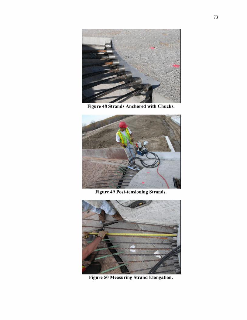
73
Figure 48 Strands Anchored with Chucks.
Figure 49 Post-tensioning Strands.
Figure 50 Measuring Strand Elongation.

74
Figure 51 Pouring Post-tensioning Channel.
Figure 52 Curing Post-tensioning Channels.
Figure 53 Curing Type K Cement Overlay.

75
Figure 54 Joint between Approach Slab and Floor End.
Figure 55 Galvanized Female Insert.
Figure 56 Barrier Reinforcement.

Figure
Figure
Figure 57 Completed Barrier.
Figure 58 Plan View of Completed Skyline Bridge.
Figure 59 Elevation of Completed Skyline Bridge.
76

77
2.1.6 System Overview
A number of innovations were introduced in the first generation of NUDECK system,
such as:
• Panels are made of high performance concrete that is precompressed in two directions
such that the residual stresses in service are compression and cracking is avoided.
• Most of the creep, shrinkage, and temperature change due to hydration take place
before the panel is connected with the rigid underlying beams, eliminating most of
cracking.
• The continuous gap over beam lines assures simple, high quality post-tensioning and
eliminates the question about the quality of tendon grouting.
• Individual post-tensioning of strands allows most contractors, even in areas not
familiar with post-tensioning, to do the post-tensioning work with local crews. The
precasters also would have the option to include post-tensioning as part of supplying
the panels.
• The proposed prestressed deck panel system covers the entire width of a bridge,
which eliminates the necessity of forming for the overhangs.
• All materials used in the production of the deck panels are non-proprietary and
readily available. This makes the system cost competitive with cast-in-place concrete
decks, while it is much more rapid to build and durable to maintain.
• Use of large diameter studs reduces the required number of studs. Thus, economy of
fabricated steel beams is improved and, more importantly, worker safety is enhanced.
• Finally, the cast-in-place overlay allows for adjustments in roadway profile. It
provides an excellent riding surface, and large cover for the reinforcement.

78
A number of lessons were learned from the construction of the Skyline Bridge, such as:
• Do not use Self Consolidating Concrete (SCC) if panels are crowned.
• Crowning is simpler when panel is not transversely pretensioned.
• Contractors prefer to prefabricate the panels if panels are not pretensioned.
• Wet transverse joint is good for tolerances, but slow to construct.
• Epoxy joints (such in segmental bridges) are fast to construct, but difficult for
tolerances.
• Simplify end of floor details.
• According to the contractor’s supervisor for the Skyline Bridge, one of the most time
consuming tasks was threading the post-tensioning strands through the open
longitudinal channels and curing the concrete overlay.
3.0 SECOND GENERATION NUDECK
The Skyline Bridge using the NUDECK system was completed successfully;
however, improvements could make the system more efficient. The areas of focus that
were emphasized while designing the second generation full-depth precast bridge deck
panel system include reducing cost and time of construction.
One major targeted improvement is to eliminate the concrete overlay, which
normally requires seven-day curing – a major disadvantage to rapid construction – and is
expensive. The most attractive option would not involve any additional overlay; rather,
the panels would be cast with ¼ - ½ inch additional thickness and ground to the required
elevation to provide a smooth riding surface. This system would significantly reduce the
number of construction steps. If an overlay is necessary, other options would include (1)

79
a waterproof membrane to protect the reinforcement from corrosion overlaid by a two
inch thick asphalt riding surface or (2) a thin epoxy concrete overlay. These systems
would reduce construction time, are easy to repair and replace, and cost less than a
concrete overlay.
Along the same lines, a rapid setting grout could be used to fill the transverse shear
key. This would enable the contractor to post-tension the deck soon after the panel-to-
panel connection is made. In addition, the approach slab and floor end panel support
could be poured with the same mix to reduce another construction step.
Another important objective of the second generation NUDECK was to develop and
implement a precast barrier. A precast barrier would reduce construction time as there
would be no need for forming, pouring, or curing a CIP concrete barrier. A precast
barrier would be easily replaceable; if one part of the barrier is damaged, the section is
removed and a new one is installed in its place.
Several changes to the details in the panel were made to increase the ease of
production, handling, and construction and to reduce cost. The length of the panels has
increased from eight feet to 12 feet. The increased panel size reduces the total number of
panels used on a given project by one-third. The No. 5 bars spaced at 12 inches for
secondary reinforcement and crack control are replaced by welded wire reinforcement,
which is easier to work with and eliminates tying of bars. The pretensioning strand
configuration has changed to four strands spaced at four feet from two strands spaced at
two feet. Furthermore, the crown location is moved to the open channel at a girder line,
when possible. Prior to shipping the panels for the Skyline Bridge project, three pockets
in the top of the panel (at the location of the crown) were not grouted, which resulted in

80
some cracking and larger deformations than expected. Moving the crown location to the
open channel at the girder line would eliminate damage that could be caused during
shipping and handling.
3.1 SECOND GENERATION NUDECK PROPOSED APPLICATIONS
The Nebraska Department of Roads (NDOR) originally chose the Interstate 80 over
Platte River Bridge to be built using the Second Generation NUDECK System.
Unfortunately, while in the system’s final stages of design, NDOR management decided
to allow the NUDECK system to be let as an alternate to CIP construction. The bridge
division decided to pull the precast deck panel system from the project and use it on
another bridge instead. The second application of the NUDECK system is on the 176th
Street over Interstate 80 Bridge. Details for optimizing the NUDECK system to fit both
of these projects are outlined in the following sections. Also, a project involving the use
of second generation precast panels for bridge re-decking will be presented.
3.1.1 I-80 over Platte River Bridge
NDOR is widening Interstate 80 between Lincoln and Omaha, Nebraska from two
lanes to three lanes in each direction to handle the large amount of traffic. Therefore, the
existing bridges over the Platte River were no longer adequate and new bridges were
needed. The new structures consist of twin, ten span bridges (one for each direction of
traffic) with end spans of 156 feet and interior spans of 166.5 feet for a total structure
length of 1644 feet. There is no skew on this bridge.
The deck system consists of full-depth precast deck panels that are 12 feet long with
a width equal to that of the bridge – 62 feet-8 inches. Six NU 2000 concrete girders
support the bridge deck. The precast panels are seven inches thick with a two inch

81
concrete overlay. A goal of the Second Generation NUDECK was to eliminate a
concrete overlay. However, the deck panels have open channels at the girder line
locations to facilitate post-tensioning. These channels are later grouted and the concrete
in this area will have a different color than the rest of the panel and drivers may be
confused between the grout and the lane lines. Therefore, an overlay is necessary on this
system; and since NDOR has a policy that only allows a concrete surface on its interstate
system in Eastern Nebraska, the possibility of an asphalt overlay is eliminated.
A simplified view of the deck panel can be seen in Figure 60. This application of the
NUDECK system implements a precast safety barrier. The precast bridge deck panels
are pretensioned transversely and post-tensioned longitudinally. Longitudinal post-
tensioning is located entirely in the open channels over the girder lines.
Figure 60 I-80 over Platte River Bridge deck panel.
3.1.1.1 Deck Panel Design and Details
This section discusses the design procedure and the standard details used for the
NUDECK Second Generation full-depth precast deck panel. The NUDECK panel was
designed based on AASHTO LRFD Bridge Design Specifications (2004). The following
assumptions were made during the development of the system:
Plan View
Elevation View
11'-0"3'-10"
2'-0"
4'-0"
4'-0"
2'-0"

82
1. Concrete strength at release, f’ci = 4500 psi, and concrete strength at 28 days, f’c =
8000 psi.
2. Prestressing strand is low relaxation, Grade 270 ksi – 0.5 inch diameter strands
for pretensioning and 0.6 inch diameter strands for post-tensioning. Conventional
reinforcement is Grade 60 ksi. Welded wire reinforcement (WWR) is Grade 75
ksi.
3. A two inch future wearing surface is included in the analysis.
4. The weight of the barrier is assumed to be 0.4 kips per foot.
Transverse prestressing strands are situated in three groups at four foot spacing.
Each group has four strands (two on top and two on bottom). At the end section of the
panel, five inch diameter spirals with one inch pitch surround each pair (top and bottom)
of strands. The spirals confine the concrete around the strands, thus, decreasing the
development length. This is necessary because the girder lines are left open for post-
tensioning and there is only three feet of concrete in the end section of the deck. In
addition, conventional reinforcement bars are used to transfer the compression force
across the open channel at the girder lines. Four bars surround each group of four
strands; as a result, the compression in the bars is equal to the tension in the strands. The
bar size is determined by its ability to resist buckling during prestress release and bending
during handling and erection. No. 10 bars provide the capacity to withstand this stress.
3.1.1.1.1 Positive and Negative Moment Regions
The I-80 over Platte River Bridge is designed using the approximate method (i.e.,
strip method). This method of analysis divides the deck into strips perpendicular to the
supporting girders and designs each strip as a continuous beam. For this method, the

83
extreme positive and negative moments apply to all sections of the deck panel. The
critical section for positive and negative moment is shown in Figure 61.
The panels are transversely pretensioned with twelve – 0.5 inch strands (six on top
and six on bottom). Additional panel reinforcement consists of WWR W4 x W4 at four
inch spacing with one layer on top and one on bottom just inside the cover requirements.
The longitudinal W4 reinforcement is needed for crack control prior to post-tensioning.
A detailed sketch of a typical panel’s reinforcement is shown in Figure 62.
Figure 61 Location of critical sections.
Figure 62 Reinforcement in typical panel section.
Section 2
Section A
4 - No. 10 Bar4 - 0.5 in. strand
2" 2"4 x 4 - W4 x W4 WWR
A
A
Plan View
Section A - A
1"
Girder Line
4 x 4 - W4 x W4 WWR
No. 10 Bar
0.5 in. strand
1'-6" 1'-6"9'-6" Deck
8"8"
8"8"
8"8"
2'-0"
4'-0"
4'-0"
2'-0"
7"

84
Based on all dead loads and HL-93 vehicular live load, the maximum factored
positive and negative moments (Mu) are 13.1 ft-kips/ft and 9.4 ft-kips/ft, respectively.
The deck panel’s flexural capacity (ΦMn) – determined using strain compatibility – is
equal to 14.8 ft-kips/ft. Service III Limit State is used for checking tension in prestressed
concrete structures with the objective of crack control. The NUDECK panel satisfied all
of the stress requirements.
3.1.1.1.2 Construction Loading
The two most common methods of installing precast deck panels involve either
placing the panels with a crane or using front-end loaders. The CAT 950F (Tadros &
Sun, 2004) is a typical front-end loader. Installing the precast panels requires such
loaders. The total weight of each machine is 35,000 lbs and its width is nine feet. About
70 to 80 percent of the machine’s weight goes to its front axle during panel erection. The
moment due to this machine is larger than HL-93 loading and will often control design.
An analysis was performed to determine the required positive reinforcement to resist
construction loading. The precast panel designed in the previous sections is also checked
for construction loads.
The total load due to two loaders is 70 kips. It is conservatively assumed that 80
percent of the load goes to the front axles when they carry a panel. Each deck panel is
installed by two loaders; therefore, the panel weight is distributed to four front wheels.
The panels are designed as a simple span beam supported by the girders. The total
factored moment (Mu), as calculated in section A.1.2, is 17.0 ft-kips/ft. The flexural
capacity (ΦMn) of a panel from the Platte River Bridge application is 14.0 ft-kips/ft,
which does not satisfy the strength requirement.

85
For this project, either the construction loads must be reduced by using cranes that
rest on the ground or the panels must be designed to handle the loads from front-end
loaders. If the latter approach is chosen, the W4 x W4 WWR should be replaced by W8
x W8 WWR, which gives a flexural capacity (ΦMn) equal to 18.6 ft-kips/ft. However,
W4 x W4 welded wire reinforcement is appealing because of its availability. It is
important to note that the arrangement of the loaders is very conservative. The maximum
moment is achieved by placing both loaders next to each other. This is unrealistic, as the
loaders would likely be spread apart to equalize the loading stresses exerted on the panel.
In addition, it is conservative to determine the moment demand based on a simply
supported beam model since the deck panel is connected at the girder lines by No. 10
bars and prestressing strands.
3.1.1.1.3 Overhang Design
The overhang of the full-depth deck panel is designed for a transverse vehicular
collision load and for dead and live loads. Since the LRFD states that the deck should be
stronger than the railing system used, the collision moment is determined based on the
reinforcement and geometry of the precast safety barrier.
The critical section of the overhang is 12 inches outside the centerline of the exterior
girder line. At this location, it is assumed that both the prestressing strands and the
threaded rods are fully developed. Spirals confine the concrete around the prestressing
strands, which allow the strands to be fully developed by the exterior girder line. The
high strength threaded rods have a shorter development length compared to conventional
bars and have a nut attached to the end to provide anchorage. The Grade 60 No. 10 bars
are developed at the critical section.

86
For a transverse vehicular collision, the moment due to the Extreme Event II Limit
State is equal to 36.8 ft-kips/ft. The flexural capacity (ΦMn) of the section is equal to
38.3 ft-kips/ft.
In the case of live load, the transverse strips are designed for the wheels of a 32.0 kip
axle. The center of the outside 16.0 kip wheel is positioned one foot from the barrier
interior face for the design of the deck panel overhang. The live load is multiplied by a
multiple presence factor and dynamic load allowance. According to the LRFD
Specifications (2004), the live load effects on an overhang are distributed over the
distance L = 45.0 + 10.0 X. This method is conservative as the structurally continuous
precast barrier distributes the live load over a larger distance. The total moment
(MSTRENGTH I) at the critical section due to dead and live loads is equal to 7.0 ft-kips/ft,
which is less than the capacity.
The overhang reinforcement extends to the second girder line of the precast panel.
No. 4 hairpins at four inch spacing provide additional reinforcement in the end sections
of the panel to confine the concrete around the area where the vehicular crash load is
transferred from the post to the panel. The end sections of the precast panel do not have
two layers of WWR as the other sections do. The WWR would be difficult to place in
the end sections as they already have a large amount of reinforcement. Figure 63 shows
the overhang reinforcement. Midwest Roadside Safety in Lincoln, Nebraska checked the
overhang design along with the design.
As an alternative, the panel was designed using 120 ksi coil thread rods instead of
150 ksi threaded rods. In order to complete the design using 120 ksi coil rods, a strength
design spreadsheet was set up to determine the panels’ flexural strength. A stress-strain

87
curve was added to the spreadsheet and the material yield strength used was 81 ksi (based
on fabricator tensile test data). The “power formula” is used to predict the stress-strain
relationship for the coil rod, and the curve fitting constants are assumed to be equal to
those of the 150 ksi threaded rod. This design would replace the four 150 ksi threaded
rods with 120 ksi coil rods. Also, the four No. 10 bars that are closest to the center of the
panel, at the panel’s top layer of reinforcement, would be changed to 120 ksi coil rods.
Using 150 ksi threaded rods would be the most economical option and is recommended
by UNL researchers; they have 50 percent greater strength and a comparable cost.

88
Figure 63 Reinforcement in panel ends.
3.1.1.1.4 Crowning the Panel
On this three-lane bridge, an off centered crown was located between the second and
third lanes. Creating a two percent crown on a transversely pretensioned precast panel is
a challenging assignment. Since the crown location is at a girder line, a simpler detail is
implemented compared to that on the Skyline Bridge. The precast panel is able to
#6 bar
#4 hairpin
sleeve from post
3'-10" 11'
A
A
#10 bars
4-0.5" strands
#4 hairpin x 18"5" O.D., 4.5" I.D. spiral1.25" TR w/ nut
1.25" TR w/ nutPL 1" x 8" x 14"
7"
8" 1' 1'8"8"1'1' 8"
6'
#10 (top & bot)
#10 (top & bot)
Option 2:
120 ksi CR (top)
Option 1:
#10 (bot)
#10 (bot)
Option 1:
120 ksi CR (top)
Option 2:
#10 (top & bot)
#10 (top & bot)
Option 1:150 ksi TR (top)
Option 2:120 ksi CR (top)
Option 1:150 ksi TR (top)
Option 2:120 ksi CR (top)
1" pitch spiral
6'
B
150 ksi nut
sleve from post
#4 hairpin x 18"
150 ksi nut
1.25" TR
PL 1" x 8" x 14"
Plan View
Section A - A
Section B
burn strandsback 2 in

89
maintain a constant deck thickness as the crowing detail allows the panel to rotate at the
open channel. The detail designed for the Platte River Bridge is shown in Figure 64.
Figure 64 Crown detail in open channel at girder line.
At the location of the crown, the bottom No. 10 bars across the open channel are cut
prior to placement of the concrete. After prestress release, the panel is set on a crowning
form and self-weight allows the panel to rotate to a two percent slope. Then, the bottom
No. 10 bars are welded together. The bars must be preheated to 200˚F since they are not
made of a weldable bar. It is also possible to ship the panels to the construction site flat
and form the crown onsite.
Because the bottom No. 10 bars are no longer continuous at the crown line, the top
No. 10 bars must withstand the entire load due to prestressing. Some of the force will
dissipate as the bottom strands try to close the gap; however, the compression in top bars
is large enough for buckling to occur. Buckling only becomes a problem if the top bars
shift upward causing concrete to spall off. As a result, a detail was added to prevent
upward buckling. A filler material is welded between the top and bottom bars, in the
location that is cast with concrete (Figure 65).
A 2.5" x 2.5" x 3/8" x 12"SAW CUT 1/4" GAP INTO LOWER #10
WELDED AS SHOWN ABOVE
4 3/4
PREHEAT BARTO 200
A 2.5" x 2.5"
#10

90
Figure 65 Crowning detail to prevent buckling.
3.1.1.1.5 Post-Tensioning Anchorage
The Platte River Bridge deck is designed with post-tensioning so there is zero tensile
stress in the negative moment region of the deck system under all dead and live loads.
This is a conservative approach; and though it increases creep in the panels due to the
high compressive forces in the positive moment sections, it will ensure a crack free
bridge deck. To achieve this level of prestress, 16 – 0.6 inch strands per girder line are
tensioned to 70 percent of their ultimate strength. The anchorage zone for this relatively
thin precast panel is critical when applying this large force.
3.1.1.1.6 Miscellaneous System Details
The Platte River Bridge’s geometry causes a reduction in the length of the bridge
deck end panels to seven feet (in the direction of traffic). The centerline of the precast
post is at 2 feet-6 inches from the edge of the end panel (end of floor). For these end
panels, only two sets of transverse prestressing strands are needed.
In this application, the precast panels are supported on the precast girders by
structural steel angles (Figure 66). The steel angles are welded to steel ties that are cast
into the girder and become flush with the girder’s top flange. The steel angles are used
for elevation adjustment and forming the haunch. UNL researchers recommended that
the haunch, post-tensioning channel, and overlay use the same concrete mix design. This
mix design is listed below in Table 4.
FILLER MATERIALWELDED BTW #10 BARS
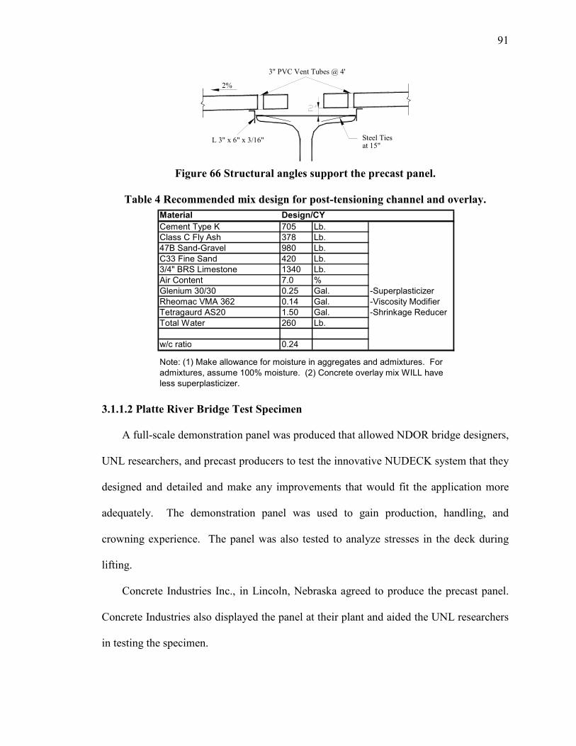
91
Figure 66 Structural angles support the precast panel.
Table 4 Recommended mix design for post-tensioning channel and overlay.
3.1.1.2 Platte River Bridge Test Specimen
A full-scale demonstration panel was produced that allowed NDOR bridge designers,
UNL researchers, and precast producers to test the innovative NUDECK system that they
designed and detailed and make any improvements that would fit the application more
adequately. The demonstration panel was used to gain production, handling, and
crowning experience. The panel was also tested to analyze stresses in the deck during
lifting.
Concrete Industries Inc., in Lincoln, Nebraska agreed to produce the precast panel.
Concrete Industries also displayed the panel at their plant and aided the UNL researchers
in testing the specimen.
L 3" x 6" x 3/16"
3" PVC Vent Tubes @ 4'
2%
Steel Tiesat 15"
Material Design/CY
Cement Type K 705 Lb.
Class C Fly Ash 378 Lb.
47B Sand-Gravel 980 Lb.
C33 Fine Sand 420 Lb.
3/4" BRS Limestone 1340 Lb.
Air Content 7.0 %
Glenium 30/30 0.25 Gal. -Superplasticizer
Rheomac VMA 362 0.14 Gal. -Viscosity Modifier
Tetragaurd AS20 1.50 Gal. -Shrinkage Reducer
Total Water 260 Lb.
w/c ratio 0.24
Note: (1) Make allowance for moisture in aggregates and admixtures. For
admixtures, assume 100% moisture. (2) Concrete overlay mix WILL have
less superplasticizer.

92
Figure 67 through Figure 75 show the panels before and after casting. The panel’s
reinforcement is detailed as it is described previously in 2.2.1.1 Deck Panel Design and
Details. Concrete Industries choose to use the design option with 120 ksi coil thread rods
because of material availability. Half of the demonstration panel has open channels at the
girder lines as described for the Platte River Bridge application. The other half of the
panel does not have open channels; rather, there are blockouts to the mid-depth of the
panel creating ducts that run the length of the panel with vent tubes at four foot spacing.
This demonstrates a panel design that would avoid an overlay – a major goal of the
Second Generation NUDECK. The demonstration panel also features post-tensioning
anchorage plates and represents a 12 foot long end panel.
Figure 67 Demonstration panel reinforcement setup and formwork.

93
Figure 68 End of panel reinforcement.
Figure 69 Precast post is cast into the panel.
Figure 70 Exterior face of post with strands protruding.

94
Figure 71 Girder line with mid-depth duct and vent tubes.
Figure 72 Post cast with deck panel.
Figure 73 No. 10 bars cut at crown location.

95
Figure 74 Anchorage plate cast into the deck panel.
Figure 75 Anchorage plate at the crown location.
3.1.1.2.1 Handling Analysis
This test on the demonstration panel analyzed the strains in the deck during handling.
During the Skyline Bridge project, the original NUDECK experienced some cracking
during shipping and handling. Panel lifting was investigated to verify that the theoretical
stresses and strains used to design the panels indeed matched the actual stresses and
strains. Eight strain gages were attached to the middle of eight – 15 inch long No. 4 bars.
Four of these bars were placed in the positive moment section of the panel and four of

96
these bars were placed in the negative moment section. The bars were tied to the W4 x
W4 WWR and concrete was cast in the panel. Each strain gage was located 1.5 inches
from the extreme fiber of the panel. Figure 76 shows the setup of the strain gages in the
panel and the location of the lifting inserts. Figure 77 shows a strain gage attached near a
lifting insert.
Figure 76 Strain gage setup for lifting analysis.
Figure 77 Strain gage in negative moment section.
Following prestress release, the panel was lifted from the bed using an overhead
crane. The panel was then set back down and lifted again to allow the computer to gather
two lift readings from the strain gages. Figure 78 shows the panel as it is lifted from the
bed. The results recorded by the computer were plotted on a chart, which is shown in
Figure 79. This chart shows the strain plotted against time for the two strain gages
6'-6" 17'-4" 15'-0" 17'-4" 6'-6"LIFTING
6'-0"
3'
3'
LIFTING POINTS
STRAIN GAGE
NO. 4 BAR
POS. MOMENT NEG. MOMENT
POINTS
Strain gage
Lifting insert
No. 4 Bar
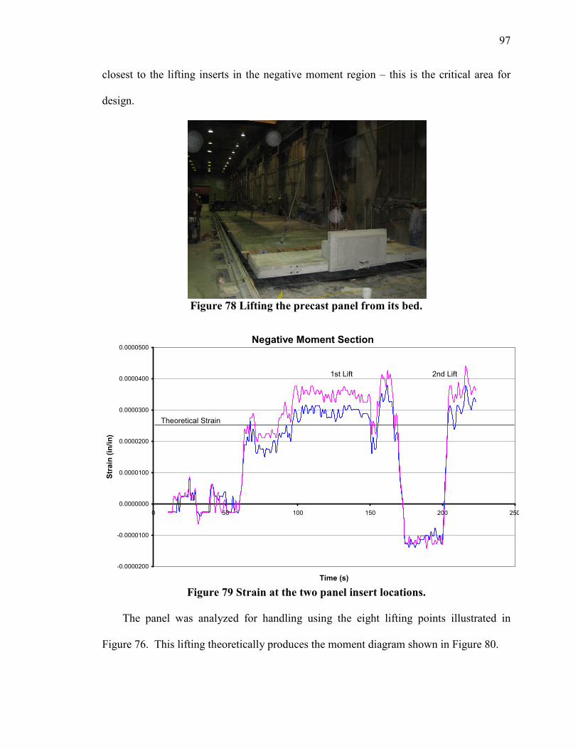
97
closest to the lifting inserts in the negative moment region – this is the critical area for
design.
Figure 78 Lifting the precast panel from its bed.
Figure 79 Strain at the two panel insert locations.
The panel was analyzed for handling using the eight lifting points illustrated in
Figure 76. This lifting theoretically produces the moment diagram shown in Figure 80.
Negative Moment Section
-0.0000200
-0.0000100
0.0000000
0.0000100
0.0000200
0.0000300
0.0000400
0.0000500
0 50 100 150 200 250
Time (s)
Strain (in/in)
1st Lift 2nd Lift
Theoretical Strain

98
Figure 80 Theoretical moment due to lifting the panel (in-kips).
Using this moment diagram, researchers calculated the theoretical strain in the strain
gage and compared it to the actual strain recorded by the computer. The procedure was
completed as follows:
Mat insert = 137.6 in-kips
Ec = 4200 ksi; Es = 29000 ksi
n = =4200
29000 6.9
Itr = Ig + (Isteel)(n-1)
= ( ) ...712
72 3 +
…+ ( ) ( )( )( ) ( )( )( ) ( )( )( )[ ]( )19.6024.2153.03639.127.13161.204.0182 222 −++
= 2241 in4
( )( )2441
774.16.137==
tr
cI
Myf = 0.1089 ksi
sf = n*fc = (6.9)(0.1089) = 0.7519 ksi
e = 290007519.0
=E
f s = 0.00002592 in/in
The actual strain is about 30 percent greater than the theoretical strain calculated in
the panel (shown in Figure 79). This difference is likely due to the assumptions used in
the analysis. The panel was analyzed as if it is supported by a continuous support that ran
the entire length of the panel (12 feet) opposed to two lifting points. These two lifting
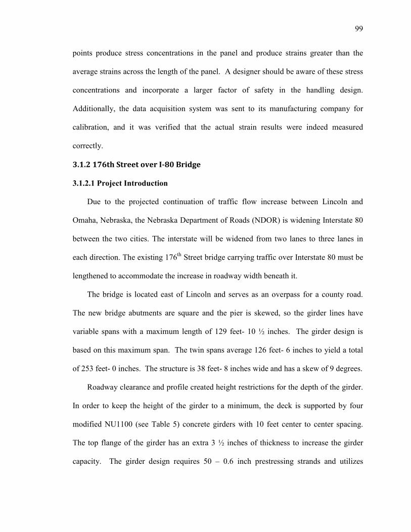
99
points produce stress concentrations in the panel and produce strains greater than the
average strains across the length of the panel. A designer should be aware of these stress
concentrations and incorporate a larger factor of safety in the handling design.
Additionally, the data acquisition system was sent to its manufacturing company for
calibration, and it was verified that the actual strain results were indeed measured
correctly.
3.1.2 176th Street over I-80 Bridge
3.1.2.1 Project Introduction
Due to the projected continuation of traffic flow increase between Lincoln and
Omaha, Nebraska, the Nebraska Department of Roads (NDOR) is widening Interstate 80
between the two cities. The interstate will be widened from two lanes to three lanes in
each direction. The existing 176th Street bridge carrying traffic over Interstate 80 must be
lengthened to accommodate the increase in roadway width beneath it.
The bridge is located east of Lincoln and serves as an overpass for a county road.
The new bridge abutments are square and the pier is skewed, so the girder lines have
variable spans with a maximum length of 129 feet- 10 ½ inches. The girder design is
based on this maximum span. The twin spans average 126 feet- 6 inches to yield a total
of 253 feet- 0 inches. The structure is 38 feet- 8 inches wide and has a skew of 9 degrees.
Roadway clearance and profile created height restrictions for the depth of the girder.
In order to keep the height of the girder to a minimum, the deck is supported by four
modified NU1100 (see Table 5) concrete girders with 10 feet center to center spacing.
The top flange of the girder has an extra 3 ½ inches of thickness to increase the girder
capacity. The girder design requires 50 – 0.6 inch prestressing strands and utilizes

100
innovative negative moment continuity for deck self weight and superimposed dead
loads. Prior to the placement of the deck, 50 feet long 150 ksi high strength threaded
rods are centered on top of the girders above the pier in the negative moment region.
Concrete is cast around the threaded rods to create mechanical interlocking for the
transfer of shear and negative moment forces between the girders. The ends of the girders
in this section are blocked out 3 ½ inches and have unique c-shape reinforcement to allow
the placement of the threaded rods and confine the concrete.
Table 5 Modified NU1100 Properties.
The bridge deck system utilizes the NUDECK Second Generation full depth precast
panels. These panels are 8 feet in length, 7 inches in depth, and are the full width of the
bridge deck– 38 feet- 8 inches. The panels will have an asphalt overlay 2 inches thick to
protect the deck panels from water and salts as well as to provide a smooth and uniform
driving surface. The precast panels have a modular design which can be adapted for
other bridges and are not skewed. The deck panels have an open channel at the girder
lines for post-tensioning and strands are threaded through the transverse rebar and located
at the center of the panel.
The post-tensioning anchorage occurs in precast approach slabs. The approach slabs
span longitudinally and transverse continuity is created with an innovative joint detail.
The approach slab transverse reinforcement extends past the side and returns into the
Section
Properties NU1100+3.5"
h (in) 46.8
A (in.2) 863.65
yb (in.) 24.58
I (in.4) 270,513
Wg (k/ft) 0.900

101
panel in a c-shape. For mechanical interlock, longitudinal bars are placed in the corners
of the overlapped transverse c-bars after the panels are placed next to one another.
The precast bridge deck panels are pretensioned transversely and have a rebar grid
12 inches by 12 inches for crack control. Composite action is achieved through 1 3/8”
high strength threaded rod spaced at 24 inch intervals in the girder and is placed in the
open channel between reinforcement. The open channel in both the deck panels and the
approach slab panels are grouted after post-tensioning.
3.1.2.2 Panel Elevation
Structural steel angles are used to set the elevation of the panel and to create a grout
dam. Prior to panel placement on the concrete girders, steel angles L6x2 (with the long
leg upward) are set to the proper elevation and are welded to transverse steel angles
L1.5x1.5 spanning the top of the girders. The L1.5x1.5 angles are spaced at 24 inches on
center along the length of the girder. The L6x2 height can be adjusted with the varying
haunch to form the camber profile. For a mid-span section, Figure 81 shows these angles
attached to the girders before panel placement. The section at the pier is shown in Figure
82. An added benefit of this leveling system is that it also provides the majority of the
formwork for the haunch.
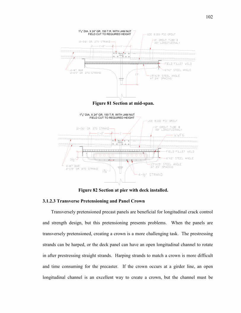
102
Figure 81 Section at mid-span.
Figure 82 Section at pier with deck installed.
3.1.2.3 Transverse Pretensioning and Panel Crown
Transversely pretensioned precast panels are beneficial for longitudinal crack control
and strength design, but this pretensioning presents problems. When the panels are
transversely pretensioned, creating a crown is a more challenging task. The prestressing
strands can be harped, or the deck panel can have an open longitudinal channel to rotate
in after prestressing straight strands. Harping strands to match a crown is more difficult
and time consuming for the precaster. If the crown occurs at a girder line, an open
longitudinal channel is an excellent way to create a crown, but the channel must be
138" DIA. X 24" GR. 150 T.R. WITH JAM NUTFIELD CUT TO REQUIRED HEIGHT
138" DIA. X 24" GR. 150 T.R. WITH JAM NUTFIELD CUT TO REQUIRED HEIGHT
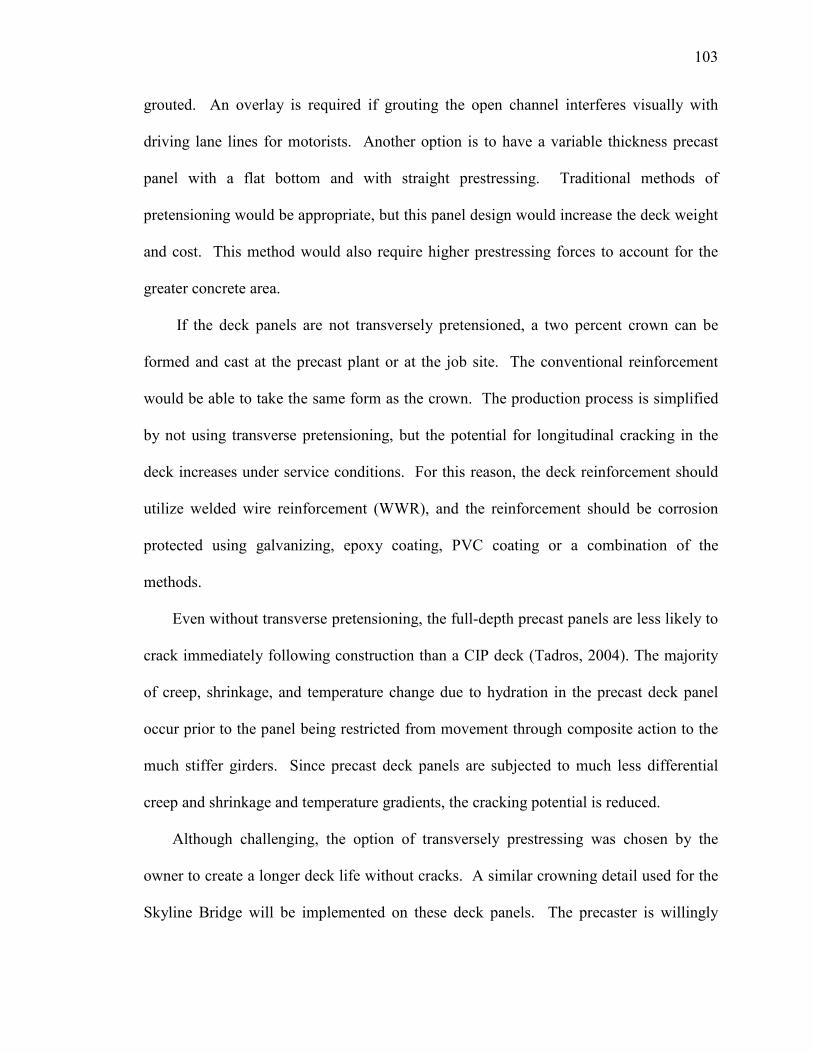
103
grouted. An overlay is required if grouting the open channel interferes visually with
driving lane lines for motorists. Another option is to have a variable thickness precast
panel with a flat bottom and with straight prestressing. Traditional methods of
pretensioning would be appropriate, but this panel design would increase the deck weight
and cost. This method would also require higher prestressing forces to account for the
greater concrete area.
If the deck panels are not transversely pretensioned, a two percent crown can be
formed and cast at the precast plant or at the job site. The conventional reinforcement
would be able to take the same form as the crown. The production process is simplified
by not using transverse pretensioning, but the potential for longitudinal cracking in the
deck increases under service conditions. For this reason, the deck reinforcement should
utilize welded wire reinforcement (WWR), and the reinforcement should be corrosion
protected using galvanizing, epoxy coating, PVC coating or a combination of the
methods.
Even without transverse pretensioning, the full-depth precast panels are less likely to
crack immediately following construction than a CIP deck (Tadros, 2004). The majority
of creep, shrinkage, and temperature change due to hydration in the precast deck panel
occur prior to the panel being restricted from movement through composite action to the
much stiffer girders. Since precast deck panels are subjected to much less differential
creep and shrinkage and temperature gradients, the cracking potential is reduced.
Although challenging, the option of transversely prestressing was chosen by the
owner to create a longer deck life without cracks. A similar crowning detail used for the
Skyline Bridge will be implemented on these deck panels. The precaster is willingly

104
working with NDOR and UNL engineers to develop the best crown detail possible. A
typical bridge cross-section with the crown formed in the panel at a constant deck
thickness is shown in Figure 83. The precast panel is able to maintain a constant deck
thickness as the crowing detail allows the panel to rotate at the joint detail.
Figure 83 Typical mid-span cross-section of the 176th over I-80 Bridge.
3.1.2.4 Positive and Negative Moment Sections
The 176th Street over I-80 Bridge NUDECK precast deck system is designed using
the Approximate Method (Strip Method). The deck is divided into unit strips that are
perpendicular to the supporting girders, and each strip is designed as a continuous beam.
The girders are considered rigid supports with zero settlement and their width is taken
equal to zero. The extreme positive and negative moments are applicable to all sections
of the deck panel. The critical sections for positive and negative moment are shown in
Figure 84.
Figure 84 Locations of critical sections.
For the main transverse reinforcement, the panels are transversely pretensioned in
two layers with eight – 0.5 inch strands (four on top and four on bottom). Pairs of strands
are placed at two feet centers and located as close to the outside surfaces as permitted by
4'-4"10'-0" 10'-0"10'-0"
7"7"
4'-4"
NU 1100
Modified
50-0.6" STRANDS
2" ASPHALT OVERLAY
7" STRUCTURAL DEPTH
Section 2
Section A

105
cover requirements. For the NUDECK, the bottom clear cover requirement is 1.0 inch,
and the top clear cover requirement is 2.0 inches below the design depth. The distance
between the centroids of the strands is 3 ½”. Additional panel reinforcement consists of
two layers of #3 rebar at 12” each way. The longitudinal bars in both layers are placed to
the inside face of the transverse reinforcement. The transverse bars are tied to the
longitudinal bars and spaced longitudinally in-between the ½” prestress strands leaving
6” on either side of the strands. The additional reinforcement is needed for crack control
prior to post-tensioning, during lifting, transporting, and erection. A detailed plan view
of a typical c is show in Figure 85. Elevation views of the panel at girder line and mid-
span are shown in Figure 86 and Figure 87.
The purpose of longitudinal reinforcement in the bridge deck is to distribute the live
load and control cracking. The longitudinal reinforcement provided by the #3 rebar grid
helps control transverse cracking because a greater number of smaller diameter
reinforcement bars spaced closely together limits the maximum crack width (Nawy,
2005). Welded wire reinforcement could be used but was not detailed for this bridge
project.
Figure 85 Plan view of the panel reinforcement.
SOLID SHEAR KEY
4'-4" 10'-0" 10'-0" 10'-0" 4'-4"
1'-0"
2'-0"
2'-0"
2'-0"
1'-0"
8'-0"
FULL DEPTH
CHANNEL2-0.5" PRESTRESS
STRANDS @ 2'-0"
4"
2"
38'-8"
TOP &
BOTTOM:
8 #3 BAR
12" CTRS.
9'-0"3'-10"
TOP #8 BAR 6'-8" LONG
BOT. #7 BAR 6'-8" LONG 2'-0"1'-0"2'-0"
#3 @ 12" CTRS.
TOP & BOTTOM6"6" 1 1/2"
4 #7 BAR
5' LENGTH
3'-10"
7'-0"
6"
2"
2"
1'-0"
3'-3"2"
#5 DPS591 TOP AT 12" CTRS.
#5 DPS592 BOTTOM

106
The ½ inch transverse prestressing strands are continuous for the width of the deck
panel. Since the post-tensioning occurs in a longitudinal continuous open channel, the
prestress force must be transferred across the channel. This is accomplished by
surrounding the pairs of prestress strands with a total of 4 #7 bars in pairs 2 inches from
either side of the ½ inch strands. The bars are 5 feet in length, and the embedment
creates a fully developed bar on either side of the channel. Since the panel consists of
four separate sections, these #7 bars must also be able to resist the moments applied
during lifting and transportation.
Figure 86 Elevation view at the girder line section.
Figure 87 Elevation view at the mid-span section.
The transverse shear key detail is shown in Figure 88 and consists of matching v-
shape faces that create a diamond pattern when placed together. The bottom gap is
spaced at ½ inch, and foam backer rod is used to form the bottom of the grout dam. The
top gap is 3 ½ inches and is wide enough for easy grouting and installation. On each side
of the longitudinal joint, the transverse shear key is stopped and made flat for 6 inches.
The locations of the solid shear key are shown in the plan view of Figure 85. The panels
from Skyline Bridge experienced some breaks of the shear key next to the longitudinal

107
joint because the concrete layer is very thin and weak at the edge. This detail will help
eliminate potential breaks by increasing the thickness and strength.
Figure 88 Deck panels transverse joint details.
3.1.2.5 Post-Tensioning
The NUDECK utilizes an innovative post-tensioning system. Two different post-
tensioning systems were developed for the NUDECK. The chosen system utilizes an
open longitudinal channel at each girder line with the post tensioning strands threaded
through the transverse deck reinforcement as shown in Figure 81. With an open
longitudinal channel, panel installation is easier because there are no hidden shear
pockets to align with girder horizontal shear reinforcement. Also, high quality control
during grouting is achieved with the open longitudinal channel because of the access and
visibility to the entire length of the girder. However, some problems are associated with
the open longitudinal channel. The transverse prestress must be transferred to the
opposing sections, and the panel must be detailed to hold together as a single unit during
lifting, transport, and installation. To preserve the compression in the transverse
direction, the absent concrete in the channel is replaced with four No. 7 bars at the
location of each pair of strands (see Figure 85 and Figure 86). These bars also support
the panels during shipping and handling.

108
The full-depth precast panels are post-tensioned in the longitudinal direction to
reduce transverse joint separation, transverse cracking, and for negative moment
reinforcement at the pier. The post-tensioning adds compressive force in the panel and
across the transverse joint. Long term durability is enhanced by reducing transverse
cracking potential and increasing the water tightness of the joints. The post-tensioning is
applied after the transverse shear keys are grouted and attain adequate strength but before
composite action is created through grouting the longitudinal channels. Thus, the post-
tensioning force is completely applied to the deck rather than sharing the force with much
stiffer girders.
Through analysis under Service III conditions, 10 – 0.6 inch strands per girder line
prestressed to 70 percent of the ultimate strength at transfer are required. The post-
tensioning force yields a maximum tensile stress of 345 psi in the negative moment
region directly above the center pier when the deck system is under all dead and live
loads. The deck experiences compressive forces greater than 250 psi in all other regions
besides the center pier. The maximum tensile stress is about half the cracking limit of
0.19√f’c and can be reduced to zero by increasing the number of 0.6 inch post-tensioning
strands per girder line to 16.
3.1.2.6 Anchorage Zone Detail
The anchorage zone for the post-tensioning is a critical detail to accommodate rapid
construction and allow the system to effectively transfer the prestressing force to the deck
without any harmful effects. To avoid anchorage details in the end panel, reinforced
precast NU Approach slabs were designed. These slabs span 20 feet from the grade beam
to the abutment of the bridge and will be longitudinally post-tensioned with the deck

109
panels. The underlying soil is assumed to settle therefore requiring the slab to span the
distance. The slabs are 12 inches thick, and the main reinforcing steel runs
longitudinally. The elevation view of the approach slab is shown in Figure 89. The top
of the approach slab and deck panels are at the same elevation and will have the same 2
inch asphalt overlay. The approach slabs are spaced at 10 feet centers and have a width
of 9’-4”, leaving an eight inch joint in the longitudinal direction. The approach slab
panel end next to the deck panels has a transverse joint which matches the deck panel.
Even if cracking occurs at the transverse joint, the overlay will help protect the
reinforcement from corrosion by blocking water and chlorides from entering the concrete
cracks in the structural deck member.
Figure 89 Approach slab elevation view.
The anchorage is provided by a Dywidag Systems plate anchorage type 0.6” 6805
(Dywidag-Systems International, 2007). Each end panel has two anchors for 5-0.6”
strands spaced 2’ apart transversely, and the elevation details are given in Figure 90.
Confinement of the anchorages is achieved with 19 #4 hairpin rebars at 2 inch spacing
(about 3 feet total length), see Figure 91. The minimum duct diameter for five 0.6”
strands is 2 inches to allow for strand installation and effective grouting.
0.6" PT STRAND

110
Figure 90 Anchorage hardware.
Figure 91 #4 confinement hairpin details.
The confinement reinforcement steel required was determined to be 1.46 in2 by using
the Gergly Method (Nawy, 2006). By Tuan et al.’s recommendation, this would require
8 #4 confinement hairpins at 2 inches (Tuan, Yehia, Jongpitaksseel, & Tadros, 2004), but
the owner opted to add extra #4 hairpins at 2 inch spacing up to 38 inches. The #4
hairpins are inexpensive and provide an increase in the factor of safety. The end zone
was assumed to be distributed over 5 feet of the 12 inch slab. The load distribution and
anchorage plate size is diagramed in Figure 92.
5 0.6" PT STRANDS PER DUCT

111
Figure 92 Load distribution and anchorage plate minimum size.
The total load on each duct is ( )( ) kipPductkksiinstrandsP total 434/217200217.05 2 =⇒==
Distribution of the force = w = inkftkft
k/23.7
12
1*/8.86
5
434==
Assume ( ) "40"603
2
3
2=== hz
From RISA, the maximum moment is 97.7 k-ft or 1172 k-in as shown in the
following diagram.
Figure 93 End zone anchorage maximum moment.
kipsin
ink
z
MT 3.29
40
1172max =−
==
246.120
3.29in
ksi
kips
fTA
ss ===
The longitudinal reinforcing steel includes 10-0.6” draped post-tensioning strands,
#6 rebar in the bottom at 6 inch spacing, and #4 rebar in the top layer at 12 inch spacing.
In an elevation view, the post-tensioning tendons are anchored in the mid-height of the
panels, draped to a minimum cover to increase the flexural capacity, and then brought to
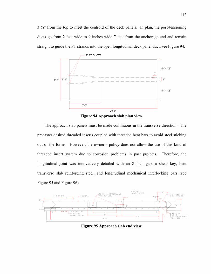
112
3 ½” from the top to meet the centroid of the deck panels. In plan, the post-tensioning
ducts go from 2 feet wide to 9 inches wide 7 feet from the anchorage end and remain
straight to guide the PT strands into the open longitudinal deck panel duct, see Figure 94.
Figure 94 Approach slab plan view.
The approach slab panels must be made continuous in the transverse direction. The
precaster desired threaded inserts coupled with threaded bent bars to avoid steel sticking
out of the forms. However, the owner’s policy does not allow the use of this kind of
threaded insert system due to corrosion problems in past projects. Therefore, the
longitudinal joint was innovatively detailed with an 8 inch gap, a shear key, bent
transverse slab reinforcing steel, and longitudinal mechanical interlocking bars (see
Figure 95 and Figure 96)
Figure 95 Approach slab end view.
2'-0"
7'-0"
9'-4"
20'-0"
4'-3 1/2"
9"
4'-3 1/2"
2"
2" PT DUCTS
APPROACH SLAB END VIEW PARALLEL REIN.

113
Figure 96 Approach slab longitudinal joint continuity detail.
The approach slab panels are placed next to one another with an 8 inch gap in-
between. The transverse top and bottom #4 rebars are bent 90 degrees at an 8 inch
extension past the lower lip of the shear key after curing the panels. The upper bars are
bent down, and the lower bars are bent upward. When the panels are placed next to one
another, the bent bars create a closed loop. Mechanical interlock is obtained with a steel
anchorage/splice by placing two #4 bars in the top corners and two #6 bars in the bottom
corners of the closed loop. The panels are field formed for grouting/cementing the
longitudinal joint at the same time as the deck panel longitudinal joints after post-
tensioning occurs. The joint will provide continuity in the transverse direction.
3.1.2.7 Alternate Post-Tensioning System
Alternate post-tensioning system details were developed to increase the speed of
construction. According to the contractor’s supervisor for the Skyline Bridge, one of the
most time consuming construction steps of the first generation NUDECK was threading
the post-tensioning strands through the open longitudinal channels and curing the
concrete overlay. In the alternate post-tensioning system, the strands are easily and
rapidly placed on top of the concrete girders prior to deck panel installation. Anchorage
box details facilitate easy and rapid post-tensioning.

114
The post-tensioning strands lie beneath the deck panels on top of each girder line
rather than inside a duct or threaded through the deck reinforcement in an open
longitudinal channel. This detail allows the contractor to easily and rapidly install the
post-tensioning strands. A major benefit of this detail is that an overlay is not required
because the precast panels do not have longitudinal channels at the girder lines for post-
tensioning. The only exposed grout visible to motorists is the small transverse joints
every 8 feet which will not be confused as lane lines. Lastly, this detail is better for
maintenance. The precast panel system is expected to last as long as the superstructure,
but if a localized damaging event occurs to the deck, individual deck panels could be
removed and replaced without cutting the post-tensioning.
3.1.2.8 Alternate Post-Tensioning Details
An alternate post-tensioning anchorage system was developed for the NUDECK
panels considering anchorage occurring in the two end panels and longitudinal strands
placed beneath the deck panels. In order to ensure the prestressing force is applied to the
centroid of the deck, the strands are brought up to the mid-height of the deck in the last
panel and inserted into a steel anchorage box at each girder line. The last four feet of
both end panels have continuous open channels at each girder line 4 ½ inches deep, 22 ½
inches wide, and 48 inches long. These channels allow the prestress strands to freely
angle from the bottom of the deck panel 4 inches to its mid-height. A ¾ inch thick steel
box with shear studs welded to its sides is embedded into the deck to transfer the post-
tensioning force to the deck. Figure 97 through Figure 99 are schematics of this detail.

115
Figure 97 Elevation view of the longitudinal post-tensioning strands under the
panel.
Figure 98 Side elevation view of the post-tensioning anchorage box.
Figure 99 Plan view of the post-tensioning anchorage box.

116
The prestressing strands are placed on the girders prior to panel installment, and a
minimum of 4 feet of extra strand is left at each end. Each end panel is installed without
the 48 inch long, one inch thick removable end plate. The end plate has 10 - one inch
diameter holes drilled 4 inches from the bottom and 2.25 inches on center (see Figure
100). The strands are easily threaded through a removable end plate beside the deck
panel and are raised vertically through the notched ¾ inch thick end plate. The
removable plate is then positioned to align the strands at 4 inches from the bottom of the
panel. In order to provide a perpendicular jacking surface, the chucks are aligned parallel
to the strands by fabricating the notched end plate at a 4.8 degree slope.
The post-tensioning force is resisted by shear studs and bearing on the concrete
through the steel box. Since high bearing stresses result in cracking, the post-tensioning
force is largely transferred to the deck through the shear studs. A total of 16 - ¾ inch
diameter shear studs (8 per side) are welded horizontally 2 ½ inches from the bottom of
the panel. The shear studs are slightly above the bottom deck reinforcement and have 6
inches spacing. Either welded wire reinforcement or number 4 rebar is used to control
the bursting cracks around the steel box. The bottom layer of reinforcement must be cut
at the open channels to enable the prestressing strands to freely angle to the mid-height of
the deck without threading the strands through reinforcement. The reinforcement tensile
capacity is transferred through the steel box by overlapping the shear studs and the
bottom deck reinforcement. This detail allows the contractor to easily and rapidly install
the post-tensioning strands.

117
Figure 100 End view of the plates for the post-tensioning anchorage box.
Since the panels are not connected to the girders prior to post-tensioning, the
moment created in the deck panels due to the eccentricity of the strands is a potential
problem. The deck panel post-tensioning was modeled with an iterative process in RISA-
3D using equivalent forces. The strands are assumed to be prestressed to 70 percent of
the ultimate strength at transfer. This equates to approximately 410 kips per girder line
when 10- 0.6 inch strands are used. Equivalent vertical forces are placed at the location
of the assumed draping point. A deck panel width of 10 feet is assumed to apply to one
girder line to evaluate a 1 kip per linear foot uniformly distributed self weight load. The
deck is assumed to be a continuous member because the transverse shear keys are grouted
and cured prior to the time of post-tensioning.
To begin with, vertical restraints were placed at 1 foot intervals along the entire span
of one girder line. The vertical reactions due to post-tensioning alone and due to self
weight alone were determined, and the difference between them was calculated. If any
reaction was a tensile force, the vertical reaction was removed, and the model was
reanalyzed. This iterative process was repeated until no tensile forces occurred. At this

118
point, the deflection of the deck was determined. Using an 8 feet draping point in the
model, the deck panel deflected upward a maximum of 0.13 inch directly above the
draping point.
Since the post-tensioning moment in the deck panels creates a small camber in the
model, an anchorage device is being devised to relieve the deck panel of the vertical force
and direct it into the girder. A preliminary detail is to create a roller out of a pipe placed
over a 1 1/8” rod, and bend the rod into a trapezoid (see Figure 101). The bent rod is
embedded eight inches into the girder. The draping point was reduced to 4 feet from 8
feet since the vertical force is removed from the deck panel and detailing becomes easier.
As shown in Figure 97, the vertical anchorage device is just less than 4 feet from the end
of the deck and is contained within the open channel in the deck. The vertical anchor has
a roller with a bottom elevation equivalent to the bottom of the deck. The prestressing
strands pass beneath the roller and are draped to the same elevation as the bottom of the
deck. After post-tensioning occurs, the open channel is grouted with the haunch, so the
strands will be protected against corrosion.
Figure 101 Cross section view of the vertical force anchor.

119
3.1.2.9 Composite Action – Horizontal Shear
Even though the NUDECK panels are not CIP, the deck is made fully composite
with the supporting girders. After post-tensioning occurs, the deck panels are made
composite with the girders through a simple and efficient detail. Horizontal shear
reinforcement in precast girders designed for CIP decks typically extends the vertical
shear reinforcement past the top flange of the girder and bends the reinforcement parallel
to the flange. This method is impractical for precast deck panels because the horizontal
shear reinforcement is not clustered to fit in-between the deck transverse reinforcement or
deck panel shear pockets.
As a general rule, the fewer number of shear pockets that a panel has results in cost
reduction for forming the panel. The panels are also easier to install because less
hardware has to be aligned. The NUDECK is detailed with a continuous longitudinal
channel and transverse reinforcement passing through the joint. Therefore, the horizontal
shear reinforcement must be detailed to fit in-between the transverse shear reinforcement.
The AASHTO Standard and LRFD Specifications do not provide requirements for the
maximum spacing of stud clusters. Based on recommendations given by the AASHTO
specifications for shear connectors used with CIP deck slabs, the common practice is to
limit the spacing to a maximum of 24 inches (PCI, 2006).
In order to minimize the number shear connectors required in the deck panels, high
strength threaded rod is used for the shear connectors. Grade 150 ksi 1-3/8 inch diameter
threaded rods (Williams Form Engineering Corp, 2007) are spaced at 24 inches on center
along the length of the girder line. This spacing is greater than the minimum of 6 inches

120
as based on the AASHTO specifications requiring the minimum stud spacing at 4 times
the stud diameter.
The threaded rods are cast with additional height above the top of the girder to
account for variable camber and are anchored with a washer and jam nut on the bottom.
Once the girder is in its final position and the camber and deflection have been
determined, the threaded rods are field cut to the required elevation of the deck panel. A
2 ¾ inch jam nut is then placed toward the top of the threaded rod at its final elevation to
provide interlocking and prevent uplift. The longitudinal channels are then grouted with
the haunch after the panels are post-tensioned.
The strand profile is needed to determine the centroid of the tensile reinforcement on
the tensile face. In order to help reduce the camber and release strength and increase the
shear capacity, 5 rows of 2 strands were harped at the 0.4L point. The total number of
0.6” strands is 50, and the number of draped strands is 10. The strand profile is given
below in Table 6.
Table 6 Strand profile and centroids of the strand.
0.0L 0.0231L 0.1L 0.2L 0.3L 0.4L 0.5L 0.6L 0.7L 0.8L 0.9L 1.0L
Layer Aps Initial Prest fpi Depth ys (in) Depth ys (in)
Depth ys
(in)
Depth ys
(in)
Depth ys
(in)
Depth ys
(in)
Depth ys
(in)
Depth ys
(in)
Depth ys
(in)
Depth ys
(in)
Depth ys
(in)
Depth ys
(in)
1 0.434 202.5 39.55 37.844 32.163 24.775 17.388 10.000 10.000 10.000 17.388 24.775 32.163 39.55
2 0.434 202.5 37.55 35.844 30.163 22.775 15.388 8.000 8.000 8.000 15.388 22.775 30.163 37.55
3 0.434 202.5 35.55 33.844 28.163 20.775 13.388 6.000 6.000 6.000 13.388 20.775 28.163 35.55
4 0.434 202.5 33.55 31.844 26.163 18.775 11.388 4.000 4.000 4.000 11.388 18.775 26.163 33.55
5 0.434 202.5 31.55 29.844 24.163 16.775 9.388 2.000 2.000 2.000 9.388 16.775 24.163 31.55
6 0.00 14
7 0.00 12
8 0.00 10
9 0.00 8
10 2.17 202.5 6 6 6 6 6 6 6 6 6 6 6 6
11 3.04 202.5 4 4 4 4 4 4 4 4 4 4 4 4
12 3.47 202.5 2 2 2 2 2 2 2 2 2 2 2 2
13 0.61 200 41.55 41.55 41.55 41.55 41.55 41.55 41.55 41.55 41.55 41.55 41.55 41.55
10.850 10.850 10.850 10.850 10.850 10.850 10.850 10.850 10.850 10.850 10.850 10.850
ypb(centroid of strands) 10.070 9.729 8.593 7.115 5.638 4.160 4.160 4.160 5.638 7.115 8.593 10.070
0.0L 0.0231L 0.1L 0.2L 0.3L 0.4L 0.5L 0.6L 0.7L 0.8L 0.9L 1.0L
Aps (top 4-0.5" Included) 11.462 11.462 11.462 11.462 11.462 11.462 11.462 11.462 11.462 11.462 11.462 11.462
ypb(centroid of strands) 11.751 11.428 10.352 8.954 7.555 6.156 6.156 6.156 7.555 8.954 10.352 11.751
Fpb(centroid of force) 12.693 12.343 11.179 9.664 8.150 6.636 6.636 6.636 8.150 9.664 11.179 12.693
Initial Prestress, σave 202.37 202.37 202.37 202.37 202.37 202.37 202.37 202.37 202.37 202.37 202.37 202.37
Aps (top 4-0.5" not included)

121
The area of horizontal shear reinforcement required is summarized below.
Vh = v
uh
d
V
Vh = horizontal factored shear force per unit length of the beam, kips/in
Vuh = factored shear force due to SUPERIMPOSED loads, kips. The loading
which occurs after the deck is composite with the girders. Thus, shear
due to girder self weight, deck self weight, and haunch self weight are not
considered horizontal shear loads. The shear due to the barrier, future
wearing surface, and live load are included and factored.
= ( ) ( ) ( ) kipsVV LLFWSbarrier 65.3304.1410.24.185.12.1625.10.25.125.1 =++=++
dv = effective shear depth
= distance between resultants of tensile and compressive forces
= 42.70 in (B.11.1.2).
Vh = 7.42
65.330 kips
d
V
v
u =h = 7.74 k/in
Required Vn = Vuh/0.9 = 7.74/0.9 = 8.60 k/in
Vh < FVn = 0.9(cAcv + mAvf,reqfy)
where
c = 0.1 ksi for concrete placed against clean, hardened, intentionally
roughened surface
m = friction factor, 1.0λ = 1.0(1.0) = 1.0
λ = 1.0 for normal weight concrete
Avf = area of shear reinforcement crossing the shear plane, in2
Acv = area of concrete engaged in shear transfer = L*bv = (1”)48.2 in

122
Let L = 1” for per inch evaluation
bv = 36.2” = width of the interface = (top of the girder flange – 12 in. channel)
Pc = permanent net compressive force normal to the shear plane, kips, = 0
fy = 127.5 ksi for high strength Gr. 150ksi threaded rod
therefore
( )( )( ) ftininin
ksibc
V
fA v
h
y
reqvf /469.0/0391.02.361.06.85.1271
11 22., ==−=
⋅−
⋅=
φµ
Avf, provided = 1 3/8” Gr. 150 TR @ 2’ on center
Avf, provided = (1.58in2)/(2ft) = 0.79 in2/ft
Avf,req = 0.469 in2/ft < Avf, provided = 0.79 in2/ft OK
3.1.3 F Street Bridge
Another bridge selected for implementation of the second generation precast deck
panel is the F Street Bridge in Omaha, NE. The bridge is owned by the City of Omaha.
The project is a re-decking of a three span bridge with span lengths equal to 75 ft, 90 ft
and 75 ft. Bridge width is 46 ft and has a skew angle of 21 degrees. The deck panels are
9 feet in length, 7 1/2 inches deep, and extend the full width of the bridge deck. Panels
will have a ½ inch extra thickness to be grinded to provide a smooth and uniform driving
surface. Figure 102 is a plan view of the bridge dimensions.
The transverse connection detail between panels is shown in
Figure 103. There is a 4 ½ inch wide shear key that extends almost the full depth of
the panels. The shear key is 2 ½ inch wide at the top and ½ inch wide at the bottom. A
backer rod is located at the exterior face of the ½ inch joint.
The girder to panel connection is made by partially open channels that corresponds with
the girder lines and allows for 6 - 0.7 inch post-tensioning strands to be threaded through

123
the transverse rebar (see Figure 104). After applying post-tensioning force the panel will
be grouted. Studs with 0.5 inch diameter provide composite action with the girders.
Longitudinal and transverse top panel reinforcement is #4 bars at 12 inch spacing.
Bottom longitudinal reinforcement is #5 bars at 12 inch spacing that are bent up at the
end block. Bottom transverse reinforcement is #7 bars at 18 inch max spacing with #4
bars located at the end block. Figure 105 is an illustration of these details.
Post-tensioning anchorage occurs at the end panels and can be viewed in Figure 106.
Strands are draped 5 degrees at 2 ½ feet from the end and anchor into the folded plate
header detailed in Figure 107. The partially open channels end where strands are draped.
Figure 102 F Street Bridge plan view.
Figure 103 Transverse connection between panels.

124
Figure 104 Girder to panel connection.
Post tensioning detail
Figure 105 Post – Tensioning Details.
Figure 106 End panel post-tensioning.
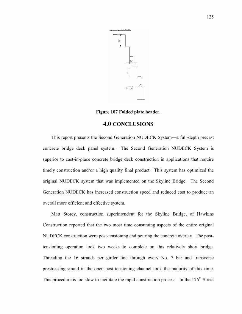
125
Figure 107 Folded plate header.
4.0 CONCLUSIONS
This report presents the Second Generation NUDECK System—a full-depth precast
concrete bridge deck panel system. The Second Generation NUDECK System is
superior to cast-in-place concrete bridge deck construction in applications that require
timely construction and/or a high quality final product. This system has optimized the
original NUDECK system that was implemented on the Skyline Bridge. The Second
Generation NUDECK has increased construction speed and reduced cost to produce an
overall more efficient and effective system.
Matt Storey, construction superintendent for the Skyline Bridge, of Hawkins
Construction reported that the two most time consuming aspects of the entire original
NUDECK construction were post-tensioning and pouring the concrete overlay. The post-
tensioning operation took two weeks to complete on this relatively short bridge.
Threading the 16 strands per girder line through every No. 7 bar and transverse
prestressing strand in the open post-tensioning channel took the majority of this time.
This procedure is too slow to facilitate the rapid construction process. In the 176th Street

126
over I-80 Bridge, which uses the Second Generation NUDECK, the practice of threading
the post-tensioning strands through the middle of the deck is eliminated by laying the
strands on top of the girder before placing the deck panels. This in itself greatly
improves the speed of construction.
A concrete overlay also detracts from rapid construction. The time spent on pouring
and curing the concrete overlay is equal to the time spent pouring and curing a CIP bridge
deck. This is unnecessary as a panel cast with extra depth can be ground to a smooth
roadway profile and still provide adequate corrosion protection to the deck reinforcement.
This design is used for the Second Generation NUDECK on the 176th over I-80 Bridge
applications.
The cost of the original NUDECK system has been reduced by simplifying panel
details. One example of this is increasing the panel length from eight feet to 12 feet.
This will reduce the production, transportation, and construction costs. Another example
of reducing the cost is by designing the precast panels without transverse prestressing.
This allows the contractor to bid on the panel production and the competition will drive
the cost down.
127
REFERENCES
1. “150 ksi All-Thread-Bar,” Williams Form Engineering Corp., 2005, < http: //www.williamsform.com/Threaded_Bars/150_KSI_All-Thread_Bar/150_ksi_all-thread_bar.html>.
2. AASHTO LRFD Bridge Design Specifications, American Association of State Highway and Transportation Officials, Washington, D.C., Third Edition 2004.
3. Abendroth, R.E., "Nominal Strength of Composite Prestressed Concrete Bridge Deck Panels," Journal of Structural Engineering, ASCE, Vol. 121, No. 2, February 1995, pp. 307-318.
4. Babaei, K., Fouladgar, A., and Nicholson, R., “Nighttime Bridge Deck Replacement with Full Depth Precast Concrete Panels at Route 7 over Route 50, Fairfax County, Virginia,” Transportation Research Board, 80th Annual Meeting, January 7-11, 2001, Paper #01-0196, Washington, D.C.
5. Bremner, T.W., and Holm, T.A., “Elastic Compatibility and the Behavior of Concrete,” ACI Journal, V. 83, No. 2, March-April 1986, pp. 244-250.
6. Devalapura, R. K., and Tadros, M. K., “Stress-Strain Modeling of 270-ksi Low-Relaxation Prestressing Strands,” PCI Journal, May/April 1992, pp. 100-106.
7. “Guide Specifications for Polymer Concrete Bridge Deck Overlays”, American Association of State Highway and Transportation Officials, Washington D. C. 1995.
8. Gulyas, R. J., “Precast Bridge Decks: Keyway Grouting Data,” Concrete
International, V. 18, No. 8, August 1996.
9. Holm, T. A., and Bremner, T. W., "State-of-the-Art Report on High-Strength, High-Durability Structural Low-Density Concrete for Applications in Severe Marine Environments," ERDC/SL TR-00-3, US Army Corps of Engineers. Engineer Research and Development Center, Structures Laboratory, Vicksburg, MS, August 2000, 103 pp.
10. Issa, M. A., do Valle, C., Abdalla, H., Islam, S., and Issa, M., “Performance of Transverse Joint Grout Materials in Full-Depth Precast Concrete Bridge Deck Systems,” PCI Journal, July/August 2003, vol. 48, no. 4, pp. 92-103.
11. Issa, M. A., Idriss, A. T., Kaspar, I. I., and Khayyat, S. Y., "Full Depth Precast and Precast, Prestressed Concrete Bridge Deck Panels," PCI Journal, Vol. 40, No. 1, January-February 1995a, pp. 59-80.
12. Issa, M. A., Salas, J. S., Hameed, S. I., “Composite Behavior of Full-Depth Precast Slabs Installed on Precast Prestressed Girders,” submitted for possible publication in the PCI Journal, 2005.
13. Kropp, P. K., Milinski, E. L., Gulzwiller, M. J., Lee, R. B., "Use Of Precast Prestressed Concrete For Bridge Decks" Joint Highway Research Project conducted by Engineering Experiment Station, Purdue University, in cooperation with the Indiana State Highway Commission and the Federal Highway Administration. Final Report, July, 1975, revised December, 1976.

128
14. Menkulasi, F., and Roberts-Wollman, C. “Behavior of Horizontal Shear Connections for Full-Depth Precast Concrete Bridge Decks on Prestressed I-Girders,” PCI Journal, V. 50, No. 3, May/June 2005, pp. 60-73.
15. Nottingham, D., “Joint Grouting in Alaska Bridges and Dock Decks,” Concrete
International, V. 18, No. 2, February 1996, pp. 45-48.
16. Ozyildirim, C., “Permeability Specifications for High-Performance Concrete Decks” Transportation Research Record 1610, Transportation Research Board, Washington D. C. 1998.
17. PCI Committee on Bridges, "Precast Prestressed Concrete Bridge Deck Panels," PCI Journal, V. 32, No. 2, March-April 1987, pp. 26-45.
18. PCI Subcommittee on Full-Depth Bridge Deck Panels, “State-of-the-Art Report on Full-Depth Precast Concrete Bridge Deck Panels,” submitted for publication, 2006.
19. Py, W. A., Weyers, R. E., Weyers, R. N., Mokarem, D. W., Zemajtis, J., Sprinkel, M. M., Dillard, J. G., “Field Performance of Epoxy Coated Reinforcing Steel in Virginia Bridge Decks”, VTRC 00-R16, Virginia Transportation Research Council, Charlottesville, Virginia, 2000.
20. Report Number PCINER-02-FDPCDS “Design Guidelines Full Depth Precast Concrete Deck Slabs” issued June 2002 by the New England Region of PCI.
21. Slavis, C., "Precast Concrete Deck Reconstruction," PCI Journal, V. 28, No. 4, July-August 1983, pp. 120-135.
22. Sprinkel, M. M., “Deck Protection Systems for Post-Tensioned Segmental Concrete Bridges,” Federal Highway Administration, 2003.
23. Sprinkel, M. M., “Precast Concrete Replacement Slabs for Bridge Decks” Virginia Highway and Transportation Research Council, VHTRC 83-R2. Charlottesville, 1982.
24. Tadros, M. K., and Baishya, M. C., "Rapid Replacement of Bridge Decks," Final Report, 12-41, National Cooperative Highway Research Program, Transportation Research Board, July 1997.
25. Tadros, M. K., and Sun, C., “NU-DECK Precast Deck Panels & Innovative Bridge Research and Construction,” NDOR Project Number SPR-PL-1 (037) P528 & EACNH67114, Final Report, May, 2004.
26. “Tolerances for Precast and Prestressed Concrete Construction,” MNL-135-00, Precast/Prestressed Concrete Institute, 2000.
27. Jenkins, T. D., “Redecking and Widening of the Woodrow Wilson Bridge,” International Symposium on Lightweight Concrete Bridges, September 10, 1996, sponsored by Caltrans and Pacific Custom Materials, Sacramento, CA, 16 pp.
28. Source: Engineering News-Record magazine article "A Quick Switch in the Dark," September 1, 1983.