Second Generation Intact Stability Criteria: on the...
10
52 POLISH MARITIME RESEARCH, No 4/2013 INTRODUCTION The Sub-Committee on Stability and Load Lines and on Fishing Vessels Safety (SLF) of the International Maritime Organization (IMO) has undertaken the development of so- called “Second Generation Intact Stability Criteria” (SGISC) with the intention of providing a new set of rules covering those phenomena which are not properly covered by present, mostly semi-empirical, requirements. The envisioned framework of the SGISC is based on a 3+1 tiers approach, where different dangerous phenomena are treated separately, and where three levels of assessment are considered, with increasing complexity. These three levels are so-called “Level 1 Vulnerability Assessment”, “Level 2 Vulnerability Assessment” and “Direct Stability Assessment”. An additional level, bearing the name of the “Development of Operational Guidance”, is also foreseen for those cases where the danger associated with specific phenomena cannot be controlled only by design countermeasures. In the envisioned structure, a ship sailing in a specific loading condition is expected to be considered as “safe” when at least one of the levels can be passed. Of course, firstly the simpler “vulnerability” levels are expected to be applied (and hopefully fulfilled). In case the vulnerability levels cannot be passed, then the following options are available: - the design is modified; - the loading condition is considered as not acceptable; - the ship is tested at the higher tier(s), i.e. “Direct Stability Assessment”, with possible development of ship-specific “Operational Guidance”. The majority of the ongoing discussion taking place at SLF and in the research community has concentrated so far on the development of vulnerability assessment methodologies, since these methods are expected to be applied to a wide population of ships (see, e.g., [1, 2, 3, 4, 5, 6] and references therein). However, more recently, the discussion has also more directly addressed the “Direct Stability Assessment” (DSA), which is also strictly linked with the development of ship- specific “Operational Guidance”. Key aspects in this discussion can be identified in: - the outline of the characteristics of the codes which are expected to be used at these levels; - the validation of the codes. Regarding the expected characteristics of the codes, the preliminary specifications available in [7] indicate that typical hybrid (blended) simulation codes, following the line initiated in [8], have the characteristics adequate for being considered as suitable tools in this context. Regarding the problem of “validation”, one recent IMO document [9] has put forward a proposal where the “validation” of codes could be split into a “qualitative validation” and Second Generation Intact Stability Criteria: on the validation of codes for direct stability assessment in the framework of an example application Gabriele Bulian, Ph.D., Alberto Francescutto, Prof., University of Trieste, Trieste, Italy ABSTRACT The Sub-Committee on Stability and Load Lines and on Fishing Vessels Safety (SLF) of the International Maritime Organization (IMO) has undertaken the development of so-called “Second Generation Intact Stability Criteria” (SGISC) with the intention of providing a new set of rules covering those phenomena which are not properly covered by present, mostly semi-empirical, requirements. The first two levels of the envisioned 3+1 tiers structure of SGISC are so-called “vulnerability assessment” levels: most of the discussion has so far been dedicated to these levels. At the highest level there is the so-called “Direct Stability Assessment”, which is also strictly linked with the development of ship-specific “Operational Guidance”. Recent discussion on the topic of “Direct Stability Assessment” (DSA) has touched the issue of “validation” of numerical codes to be employed at this level. Stimulated by, and in view of, the ongoing IMO discussion, this paper presents the results of a recent series of experiments in beam waves (mono-/bi- chromatic, irregular) and associated simulations based on a 6-DOF blended code. Nonlinear harmonic and sub-harmonic resonances are observed and simulated. Key words: IMO; large amplitude ship motions; second generation intact stability criteria; nonlinear roll; sub-harmonic resonance; validation POLISH MARITIME RESEARCH 4(80) 2013 Vol 20; pp. 52-61 10.2478/pomr-2013-0041
Transcript of Second Generation Intact Stability Criteria: on the...

52 POLISH MARITIME RESEARCH, No 4/2013
INTRODUCTION
The Sub-Committee on Stability and Load Lines and on Fishing Vessels Safety (SLF) of the International Maritime Organization (IMO) has undertaken the development of so-called “Second Generation Intact Stability Criteria” (SGISC) with the intention of providing a new set of rules covering those phenomena which are not properly covered by present, mostly semi-empirical, requirements.
The envisioned framework of the SGISC is based on a 3+1 tiers approach, where different dangerous phenomena are treated separately, and where three levels of assessment are considered, with increasing complexity. These three levels are so-called “Level 1 Vulnerability Assessment”, “Level 2 Vulnerability Assessment” and “Direct Stability Assessment”. An additional level, bearing the name of the “Development of Operational Guidance”, is also foreseen for those cases where the danger associated with specific phenomena cannot be controlled only by design countermeasures. In the envisioned structure, a ship sailing in a specific loading condition is expected to be considered as “safe” when at least one of the levels can be passed. Of course, firstly the simpler “vulnerability” levels are expected to be applied (and hopefully fulfilled). In case the vulnerability levels cannot be passed, then the following options are available:- the design is modified;- the loading condition is considered as not acceptable;
- the ship is tested at the higher tier(s), i.e. “Direct Stability Assessment”, with possible development of ship-specific “Operational Guidance”.
The majority of the ongoing discussion taking place at SLF and in the research community has concentrated so far on the development of vulnerability assessment methodologies, since these methods are expected to be applied to a wide population of ships (see, e.g., [1, 2, 3, 4, 5, 6] and references therein).
However, more recently, the discussion has also more directly addressed the “Direct Stability Assessment” (DSA), which is also strictly linked with the development of ship-specific “Operational Guidance”. Key aspects in this discussion can be identified in:- the outline of the characteristics of the codes which are
expected to be used at these levels;- the validation of the codes.
Regarding the expected characteristics of the codes, the preliminary specifications available in [7] indicate that typical hybrid (blended) simulation codes, following the line initiated in [8], have the characteristics adequate for being considered as suitable tools in this context.
Regarding the problem of “validation”, one recent IMO document [9] has put forward a proposal where the “validation” of codes could be split into a “qualitative validation” and
Second Generation Intact Stability Criteria: on the validation of codes for direct stability assessment in the framework of an example
applicationGabriele Bulian, Ph.D.,Alberto Francescutto, Prof.,University of Trieste, Trieste, Italy
ABSTRACT
The Sub-Committee on Stability and Load Lines and on Fishing Vessels Safety (SLF) of the International Maritime Organization (IMO) has undertaken the development of so-called “Second Generation Intact Stability Criteria” (SGISC) with the intention of providing a new set of rules covering those phenomena which are not properly covered by present, mostly semi-empirical, requirements. The first two levels of the envisioned 3+1 tiers structure of SGISC are so-called “vulnerability assessment” levels: most of the discussion has so far been dedicated to these levels. At the highest level there is the so-called “Direct Stability Assessment”, which is also strictly linked with the development of ship-specific “Operational Guidance”. Recent discussion on the topic of “Direct Stability Assessment” (DSA) has touched the issue of “validation” of numerical codes to be employed at this level. Stimulated by, and in view of, the ongoing IMO discussion, this paper presents the results of a recent series of experiments in beam waves (mono-/bi-chromatic, irregular) and associated simulations based on a 6-DOF blended code. Nonlinear harmonic
and sub-harmonic resonances are observed and simulated.
Key words: IMO; large amplitude ship motions; second generation intact stability criteria; nonlinear roll; sub-harmonic resonance; validation
POLISH MARITIME RESEARCH 4(80) 2013 Vol 20; pp. 52-6110.2478/pomr-2013-0041
53POLISH MARITIME RESEARCH, No 4/2013
a “quantitative validation”. The former is intended to check that the physics embedded into the simulation code is appropriate for the simulation of the phenomenon under analysis. The latter is intended as a check of the degree of accuracy in the reproduction of the phenomenon. Some validation work directly connected with the development of SGISC can be found in [10]. At the same time, it is to be recalled that work aimed at the validation of codes for intact stability assessment, although not intended for a regulatory context, was carried out on different occasions by the ITTC (particularly since [11] up to the latest [12]). Moreover, a lively discussion on the matter of “Verification&Validation (V&V)” is undergoing, in parallel, in the ship stability community (e.g. [13, 14, 15, 16]). A benchmarking study for parametric roll assessment was also undertaken in the framework of the EU-funded SAFEDOR project [17].
Although validation is a fundamental aspect of Science, where mathematical models are continuously checked against real world phenomena since the time of Galileo Galilei, the matter of validation gets a different flavor when embedded in the rule making process, especially in case of IMO intact stability regulations. Indeed, IMO instruments for intact stability are significantly lacking from the point of view of indications regarding validation of simulation codes, and this can easily be explained by the fact that the use of codes for the simulation of ship dynamics is presently not considered as an option in the majority of IMO stability regulations. Exceptions can be found in case of, e.g. high-speed craft and mobile offshore drilling units. This situation is an evident indicator of the tendency of IMO stability requirements to be quite outdated compared to the general level of knowledge, “with an average time interval of 20 to 30 years between scientific evidence and practical application” [18]. Coming back to the issue of “validation”, although this concept cannot be considered as part of present intact stability rules’ background, it is interesting to underline that, in the process of the development of regulations, it is not uncommon to face the request of IMO Delegations for a proper “validation” of the developed rules. As discussed in [5], “validating a rule” is of course a process simply not possible, since a rule is a combination of a calculation method (“criterion” in SGISC nomenclature), which is a technical aspect which can be potentially validated in some cases, and the setting of a limit value (“standard” in SGISC nomenclature), which is a mainly political decision which cannot be “validated”. The term “validation”, in the IMO discussion, is, therefore, often misused.
Given the described situation, it was of interest to look at the results of a series of beam waves model experiments and associated numerical simulations, from the perspective of the undergoing discussion on “Direct Stability Assessment” approaches. Indeed, for a full Series-60 vessel, some experimental results were available from a previous experimental campaign [19]. More experimental tests have recently been carried out, with the ship in different loading conditions, with the aim of investigating the occurrence of sub-harmonic roll motion in beam waves under multi-frequency excitation (in particular bi-chromatic and irregular waves) [20, 21]. Associated with the experimental results, a series of numerical simulations have been carried out using a developed 6-DOF blended code for large amplitude motions and maneuvering in waves [22], which is based on suitable, in principle, modeling for the type of simulations expected to be necessary for “Direct Stability Assessment”. The availability of simulations and experiments allows to put this material in the perspective of SGISC development, and to provide some feedback for the ongoing discussion.
VALIDATION OF CODES FOR DIRECT STABILITY ASSESSMENT
In the framework of SGISC, at so called “Direct Stability Assessment” (DSA) level, it is expected to use simulation models which are able to reproduce the behavior of the ship in waves, with particular attention to certain phenomena which have been identified as “dangerous” (see also [23]). These phenomena are:- Pure loss of stability;- Parametric rolling;- Surf-riding/Broaching;- Dead-Ship condition;- Excessive accelerations.
Although this list might be incomplete, it covers quite a significant part of dangerous events, if considered separately. It should be said that “Excessive accelerations” is actually something different, since excessive accelerations could occur as a result of different „true” dangerous phenomena (e.g. in dead-ship condition, or during a parametric roll event). This aspect is however not discussed further in this paper.
According to [7], tools expected to be used at the DSA level should be based on “state-of-the-art” methods. Ideally, a general purpose software for large amplitude ship motions simulations in waves should be able to address all the aforementioned phenomena if the ship, loading condition and environmental conditions are such to make one of the above phenomena to appear. It is however known that, in the field of simulation of large amplitude ship motions in waves, it is still necessary to use mathematical models which, although being based on first-principles, need to be complemented by not negligible semi-empirical tuning/corrections/sub-models. This is valid, to a different extent, whatever computational model is used. Of course, the more we move towards the full application of first-principles approaches (this meaning, basically, direct computational fluid dynamics approaches addressing the fluid-structure interaction in waves), the less we need semi-empirical additions to the simulations. However, at the moment of writing, a direct complete computational fluid dynamics approach for the extensive simulation of ship behavior in irregular waves is simply not feasible for practical applications, due to the excessive requirement of computation resources/computational time and also due to numerical issues still waiting to be fully resolved in a mature way. This basically leaves the door open, today, only to “hybrid/blended methods”, where, although in a simplified partially semi-empirical way, the most important characteristics of the problem are taken into account, namely: exact ship geometry, nonlinear rigid body dynamics, forces due to (undisturbed) pressure of waves on the instantaneously submerged hull, radiation and diffraction effects, viscous effects, maneuvering forces, rudder effects, wind actions, etc. Being such type of methods partially semi-empirical means that they are often better suited (tailored) for particular applications and/or ship types. For instance, software tools developed, tested and extensively applied for monohulls can be extremely poor in predictions for multihulls, without proper re-tuning (and/or partial re-development). Moving from the problem of different types of ships to the problem of different types of phenomena, methods which, for instance, are working well for dead-ship condition could be completely unsuitable for simulating, for instance, broaching. In particular this latter comment opens a big question, i.e. whether it is appropriate to develop (strongly) different DSA tools for different phenomena. Tailoring too much a tool for a specific application is, in general, dangerous, because the model could eventually overlook possible dangerous phenomena which were not

54 POLISH MARITIME RESEARCH, No 4/2013
explicitly considered in the original development of the model, but which could nevertheless happen for certain ships. An archetypal example of this issue, relevant for this paper, is the 1-DOF modeling of roll in beam waves. It is of course necessary to develop a model for such condition taking into account the nonlinearities of restoring in waves (say ). It is also known that in several situations (typically beam regular waves with sufficiently large metacentric heights ) even relatively simple nonlinear models provide good predictions if properly used/tuned in their parameters. However, despite possible good performances of the model in the “foreseen” conditions, if the model is developed neglecting the coupling with heave and the relative angle between the ship and the waves, it can completely miss the occurrence of some nonlinear phenomena (see [20, 21, 24, 25]). It is therefore necessary to try to avoid, in the development stage, as many simplifications as possible in order to leave as much of the original physics of the problem embedded in the mathematical model, letting the simulation tool “doing its job” without constraining its behavior. Of course, following this way inevitably increases the complexity of the model and, consequently, the debugging phase, the parameters selection phase, the overall computational time, the skills required for using the model, the possible introduction of “spurious” behaviors, etc. etc. It is therefore always a matter of engineering and scientific judgment to decide the level up to which simplifications can be (should be) carried out without compromising too much the capabilities and the accuracy of the model. In this context the process of “validation” helps in checking, although without necessarily giving a final answer to the question of whether the simplifications have been brought the model too far from the real physics.
Going now to the approach proposed in [9], we will report here the main aspects which are relevant for the present discussion. For more information the reader is referred to the original source [9] as well as to some early feedback [26]. The proposal in [9] regarding DSA tools is based on two main concepts:1) The specification of minimum requirements for the
simulation model;2) The specification of validation requirements for considering
the simulation model suitable for regulatory applications.
The specification of the abovementioned requirements is provided differently for different failure modes with some common requirements. It can be commented that this implicitly means that the proposal in [9] assumes as acceptable the development and subsequent validation of possibly different simulation tools for different dangerous phenomena/conditions.
Before going to specific requirements for dead-ship condition (which is the situation dealt with in the present series of experiments / simulations), it is worth reporting a summary of the generic requirements proposed in [9].
First of all, [9] proposes to use the Airy model for modeling waves. It is worth mentioning here, as a comment, that the Airy model requires proper stretching (e.g. [27, 28, 29]) before being consistently usable for large amplitude motion simulations (e.g. [22, 30]) otherwise the zero-pressure condition at the free surface cannot be properly enforced. The stretching method could be different from code to code.
There are then a couple of interesting and useful reminders/requirements in [9] regarding roll damping and hull forces. These notes remind the developers to avoid possible duplications of effects, a matter which was actually touched in the past in [31]. It is indeed important to avoid the possible (partial) overlapping of different models (e.g. seakeeping and maneuvering models) in the simulation code.
Regarding the specific case of dead-ship condition without considering wind (which is the situation dealt with in the present series of experiments / simulations), minimum requirements in [9] can be summarized as follows, with some comments (see the original text for the exact wording):• At least 5 DOFs should be used (surge can be avoided).
As a comment to this requirement, it could be said that eliminating any DOF is always a “tricky” job. The way to eliminate/constrain DOFs is typically not unique and different developers can follow different approaches (e.g. partial elimination through elastic joints, complete elimination through virtual forces based on analytical conditions, simple dropping of terms in the equations of motions, ...).
• Froude-Krylov and hydrostatic forces should be calculated on the actual underwater hull. It is of course necessary to consider the instantaneous underwater hull, because this is the main source of roll restoring nonlinearities. Also, this approach implicitly introduces some coupling with other DOFs, in particular heave, which is something of interest in the framework of the present study. What should however be commented, is the wording used in [9], which implicitly considers it possible to separate the Froude-Krylov component from the hydrostatic component. While this separation is perfectly suited for linear calculations, where the undisturbed wave pressure field can be separated into the undisturbed calm water hydrostatic pressure and the wave disturbance, this is no longer possible in nonlinear simulations, particularly when considering a non-flat free surface. Trying to keep on using this separation can potentially create consistency issues and unforeseen problems (in case of, e.g., very large waves). For this reason, in nonlinear ship motions simulations, the “Froude-Krylov” pressure should always be considered (or, better, defined) as the total pressure of the undisturbed wave (i.e. without removing the “hydrostatic” component). This is particularly necessary when using stretching approaches as mentioned before. Moreover this would be more easily transferrable to fully nonlinear descriptions of the undisturbed wave pressure field.
• Radiation and diffraction forces should be appropriately considered. The introduction of radiation and diffraction effects, in a simplified way, has always been a struggle for developers. The typically most effective approach (though not necessarily the most correct one) is the introduction of diffraction and radiation terms from linear seakeeping pre-calculation. However, also in this case different developers have used different approaches. Typical different choices are whether to use constant coefficients or embed memory effects through convolution integrals (this latter nowadays considered more suitable, although slower from the computation point of view). A particular issue is associated with the reference system to be used for the calculation of radiation and/or diffraction terms based on the linear theory (body-fixed variables? earth fixed variables? variables in “almost-steadily” translating horizontal system? ...). Moreover, variable speed effects (typically with large drift angles) in the case of convolution-based approaches also represent a modeling issue where different approximations can be considered, which leads to inherently different codes/simulation methods.
• Drift forces (longitudinal, heeling moment, yaw moment) should be based on model test results (CFD can be used if proved to be sufficiently accurate). Open issues are associated with this matter. Drift forces from model tests are often determined in quite “artificial” conditions and

55POLISH MARITIME RESEARCH, No 4/2013
a fundamental issue is how to consistently implement experiment (CFD simulation) data in large amplitude motions simulations. A relevant and instructive example touching a little bit this aspect is the application of the alternative experimental assessment of Weather Criterion through the procedure specified in MSC.1/Circ.1200 [32]. As briefly noted in [33], there is often space for “interpretation” on how to combine experiments, which are typically carried out in a free sinkage&trim condition in calm water, with calculations, which are typically dealing with different conditions, especially when wind forces and drift forces are to be combined. The lack of uniqueness in the modeling of these effects is likely to introduce some “modeling noise”.
In addition to the above topics, the proposal in [9] also touches wind forces and, very briefly, the problem of proper generation of irregular waves.
Regarding requirements for validation, the proposal in [9] introduces the idea of splitting the validation process in two parts, namely:1) “Qualitative validation”;2) “Quantitative validation”.
In addition, the proposal in [9] introduces the idea of having a validation process which is basically “failure-mode specific”, although some validation requirements are specified more generally, in terms of the type of characteristic the model is expected to embed. The introduction of a failure-mode specific validation approach has the pros of being very tailored and effective, but, on the other hand, it potentially opens the door to the possibility of overlooking some phenomena which are not originally intended to be represented by the mathematical model and/or checked through the validation process.
Regarding qualitative validation (limiting to aspects related to dead-ship condition - see [9] for exact wording):• Calculation methods where instantaneous underwater
hull geometry is to be considered, shall be capable of consistently reproduce the angle dependence of roll restoring, roll oscillation frequency (backbone curve) and bending of the roll response curve (in addition variations of stability in waves should be properly handled). Bending of roll response curve in beam waves due to restoring nonlinearities is nowadays well known [34]. The bending of the response curve in beam waves is associated, to a large extent, to nonlinearities of roll restoring (although drifting effects can also be of importance [35]). Moreover, nonlinear roll restoring also introduces a rolling-amplitude dependence of the natural roll oscillation frequency, which can be qualitatively (and partially quantitatively) observed through the analysis of (large-initial-angle) roll decays.
• Heel caused by drift and wind should be reproduced. This is of course necessary whenever ship motions are to be simulated in waves and/or wind.
Regarding quantitative validation (limiting to aspects related to dead-ship condition - see [9] for exact wording):
• Results from experiments carried out according to ITTC guidelines should be considered as "correct values". In [9] it is not reported exactly which procedure should be used, but the relevant procedure for this purpose, as suggested in [26], is likely the procedure given in [36]. It is to be said, however, that the procedure [36] is very qualitative in nature.
• Response curve for synchronous roll is acceptable when differences in rolling amplitude are below [10%] if the rolling amplitude is below the angle of maximum GZ,
and [20%] if the rolling amplitude is above the angle of maximum GZ. Putting sharp quantitative limits is always difficult. In particular, 10% limits can be significantly strict, especially in case of relatively small rolling amplitudes. For instance, in case of a rolling amplitude of 10deg, the limit would be set to 1deg. This value, in some cases, is smaller than the reasonable accuracy for certain instrumentation in dynamic conditions (especially some inertial units strongly based on signal post-processing). Also, in standard experiments, unless the towing tank is very long and/or the absorbing beach is extremely efficient, such an uncertainty in rolling amplitude could easily be due to: transient effects, partial reflection, inaccuracies in wave generation, variability of waves along the tank, reflections from tank’s sides, etc. etc. Also, in some cases, large differences at fixed frequencies can be observed due to the shifting in frequency of the simulated response curve with respect to the experimental response curve, for various reasons, such as: differences, between experiments and simulations, of and radii of inertia, inaccuracies in simulating drift and/or in numerically reproducing experimental drift-constraints, typically soft springs, etc. etc. As a result, percentage values should always be bounded by minimum absolute values, which, from experience, could be of the order of ±2 deg.
• Differences between ensemble estimates of roll variance from experiments and simulations should be not statistically significant at 5% confidence level. On this point, lack of more details prevents a detailed discussion.
Given the general complexity of the problem under analysis (nonlinear ship motions in waves) and of the tools intended to be used for the simulation (blended codes), and considering the need of application in a regulatory framework (for DSA and/or development of operational guidance in the framework of SGISC), it is therefore expectable that a “once for all” validation process will not provide sufficient robustness, so requiring appropriate interaction with the Administrations.
SIMULATION METHOD
Simulations have been carried out using a nonlinear 6-DOF blended simulation code (SHIXDOF - “nonlinear SHIp motion simulation program with siX Degrees Of Freedom”), under development at the University of Trieste [21, 22]. The simulation methodology can be considered to follow the line initiated by [8]. The main characteristics of the simulation method have been described in [21, 22], and here they are reported in view of the undergoing discussion on DSA methods in the development of SGISC [9, 26].
First of all, rigid body motion equations are considered fully nonlinear in six DOFs, using a main state vector expressed in a ship-fixed reference system S:Oxyz. As it is common in maneuvering simulations, the nonlinear rigid-body equations of motions are then supplemented by those necessary to translate and orientate the rigid body with respect to an earth-fixed reference system Σ:Ωζηζ. The system of equations then reads as follows:
(1)

56 POLISH MARITIME RESEARCH, No 4/2013
where the superscript “T” indicates the transpose operator, the prime subscript indicates differentiation with respect to time in the ship-fixed reference system, m [kg] is the ship mass, uO = (u, v, w)T [m/s] is the speed of the centre of the reference system (which does not coincide, in general, with the centre of gravity of the ship), ω = (p, q, r)T [rad/s] is the rigid body angular velocity, xG = (xG, yG, zG)T [m] is the position vector of the centre of gravity in the ship-fixed reference system S:Oxyz, IO [kg·m2] is the tensor of inertia with respect to centre O of the ship-fixed reference system, fext [N] is the total force due to external effects and mext(O) [N·m] is the total moment with respect to O due to external effects. The matrices
(ψ, ϑ, φ) and (ψ, ϑ, φ) are appropriate transformation matrices, depending on the Euler angles ψ [rad] (yaw), ϑ [rad] (pitch) and φ [rad] (roll), which are used to obtain the time derivative of the position of the point O in the earth fixed reference system Σ:Ωζηζ and to get the time derivative of the Euler’s angle from the angular velocity. It can be seen that the system of equations (1) considers the fully nonlinear rigid-body dynamics. As such, the rigid-body dynamical model is suitable to consider all the phenomena of interest in the DSA for SGISC and it is in line with the requirements proposed in [9].
The modeling of external forces is intended to give the code the capability of simulating nonlinear ship maneuvering in regular and irregular waves [21, 22]. The Froude-Krylov pressure (comprising the hydrostatic term) is calculated up to the instantaneous wetted surface of the hull in order to catch the effect of geometrical nonlinearities (in particular nonlinear roll restoring), which is a fundamental requirement to address large amplitude motions (particularly roll) in waves. This characteristic is in line with the requirements proposed in [9]. Using an approach along the line in [27], particular attention was given to embed a suitable stretching of the pressure and particle’s velocity fields in order to guarantee, in particular, zero-pressure at the free surface (see discussion on this issue in [30]). Radiation terms (leading to added mass and wave damping) are based on linear hydrodynamic pre-calculations. In order to allow a quite consistent use of the code in irregular waves and/or in case of non-harmonic responses (e.g. sub-harmonic, ultra-harmonic, chaotic motions), radiation effects are embedded through convolution integrals following [37] and accounting for [38]. The linear maneuvering forces due to lift effects are based on linear derivatives from [39]. The roll moment induced by the maneuvering forces is taken into account. In order to avoid overlapping between the seakeeping and the maneuvering model, added mass terms are supposed to be dealt with by the seakeeping model, and this attention in the modeling takes into account the warnings in [9]. However, when simulating the motions in waves, the drift angle can become quite large. For this reason linear maneuvering forces are reduced at large drift angles taking into account [40]. Moreover, since the flow field in waves is characterized by spatial variability due to wave induced orbital velocities, an “equivalent surge-yaw-sway motion” relative to the water is updated at each simulation time step, in a way similar to [41].
Nonlinear drag terms, which in the modeling mimic nonlinear maneuvering forces, are based on a simplified modeling which accounts for the relative speed between water and instantaneously submerged ship centreplane. The obtained model is basically a simplified cross-flow drag model taking into account the instantaneous relative velocity between the ship and wave particles. This model implicitly introduces a nonlinear roll damping. Additional linear and nonlinear roll damping coefficients can be introduced for tuning purposes. Particular attention is given in setting these coefficients, because roll damping is partially provided, implicitly, by different models (seakeeping model, maneuvering model, simplified cross-flow model, ...). This is true also concerning forward speed lift effects, because additional roll damping is introduced by forward speed effects in sway forces from the maneuvering model. For this reason, coefficients are set, in general, by iterative tuning of simulated roll decays. This process takes into account the warnings in [9]. Finally, constraints can be introduced in different forms. With reference to the topic of the paper, springs can be introduced to limit certain motions (typically lateral drift and/or low frequency yaw). Other characteristics are available (e.g. lifting surfaces, propulsors, ...) which are however not relevant for the topic under discussion. Overall, it can be said that the mathematical modeling embedded in the simulation code is therefore in line with the main specifications in [9].
HULL FORM AND EXPERIMENTAL CONDITIONS
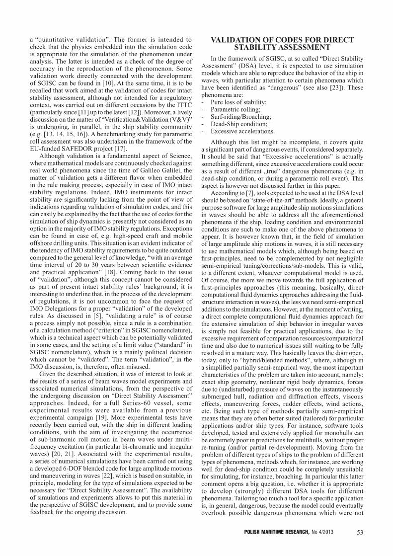
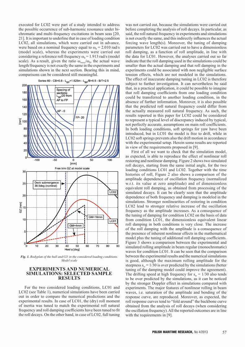
The hull form used in this study is a standard Series 60 with main characteristics reported in Table 1. The bodyplan and the curve in the considered loading conditions are reported in Figure 1. The hull was tested in the past using the loading condition LC01 (see [19]). Recently, additional tests have been carried out in the loading condition LC02, which is characterized by a much lower , and therefore a much more nonlinear . In both cases the is of the “hardening” type (more than linear). All experiments have been carried out at the Hydrodynamic Laboratories of the University of Trieste.
Different types of experimental tests have been carried out for the two considered loading conditions. Letting ω0 the roll natural frequency and:• Loading condition LC01 (large ) [19]. Roll decays,
monochromatic beam waves (ωwave ~ ω0). Model free to drift;
• Loading condition LC02 (small ) [21]. Roll decays, monochromatic beam waves (ωwave ~ 2ω0 ; ωwave ~ 3ω0), bi-chromatic beam waves (ωwave, 2k ~ 2ω0 + ωwave, 3k ~ 3ω0), irregular beam waves (spectral peak frequency ~ 2ω0). Model partially restrained at bow and stern.Tests executed for LC01 were part of a study, associated
with the development of MSC.1/Circ.1200 [32], regarding the application of simplified 1-DOF mathematical models for the analysis and modeling of roll decays and 1:1 resonant roll response under harmonic beam waves. On the other hand, tests
Tab. 1. Main characteristics of the hull form. Nominal data at model scale
Quantity → Mass
[kg]Length
LBP[mm]
BreadthB [mm]
DraughtT [mm]
Dry pitch radius of inertia
Ryy/LBP[nd]
Dry roll radius of inertia
Rxx/B[nd]
[mm]
Natural rollperiod
[s]Config.
↓ Load Cond. ↓
LC0132.5 1625 250 100
N/A N/A 16 1.5 BarehullLC02 0.250 0.362 4 3.1
57POLISH MARITIME RESEARCH, No 4/2013
executed for LC02 were part of a study intended to address the possible occurrence of sub-harmonic resonance under bi-chromatic and multi-frequency excitations in beam seas [20, 21]. It is important to underline that in case of loading condition LC02, all simulations, which were carried out in advance, were based on a nominal frequency equal to ω0 = 2.010 rad/s (model scale), whereas the experiments were carried out considering a reference roll frequency ω0 = 1.913 rad/s (model scale). As a result, given the ratio ωwave/ω0, the actual wave length/frequency is not exactly the same in the experiments and simulations shown in the next section. Bearing this in mind, comparisons can be considered still meaningful.
Fig. 1. Bodyplan of the hull and in the considered loading conditions. Model scale
EXPERIMENTS AND NUMERICAL SIMULATIONS: SELECTED SAMPLE
RESULTS
For the two considered loading conditions, LC01 and LC02 (see Table 1), numerical simulations have been carried out in order to compare the numerical predictions and the experimental results. In case of LC01, the (dry) roll moment of inertia was tuned to match the experimental roll natural frequency and roll damping coefficients have been tuned to fit the roll decays. On the other hand, in case of LC02, full tuning
was not carried out, because the simulations were carried out before completing the analysis of roll decays. In particular, as said, the roll natural frequency in experiments and simulations is not exactly the same, and this indirectly influences the actual forcing wave length(s). Moreover, the tuning of damping parameters for LC02 was carried out to have a dimensionless roll damping, as a function of roll amplitude, in line with the data for LC01. However, the analyses carried out so far indicate that the roll damping used in the simulations could be smaller than the actual damping and that roll damping in the experiments could be associated with non negligible surface tension effects, which are not modeled in the simulations. The effect of inaccurate damping tuning in LC02 is therefore subject to further investigation. It can nevertheless be said that, in a practical application, it could be possible to imagine that roll damping coefficients from one loading condition could be transferred to another loading condition, in the absence of further information. Moreover, it is also possible that the predicted roll natural frequency could differ from the actually measured roll natural frequency. As such, the results reported in this paper for LC02 could be considered to represent a typical level of discrepancy induced by typical, not perfectly accurate, assumptions on main roll coefficients. In both loading conditions, soft springs for yaw have been introduced, but in LC01 the model is free to drift, while in LC02 soft springs prevents also the drift motion in accordance with the experimental setup. Herein some results are reported in view of the requirements proposed in [9].
First of all we want to check that the simulation model, as expected, is able to reproduce the effect of nonlinear roll restoring and nonlinear damping. Figure 2 shows two simulated roll decays, starting from the same initial angle, for the two loading conditions LC01 and LC02. Together with the time histories of roll, Figure 2 also shows a comparison of the amplitude dependence of oscillation frequency (normalized w.r.t. its value at zero amplitude) and of dimensionless equivalent roll damping, as obtained from processing of the simulated decays. It can be clearly seen that the amplitude dependence of both frequency and damping is modeled in the simulations. Stronger nonlinearities of restoring in condition LC02 lead to stronger relative increase of the oscillation frequency as the amplitude increases. As a consequence of the tuning of damping for condition LC02 on the basis of data from condition LC01, the dimensionless equivalent linear roll damping in both conditions is very close. The increase of the roll damping with the amplitude is a consequence of the presence of inherent nonlinear effects in the mathematical model plus the tuning of additional roll damping coefficients. Figure 3 shows a comparison between the experimental and simulated rolling amplitude in beam regular (monochromatic) waves for condition LC01. It can be seen that the comparison between the experimental results and the numerical simulations is good, although the maximum rolling amplitude for the steepness sw = 1/30 is over predicted by the simulations (better tuning of the damping model could improve the agreement). The drifting speed at high frequency for sw = 1/30 also tends to be over predicted by the simulations, as it can be noticed by the stronger Doppler effect in simulations compared with experiments. The major features of nonlinear rolling in beam waves, i.e. saturation of the amplitude and bending of the response curve, are reproduced. Moreover, as expected, the roll response curves tend to “fold around” the backbone curve obtained from the analysis of roll decays (when considering the oscillation frequency). All the reported outcomes are in line with the requirements in [9].

58 POLISH MARITIME RESEARCH, No 4/2013
The experimental tests carried out in the loading condition LC01 have addressed a well known phenomenon, i.e. nonlinear 1:1 resonant roll in regular beam waves. On the other hand, the experiments carried out in the loading condition LC02, which is characterized by a small metacentric height and thus a strongly nonlinear with hardening shape, have instead addressed the occurrence of sub-harmonic roll motion when waves are either bi-chromatic (a useful archetypal model) or irregular (which is a more realistic case). A limited series of tests have also been carried out in mono-chromatic beam waves [21].
In case of bi-chromatic waves [21], two harmonic components have been superimposed, each harmonic with the same ratio between (linear) wave height and wave length (i.e. steepness sw). The frequencies of the two harmonic components, ω2k and ω3k, have been chosen as two and three times, respectively, a reference frequency ωref, which was defined in terms of the roll natural frequency ω0, through a tuning ratio parameter kratio , i.e.:
ωref = kratioω0 ; ω2k = 2ωref ; ω3k = 3ωref (2)
The results from the experiments and the 6-DOF simulations are shown in Figure 4. The roll motion is reported in terms of roll standard deviation since, in principle, the time history could be characterized by multiple frequencies. In reality, due to the dominance of the sub-harmonic response at a frequency equal to ωref, the motion is almost mono-chromatic, hence the amplitude is approximately times the roll standard deviation. The experimentally observed sub-harmonic roll response is reproduced by the simulation model. Discrepancies between the simulated roll motion and the experimental results could partially be due to a not very accurate tuning of roll damping, as already pointed out, and due to the difference in the roll natural frequency ω0 between the experiments and simulations. The bending of the roll response curve observed in the experiments is reproduced by the simulations and the side of the bending, i.e. towards the high frequency region, is consistent with the shape of the roll restoring (hardening type, i.e. more-than-linear type).
Finally, a sample result from tests and simulations in irregular waves is reported in Figure 5. The figure shows
Fig. 2. Simulated roll decays with associated damping/frequency analysis
Fig. 3. Experimental and simulated rolling amplitude in regular beam waves

59POLISH MARITIME RESEARCH, No 4/2013
the roll spectrum as obtained from the experiments and the simulations when the sea spectrum has a Bretschneider shape, with significant wave height 80mm and peak spectral frequency equal to twice the roll natural frequency (simulations: ω0 = 2.010 rad/s ; experiments: ω0 = 1.913 rad/s). It can be seen that the roll motion is completely governed by the sub-harmonic response. This characteristic is observed in experiments and reproduced by simulations. Quantitative agreement between experiments and simulations is good.
It is now worth looking at the results reported in Figure 4 and Figure 5, and link them with the previous discussion regarding the level of simplification which is to be considered as acceptable in the mathematical model for DSA. First of all it must be reported that a relatively “standard” 1-DOF nonlinear roll model based on an absolute angle approach was not able to reproduce the observed sub-harmonic resonances, while a model based on a relative angle approach showed some characteristics of the observed phenomenon, but only from a qualitative point of view [21]. Coming back to the simulations reported in this paper, the mathematical model used in the 6-DOF simulations was developed, originally, without having in mind the possibility of (or need for) simulating the occurrence of sub-harmonic rolling under bi-/multi-chromatic beam sea excitation. Nevertheless, due to the quite general approach, the simulation method has proven to be able to
predict the existence of this type of phenomenon, although this was not in the mind of the developer at the moment of the development. If the modeling had been developed only with the intention of simulating 1:1 resonance in beam regular/irregular waves, it is quite possible that the simplifications introduced for tailoring the model to such application could have led to a simulation tool unable to predict the observed behavior. Therefore, as already said, in case of tools intended for DSA application, it is often better (necessary) to keep the underlying mathematical modeling as general as reasonably possible, letting the simulation tool “doing its job” without constraining its behavior.
CONCLUSIONS
In the framework of the development of “Second Generation Intact Stability Criteria” (SGISC), the IMO has started addressing the topic of “Direct Stability Assessment” (DSA), with particular attention to the characteristics and the validation of those numerical tools which are expected to be used for this purpose. In the 3+1 tiers framework of SGISC (vulnerability level 1 and 2, DSA + ship-specific operational guidance), the DSA level is supposed to be applied only in a relatively small fraction of cases and results from calculations carried out at this level are expected to help, if necessary, in the
Fig. 4. Experimental (left) and simulated (right) rolling amplitude. Bi-chromatic beam waves
Fig. 5. Experimental (left) and simulated (right) roll and sea spectra. Irregular beam waves

60 POLISH MARITIME RESEARCH, No 4/2013
development of ship-specific “Operational Guidance”. Tools to be used at this level are expected to represent the state-of-the-art in the field of simulation of maneuvering and large amplitude ship motions in waves, bearing in mind the need for practical application purposes.
Stimulated by the ongoing discussion, this paper has commented some recent proposals put forward at IMO, linking them with some experimental results and numerical simulations based on a 6-DOF blended code. Topics like the quantitative level of agreement between experiments and simulations, the level of simplification and the risk of inconsistencies in the mathematical models to be used, etc. have been addressed. Several open issues remain on the table, but the example reported in this paper, where a ship with low metacentric height and strongly nonlinear restoring exhibits sub-harmonic resonance in beam bi-chromatic and irregular waves, indicates that too high simplifications in the mathematical models to be used at DSA could lead to the missing of some phenomena, if such phenomena are not in the mind of the developer at the time of developing. For this reason, in case of tools intended for DSA application, it is often better (necessary) to keep the underlying mathematical modeling as general as reasonably possible, letting the simulation tool “doing its job” without constraining its behavior.
The comparison between experiments and simulations, as reported in this paper, has also tried to briefly follow the idea of separating qualitative and quantitative validation, as recently put forward at IMO, for tools to be used at DSA level. The general characteristics of the mathematical model used in the simulation code make it suitable for application at the DSA level and the agreement between the experiments and the simulations has also shown to be in general good.
Acknowledgements
The financial support from “Università degli Studi di Trieste - Finanziamento per Ricercatori di Ateneo (FRA 2011)” is acknowledged. The authors would like to thank Mr. Marco Sinibaldi for the help in the execution of the experimental campaign for loading condition LC02.
REFERENCES
1. SLF54/INF.12: Information collected by the intersessional Correspondence Group on Intact Stability, Submitted by Japan, 11 November 2011, London, UK
2. SLF54/INF.12: Information collected by the intersessional Correspondence Group on Intact Stability, 11 November 2011, IMO, London, UK
3. SLF54/WP.3: Report of the working group (part 1), 19 January 2012, IMO, London, UK
4. Peters, W.S., Belenky, V., Bassler, C., Spyrou, K.: On Vulnerability Criteria for Parametric Roll and Surf-riding, Proc. 12th International Ship Stability Workshop, Washington, USA, June 2011.
5. Bulian, G., Francescutto, A.: Considerations on Parametric Roll and Dead Ship Conditions for the Development of Second Generation Intact Stability Criteria, Proc. 12th International Ship Stability Workshop, Washington, USA, June 2011.
6. Shigunov, V., Rathje, H., El Moctar, O., Altmayer, B.: On the Consideration of Lateral Accelerations in Ship Design Rules, Proc. 12th International Ship Stability Workshop, Washington, USA, June 2011.
7. SLF52/WP.1-Annex 2: Preliminary Specifications for the New Generation Intact Stability Criteria, 28 January 2010, London, UK
8. de Kat, J.O., Paulling, J.R.: The Simulation of Ship Motions and Capsizing in Severe Seas, Trans. SNAME, Vol. 97, 1989, pp. 139-168
9. SLF54/INF.12-Annex 21: United States view on direct stability assessment procedures, Submitted by the United States, 2011
10. Umeda, N., Izawa, S., Sano, H., Kubo, H., Yamane, K., Matsuda, A.: Validation Attempts on Draft New Generation Intact Stability Criteria, Proc. 12th International Ship Stability Workshop, Washington, USA, June 2011.
11. ITTC: Specialist Committee on Prediction of Extreme Ship Motions and Capsizing - Final Report and Recommendations to the 23rd ITTC, Proc. 23rd ITTC, Venice, Volume II, 2002, pp. 619-748
12. ITTC: Specialist Committee on Stability in Waves - Final Report and Recommendations to the 26th ITTC, Proc. 26th ITTC, Rio de Janeiro, Volume II, 2011, pp. 523-560
13. Telste, J. G., Belknap, W. F.: Potential Flow Forces and Moments from Selected Ship Flow Codes in a Set of Numerical Experiments, Carderock Division, Naval Surface Warfare Center Report NSWCCD-50-TR–2008/040, 2008, 15’240 p.
14. Belknap, W, Telste, J.: Identification of Leading Order Nonlinearities from Numerical Forced Motion Experiment Results. Proc. 27th Symposium on Naval Hydrodynamics, Seoul, Korea, 2008
15. Reed, A.M.: A Naval Perspective on Ship Stability, Proc. 10th International Conference on Stability of Ships and Ocean Vehicles (STAB2009), St.Petersburg, 2009, pp.21-44
16. Story, W.R., Xing, Z., Wu, W., McCue, L.: Validation: A Historical Look and Two Suggested Techniques, Proc. ITTC Workshop on Seakeeping - V&V for Nonlinear Seakeeping Analysis, October 2010, Seoul, Korea, pp. 214-246
17. Spanos, D., Papanikolaou, A.: SAFEDOR International Benchmark Study on Numerical Simulation Methods for the Prediction of Parametric Rolling of Ships in Waves, Revision 1.0, 30 June 2009, http://www.naval.ntua.gr/sdl/sibs.
18. Francescutto, A.: Intact Ship Stability: The Way Ahead, Marine Technology, Vol.41, 2004, pp.31-37
19. Tzamtzis, S.: Development and testing of a procedure for the alternative assessment of Weather Criterion on experimental basis, Diploma Thesis, University of Trieste and National Technical University of Athens, Academic Year 2003-2004.
20. Bulian G., Francescutto, A.: Effect of roll modelling in beam waves under multi-frequency excitation, Ocean Engineering, Vol. 38, Issue 13, September 2011, pp. 1448–1463
21. Bulian, G., Francescutto, A., Sinibaldi, M.: Roll motion of a ship with low metacentric height in bi-chromatic beam waves, Proc. of the 11th International Conference on the Stability of Ships and Ocean Vehicles (STAB2012), 23-28 September 2012, Athens, Greece, pp. 187-200
22. Bulian, G., Francescutto, A.: SAFEDOR benchmark on parametric roll - Brief description of the simulation methodology employed in the code SHIXDOF under development at DINMA, Internal Technical Report, Department DINMA, University of Trieste, Trieste, Italy, 2008.
23. IMO: International Code on Intact Stability, 2008 - 2009 Edition, 2009, ISBN 978-92-801-1506-2
24. IMO SLF54/INF.12-Annex 3: On the Consideration of Lateral Accelerations in Ship Design Rules, Submitted by Germany, 2011, (SLF54/INF.12 submitted by Japan)
25. Fujiwara, T, Ikeda, Y.: Effects of roll damping and heave motion on heavy parametric rolling of a large passenger ship in beam waves, Proc. 9th International Ship Stability Workshop, Hamburg, Germany, 2007
26. SLF54/INF.12-Annex 22: Comments on the United States Submission for Direct Stability Assessment Procedures, Submitted by Japan, 2011
27. Wheeler, J.D.: Method for Calculating Forces Produced by Irregular Waves, Offshore Technology Conference, Dallas, Texas, US, Paper No. 1006, 1969
28. Du, S.X., Hudson, D.A., Price, W.G., Temarel, P.: Implicit expressions of static and incident wave pressures over the instantaneous wetted surface of ships, Proc. IMechE Part M: J. Engineering for the Maritime Environment, Vol. 223, 2009, pp. 239-256
29. Faltinsen, O.M.: Sea Loads on Ships and Offshore Structures, Cambridge University Press, 1990

61POLISH MARITIME RESEARCH, No 4/2013
30. Matusiak, J.: On the non-linearities of ship’s restoring and the Froude-Krylov wave load part, 2010, Proc. ITTC Workshop on Seakeeping - V&V for Non-linear Seakeeping Analysis, October 19-21, Seoul National University, Seoul, Korea, pp. 151-159
31. Ayaz, Z., Vassalos, D., Spyrou, K.J.: Manoeuvring behaviour of ships in extreme astern seas, Ocean Engineering, Vol. 33, 2006, pp. 2381-2434
32. IMO MSC.1/Circ.1200: Interim Guidelines for Alternative Assessment of the Weather Criterion, 24 May 2006, London, UK
33. Bulian, G., Francescutto, A., Fucile, F., Cafagna, F., Genuzio, D.H., Maccari, A.: Heeling moment in the alternative assessment of the Weather Criterion: direct experiments and numerical simulations, Proc. 4th International Maritime Conference on Design for Safety and 3rd Workshop on Risk-Based Approaches in the Marine Industries - Part I, 18-20 October 2010, Trieste, Italy, pp. 107-121
34. Francescutto, A., Serra, A.: Experimental tests on ships with large values of B/T, OG/T and roll period, Proc. 6th International Stability Workshop, New York, 2002
35. Kuroda, T., Ikeda, Y.: Extreme Roll Motion in Wide Frequency Range Due to Drift Motion, Proc. 6th International Stability Workshop, New York, 2002
36. ITTC: Recommended Procedures - Model Tests on Intact Stability - 7.5-02-07-04.1”, 2008
37. Cummins, W.E.: The Impulse Response Function and Ship Motions, Schiffstechnik, Vol. 47, 1962, pp. 101-109
38. Bailey, P.A., Price, W.G., Temarel, P.: A Unified Mathematical Model Describing The Manoeuvring of a Ship Travelling in a Seaway”, Trans. RINA, 1998, Vol. 140, pp. 131-149
39. Clarke, D., Gedling, P., Hine, G., “The Application of Manoeuvring Criteria in Hull Design Using Linear Theory”, Trans. RINA, Vol. 125, 1983, pp. 45-68
40. Karasuno, K., Okano, S., Miyoshi, J., Maekawa, K.: Predictions of ship’s hull hydrodynamic forces and maneuvering motions at slow speed based on a component-type mathematical model, Proc. MARSIM2003, Kanazawa, Japan, 25-28 August, 2003, RC-4-(1-11)
41. Artyszuk, J.: A Non-Uniform Current in Ship Manoeuvring, Proc. MARSIM2006 - International Conference on Marine Simulation and Ship Manoeuvrability, Terschelling, the Netherlands, June, 2006
CONTACT WITH THE AUTHORSGabriele Bulian, Ph.D.
Alberto Francescutto, Prof.Department of Engineering and Architecture
University of TriesteVia A. Valerio, 10
34127 Trieste, ITALYe-mail: [email protected] ; [email protected]