Second Generation - aulavirtual.fio.unam.edu.ar
14
10.2 / Cellular NetWork GeNeratioNs 317 channels carry the conversations in analog using frequency modulation (FM). Simple FDMA is used to provide multiple access. Control information is also sent on the conversation channels in bursts as data. This number of channels is inadequate for most major markets, so some way must be found either to use less bandwidth per conversation or to reuse frequencies. Both approaches have been taken in the vari- ous approaches to 1G telephony. For AMPS, frequency reuse is exploited. Second Generation First-generation cellular networks, such as AMPS, quickly became highly popular, threatening to swamp available capacity. Second-generation systems (2G) were developed to provide higher-quality signals, higher data rates for support of digital services, and greater capacity. Key differences between 1G and 2G networks include: • Digital traffic channels: The most notable difference between the two gen- erations is that 1G systems are almost purely analog, whereas 2G systems are digital. In particular, 1G systems are designed to support voice channels using FM; digital traffic is supported only by the use of a modem that converts the digital data into analog form. 2G systems provide digital traffic channels. These systems readily support digital data; voice traffic is first encoded in digi- tal form before transmitting. • Encryption: Because all of the user traffic, as well as control traffic, is digitized in 2G systems, it is a relatively simple matter to encrypt all of the traffic to prevent eavesdropping. All 2G systems provide this capability, whereas 1G systems send user traffic in the clear, providing no security. • Error detection and correction: The digital traffic stream of 2G systems also lends itself to the use of error detection and correction techniques, such as those discussed in Chapters 6 and 16. The result can be very clear voice reception. • Channel access: In 1G systems, each cell supports a number of channels. At any given time a channel is allocated to only one user. 2G systems also provide multiple channels per cell, but each channel is dynamically shared by a num- ber of users using TDMA (time-division multiple access) or CDMA (code division multiple access). Third Generation The objective of the third generation (3G) of wireless communication is to provide fairly high-speed wireless communications to support multimedia, data, and video in addition to voice. The ITU’s International Mobile Telecommunications for the year 2000 (IMT-2000) initiative has defined the third-generation capabilities as follows: • Voice quality comparable to the public switched telephone network • 144 kbps data rate available to users in high-speed motor vehicles over large areas • 384 kbps available to pedestrians standing or moving slowly over small areas • Support (to be phased in) for 2.048 Mbps for office use Objetivos. +Calidad. Voz Digital +Tasa de Tx +Capacidad +Servicios. canal compartido por TDMA CDMA Objetivos: +Velocidad Soporte de: Multimedia. Datos Videos Servicios de comunicaciones personales (PCS, Personal Communications Services) Red de comunicaciones personales (PNS, Personal Network Services) Cel: Pequeño, Liviano, bajo consumo! CDMA: Cada dispositivo está diseñado específicamente para trabajar con un proveedor de red específico. Significa que los teléfonos celulares están vinculados a un operador y su red. Entonces, si decides cambiar de proveedor, tienes que comprar un teléfono móvil nuevo o pedir que te den tu teléfono desbloqueado para tu proveedor actual. Los teléfonos móviles con red CDMA no utilizan tarjetas SIM Ver comentario al pié de la pagina sobre CDMA 2da Generación. IS-95 (de Interim Standard 95, o "estándar interno 95") es un estándar de telefonía móvil celular basado en tecnología CDMA. También conocido por su denominación comercial cdmaOne, fue desarrollado por la compañía norteamericana Qualcomm. A partir de 1990 se han desarrollado y desplegado diferentes sistemas de segunda generación. Emplea el método de multiplexación CDMA por el que todas las estaciones transmiten en la misma banda de frecuencias. La separación entre usuarios se realiza usando códigos ortogonales que se eliminan al ser multiplicados entre sí. Las secuencias binarias se recuperan en el móvil únicamente usando el mismo código que se usó en la estación base. Estándares 2da G: GSM CDMA ó IS-95 TDMA ó IS-136 Sistema Global de Comunicaciones Móviles (GSM):fue desarrollado para proporcionar una tecnología común de segunda generación,GSM consigió imponerse a IS-95 2da Gen. En puja IS-95, GSM, IS--136 +fácil si es digital. 2000 hace 20 años 1990 hace 30 años ver que la tasa varia dependiendo de la velocidad de movimiento. + de 2 veces! 2da Generación:
Transcript of Second Generation - aulavirtual.fio.unam.edu.ar

10.2 / Cellular NetWork GeNeratioNs 317
channels carry the conversations in analog using frequency modulation (FM). Simple FDMA is used to provide multiple access. Control information is also sent on the conversation channels in bursts as data. This number of channels is inadequate for most major markets, so some way must be found either to use less bandwidth per conversation or to reuse frequencies. Both approaches have been taken in the vari-ous approaches to 1G telephony. For AMPS, frequency reuse is exploited.
Second Generation
First-generation cellular networks, such as AMPS, quickly became highly popular, threatening to swamp available capacity. Second-generation systems (2G) were developed to provide higher-quality signals, higher data rates for support of digital services, and greater capacity. Key differences between 1G and 2G networks include:
• Digital traffic channels: The most notable difference between the two gen-erations is that 1G systems are almost purely analog, whereas 2G systems are digital. In particular, 1G systems are designed to support voice channels using FM; digital traffic is supported only by the use of a modem that converts the digital data into analog form. 2G systems provide digital traffic channels. These systems readily support digital data; voice traffic is first encoded in digi-tal form before transmitting.
• Encryption: Because all of the user traffic, as well as control traffic, is digitized in 2G systems, it is a relatively simple matter to encrypt all of the traffic to prevent eavesdropping. All 2G systems provide this capability, whereas 1G systems send user traffic in the clear, providing no security.
• Error detection and correction: The digital traffic stream of 2G systems also lends itself to the use of error detection and correction techniques, such as those discussed in Chapters 6 and 16. The result can be very clear voice reception.
• Channel access: In 1G systems, each cell supports a number of channels. At any given time a channel is allocated to only one user. 2G systems also provide multiple channels per cell, but each channel is dynamically shared by a num-ber of users using TDMA (time-division multiple access) or CDMA (code division multiple access).
Third Generation
The objective of the third generation (3G) of wireless communication is to provide fairly high-speed wireless communications to support multimedia, data, and video in addition to voice. The ITU’s International Mobile Telecommunications for the year 2000 (IMT-2000) initiative has defined the third-generation capabilities as follows:
• Voice quality comparable to the public switched telephone network
• 144 kbps data rate available to users in high-speed motor vehicles over large areas
• 384 kbps available to pedestrians standing or moving slowly over small areas
• Support (to be phased in) for 2.048 Mbps for office use
Objetivos.+Calidad.Voz Digital+Tasa de Tx+Capacidad+Servicios.
canal compartido porTDMACDMA
Objetivos:+Velocidad Soporte de:
Multimedia.DatosVideos
Servicios de comunicaciones personales (PCS, Personal Communications Services)Red de comunicaciones personales (PNS, Personal Network Services)
Cel: Pequeño, Liviano, bajo consumo!
CDMA: Cada dispositivo está diseñado específicamente para trabajar con un proveedor de red específico. Significa que los teléfonos celulares están vinculados a un operador y su red. Entonces, si decides cambiar de proveedor, tienes que comprar un teléfono móvil nuevo o pedir que te den tu teléfono desbloqueado para tu proveedor actual.Los teléfonos móviles con red CDMA no utilizan tarjetas SIM
Ver comentario al pié de la pagina sobre CDMA
2da Generación.IS-95 (de Interim Standard 95, o "estándar interno 95") es un estándar de telefonía móvil celular basado en tecnología CDMA. También conocido por su denominación comercial cdmaOne, fue desarrollado por la compañía norteamericana Qualcomm.A partir de 1990 se han desarrollado y desplegado diferentes sistemas de segunda generación.Emplea el método de multiplexación CDMA por el que todas las estaciones transmiten en la misma banda de frecuencias. La separación entre usuarios se realiza usando códigos ortogonales que se eliminan al ser multiplicados entre sí. Las secuencias binarias se recuperan en el móvil únicamente usando el mismo código que se usó en la estación base.
Estándares 2da G:GSMCDMA ó IS-95TDMA ó IS-136
Sistema Global de Comunicaciones Móviles (GSM):fue desarrollado para proporcionar una tecnología común de segunda generación,GSM consigió imponerse a IS-95
2da Gen.En pujaIS-95, GSM, IS--136
+fácil si esdigital.
2000 hace 20 años
1990hace 30 años
ver que la tasa variadependiendo de la velocidadde movimiento.+ de 2 veces!
2da Generación:

318 ChaPter 10 / Cellular Wireless NetWorks
• Symmetrical and asymmetrical data transmission rates
• Support for both packet-switched and circuit-switched data services
• An adaptive interface to the Internet to reflect efficiently the common asym-metry between inbound and outbound traffic
• More efficient use of the available spectrum in general
• Support for a wide variety of mobile equipment
• Flexibility to allow the introduction of new services and technologies
The dominant technology for 3G systems is CDMA. Although three different CDMA schemes have been adopted, they share the following design features:
• Bandwidth: An important design goal for all 3G systems is to limit channel usage to 5 MHz. There are several reasons for this goal. On the one hand, a bandwidth of 5 MHz or more improves the receiver’s ability to resolve mul-tipath when compared to narrower bandwidths. On the other hand, available spectrum is limited by competing needs, and 5 MHz is a reasonable upper limit on what can be allocated for 3G. Finally, 5 MHz is adequate for support-ing data rates of 144 and 384 kHz, the main targets for 3G services.
• Chip rate: Given the bandwidth, the chip rate depends on desired data rate, the need for error control, and bandwidth limitations. A chip rate of 3 Mcps or more is reasonable given these design parameters.
• Multirate: The term multirate refers to the provision of multiple fixed-data-rate logical channels to a given user, in which different data rates are provided on different logical channels. Further, the traffic on each logical channel can be switched independently through the wireless and fixed networks to different destinations. The advantage of multirate is that the system can flexibly support multiple simultaneous applications from a given user and can efficiently use available capacity by only providing the capacity required for each service.
Fourth Generation
The evolution of smartphones and cellular networks has ushered in a new gen-eration of capabilities and standards, which is collectively called 4G. 4G systems provide ultra-broadband Internet access for a variety of mobile devices including laptops, smartphones, and tablets. 4G networks support Mobile Web access and high-bandwidth applications such as high-definition mobile TV, mobile video con-ferencing, and gaming services.
These requirements have led to the development of a fourth generation (4G) of mobile wireless technology that is designed to maximize bandwidth and through-put while also maximizing spectral efficiency. The ITU has issued directives for 4G networks. According to the ITU, an IMT-Advanced (or 4G) cellular system must fulfill a number of minimum requirements, including the following:
• Be based on an all-IP packet switched network.
• Support peak data rates of up to approximately 100 Mbps for high-mobility mobile access and up to approximately 1 Gbps for low-mobility access such as local wireless access.
Código de División de Acceso Múltiple (CDMA)
3 Mega chips x seg.
Objetivo de 4Gmaximizar el ancho de banda y poner al mismo tiempo que maximiza la eficiencia espectral
red de conmutación de paquetes capa 3, IP
100Mbps moviendose mucho1Gbps moviendose poco
Foto de una portada de revista de Agosto de 1996, hace 24 añosVinton Cerf , fue co-diseñador del protocolo TCP/IP.Miembro de la Junta directiva de Internet Corporation for Assigned Names and Numbers (ICANN)
UMTS: Sistema universal de telecomunicaciones móviles (Universal Mobile Telecommunications System o UMTS) es una de las tecnologías usadas por los móviles de tercera generación, sucesora de GPRS, debido a que la tecnología GPRS (evolución de GSM) propiamente dicha no podía evolucionar para prestar servicios considerados de tercera generación.
https://socialgeek.co/moviles/evolucion-celulares/amp/ Aqui se ve una lista de equipos a lo largo del tiempo.
Mejoras por 5M-resolver Multipath.-se puede ofrecer 144 y 384
2010 hace 10 años
+eficiencia espectral+ de 50 veces la velocidadde 3g
Basado en IP!
IP en cualiquier cosa

10.2 / Cellular NetWork GeNeratioNs 319
• Dynamically share and use the network resources to support more simultane-ous users per cell.
• Support smooth handovers across heterogeneous networks.
• Support high quality of service for next-generation multimedia applications.
In contrast to earlier generations, 4G systems do not support traditional circuit-switched telephony service, providing only IP telephony services. And, as may be observed in Table 10.1, the spread spectrum radio technologies that characterized 3G systems are replaced in 4G systems by OFDMA (orthogonal fre-quency-division multiple access) multicarrier transmission and frequency-domain equalization schemes.
Figure 10.9 illustrates several major differences between 3G and 4G cellular networks. As shown in Figure 10.9a, the connections between base stations and switching offices in 3G networks are typically cable-based, either copper or fiber wires. Circuit switching is supported to enable voice connections between mobile users and phones connected to the PSTN. Internet access in 3G networks may also be routed through switching offices. By contrast, in 4G networks, IP telephony is the norm as are IP packet-switched connections for Internet access. These are enabled by wireless connections, such as fixed broadband wireless access (BWA)
Switching office
WiMax fixedBWA
Wire/fiber network
Switching office
Wire/fiber network
Wire/fiber network
(a) Third-generation (3G) cellular network
(b) Fourth-generation (4G) cellular network
Figure 10.9 Third vs. Fourth Generation Cellular Networks
Admite traspasos fluidos en redes heterogéneas.
Boardband wireless access
Canales compartidos dinámicamente => +usuarios por celda.
chau telefonoconmutcioncircuitos
Medio guiado
Medio No guiado con WiMAX
320 ChaPter 10 / Cellular Wireless NetWorks
WiMAX, between base stations and switching offices (Figure 10.9b). Connections among mobile users with 4G-capable smartphones may never be routed over cable-based, circuit-switched connections—all communications between them can be IP-based and handled by wireless links. This setup facilitates deployment of mobile-to-mobile video call/video conferencing services and the simultaneous delivery of voice and data services (such as Web browsing while engaged in a phone call). 4G mobile users can still connect with 3G network users and PSTN subscribers over cable/fiber circuit-switched connections between the switching offices.
10.3 Lte-advanced
Two candidates emerged for 4G standardization. One is known as Long Term Evolution (LTE), which has been developed by the Third Generation Partnership Project (3GPP), a consortium of Asian, European, and North American telecommuni-cations standards organizations. The other effort is from the IEEE 802.16 committee, which has developed standards for high-speed fixed wireless operations known as WiMAX (described in Chapter 18). The committee has specified an enhancement of WiMAX to meet 4G needs. The two efforts are similar in terms of both perfor-mance and technology. Both are based on the use of orthogonal frequency-division multiple access (OFDMA) to support multiple access to network resources. WiMAX uses a pure OFDMA approach for both uplink (UL) and downlink (DL). LTE uses pure OFDMA on the downlink and a technique that is based on OFDMA but offers enhanced power efficiency for the uplink. While WiMAX retains a role as the tech-nology for fixed broadband wireless access, LTE has become the universal standard for 4G wireless. For example, all of the major carriers in the United States, including AT&T and Verizon, have adopted a version of LTE based on frequency-division duplex (FDD), whereas China Mobile, the world’s largest telecommunication car-rier, has adopted a version of LTE based on time-division duplex (TDD).
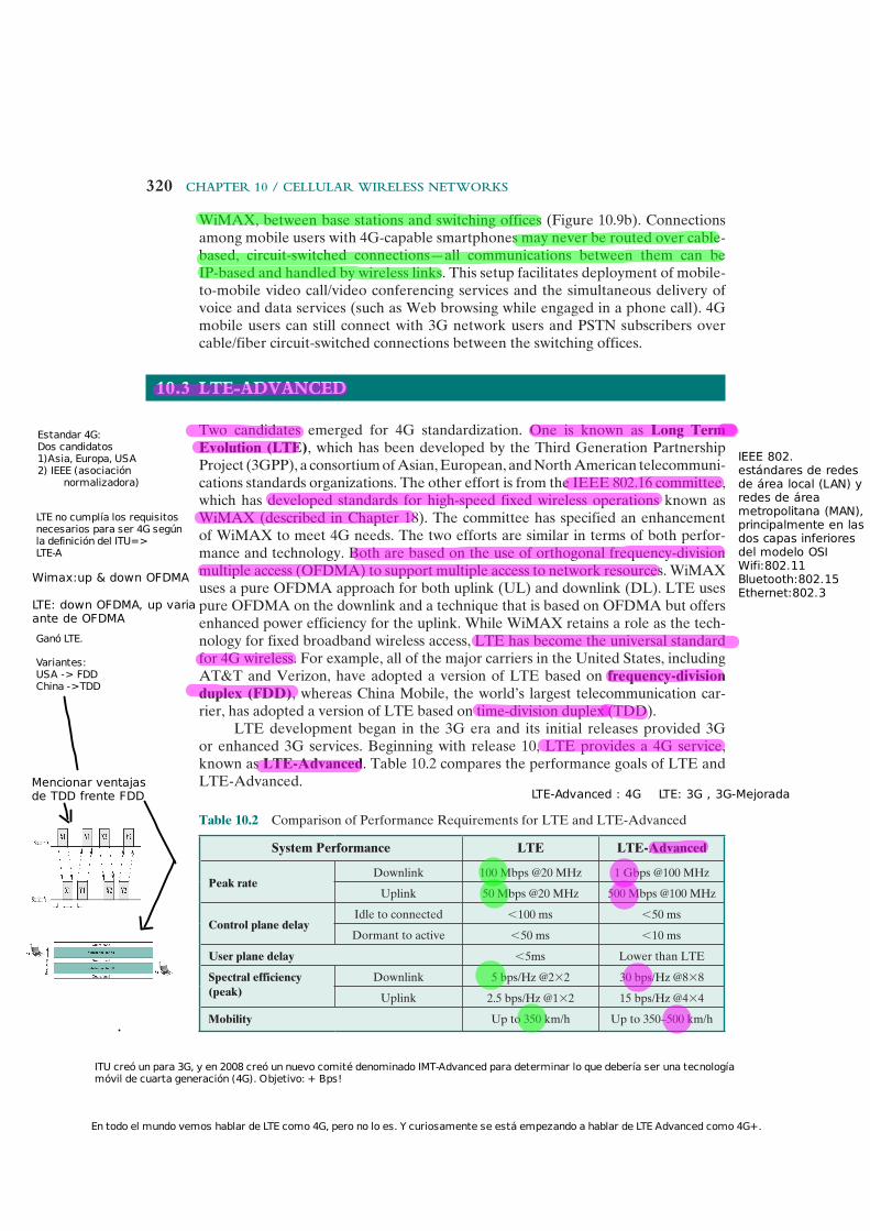
LTE development began in the 3G era and its initial releases provided 3G or enhanced 3G services. Beginning with release 10, LTE provides a 4G service, known as LTE-Advanced. Table 10.2 compares the performance goals of LTE and LTE-Advanced.
Table 10.2 Comparison of Performance Requirements for LTE and LTE-Advanced
System Performance LTE LTE-Advanced
Peak rateDownlink 100 Mbps @20 MHz 1 Gbps @100 MHz
Uplink 50 Mbps @20 MHz 500 Mbps @100 MHz
Control plane delayIdle to connected 6 100 ms 6 50 ms
Dormant to active 6 50 ms 6 10 ms
User plane delay 6 5ms Lower than LTE
Spectral efficiency (peak)
Downlink 5 bps/Hz @2 * 2 30 bps/Hz @8 * 8
Uplink 2.5 bps/Hz @1 * 2 15 bps/Hz @4 * 4
Mobility Up to 350 km/h Up to 350–500 km/h
Ganó LTE.
Variantes:USA -> FDDChina ->TDD
Estandar 4G:Dos candidatos1)Asia, Europa, USA2) IEEE (asociación
normalizadora)
ITU creó un para 3G, y en 2008 creó un nuevo comité denominado IMT-Advanced para determinar lo que debería ser una tecnología móvil de cuarta generación (4G). Objetivo: + Bps!
LTE no cumplía los requisitos necesarios para ser 4G según la definición del ITU=>LTE-A
En todo el mundo vemos hablar de LTE como 4G, pero no lo es. Y curiosamente se está empezando a hablar de LTE Advanced como 4G+.
IEEE 802.estándares de redes de área local (LAN) yredes de área metropolitana (MAN),principalmente en lasdos capas inferiores del modelo OSIWifi:802.11Bluetooth:802.15Ethernet:802.3
Wimax:up & down OFDMA
LTE: down OFDMA, up variaante de OFDMA
Mencionar ventajasde TDD frente FDD LTE-Advanced : 4G LTE: 3G , 3G-Mejorada

10.3 / lte-advaNCed 321
The specification for LTE-Advanced is immense. This section provides a brief overview.
LTE-Advanced Architecture
Figure 10.10 illustrates the principal elements in an LTE-Advanced network. The heart of the system is the base station, designated evolved NodeB (eNodeB). In LTE, the base station is referred to as NodeB. The key differences between the two base station technologies are:
• The NodeB station interface with subscriber stations (referred to as user equipment (UE)) is based on CDMA, whereas the eNodeB air interface is based on OFDMA.
• eNodeB embeds its own control functionality, rather than using an RNC (Radio Network Controller) as does a NodeB.
DonoreNodeB
Evolvedpacket
core MME
HSSSGW
PGW
UE
eNodeB = evolved NodeBHSS = home subscriber serverMME = mobility management entityPGW = packet data network (PDN) gatewayRN = relay nodeSGW = serving gatewayUE = user equipment control traffic
data traffic
RN UE
Internet
Figure 10.10 LTE-Advanced Configuration Elements
CDMA
Las empresas de telefonía Telecom Personal, Movistar y Claro ya ofrecen el servicio 4G LTE con cobertura en las principales ciudades del país operando con las frecuencias 1900 MHz (Banda 2), 1700 MHz (para subida) y 2100 MHz (para descarga) (AWS banda 4), de 2600 MHz (Banda 7), y de 700 MHz (APT banda 28). Con estas bandas las empresas brindan LTE Advanced en algunas ciudades. En Argentina Movistar y Claro ofrecen Voz sobre LTE.
Nodo Repetidor.
En LTE-A la estación base se denomina:eNodeB :evolved Node B, en LTE se denomina NodeB
CDMAC de Code.
OFDMA
en el contorno de la celda:+Interferencia- Señal..Solución : pongo Relay Node (RN).!
UE ve a RN como un eNodeB
ve a RNcomo UE
UE : User Equipment
EPC

322 ChaPter 10 / Cellular Wireless NetWorks
relayIng Another key element of an LTE-Advanced cellular network is the use of relay nodes (RNs). As with any cellular system, an LTE-Advanced base station experiences reduced data rates near the edge of its cell, due to lower signal levels and higher interference levels. Rather than use smaller cells, it is more efficient to use small relay nodes, which have a reduced radius of operation compared to an eNodeB, distributed around the periphery of the cell. A UE near an RN communi-cates with the RN, which in turn communicates with the eNodeB.
An RN is not simply a signal repeater. Instead the RN receives, demodulates, and decodes the data and applies error correction as needed, and then transmits a new signal to the base station, referred to in this context as a donor eNodeB. The RN functions as a base station with respect to its communication with the UE and as a UE with respect to its communication with the eNodeB.
• The eNodeB S RN transmissions and RN S eNodeB transmissions are carried out in the DL frequency band and UL frequency band, respectively, for FDD systems.
• The eNodeB S RN transmissions and RN S eNodeB transmissions are carried out in the DL subframes of the eNodeB and RN and UL subframes of the eNodeB and RN, respectively, for TDD systems.
Currently, RNs use inband communication, meaning that the RN–eNodeB interface uses the same carrier frequency as the RN–UE interface. This creates an interference issue that can be described as follows. If the RN receives from the eNodeB and transmits to the UE at the same time, it is both transmitting and receiving on the downlink channel. The RN’s transmission will have a much greater signal strength than the DL signal arriving from the eNodeB, making it very difficult to recover the incoming DL signal. The same problem occurs in the uplink direction. To overcome this difficulty, frequency resources are partitioned as follows:
• eNodeB S RN and RN S UE links are time-division multiplexed in a single frequency band and only one is active at any one time.
• RN S eNodeB and UE S RN links are time-division multiplexed in a single frequency band and only one is active at any one time.
evolved packet core The operator, or carrier, network that interconnects all of the base stations of the carrier is referred to as the evolved packet core (EPC). Traditionally, the core cellular network was circuit switched, but for 4G the core is entirely packet switched. It is based on IP and supports voice connections using voice over IP (VoIP).
Figure 10.10 illustrates the essential components of the EPC:
• Mobility management entity (MME): The MME deals with control signaling related to mobility and security. The MME is responsible for the tracking and the paging of UEs in idle-mode.
• Serving gateway (SGW): The SGW deals with user data transmitted and received by UEs in packet form, using IP. The SGW is the point of interconnect
RN es mas que unrepetidor de señal.
Core conmutación de paquetes!
Core basado en IP =>soporta VoIP
10.3 / lte-advaNCed 323
between the radio side and the EPC. As its name indicates, this gateway serves the UE by routing the incoming and outgoing IP packets. It is the anchor point for the intra-LTE mobility (i.e., in case of handover between eNodeBs). Thus, packets can be routed from an eNodeB to an eNodeB in another area via the SGW, and can also be routed to external networks such as the Internet (via the PGW).
• Packet data network gateway (PGW): The PGW is the point of interconnect between the EPC and external IP networks such as the Internet. The PGW routes packets to and from the external networks. It also performs various functions such as IP address/IP prefix allocation and policy control and charging.
• Home subscriber server (HSS): The HSS maintains a database that contains user-related and subscriber-related information. It also provides support func-tions in mobility management, call and session setup, user authentication, and access authorization.
Figure 10.10 shows only a single instance of each configuration element. There are, of course, multiple eNodeBs, and multiple instances of each of the EPC ele-ments. And there are many-to-many links between eNodeBs and MMEs, between MMEs and SGWs, and between SGWs and PGWs.
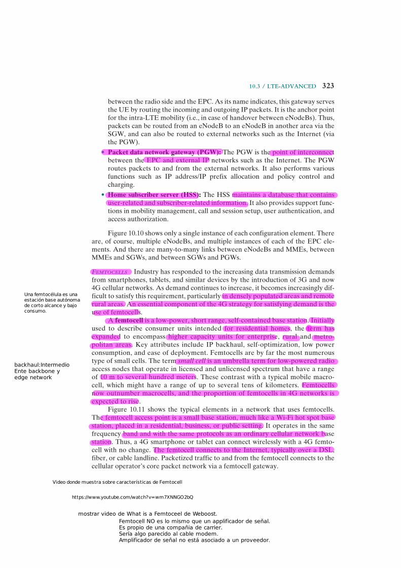
FeMtocells Industry has responded to the increasing data transmission demands from smartphones, tablets, and similar devices by the introduction of 3G and now 4G cellular networks. As demand continues to increase, it becomes increasingly dif-ficult to satisfy this requirement, particularly in densely populated areas and remote rural areas. An essential component of the 4G strategy for satisfying demand is the use of femtocells.
A femtocell is a low-power, short range, self-contained base station. Initially used to describe consumer units intended for residential homes, the term hasexpanded to encompass higher capacity units for enterprise, rural and metro-politan areas. Key attributes include IP backhaul, self-optimization, low power consumption, and ease of deployment. Femtocells are by far the most numerous type of small cells. The term small cell is an umbrella term for low-powered radio access nodes that operate in licensed and unlicensed spectrum that have a range of 10 m to several hundred meters. These contrast with a typical mobile macro-cell, which might have a range of up to several tens of kilometers. Femtocells now outnumber macrocells, and the proportion of femtocells in 4G networks is expected to rise.
Figure 10.11 shows the typical elements in a network that uses femtocells. The femtocell access point is a small base station, much like a Wi-Fi hot spot base station, placed in a residential, business, or public setting. It operates in the same frequency band and with the same protocols as an ordinary cellular network base station. Thus, a 4G smartphone or tablet can connect wirelessly with a 4G femto-cell with no change. The femtocell connects to the Internet, typically over a DSL, fiber, or cable landline. Packetized traffic to and from the femtocell connects to the cellular operator’s core packet network via a femtocell gateway.
Una femtocélula es una estación base autónoma de corto alcance y bajo consumo.
https://www.youtube.com/watch?v=wm7XNNGO2bQ
Video donde muestra sobre características de Femtocell
backhaul:IntermedioEnte backbone yedge network
Femtocell NO es lo mismo que un applificador de señal.Es propio de una compañia de carrier.Sería algo parecido al cable modem.Amplificador de señal no está asociado a un proveedor.
mostrar video de What is a Femtoceel de Weboost.

324 ChaPter 10 / Cellular Wireless NetWorks
LTE-Advanced Transmission Characteristics
LTE-Advanced relies on two key technologies to achieve high data rates and spectral efficiency: orthogonal frequency-division multiplexing (OFDM) and multiple-input multiple-output (MIMO) antennas. Both of these technologies are explored in Chapter 17.
For the downlink, LTE-Advanced uses OFDMA and for the uplink SC-OFDM (single-carrier OFDM).
OFDM signals have a high peak-to-average power ratio (PAPR), requiring a linear power amplifier with overall low efficiency. This is a poor quality for bat-tery-operated handsets. While complex, SC-FDMA has a lower PAPR and is better suited to portable implementation.
Fdd and tdd LTE-Advanced has been defined to accommodate both paired spectrum for frequency-division duplex and unpaired spectrum for time-division duplex operation. Both LTE TDD and LTE FDD are being widely deployed as each form of the LTE standard has its own advantages and disadvantages. Table 10.3 compares key characteristics of the two approaches.
FDD systems allocate different frequency bands for uplink and downlink trans-missions. The UL and DL channels are usually grouped into two blocks of contiguous
DSL/FTTH line
Base station(radius: several km)
Femtocellgateway
Femtocellaccess point
(radius: several m)
Operatormacrocell
system
Internet
Figure 10.11 The Role of Femtocells

10.3 / lte-advaNCed 325
channels (paired spectrum) that are separated by a guard band of a number of vacant radio frequency (RF) channels for interference avoidance. Figure 10.12a illustrates a typical spectrum allocation in which user i is allocated a pair of channels Ui and Di with bandwidths WU and WD. The frequency offset, WO, used to separate the pair of channels should be large enough for the user terminal to avoid self-interference among the links because both links are simultaneously active.
For TDD, the UL and DL transmissions operate in the same band but alter-nate in the time domain. Capacity can be allocated more flexibly than with FDD. It
Table 10.3 Characteristics of TDD and FDD for LTE-Advanced
Parameter LTE-TDD LTE-FDD
Paired spectrum Does not require paired spectrum as both transmit and receive occur on the same channel.
Requires paired spectrum with sufficient frequency separation to allow simultane-ous transmission and reception.
Hardware cost Lower cost as no diplexer is needed to isolate the transmitter and receiver. As cost of the UEs is of major importance because of the vast numbers that are produced, this is a key aspect.
Diplexer is needed and cost is higher.
Channel reciprocity Channel propagation is the same in both directions which enables trans-mit and receive to use one set of parameters.
Channel characteristics are different in the two directions as a result of the use of dif-ferent frequencies.
UL/DL asymmetry It is possible to dynamically change the UL and DL capacity ratio to match demand.
UL/DL capacity is determined by fre-quency allocation set out by the regulatory authorities. It is therefore not possible to make dynamic changes to match capacity. Regulatory changes would normally be required and capacity is normally allocated so that it is the same in either direction.
Guard period/guard band
Guard period required to ensure uplink and downlink transmissions do not clash. Large guard period will limit capacity. Larger guard period normally required if distances are increased to accommodate larger propagation times.
Guard band required to provide sufficient isolation between uplink and down-link. Large guard band does not impact capacity.
Discontinuous transmission
Discontinuous transmission is required to allow both uplink and downlink transmissions. This can degrade the performance of the RF power ampli-fier in the transmitter.
Continuous transmission is required.
Cross slot interference
Base stations need to be synchronized with respect to the uplink and down-link transmission times. If neighboring base stations use different uplink and downlink assignments and share the same channel, then interference may occur between cells.
Not applicable

326 ChaPter 10 / Cellular Wireless NetWorks
is a simple matter of changing the proportion of time devoted to UL and DL within a given channel.
carrIer aggregatIon Carrier aggregation is used in LTE-Advanced in order to increase the bandwidth, and thereby increase the bit rates. Since it is impor-tant to keep backward compatibility with LTE the aggregation is of LTE carriers. Carrier aggregation can be used for both FDD and TDD. Each aggregated carrier is referred to as a component carrier, CC. The component carrier can have a band-width of 1.4, 3, 5, 10, 15, or 20 MHz and a maximum of five component carriers can be aggregated, hence the maximum aggregated bandwidth is 100 MHz. In FDD, the number of aggregated carriers can be different in DL and UL. However, the number of UL component carriers is always equal to or lower than the number of DL component carriers. The individual component carriers can also be of different bandwidths. When TDD is used the number of CCs and the bandwidth of each CC are the same for DL and UL.
Figure 10.13a illustrates how three carriers, each of which is suitable for a 3G station, are aggregated to form a wider bandwidth suitable for a 4G station. As Figure 10.13b suggests, there are three approaches used in LTE-Advanced for aggregation:
• Intra-band contiguous: This is the easiest form of LTE carrier aggregation to implement. Here, the carriers are adjacent to each other. The aggregated channel can be considered by the terminal as a single enlarged channel from the RF viewpoint. In this instance, only one transceiver is required within the subscriber station. The drawback of this method is the need to have a contigu-ous spectrum band allocation.
(a) FDD
(b) TDD
U1
WU
D1 D2 D3 D4U2 U3 U4
Channel 1 Channel 2 Channel 3 Channel 4
WU + WD
Guard band WGUplink band Downlink band
WD
Figure 10.12 Spectrum Allocation for FDD and TDD
+AB=>+bps
CC:component Carrier
Retro Compatibilidad..
1
3 Enfoques de LTEAggregation.
Tomo varios canales contíguos de 3G para hacer uno de 4.Tengo compatibilidad con 3G.

10.3 / lte-advaNCed 327
• Intra-band noncontiguous: Multiple CCs belonging to the same band are used in a noncontiguous manner. In this approach, the multicarrier signal cannot be treated as a single signal and therefore multiple transceivers are required. This adds significant complexity, particularly to the UE where space, power, and cost are prime considerations. This approach is likely to be used in countries where spectrum allocation is noncontiguous within a single band or when the middle carriers are in use by other subscribers.
• Inter-band noncontiguous: This form of carrier aggregation uses different bands. It will be of particular use because of the fragmentation of bands—some of which are only 10 MHz wide. For the UE it requires the use of multiple transceivers within the single item, with the usual impact on cost, performance, and power.
Carriercomponent
Frequency
3G Station
Carriercomponent
Carriercomponent
Carriercomponent
Carriercomponent
3G Station
(a) Logical view of carrier aggregation
(b) Types of carrier aggregation
Band A
4G station
3G Station
Carriercomponent
Carriercomponent
Band A
Intra-bandcontiguous
Intra-bandnoncontiguous
Inter-bandnoncontiguous Band A Band B
Carriercomponent
Carriercomponent
Figure 10.13 Carrier Aggregation
2
3
canales no contiguos=>multiples transeivers!=> + complejo , +$
en la misma banda
en distintas bandascanales no contiguos
+costos, +complejo , + caro

328 ChaPter 10 / Cellular Wireless NetWorks
10.4 recOmmended reading
[BERT94] and [ANDE95] are instructive surveys of cellular wireless propagation effects. [TANT98] contains reprints of numerous important papers dealing with CDMA in cellular networks. [OJAN98] provides an overview of key technical design considerations for 3G systems. Another useful survey is [ZENG00].
Worthwhile introductions to LTE-Advanced include [FREN13], [BAKE12], [PARK11], and [GHOS10]. [CHAN06] explores the use of FDD and TDD in 4G networks. [IWAM10] provides an overview of LTE-Advanced carrier aggregation. [BAI12] discusses LTE-Advanced modem design issues.
ANDE95 Anderson, J.; Rappaport, T.; and Yoshida, S. “Propagation Measurements and Models for Wireless Communications Channels.” IEEE Communications Magazine, January 1995.
BAI12 Bai, D., et al. “LTE-Advanced Modem Design: Challenges and Perspectives.” IEEE Communications Magazine, February 2012.
BAKE12 Baker, M. “From LTE-Advanced to the Future.” IEEE Communications Magazine, February 2012.
BERT94 Bertoni, H.; Honcharenko, W.; Maciel, L.; and Xia, H. “UHF Propagation Prediction for Wireless Personal Communications.” Proceedings of the IEEE, September 1994.
CHAN06 Chan, P., et al. “The Evolution Path of 4G Networks: FDD or TDD?” IEEE Communications Magazine, December 2006.
FREN13 Frenzel, L. “An Introduction to LTE-Advanced: The Real 4G.” Electronic Design, February 2013.
GHOS10 Ghosh, A., et al. “LTE-Advanced: Next-Generation Wireless Broadband Technology.” IEEE Wireless Communications, June 2010.
IWAM10 Iwamura, M., et al. “Carrier Aggregation Framework in 3GPP LTE-Advanced.” IEEE Communications Magazine, August 2010.
OJAN98 Ojanpera, T., and Prasad, G. “An Overview of Air Interface Multiple Access for IMT-2000/UMTS.” IEEE Communications Magazine, September 1998.
PARK11 Parkvall, S.; Furuskar, A.; and Dahlman, E. “Evolution of LTE toward IMT-Advanced.” IEEE Communications Magazine, February 2011.
TANT98 Tantaratana, S., and Ahmed, K., eds. Wireless Applications of Spread Spectrum Systems: Selected Readings. Piscataway, NJ: IEEE Press, 1998.
ZENG00 Zeng, M.; Annamalai, A.; and Bhargava, V. “Harmonization of Global Third-generation Mobile Systems.” IEEE Communications Magazine, December 2000.

10.5 / key terms, revieW QuestioNs, aNd Problems 329
10.5 key terms, review QuestiOns, and PrObLems
Key Terms
adaptive equalizationAdvanced Mobile Phone
Service (AMPS)base stationcarrier aggregationcellular networkcode division multiple
access (CDMA)diffractiondiversitydonor eNodeBevolved NodeB (eNodeB)evolved packet core (EPC)fadingfast fadingfemtocellsflat fading
first-generation (1G) network
forward error correctionfourth-generation (4G)
networkfrequency diversityfrequency-division duplex
(FDD)frequency reusehandoffhome subscriber server
(HSS)long-term evolution (LTE)LTE-Advancedmobile radiomobility management entity
(MME)
packet data network gateway (PGW)
reflectionrelay node (RN)relayingreuse factorscatteringsecond-generation (2G)
networkselective fadingserving gateway (SGW)slow fadingspace diversitythird-generation (3G)
networktime-division duplex (TDD)
Review Questions
10.1 What geometric shape is used in cellular system design?10.2 What is the principle of frequency reuse in the context of a cellular network?10.3 List five ways of increasing the capacity of a cellular system.10.4 Explain the paging function of a cellular system.10.5 What is fading?10.6 What is the difference between diffraction and scattering?10.7 What is the difference between fast and slow fading?10.8 What is the difference between flat and selective fading?10.9 What are the key differences between first- and second-generation cellular systems?
10.10 What are some key characteristics that distinguish third-generation cellular systems from second-generation cellular systems?
Problems
10.1 The first-generation AMPS system used a frequency allotment of K frequencies and a basic cell pattern of N = 7. What is the maximum number of frequency bands per cell?
10.2 Consider four different cellular systems that share the following characteristics. The frequency bands are 825 to 845 MHz for mobile unit transmission and 870 to 890 MHz

330 ChaPter 10 / Cellular Wireless NetWorks
for base station transmission. A duplex circuit consists of one 30-kHz channel in each direction. The systems are distinguished by the reuse factor, which is 4, 7, 12, and 19, respectively.a. Suppose that in each of the systems, the cluster of cells (4, 7, 12, 19) is duplicated
16 times. Find the number of simultaneous communications that can be supported by each system.
b. Find the number of simultaneous communications that can be supported by a single cell in each system.
c. What is the area covered, in cells, by each system?d. Suppose the cell size is the same in all four systems and a fixed area of 100 cells is
covered by each system. Find the number of simultaneous communications that can be supported by each system.
10.3 Describe a sequence of events similar to that of Figure10.6 fora. a call from a mobile unit to a fixed subscriberb. a call from a fixed subscriber to a mobile unit
10.4 An analog cellular system has a total of 33 MHz of bandwidth and uses two 25-kHz simplex (one-way) channels to provide full-duplex voice and control channels.a. What is the number of channels available per cell for a frequency reuse factor of
(1) 4 cells, (2) 7 cells, and (3) 12 cells?b. Assume that 1 MHz is dedicated to control channels but that only one control
channel is needed per cell. Determine a reasonable distribution of control channels and voice channels in each cell for the three frequency reuse factors of part (a).
10.5 A cellular system uses FDMA with a spectrum allocation of 12.5 MHz in each direc-tion, a guard band at the edge of the allocated spectrum of 10 kHz, and a channel bandwidth of 30 kHz. What is the number of available channels?
10.6 For a cellular system, FDMA spectral efficiency is defined as ha = BcNT
Bw where
Bc = channel bandwidthBw = total bandwidth in one directionNT = total number of voice channels in the covered area
What is an upper bound on ha?