Sec 1.9 CC Geometry Quadrilateral Properties Name · 2013-08-30 · Sec 1.9 CC Geometry –...
16
Sec 1.9 CC Geometry – Quadrilateral Properties Name: Investigation #1 : (From the State Math Unit 1 Frameworks) Construct two segments of different length that are perpendicular bisectors of each other. Connect the four end points to form a quadrilateral. What names can be used to describe the quadrilaterals formed using these constraints? Justify your answer. Open Geometer’s Sketchpad. Using the segment tool, , create a segment as shown at in the picture. While the segment is still highlighted, select M idpoint from the C onstruct menu at the top. Switch back to the selection tool, , and highlight the segment and midpoint only as shown in the picture at the right. With the segment and midpoint highlighted select Perpendicular Line from the C onstruct menu at the top (shown at the right). Switch to the point tool, and place a new point on the newly created perpendicular line. p.38 M. Winking (Section 1-9)
Transcript of Sec 1.9 CC Geometry Quadrilateral Properties Name · 2013-08-30 · Sec 1.9 CC Geometry –...

Sec 1.9 CC Geometry – Quadrilateral Properties Name:
Investigation #1 :
(From the State Math Unit 1 Frameworks) Construct two segments of different length that are
perpendicular bisectors of each other. Connect the four end points to form a quadrilateral. What
names can be used to describe the quadrilaterals formed using these constraints? Justify your
answer.
Open Geometer’s Sketchpad.
Using the segment tool, , create a segment as shown at in the picture.
While the segment is still highlighted, select
Midpoint from the Construct menu at the top.
Switch back to the selection tool, , and highlight the segment and midpoint only as shown in the picture at the right.
With the segment and midpoint highlighted select
Perpendicular Line from the Construct menu at
the top (shown at the right).
Switch to the point tool, and place a new point on the newly created perpendicular line.
p.38
M. Winking (Section 1-9)

Switch back to the selection tool, , and double
click on the original segment ( in the picture at the right) until it flashes as shown.
Next, be sure to just highlight the point on the perpendicular line (point D in the diagram at the
right) and select Reflect from the Transform
menu.
Using the selection tool, , click in a blank space in the sketch and then, select only the
perpendicular line ( shown in the diagram).
With the line selected, select Hide
Perpendicular Line from the Display menu.
p.39
M. Winking (Section 1-9)

Reconnect the points on the perpendicular line
using the segment tool, , and also connect each consecutive endpoint to form a quadrilateral as shown at the right.
Try using the mouse to click and drag each of the endpoints of the quadrilateral to see what effects it has on the figure.
Since we constructed the midpoint, used a perpendicular line, and a reflection which angles must be right angles and which segments must be congruent in the figure at the right? Use congruent marks to show which must be congruent and right angle marks to show which angles are right angels.
Which triangles must be congruent in the diagram using SAS?
Which additional sides must be congruent using CPCTC?
What type of quadrilateral must this be?
p.40
M. Winking (Section 1-9)

Investigation #2
(From the State Math Unit 1 Frameworks) Repeat investigation #1 with two congruent segments.
Connect the four end points to form a quadrilateral. What names can be used to describe the
quadrilaterals formed using these constraints? Justify your answer.
Open Geometer’s Sketchpad.
Using the segment tool, , create a segment as shown at in the picture.
While the segment is still highlighted,
select Midpoint from the Construct
menu at the top.
Using the Circle Tool, , create a circle that has a radius starting with the midpoint (point C) and ending at one of the endpoints (point B). It is important in this step you click on center point C and drag and drop the edge of the circle on point B with the cursor (so that the circle is linked to the point C and B).
Switch back to the selection tool, . You may need to deselect everything first. Do this by clicking in a blank are of the sketch. Then, highlight the segment and midpoint only as shown in the picture at the right.
With the segment and midpoint
highlighted select Perpendicular Line
from the Construct menu at the top
(shown at the right).
p.41
M. Winking (Section 1-9)

Using the selection tool, , click on the intersection point of the circle and the perpendicular line to create the actual intersection points.
First, click in a blank area to deselect everything. Then, highlight the perpendicular line and the circle only (leaving the all of the points and original segment unselected). Finally, select Hide Path Objects
Reconnect the points on the perpendicular
line using the segment tool, , and also connect each consecutive endpoint to form a quadrilateral as shown at the right. p.42
M. Winking (Section 1-9)

Try using the mouse to click and drag each of the endpoints of the quadrilateral to see what effects it has on the figure.
Since we constructed the midpoint, used a perpendicular line, and the circle tool which angles must be right angles and which segments must be congruent in the figure at the right? Use congruent marks to show which must be congruent and right angle marks to show which angles are right angels.
Which triangles must be congruent in the diagram using SAS?
Which additional sides must be congruent using CPCTC?
What type of quadrilateral must this be?
p.43
M. Winking (Section 1-9)

Investigation #3
(From the State Math Unit 1 Frameworks) Construct two segments that bisect each other but are
not perpendicular. Connect the four end points to form a quadrilateral. What names can be used to
describe the quadrilaterals formed using these constraints? Justify your answer.
Open Geometer’s Sketchpad.
Using the segment tool, , create a segment as shown at in the picture.
While the segment is still highlighted,
select Midpoint from the Construct
menu at the top.
Using the Circle Tool, , create a circle that has a radius starting with the midpoint (point C) and ending at one of a newly created point (point D).
First click and hold down on the
segment tool, and select the ray
tool, as shown at the right.
Create ray by first clicking on point D and then point C as shown at the right.
p.44
M. Winking (Section 1-9)

Using the selection tool, , click on
the intersection of the new ray and the circle to create a point at the intersection.
First, click in a blank area to deselect
everything. Then, highlight the ray and the circle only (leaving the all of the points and original segment unselected).
Finally, select Hide Path Objects from
the Display menu.
Reconnect the points on the perpendicular line using the segment
tool, , and also connect each consecutive endpoint to form a quadrilateral as shown at the right.
p.45
M. Winking (Section 1-9)

Try using the mouse to click and drag each of the endpoints of the quadrilateral to see what effects it has on the figure.
Since we constructed the midpoint, used the circle tool which angles must be congruent angles and which segments must be congruent in the figure at the right? Use congruent marks to show which must be congruent and right angle marks to show which angles are right angels.
Which triangles must be congruent in the diagram using SAS?
Which additional sides must be congruent using CPCTC?
What type of quadrilateral must this be?
p.46
M. Winking (Section 1-9)
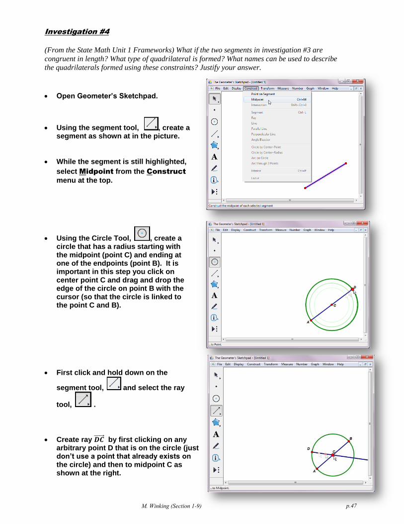
Investigation #4
(From the State Math Unit 1 Frameworks) What if the two segments in investigation #3 are
congruent in length? What type of quadrilateral is formed? What names can be used to describe
the quadrilaterals formed using these constraints? Justify your answer.
Open Geometer’s Sketchpad.
Using the segment tool, , create a segment as shown at in the picture.
While the segment is still highlighted,
select Midpoint from the Construct
menu at the top.
Using the Circle Tool, , create a circle that has a radius starting with the midpoint (point C) and ending at one of the endpoints (point B). It is important in this step you click on center point C and drag and drop the edge of the circle on point B with the cursor (so that the circle is linked to the point C and B).
First click and hold down on the
segment tool, and select the ray
tool, .
Create ray by first clicking on any arbitrary point D that is on the circle (just don’t use a point that already exists on the circle) and then to midpoint C as shown at the right.
p.47
M. Winking (Section 1-9)

Using the selection tool, , click on
the intersection of the new ray and the circle to create a point at the intersection.
First, click in a blank area to deselect
everything. Then, highlight the ray and the circle only (leaving the all of the points and original segment unselected).
Finally, select Hide Path Objects from
the Display menu.
Reconnect the points on the line
using the segment tool, , and also connect each consecutive endpoint to form a quadrilateral as shown at the right.
p.48
M. Winking (Section 1-9)
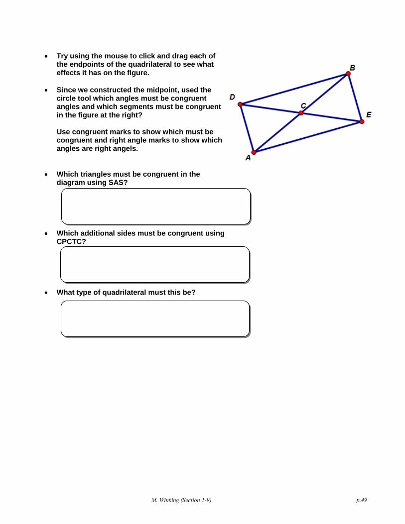
Try using the mouse to click and drag each of the endpoints of the quadrilateral to see what effects it has on the figure.
Since we constructed the midpoint, used the circle tool which angles must be congruent angles and which segments must be congruent in the figure at the right? Use congruent marks to show which must be congruent and right angle marks to show which angles are right angels.
Which triangles must be congruent in the diagram using SAS?
Which additional sides must be congruent using CPCTC?
What type of quadrilateral must this be? p.49
M. Winking (Section 1-9)

Investigation #5
(From the State Math Unit 1 Frameworks) Draw a segment and mark the midpoint. Now construct
a segment that is perpendicular to the first segment at the midpoint but is not bisected by the
original segment. Connect the four end points to form a quadrilateral. What names can be used to
describe the quadrilaterals formed using these constraints? Justify your answer.
Open Geometer’s Sketchpad.
Using the segment tool, , create a segment as shown at in the picture.
While the segment is still highlighted,
select Midpoint from the Construct
menu at the top.
Switch back to the selection tool, , and highlight the segment and midpoint only as shown in the picture at the right.
With the segment and midpoint highlighted
select Perpendicular Line from the
Construct menu at the top (shown at the
right).
Switch to the point tool, and place two new points on opposite sides of the newly created perpendicular line
p.50
M. Winking (Section 1-9)

Using the selection tool, , click in a blank area to deselect everything. Then,
highlight the line only (leaving the all of the points and original segment
unselected). Finally, select Hide
Perpendicular Line from the Display
menu.
Reconnect the points on the line
using the segment tool, , and also connect each consecutive endpoint to form a quadrilateral as shown at the right.
Try using the mouse to click and drag each of the endpoints of the quadrilateral to see what effects it has on the figure.
Since we constructed the midpoint, used the circle tool which angles must be congruent angles and which segments must be congruent in the figure at the right?
Use congruent marks to show which must be congruent and right angle marks to show which angles are right angels.
Which triangles must be congruent in the diagram using SAS?
Which additional sides must be congruent using CPCTC?
What type of quadrilateral must this be? p.51
M. Winking (Section 1-9)

Investigation #6
(From the State Math Unit 1 Frameworks) Draw a segment and mark the midpoint. Now construct
a segment that is perpendicular to the first segment at the midpoint but is not bisected by the
original segment. Connect the four end points to form a quadrilateral. What names can be used to
describe the quadrilaterals formed using these constraints? Justify your answer.
Open Geometer’s Sketchpad.
Using the segment tool, , create a segment as shown at in the picture.
While the segment is still highlighted,
select Midpoint from the Construct
menu at the top.
First click and hold down on the
segment tool, and select the ray
tool, .
Create ray by first clicking on any arbitrary point D out in the blank part of the sketch and then to midpoint C as shown at the right.
Next, using the point tool, , add a
point to the ray (preferably on the new point should be on the opposite
side of segment from point D.
p.52
M. Winking (Section 1-9)

Using the selection tool, , click in a blank area to deselect everything. Then,
highlight the ray only (leaving the all of the points and original segment
unselected). Finally, select Hide Ray
from the Display menu.
Reconnect the points on the segment
line using the segment tool, , and also connect each consecutive endpoint to form a quadrilateral as shown at the right.
Try using the mouse to click and drag each of the endpoints of the quadrilateral to see what effects it has on the figure.
Since we constructed the midpoint, used the circle tool which angles must be congruent angles and which segments must be congruent in the figure at the right?
Use congruent marks to show which must be congruent and right angle marks to show which angles are right angels.
Which triangles must be congruent in the diagram using SAS?
Which additional sides must be congruent using CPCTC?
What type of quadrilateral must this be? p.53
M. Winking (Section 1-9)