Seat Belt Assemblies
33
TECHNICAL STANDARDS DOCUMENT No. 209, Revision 2R Seat Belt Assemblies The text of this document is based on Federal Motor Vehicle Safety Standard No. 209, Seat Belt Assemblies, as published in the U.S. Code of Federal Regulations, Title 49, Part 571, revised as of October 1, 2012. Publication Date: Effective Date: Mandatory Compliance Date: June 19, 2013 June 19, 2013 December 19, 2013 (Ce document est aussi disponible en français)
Transcript of Seat Belt Assemblies
TECHNICAL STANDARDS DOCUMENT No. 209, Revision 2R
Seat Belt Assemblies
The text of this document is based on Federal Motor Vehicle Safety Standard No. 209, Seat Belt Assemblies, as published in
the U.S. Code of Federal Regulations, Title 49, Part 571, revised as of October 1, 2012.
Publication Date: Effective Date: Mandatory Compliance Date:
June 19, 2013 June 19, 2013
December 19, 2013
(Ce document est aussi disponible en français)
Seat Belt Assemblies TSD No. 209, Revision 2R
Introduction As defined by section 12 of the Motor Vehicle Safety Act, a Technical Standards Document (TSD) is a document that reproduces an enactment of a foreign government (e.g. a Federal Motor Vehicle Safety Standard issued by the U.S. National Highway Traffic Safety Administration). According to the Act, the Motor Vehicle Safety Regulations may alter or override some provisions contained in a TSD or specify additional requirements; consequently, it is advisable to read a TSD in conjunction with the Act and its counterpart Regulation. As a guide, where the corresponding Regulation contains additional requirements, footnotes indicate the amending subsection number.
TSDs are revised from time to time in order to incorporate amendments made to the reference document, at which time a Notice of Revision is published in the Canada Gazette, Part I. All TSDs are assigned a revision number, with “Revision 0” designating the original version.
Identification of Changes In order to facilitate the incorporation of a TSD, certain non-technical changes may be made to the foreign enactment. These may include the deletion of words, phrases, figures, or sections that do not apply under the Act or Regulations, the conversion of imperial to metric units, the deletion of superseded dates, and minor changes of an editorial nature. Additions are underlined, and provisions that do not apply are stroked through. Where an entire section has been deleted, it is replaced by: “[CONTENT DELETED]”. Changes are also made where there is a reporting requirement or reference in the foreign enactment that does not apply in Canada. For example, the name and address of the U.S. Department of Transportation are replaced by those of the Department of Transport.
Effective Date and Mandatory Compliance Date Compliance with the requirements of a TSD that is being introduced for the first time is not mandatory until six months after publication in the Canada Gazette, Part II, of the Regulations that incorporate the TSD. In the case of a revision, compliance becomes mandatory six months after publication of the Notice of revision in the Canada Gazette, Part I, as long as the requirements of the previous version continue to be met. Voluntary compliance is permitted as of the Effective Date of the TSD.
Effective: June 19, 2013 i
Seat Belt Assemblies TSD No. 209, Revision 2R
Official Version of Technical Standards Documents The PDF version is a replica of the TSD as published by the Department and is to be used for the purposes of legal interpretation and application.
Effective: June 19, 2013 ii
Seat Belt Assemblies TSD No. 209, Revision 2R
Table of Contents Introduction .......................................................................................................................... i
S1. Purpose and Scope ....................................................................................................... 1
S2. Application ................................................................................................................... 1
S3. Definitions ..................................................................................................................... 1
S4. Requirements ............................................................................................................... 2
S4.1 Untitled .................................................................................................................... 2
S4.2 Requirements for webbing ....................................................................................... 4
S4.3 Requirements for hardware...................................................................................... 5
S4.4 Requirements for assembly performance ................................................................ 9
S4.5 Load-limiter ........................................................................................................... 10
S4.6 Manual belts subject to the crash protection requirements of Standard No. 208 .. 10
S5. Demonstration procedures ........................................................................................ 10
S5.1 Webbing ................................................................................................................. 10
S5.2 Hardware................................................................................................................ 12
S5.3 Assembly performance .......................................................................................... 18
S5.4 Tolerances on angles .............................................................................................. 21
List of Figures Figure 1 — Split Drum Grips to be Used for the Webbing Strength Tests ................. 22
Figure 2 — Hexagonal Bar to be Used for the Abrasion Test ...................................... 23
Figure 3 — Testing of Attachment Bolts ........................................................................ 24
Figure 4 — Testing of Single Attachment Hooks ........................................................... 25
Figure 5 — Testing of the Seat Belt Assembly ............................................................... 26
Figure 6 — Dust Chamber for Retractor Cycling ......................................................... 27
Figure 7 — Testing of Buckle Resistance to Abrasion .................................................. 28
Figure 8 — Acceleration Corridors ................................................................................. 29
Effective: June 19, 2013 iii
Seat Belt Assemblies TSD No. 209, Revision 2R
S1. Purpose and Scope This Technical Standards Document (TSD) standard specifies requirements for seat belt assemblies.
S2. Application [CONTENT DELETED] For applicability, see Schedule III and subsection 209(1) of Schedule IV to the Motor Vehicle Safety Regulations.
S3. Definitions 1 Adjustment hardware means any or all hardware designed for adjusting the size of a seat belt assembly to fit the user, including such hardware that may be integral with a buckle, attachment hardware, or retractor. (Pièces de réglage) 1 Attachment hardware means any or all hardware designed for securing the webbing of a seat belt assembly to a motor vehicle. (Pièces de fixation) 1 Automatic-locking retractor means a retractor incorporating adjustment hardware by means of a positive self-locking mechanism which is capable, when locked, of withstanding restraint forces. (Rétracteur autobloquant) 1 Buckle means a quick release connector which fastens a person in a seat belt assembly. (Attache) 1 Emergency-locking retractor means a retractor incorporating adjustment hardware by means of a locking mechanism that is activated by vehicle acceleration, webbing movement relative to the vehicle, or other automatic action during an emergency and is capable when locked of withstanding restraint forces. (Rétracteur à blocage d’urgence) 1 Hardware means any metal or rigid plastic part of a seat belt assembly. (Pièces) 2 Load-limiter means a seat belt assembly component or feature that controls tension on the seat belt to modulate the forces that are imparted to occupants restrained by the belt assembly during a crash. (Limiteur de charge) 2 Nonlocking retractor means a retractor from which the webbing is extended to essentially its full length by a small external force, which provides no adjustment for assembly length, and which may or may not be capable of sustaining restraint forces at maximum webbing extension. (Rétracteur sans blocage)
1 Please see subsection 2(1) of the Motor Vehicle Safety Regulations (MVSR) for the applicable definition. 2 Please see subsection 2(1) of the MVSR for the applicable definition.
Effective: June 19, 2013 1
Seat Belt Assemblies TSD No. 209, Revision 2R
2 Pelvic restraint means a seat belt assembly or portion thereof intended to restrain movement of the pelvis. (Ceinture sous-abdominale) 2 Retractor means a device for storing part or all of the webbing in a seat belt assembly. (Rétracteur)
Seat back retainer means the portion of some seat belt assemblies designed to restrict forward movement of a seat back. (Dispositif de maintien du dossier) 2 Seat belt assembly means any strap, webbing, or similar device designed to secure a person in a motor vehicle in order to mitigate the results of any accident, including all necessary buckles and other fasteners, and all hardware designed for installing such seat belt assembly in a motor vehicle. (Ceinture de sécurité) 2 Strap means a narrow nonwoven material used in a seat belt assembly in place of webbing. (Courroie) 2 Type 1 seat belt assembly is a lap belt for pelvic restraint. (Ceinture de sécurité de type 1) 2 Type 2 seat belt assembly is a combination of pelvic and upper torso restraints. (Ceinture de sécurité de type 2)
Type 2a shoulder belt is an upper torso restraint for use only in conjunction with a lap belt as a Type 2 seat belt assembly. (Ceinture diagonale de type 2a) 2 Upper torso restraint means a portion of a seat belt assembly intended to restrain movement of the chest and shoulder regions. (Ceinture-baudrier) 2 Webbing means a narrow fabric woven with continuous filling yarns and finished selvages. (Sangle)
S4. Requirements3
S4.1 Untitled
a) [Reserved]
b) Single occupancy. A seat belt assembly shall be designed for use by one, and onlyone, person at any one time.
c) Upper torso restraint. A Type 2 seat belt assembly shall provide upper torso restraintwithout shifting the pelvic restraint into the abdominal region. An upper torsorestraint shall be designed to minimize vertical forces on the shoulders and spine.Hardware for upper torso restraint shall be so designed and located in the seat beltassembly that the possibility of injury to the occupant is minimized. A Type 2a
2 Please see subsection 2(1) of the MVSR for the applicable definition. 3 Please see subsection 209(2) of the MVSR for an additional requirement.
Effective: June 19, 2013 2
Seat Belt Assemblies TSD No. 209, Revision 2R
shoulder belt shall comply with applicable requirements for a Type 2 seat belt assembly in S4.1 to S4.4, inclusive.
d) Hardware. All hardware parts which contact under normal usage a person, clothing,or webbing shall be free from burrs and sharp edges.
e) Release. A Type 1 or Type 2 seat belt assembly shall be provided with a buckle orbuckles readily accessible to the occupant to permit his easy and rapid removal fromthe assembly.4 The buckle release mechanism shall be designed to minimize thepossibility of accidental release. A buckle with a release mechanism in the latchedposition shall have only one opening in which the tongue can be inserted on the endof the buckle designed to receive and latch the tongue.
f) Attachment hardware. A seat belt assembly shall include all hardware necessary forinstallation in a motor vehicle in accordance with SAE Recommended Practice J800c(1973) (incorporated by reference, see the list at Chapter V, Title 49, part § 571.5paragraph (k) of the Code of Federal Regulations). However, seat belt assembliesdesigned for installation in motor vehicles equipped with seat belt assemblyanchorages that do not require anchorage nuts, plates, or washers need not have suchhardware, but shall have 7/16-20 UNF-2A or ½-13 UNC-2A attachment bolts orequivalent metric hardware. The hardware shall be designed to prevent attachmentbolts and other parts from becoming disengaged from the vehicle while in service.Reinforcing plates or washers furnished for universal floor installations shall be ofsteel, free from burrs and sharp edges on the peripheral edges adjacent to the vehicle,at least 1.5 mm in thickness, and at least 2580 mm2 in projected area. The distancebetween any edge of the plate and the edge of the bolt hole shall be at least 15 mm.Any corner shall be rounded to a radius of not less than 6 mm or cut so that no cornerangle is less than 135 degrees and no side is less than 6 mm in length.
g) Adjustment. [CONTENT DELETED]5
h) Webbing. The ends of webbing in a seat belt assembly shall be protected or treated toprevent raveling. The end of webbing in a seat belt assembly having a metal-to-metalbuckle that is used by the occupant to adjust the size of the assembly shall not pull outof the adjustment hardware at maximum size adjustment. Provision shall be made foressentially unimpeded movement of webbing routed between a seat back and seatcushion and attached to a retractor located behind the seat.
i) Strap. A strap used in a seat belt assembly to sustain restraint forces shall complywith the requirements for webbing in S4.2, and if the strap is made from a rigidmaterial, it shall comply with applicable requirements in S4.2, S4.3, and S4.4.
4 Please see subsection 209(8) of the MVSR for a related provision. 5 Please see subsection 209(9) of the MVSR for a related provision and subsections 208(10) to (12) for seat belt fit requirements.
Effective: June 19, 2013 3
Seat Belt Assemblies TSD No. 209, Revision 2R
j) Marking. Each seat belt assembly shall be permanently and legibly marked or labeled with year of manufacture, model, and name or trademark of manufacturer, distributor, or importer if manufactured outside the United States. A model shall consist of a single combination of webbing having a specific type of fiber weave and construction, and hardware having a specific design. Webbings of various colors may be included under the same model, but webbing of each color shall comply with the requirements for webbing in S4.2.
k) Installation instructions. [CONTENT DELETED]
l) Usage and maintenance instructions.6 A seat belt assembly or retractor shall be accompanied by written instructions for the proper use of the assembly, stressing particularly the importance of wearing the assembly snugly and properly located on the body, and on the maintenance of the assembly and periodic inspection of all components. The instructions shall show the proper manner of threading webbing in the hardware of seat belt assemblies in which the webbing is not permanently fastened. Instructions for a nonlocking retractor shall include a caution that the webbing must be fully extended from the retractor during use of the seat belt assembly unless the retractor is attached to the free end of webbing which is not subjected to any tension during restraint of an occupant by the assembly.7 Instructions for Type 2a shoulder belt shall include a warning that the shoulder belt is not to be used without a lap belt.
m) Workmanship. [CONTENT DELETED]8
S4.2 Requirements for webbing9
a) Width. The width of the webbing in a seat belt assembly shall be not less than 46 mm, except for portions that do not touch a 95th percentile adult male with the seat in any adjustment position and the seat back in the manufacturer’s nominal design riding position when measured under the conditions prescribed in S5.1(a).
b) Breaking strength. The webbing in a seat belt assembly shall have not less than the following breaking strength when tested by the procedures specified in S5.1(b): Type 1 seat belt assembly — 26,689 N; Type 2 seat belt assembly — 22,241 N for webbing in pelvic restraint and 17,793 N for webbing in upper torso restraint.
c) Elongation. Except as provided in S4.5, the webbing in a seat belt assembly shall not extend to more than the following elongation when subjected to the specified forces
6 Please see subsection 209(10) of the MVSR for an additional requirement. 7 Please see subsection 209(11) of the MVSR for a related provision. 8 Please see subsection 209(9) of the MVSR for a related provision. 9 Please see subsections 209(3) and (5) of the MVSR for additional requirements.
Effective: June 19, 2013 4
Seat Belt Assemblies TSD No. 209, Revision 2R
in accordance with the procedure specified in S5.1(c): Type 1 seat belt assembly — 20 percent at 11,120 N; Type 2 seat belt assembly — 30 percent at 11,120 N for webbing in pelvic restraint; and 40 percent at 11,120 N for webbing in upper torso restraint.
d) Resistance to abrasion. The webbing of a seat belt assembly, after being subjected to abrasion as specified in S5.1(d) or S5.3(c), shall have a breaking strength of not less than 75 percent of the breaking strength listed in S4.2(b) for that type of belt assembly.
e) Resistance to light. The webbing in a seat belt assembly, after exposure to the light of a carbon arc and tested by the procedure specified in S5.1(e), shall have a breaking strength not less than 60 percent of the strength before exposure to the carbon arc and shall have a color retention not less than No. 2 on the AATCC Gray Scale for Evaluating Change in Color (incorporated by reference, see the list at Chapter V, Title 49, part § 571.5 paragraph (b), of the Code of Federal Regulations).
f) Resistance to micro-organisms. The webbing in a seat belt assembly, after being subjected to micro-organisms and tested by the procedures specified in S5.1(f), shall have a breaking strength not less than 85 percent of the strength before subjection to micro-organisms.
S4.3 Requirements for hardware
a) Corrosion resistance
1) Attachment hardware of a seat belt assembly, after being subjected to the conditions specified in S5.2(a), shall be free of ferrous corrosion on significant surfaces except for permissible ferrous corrosion at peripheral edges or edges of holes on underfloor reinforcing plates and washers. Alternatively, such hardware at or near the floor shall be protected against corrosion by at least an electrodeposited coating of nickel plus chromium, or copper and nickel plus chromium with at least a service condition number of SC2, and other attachment hardware shall be protected by an electrodeposited coating of nickel plus chromium, or copper and nickel plus chromium with a service condition number of SC1, in accordance with ASTM B456–79 (incorporated by reference, see the list at Chapter V, Title 49, part § 571.5 paragraph (d), of the Code of Federal Regulations),10 but such hardware shall not be racked for electroplating in locations subjected to maximum stress.
2) Surfaces of buckles, retractors, and metallic parts, other than attachment hardware, of a seat belt assembly, after subjection to the conditions specified in S5.2(a), shall be free of ferrous or nonferrous corrosion which may be transferred, either directly or by means of the webbing, to the occupant or his clothing when
10 Please see subsection 209(7) of the MVSR for an alternative requirement.
Effective: June 19, 2013 5
Seat Belt Assemblies TSD No. 209, Revision 2R
the assembly is worn. After test, buckles shall conform to applicable requirements in paragraphs (d) to (g) of this section.
b) Temperature resistance. Plastic or other nonmetallic hardware parts of a seat belt assembly, when subjected to the conditions specified in S5.2(b), shall not warp or otherwise deteriorate to cause the assembly to operate improperly or fail to comply with applicable requirements in this section and S4.4.
c) Attachment hardware
1) Eye bolts, shoulder bolts, or other bolts used to secure the pelvic restraint of a seat belt assembly to a motor vehicle shall withstand a force of 40,034 N when tested by the procedure specified in S5.2(c)(1), except that attachment bolts of a seat belt assembly designed for installation in specific models of motor vehicles in which the ends of two or more seat belt assemblies cannot be attached to the vehicle by a single bolt shall have breaking strength of not less than 22,241 N.
2) Other attachment hardware designed to receive the ends of two seat belt assemblies shall withstand a tensile force of at least 26,689 N without fracture of a section when tested by the procedure specified in S5.2(c)(2).
3) A seat belt assembly having single attachment hooks of the quick-disconnect type for connecting webbing to an eye bolt shall be provided with a retaining latch or keeper which shall not move more than 2 mm in either the vertical or horizontal direction when tested by the procedure specified in S5.2(c)(3).
d) Buckle release
1) The buckle of a Type 1 or Type 2 seat belt assembly shall release when a force of not more than 133 N is applied as specified in S5.2(g).
2) A buckle designed for push-button application of buckle release force shall have a minimum push-button area of 452 mm2 with a minimum linear dimension of 10 mm for applying the release force, or a buckle designed for lever application of buckle release force shall permit the insertion of a cylinder 10 mm in diameter and 38 mm in length to at least the midpoint of the cylinder along the cylinder’s entire length in the actuation portion of the buckle release. A buckle having another design for release shall have adequate access for two or more fingers to actuate release.
3) The buckle of a Type 1 or Type 2 seat belt assembly shall not release under a compressive force of 1,779 N applied as prescribed in paragraph S5.2(d)(3). The buckle shall be operable and shall meet the applicable requirement of paragraph S4.4 after the compressive force has been removed.
e) Adjustment force. The force required to decrease the size of a seat belt assembly shall not exceed 49 N when measured by the procedure specified in S5.2(e).
Effective: June 19, 2013 6
Seat Belt Assemblies TSD No. 209, Revision 2R
f) Tilt-lock adjustment. The buckle of a seat belt assembly having tilt-lock adjustment shall lock the webbing when tested by the procedure specified in S5.2(f) at an angle of not less than 30 degrees between the base of the buckle and the anchor webbing.
g) Buckle latch. The buckle latch of a seat belt assembly, when tested by the procedure specified in S5.2(g), shall not fail, nor gall or wear to an extent that normal latching and unlatching is impaired, and a metal-to-metal buckle shall separate when in any position of partial engagement by a force of not more than 22 N.
h) Nonlocking retractor. [CONTENT DELETED]11
i) Automatic-locking retractor. The webbing of a seat belt assembly equipped with an automatic-locking retractor, when tested by the procedure specified in S5.2(i), shall not move more than 25 mm between locking positions of the retractor, and shall be retracted with a force under zero acceleration of not less than 3 N when the retractor is attached to a pelvic restraint, and not less than 2 N nor more than 5 N in any strap or webbing that contacts the shoulders of an occupant when the retractor is attached to the upper torso restraint. An automatic-locking retractor attached to an upper torso restraint shall not increase the restraint on the occupant of the seat belt assembly during use in a vehicle traveling over rough roads as prescribed in S5.2(i).
j) Emergency-locking retractor
1) For seat belt assemblies manufactured before February 22, 2007. Except for manufacturers that, at the manufacturer’s option, voluntarily choose to comply with S4.3(j)(2) during this period (with said option irrevocably selected prior to, or at the time of, certification of the seat belt assembly), an emergency-locking retractor of a Type 1 or Type 2 seat belt assembly, when tested in accordance with the procedures specified in paragraph S5.2(j)(1),
i. Shall lock before the webbing extends 25 mm when the retractor is subjected to an acceleration of 7 m/s2 (0.7 g);
ii. Shall not lock, if the retractor is sensitive to webbing withdrawal, before the webbing extends 51 mm when the retractor is subjected to an acceleration of 3 m/s2 (0.3 g) or less;
iii. Shall not lock, if the retractor is sensitive to vehicle acceleration, when the retractor is rotated in any direction to any angle of 15 degrees or less from its orientation in the vehicle;
iv. Shall exert a retractive force of at least 3 N under zero acceleration when attached only to the pelvic restraint;
11 Please see subsection 209(11) of the MVSR for a related provision.
Effective: June 19, 2013 7
Seat Belt Assemblies TSD No. 209, Revision 2R
v. Shall exert a retractive force of not less than 1 N and not more than 5 N under zero acceleration when attached only to an upper torso restraint;
vi. Shall exert a retractive force of not less than 1 N and not more than 7 N under zero acceleration when attached to a strap or webbing that restrains both the upper torso and the pelvis.
2) For seat belt assemblies manufactured on or after February 22, 2007, and for manufacturers opting for early compliance. An emergency-locking retractor of a Type 1 or Type 2 seat belt assembly, when tested in accordance with the procedures specified in paragraph S5.2(j)(2),
i. Shall under zero acceleration loading
A. Exert a retractive force of not less than 1 N and not more than 7 N when attached to a strap or webbing that restrains both the upper torso and the pelvis;
B. Exert a retractive force of not less than 3 N when attached only to the pelvic restraint; and
C. Exert a retractive force of not less than 1 N and not more than 5 N when attached only to an upper torso restraint.
D. For a retractor sensitive to vehicle acceleration, lock when tilted at any angle greater than 45 degrees from the angle at which it is installed in the vehicle or meet the requirements of S4.3(j)(2)(ii).
E. For a retractor sensitive to vehicle acceleration, not lock when the retractor is rotated in any direction to any angle of 15 degrees or less from its orientation in the vehicle.
ii. Shall lock before the webbing payout exceeds the maximum limit of 25 mm when the retractor is subjected to an acceleration of 0.7 g under the applicable test conditions of S5.2(j)(2)(iii)(A) or (B). The retractor is determined to be locked when the webbing belt load tension is at least 35 N.
iii. For a retractor sensitive to webbing withdrawal, shall not lock before the webbing payout extends to the minimum limit of 51 mm when the retractor is subjected to an acceleration no greater than 0.3 g under the test condition of S5.2(j)(2)(iii)(C).
k) Performance of retractor. A retractor used on a seat belt assembly after subjection to the tests specified in S5.2(k) shall comply with the applicable requirements in paragraphs (h) to (j) of this section and S4.4, except that the retraction force shall be not less than 50 percent of its original retraction force.
Effective: June 19, 2013 8
Seat Belt Assemblies TSD No. 209, Revision 2R
S4.4 Requirements for assembly performance
a) Type 1 seat belt assembly. Except as provided in S4.5, the complete seat belt assembly, including webbing, straps, buckles, adjustment and attachment hardware, and retractors, shall comply with the following requirements when tested by the procedures specified in S5.3(a):
1) The assembly loop shall withstand a force of not less than 22,241 N; that is, each structural component of the assembly shall withstand a force of not less than 11,120 N.
2) The assembly loop shall extend not more than 7 inches or 178 mm when subjected to a force of 22,241 N; that is, the length of the assembly between anchorages shall not increase more than 356 mm.
3) Any webbing cut by the hardware during the test shall have a breaking strength at the cut of not less than 18,683 N.
4) Complete fracture through any solid section of metal attachment hardware shall not occur during the test.
b) Type 2 seat belt assembly. Except as provided in S4.5, the components of a Type 2 seat belt assembly, including webbing, straps, buckles, adjustment and attachment hardware, and retractors, shall comply with the following requirements when tested by the procedure specified in S5.3(b):
1) The structural components in the pelvic restraint shall withstand a force of not less than 11,120 N.
2) The structural components in the upper torso restraint shall withstand a force of not less than 6,672 N.
3) The structural components in the assembly that are common to pelvic and upper torso restraints shall withstand a force of not less than 13,345 N.
4) The length of the pelvic restraint between anchorages shall not increase more than 508 mm when subjected to a force of 11,120 N.
5) The length of the upper torso restraint between anchorages shall not increase more than 508 mm when subjected to a force of 6,672 N.
6) Any webbing cut by the hardware during the test shall have a breaking strength of not less than 15,569 N at a cut in the webbing of the pelvic restraint, or not less than 12,455 N at a cut in the webbing of the upper torso restraint.
7) Complete fracture through any solid section of metal attachment hardware shall not occur during the test.
Effective: June 19, 2013 9
Seat Belt Assemblies TSD No. 209, Revision 2R
S4.5 Load-limiter12
a) A Type 1 or Type 2 seat belt assembly that includes a load-limiter is not required to comply with the elongation requirements of S4.2(c), S4.4(a)(2), S4.4(b)(4), or S4.4(b)(5).
b) [CONTENT DELETED]13
S4.6 Manual belts subject to the crash protection requirements of Standard No. 20814
[CONTENT DELETED]
S5. Demonstration procedures
S5.1 Webbing15
a) Width. The width of the webbing from three seat belt assemblies shall be measured after conditioning for at least 24 hours in an atmosphere having a relative humidity between 48 and 67 percent and a temperature of 23 ± 2ºC. The tension during the measurement of the width shall be not more than 22 N on the webbing from a Type 1 seat belt assembly, and 9,786 ± 450 N on the webbing from a Type 2 seat belt assembly. The width of the webbing from a Type 2 seat belt assembly may be measured during the breaking strength test described in paragraph (b) of this section.
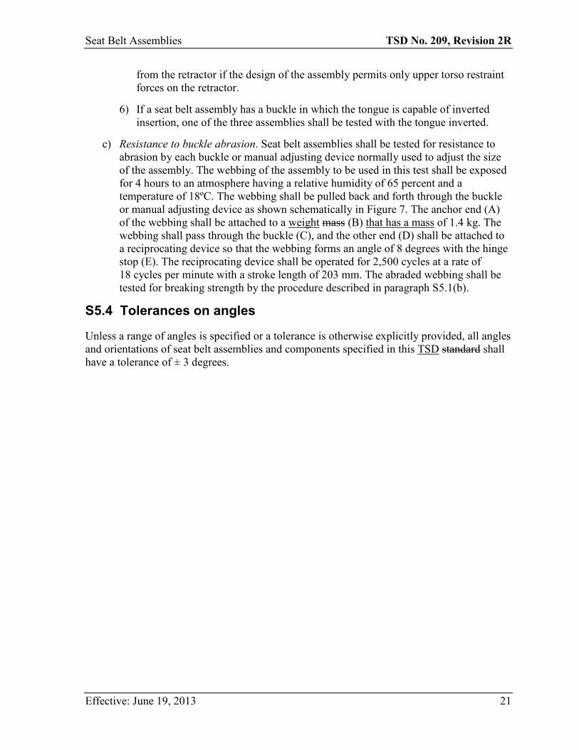
b) Breaking strength. Webbing from three seat belt assemblies shall be conditioned in accordance with paragraph (a) of this section and tested for breaking strength in a testing machine of a capacity verified to have an error of not more than one percent in the range of the breaking strength of the webbing in accordance with ASTM E4-79 (incorporated by reference, see the list at Chapter V, Title 49, part § 571.5 paragraph (d), of the Code of Federal Regulations).16 The machine shall be equipped with split drum grips illustrated in Figure 1, having a diameter between 51 and 102 mm. The rate of grip separation shall be between 51 and 102 mm per minute. The distance between the centers of the grips at the start of the test shall be between 102 and 254 mm. After placing the specimen in the grips, the webbing shall be stretched continuously at a uniform rate to failure. Each value shall be not less than the applicable breaking strength requirement in S4.2(b), but the median value shall be
12 Please see subsection 209(12) of the MVSR for an additional requirement. 13 Please see subsection 209(9) of the MVSR for a related provision. 14 Please see subsection 209(9) of the MVSR for a related provision. 15 Please see subsections 209(4) and (6) of the MVSR for additional requirements. 16 Please see subsection 209(7) of the MVSR for an alternative requirement.
Effective: June 19, 2013 10
Seat Belt Assemblies TSD No. 209, Revision 2R
used for determining the retention of breaking strength in paragraphs (d), (e), and (f) of this section.
c) Elongation. Elongation shall be measured during the breaking strength test described in paragraph (b) of this section by the following procedure: A preload between 196 N and 245 N shall be placed on the webbing mounted in the grips of the testing machine and the needle points of an extensometer, in which the points remain parallel during the test, are inserted in the center of the specimen. Initially the points shall be set at a known distance apart between 102 and 203 mm. When the force on the webbing reaches the value specified in S4.2(c), the increase in separation of the points of the extensometer shall be measured and the percent elongation shall be calculated to the nearest 0.5 percent. Each value shall be not more than the appropriate elongation requirement in S4.2(c).
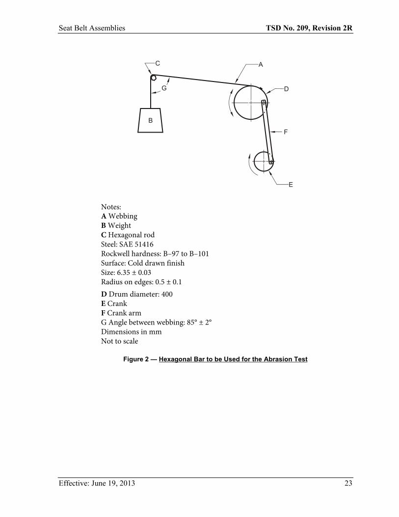
d) Resistance to abrasion. The webbing from three seat belt assemblies shall be tested for resistance to abrasion by rubbing over the hexagon bar prescribed in Figure 2 in the following manner: The webbing shall be mounted in the apparatus shown schematically in Figure 2. One end of the webbing (A) shall be attached to a weight mass (B) that has a mass of 2.35 ± 0.05 kg, except that a weight that has a mass of 1.5 ± 0.05 kg shall be used for webbing in pelvic and upper torso restraints of a belt assembly used in a child restraint system. The webbing shall be passed over the two new abrading edges of the hexagon bar (C) and the other end attached to an oscillating drum (D) which has a stroke of 330 mm. Suitable guides shall be used to prevent movement of the webbing along the axis of hexagonal bar C. Drum D shall be oscillated for 5,000 strokes or 2,500 cycles at a rate of 60 ± 2 strokes per minute or 30 ± 1 cycles per minute. The abraded webbing shall be conditioned as prescribed in paragraph (a) of this section and tested for breaking strength by the procedure described in paragraph (b) of this section. The median values for the breaking strengths determined on abraded and unabraded specimens shall be used to calculate the percentage of breaking strength retained.
e) Resistance to light. Webbing at least 508 mm in length from three seat belt assemblies shall be suspended vertically on the inside of the specimen rack in a Type E carbon-arc light exposure apparatus described in ASTM G23-81 (incorporated by reference, see the list at Chapter V, Title 49, part § 571.5 paragraph (d), of the Code of Federal Regulations),17 except that the filter used for 100 percent polyester yarns shall be chemically strengthened soda-lime glass with a transmittance of less than 5 percent for wave lengths equal to or less than 305 nanometers and 90 percent or greater transmittance for wave lengths of 375 to 800 nanometers. The apparatus shall be operated without water spray at an air temperature of 60 ± 2ºC measured at a point 25 ± 5 mm outside the specimen rack and midway in height. The temperature sensing element shall be shielded from radiation. The specimens shall be exposed to light from the carbon-arc for 100 hours and then conditioned as prescribed
17 Please see subsection 209(7) of the MVSR for an alternative requirement.
Effective: June 19, 2013 11
Seat Belt Assemblies TSD No. 209, Revision 2R
in paragraph (a) of this section. The colorfastness of the exposed and conditioned specimens shall be determined on the AATCC Gray Scale for Evaluating Change in Color (incorporated by reference, see the list at Chapter V, Title 49, part § 571.5 paragraph (b), of the Code of Federal Regulations). The breaking strength of the specimens shall be determined by the procedure prescribed in paragraph (b) of this section. The median values for the breaking strengths determined on exposed and unexposed specimens shall be used to calculate the percentage of breaking strength retained.
f) Resistance to micro-organisms. Webbing at least 508 milimeters (mm) in length from three seat belt assemblies shall first be preconditioned in accordance with Appendix A(1) and (2) of AATCC Test Method 30-1981(incorporated by reference, see the list at Chapter V, Title 49, part § 571.5 paragraph (b), of the Code of Federal Regulations) , and then subjected to Test I, “Soil Burial” of that test method.18 After soil-burial for a period of 2 weeks, the specimen shall be washed in water, dried, and conditioned as prescribed in paragraph (a) of this section. The breaking strengths of the specimens shall be determined by the procedure prescribed in paragraph (b) of this section. The median values for the breaking strengths determined on exposed and unexposed specimens shall be used to calculate the percentage of breaking strength retained.
Note: This test shall not be required on webbing made from material which is inherently resistant to micro-organisms.
S5.2 Hardware
a) Corrosion resistance. Three seat belt assemblies shall be tested in accordance with ASTM B 117-73 (Reapproved 1979) (incorporated by reference, see the list at Chapter V, Title 49, part § 571.5 paragraph (d), of the Code of Federal Regulations).19 Any surface coating or material not intended for permanent retention on the metal parts during service life shall be removed prior to preparation of the test specimens for testing. The period of the test shall be 50 hours for all attachment hardware at or near the floor, consisting of two periods of 24 hours of exposure to salt spray followed by 1 hour of drying, and 25 hours for all other hardware, consisting of one period of 24 hours of exposure to salt spray followed by 1 hour of drying. In the salt spray test chamber, the parts from the three assemblies shall be oriented differently, selecting those orientations most likely to develop corrosion on the larger areas. At the end of test, the seat belt assembly shall be washed thoroughly with water to remove the salt. After drying for at least 24 hours under the standard laboratory conditions specified in S5.1(a), attachment hardware shall be examined for ferrous corrosion on significant surfaces, that is, all surfaces that can be contacted by a sphere
18 Please see subsection 209(7) of the MVSR for an alternative requirement. 19 Please see subsection 209(7) of the MVSR for an alternative requirement.
Effective: June 19, 2013 12
Seat Belt Assemblies TSD No. 209, Revision 2R
19 mm in diameter, and other hardware shall be examined for ferrous and nonferrous corrosion which may be transferred, either directly or by means of the webbing, to a person or his clothing during use of a seat belt assembly incorporating the hardware.
Note: When attachment and other hardware are permanently fastened, by sewing or other means, to the same piece of webbing, separate assemblies shall be used to test the two types of hardware. The test for corrosion resistance shall not be required for attachment hardware made from corrosion-resistant steel containing at least 11.5 percent chromium or for attachment hardware protected with an electrodeposited coating of nickel, or copper and nickel, as prescribed in S4.3(a). The assembly that has been used to test the corrosion resistance of the buckle shall be used to measure adjustment force, tilt-lock adjustment, and buckle latch in paragraphs (e), (f), and (g), respectively, of this section, assembly performance in S5.3, and buckle release force in paragraph (d) of this section.
b) Temperature resistance. Three seat belt assemblies having plastic or nonmetallic hardware or having retractors shall be subjected to the conditions prescribed in Procedure D of ASTM D756-78 (incorporated by reference, see the list at Chapter V, Title 49, part § 571.5 paragraph (d), of the Code of Federal Regulations).20 The dimension and weight measurement shall be omitted. Buckles shall be unlatched and retractors shall be fully retracted during conditioning. The hardware parts, after conditioning, shall be used for all applicable tests in S4.3 and S4.4.
c) Attachment hardware
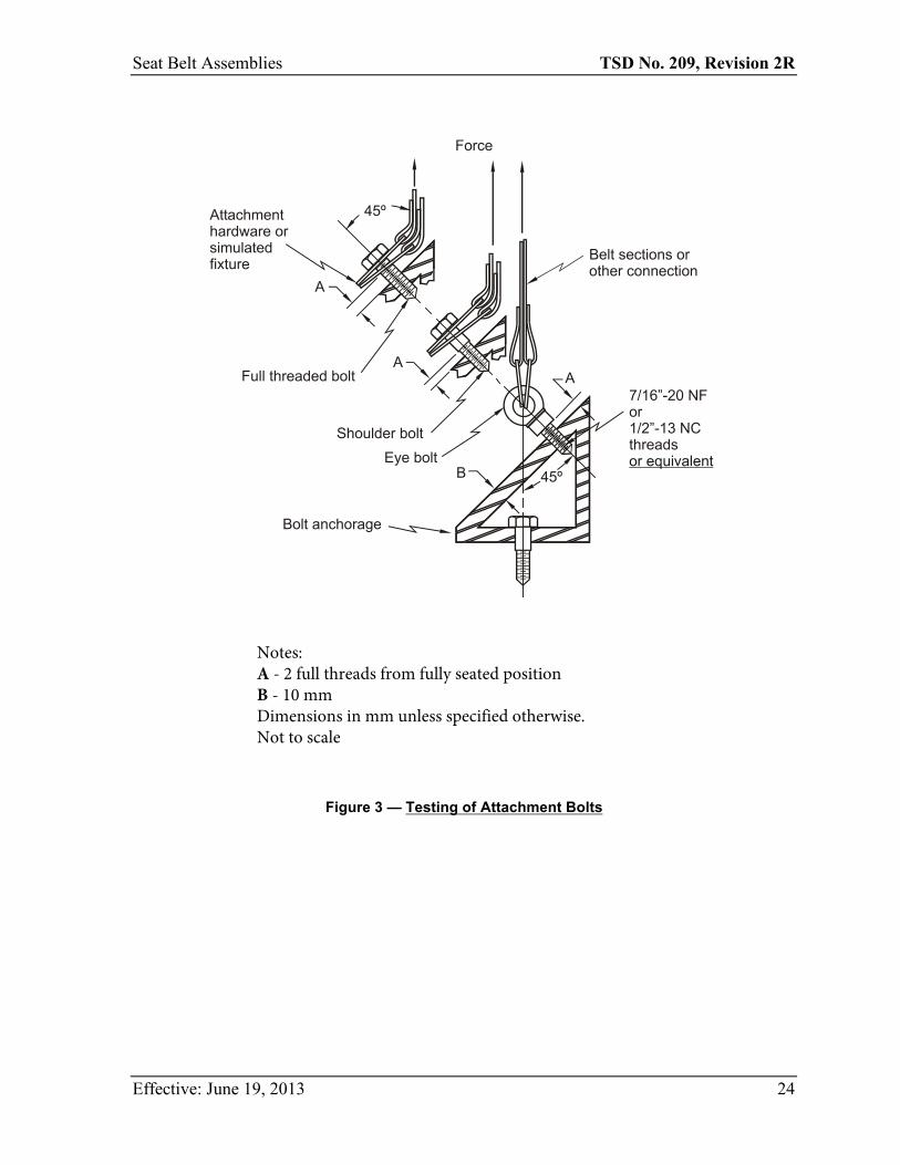
1) Attachment bolts used to secure the pelvic restraint of a seat belt assembly to a motor vehicle shall be tested in a manner similar to that shown in Figure 3. The load shall be applied at an angle of 45 degrees to the axis of the bolt through attachment hardware from the seat belt assembly, or through a special fixture which simulates the loading applied by the attachment hardware. The attachment hardware or simulated fixture shall be fastened by the bolt to the anchorage shown in Figure 3, which has a standard 7/16-20 UNF-2B or ½-13 UNC-2B or metric equivalent threaded hole in a hardened steel plate at least 10 mm in thickness. The bolt shall be installed with two full threads exposed from the fully seated position. The appropriate force required by S4.3(c) shall be applied. A bolt from each of three seat belt assemblies shall be tested.
2) Attachment hardware, other than bolts, designed to receive the ends of two seat belt assemblies shall be subjected to a tensile force of 26,689 N in a manner simulating use. The hardware shall be examined for fracture after the force is released. Attachment hardware from three seat belt assemblies shall be tested.
3) Single attachment hooks for connecting webbing to any eye bolt shall be tested in the following manner: The hook shall be held rigidly so that the retainer latch or
20 Please see subsection 209(7) of the MVSR for an alternative requirement.
Effective: June 19, 2013 13
Seat Belt Assemblies TSD No. 209, Revision 2R
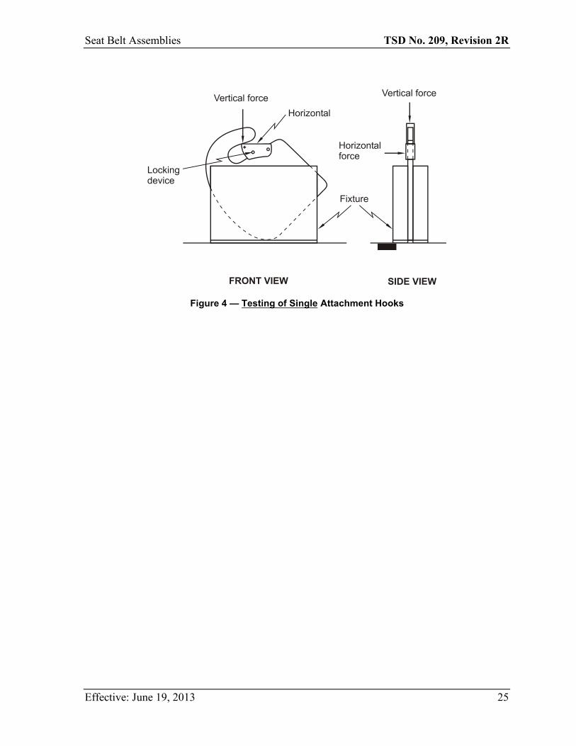
keeper, with cotter pin or other locking device in place, is in a horizontal position as shown in Figure 4. A force of 667 ± 9 N shall be applied vertically as near as possible to the free end of the retainer latch, and the movement of the latch by this force at the point of application shall be measured. The vertical force shall be released, and a force of 667 ± 9 N shall be applied horizontally as near as possible to the free end of the retainer latch. The movement of the latch by this force at the point of load application shall be measured. Alternatively, the hook may be held in other positions, provided the forces are applied and the movements of the latch are measured at the points indicated in Figure 4. A single attachment hook from each of three seat belt assemblies shall be tested.
d) Buckle release
1) Three seat belt assemblies shall be tested to determine compliance with the maximum buckle release force requirements, following the assembly test in S5.3. After subjection to the force applicable for the assembly being tested, the force shall be reduced and maintained at 667 N on the assembly loop of a Type 1 seat belt assembly, 334 N on the components of a Type 2 seat belt assembly. The buckle release force shall be measured by applying a force on the buckle in a manner and direction typical of those which would be employed by a seat belt occupant. For push-button-release buckles, the force shall be applied on the centerline at least 3 mm from the edge of the push-button access opening of the buckle in a direction that produces maximum releasing effect. For lever-release buckles, the force shall be applied at least 3 mm from the edge on the centerline of the buckle lever or finger tab in a direction that produces maximum releasing effect.
2) The area for application of release force on a push-button-actuated buckle shall be measured to the nearest 30 mm2. The cylinder specified in S4.3(d) shall be inserted in the actuation portion of a lever-released buckle for determination of compliance with the requirement. A buckle with other release actuation shall be examined for access of release by fingers.
3) The buckle of a Type 1 or Type 2 seat belt assembly shall be subjected to a compressive force of 1,779 N applied anywhere on a test line that is coincident with the centerline of the belt extended through the buckle or on any line that extends over the center of the release mechanism and intersects the extended centerline of the belt at an angle of 60 degrees. The load shall be applied by using a curved cylindrical bar having a cross section diameter of 19 mm and a radius of curvature of 152 mm, placed with its longitudinal centerline along the test line and its center directly above the point or the buckle to which the load will be applied. The buckle shall be latched, and a tensile force of 334 N shall be applied to the connected webbing during the application of the compressive force. Buckles from three seat belt assemblies shall be tested to determine compliance with paragraph S4.3(d)(3).
e) Adjustment Force. Three seat belt assemblies shall be tested for adjustment force on the webbing at the buckle or other manual adjusting device normally used to adjust the size of the assembly. With no load on the anchor end, the webbing shall be drawn through the adjusting device at a rate of 508 ± 50 mm per minute and the maximum
Effective: June 19, 2013 14
Seat Belt Assemblies TSD No. 209, Revision 2R
force shall be measured to the nearest 1 N after the first 25 mm of webbing movement. The webbing shall be precycled 10 times prior to measurement.
f) Tilt-lock adjustment. This test shall be made on buckles or other manual adjusting devices having a tilt-lock adjustment normally used to adjust the size of the assembly. Three buckles or devices shall be tested. The base of the adjustment mechanism and the anchor end of the webbing shall be oriented in planes normal to each other. The webbing shall be drawn through the adjustment mechanism in a direction to increase belt length at a rate of 508 ± 50 mm per minute while the plane of the base is slowly rotated in a direction to lock the webbing. Rotation shall be stopped when the webbing locks, but the pull on the webbing shall be continued until there is a resistance of at least 89 N. The locking angle between the anchor end of the webbing and the base of the adjustment mechanism shall be measured to the nearest degree. The webbing shall be precycled 10 times prior to measurement.
g) Buckle latch. The buckles from three seat belt assemblies shall be opened fully and closed at least 10 times. Then the buckles shall be clamped or firmly held against a flat surface so as to permit normal movement of the buckle parts, but with the metal mating plate (metal-to-metal buckles) or webbing end (metal-to-webbing buckles) withdrawn from the buckle. The release mechanism shall be moved 200 times through the maximum possible travel against its stop with a force of 133 ± 13 N at a rate not to exceed 30 cycles per minute. The buckle shall be examined to determine compliance with the performance requirements of S4.3(g). A metal-to-metal buckle shall be examined to determine whether partial engagement is possible by means of any technique representative of actual use. If partial engagement is possible, the maximum force of separation when in such partial engagement shall be determined.
h) Nonlocking retractor. [CONTENT DELETED]21
i) Automatic-locking retractor. Three retractors shall be tested in a manner to permit the retraction force to be determined exclusive of the gravitational forces on the hardware or webbing being retracted. The webbing shall be fully extended from the retractor. While the webbing is being retracted, the average force of retraction within plus or minus 51 mm of 75 percent extension (25 percent retraction) shall be determined and the webbing movement between adjacent locking segments shall be measured in the same region of extension. A seat belt assembly with an automatic-locking retractor in an upper torso restraint shall be tested in a vehicle in a manner prescribed by the installation and usage instructions. The retraction force on the occupant of the seat belt assembly shall be determined before and after traveling for 10 minutes at a speed of 24 kilometers per hour or more over a rough road (e.g., Belgian block road) where the occupant is subjected to displacement with respect to the vehicle in both horizontal and vertical directions. Measurements shall be made with the vehicle stopped and the occupant in the normal seated position.
21 Please see subsection 209(11) of the MVSR for a related provision.
Effective: June 19, 2013 15
Seat Belt Assemblies TSD No. 209, Revision 2R
j) Emergency-locking retractor
1) For seat belt assemblies manufactured before February 22, 2007. Except for manufacturers that elect to comply with S4.3(j)(2) and the corresponding test procedures of S5.2(j)(2), a retractor shall be tested in a manner that permits the retraction force to be determined exclusive of the gravitational forces on the hardware or webbing being retracted. The webbing shall be fully extended from the retractor, passing over or through any hardware or other material specified in the installation instructions. While the webbing is being retracted, the lowest force of retraction within ± 51 mm of 75 percent extension shall be determined. A retractor that is sensitive to webbing withdrawal shall be subjected to an acceleration of 3 m/s2 (0.3 g) within a period of 50 milliseconds (ms), while the webbing is at 75 percent extension, to determine compliance with S4.3(j)(1)(ii). The retractor shall be subjected to an acceleration of 7 m/s2 (0.7 g) within a period of 50 ms, while the webbing is at 75 percent extension, and the webbing movement before locking shall be measured under the following conditions: For a retractor sensitive to webbing withdrawal, the retractor shall be accelerated in the direction of webbing retraction while the retractor drum’s central axis is oriented horizontally and at angles of 45, 90, 135, and 180 degrees to the horizontal plane. For a retractor sensitive to vehicle acceleration, the retractor shall be:
i. Accelerated in the horizontal plane in two directions normal to each other, while the retractor drum’s central axis is oriented at the angle at which it is installed in the vehicle; and
ii. Accelerated in three directions normal to each other, while the retractor drum’s central axis is oriented at angles of 45, 90, 135, and 180 degrees from the angle at which it is installed in the vehicle, unless the retractor locks by gravitational force when tilted in any direction to any angle greater than 45 degrees from the angle at which it is installed in the vehicle.
2) For seat belt assemblies manufactured on or after February 22, 2007, and for manufacturers opting for early compliance. A retractor shall be tested in a manner that permits the retraction force to be determined exclusive of the gravitational forces on the hardware or webbing being retracted.
i. Retraction force: The webbing shall be extended fully from the retractor, passing over and through any hardware or other material specified in the installation instructions. While the webbing is being retracted, measure the lowest force of retraction within ± 51 mm of 75 percent extension.
ii. Gravitational locking: For a retractor sensitive to vehicle acceleration, rotate the retractor in any direction to an angle greater than 45 degrees from the angle at which it is installed in the vehicle. Apply a force to the webbing greater than the minimum force measured in S5.2(j)(2)(i) to determine compliance with S4.3(j)(2)(i)(D).
iii. Dynamic tests: Each acceleration pulse shall be recorded using an accelerometer having a full-scale range of ± 10 g and processed according to the practices set
Effective: June 19, 2013 16
Seat Belt Assemblies TSD No. 209, Revision 2R
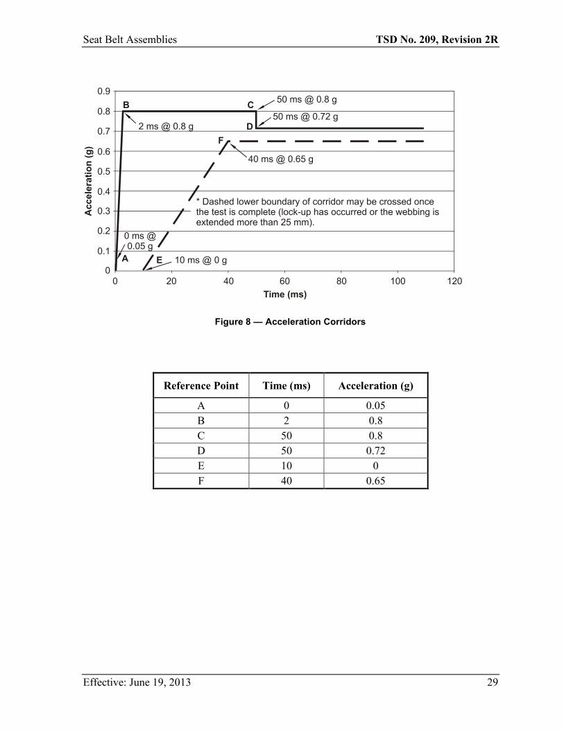
forth in SAE Recommended Practice J211-1 DEC 2003 (incorporated by reference, see the list at Chapter V, Title 49, part § 571.5 paragraph (k), of the Code of Federal Regulations), Channel Frequency Class 60. The webbing shall be positioned at 75 percent extension, and the displacement shall be measured using a displacement transducer. For tests specified in S5.2(j)(2)(iii)(A) and (B), the 0.7 g acceleration pulse shall be within the acceleration-time corridor shown in Figure 8 of this TSD standard.
A. For a retractor sensitive to vehicle acceleration,
1. The retractor drum’s central axis shall be oriented at the angle at which it is installed in the vehicle ± 0.5 degree. Accelerate the retractor in the horizontal plane in two directions normal to each other and measure the webbing payout; and
2. If the retractor does not meet the 45-degree tilt-lock requirement of S4.3(j)(2)(i)(D), accelerate the retractor in three directions normal to each other while the retractor drum’s central axis is oriented at angles of 45, 90, 135, and 180 degrees from the angle at which it is installed in the vehicle and measure webbing payout.
B. For a retractor sensitive to webbing withdrawal,
1. The retractor drum’s central axis shall be oriented horizontally ± 0.5 degree. Accelerate the retractor in the direction of webbing retraction and measure webbing payout; and
2. The retractor drum’s central axis shall be oriented at angles of 45, 90, 135, and 180 degrees to the horizontal plane. Accelerate the retractor in the direction of the webbing retraction and measure the webbing payout.
C. A retractor that is sensitive to webbing withdrawal shall be subjected to an acceleration no greater than 0.3 g occurring within a period of the first 50 ms and sustaining an acceleration no greater than 0.3 g throughout the test, while the webbing is at 75 percent extension. Measure the webbing payout.
k) Performance of retractor. After completion of the corrosion-resistance test described in paragraph (a) of this section, the webbing shall be fully extended and allowed to dry for at least 24 hours under the standard laboratory conditions specified in S5.1(a). The retractor shall be examined for ferrous and nonferrous corrosion which may be transferred, either directly or by means of the webbing, to a person or his clothing during use of a seat belt assembly incorporating the retractor, and for ferrous corrosion on significant surfaces if the retractor is part of the attachment hardware. The webbing shall be withdrawn manually and allowed to retract for 25 cycles. The retractor shall be mounted in an apparatus capable of extending the webbing fully, applying a force of 89 N at full extension, and allowing the webbing to retract freely and completely. The webbing shall be withdrawn from the retractor and allowed to retract repeatedly in this apparatus until 2,500 cycles are completed. The retractor and webbing shall then be subjected to the temperature resistance test prescribed in
Effective: June 19, 2013 17
Seat Belt Assemblies TSD No. 209, Revision 2R
paragraph (b) of this section. The retractor shall be subjected to 2,500 additional cycles of webbing withdrawal and retraction.
Then, the retractor and webbing shall be subjected to dust in a chamber similar to the one illustrated in Figure 6 8 containing about 0.9 kg of coarse grade dust conforming to the specification given in SAE Recommended Practice J726 SEP79 (incorporated by reference, see the list at Chapter V, Title 49, part § 571.5 paragraph (k), of the Code of Federal Regulations). The dust shall be agitated every 20 minutes for 5 seconds by compressed air, free of oil and moisture, at a gage pressure of 550 ± 55 kPa entering through an orifice 1.5 ± 0.1 mm in diameter. The webbing shall be extended to the top of the chamber and kept extended at all times, except that the webbing shall be subjected to 10 cycles of complete retraction and extension within 1 to 2 minutes after each agitation of the dust. At the end of 5 hours, the assembly shall be removed from the chamber. The webbing shall be fully withdrawn from the retractor manually and allowed to retract completely for 25 cycles. An automatic-locking retractor or a nonlocking retractor22 attached to a pelvic restraint shall be subjected to 5,000 additional cycles of webbing withdrawal and retraction. An emergency-locking retractor or a nonlocking retractor attached to an upper torso restraint shall be subjected to 45,000 additional cycles of webbing withdrawal and retraction between 50 and 100 percent extension. The locking mechanism of an emergency-locking retractor shall be actuated at least 10,000 times within 50 to 100 percent extension of webbing during the 50,000 cycles. At the end of the test, compliance of the retractors with applicable requirements in S4.3(h), (i), and (j) shall be determined. Three retractors shall be tested for performance.
S5.3 Assembly performance
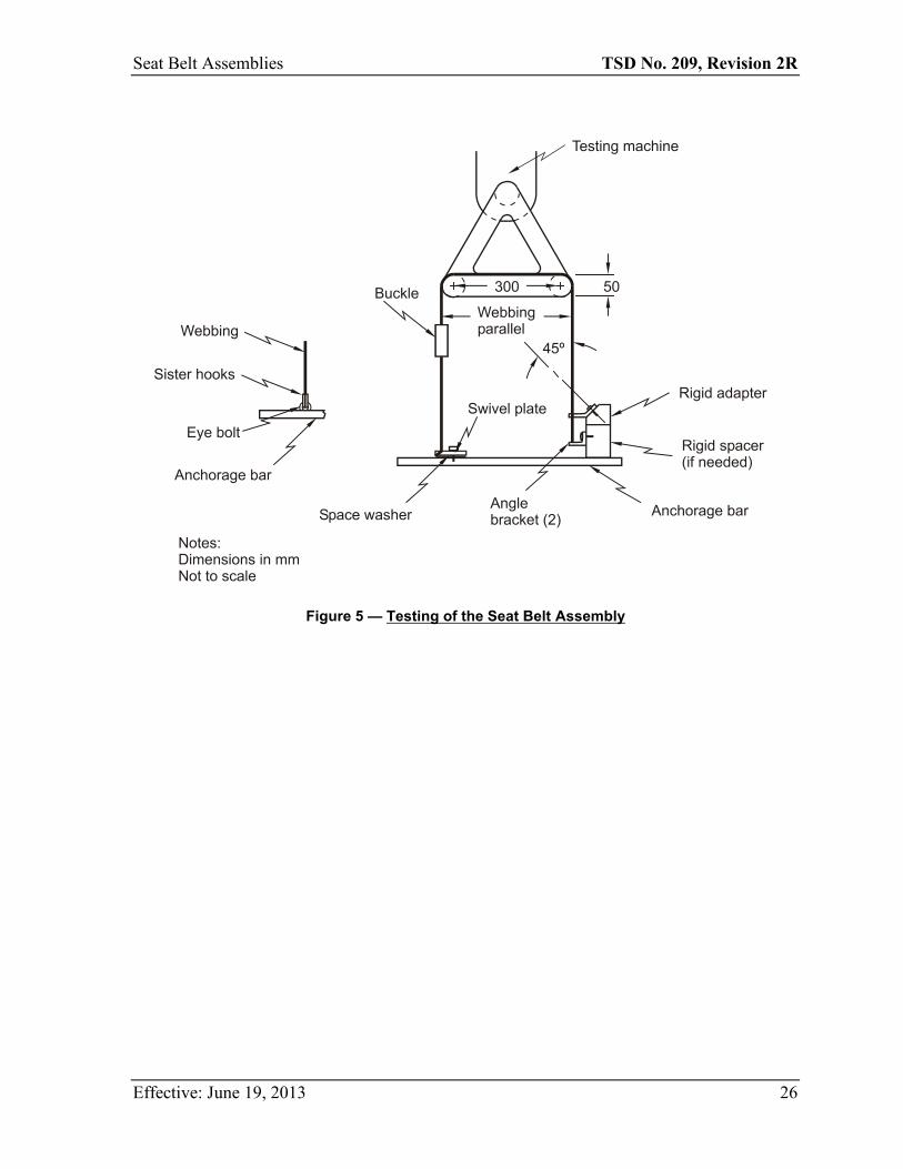
a) Type 1 seat belt assembly. Three complete seat belt assemblies, including webbing, straps, buckles, adjustment and attachment hardware, and retractors, arranged in the form of a loop as shown in Figure 5, shall be tested in the following manner:
1) The testing machine shall conform to the requirements specified in S5.1(b). A double-roller block shall be attached to one head of the testing machine. This block shall consist of two rollers 102 mm in diameter and sufficiently long so that no part of the seat belt assembly touches parts of the block other than the rollers during test. The rollers shall be mounted on antifriction bearings and spaced 305 mm between centers, and shall have sufficient capacity so that there is no brinelling, bending, or other distortion of parts which may affect the results. An anchorage bar shall be fastened to the other head of the testing machine.
2) The attachment hardware furnished with the seat belt assembly shall be attached to the anchorage bar. The anchor points shall be spaced so that the webbing is parallel in the two sides of the loop. The attaching bolts shall be parallel to, or at
22 Please see subsection 209(11) of the MVSR for a related provision.
Effective: June 19, 2013 18
Seat Belt Assemblies TSD No. 209, Revision 2R
an angle of 45 or 90 degrees to, the webbing, whichever results in an angle nearest to 90 degrees between the webbing and the attachment hardware, except that eye bolts shall be vertical, and the attaching bolts or nonthreaded anchorages of a seat belt assembly designed for use in specific models of motor vehicles shall be installed to produce the maximum angle in use indicated by the installation instructions, utilizing special fixtures if necessary to simulate installation in the motor vehicle. Rigid adapters between the anchorage bar and attachment hardware shall be used if necessary to locate and orient the adjustment hardware. The adapters shall have a flat support face perpendicular to the threaded hole for the attaching bolt and adequate in area to provide full support for the base of the attachment hardware connected to the webbing. If necessary, a washer shall be used under a swivel plate or other attachment hardware to prevent the webbing from being damaged as the attaching bolt is tightened.
3) The length of the assembly loop from attaching bolt to attaching bolt shall be adjusted to about 1,295 mm, or as near thereto as possible. A force of 245 N shall be applied to the loop to remove any slack in the webbing at the hardware. The force shall be removed and the heads of the testing machine shall be adjusted for an assembly loop between 1,220 and 1,270 mm in length. The length of the assembly loop shall then be adjusted by applying a force between 89 and 98 N to the free end of the webbing at the buckle, or by the retraction force of an automatic-locking or emergency-locking retractor. A seat belt assembly that cannot be adjusted to this length shall be adjusted as closely as possible. An automatic-locking or emergency-locking retractor, when included in a seat belt assembly, shall be locked at the start of the test with a tension on the webbing slightly in excess of the retractive force in order to keep the retractor locked. The buckle shall be in a location so that it does not touch the rollers during the test, but to facilitate making the buckle release test in S5.2(d), the buckle should be between the rollers or near a roller in one leg.
4) The heads of the testing machine shall be separated at a rate between 51 and 102 mm per minute until a force of 22,241 ± 222 N is applied to the assembly loop. The extension of the loop shall be determined from measurements of head separation before and after the force is applied. The force shall be decreased to 667 ± 45 N and the buckle release force measured as prescribed in S5.2(d).
5) After the buckle is released, the webbing shall be examined for cutting by the hardware. If the yarns are partially or completely severed in a line for a distance of 10 percent or more of the webbing width, the cut webbing shall be tested for breaking strength as specified in S5.1(b), locating the cut in the free length between grips. If there is insufficient webbing on either side of the cut to make such a test for breaking strength, another seat belt assembly shall be used with the webbing repositioned in the hardware. A tensile force of 11,120 ± 111 N shall be applied to the components or a force of 22,241 ± 222 N shall be applied to the assembly loop. After the force is removed, the breaking strength of the cut webbing shall be determined as prescribed above.
Effective: June 19, 2013 19
Seat Belt Assemblies TSD No. 209, Revision 2R
6) If a Type 1 seat belt assembly includes an automatic-locking retractor or an emergency-locking retractor, the webbing and retractor shall be subjected to a tensile force of 11,120 ± 111 N with the webbing fully extended from the retractor.
7) If a seat belt assembly has a buckle in which the tongue is capable of inverted insertion, one of the three assemblies shall be tested with the tongue inverted.
b) Type 2 seat belt assembly. Components of three seat belt assemblies shall be tested in the following manner:
1) The pelvic restraint between anchorages shall be adjusted to a length between 1,220 and 1,270 mm, or as near this length as possible if the design of the pelvic restraint does not permit its adjustment to this length. An automatic-locking or emergency-locking retractor, when included in a seat belt assembly, shall be locked at the start of the test with a tension on the webbing slightly in excess of the retractive force in order to keep the retractor locked. The attachment hardware shall be oriented to the webbing as specified in paragraph (a)(2) of this section and illustrated in Figure 5. A tensile force of 11,120 ± 111 N shall be applied on the components in any convenient manner and the extension between anchorages under this force shall be measured. The force shall be reduced to 334 ± 22 N and the buckle release force measured as prescribed in S5.2(d).
2) The components of the upper torso restraint shall be subjected to a tensile force of 6,672 ± 67 N following the procedure prescribed above for testing the pelvic restraint, and the extension between anchorages under this force shall be measured. If the testing apparatus permits, the pelvic and upper torso restraints may be tested simultaneously. The force shall be reduced to 334 ± 22 N and the buckle release force measured as prescribed in S5.2(d).
3) Any component of the seat belt assembly common to both the pelvic and upper torso restraint shall be subjected to a tensile force of 13,344 ± 134 N.
4) After the buckle is released in the tests of the pelvic and upper torso restraints, the webbing shall be examined for cutting by the hardware. If the yarns are partially or completely severed in a line for a distance of 10 percent or more of the webbing width, the cut webbing shall be tested for breaking strength as specified in S5.1(b), locating the cut in the free length between grips. If there is insufficient webbing on either side of the cut to make such a test for breaking strength, another seat belt assembly shall be used with the webbing repositioned in the hardware. The force applied shall be 11,120 ± 111 N for the components of a pelvic restraint and 6,672 ± 67 N for the components of an upper torso restraint. After the force is removed, the breaking strength of the cut webbing shall be determined as prescribed above.
5) If a Type 2 seat belt assembly includes an automatic-locking retractor or an emergency-locking retractor, the webbing and retractor shall be subjected to a tensile force of 11,120 ± 111 N with the webbing fully extended from the retractor, or to a tensile force of 6,672 ± 67 N with the webbing fully extended
Effective: June 19, 2013 20
Seat Belt Assemblies TSD No. 209, Revision 2R
from the retractor if the design of the assembly permits only upper torso restraint forces on the retractor.
6) If a seat belt assembly has a buckle in which the tongue is capable of inverted insertion, one of the three assemblies shall be tested with the tongue inverted.
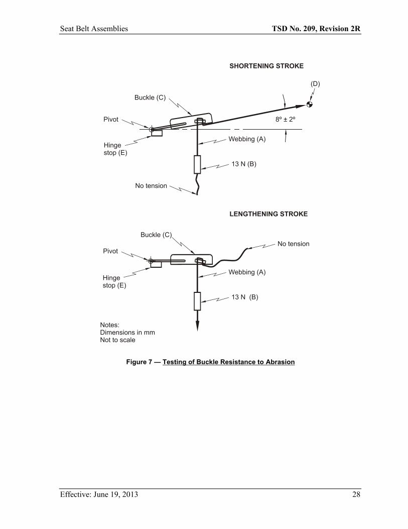
c) Resistance to buckle abrasion. Seat belt assemblies shall be tested for resistance to abrasion by each buckle or manual adjusting device normally used to adjust the size of the assembly. The webbing of the assembly to be used in this test shall be exposed for 4 hours to an atmosphere having a relative humidity of 65 percent and a temperature of 18ºC. The webbing shall be pulled back and forth through the buckle or manual adjusting device as shown schematically in Figure 7. The anchor end (A) of the webbing shall be attached to a weight mass (B) that has a mass of 1.4 kg. The webbing shall pass through the buckle (C), and the other end (D) shall be attached to a reciprocating device so that the webbing forms an angle of 8 degrees with the hinge stop (E). The reciprocating device shall be operated for 2,500 cycles at a rate of 18 cycles per minute with a stroke length of 203 mm. The abraded webbing shall be tested for breaking strength by the procedure described in paragraph S5.1(b).
S5.4 Tolerances on angles
Unless a range of angles is specified or a tolerance is otherwise explicitly provided, all angles and orientations of seat belt assemblies and components specified in this TSD standard shall have a tolerance of ± 3 degrees.
Effective: June 19, 2013 21
Seat Belt Assemblies TSD No. 209, Revision 2R
Figure 1 — Split Drum Grips to be Used for the Webbing Strength Tests
Effective: June 19, 2013 22
Seat Belt Assemblies TSD No. 209, Revision 2R
Figure 2 — Hexagonal Bar to be Used for the Abrasion Test
Effective: June 19, 2013 23
Notes:A WebbingB WeightC Hexagonal rodSteel: SAE 51416Rockwell hardness: B–97 to B–101Surface: Cold drawn finishSize: 6.35 ± 0.03Radius on edges: 0.5 ± 0.1D Drum diameter: 400E CrankF Crank armG Angle between webbing: 85° ± 2°Dimensions in mmNot to scale
Seat Belt Assemblies TSD No. 209, Revision 2R
Figure 3 — Testing of Attachment Bolts
Effective: June 19, 2013 24
Notes:A - 2 full threads from fully seated positionB - 10 mmDimensions in mm unless specified otherwise.Not to scale
Seat Belt Assemblies TSD No. 209, Revision 2R
Figure 4 — Testing of Single Attachment Hooks
Effective: June 19, 2013 25
Seat Belt Assemblies TSD No. 209, Revision 2R
Figure 5 — Testing of the Seat Belt Assembly
Effective: June 19, 2013 26

Seat Belt Assemblies TSD No. 209, Revision 2R
Figure 6 — Dust Chamber for Retractor Cycling
Effective: June 19, 2013 27
Seat Belt Assemblies TSD No. 209, Revision 2R
Figure 7 — Testing of Buckle Resistance to Abrasion
Effective: June 19, 2013 28
Seat Belt Assemblies TSD No. 209, Revision 2R
Figure 8 — Acceleration Corridors
Reference Point Time (ms) Acceleration (g)
A 0 0.05 B 2 0.8 C 50 0.8 D 50 0.72 E 10 0 F 40 0.65
Effective: June 19, 2013 29


![Nighttime Seat Belt Enforcement Strategies1].pdf · 2009-05-15 · Nighttime Seat Belt Enforcement Strategies Background: Seat belt use rates have reached relatively high levels in](https://static.fdocuments.net/doc/165x107/5f144ff982cd99492d258993/nighttime-seat-belt-enforcement-strategies-1pdf-2009-05-15-nighttime-seat.jpg)