
[Sears · Read the Safety Guidelines Before Operating AIR ... 20 amp 20 amp 20 amp. min. 15 amp...
16
[Sears OWNERS MANUAL MODEL NOS. 919.174211 919.174310 919.174320 919.174410 IMPORTANT: Read the Safety Guidelines Before Operating AIR COMPRESSOR DESCRIPTION ASSEMBLY OPERATION MAINTENANCE REPAIR PARTS Record in the spaces provided below the model number, code number and manufacturers num- ber of this air compressor. The model number can be found on the label on the front of the air tank. The code number can be found on the foil label on the rear of the air tank. The manufacturers number (ASME Code outfits only) is located on the metal data plate on the right front of the saddle. Model No. Code No. Mfgs. No. Motor Mfgo Name Motor Mfg. No. Retain these numbers for future refeFences. Sears, Roebuck and Co, Chicago, _L 60684 U.S.Ao St-30+14-_ 2/83
Transcript of [Sears · Read the Safety Guidelines Before Operating AIR ... 20 amp 20 amp 20 amp. min. 15 amp...

[SearsOWNERSMANUAL
MODEL NOS.919.174211919.174310919.174320919.174410
IMPORTANT:Read the SafetyGuidelines BeforeOperating
AIR
COMPRESSOR
DESCRIPTIONASSEMBLY
OPERATIONMAINTENANCEREPAIR PARTS
Record in the spaces providedbelow the model number, codenumber and manufacturers num-
ber of this air compressor. Themodel number can be found onthe label on the front of the airtank. The code number can be
found on the foil label on the rearof the air tank. The manufacturers
number (ASME Code outfits only)is located on the metal data plateon the right front of the saddle.
Model No.
Code No.
Mfgs. No.
Motor Mfgo Name
Motor Mfg. No.
Retain these numbers for future
refeFences.
Sears, Roebuck and Co, Chicago, _L 60684 U.S.AoSt-30+14-_ 2/83

TABLE OF CONTENTS
Page
WARRANTY ....................................................... 3
SAFETY GUIDELINES .............................................. 3
SPECIFICATION CHART ............................................ 5
GENERAL INFORMATION .......................................... 6
GENERAL DESCRIPTION OF OPERATION ........................... 6
ASSEMBLY INSTRUCTIONS ........................................ 6
Tools Needed for Assembly ...................................... 6Attaching Wheels, Handle, Etc .................................... 6Installing Regulator ............................................. 7Start-Up Procedures ............................................ 7
OPERATION ....................................................... 7
Manifold ....................................................... 7Pressure Switch ................................................ 7Safety Valve ................................................... 8Motor ......................................................... 8Pressure Release Valve ......................................... 8
MAINTENANCE .................................................... 8
Replacing Air Intake Filter ....................................... 8Checking Safety Valve .......................................... 8Checking and Changing Oil ...................................... 8Location of Air Compressor ...................................... 9Draining Water From Air Tank .................................... gReplacing Belt .................................................. 9
AIR COMPRESSOR DIAGRAM ...................................... 10
PARTS LIST ....................................................... 11
ACCESSORIES .................................................... 13
TROUBLESHOOTING GUIDE ....................................... 14
HOW TO ORDER REPAIR PARTS ................................... 16

FULL ONE YEAR WARRANTYAIR COMPRESSOR
if this air compressor fails due to a defect in material or workmanship within one year from the date ofpurchase, return it to the nearest Sears store throughout the United States and Sears will repair it,free of charge.
if this air compressor is used for commercial or rental purposes, the warranty will apply for thirty daysfrom date of purchase.
This warranty gives you specific legal rights and you may also have other rights which vary from stateto state.
Sears, Roebuck and Co., Sears Tower, Dept. 698/731A, Chicago, iL 60684
SAFETY GUIDELINES
This manual contains information that is important for you to know and understand•
This information relates to YOUR SAFETY and PREVENTING EQUIPMENT PROBLEMS.
To help you recognize this information we use the following symbols. Please read the manual andpay attention to those sections.
...... Nh_G
;;II-_ORTAa_T _,IFQRMATION FOR PRE-VE'IT',NG ;t._JURY OR LCSS OF L_FE.
information for preventing damage toequipment.
Note
Information that you should pay special atten-tion to.
3

i WARNIN'G I¸L
PLEASE READ THE FOLLOWING CHART.
AREA
indicates where a hazardcan occur.
Moving Parts
HAZARD
indicates what can happen if pre-cautions are not observed.
Loose items, or parts of the bodymay get caught and cause seri-ous injury or damage.
Unit cycles automatically whenpower is ON. During service orrepair activities, this automaticcycling may cause a hazard.
SAFEGUARDS
indicates how to avoid the hazard and what
special protective clothing, equipment, andprecautions will be used.
Never operate the compressor with the beltguard removed.
Keep small children, your hands, and allitems away from the flywheel and belt.
Always unplug the unit before attempting re-pair or maintenance of the compressor. Also,make sure the pressure is released from thecompressor and air tank.
Hot Parts Air compressors get hot when Never touch the compressor, tubing, orrunning. Serious burns may re- motor during or immediately after operationsuit if touched, of the compressor.
Air Tank Air pressure or mechanical loadsthat are higher than design loadsmay cause the tank to rupture.
Changes to the air tank structurewill cause the tank to weaken.Tank rupture or explosion mayoccur.
This unit is powered by 120 or240 volts.
Electrical Shock
Do not adjust, remove, or defeat the safetyvalve. Check the valve from time to time bypulling the ring on the valve. If the valve isstuck or does not operate smoothly, it mustbe replaced.
Do not adjust, remove, or defeat the pres-sure switch.
Never use a motor with higher horsepowerrating than the one supplied.
The compressor was not designed to bepowered by a gasoline engine. Do not substi-tute a gas engine.
Never drill into, weld, or change the tank inany way.
Always unplug unit prior to doing any main-tenance or repair,
Never use the unit outdoors when it is rain-
ing.
Always plug the cord into an electrical outletwith the specified voltage and adequate fuseprotection.
4

AREA
Use of unsuitable solvents
Toxic Vapors
Compressed Air
HAZARD
The solvents l,l,l-Trichlorethaneand Methylene Chloride canchemically react with aluminumused in paint spray guns, paintpumps, etc. and cause an explo-sion. These solvents can alsoreact with galvanized compo-nents and cause corrosion andweakening of parts.
Compressed air from this unitmay contain poisonous carbonmonoxide.
Certain sprayed materials suchas paints, weed kitler, sand,insecticides, etc., may be harmfulif used in a closed area or ifinhaled.
Compressed air may propel dirt,metal shavings, etc. and result inpossible injury.
SAFEGUARDS
This hazard does not affect your compressoroutfit - but it may affect the equipment usedwith the outfit. Read the label or data sheetfor the material you intend to spray. Equip-ment containing aluminum or galvanizedparts that will come in contact with these sol-vents, and that can contain pressure, mustnot be used with these solvents, You musteither change the material, or use onlystainless steel spray equipment.
Never directly inhale the compressed air pro-duced by this unit.
Be certain to read labels when sprayingpaints or poisons.
Use a mask or respirator whenever there is achance that you might inhale anything thatyou are spraying. Read all instructions sothat you know that your mask will protect youfrom what you are spraying.
Never point any nozzle or sprayer toward aperson or any part of the body.
Always wear safety goggles or glasses whenspraying.
SPECIFICATION CHART
Model No.HP
Displacement CFMBoreStroke
Voltage-Single PhaseMinimum Branch Circuit RequirementFuse TypeAmperage at Max. PressureAir Tank CapacityApproximate Cut-in PressureApproximate Cut-out PressureSCFM at 100 psigSCFM at 90 psigSCFM at 40 psig
919.174211 919.174310 919.174410 919.1743201 1 1 2
8.8 8.8 8,8 9.223/4" 23/4" 23/4" 23/4"
2" 2"/_J" 2" 2"110-120 110-220" 110-120 220-240
20 amp 20 amp 20 amp. min. 15 amp min."Fusetron" Type T "Fusetron ° Type T "Fusetron" Type T "Fusetron" Type T
18.2 18.2 18.2 9.912 gal. 12 gaL (ASME) 12 gal. (ASME) 20 gal. (ASME)
80 psig 80 psig 80 psig 80 psig100 psig 100 psig 100 psig 100 psig
5.t 5.1 5.1 5.65.3 5.3 5.3 6.16.6 6.6 6.6 7.5
_SCFM (Standard Cubic Feet per Minute): Unit of measure of air delivery.SLM (Standard Liters per Minute): Metric unit of measure of air delivery.PSIG (Pounds per Square Inch Gauge): Unit of measure of pressure.kPa (Kilo Pascals): Metric unit of measure of pressure.
5

THiS MANUAL iS DESIGNED TO MAKE iT AS EASY AS POSSIBLE
FOR YOU TO SET UP, OPERATE AND MAINTAINYOUR NEW AIR COMPRESSOR
GENERAL INFORMATION ASSEMBLY INSTRUCTIONS
You have purchased a complete portable compressoroutfit consisting of a 2 cylinder single-stage aircompressor with air tank, air hose assembly, wheelsand handle. You will also find an air chuck and ahelpful "Power Painting With Sprayers" booklet. The2 horsepower unit has a removable foot extensionbracket which allows for stationary mounting.
These units can be used for operating caulking guns,grease guns, air brushes, sandblasters, air tools, etc., orinflating tires and plastic toys, spraying weed killer,insecticides, etc.
GENERAL DESCRIPTION OF OPERATION
To compress air, the pistons move up and down in thecylinder. On the downstroke, air is drawn in through theair intake valve. The exhaust valve remains closed. Onthe upstroke of the piston, air is compressed. The intakevalves close and compressed air is forced out throughthe exhaust valve, through the check valve and into theair tank. Working air is not available until the compressorhas raised the air tank pressure above that required atthe air outlet. The air intake opening must be kept clearof obstructions which could reduce air delivery of thecompressor.
Tools Needed For Assembly
Tools needed are: (1) a 9/ld' socket or open end wrenchfor attaching the wheels and hose adapter; and (2) anadjustable wrench for attaching the pressure regulator,and (3) a 7/16"open end wrench for attaching the airpressure gauge, (4) a 7A6"socket or open end wrench forattaching the foot extension bracket (2 hp. unit only), (5)a 3/16"hex key for installing the plug in the regulator and(6) pipe thread sealant.
Attaching Wheels, Handle, Etc.
i .... i
":""-'- V'HEELS A;_D "b':[[CLE 9£ ;'DT_F O_qDE [.DEQU;TE .?.LZ,LR,:.;"CE _T,C-E:LIT"" OR SU_'-'OR_" FOR :J_L! £ "%_,EU!;- LF OR C.OV';,: ST;!RS /.[:: STZ=S.TXE U;4ZTr._US- _E L;-TED ©': PL!_-:EE U_
See diagram on page 10 for attaching air pressureregulator (46), wheels (38), foot extension bracket (43)and handle (47). Refer to the illustration, page 10, KeyNo's. 22, 39, 40, 42, 44, 45, 84, 85 and 86.
AIR INTAKEAND FILTER
ON-AUTO/OFFSWITCH
SAFETYVALVE
AIRCOMPRESSOR ____
PUMPBUTTON
0
PLUG
PLUG
REREGULATOR
AIRCONNECTION
DRAIN COCK VALVE(NOT SHOWN)
6

It may be necessary to brace or support oneend of the outfit when attaching the wheelsand the foot extension bracket because theoutfit will have a tendency to tip over beforewheels are attached.
1. insert the handle into pockets under the tank base.Put one set screw (22) through hole in one side oftank base and tighten down on handle.
2. Remove the protective paper strip from the adhesivebacked rubber foot strip (45). Attach the rubber footstrip to the bottom of the foot extension bracket (43)or tank teg. Press firmly into place.
3. Attach foot extension bracket (43) to the air tank breck-. et. Use one cap screw (44), one Iockwasher (87) and
one hex nut (42) at each end. Tighten. (Model9!9.174320 only)
4. Attach one wheel (38) to each side of the outfit. Useone shoulder bolt (39) and one hex nut with lockwasher (40) for each wheel. Tighten securely. Usethe bracket lower bolt hole for attaching the wheelson model 919.174320.
INSTALLING REGULATOR
install the regulator on the end of the manifold usingthe short pipe nipple (84). The arrow must point awayfrom the manifold in order for the regulator to functionproperly. Next, install the gauge (85), adapter (86)and plug in the regulator. The plug is supplied with theregulator. (Note: Use a small amount of pipe threadsealant on all pipe thread joints.) Refer to Figure 2.
REGULATEDMANI- PRESSURE GAUGE
FOLD
ADAPTER
REGULATORPIPE
NIPPLE
Figure 2
Start=Up Procedures
All units are shipped without oi!. Seriousdamage may result if the following break-ininstructions are not closely followed. ThisOperation has to be completed only oncewhen first putting the unit in service.
Place unit on a level surface. Remove oit fill plug (50)and slowly add a special compressor oil such asSears 30-16426 or SAE 20-20W SF motor oil until it is
even with the top of the oil fill hole. When filling thecrankcase, the oil flows into it very slowly. If the oil isadded too quickly, it wilt overflow and appear to befull. (Crankcase oil capacity is 16 fluid ounces). Multi-viscosity oil (10W 30) may be used but will result incarbon deposits on critical components and reduceperformance and compressor life. Replace oil fill plug(50). Plug the compressor into the correct powersource• Start the compressor by switching the ON-AUTO/OFF switch (20) to the ON-AUTO position.Open the regulator (46) by turning knob clockwisefully to permit air to escape and prevent air pressurebuildup in the air tank. RUN THE COMPRESSOR 30MINUTES IN THIS MANNER TO LUBRICATE PIS-
TONS AND BEARINGS. Shut off air with regulator(turn knob counterclockwise) and let the unit pump upto cut-off pressure. Turn the switch to "OFF" andcheck the oil level; add oil if necessary. Turn switch to"ON" and the unit is ready for use. Connect the airhose to the air adapter (86) located at the end of theregulator. Refer to Figure 1.
OPERATION
Manifold
The manifold (28) is located on the top of the unitbetween the motor and air compressor pump. On themanifold is the pressure switch (20), safety valve (29),regulator (46) and pressure gauge (27). The gaugeshows the air tank pressure. The air pressure comingfrom the air tank is controlled by the regulator knob. Turnthe knob clockwise to increase pressure and counter-clockwise to decrease pressure. Refer to Figure 3.
Pressure Switch
:'_gS;C_I. "_= ....... - ..........7_C I iS .......... = ...... " - _ " "":' &T:b!G AHC _ 1_=-'f ....
" +'-ATTE:,';F"-_ ............ ' ....H-F-%T TH- -_=-_............ =w--'"•: _-........ qG,- AND ............ ' .............
The pressure switch (20) starts the motor when the airtank pressure drops below the factory set cut-in pres-sure and stops the motor when the air tank pressurereaches the factory set cut-off pressure. (See specifica-tion chart, page 5.)

Safety Valve
OVER-Pk, ESSURiZATION OF THE AIR
TANK MAY CAUSE TANK RUPTURE OR
EXPLOSION. THE OUTFIT IS PROTECTEDFROM THE OVER-PRESSURIZATION BY A
SAFETY VALVE. DO NOT ELiMiNATE,biAi{E AC, JUSTbIENTS OR SUBSTITU-
TIONS TO THIS DEVICE.
Note
Avoid using long extension cords. They cancause a power loss to the motor. Add extra air
hose instead of extension cords.
If an extension cord must be used, follow the recom-mendations listed below using a 3-wire extension cord.
Cord Length0-50 Feet
Minimum Wire Size12 gauge
PRESSURE
Figure 3
TANKPRESSURE GAUGE
Pressure Release Valve
The pressure release valve located on the bottom of th=pressure switch is designed to unload air from the com-pressor head automatically at unit shut off. This protectsthe motor from starting against air pressure remaining inthe compressor head and tubing. When the motor stopsrunning, air wilt be heard escaping from the valve for afew seconds. When the motor is running, no air shouldbe leaking from the pressure release valve.
The pressure switch (20) is pre-set to shut off the motorautomatically at the maximum operating pressure. If thepressure switch does not shut off the outfit at its cut-offpressure setting, the safety valve will protect againsthigh pressure by popping at its pre-set pressure.
Motor
The motor has a thermal overload protector. If the motoroverheats for any reason, the overload protector willshut off the motor. The motor must be allowed to cool
before restarting. Turn the ON-AUTO!OFF switch to theOFF position. To restart, turn the ON-AUTO/OFF switchto the ON position. Depress the reset button located onthe end of the motor, Refer to Figure 1.
Note
If the overload protector shuts the motor offfrequently, check for a possible voltage prob-lem. Low voltage can also be suspected when:
1. The motor does not get up to full power orspeed.
2. Fuses blow out when starting motor.
3, Lights dim and remain dim when motor isstarted.
MAINTENANCE
Replacing Air Intake Filter
A dirty air intake filter will not allow the compressor tOoperate at futl capacity. When the intake filter becomesdirty, oily, or covered with paint overspray, replace it. Donot operate the compressor with the air intake filterremoved. To replace the filter, use needle nosed pliersand pull or pry the old filter out. Replace with new. Referto Figure 1.
Checking Safety Valve
OVER-PRESSUR_ZAT[OI: C_,USI;,JG TANKRUPTURE OR EXPLOSION _',';A\' OCCUR IFTHE SAFETY VALVE _OES NCT WORKPROPERLY, OCCASIONALLY PULL THE
RING ON THE SAFETY VALVE TO MAKESURE THAT THE VALVE OPERATESFREELY. IFTHEVALVEiS STUCK 0_ DOESNOT OPERATE SMOOTHLY. I- r,',U_-T EEREPLACED.
Checking and Changing Oil
Overti_lirtg with oil will cause prematurecompressor failure. Do not overfill.

Checkoil level in the crankcase before each use. The oillevel should be even with the top of the fill hole and mustnot be allowed to be lower than %" from the top at anytime. It is recommended that the oil in the base (51) bechanged after every 100 hours of operation. To drain theoil, remove the oil drain plug (50) and collect the oil in &suitable container. Be sure to replace the plug securelybefore adding new oil. Use a special compressor oil,such as Sears 30-16426 or SAE 20-20W SF motor oil(crankcase oil capacity is 16 fluid ounces). Underextreme winter conditions use 10 weight oil.
Location of Air Compressor
Locate the unit in a dry, clean, cool and well ventilatedarea. The compressor crankcase and head are de-signed with fins which allow for proper cooling. Clean orblow off fins and any other parts of the compressor thatcollect dust or dirt. A clean compressor runs cooler andprovides longer service. Do not place rags, containersor other material on or against the belt guard whichwould obstruct ventilation openings necessary forproper compressor operating temperature, tf humidity ishigh, a Sears air filter and separate adapter can beattached to the regulator (46) on the manifold to re-move excess moisture.
Draining Water From Air Tank
" " .... _©T r, ...... T:4E '_' _ '..... ,.. ,F _h,4N,:=. WATE,-4 ,1=_.....".... AI'JD ' ":" : _'4-.... "" ..... : ...... .J l:,: TAME:s : _ T_-E -, " " ,_ 'H .........-=L :.W.
Water should be drained from the air tank periodicallydepending on where and how often the outfit has beenused. If humidity is high, drain more often, To drain thewater that has gathered in the air tank, open drain cockvalve (41, page 10) and allow to drain. When empty,close the valve tightly before operating the compressor.
Note
If drain cock valve is clogged, release airpressure in the air tank and then remove.Clean and reinstall the valve.
Replacing Belt
SERIOUS INJURY OR DAMAGE MAY
OCCUR tF PARTS OF THE BODY OR LOOSE
ITEMS GET CAUGHT tN MOVING PARTS.
NEVER OPERATE THE OUTFIT WITH THE
BELT GUARD REMOVED. THE BELT
GUARD SHOULD BE REMOVED OHL"
WHEN THE POWER CORD iS
DISCONNECTED.
The motor is mounted on an adjustable motor base. Byloosening the wing nut (25), the motor can be tilted in toallow for easy tightening or removal of the belt (73).
To replace belt:
1. Unplug unit from power source before repairing.
2. Remove screws (1) from the back of the belt guard.Remove belt guard (2).
3. Loosen wing nut (25) and tilt motor in.
4. Remove belt and replace with new.
.5.
Note
The belt should be centered over the grooveson the flywheel and motor pulley.
Push the motor back into regular position and tightenwing nut securely by hand. Proper tension is approx-imately V4' belt deflection measured midway be-tween the pulley and flywheel when a 3 pound weightor equivalent finger pressure is applied at this point.A loose belt will squeal at unit start-up.
6. Replace belt guard (2) and screws (1).

Air Compressor
7374
75
48
1
8O
25
5O
35
47

PARTS LIST
KEYNO, PART NUMBER DESCRIPTION
1 SSF-953-ZN2 CAC-223 CAC-1424 SSF-66275 CAC-26 SSF-8113-ZN7 265-188 LA-15759 SSF-935
* 10 30-1627911 SS-855312 STD575025
STD57502613 CAC-19014 SSF-95515 SSP-940116 STD575050
STD57505117 CAC-13718 CAC-437
19 SUDL-403-1CAC-438SUDL-404-1
20 CAC-46221 SUDL-402-222 SS-39123 PU-2859
C-PU-283324 STD58010425 STD541631
26 MO-6026-pMO-6223-P
27 C-5A-33228 CAC-22629 TIA-4125
TIA-432530 SS-210931 SSF-608632 SSF-958-ZN33 SSW-821434 SUDL-5935 SUDL-54
Self tapping screw (7 used)Belt guardBelt guard closureStudBracketLock nutFilter retainerLabelScrew #8-32 x _" (2 used)Kit of two intake filters (1 used)Connector bodyW' Nut (2 used)V4"Ferrule (2 used)Pressure release tubeScrew 3/s-16 x 11/2" (5 used)Connector body1/2"Nut (2 used)'/=" Ferrule (2 used)Outlet tubeCheck valve
Cord assembly (Models 919.174211 & 919.174310)Cord assembty (Model 919.174410)Cord assembly (Model 919.174320)Pressure switchCord assembly (motor to pressure switch)Set screw (2 used)Motor pulley (Models 919.174211,919.174310 & 919.174410),Motor pulley (Model 919.174320)KeyWing nutMotor_.l_P (Models 919.174211,919.174310 & 9Motor 2-HP (Model 919.174320)GaugeManifoldSafety valve (ASME) (Models 919.174310,919.174320 & 919.174410)Safety valve (Model 919.!74211)NippteSpeed nutScrew
Cord clampHold down screwPin
"See page 13 for parts ordering information.
1!

PARTS LiST (Continued)
KEYNO. PART NUMBER
36 TA-4036TA-4038TA-4040
37 LA-1654LA-1682
38 CAC-49239 CAC-6040 STD54143741 SS-270742 STD54102543 CAC-10544 STD52250745 SUDL-6-1
: 46 30-1602547 SUDL-4348 SSF-92549 SSF-92850 SSP-1413
SSP-141351 265-3
* 52 265-1653 265-4154 265-4-155 SSF-92756 265-41057 CAC-20758 265-15
* 59 265-191-1* 60 265-192-1* 61 265-195-1
62 265-145-2* 63 265-196
64 265-29* 65 SSF-9821* 66 265-26-1* 67 266-25
68 265-24-1* 69 265-28-1
7O 265-19* 71 265-6* 72 265-111
73 C-BT-21574 STD52310775 SSN-1014-ZN
DESCRIPTIONAir tank (Model 919.174211)Air tank ASME (Models 919.174310 & 919.174410)Air tank ASME (Model 919.174320)Label (Models 919.174211,919.174310 & 919.!74410)Label (Model 919.174320)Wheel (2 used)Shoulder bolt (2 used)Hex nut with lock washerDrain cock valve (V4")Hex nut 1/,,"-20(2 used) (Model 919.174320 only)Foot extension bracket (Model 919.174320 only)Cap screw 1/4"-20× 3/4"(2 used) (Model 919.174320 only)Rubber foot stripRegulatorHandleCap screw V4"-20 × 7/8"(12 used)Cap screw sA6"-18x 1V4" (4 used)Oil fill plug (1/4")Oil drain plug (1/4")BaseBase gasketNeedle bearingCrankcase and cylinderScrew (4 used)Connecting rod assembly (includes 2 SSF-927 screws) (2 used)Piston pin plug (4 used)Piston (2 used)Oil ring (4 used)Oil ring expander (2 used)Compression ring (4 used)Valve plateExhaust flapper valve with corner bevels (2 used on valve plate) I_Restrictor plate (2 used)Screw (8 used)Head gasket =r':-**-
Intake flapper valve (2 used on head) KHeadValve plate gasketPiston pin (2 used)Vent filterOil sealPoly-V-beltCap screw sA6"- 18 × 3/4"Belleville washer
* See page !3 for parts ordering information.
12

PARTS LiST (Continued)
KEYNO. PART NUMBER DESCRIPTION
KEYNO. PART NO, DESCRIPTION
76 265-277 265-978 265-23
* 79 265-1380 265-181 SS-3222-CD82 SSW-7367
FlywheelEnd plateNeedle bearingEnd plate gasketCrankshaftPipe plug 1/4"Strain relief (2 used)
83 LA-1704LA-1659LA-1700LA-1660
84 SS-2071C-GA-329-P
86 H-209987 21181-506
88 LA-1580-189 LA-1701
NOT ILLUSTRATED
Label (Model 919.174211)Label (Model 919.174310)Label (Model 919.174410)Label (Model 919.174320)Nipple 1/4"x 1V2"GaugeAdapterLockwasher (2 used)(Model 919.174320)Label (Model 919.174410)Label (Model 919.t74410)Label (Model 919.174410)
SSH-8:30-16162630-01SI-30-14-2
Air chuck
Air hose assembly (1/4"x 15')"Power Painting With Sprayers" BookletOwner's Manual
* Parts Ordering InformationKey No. 10, 52, 66, 69, 71, 72, 79 available as individual parts and part of kit KK-4268.Key No. 59, 60, 61 only available as part of ring kit KK-4209.Key No. 63, 65, 67 only available as part of valve kit KK-4275.
ACCESSORIES FOR USE WITH SEARS COMPRESSORS AVAILABLE THROUGH THE
CURRENT GENERAL SALES CATALOG OR AT FULL LINE SEARS STORES.
1. Spray Guns2. Sandblasters3. Paint Tanks4. Blow Guns5. Air Brushes6. Air Tanks7. Air Tools: sanders, drills, impact wrenches,
hammers8. Air Hose: 1/4",s/is" or 3/8" inside diameter, 15', 25',
50' !engths
9. inflator Kits10. Quick Connector Sets: various sizes11. Viscosimeter12. Air Line Filters
13. Oil Fog Lubricators14. Tire Air Chucks
15. Air Caulking Gun16. Air Powered Washer Gun

TROUBLESHOOTING GUIDE
CAUSE
Motor overload protection switchhas tripped
Tank pressure exceeds pressureswitch cut-in pressure.
Fuse blown, cimuit breaker trip-ped.
PROBLEM
Motor Will Not Run
Excessive tank pressure(safety valve pops off),
Wrong gauge wire in extensioncord,
Pressure release valve on pres-sure switch has not unloadedhead pressure.
Check valve stuck.
Loose electrical connections.
Capacitor on the motor.
Faulty motor.
Pressure switch does not shut offmotor.
Pressure switch cut-out too high.
CORRECTION
Let motor cool off and reset switch by pres-sing the red reset button located on the endof motor.
Motor will start automatically when tankpressure drops below cut-in pressure of pres-sure switch.
Check fuse box for blown fuse and replace asnecessary. Reset circuit breaker. Do not usea fuse or circuit breaker with higher ratingthan that specified for your particular branchcircuit (see specification chart, page 5,)
Check for proper gauge wire. Refer to wiresize recommendations under Motor Sectionof this manual.
Bleed line by pushing lever on pressureswitch to OFF position which opens the pres-sure release valve. If valve still does notopen, replace it.
A defective check valve results in a constantair leak at the pressure release valveattached to the side of the pressure switch(20) when there is pressure in the air tankand the compressor is not running. Removeand clean or replace check valve (do notovertighten).
Check in motor connection box and pressureswitch. Pressure switch cover can easily beremoved by lifting cover at rear of switch.
Return to Sears Service Center to check andreplace if necessary.
Unless motor is visibly damaged, removemotor and have it checked at a local SearsService Center.
Move pressure switch lever to the "off" posi-tion. If outfit still does not shut off, unplug it.Remove pressure switch release valve. Plugoutfit back in. If it still runs, replace pressureswitch, ff it doesn't run, replace pressurerelease valve.
Return outfit to Sears Service Center tocheck and adjust or replace if necessary.
14
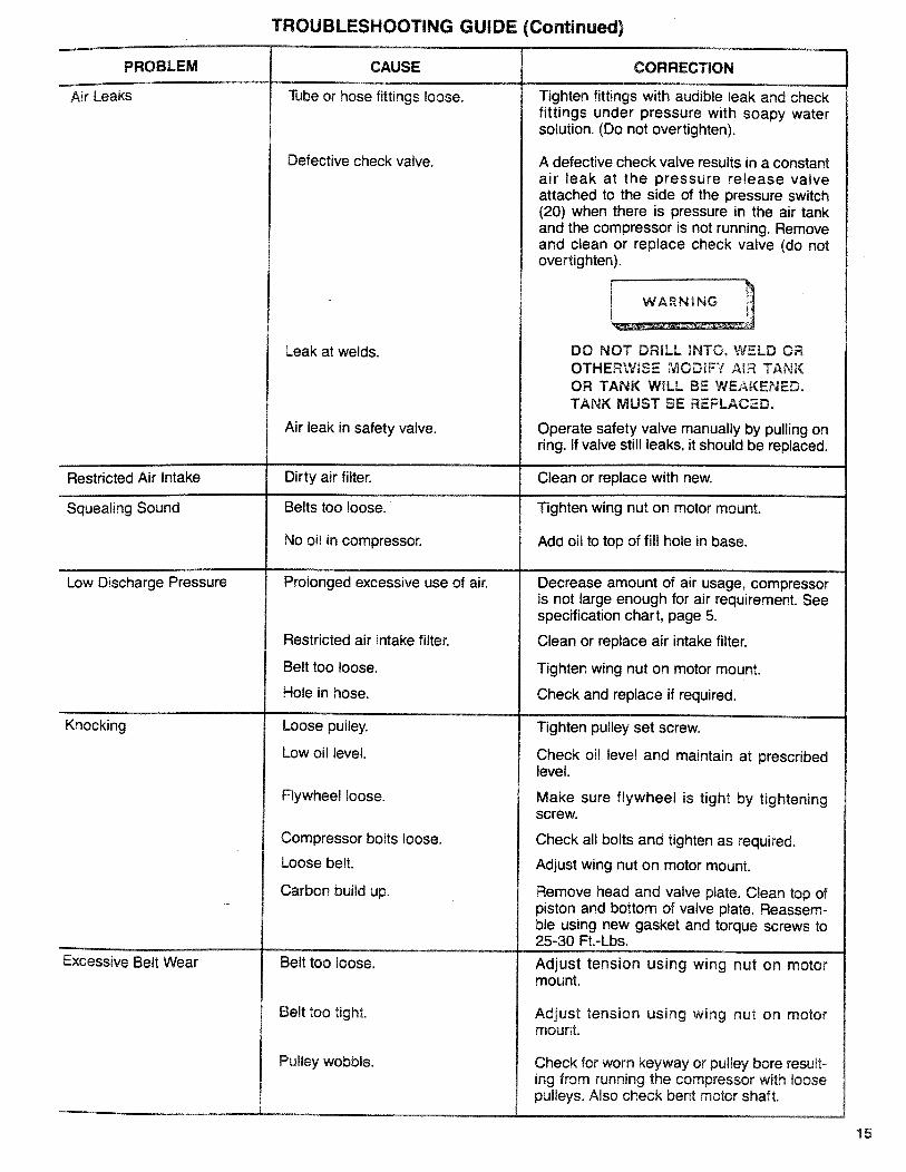
TROUBLESHOOTING GUIDE (Continued)
PROBLEM
Air Leaks
CAUSE
Tube or hose fittings loose.
Restricted Air Intake
Squealing Sound
Low Discharge Pressure
Defective check valve.
Leak at welds.
Air leak in safety valve.
Dirty air filter.
Belts too loose.
No oil in compressor.
Prolonged excessive use of air.
Restricted air intake filter.
CORRECTION
Tighten fittings with audible leak and checkfittings under pressure with soapy watersolution. (Do not overtighten).
A defective check valve results in a constantair leak at the pressure release valveattached to the side of the pressure switch(20) when there is pressure in the air tankand the compressor is not running. Removeand clean or replace check valve (do notovertighten).
DO NOT DR_LL INTO, WSLD OROTHERWISE MODIFY AIR TANKOR TANK WiLL BE WEAKENED.TANK MUST BE REPLACED.
Operate safety valve manually by pulling onring. If valve still leaks, it should be replaced.
Clean or replace with new.
Tighten wing nut on motor mount.
Add oil to top of fill hole in base.
Decrease amount of air usage, compressoris not large enough for air requirement. Seespecification chart, page 5.
Clean or replace air intake filter.
Knocking
Belt too loose.
Hole in hose.
Loose pulley.
Low oil level.
Flywheel loose.
Tighten wing nut on motor mount.
Check and replace if required.
Tighten pulley set screw.
Check oil level and maintain at prescribedlevel.
Make sure flywheel is tight by tighteningscrew.
Excessive Belt Wear
Compressor bolts loose.
Loose belt.
Carbon build up.
Belt too loose.
Belt too tight.
Pulley wobble.
Check all bolts and tighten as required.
Adjust wing nut on motor mount.
Remove head and valve plate. Clean top ofpiston and bottom of valve plate. Reassem-ble using new gasket and torque screws to25-30 Ft.-Lbs.
Adjust tension using wing nut on motormount.
Adjust tension using wing nut on motormount.
Check for worn keyway or pulley bore result-ing from running the compressor with loosepulleys. Also check bent motor shaft.
15

Sears
OWNERSMANUAL
SERVICE
MODEL NOS.919.174211919.174310919.174320919.174410
HOW TO ORDERREPAIR PARTS
AIR
COMPRESSOR
Now that you have purchased your Sears Air Compressor, should aneed ever exist for repair parts or service, simply contact any SearsService Center and most Sears, Roebuck and Co. stores. Be sureto provide all pertinent facts when you call or visit.
The model number of your Sears Air Compressor is 919 ____This number can be found on the label which is located on the frontof the tank saddle.
WHEN ORDERING REPAIR PARTS, ALWAYS GIVE THE FOL-LOWING INFORMATION:
• PART NUMBER• MODEL NUMBER
• PART DESCRIPTION® NAME OF ITEM
NOTE:
If service or repair parts are required for the motor, supply all motornameplate information including manufacturers.
All parts listed may be ordered from any Sears Service Center andmost Sears stores.
If the parts you need are not stocked locally, your order will beelectronically transmitted to a Sears Repair Parts Distribution Cen-ter for handling.
Sears, Roebuck and Co., Chicago, BL 60684 U.S.A.SI-30-!4-2 PRINTED IN US A


![Brochure2 - MagicBricks€¦ · Location Map School B sc Delhi Pub licSçh001 To 20 min 13 12 min 10 min 08 m] n 02 Temple AFMC 20 min 12 min IS min 10 min min IS min min 07 min](https://static.fdocuments.net/doc/165x107/6034384eb5808f20db6ba851/brochure2-magicbricks-location-map-school-b-sc-delhi-pub-licsh001-to-20-min.jpg)


