Sears - Appliance Parts · Sears owners manual MODEL NO. 113.299142 SAW ON LY 113.299040 SAW WITH...
44
Sears owners manual MODEL NO. 113.299142 SAW ON LY 113.299040 SAW WITH LEGS TWO TABLE EXTENSIONS AND MOTOR 113.298470 SAW WITH LEGS ONE TABLE EXTENSION AND MOTOR ;eria Number Model and serial number may be found at the left-hand side of the base. You should record both model and serial number in a safe place for future use. CAUTION: Read GENERAL and ADDITIONAL SAFETY INSTRUCTIONS carefully CRRFTSMRN+--_ IO-INCH TABLE SA W • assembly • operating • repair parts I Sold by SEARS, ROEBUCK AND CO., Chicago, IL. 60684 U.S.A. Part No. 62588 Printed in U.S.A,
Transcript of Sears - Appliance Parts · Sears owners manual MODEL NO. 113.299142 SAW ON LY 113.299040 SAW WITH...

Sears
ownersmanual
MODEL NO.113.299142
SAW ON LY
113.299040SAW WITH LEGS
TWO TABLE EXTENSIONSAND MOTOR
113.298470SAW WITH LEGS
ONE TABLE EXTENSIONAND MOTOR
;eriaNumber
Model and serial
number may be foundat the left-hand side
of the base.
You should record both
model and serial number
in a safe place forfuture use.
CAUTION:
Read GENERAL
and ADDITIONALSAFETY
INSTRUCTIONS
carefully
CRRFTSMRN+--_
IO-INCH TABLE SA W
• assembly
• operating
• repair parts
I
Sold by SEARS, ROEBUCK AND CO., Chicago, IL. 60684 U.S.A.Part No. 62588 Printed in U.S.A,

FULL ONE YEAR WARRANTY ON CRAFTSMAN TABLE SAWS
If within one y_ar from the date of purchase, this Craftsman Table Saw fails due to a defect in material or
workmanship, _e_r_ will repair, t, free of charge
Warranty service is available by simply contacting the nearest Sears store or Service Center throughout theUnited States.
This warranty gives you specific legal rights, and you may also have other rights which vary from state to
state. SEARS, ROEBUCK AND CO.BSC 41-3SEARS TOWERCHICAGO, I L 60684
GENERAL SAFETY INSTRUCTIONSFOR POWER TOOLS
1. KNOW YOUR POWER TOOLRead the owner's manual carefully, Learn itsapplication ano limitations as well as the specificpotential hazards peculiar to this tool.
2. GROUND ALL TOOLSThis tool is equipped with an approved 3-conductorcord and a 3-prong grounding type plug to fit theproper grounding type receotacle. The green conductorn the cord is the grounding wire. Never connect the
green wire to a live terminal.
3. KEEP GUARDS IN PLACEin working order, and in proper adjustment and
alignment.
4. REMOVE ADJUSTING KEYSAND WRENCHESForm habit of checking to see that keys and adjustingwrenches are removed from too! before turning it on.
5. KEEP WORK AREA CLEANCluttered areas and benches invite accidents. Floor
must not be slippery due to wax or sawdust,
6. AVOID DANGEROUS ENVIRONMENT
Don't use power tools in damp or wet locations orexpose them to rain. Keep work area well lighted,Provide adequate surrounding work space.
7. KEEP CHILDREN AWAYAll visitors should be kept a safe distance from workarea,
8. MAKE WORKSHOP KID-PROOF-- with padlocks, master switches, or by removingstarter keys.
9. DON'T FORCE TOOLIt will do the job better and safer at the rate for whichit was designed.
10. USE RIGHT TOOLDon't force tool or attachment to do a job it was notdesigned for.
11. WEAR PROPER APPARELDo not wear loose clothing, gloves, neckties or jewelry(rings, wrist watches) to get caught in moving parts.Nonslip footwear is recommended. Wear protectivehair covering to contain long hair. Roll tong sleevesabove the elbow.
12. USE SAFETY GOGGLES (Head Protection)Wear Safety goggles (must comply with ANS Z87.1) atall times. Also, use face or dust mask if cuttingoperation is dusty, and ear protectors (plugs or muffs)during extended periods of operation.
13. SECURE WORKUse clamps or a vise to hold work when practical. It'.ssafer than using your hand, frees both hands to operatetool.
14. DON'T OVERREACHKeep proper footing and balance at all times.
15. MAINTAIN TOOLS WITH CARE
Keep tools sharp and clean for best and safestperformance. Follow instructions for lubricating andchanging accessories,
16. DISCONNECT TOOLSbefore servicing; when changing accessories such asblades, bits, cutters, etc.
17. AVOID ACCIDENTAL STARTINGMake sure switch is in "OFF" position before pluggingin.
18. USE RECOMMENDED ACCESSORIESConsult the owner's manual for recommended
accessories. Follow the instructions that accompanythe accessories. The use of improper accessories maycause hazards.
19. NEVER STAND ON TOOLSerious injury could occur if the tool is tipped or if the
cutting tool is accidentally contacted.
Do not store materials above or near the tool such thatit is necessary to stand on the tool to reach them.
20. CHECK DAMAGED PARTSBefore further use of the tool, a guard or other part that
is damaged should be carefully checked to ensure that it
will operate properly and perform its intended function.Check for alignment of moving parts, binding of moving
parts, breakage of parts, mounting, and any otherconditions that may .affect its operation. A guard or
other part that is damaged should be properly repaired
or replaced.
21, DIRECTION OF FEEDFeed work into a blade or cutter against the directionof rotation of the blade or cutter only.
22. NEVER LEAVE TOOL RUNNINGUNATTENDEDTurn power off. Don't leave tool until it comes to acomplete stop,

ADDITIONAL SAFETY INSTRUCTIONSFOR TABLE SAWS
WARNING: FOR YOUR OWN SAFETY, DO NOTOPERATE YOUR SAW UNTIL IT IS COMPLETELYASSEMBLED AND INSTALLED ACCORDING TO THEINSTRUCTIONS ... AND UNTIL YOU HAVE READAND UNDERSTOOD THE FOLLOWING.
1. GENERAL SAFETY INSTRUCTIONS FOR POWERTOOLS... SEE PAGE 2
2. GETTING TO KNOW YOUR SAW... SEE PAGE 203. BASIC SAW OPERATION... SEE PAGE 234. ADJUSTMENTS... SEE PAGE 295. MAINTENANCE... SEE PAGE 326, STABILITY OF SAW
If there is any tendency for the saw to tip over or moveduring certain cutting operations such as cuttingextremely large heavy panels or long heavy boards, thesaw should be bolted down.
If you attach any kind of table extensions over 24 in.wide, make sure they are supported underneath bysturdy 0race attached to saw base or bench.
7. LOCATIONThe saw should be oositioned so neither the operatornor a casual observer is forced to stand in line with thesaw blade.
8. KICKBACKS
Kickbacks can cause serious injury: A "Kickback"occurs when a part of the workpiece binds between thesawblade and the rip fence or other fixed object, risesfrom the table, and is thrown toward the operator.Keep your face and body ;o one side of the sawblade,out of line with a possible "Kickback.'"Kickbacks - and possible injury from them - canusually be avoided by:A. Maintaining the rip fence oarallel to the sawblade.B. Keeong the sawblade sharp. Replacing
anti-kickback oawls when points become dull.
C. KeeDing_ sawblade guard, spreader, andanti-kickback pawls in place and o 0erating properly.The spreader must be in alignment with thesawblade anG the oawls must stop a <ickback once
it has started. Check their action before ripping.D. NOT ripping work that is twisted or warped or does
not have a straight eage to guide along the rip fence.E. NOT releasing work until you have pushed it all the
way oast the sawblade.F. Using a push stick for ripping widths of 2 to 6 in.,
and an auxiliary fence and push block for rippingwidths na-rower tnan 2 in. (See "Basic Saw
Operation Using The RiD Fence" section.)
G. NOT confining the cut-off piece when ripping orcross-cutting.
H. When ripping apply the feed force to the section ofthe workpiece between the saw blade and the ripfence.
9. PROTECTION: EYES, HANDS, FACE, EARS, BODYA. If any part of your saw is malfunctioning, has been
damaged or broken.., such as the motor switch, orother operat]n 9 control, a safety device or the
power cord ... cease operating immediately untilthe particular Dart is properly repaired or replaced.
B. Wear safety goggles that comply with ANSZ87.1-1968, and a face shield if operation is dusty.Wear ear plugs or muffs during extended periods ofoperation.
C. Small loose pieces of wood or other objects that
contact the rear of the revolving blade can bethrown back at the operator at excessive speed. Thiscan usually be avoided by keeping the guard and
spreader in 01ace for all thru-sawing operations(sewing entirely thru the workJ AND by removingall loose pieces from the table with a long stick of
wood IMMEDIATELY after they are cut off.D. Use extra caution when the guard assembly is
removed for resawing, dadoing, rabbeting, or
molding - replace the guard as soon as thatoperation is completed.
E. NEVER turn the saw "ON" _)efore clearing thetable of all tools, wood scraps, etc., except theworkpiece and related feed or support devices forthe operation planned.
F. NEVER place your face or body in line with thecutting tool.
G. NEVER place your fingers or hands in the path ofthe sawblade or other cutting tool.
H. NEVER reach in oack of the cutting tool witheither hand to hold down or support the workplece,remove wood scraps, or for any other reason. Avoidawkward operations and hand positions where asudden slip could cause fingers or hand to moveinto a sawblade or other cutting tool.
I. DO NOT perform layout, assembly, or setup workon the table while the cutting tool is rotating.
J. DO NOT perform any operation "FREEHAND"
always use either the rip fence or the miter gauge toposition and guide the work.
K. NEVER Use the rip fence when crosscutting or the
miter guage when ripping. DO NOT use the rip
fence as a length stop.Never hold ent0or touch the free end'" of the
workpiece or a "free piece'" that is cut off whilepower is "ON" and/or the sawblade is rotating.
L. Shtit "OFF" the saw and disconnect the power cordwhen ,removing the table insert, changin£ thecutting toot, removing or replacing the blade guard,or making adjustments.
M. Provide adeauate support to the rear and sides ofthe saw table for wider or tong workpieces,
N. Plastic and composition like hardboard) materialsmay be cut on your saw. However, since these areusually quite hard and slippery, the anti-kickbackpawls may not stop a kickback.Therefore, be especially attentive to followingproper set-up and cutting procedures for ripping.Do not stand, or permit anyone else to stand, in linewith a potential kickback.
O. If you stall or jam the sawblade in the workpiece,turn saw "OFF", remove the workDiece from thesawblade, and check to see if the sawblade s
parallel to the table slots or grooves ana if thespreader is n proper alignment with the sawblade.If ripping at the time, check to see if the rid fence isparallel with the sawblade. Readjust as indicated.
10. KNOW YOUR CUTTING TOOLS
A. Dull, gummy, or improperly sharpeneu or _et cuttingtools can cause materia to stick, jam, stall the saw,or kickback at the onerator.Minimize potential injury by proper cutting tooland machine maintenance.NEVER ATTEMPT TO FREE A STALLEDSAWBLADE WITHOUT FIRST TURNING THESAW OFF.

B. Never use grinding wheels, abrasive cut-off wheels,friction wheels (metal slitting blades) wire wheels orbuffing wheels.
11. USE ONLY ACCESSORIES DESIGNED FOR THIS
SAW,
12. Cross-cutting operations are more conveniently workedand with greater safety if an auxiliary wood facing isattached to the miter gauge using the holes provided,
13. Make sure the top of the arbor or cutting tool rotatestoward you when standing in norm_ operatingposition. Also make sure the cutting tool, arbor collarsand arbor nut are installed properly. Keep the cuttingtool as low as possible for the operation beingperformed. Keep all guards in place whenever _ossible.
14. Do not use any blade or other cutting tool marked foran operating speed less than 3450 RPM. Never use acutting tool larger in diameter than the diameter forwhich the saw was designed. For greatest safety andefficiency when ripping, use the maximum diameterblade for whicl_ the saw is designed, since under theseconditions the spreader is nearest the blade.
15. Adjust table inserts flush with the table top. NEVERoperate the saw unlessthe proper insert is installed.
16. THINK SAFETY.Safety is a combination of operator common sense andalertness at all times when the saw is being used.
17. NOTE AND FOLLOW SAFETY INSTRUCTIONSTHAT APPEAR ON THE FRONT OF YOUR SAW.
DANGER
FOR YOUR OWN SAFETYREAD AND UNDE RSTAND OWNER'S MANUAL
BEFORE OPERATING MACHINE:I. WEAR SAFETY GOGGLES2, USE SAW-BLADE GUARD FOR "THRU-SAWING"3. KEEP HANDS OUT OF PATH OF SAWBLADE4. USE A"PUSH-STICK" WHEN REQUIRED5. KNOW HOW TO AVOID "'KICKBACKS'"6. DO NOT PERFORM OPERATIONS "FREEHAND"
18. WARNING: DO NOT ALLOW FAMILIARITY(GAINED FROM FREQUENT USE OF YOUR SAW)TO BECOME COMMONPLACE. - ALWAYSREMEMBER THAT A CARELESS FRACTION OF ASECOND IS SUFFICIENT TO INFLICT SEVEREINJURY.
19. WARNING: THE 2-1/2" SAW PULLEY AND THE2-1/2" MOTOR PULLEY FURNISHED, WILL RUNTHE BLADE AT APPROXIMATELY 3450 RPMWHEN USED WITH A 3450 RPM MOTOR. NEVERSUBSTITUTE THESE PULLEYS TO INCREASE THISSPEED BECAUSE IT COULD BE DANGEROUS.
The operation of any power tool can result in foreignobjects being thrown into the eyes, which can result insevere eye damage. Always wear safety gogglescomplyingwith ANSI Z87.1 (shown on Package) before commencingpower tool operation. Safety Gogglesare available at Searsretail or catalog stores.
MOTOR SPECIFICATIONS ANDELECTRICAL REQUIREMENTS
This saw is designed to use a 3450 RPM motor only. Do notuse any motor that runs faster than '3450 RPM, It is wiredfor operation on 110-120 volts, 50 Hz., alternating current.IT MUST NOT BE CONVERTED TO OPERATE ON 230VOLTS. EVEN THOUGH SOME OF THERECOMMENDED MOTORS ARE DUAL VOLTAGE.
The outlet in the switch box will accept either a 15 amp. ora 20 amp. motor plug.
RECOMMENDED CRAFTSMAN MOTORS FOR USE ONTHIS SAW.
No.H.P. R.P.M. Volts Catalog
1 3450 110.120 12171 3450 110.120 1220
If power cord is worn or cut, or damaged in any way, haveit replaced immediately.
If your saw is for use on less than 150 volts it has a plugthat looks like below.
6
3-PRONG PLUG
GROUNDING PRONG
PROPERLY GROUNDED
3-PRONG OUTLET
See recommendation on saw for use in Canada
CAUTION: Do not use blower or washing machine motorsor any motor with an automatic reset overload protector astheir use may be hazardous.
CONNECTING TO POWER SOURCE OUTLET
This saw must be grounded while in use to protect theoperator from electrical shock.
Plug power cord into 110-120V properly grounded typeoutlet protected by a 15-amp. time delay or Circuit-Saverfuse or circuit breaker.
IF YOU ARE NOT SURE THAT YOUR OUTLET ISPROPERLY GROUNDED, HAVE IT CHECKED BY AOUALI FlED ELECTRICIAN.WARNING: DO NOT PERMIT FINGERS TO TOUCHTHE TERMINALS OF PLUG WHEN INSTALLING ORREMOVI_IG THE PLUG TO OR FROM THE OUTLET.

WARNING:IF NOT PROPERLY GROUNDED THISPOWER TOOL CAN INCUR THE POTENTIAL HAZARDOF ELECTRICAL SHOCK, PARTICULARLY WHENUSED IN DAMP LOCATIONS, IN PROXIMITY TOPLUMBING, OR OUT OF DOORS. IF AN ELECTRICALSHOCK OCCURS THERE IS THE POTENTIAL OF ASECONDARY HAZARD SUCH AS YOUR HANDSCONTACTING THE SAWBLADE.
This saw is equipped with a 3-conductor cord andgrounding type plug which has a grounding prong, approvedby Underwriters' Laboratories and the Canadian StandardsAssociation. The ground conductor has a green lug and isattached to the tool housing at one end and to the groundprong in the attachment plug at the other end.
This plug requires a mating 3-conductor grounded typeoutlet as shown.
If the outlet you are planning to use for this saw is of thetwo prong type DO NOT REMOVE OR ALTER THEGROUNDING PRONG N ANY MANNER. Use an adapteras shown and always connect the grounding lug to a knownground.
It is recommended that you have a qualified electricianreplace the TWO prong outlet with a properly groundedTHREE prong outlet.
An adapter as shown below is available for connecting plugs
to 2-prong receptacles. The green grounding lug extendingfrom the adapter must be connected to a permanent ground
such as to a properly grounded outlet box.
GROUNDING LUG
ADAPTER / / __._...
MAKE SURETHIS IS3-PRONG _ ..,,----- CONNECTED TO A
PLUGI _ KNOWN GROUND
RECEPTACLE
NOTE: The adapter illustrated is for use only if you alreadyhave a properly grounded 2-prong receptacle. Adapter isnot allowed in Canada by the Canadian Electrical Code.
The use of any extension cord will cause some loss ofpower. To keep this to a minimum and to preventover-heating and motor bum-out, use the table below todetermine the minimum wire size (A.W.G.) extension cord.Use only 3 wire extenston cords which have 3 pronggrounding type plugs and 3-pole receptacles which willacceot the plug on the saw.
1 H.P. MOTOR 110-120VExtension Cord Length Wire Size A.W.G.
Upto 50 Ft ................. 1450to 100 Ft................ 12100 - 200 Ft ................. 10
200 - 400 Ft. ................ 8
CHECK MOTOR ROTATION
WARNING: FOR YOUR OWN SAFETY, MAKE SUREPLUG IS NOT CONNECTED TO POWER SOURCEOUTLET. WHEN CHANGING MOTOR ROTATION,
The motor must rotate CLOCKWISE when viewed from theshaft end to which you will mount the pulley. (See page16.) If it does not, change the direction according to theinstructions furnished with the motor.
CONTENTS
WARRANTY ................................. 2
GENERAL SAFETY INSTRUCTIONSFOR POWER TOOLS ......................... 2
ADDITIONAL SAFETY INSTRUCTIONSFOR TABLE SAWS ........................... 3
MOTOR SPECIFICATIONS AND ELECTRICALREQUIREMENTS ............................ 4
UNPACKING AND CHECKING CONTENTS ........ 6Tools Needed ................................ 6List of Loose Parts ............................ 6
ASSEMBLY .................................. 7
Installing Tilt Crank .......................... 7Checking Table Insert ......................... 7Checking Blade Squareness to Table .............. 8Assembling Steel Legs ......................... 8Mounting Saw ............................... 9Attaching Table Extensions ..................... 9Installing Rip Fence Guide Bars ................. 10Aligning Rip Fence .......................... 12Adjusting Rip Scale Pointer .................... 13Repositioning Rip Fence Guide Bars ............. !3Installing Blade Guard ........................ 14Mounting the Motor ......................... 16Installing Belt Guard ......................... 18Plugging in Motor ........................... 19
GETTING TO KNOW YOUR SAW ............... 20On-Off Switch .............................. 20Elevation Crank ............................. 21Tilt Crank ................................. 21Tilt Lock Handle ............................ 21Rip Fence ................................. 21Miter Gauge ................................ 21Blade Guard ................................ 21Table Insert ................................ 21Removing and Installing Saw Blade .............. 22Exacti-Cut ................................. 22
BASIC SAW OPERATION USING THE MITER GAUGE23Work Helpers ............................... 23Crosscutting ................................ 24Repetitive Cutting ........................... 24Miter Cutting ............................... 25Bevel Crosscutting ........................... 25Compound Miter Cutting ...................... 25
BASIC SAW OPERATION USING THE RIP J:ENCE .. 26Ripping ................................... 26Bevel Ripping .............................. 26Resawing .................................. 28Cutting Panels .............................. 28Rabbeting ................................. 28
ADJUSTMENTS .............................. 29Miter Gauge ................................ 29Heeling Adjustment or Parallism ofSawblade to Miter Gauge Groove ............... 29
Blade Tilt, or Squareness ofBlade to Table ............................. 30
Tilt Mechanism ............................. 32
MAINTENANCE ............................. 32LUBRICATION .............................. 33
RECOMMENDED ACCESSORIES ............... 33TROUBLE SHOOTING ........................ 34
REPAIR PARTS .............................. 36

UNPACKING AND CHECKING CONTENTS
/_ TOOLS NEEDED
M_dia__nscSrCrew_ dri_rer
P.ers_U_IU II1. , .... Wrenches
_i..'i:!.':i.i:,'i'.i;,!:iii['.:_) '.),( '.),: i ',:-i,_' j 3/8 in. 7/16 n.1/2 in. 9/16 in.
Combination Square 3/4 in.
Model 113.299142 Table Saw is shipped complete in onecarton but DOES NOT INCLUDE Table Extension, SteelLegs, or motor.
Model 113.299040 Table Saw is shipped complete in onecarton but INCLUDES Two Table Extensions, Steel Legs,and Motor.
Model 113.298470 Table Saw is shipped complete in onecarton but INCLUDES One Table Extension, Steel Legs,and Motor.
Separate all parts from packing materials and check eachone with the illustration and the list of Loose Parts to make
certain all items are accounted for, before discarding anypacking material.
If any parts are missing, do not attempt to assemble thetable saw, plug in the power cord or turn the switch onuntil the missing parts are obtained and are installedcorrectly.
Remove the protective oil that is applied to the table topand edges of the table. Use any ordinary household typegrease and spot remover.
CAUTION: Never use gasoline, naptha or similar highlyvolatile solvents.
Apply a coat of automobile wax to the table.
Wipe all parts thoroughly with a clean, dry cloth.
WARNING: FOR YOUR OWN SAFETY, NEVERCONNECT PLUG TO POWER SOURCE OUTLET UNTILALL ASSEMBLY STEPS ARE COMPLETE, AND YOUHAVE READ AND UNDERSTAND THE SAFETY ANDOPERATIONAL INSTRUCTIONS.
_1 2 _3
I L '
11 10 9
COMBINATION SQUARE MUST BE TRUE.
DRAW LIGHT LINE ON
STRAIGHT EDGE OF BOARD3/'4 THICK. EHIS EDGE MUST
BE PERFECTLY SI_AIGHT.
BOARD ALONG THIS_ f I"EDGE" _\ _ /
L.
/S_OULD BE NO nAP Off OVERLAP
HERE WHEN SQUARE IS FLIPPEDOVE_: N DOTTED POSITION.
LIST OF LOOSE PARTSKeyNo. PartName Qty.
1 BladeGuardandSpreader .................... 1
2 Rip Fence ................................ 13 OwnersManual ............................ 1
4 Miter Gauge ............................... 15 Arbor Nut Wrench .......................... 1
6 Switch ................................... 1
7 RipFenceGuide Barwith Rip Scale(Front) ...... 1B Crank .................................... 19 V-Belt 1/2 in. x41 in........................ 1
10 Pulley,2-I/2 in. dia.,with 5/8 in.bore ........... 1
11 Belt andPulleyGuard ....................... 1
12 Belt GuardClip ............................ 3
13 Self-ThreadingScrew,10-32x 1/2inJong ....... 214 Belt GuardSupport ......................... 1
15 Belt GuardSupportBracket ................... 1
16 Motor Base .................................
17 SpreaderRod .............................. 1
18 Blade GuardSupport with Screw ............... 1
19 SpreaderSupport ........................... 1
20 RipFenceGuideBar (Rear) ................... 1
21 RipFenceGuideBar Rod .................... IPkg.of MiscellaneousSmallPartsNo. 62586
Consistingof the Following:22 SetscrewWrench,3/32 in.................. 122 SetscrewWrench,1/Bin................... 1
22 SetscrewWrench,5/32 in............... 1
SIZE 23 24 2 TH
26 27
2s _
_30 31_'
31

KeyNo, Part Name
23
24
25
25
25
25
26
26
27
27
28
29
30
31
32
_ty.
Switch Key ............................ 2
Self-ThreadingNut ....................... 2
Hex HeadScrew,5/16 in.-18 x 1-1/2 in.long .. 2
Hex HeadScrew,5/16 in.-18 x 5/8 inJong .... 3
Hex HeadScrew,5/16 in.-18 x 1 in.long ..... 4
Hex HeadScrew,1/4 in.-20 x 5/8 in.long ..... 2Hex Nut, 5116in.-18
(approx.dia. of hole5/16 in.) ............. 8Hex Nut, 1/4 in.-20
(approx.dia. of hole1/4 in.) .............. 2
Lockwasher,5/16 in. ExternalType(approx.dia. of hole5/16 in.) ............. 10
Lockwasher,1/4 in, ExternalType(approx.dia. of holeI/4 in.) .............. 2
CarriageBolt, 5/16 in.-18 x 3/4 in.long ...... 4
Rip FenceGuideBarSpacer ............... 2
Cord Clamp ............................ 2
PanHeadSheetMetalScrews,3/8 in.long ..... 2
Thumbscrew,5/16 in.-18 x 1 in. long ........ I
The following parts are included with Model 113.299040and 113.298470
1 Leg ..................................... 4
2 SideStiffener ............................. 2
3 EndStiffener ............................. 2
4 TableExtension(113.299040) ............... 2
TableExtension(113.298470) ............... I
Pkg.of MiscellaneousSmall Parts,No. 82591
Consistingof the Following:5 Hex HeadScrewS/16in.-18x1-1/4in. long ... 12
6 Lockwasher,1/4 in. ExternalType(approx. dia.of hole 1/4 in.) ............... 24
6 Loekwasher,5/16 in. ExternalType(approx. dia.of hole5/16 in.) .............. 12
!5
©$
KeyNo.
7
7
7
8
9
1011
9
4
10 11
Part Name Qty.
Hex Nut, 1/4 in. - 20(approx.dia. of hole 1/4 in.) ............... 24
Hex Nut, 5/16 in.- 18(approx.dia. of hale5/15 in.) ............. 12
Hex Nut, I/2 in.- 13(approx.die. of hole 1/2 in.) ............... 8
FlatWasher(dia. of hole, 11/32 in.) .......... 8
TrussHeadScrew,1/4 in,- 20 x 5/8 in. long(top of screwisrounded) ................. 24
LevelingFoot ........................... 4Motor ................................... 1
ASSEMBLYBefore mounting the saw on legs, a stand or a bench, theTable Insert and Blade Squareness must be checked at thistime.
INSTALLING TILT CRANK
1, Line up set screw in crank with FLAT SPOTS on shaft... tighten screws using 1/8 in. set screw wrench
furnished with saw.
CHECKING TABLE INSERT
2. Insert should be flush with table top. Check as shownand adjust the four setscrews as necessary.
3/32 IN.SETSCREWWRENCH
TABLE NSERT J

\
\
CZ>
/
3.
4.
Insert forefinger into table-insert slot and pull upwardto remove insert.
Replace nsert. If clips do not hold insert securely,remove insert end bend clips.
SPRING CLIP
/ -.
-- I /
_ (\" t "_ BEND CLIPS
k,.__" AS NEEDED
t.._ SPRING CLIP
CHECKING BLADE SQUARENESS TO TABLE
IMPORTANT: BLADE must be SQUARE (g0°) toTABLE, in order to proceed with assembly.
1. Turn ELEVATION crank clockwise until blade is up ashigh as it will go.
2. Check for BLADE SQUARENESS ... if blade is notsquare to table, adjust it at this time.
NOTE: The combination square must be "true" - seestart of "Unpacking and Checking Contents" Section onpage 6 for checking method.
Refer to "BLADE TILT, OR SQUARENESS OF BLADETO TABLE" adjustments on page 30.
MAKE SURE SQUARE
IS NOT [OUCHING
TIP OF TOOTH
ASSEMBLING STEEL LEGS
NOT SUPPLIED IN CANADA
NOTE: Steel Legs ere furnished with Model 113.299040and 113.298470. From among the loose parts, find thefollowing Hardware:
24 Truss Head Screws, 1/4 in. - 20 x 5/8in. long (top ofscrew is rounded)
24 Lockwashers, 1/4 in. External Type (approx. dia. ofhole 1/4 in.)
24 Hex Nuts, 1/4 in. - 20 (approx. dia. of hole 1/4 in.)
8 Hex Nuts. 1/2 in. - 13 (approx. dia. of hole 1/2 in.)
4 Leveling feel
Assemble the legs as shown ...
1. Insert the Truss Head Screws through the holes in thelegs, then through the holes in the stiffeners. MAKESURE THE SCREWS GO THROUGH THE HOLES NTHE SIDE STIFFENERS MARKED "'X".
2. Install the Iockwashers ... screw on the nuts but do
not tighten until completely assembled.
3. Install leveling feet.
END
STIFFENER"
SIDE STIFFENER
IN. HEX NUTS
__._..----- LEVELING FOOT
8

MOUNTING SAW
1. From among the loose parts, find the followinghardware:
4 Hex Head Screws, 5/16 in. - 18 x 1-1/4 in. long.4 Hex Nuts, 5/16 in, - 18 (approx. dia. of hole 5/16 in.)4 Lockwashers, 5/16 in. External Type (approx. dia. ofhole, 5/16 in,)8 Flat Washers, (dia. of hole 11/32 in.)
2. Place saw on legsso that holes in bottom of saw line upwith holes in top of legs.
3. nstall screws, washersand nuts asshown.
SAW BASE
HEX HEAD SCREW
-,..,
//
FLAT
END
STIFFENER-"_j
FLAT WASHE
HEX
If you mount the saw on any other bench, make sure thatthere is an opening in the top of the bench the same size asthe opening in the bottom of the saw so that the sawdustcan drop through. Recommended working height is 33 to37 inches from the top of the saw table to the floor.
13
2-3/4
_I-V4
7/16 DIA. HOLES
/
OPENING
16 13
/ \\ ®
// \ \ ,.,,-FRONTOF SAW I/2
NOTE: All dimensions in inches
ATTACHING TABLE EXTENSIONS
If you received Table Extensions with your saw (twofurnished with Model No. 113.299040 or one furnishedwith Model No. 113.298470) attach them at this time.
If you have only one Table Extension, it may be attachedto either side.
NOTE: When the Table Extension is attached to the leftside, it offers more support to the workpiece, especiallywhen crosscutting or mitering long boards. When attachedto the right side, it offers more support when cutting widepanels.
If you attach the Extension to the left side, be sure toconstruct the Auxiliary Fence/Work Support and PushBlock shown on page
1. From among the loose parts find the followinghardware;
8 Hex Head Screws 5/16 in. - 18 x 1-1/4 in. long8 Lockwashers, 5/16 in. External Type (approx. dia. ofhole 5/16 in.)
8 Hex Nuts, 5/16 in. - 18 (approx. dia. of hole 5/16 in.)
Insert screws through holes in EXTENSION then throughtable. Install Iockwashers and screw on the nuts ... DONOT TIGHTEN.
BLOCK OF WOOC\
/I
Align front edge of extension with front edge of saw table.Pull Extension UPWARDS above table surface ..SLIGHTLY TIGHTEN SCREWS using I/2 in. wrench.Using small block of hardwood and hammer, tap extensionDOWNWARDS at front, center & rear, until it is EVENwith table surface ... TIGHTEN SCREWS,

Lay REARFENCE GUIDE BAR on table to act as astraightedge. If outer edge of extension is higher or lowerthan table surface;
A. Slightly loosen nuts holding bracket to extensionusing 7/16 in. wrench.
B. Move end of extension up or down until outer edgeis even with table surface ... check with GUIDE
BAR ... tighten nuts.C, Recheck INNER edge of extension to make sure it
has not moved ... readjust, if necessary,
INSTALLING RIP FENCE GUIDE BARS
I. From among the loose parts find the followinghardware:
2 Hex. Head Screws, 5/16 in. - 18 x 1-1/2 in. long2 Hex. Head Screws, 5/16 in. - 18 x 1 in. long
4 Hex. Nuts, 5/16 in. - 18 (approx, dia. of hole 5/16in.)
4 External Lockwashers, 5/16 in. (approx. dia. of hole5/16 in.)
2 Spacers, 3/4 in. dia. x I/2 in. long
2 Self-threading nuts2. Lay guide bars on table.
NOTE: The various holes in the bars allow them to berepositioned on the saw and also makes them adaptableto other models.
3. Insert 1-1/2 in. long screw through the THIRD holefrom the LEFT IN THE FRONT BAR ... insert
another 1-1/2 in. long screw through LARGE hole in
SWITCH BRACKET then through SEVENTH hole inbar. Hold them in place with a piece of masking tapefrom the underside.
4. Place spacerson screws.
Insert bolts through holes in middle and on right side offront of saw table ... instal Iockwashers and nuts.DON'T SCREW NUTS ON ALL THE WAY, just getthem started on the screws.
6. Remove the 3 screws from rear of table extension.
7. Insert 1 in. long screws in SECOND and FOURTH holesof rear bar and attach to tabSe the same way.
8. Insert ends of FENCE GUIDE BAR ROD throughround holes at outer end of bars.
NOTE: The ends of the ROD are not threaded ... theSELF THREADING NUTS will cut threads on the rodas they are screwed on.
]0
9. Holdrodwithonehandandwitha7/16(n.wrenchorpliersstartscrewingonONEof thenutsonlyATURNORTWO... screwonothernutthesameway.
10.UsingTWO7/16in.wrenchesorplierstightenbothofthenuts.
11. Slide the bars so that screws are in the MIDDLE of theslotted holes.
12. Position rip fence over miter gauge groove, holding upthe rear end while engaging front end with bar ...lower fence onto table.
13. Raise blade all the way up.
14. Carefully move fence against blade.
15. Move front bar until "0" mark on rip scale isapproximately at tip of pointer.
16, Move FRONT bar upwards until fence is approximately1/32 in. above table ... tighten screw at left end ofbar.
NOTE; Fold a piece of newspaper making 8 thicknessesand place between rip fence and table to act as a spacer.This will hold the fence off of the table approx. 1/32In.
17. Adjust rear bar so that the fence is approximately 1/32'n. above table make sure it is square with fence guidebar rod ... tighten screw at end of bar.
18. Replace screws in rear of table extension .., be suretop surface of extension is PARALLEL to top surfaceof rear guide bar.
8 THICKNESSESPAPF.,R
\
\
19. Move fence to RIGHT edge of table ... make sure it isapprox. 1/32 in. above table at front and rear andtighten screws,
11

ALIGNING RIP FENCE
The fence should slide easily along the bars and alwaysremain in alignment (parallel to sawblade and miter gaugegrooves).
The alignment is ,maintained by a spring underneath thefence which bears against the front guide bar.
To move the fence, loosen the lock handle and grasp thefence with one hand at the front,
For very close adjustments, grasp the guide bar wi;_h bothhands and move the fence with your thumbs.
Place fence on saw but DO NOT LOCK IT.
Move the REAR END of the fence slightly to the right orleft ... when you release it, the fence should "spring"back to its original position.
If it does not, the spring pressure must be INCREASED.1. Loosen the screws.
2. Move Spring slightly toward front of fence.
12
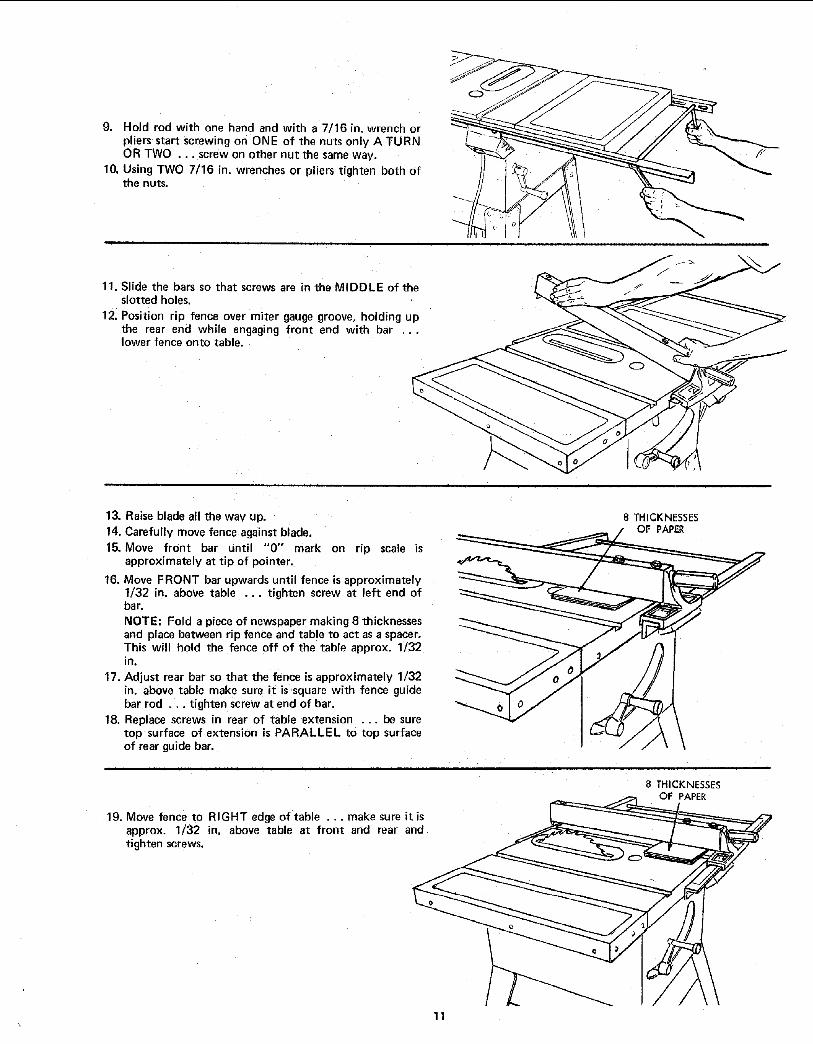
If the fence does not slide easily along the bars, the pressureof the spring can be REDUCED.1. Loosen the screws.
2. Move spring slightly toward rear of fence ... tightenscrews.
SPRING
SCREWS'
& The rip fence must be PARALLEL with the sawbladeand Miter Gauge grooves .,, Move fence until it isalong sideof groove, Do NOT LOCK IT. It should beparallel to groove, If it is not;A. Loosen the two "Hex, Head Screws."
B. Hold fence head tightly against bar ... move endof fence so that it is parallel with groove.
C. Alternately tighten the screws.
HEX SCREWS
FENCE HEAD
ADJUSTING RIP SCALE POINTER
1. Turn ELEVATION crank counterclockwise until blade
is up as high as it will go.
IMPORTANT: BLADE must be SQUARE (90 ° ) toTABLE, in order to ALIGN rip fence.
2. Position fence on right side of sawblade so that ittouches the sides of the teeth ... tighten lock handle.
3. Loosen screw holding the pointer ... adjust pointer sothat it points to "0'" ... tighten screw.
NOTE: If you cannot adjust pointer so that it points to"0", loosen the screws holding the front guide bar andmove the guide bar.
LOCK HANDLE
REPOSITIONING RIP FENCE GUIDE BARS
NOTE: If most of your work does not require 24 in. of ripcapacity, the bars may be reposi tioned to allow 12 in. of ripcapaGity to the right, or 10-1/2 n. to the left. The rip scale,however, only reads to the right.
There is a second set of numerals reading from 0 to 12 in.to the right which can be used when the rails arerepositioned.
1. Attach FRONT bar by inserting bolts through FIFTHand NINTH holes in bar and through RIGHT and LEFTholes in table.
_ o 1-...__!
13

2. Attach REAR bar using SIXTH and EIGHTH holes inbar.
NOTE: Remove screws from Table Extensions ... the ones
closest to the table. Reinstall them after attaching guidebar. If extension is used on right side of saw, remove theGuide Bar Rod.
t -J
/1 _/-- "----_
INSTALLING BLADE GUARD
1. From among the loose parts, find
2 Hex Head Screws, 1/4 in. - 20 x 5/8 in. long2 Hex Head Screws, 5/16 in. - 18 x 5/8 in. long
2 Hex Head Screws, 5/16 in. - 16 x 1 in. long
2 Hex Nuts, 1/4 in, - 20(approx. dia. of hole 1/4 in.)
2 Lockwashers, 1/4 in. External Type(approx. dia. of hole 1/4 in.)
2 Lockwashers, 5/16 in. External Type(approx. dia. of hole 5/16 in.} ....
1 Thumbscrew
Blade Guard SupportSpreader Support
Spreader Rod2. Lower the blade.
3. Screw the two MOTOR MOUNT CLAMP SCREWS partway into cradle.
4. Attach BLADE GUARD SUPPORT ... DO NOTTI GHTEN screws.
LADE
Insert SPREADER ROD into SPREADER SUPPORTuntil pin fits into notch. Insert Thumbscrew and tightenit.
SPREADER
ROD\
FLATSURFACE
(INTO SUPPORT)
u
SPREADERSUPPORT
14

1/4-20HEXHD.SCREW
I/4 IN.LOCKWASHER1./4-20HEXNUT
6. Slide SPREADER ROD into BLADE GUARDSUPPORT until end of ROD is even with edge ofSUPPORT .. • Tighten Hex Head Screw in support,
7. Attach SPREADER to SPREADER SUPPORT so thatscrews are all the way back in the SLOTS of SUPPORT• .. tighten screws.
8• Raise ANTI-KICKBACK PAWL (hold it in place with apiece of masking tape)
•.. align spreader SQUARE to table•.. Tighten both HEX HEAD SCREWS.
END OF ROD
EVEIN WITH
OF SUPPORT
SCREWS ALL THE JWAY BACK IN SLOTS I
IN SUPPORT
9. Raise blade all the way up ... make sure it is squarewith table•
10. Raise Blade Guard ... lift up bothANTI-KICKBACKPAWLS ... insert one of the SETSCREW WRENCHESin the notches to hold the pawls out of the way.
11. Lay blade of square or other straightedge alongside ofblade•
12. Loosen Hex Head Screw in BLADE GUARD SUPPORTand move spreader so that i1 touches blade of square•., tighten screw.
13. NOTE: The spreader is now square with the table andapproximately in line with the sawblade. The spreaderrequires further adjustment to align it PARALLEL tothe blade and in the MIDDLE of the cut (KERF) madeby the sawblade•
\
14. IMPORTANT: The SPREADER must always bePARALLEL to the sawblade and in the MIDDLE of thecut (KERF) made by the sawblade.
NOTE: The spreader is thinner than the width of theKERF by approximately six thicknesses of paper.
!SPREA
SPACEEQUAL TO APPROX.3 THICKNESSESOF PAPER KERF WOOD
BLADE
[
SPACE EQUAL TO APPROX. LOOKING DOWN ON SAW3 THICKNESSES OF PAPER
15

15. Make two folds in a small piece (6 x 6 in.) or ordinaryN EWSPAPE R making three thicknesses.
The folded paper will be used as a "'spacing gauge".
FOLDED PAPER
16. Place RIP FENCE on table ...
CAREFULLY move it against blade so that it is parallelto the blade, and just TOUCHES tips of saw teeth ...tighten RIP FENCE LOCK KNOB HANDLE.
17. Insert folded paper between SPREADER and FENCE•.. bold spreader flat against fence ... tighten screwsusing 7/16 in. wrench.
18. To remove BLADE GUARD AND SPREADER, loosenTHUMBSCREW ... DO NOT LOOSEN OTHERSCREWS.
7/16
/MOUNTING THE MOTOR
NOTE: Motor is included with Mode] 113.299040 and113.298470•
CHECK MOTOR ROTATION
1. The motor must rotate CLOCKWISE when viewed fromthe 5/8 in. shaft.
2. MAKE ,SURE "KEY" IS REMOVED FROM SHAFT.
3. Place the motor on your workbench or on the floor•
4. Stand clear of the motor and plug the cord into aproperly grounded outlet (See "Motor Specificationsand Electrical Requirements" Section) Notice therotation of the pulley. If it is not turning CLOCKWISE,REMOVE the plug from the outlet, and change therotation of the motor according to the instructionsfurnished with the motor.
ROTATION
/SIN. _:
DIA, SHAFT
WARNING: FOR YOUR OWN SAFETY, MAKE SUREPLUG IS NOT CONNECTED TO POWER SOURCEOUTLET WHEN CHANGING MOTOR ROTATION.
5. From among the loose parts, find the followinghardware:
4 Carriage Bolts, 5/16 in. - 18 x 3/4 in. long
4 Hex. Nuts, 5/16 in. - t8(approx. dia. of hole 5/16 in.)
4 Lockwashers, 5/16 in. External Type(approx. alia. of hole 5/16 in.)
6. Remove Blade Guard and Spreader.
7. Place motor on MOTOR BASE ... insert bolts throughholes in base ... then through the motor. InstallIockwasbers, and nuts.
8. Position motor so that edge of MOTOR- FOOT andMOTOR BASE are even .... slide motor all the way tothe RIGHT ... Lighten the four nuts.
g. Loosen set screw in motor pulley using 5/32 in.setscrew wrench. Slide pulley on shaft with HUB awayfrom motor. DO NOT TIGHTEN SETSCREW.
10. Install 3/16 in. square key (furnished with motor) ingrooves in pulley and motor shaft. DO NOT TIGHTENSETSCREW.
LOCKWASHER THESE TWO CARRIAGE BOLT
5/16 IN. EDGES EVE_4 5/16-t8 X 3/4 "4.
NUT I
5/16-18 J.... j '_
GUARD
K_Y
BASE
MOTOR MOUNTINGBASE
ULLEY
16

11. Lift motor and insert the TWO PINS on motor baseinto HOLES in cradle ... push motor in as far as it willgo.
12. Lower the blade...install belt on saw pulley and motorpulley,
13. Sight along edges- of both pulleys and move motorpulley so that belt is parallel to the edges of bothpulleys...tighten the setscrew in the motor pulley.
14. IMPORTANT: Measure the distance from end of motor
shaft to pulley...mark this dimension down; you willneed it later when reinstalling the pulley.
15. Make sure blade is g0 ° to table . . .raise i_allthe wayup.
16. Lift motor until edge of washer is even with end of slot... tighten pivot screw, In this position, pull motortoward you (pins will slide out of cradle) until belt isTIGHT ... tighten the two MOTOR BASE CLAMPSOREWS.
17. Loosen Pivot Screw slightly.
18. Lower the saw blade all the way down.
19. IMPORTANT: Motor should pivot freely downward asblade is lowered, If it does not, LOOSEN the PIVOTSCREW some more.
20. Pivot screw must be adjusted only tight enough to allowmotor to pivot FREELY as blade is raised or lowered.This will maintain constant tension on belt.
EDGE OF WASHEFEVEN WITH END
OF SLOT
PIVOT SCREW
MOTOR PULLEY "_
BASECLAMP SCREWS_
21. Loosen the two MOTOR CLAMP SCREWS on each endof motor. Rotate the motor so that the CAPACITOR
COVER is on top,..tighten the screws. The ventilationholes are now facing downward which will help preventsawdust from entering motor.
CAPACITO_COVER
\
VENTILATIONHOLES MOTOR
CLAMP SCREW
• (BOTH ENDS)
17

INSTALLING BELT GUARD
1. Remove the belt and motor pulley.2. Screws furnished with guard are "self threading" ..
screw them into holes in BELT GUARD SUPPORTBRACKET, then remove them.
3. Position BELT GUARD SUPPORT BRACKET andBELT GUARD SUPPORT as shown and install thescrews ... make sure motor shaft is in CENTER ofhole in SUPPORT.
BELT GUARD
SUPPORT BRACKET
TWO HOLES CLOSEST
TOGETHER
10-32 X I/2 fIN
\BELT GUARD SUPPORT
BELT GUARD
\PIVOT
SCREW
CENT£RED
Install three CLIPS (furnished with guard) 90° apartstarting with one clip at the end of the guard asshown•.. LONG END of clip facing AWAY from you.
BELT GUARD
OPENING/
CLIPS
\LONG END
5. Reinstall motor pulley the same way it was when youaligned the belt.
6. Place belt on SAW'PULLEY ... insert end of beltthrough opening in END of guard.
7. Slip belt over motor pulley.
18

Press guard onto support so that bottom of guard isapproximately 3/4 in. away from belt.
NOTE: To remove guard, lift up on LONG TABS ofcl ps ... pull guard outward. The clips should remainon the BELT GUARD SUPPORT.
IN.
PLUGGING IN MOTOR
1. From among the loose parts, find two Pan Head SheetMetal Screws, 3/8 in. long, and two cord clamps.
2. Attach clamps to right side of saw cabinet.
3. Route motor cord and power cord inside of clamps.4. Plug motor cord into outlet on back of switch box.
CORD CLAMPS
19

GETTING TO KNOW YOUR SAW
TABLE INSERT
MTERGAUGE 10 EXACT,CUTLOCK HANDLE_ \
MITER GAUGE
SAWBLADE
BLADE GUARD
ANTI-KICKBACKPAWLS
RIP FENCE
RIP FENCE
LOCK HANDLE
TILT LOCK HANDLE
(UNDERNEATH TABLEt
ELEVATI6N CRANK
\ON-OFF SWITCH
1 ON-OFF SWITCH
CAUTION: Before turning switch on, make sure the bladeguard is correctly installed and operating properly.
The On-Off Switch has a locking feature. THIS FEATUREIS INTENDED TO PREVENT UNAUTHORIZED ANDPOSSIBLE HAZARDOUS USE BY CHILDREN ANDOTHERS.
B. TO turn saw ON . .. stand to either side of theblade never in line with it ... insert finger underswitch lever and pull END of lever out.
After turning switch ON, always allow the blade tocome up to full speed before cutting.Do not cycle the motor switch on and off rapidly,as this may cause the sawblade to loosen. In theevent this should ever occur, allow the sawblade tocome to a complete stop and retighten the arbornut normally, not excessively. Never leave the sawwhile the Dower is "ON".
C. TO turn saw OFF ... PUSH lever in. Never leavethe saw until the cutting tool has come to acomplete stop.
D. TO lock switch in OFF position .. hold switch INwith one hand ... REMOVE key with other hand.
WARNING: FOR YOUR OWN SAFETY, LOWERBLADE OR OTHER CUTTING TOOL BELOWTABLE SURFACE. (IF BLADE IS TILTED,RETURN IT TO VERTICAL (90 ° } POSITION).ALWAYS LOCK THE SWITCH "OFF". WHENSAW IS NOT IN USE ... REMOVE KEY ANDKEEP IT IN ASAFE PLACE ... ALSO ,.. INTHE EVENT OF A POWER FAILURE (ALL OFYOUR LIGHTS GO OUT) TURN SWITCH OFF... LOCK IT AND REMOVE THE KEY. THIS
WILL PREVENT THE SAW FROM STARTING UPAGAIN WHEN THE POWER COMES BACK ON.
2O
\TILT CRANK
@KEY
(YELLOWPLASTIC)
KEY
J

2 ELEVATION CRANK ... elevates or lowers the blade.Turn clockwise to elevate ... counterclockwise tolower.
3 TILT CRANK ... tilts the blade for bevel cutting,Turn clockwise to tilt toward left ... counterclockwise
to tilt toward right,
When the blade is tilted to the LEFT as far as it will go,it should he at 45 ° to the table and the bevel pointershould point 45 °.
NOTE: There are LIMIT STOPS inside the saw which
prevent the blade from tilting beyond 45 ° to the LEFTand 90 ° to the RIGHT. (See "Adjustments" section
"Blade Tilt, or Squareness of Blade to Table").
4 TILT LOCK HANDLE ... locks the blade in thedesired tilt position. To loosen, turn counterclockwise.Push handle in and turn it to another position ifnecessary in order to tighten or loosen.
RIP FENCE . . is locked in place by tightening thelock handle. To move the fence, loosen the handle andgraspthe fence with one hand at the front.
Holes are provided in the rip fence for attaching a woodfacing when usingthe dado head, or molding head.
Select a piece of smooth straight wood approx. 3/4 in.thick and the same size as the rip fence.Attach it to the fence .with three Round Head _10Wood Screws 2 in. long. To remove the facing, loosenthe screws, slide the facing forward and pull the screwsthrough the round holes.
WOOD FACING
\
• \
-.. / ///", _OLND HEAD /
'_10WOOD SCREWS
6 MITER GAUGE . . head is locked in position forcrosscutting or mitering by tightening the lock handle,ALWAYS LOCK IT SECURELY WHEN IN USE.
There are two holes for the stop pin at the 45 degreerign_ and left positions for conveniently setting theMiter Gauge to cut miters.NOTE: The holes for the stop pin and the graduationsare manufactured to very close tolerances whichprovide accuracy for average woodworking. In somecaseswhere extreme accuracy is required, when makingangle cuts, for example, make a trial cut and thenrecheck it.
If necessary, the miter gauge head can then be swiveledslightly to compensate and then locked.
Holes are provided in the miter gauge for attaching anAUXILIARY FACING to make it easier to cut long
pieces.
Select a suitable piece of smooth straight wood ...drill two holes through it and attach it with smallscrews and nuts. The nuts go inside of the miter gauge.Or drill 1/4 in. holes all the way through the head. Thenyou can attach the facing with wood screws.
NOTE: When bevel crosscutting, attach facing so that itextends to the right of the miter gauge and use themiter gauge in the groove to the right of the blade.
AUXILIARY FACING
S!UTTING,
5TOP PIN 45 ° HOLEFORSTOP PIN
BLADEGUARD must always be in place and workingproperly for all thru-sawing cuts. That is, all cutswhereby the blade cuts completely through theworkpiece.
To remove the guard for special operations, loosen thethumbscrew and slide the guard off of the rod. DONOT DISTURB THE SETTING OF THE ROD.
When replacing the guard, make sure the PIN in the rodengages with the NOTCH in the spreader support. Makesure thumbscrew is tightened securely.
8 TABLE INSERT is removable for removing or installingblades or other cutting tools.
/
/
WARNING: FOR YOUR OWN SAFETY, TURNSWITCH "OFF" AND REMOVE PLUG FROMPOWER SOURCE OUTLET BEFORE REMOVINGINSERT.
A. Lower the blade below the table surface.
B, Raise blade guard.C. Lift insert from front end, and pull toward
front of saw.
NEVER OPERATE THE SAW WITHOUT THEPROPER INSERT IN PLACE. USE THE SAW BLADEINSERT WHEI_ SAWING . . . USE THECOMBINATION DADO MOLDING INSERT WHENDADOING OR MOLDING.
21

9 REMOVING AND INSTALLING SAWBLADE.
WARNING: FOR YOUR OWN SAFETY, TURNSWITCH "OFF" AND REMOVE PLUG FROMPOWER SOURCE OUTLET BEFORE REMOVING ORINSTALLING SAWBLADE.
A. Raise Blade Guard...remove insert.
B. To REMOVE blade, place a block of woodagainst front of blade ... PULL arbor wrenchtoward you to LOOSEN arbor nut.
/ JTWOOD BLOCK
BLADE GUARD NOT SHOWN FOR PICTURE CLARITY
BLADE GUARD NOT SHOWN FOR PICTURE CLARITY
C. To TIGHTEN arbor nut, place a block of woodagainst rear of blade ... PUSH wrench awayfrom you.
When installing the blade ... make sure the teeth arepointing toward the front of the saw ... and that theblade and collars are clean, and free from any burrs.
The HOLLOW side of the collar must be against theblade.
Always tighten the arbor nut securely.
NOTE: When using the Dado or Molding Head, it is notnecessaryto install the loose collar.
LOOSECOLLAR
. ARBOR _
FRONT OF SAW
NUT
JT
10 EXACT-I-CUT
The "yellow" plastic disc imbedded in the table in frontof the sawbl ade, is provided for marking the location ofthe "'sawcut" on the workpiece.
A. Check disc ... if it is above table surface, place apiece of hardwood on top of it and tap it down.
B. With blade go ° (square to table) cut off a piece ofwood.
C. Pull miter gauge back until wood is over disc. Usingvery sharp pencil, mark a line on disc.
D. With miter gauge in right hand groove, follow sameprocedure and mark another line on disc.
E. These lines indicate the "'path" of the cut (kerr]made by the sawblade.
F. When cutting the workpiece, line up mark onworkpiece with line on disc.
BLADE GUARD NOT SHOWN FOR PICTURE CLARITY
22

BASIC SAW OPERATIONUSING THE MITER GAUGE
CROSSCUTTING, MITER CUTTING, BEVEL CUTTING,COMPOUND MITER CUTTING and when RABBETINGacross the end of a narrow workpiece, THE MITERGAUGE IS USED.
WARNING: FOR YOUR OWN SAFETY, ALWAYSOBSERVE THE FOLLOWING SAFETY PRECAUTIONSIN ADDITION TO THE SAFETY INSTRUCTIONS ONPAGES 2, 3, and 4.
1. Never make these cuts freehand (without using themiter gauge or other auxiliary devices) because theblade could bind in the cut and cause a KICKBACK orcause your fingers or hand to slip into the blade.
2. Always lock the miter gauge securely when in use,
3. Remove rrp fence from table.
4. Make sure blade guard is installed for all "thru-sawing"operations (when sawblade cuts entirely thru thethickness of the workpiece.) Replace guardIMMEDIATELY after completion of dadoing, moldingor rabbeting cuts.
5. Have blade extend approximately 1/8 in. above top ofworkpiece. Additional blade exposure would increasethe hazard potential.
6. Do not stand directly in front of the blade in case of aTHROWBACK (Small cut-off piece caught by the backof the blade and thrown toward the operator), Stand toeither side of the blade.
7. Keep your hands clear of the blade and out of the pathof the blade.
& If blade stalls or stops while cutting, TURN SWITCHOFF before attempting to free the blade,
9. Do not reach over or behind the blade to pull the
workpiece through the cut ... to support long orheavy workpieces ... to remove cut-off pieces ofmaterial or FOR ANY OTHER REASON.
10. Do not pick up small pieces of cut-off material from thetable. REMOVE them by pushing them OFF the tablewith along stick. Otherwise they could be thrown backat you by the rear of the blade.
1 I. Do not remove small pieces of cut-off material that maybecome TRAPPED inside the blade guard while the sawis RUNNING. THIS COULD ENDANGER YOURHANDS or cause a KICKBACK.
Turn the saw OFF. After the blade has stopped turning,lift the guard and remove the piece.
WORK HELPERS
Before cutting any wood on your saw, study all of the"Basic Saw Operations".
Notice that in order to make some of the cuts, it isnecessary to use certain devices "Work Helpers" like thePush Stick, the Push Block and the Auxiliary Fence/Work
Support, which you can make yourself.
After you have made a few practice cuts, make up these"helpers" before starting any projects. Make the "'PushStick" first. To rip the piece for the push stick, start outwith a wide board, say 11-1/2 in. wide and set the rip fence_3/4 in. from the blade.
THESE EDGES MUSTBE PARALLEL 3/4 PLYWOOD
15 45 ° NOTCH
WORKPIECE END
1/4 1/4PUSH STICK
NOTE: All dimensions in inches
PUSH STICK AND PUSH BLOCK
Make the Push Stick usinga piece of 1 x 2.Make the Push Block using a piece of 3/8 in. and 3/4 in.plywood.
The small piece of wood 3/8 in. x 3/8 in, x 2-1/2 in. shouldbe GLUED to the plywood .., DO NOT USE NAILS. Thists to prevent dulling the sawblade in the event youmistakingly cut into the push block.Position the handle in the center of the plywood and fasten
together with glue ano woodscrews.
AUXILIARY FENCE/WORK SUPPORT
Make one using a piece of 3/8 in. and 3/4 in. plywood.Fasten together with glue and woodscrews.NOTE: Since the Push Block is used with the AuxiliaryFence, the 4-3/4 in. dimensions must be held identical onboth the pieces.
2-I/2
-5-1/aq3/8
PUSH BLOCK
NOTE: All dimensions in inches
t3/8 PLYWOOD
3/'4 PLYWOOD
27
THIS FACE AND THIS 30...EDGE MUST BE '_ARALLEL
AUXILIARY FENCE/ 3/8 PLYWOOD
WORK SUPPORT -._._.+NOTE: All dimensions in inches
23

CROSSCUTTING
CROSSCUTTING is known as cutting wood acrossthe grain, at go °, or square with both the edge and the flatside of the wood. This is done with miter gauge set at_"O ".
The graduations on the miter gauge provide accuracy foraverage woodworking. In some cases where extremeaccuracy is required, when making angle cuts, for example,make a trial cut and then recheck it with an accurat_
square, or protractor.
If necessary, the miter gauge head can be swiveled slightlyto compensate for any macurraey.
NOTE: The space between the miter gauge bar and thegroove in the table is held to a minimum duringmanufacturing.
For maximum accuracy when using the miter gauge, always"favor" one side of the groove in the table. In other words,don't move the miter gauge from side to side while cutting,but keep one side of the bar riding against one side of thegroove.
NOTE: Glue a piece of sandpaper to the face of the mitergauge head. This will help prevent the workpiece from"creeping" while it is being cut.
The Hold-Down Clamp (Optional Accessqry) should beused on the miter gauge for greater accuracy.
SAND
The miter gauge may be used in either of the groovesin thetable. Make sure it is locked.
When using the miter gaugein the LEFT hand groove, holdthe workpiece firmly against the miter gauge head withyour left hand, and grip the lock handle with your right.
When using the RIGHT Hand groove, hold the workplecewith your right hand and the Iockhandle with your lefthand.
When cutting long workpieces, invert AUXILIARYFENCE/WORK SUPPORT and position it on top of theguide bars to support the workpiece as near to the end aspossible.
Use the Hold-Down Clamp (Optional Accessory) on themiter gauge for greater accuracy.
\\\
REPETITIVE CUTTING
REPETITIVE CUTTING is known as cutting a quantity of_ieces the same length without having to mark each piece.
1. Use the Stop Rods (optional accessory) only for cuttingduplicate pieces 6 in. long and longer.
2, DO NOT FEED workpJeee with RIGHT Hand, merelyguide it, making sure that it does not bind or pinch thesawblade.
When making repetitive cuts from a long workpiece, makesure it is supported.Use the AUXILIARY FENCE / WORK SUPPORT foradditional support of the workpiece.
Lay it across the guide bars to support the workpieceasnear to the end aspossible.
Use the Hold-Down Clamp (Optional Accessory) on themiter gaugefor greater accuracy.
\
RY FENCE/WORK SUPPORT
24

1. NEVER USE THE RIP FENCE AS A LENGTH STOPBECAUSE THE CUTOFF PIECE COULD BINDBETWEEN THE FENCE AND THE BLADE CAUSINGA KICKBACK.
2_ When making repetitive cuts shorter than 6 in., clamp ablock of wood 3 in. long to the table to act as a lengthstop.
CAUTION: When clamping the block, make sure thatthe end of the block is well in front of the sawblade. Besure it is clamped securely.
3. Slide the workpiece along the miter gauge until ittouches the block ... hold it securely or clamp it withthe Hold-Down Clamp (Optional Accessory).
4. Make the cut ... pull the workpiece back ... push thecut off piece off the table with a Fong push stick ...DO NOT ATTEMPT TO PICK IT UP AS THIS COULDENDANGER YOUR HANDS.
\BLOCK _
MITER CUTTING
MITER CUTTING is known as cutting wood at an angleother than g0° with the edge of the wood. Follow the sameprocedure asyou would for crosscutting•
Adjust the miter gauge to the desired angle, and lock it.
The miter gauge may be used in either of the grooves in thetable.
When using the miter gauge in the LEFT Hand groove, holdthe workpiece firmly against the miter gauge head withyour left hand, and grip the lock handle with your right•When using the RIGHT hand groove, hold the workpiecewith your right hand and the Iockhandle with your lefthand.
Use the Hold-Down Clamp (Optional Accessory) on themiter gauge for greater accuracy.
BEVEL CROSSCUTTING
BEVEL CROSSCUTTING is the same as crosscuttingexcept that the wood is also cut at an angle ... other than90 ° with the flat side of the wood.
Adjust the blade to the desired angle.Use the Miter Gauge in the groove to the RIGHT of theblade, It cannot be used in the groove to the LEFT becausethe blade guard will interfere. Hold the workpiece withyour right hand and the Iockhandle with your left hand.Use the AUXILIARY FENCE/WORK SUPPORT foradditional support of the workpiece,
Lay it across the guide bars to support the workpiece asnear to the end as possible,
Use the Hold-Down Clamp (Optional Accessory) on themiter gauge for greater accuracy.
COMPOUND MITER CUTTING
COMPOUND MITER CUTTING is a combination of miter
cutting and bevel crosscutting. The cut is made at an angleother than 90° to both the edge and the flat side of thewood.
Adjust the miter gauge and the blade to the desired angle•.. Make sure miter gauge is locked.
\\
\\
\
25

USING THE RIP FENCE
RIPPING, BEVEL RIPPING, RESAWING ANDRABBETING are performed using the RIP FENCE togetherwith the AUXILIARY FENCE/WORK SUPPORT, PUSHSTICK OR PUSH BLOCK.
WARNING: FOR YOUR OWN SAFETY, ALWAYSOBSERVE THE FOLLOWING SAFETY PRECAUTIONSIN ADDITION TO THE SAFETY INSTRUCTIONS ONPAGES 2, 3, and 4.
2.
3.
4.
Never make these cuts FREEHAND (without using therip fence or auxiliary devices when required) becausethe blade could bind in the cut and cause aKICKBACK.
Always lock the rip fence securely when in use.
Remove miter gauge from table.
Make sure blade guard is installed for all thru-sawingtype cuts. Replace the guard IMMEDIATELY followingcompletion of resawing, rabbeting, dadoing, or moldingoperations.
Frequently check the action of the ANTI-KICKBACKPAWLS by passing the workpiece alongside of thespreader while saw is OFF.
Pull the workpiece TOWARD you. If the PAWLS do
not DIG into the workpiece and HOLD it ... the pawls............... See "Maintenance" section.
5. Have blade extend approximately 1/8 in. above top ofworkpiece. Additional blade exposure would increasethe hazard potential.
6. Do not stand directly in front of the blade in case of aKICKBACK. Stand to either side of the blade.
7. Keep your hands clear of the blade and out of the pathof the blade.
8. If the blade stalls or stops while cutting. TURNSWITCH OFF before attempting to free the blade.
9. Do not reach over or behind the blade to pull theworkpiece through the cut ... to support long orheavy workpieces .... to remove small cut-off piecesofmaterial or FOR ANY OTHER REASON.
I0. Do not pick up small pieces of cut-off material from thetable. REMOVE them by pushing them OFF the tablewith a long stick. Otherwise they could be thrown backat you by the rear of the blade.
11. Do not remove small piecesof cut-off material that maybecome TRAPPED inside the blade guard while the sawis RUNNING. THIS COULD ENDANGER YOURHANDS or cause a KICKBACK,
Turn the saw OFF. After the blade has stopped turning,lift the guard and remove the piece.
RIPPING
RIPPING is known as cutting a piece of wood with thegrain, or lengthwise. This is done using the rip fence.Position the fence to the desired WIDTH OF RIP and lockin place.
Before starting to rip, be sureA. Rip Fence is parallel to sawblade.
B. Spreader is properly aligned with sawblade.C. Anti-Kickback pawls are functioning properly.
When ripping LONG BOARDS or LARGE PANELS, alwaysuse a work support.
A simple one can be made by clamping a piece of plywoodto a sawhorse.
BEVEL RIPPING
When bevel ripping material 6 in. or narrower, use fence onthe right side of the blade ONLY. This will provide morespace between the fence and the sawblade for use of a pushstick. If the fence is mounted to the left, the sawbladeguard may interfere with proper use of a push stick.
ALWAYS SUPPORT LONG WORKPIECES
When "WIDTH OF RIP" is 6 in. and WIDER use yourRIGHT Hand to feed the workpiece until it is clear of thetable.
Use LEFT hand ONLY to guide the workpiece ... do notFEED the workpiece with the left hand.
26

When "WIDTH OF RIP" is 2 in. to 6 in. wide USE THEPUSH STICK to feed the work.
When WIDTH OF RIP is NARROWER than 2 in., the pushstick CANNOT be used because the guard wilt interfere ...USE the AUXILIARY FENCE/WORK SUPPORT andPUSH BLOCK.
Attach auxiliary fence to rip fence with two "'C'" clamps.Feed the workpiece by hand until the end is approx. 1 in.from the front edge of the table. Continue to feed usingthePUSH BLOCK.
BAFFLE
When ripping narrow strips that may enter the guard andstrike the baffle. CAREFULLY raise guard only enough toclear the workpiece. Use Push Block to cornplete cut.
27

RESAWING
RESAWING is known as ripping a piece of wood throughits thickness. NOTE: To RESAW a piece of wood widerthan 3-3/8 in.... it will be necessary to remove the bladeguard ... and use the AUXILIARY FENCE/WORKSUPPORT. [See "Work Helpers").Do not attempt to resaw BOWED or WARPED material
Clamp it to the table so that the workpiece will SLIDEEASILY but not TILT or MOVE SIDEWAYS withoutBINDING between the two fences.
Do not clamp directly to the bottom edge of the tablebecause the "swivel" of the clamp will not grip properly.Place a small block or wood between the bottom edge ofthe table and the "'C" clamp.WARNING: FOR YOUR OWN SAFETY ...
1. DO NOT "BACK UP" (REVERSE FEEDING) WHILER ESAWING BECAUSE THIS COULD CAUSE AKICKBACK.
2. INSTALL BLADE GUARD IMMEDIATELY UPONCOMPLETION OF THE RESAWING OPERATION.
CUTTING PANELS
When cutting panels (whenever fence is positioned outsideof table surface), ALWAYS use the AUXILIARYFENCE/WO R K SUPPORT. ._1. Unlock fence and raise rear end.
2. Position AUXILIARY FENCE as shown and attach itwith two "'C'" clamps.
AU× LIARY FENCE/
RK SUPPORT
RABBETING
Rabbeting is known as cutting out a section of the cornerof a piece of material.
To make a RABBET requires two cuts which do not go allthe way through the material, Therefore the blade guardmust be removed.
1. Remove blade guard.
2. Adjust rip fence and blade to required dimensions.
3. Make first cut through edge. Follow resawingprocedure.
4. Remove auxiliary fence and make second cut.5. INSTALL BLADE GUARD IMMEDIATELY UPON
COMPLETION OF RABBETING OPERATION.
Rabbet cuts can also be made using the dado head ormolding head.
RABBET
28

ADJUSTMENTSWARNING: FOR YOUR OWN SAFETY, TURN SWITCH"OFF" AND REMOVE PLUG FROM POWER SOURCEOUTLET BEFORE MAKING ANY ADJUSTMENTS.
MITER GAUGE
NOTE: The holes for the stop ;)in and the graduations aremanufactured to very close tolerances which provideaccuracy for average woodworking. In some cases whereextreme accuracy is required, when making angle cuts, forexample, make a trial cut and then recheck it.
If necessary, the miter gauge head can be swiveled slightlyto compensate for any inaccuracy.
1. Loosen the "handle" and pull "'stop pin" OUT.
2. Swivel the head ... position it at "'0" . . push thestop pin IN ... lock the handle.
3. The HEAD should be square with the Bar and thepointer should point to "0". Readjust the pointer ifnecessary.
4. If the head is not square with the bar, adjustments are
required.A. Loosen the "handle" (1] and the "two screws" (2)
B. Position the HEAD square with the BAR using acombination square.
C. PUSH the STOP PIN into the hole in the head at
"0" ... push the pin into the hole and twist it.Lock the handle.
D. Recheck with the square. If the head is still notsquare, loosen the screws (2) and readjust theINDICATOR BLOCK.
E. With the head square with the bar and the pinpushed into the hole, adjust the pointer (3) to pointto "0".
F. The miter gauge head must rest on top of the barwithout being able to move up and down ... yet itmust swivel freely.
G. The swiveling movement of the head can be
LOCK HANDLE
"_ "0"
BAR ___ I STOP
o _[I PIN
N SQUARE NDI CATOR
BLOCK
._--'- I
I/8 IN. SETSCREW
WRENCH 2_
adjusted by tightening or loosening the setscrew (4)... using the 1/8 in. setscrew wrench.
NOTE: The setscrew is located inside of the head.
To reach it, swivel the head to 60 degrees and turn
the miter gauge upside down,
HEELING ADJUSTMENT or PARALLELISMOF SAWBLADE TO MITER GAUGE GROOVE
While cutting, the material must move in a straight linePARALLEL to the SAWBLADE ... therefore both the
miter gauge GROOVE and the RIP FENCE must bePARALLEL to the SAWBLADE.
If the sawblade IS NOT parallel to the miter gaugegroove,the blade will bind at one end of the cut. (This is known as"HEELING").
To check for parallelism;WARNING - FOR YOUR OWN SAFETY, TURN SWITCH"OFF" AND REMOVE PLUG FROM POWER SOURCEOUTLET.
1. Raise blade all the way up... raise blade guard.
2. Mark as "x'" on one of the teeth which is SET (bent) tothe LEFT.
3. Place the head of a combination square in theGROOVE ... adjust blade of square so that it justtouches the tip of of the MARKED tooth.
4. Move square to REAR, rotate blade to see if MARKED -_tooth again touches blade of square. _-_
5. If tooth touches square the same amount at FRONTand REAR ,.. sawblade is PARALLEL to MITERGAUGE GROOVE.
MARK "X" ON TOOTH
29

If tooth does not touch the same amount ... the
mechanism underneath must be adjusted to make theblade PARALLEL to GROOVE. FRONT TRUNNION
A. Rear trunnion must be moved TOWARD the
combination square if there =s a space betweenmarked tooth and end of square in step 4,
B. Rear trunnion must be moved AWAY from the
square if marked tooth pushes square out ofposition in the groove.
REAR TRUNNION
7. Loosen all three screws that hold the rear trunnion andall three screws that hold the front trunnion.
NOTE: All six screws can be reached through back of saw.Use a 9/16-in, wrench. To reach left-hand front trunnion
screw, tilt blade to 45 °. After loosening screws repositionblade at 90 ° .
REAR-TRUNNiONSCREWS
o i
(BEHIND HERE)-I \FRONT-TRUNNION SCREWS
EDGE OF TRUNNION
CLAW HAMMER
8. Using a wood block and mallet as shown, move rear
trunnion to right or left as required to realign the blade.If necessary, shift front trunnion in similar manner; butdo NOT move front trunnion unless necessary. Recheckthe alignment with the square, then securely retightenall six trunnion screws.
j WOOD BLOCK
PLACE BLOCK HERE
-- OR HERE
REAR OF SAWEDGE OFCRADLE
BLADE TILT, OR SQUARENESSOF BLADE TO TABLE
90 ° (SQUARE) and 45 ° (BEVEL) STOP COLLARS.
When the bevel pointer is pointing directly to the "'0" markon the bevel scale, the sawblade should make a SQUAREcut 90 ° to the table.
To check for SQUARENESS:
WARNING: FOR YOUR OWN SAFETY, TURN SWITCH"OFF" AND REMOVE PLUG FROM POWER SOURCEOUTLET.
1. Raise blade all the way UP ... raise blade guard.
2. TILT blade a few degrees to the LEFT ... nowtiltblade back to the RIGHT as far as it will go.
3. Place and ACCURATE square against blade. Make suresquare is not touching the TIP of one of the sawTEETH.
3O
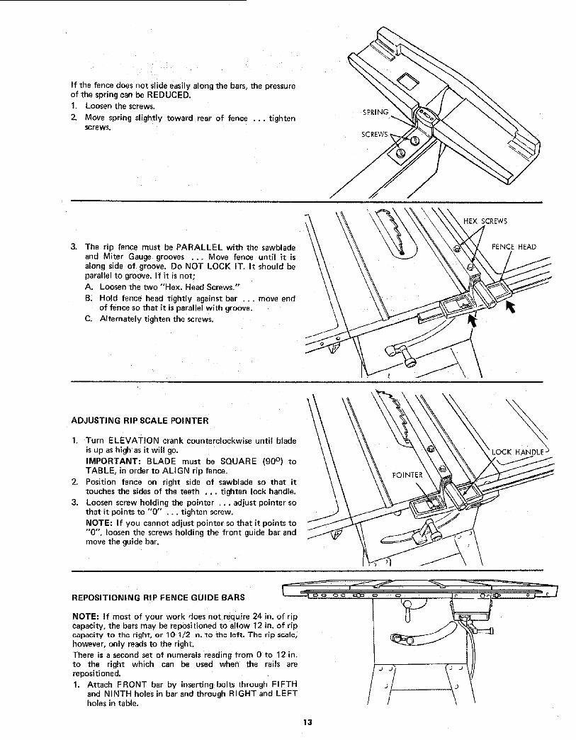
4. Operate the tilt-lock handle (COUNTERCLOCKWISE)to loosen the tilt clamp screw.
5. NOTE; Handle is spring loaded for engagement withscrew head -- must be pushed inward for disengagementwhenever necessary to obtain a new grip on screw head.
i • I
CLAMPSCREW
LOCK HANDLE
•1///
6. Rotate tilt crank CLOCKWISE a few turns to tilt blade.Now rotate crank COUNTERCLOCKWISE until itstops. Blade should now be square with table andpointer should point to "'0".
/I
TILT CRA NK
If t
If blade IS SQUARE to table;
A. Check pointer
If POINTER DOES NOT point to the "O'" mark on thebevel scale;
B. Loosen screw and adjust pointer ... using mediumscrewdriver.
I, /,g |
I ,./POINTERAT
"0" POSITION
If blade is NOT SQUARE to table ... the 90 ° LIMITSTOP must be ADJUSTED.
1. Using a medium size screwdriver, loosen BOTHsetscrews in 90 ° STOP COLLAR.
NOTE: If you can't reach the setscrews, turn the TILTCRANK slightly.
2. ROTATE the STOP COLLAR moving it all the way tothe end of TILT SCREW. (to the right)
3. TILT blade RIGHT or LEFT . .. checking with yoursquare until blade is square to table.
4. ROTATE STOP COLLAR moving it to the right until itstops . .. TIGHTEN the setscrews.
5. Check POINTER. If it DOES NOT point to the "'O "°mark on the bevel scale ... loosen screw and adjust
pointer.
45 ° STOP COLLAR
TILTCRANK
/
STOP COLLAR
31

45° POSITION
TILT blade to LEFT as far as it will go. It will stop when"_
the PIVOT NUT is against the 45 ° STOP COLLAR ... andthe pointer SHOULD POINT to the "45" mark on thebevel scale.
If POINTER DOES NOT POINT to the "'45" mark ... the45° STOP COLLAR must be ADJUSTED.
I. Insert a medium screwdriver through the slot and
loosen BOTH setscrews in 45 ° STOP COLLAR. _ \NOTE: If you can't reach the setscrews, turn the TILT \crank slightly. \ _-_
2. Reach inside the saw from REAR ... ROTATE theSTOP COLLAR a few turns moving it toward the TILTCRANK (to the left).
3. TILT blade until POINTER points to "45" mark.
4. ROTATE STOP COLLAR moving it to the right until itstops... TIGHTEN the setsCrews.
TI LT MECHANISM
The crank should turn freely without binding. The turningaction can be adjusted by tightening or loosening the screwsin the bearing retainer.
NOTE: When adjusting the screws on the tilt crank, holdthe nut inside usinga 3/8 in, wrench.
1I
TILT CRANK
fADJUSTTHESE
SCREWS
/
MAINTENANCE
WARNING: FOR YOUR OWN SAFETY, TURN SWITCH"OFF" AND REMOVE PLUG FROM POWER SOURCEOUTLET BEFORE MAINTAINING OR LUBRICATINGYOUR SAW.
Do not allow sawdust to accumulate inside the saw.
Frequently blow out any dust that may accumulate insidethe saw eebinet _nd the motor.
Frequently clean your cutting tools with Craftsman Gumand Pitch Remover.
A coat of automobile-type wax applied to the table willhelp to keep the surface clean and allow workpieces to slidemore freely. Treat unplated and unpainted steel parts andsurfaceswith Sears "Stop Rust.'"
f the power cord is worn or cut, or damaged in any way,have it replaced immediately.
Make sure the teeth of the ANTIKICKBACK pawls arealways sharp. To sharpen:
1. Remove blade guard.
2. Rotate pawl towaro rear of spreader so that teeth areabove top of spreader.
3. Hold spreader with left I" and and place pawl over cornerof workbench.
4. Using a sma round file (Smooth Cut) sharpen theteeth.
32

LUBRICATION
The following parts should be oiled occasionally with SAENo. 20 or No. 30 engine oil.
1. Tilt screw threads and pivot nut, (First Clean withCraftsman Gum & Pitch Remover,)
2. Elevation screw threads and pivot nut. (First Clean withCraftsman Gum & Pitch Remover,)
3. Cradle bearing points.
4. Bearing points in guard assembly, miter gauge and ripfence.
GUARD '_
MITER GUAGE
BEARING POINTS
/
C
°t
RECOMMENDED ACCESSORIESIN CANADA, SEE YOUR LOCAL SIMPSONS-SEARS STORE
OR CATALOG FOR ACCESSORY SELECTION AND NUMBERS.
ITEM CAT. NO.
Steel Legs ............................... 9-22235Steel Stand .............................. 9-22214
Tool Bench ............................... 9-1071
Retractable Caster Set for Steel Legs .......... 9-22209Retractable Caster Set for Steel Stand ......... 9-22201
Solid Table Extension ...................... 9-29957
_Adjustable Table Extension ................. 9-2178
7 In. Molding Head Set ...................... 9-3217
7 In. Molding Head Set ...................... 9-3218
7 In. Molding Head ......................... 9-3214
Molding/Dado Insert for 7 In,
Dia. Molding or Dado Head ................. 9-29994
ITEM CAT. NO.
Work Light ............................... 9-2480
Work Light ............................... 9-2481
7 In. Dia. Adjustable Dado Head .............. 9-3263
7 In. Dia. Dado Head ....................... 9-3257
Blade Stabilizers ........................... 9-4952
Sanding Wheel ........................... 9-22723
Miter-Gauge Stop Rods ..................... 9-29924
Miter-Gauge Hold-Down Clamp .............. 9-29928
Hold-Down Set ............................ 9-3230
Taper Jig ................................. 9-3233
Universal Jig .............................. 9-3231Power Tool Know How Handbooks
Table Saw .............................. 9.2918
*CAN ONLY BE ATTACHED TO SAW TABLE NOT TO
TABLE EXTENSIONS.
33

TROUBLE SHOOTINGWARNING: FOR YOUR OWN SAFETY, TURN: SWITCH "OFF" AND ALWAYS REMOVE PLUG FROM POWER SOURCEOUTLET BEFORE TROUBLESHOOTING.
TROUBLE SHOOTING -- GENERAL
TROUBLE
Excessive vibration.
Cannot make square
Cut when crosscutting.
Cut binds, burns or
stalls motor when
ripping.
Cut not true at 90 °
or 45 ° positions.
Tilt crank and elevating
crank turn hard.
PROBABLE CAUSE
1. Blade out of balance,
1. Miter gauge not adjusted
properly.
1. Dull blade with impropertooth set,
2. Blade is Heeling•
3. Warped board.
4, Rip fence not parallelto blade,
5. Spreader out ofalignment
1. Stop collars not properly
adjusted.
1. Sawdust on threads of tilt
screw or elevating screw.
2. Bearing retainers
to tight.
' REMEDY
1. Discard Blade and use a different blade.
1. See "Adjustments" section "Miter Gauge."
1. Sharpen or replace blade.
2. See "Adjustments" section, "Heeling Adjustment,.."
3. Make sure concave or hollow side is facing
"down," feed slowly.
4. See "Assembly" section, "Aligning Rip Fence"
5. See "Assembly" section, "Installing
Blade Guard,'"
1, See "Adjustments" section, "Blade Tilt, or
"Squareness of Blade to Table."1. See "Maintenance and Lubrication" section•
2. See "Maintenance" section
"Tilt and Elevation Mechamsm.
TROUBLE SHOOTING -- MOTOR
TROUBLE
Excessive noise.
Motor fails to develop
full power. (Power
output of motor decreases
rapidly with decrease in
voltage at motor terminals.
For example, a reduction
of 10% in voltage causesa reduction of 19% in
maximum power outputof which the motor is
capable, while a reduction
of 20% in voltage causesa reduction of 36% in
maximum power output.)
NOTE: Motors used on wood-working tools are particularlysusceptible to the accumulation of sawdust and wood chipsand should be blown out or "vacuumed" frequently toprevent interference with normal motor ventilation,
I PROBABLE CAUSE
1. Motor.
1. Circuit overloaded with
lights, appliances andother motors.
2. Undersize wires or circuit
too long.
3. General overloading of
power company
facilities. (In some
sections of the
country, demand for
electrical power may
exceed the capacity
of existing generating
and distribution systems.)
4. Incorrect fusesor circuit
breakers in power line.
REMEDY
1. Have motor checked by qualified service
technician. Repair service is available at
your nearest Sears store.1. Do not use other appliances or motors on
same circuit when using the saw.
2. Increase wire sizes, or reduce length of wiring.
See "Motor Specification and Electrical
Requirements" section.
3, Request a voltage check from the power company,
4. Install correct fuses or circuit breakers.
34

TROUBLE SHOOTING -- MOTOR (Continued)
TROUBLE
Motor starts slowly
or fails to come up
to full speed.
Motor overheats. 1.
2.
Starting switch in 1.
motor will not
operate.
2.
3.
Motor stalls 1.
(resulting in blown
fuses or tripped 2.
circu it breakers).
Frequent opening of
fuses or circuit
breakers.
PROBABLE CAUSE
1. Low voltage will not
trip relay.
2. Windings burned out
or open.
3. Starting relay not
operating.Motor overloaded.
Improper cooling. (Air
circulation restricted
through motor due to
sawdust, accumulating
inside of saw).
Burned switch contacts
(due to extended
hold-in periods caused
by low line voltage, etc.)
Shorted capacitor
(when equipped)Loose or broken
connections.
Starting switch not
operating.
Voltage too low to permit
motor to reach operating
speed.
3. Fusesor circuit breakers
do not have sufficient
capacity.1. Motor overloaded,
2. Fusesor circuit breakers
do not have sufficient
capacity.
3. Starting switch not
operating (motor does
not reach speed).
REMEDY
1, Request voltage check from the power company.
2. Have motor repaired or replaced.
3. Have relay replaced,
1. Feed work slower into blade,
2. Clean out sawdust to provide normal air
circulation through motor.
See "Maintenance and Lubrication" section.
1. Have switch replaced and request a voltage check
from the power company,
2. Test capacitor and replace if defective.
3. Have wiring checked and repaired.
1. Have switch replaced,
2, Request voltage check from the power company.
3. Install proper size fuses or circuit breakers.
1. Feed work slower into blade.
2. Install proper size fusesor circuit breakers.
3. Have switch replaced.
35

<_I-,- .."!"=3O o
oOO3_,--O3
z _.
14. "¢P<_i'v- o3o_.n- 0")o_It.
u'Jz.,=1 ,-J
=::O
O-
o4
!
REPAIR PARTS
!
/t/
P
M.,
36
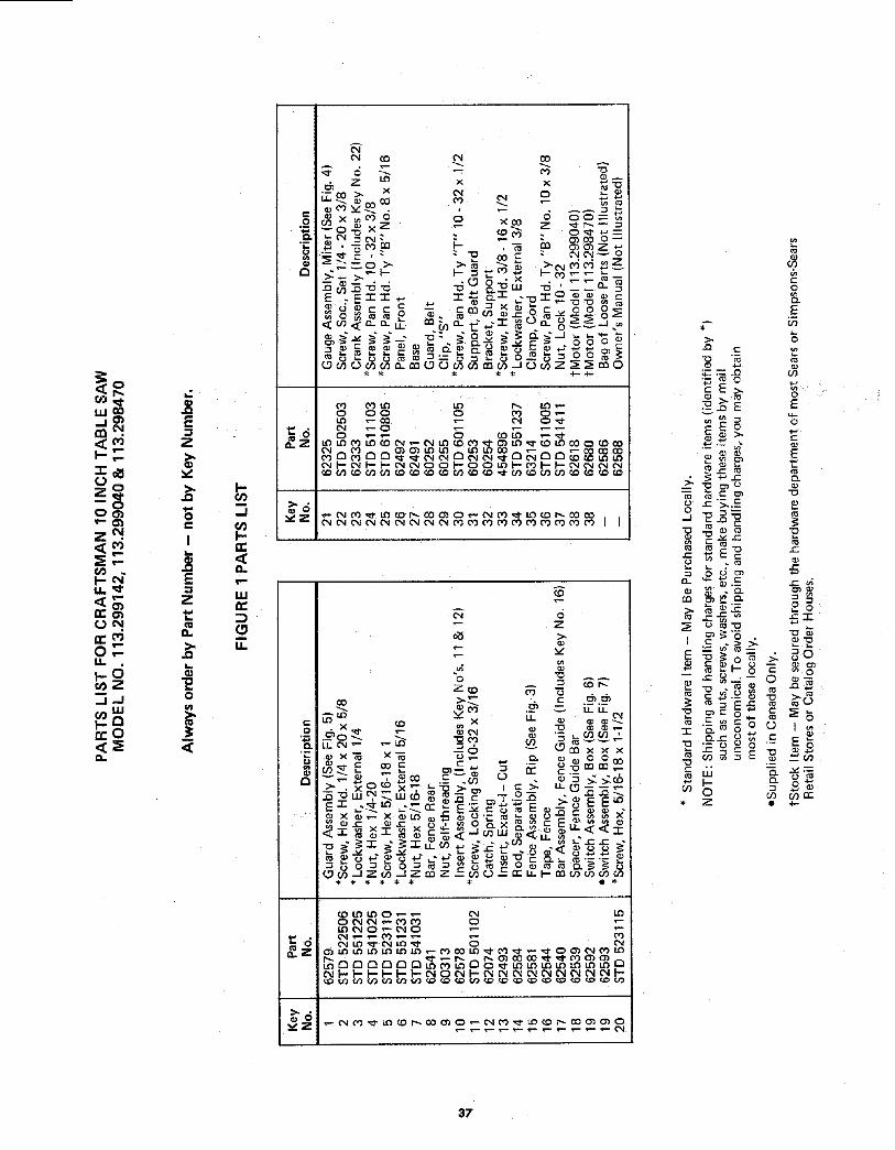
_o
..jmmN,
0
_zo.o0_
z N.
<_
OT-u.
.j.J_Lu
,_-O
,,L
Ez
v
oe,
I
E
Z4,a&.
o
,<
I-
--I
i-n-,<
T"
ILl
(.9,'T
8
r,
, _rn _ , _ rn _Z. _
-- _-- (DO " _ _'-"
_ C C -- CO0 0 C 0 0O _ ',n _ ..c _
_6
0
_o
o
aZ
>,c
'- _ 0
EE>
_--
NI---0Z
(9.
o
E
cO
oE
E
t'_
o
_ _ _o
37

kl.l_
z
I,..-_
o_
._1 ,-I
a.
o
\
\
\
38

0
io 0
_" _ _.,--_x _ _ _
"o w .-oo_o. =o_'o_"ooc< o_-_ ° .=_'J'J'<_w_" o*_ 1::: '-- "" '-- _ -- 0 ,-- 0 0 0 0 _0
o_ o o _ _
]
{3
,.L
X
0
eX X_ ¢9"0 _" (X)
x oooo_ x:: x_
{D J= '--0 -_'OLU _'_ C *-- 009 0 _ C "_" -_LU C _.r_ C XE _ :]: ::E " _m-- 0 C "" 0 .C ::E .
____ -_ ._o _._-- _____ _ __Q.O-O_ w m c m _= _ _ u_ c C c _ c _
w
.J
"o
E
(o"i-
"o
o9
E
E__o 0
-o 0
o(J
0
o
(J
_J&o00
39

PARTS LIST FOR CRAFTSMAN 10 INCH TABLE SAWMODEL NO. 113.299142, 113,299040 & 113.298470
1 2
3 4
tI
FIGURE 3 -- 62581 FENCE ASSEMBLY
KeyNo.
123456789
10111213141516
PartNo. Description
62581 Fence Assembly, Rip62524 HandleSTD 551031 *Washer, 21/64 I.D.
62534 Indicator, Fence "T" 4 40 x 3/1660049 *Screw, Pan Hd. Type -62527 Head, Fence423350 Screw, Sems 3/8-16 x 1/262582 Channel, FenceSTD 611005 *Screw, Pan Hd. Type "A" 10-32 x 5/862528 Spring, Fence Lock62529 Lock, Rear Fence62531 ' Roller, Rear Fence62583 ' Rod, Fence Lock62533 Spring, Head AlignmentSTD 551210 *Lockwasher, External No. 1062532 Pad, AliqnmentSTD 600805 *Screw, Pan Hd. Type "T" 8-32 x 1/2
* Standard Hardware Item - May be Purchased Locally.
4O

PARTS LIST FOR CRAFTSMAN 10 INCH TABLE SAWMODEL NO. 113.299142, 113.299040 & 113.298470
I
13!
T--4
6
FIGURE 4 - 62325 MITER GUAGE ASSEMBLY
KeyNo. Description
PartNo.
- 623251 625242 STD 5510313 378934 STD 6008035 1356 378957 378968 9417295
62230
10 STD 54123111 6222512 6238313 STD 502503
tGauge Assembly, MiterHandle, Miter Gauge
*Washer, Plain, 21/64 x 1 x 1/16"Gauge, Miter
*Screw, Pan Hd. 8-32 x 5/16"IndicatorBlock, Miter Gauge IndicatorPin, Miter Gauge Stop
*Screw, Pan Hd., w/Lockwasher,8-32 x 5/8".Rod Assembly, Miter Gauge,Consisting of Items 10, 11, 12
*Nut, Hex., 5/16-18 x 1/2x 3/16"Stud, ClampStud, PivotScrew, Set1/4-20 x 3/8"
1
11 1 6
/
J 12
FIGURE 5 - 62579 GUARD ASSEMBLY
Key PartNo. No. Description
625791 602972 623913 623954 62389
62390STD 5510257 621368 623969 62580
10 6241011 STD 57181012 62134
Guard Assembly, SawNut, PushPin 1/4 x 1-1/2"Support, GuardGuard, SawPin, I/4 x 1-3/4"
*Washer, 17/64 x 5/8 x 1/16"Spacer, PawlPawlSpreader, Assembly BladePin, 1/4 x 1"
*Pin, Roll, 3/16 x 15/16"Spring, Pawl
* Standard Hardware Item May be Purchased Locally.
t Stock Item -- May be secured through the Hardware Departments of mostSears or Simpsons-Sears Retail Stores or Catalog Order Houses.
41

"\
42

PARTS LIST FOR CRAFTSMAN 10 INCH TABLE SAWMODEL NO. 113.299142, 113.299040 & 113.298470
1 2
I
!/
j9
6 5 4
12 11
2
FIGURE 8 -- LEGS FOR MODEL 113.299040AND 113.298470 ONLY
NOT SUPPLIED IN CANADA
°YINo.
1
2
3
4
5
6
7
8
Part
No. Description
60314
62552
62554
STD 551225
STD 541025
62553
120238803835
Screw, Serrated Truss Hd. 1/4-20 x 5/8
Leg
Stiffener, Side
*Lockwasher, Ext. 1/4
*Nut, Hex 1/4-20
Stiffener, End
Nut, Hex 1/2-13
Foot, Leveling
HARDWARE FOR ATTACHING LEGS TO SAW.
9 STD 523112 *Screw, Hex Hd. 5/16-18 x 1-1/4
10 STD 551031 Washer, 11/32 I.D.11 STD 551131 *Lockwasher, Ext. 5/16
12 I STD 541031 *Nut, Hex 5/16-18
/ 62591 ieBag of Loose Parts not illustrated)
1
FIGURE 9- TABLE EXTENSION FOR MODEL113.299040 AND 113.298470 ONLY
Key
No.
1
2
3
4
567
Part
No.
62589
60323
62590
62549
62548
Description
tExtension Assembly, Complete
Screw, Serrated Truss Hd.,
1/4-20 x 1"
Extension
Bracket, Corner Support No. 2
Bracket, Corner Support No. 1
STD 541025 "Nut, Hex 1/4-20
STD 551225 i" Lockwasher, Ext. 1/4
62550 Bracket, Corner Stiffener
HARDWARE FOR ATTACHING EXTENSION TO TABLE
8 STD 523112=*Screw, Hex Hd. 5/16-18 x 1-1/4
9 STD 551131 *Lockwasher, Ext. 5/16
10 STD 541031 *Nut, Hex 5/16-18
62591 eBag of Loose Parts (not illustrated)
* Standard Hardware terns-- May be Purchased Locally.
• Bag contains all Loose Parts for both Legs and Extensions.
t Stock Item - May be secured through the Hardware
Departments of most Sears or Simpsons-Searsretail stores or catalog order house.
43

Sears
ownersmanual
SERVICE
MODEL NO.113.299142
SAW ON LY
113.299040SAW WITH LEGS
TWO TABLE EXTENSIONSAND MOTOR
113.298470SAW WITH LEGS
ONE TABLE EXTENSIONAND MOTOR
HOW TO ORDER
REPAIR PARTS
i-i ....
10 INCH TABLE SAW
Now that you have purchased your 10-inch table saw shouldaneed ever exist for repair parts or service, simply contact anySears Service Center and most Sears, Roebuck and Co. stores.Be sure to provide all pertinent facts when you call or visit.
The model number of your 10-inch tab e saw will-be found on aplate attached to your saw, at the left-hand side :of the base.
WHEN ORDERING REPAIR PARTS, ALWAYS GIVE THEFOLLOW NG INFORMATION:
PART NUMBER
MODEL NUMBER113.299142,113.299040or113,298470
PART DESCRIPTION
NAME OF ITEM10-INCH TABLE SAW
All parts listed may be ordered from any Sears Service Centerand most Sears Stores. If the parts y0u_i_eed are not stockedlocally, your order will be electronically transm tted to a SearsRepair Parts Distribution Center for f_ancl]ing.
Sold by SEARS, ROEBUCK AND CO., Chicago, IL. 60684 U.S.A.
Part No. 62588 Form No. SP4149-10 Printed in U.S.A. 9P _"