SeaPerch ROV Construction Manual - NORTHWEST PROGRAM ... ROV... · SeaPerch ROV Construction Manual...
110
Version 2010-04NW SeaPerch Remotely Operated Vehicle (ROV) Construction Manual Standard and Selected Optional Assembly Procedures August 2010 The SeaPerch educational program was created by Harry Bohm and Vickie Jensen and published in their 1997 book " Build Your Own Underwater Robot and Other Wet Projects." The initial curriculum was developed by the Massachusetts Institute of Technology, and this version of the SeaPerch Construction Manual was provided under the Office of Naval Research National Naval Responsibility for Naval Engineering (NNRNE) Outreach initiative.
Transcript of SeaPerch ROV Construction Manual - NORTHWEST PROGRAM ... ROV... · SeaPerch ROV Construction Manual...

Version 2010-04NW
SeaPerch
Remotely Operated Vehicle (ROV)
Construction Manual
Standard and Selected Optional
Assembly Procedures
August 2010
The SeaPerch educational program was created by Harry Bohm and Vickie Jensen and published in their 1997 book "Build Your Own Underwater Robot and Other Wet Projects." The initial curriculum was developed by the Massachusetts Institute of Technology, and this version of the SeaPerch Construction Manual was provided under the Office of Naval Research National Naval Responsibility for Naval Engineering (NNRNE) Outreach initiative.


SeaPerch ROV Construction Manual – Version 2010-04NW
I
Table of Contents
Introduction ------------------------------------------------------------------------------------------ I-1
SeaPerch ROV Program Overview ------------------------------------------------------------ I-1
What is SeaPerch? ---------------------------------------------------------------------------- I-1
Program History --------------------------------------------------------------------------------- I-2
Original SeaPerch ROV Manual Development ----------------------------------------- I-2
Updated Information in this Manual ------------------------------------------------------------ I-2
Revised Standard SeaPerch Assembly Instructions ---------------------------------- I-2
Expanded Testing and Operating Information ------------------------------------------ I-3
Added Appendix Containing Troubleshooting Hints ----------------------------------- I-3
Added Supplement for Construction Options and Enhancements ---------------- 1-3
The SeaPerch Assembly Process -------------------------------------------------------------- I-5
Three Individual Building Units ------------------------------------------------------------- I-5
Recording Progress ---------------------------------------------------------------------------- I-5
Testing and Adjustments --------------------------------------------------------------------- I-5
Tools and Materials ---------------------------------------------------------------------------- 1-6
Manual Printing Considerations ------------------------------------------------------------- 1.6
Safety Overview -------------------------------------------------------------------------------- S-1
Protective Eyewear ------------------------------------------------------------------------------- S-1
Materials Handling Safety ---------------------------------------------------------------------- S-2
Safety While Using Hand Tools --------------------------------------------------------------- S-2
Safety While Drilling ------------------------------------------------------------------------------ S-3
Safety While Soldering -------------------------------------------------------------------------- S-4
Safety While Potting Motors for Thrusters -------------------------------------------------- S-4
Safety With Electricity and Batteries --------------------------------------------------------- S-5

OPTIONAL TABLE OF CONTENTS II – PVC TUBE FLOAT OPTION SeaPerch ROV Construction Manual – Version 2010-04NW
II
Unit 1 – Assembly of Subsystem One – The Vehicle Frame ----- 1.0-1
Tools and Materials Needed ------------------------------------------------------------------ 1.0-2
Time Needed to Complete Unit 1 ------------------------------------------------------------ 1.0-2
Procedure 1.1 – Cut the Frame Parts ------------------------------------------------------ 1.1-1
Procedure 1.2 – Drill the Drain Holes ------------------------------------------------------- 1.2-1
Procedure 1.3 – Assemble the Vehicle Frame ------------------------------------------- 1.3-1
Procedure1.4A – Assemble the PVC Tube Floats ------------------------------------- 1.4A-1
Procedure1.4B – Install the Floats and Tighten the Frame -------------------------- 1.4B-1
Procedure 1.5 – Attach the Thruster Mounts --------------------------------------------- 1.5-1
Procedure 1.6 – Attach the Payload Net --------------------------------------------------- 1.6-1
Unit 2 – Assembly of Subsystem Two – The Thrusters ------------- 2.0-1
Tools and Materials Needed ------------------------------------------------------------------ 2.0-2
Time Needed to Complete Unit 2 ------------------------------------------------------------- 2.0-2
Procedure 2.1 – Build a Motor Potting Holder (If Not Provided) ---------------------- 2.1-1
Procedure 2.2 – Test the Motors and Mark their Terminals' Polarity --------------- 2.2-1
Procedure 2.3 – Seal the Motors So That Wax Cannot Get Inside ----------------- 2.3-1
Procedure 2.4 – Drill Holes in the Thruster Housings --------------------------------- 2.4-1
Tips on Soldering – Safety and Techniques ---------------------------------------------- 2.5-1
Procedure 2.5 – Connect the Tether Cable Wires to the Motors -------------------- 2.5-2
Tips on Wax Melting – Safety and Techniques ------------------------------------------ 2.6-1
Procedure 2.6 – Pot (Waterproof) the Motors with Wax ------------------------------- 2.6-2
Procedure 2.7 – Mount the Propellers onto the Motors’ Shafts ---------------------- 2.7-1
Procedure 2.8 – Mount the Thrusters onto the Vehicle Frame --------------------- 2.8-1
Procedure 2.9 – Waterproof and Mount the Tether Cable ---------------------------- 2.9-1

SeaPerch ROV Construction Manual – Version 2010-04NW
III
Unit 3 – Assembly of Subsystem Three – The Control Box ------- 3.0-1
Tools and Materials Needed ------------------------------------------------------------------ 3.0-2
Time Needed to Complete Unit 3 ------------------------------------------------------------ 3.0-2
SeaPerch ROV Electrical Circuit Diagram ------------------------------------------------ 3.0-3
Procedure 3.1 – Gather the Parts for the Control Box Assembly ------------------- 3.1-1
Procedure 3.2 – Prepare the Control Box ------------------------------------------------- 3.2-1
Procedure 3.3 – Assemble the Power Cord ---------------------------------------------- 3.3-1
Procedure 3.4 – Wire the Vertical Thruster Control Switch --------------------------- 3.4-1
Procedure 3.5 – Wire the Horizontal Thruster Control Switches -------------------- 3.5-1
Procedure 3.6 – Finish the Control Box ---------------------------------------------------- 3.6-1
Testing and Ballasting the ROV
Time Needed to Complete Testing and Ballasting of the ROV ------------------------ T-1
Initial Electrical Testing --------------------------------------------------------------------------- T-1
Ballasting and Trimming the ROV -------------------------------------------------------------- T-2
Initial In-Water Testing in the Classroom, Lab, or Pool ----------------------------------- T-4
Using the SeaPerch ROV
Safety Precautions --------------------------------------------------------------------------------- U-1
Environments Suitable for Using a SeaPerch ROV --------------------------------------- U-1
Driving the SeaPerch ROV ----------------------------------------------------------------------- U-2
Post-Run Cleaning and Maintenance of the ROV System ------------------------------ U-3
Appendix A – Troubleshooting Your SeaPerch ROV
Things to Try Before Re-Wiring the ROV or Changing ROV Parts ------------------- A-1
Solving Directional Control Problems ---------------------------------------------------- A-1
Solving Thruster Operational Problems ------------------------------------------------- A-2


SeaPerch ROV Construction Manual – Version 2010-04NW
I-1
Introduction
SeaPerch ROV Program Overview
What is SeaPerch?
SeaPerch is an educational tool – a fun, hands-on learning activity and a curriculum that can be enjoyed by a wide range of students, ranging from late elementary school through high school and even introductory college programs. The curriculum is designed to meet many of the national learning standards identified by the United States Government. Often applied at the middle school (or junior high school) level, SeaPerch is challenging, creative, and gets kids excited about science and technology. The SeaPerch program is sponsored through the National Naval Responsibility for Naval Engineering (NNRNE) Outreach effort, with the goal of helping to inspire the next generation of naval architects and marine, ocean, and naval engineers.
A SeaPerch is an underwater robot known as a “remotely operated vehicle,” or “ROV.” Students learn best by doing, and during the SeaPerch project, they will completely assemble an inexpensive, yet functional ROV, test it, and then operate it underwater. The experience will enable them to explore science and technology both in the classroom and in a pool, or, for some, in natural marine environments. The ROVs are built from kits comprised of low-cost, easily-obtained components. Students often work in small teams to assemble their vehicles, usually over a period of several weeks. From the classroom activities during SeaPerch construction through in-water application of the ROV, they will have opportunities to learn about various subjects including mathematics, robotics, biology, oceanography, physics, and history, as well as valuable problem solving and teamwork skills.
The SeaPerch program is structured to provide free training to help teachers more effectively lead students through the variety of interdisciplinary activities involved. Within one project, a number of concepts required for their grade level can be efficiently addressed, with the further benefit of exposing the students to additional concepts that may not otherwise be easily covered with their standard curriculum. Mentors from government and industry are often available to support and reinforce the lessons as well as to assist with the SeaPerch construction and application activities in the classroom.

SeaPerch ROV Construction Manual – Version 2010-04NW
I-2
Program History
The SeaPerch Remotely Operated Vehicle (ROV) educational program was inspired by the 1997 book, Build Your Own Underwater Robot and Other Wet Projects (ISBN 0-9681610-6), by Harry Bohm and Vickie Jensen. In 1997, Dr. Tom Consi introduced SeaPerch to the Ocean Engineering program at the Massachusetts Institute of Technology (MIT), in order to interest more students in majoring in Ocean Engineering. Realizing the potential of SeaPerch to reach younger students, the MIT Sea Grant (MITSG) College Program created the SeaPerch initiative in 2003, sponsored by the Office of Naval Research. Dr. Chryssostomos Chryssostomidis, MITSG Director, and Brandy Wilbur, Educational Coordinator, were responsible for the effort at MIT Sea Grant. In late 2007, the Office of Naval Research (ONR) tasked the Society of Naval Architects and Marine Engineers (SNAME) to research ways to expand and enhance the SeaPerch initiative as part of the ONR National Naval Responsibility for Naval Engineering Outreach effort.
Original SeaPerch ROV Manual Development
The SeaPerch Construction Manual was originally developed by MITSG, which modified the instructions for building a SeaPerch from those found in Build Your Own Underwater Robot and Other Wet Projects so that the ROV would be simpler and cheaper to build in the classroom. MITSG created a three-unit manual with detailed, step-by-step instructions and a complete list of needed components and tools. The MITSG SeaPerch manual has been revised several times in recent years as new vehicle components or updated assembly methods were implemented for the program.
Updated Information in This Version of the SeaPerch Manual
Revised Standard SeaPerch Assembly Instructions
This 2010 manual revision builds upon the extensive work of the MITSG developers by utilizing the experience gained through years of SeaPerch program use by educators around the country, incorporating the latest recommended construction techniques, and providing additional information to help teachers and students build and use SeaPerch ROVs. While much of this revision’s technical content is aligned with the instructions found in previous versions, its revised graphics and content adjustments are designed to provide additional detail for the more complex construction techniques and to facilitate high-quality reproduction in either monochrome or color. The addition of sign-off boxes for the construction steps will better enable students, teachers, and classroom volunteers to monitor completion progress.

SeaPerch ROV Construction Manual – Version 2010-04NW
I-3
The following summarizes the significant changes from previous manuals.
Consolidation of safety information and added program background information at the front of the manual, to better enable a discussion of all safety aspects of the project during a class session early in the project.
Revised graphics to clarify electrical wiring and show recommended soldering techniques.
Minor changes to some recommended construction methods to avoid occasional assembly difficulties that have been identified through experience in a variety of classroom programs.
Revised numbering for major assembly procedures and for the document’s pages to enable easy substitution of optional or enhancement procedures for standard SeaPerch procedures.
Addition of separate manual sections for initial testing and ballasting the ROV as well as for use and cleaning of the vehicle.
Addition of an appendix with troubleshooting hints.
Addition of a separate construction manual supplement document offering a variety of proven construction options and enhancements.
Expanded Testing and Operating Information
Because proper ballasting and pre-deployment testing are essential for successful in-water operation of SeaPerch ROVs, the instructions and supplemental information for these activities are now in a separate, expanded section of this manual entitled “Testing and Ballasting the ROV.”
In addition, operational recommendations, some helpful hints, application ideas, and post-run vehicle cleaning instructions have been placed in a new, final, manual section entitled “Using the SeaPerch ROV.”
Added Appendix Containing Troubleshooting Hints
When the initial ROV testing process identifies a problem, it is best for students to be allowed to try to solve it. However, when help is needed, and before taking drastic steps to change ROV parts or re-wire a circuit, ROV builders should refer to Appendix A, “Troubleshooting Your SeaPerch ROV,” which suggests options for solutions to common problems. This appendix is not necessarily intended to be included in the student copies of the construction manual; rather, it is provided for the teacher’s reference and for classroom use at the teacher’s option.
Added Supplement for Construction Options and Enhancements
Occasional challenges in obtaining recommended components, special technical requirements, and local budget constraints have inspired creativity and resourcefulness among SeaPerch program implementers, many of whom have found it useful or necessary to identify alternatives for various aspects of their ROVs’ construction. In order to provide such needed flexibility while still

SeaPerch ROV Construction Manual – Version 2010-04NW
I-4
maintaining a standardized set of assembly instructions that can be fielded nationwide, the manual’s format has been updated to enable easy substitution of proven and approved procedures to implement construction "options," in place of corresponding standard procedures, and addition of new procedures for construction “enhancements” to add capabilities to the ROV. These optional and enhancement procedures are contained in a separate document, “SeaPerch ROV Construction Manual Supplement – Options and Enhancements – Version 2010-01,” which may be downloaded from the SeaPerch website. It contains a number of alternate and added procedures that have been found to be useful to improve ROV performance, simplify the build process, and/or lower costs.
This "Northwest Program Options" version of the standard Version 2010-01 manual has been customized to meet the needs of Pacific Northwest and Alaska schools. It has been assembled with alternate procedures from the supplement for the following SeaPerch construction options and enhancements already substituted for the corresponding standard SeaPerch procedures.
Fabrication and Use of Low-Cost PVC Tube Floats as Alternate Floatation o Instead of Foam Floats and the H-Columns on which they are Mounted
o Improves ROV Operation in Deep Water & Enables Easy Front-to-Back Trim Adjustment
Use of Front PVC Tees as Attachment Points and for Fast Draining o Instead of PVC Elbows
Use of a Toggle Switch for the Vertical Thruster o Instead of Two, More-Expensive, Pushbutton Switches
Use of Alternate Motor 1 with Film Canisters for Thruster Housings o Smaller, Less-Expensive Motors – Instead of Standard SeaPerch Motors
o Use of Film Canisters for the Thruster Housings – Instead of Larger, Costly, Plastic Vials
o Simplified Motor Insertion for the Wax-Potting Procedure – Faster, Easier, & Less Rework
Use of a No-Adhesive Mounting Method for Reusable, Standard Propellers o Instead of Costly Shaft Couplers with Nuts and Two-Part Adhesive
o Propellers Can Be Reused Many Times (Avoided Future Cost)
Use of Quick-Disconnect Battery-Terminal Connectors and an Alternate Motor Test o Instead of More-Expensive Alligator Clips
Addition of a Payload Capture Net and a Front Payload Net Stiffener o To Improve the ROV’s Ability to Pick Up Bottom Objects
More options and enhancements will likely be developed from time to time as clever students and their teachers continue to invent and demonstrate new ways to build SeaPerch ROVs. By using the supplement approach and the new page numbering scheme, future new procedures can easily be added to the supplement document and then to individual classroom manuals when needed, without impacting the content of the standard build manual.
Future new procedures will need to go through a short demonstration and approval process before being added to the master manual supplement document that is maintained at the SeaPerch website for downloading as needed.

SeaPerch ROV Construction Manual – Version 2010-04NW
I-5
The SeaPerch Assembly Process
Three Individual Building Units
The manual contains three building units, for the frame, the thrusters, and the control box. They may be used as a single manual, as assembled here, or they can be removed from this manual and placed into the SeaPerch classroom integration manual at the separate locations indicated therein. In either case, the three unit manuals should always be used in order.
Unit 1 is a good confidence-builder for the students who have had little experience working with tools, and it gets the project going quickly. They will measure, cut, and drill pipe and fittings and then assemble the parts with quick results, as the work in Unit 1 provides a recognizable ROV after just a few class periods.
Unit 2 then introduces basic wiring and soldering skills through the work with the motors for the thrusters. These skills are important for them to have when building the control box in Unit 3.
Finally, Unit 3 involves the students in more advanced wiring and soldering activities and provides an opportunity for them to work with a variety of tools and components used in electrical technologies.
Recording Progress
The checklist-style boxes next to each numbered step in the manual are intended for the students to write their initials confirming proper completion of each step as they progress through the project. Multiple sign-off boxes are provided whenever a step needs to be repeated, such as during assembly of the three thrusters. Keeping track in this way is important to avoid accidentally skipping steps, but it also greatly helps the teacher and classroom volunteers (as well as other team members, if working in teams), to know how far the student or team has progressed in the building process.
Testing and Adjustments
The last steps in the SeaPerch ROV construction process are to conduct some basic electrical tests, prior to connecting the battery, and performing some simple vehicle checks and adjustments prior to its first operational use. The initial testing in the classroom or lab should help in finding any lingering wiring or thruster-related issues, and the checks recommended before operational use should help to ensure a successful operational experience for all students.

SeaPerch ROV Construction Manual – Version 2010-04NW
I-6
Tools and Materials
Each procedure in this manual identifies the needed components and tools only generically, rather than giving specific descriptions or specifications for each item. Detailed parts, tools, and materials lists are maintained as separate documents for use in procuring the items needed to build the ROVs. This approach allows these assembly instructions to remain applicable even when the specifics of individual components change, such as when a slightly different “12 Volt DC Motor” is used or when a similar component must be substituted due to availability or cost issues.
SeaPerch ROVs are often built by a team of two or three students. For efficiency during the build process, each team should have its own set of basic tools, including a screwdriver, flush-type wire cutter, needle-nose pliers, wire stripper, and soldering iron. Tools such as standard pliers, cable jacket strippers, pipe cutters, drills, and others that are not used on a daily basis can be easily shared among a number of teams. A key aspect of planning for classroom tools is to arrange to obtain enough to ensure that students do not need to stop long during the build process to wait for availability of needed tools.
Manual Printing Considerations
Please note that this manual is set up for double-sided (duplex) printing, with a number of extra blank pages inserted to force all procedures to start on the front side of a sheet. Besides some savings in paper, this approach allows any individual procedure from the supplement (or a future updated version of a standard procedure) to be swapped into the manual as needed without affecting an adjacent procedure or the overall page numbering.
The intent, in providing the manual in double-sided format, is to enable easy creation of double-sided student manuals, either by directly printing them on a duplex printer or by printing a single-sided or double-sided master document to use to reproduce the student manuals with a two-sided photocopier.
If single-sided reproduction is desired, simply print a copy of the manual on a single-sided printer, pull out the blank sheets, and then reproduce the single-sided student manuals using a photocopier.
To further conserve paper, the Introduction section of the manual may be left out of the student copies; however, the Safety Overview should always be included.

SeaPerch ROV Construction Manual – Version 2010-04NW
S-1
Figure S-1. Wax Squirted on Student’s Safety
Glasses
Safety Overview
Protective Eyewear
Students, teachers, and classroom helpers should wear protective eyewear at all times when building SeaPerch ROVs. Although some procedures do not usually involve significant eye hazards, the students often work close to others, who at any time may be performing more potentially hazardous steps. Activities such as soldering, cutting, drilling, applying adhesives, and potting thrusters can easily cause materials or parts of broken tools to fly significant distances. Below are some examples.
Soldering: Solder contains rosin flux in its core to help clean the electrical connections and help the solder to adhere to the metal properly. Small amounts of flux can occasionally pop out of the melting solder and sometimes travel far enough to reach the eye of the person soldering, or even someone nearby. Protective eyewear is essential for everyone in the area.
Potting Thrusters with Wax: Melting wax tends to stay in the melting container or where it is poured. However, there is one step in the potting process that can occasionally cause wax to fly a significant distance, often reaching a ceiling, wall, or floor, and it therefore presents a risk for nearby eyes (as well as skin and clothing). This step is the one in which the lid is pushed onto the thruster housing. If performed too quickly, it can result in wax squirting out of the hole in the lid (where the wires pass through). Quick, hard pressing of the lid is common, as students excitedly put the lid in place before the wax hardens or spills.
Figure S-1 shows an actual result (held by a forever-committed safety-glasses wearer).

SeaPerch ROV Construction Manual – Version 2010-04NW
S-2
Materials Handing Safety
Builders of SeaPerch ROVs should be made aware of a few potential hazards related to some of the materials used. The following activities require careful handling of materials.
Soldering: Many common types of solder contain lead along with tin and sometimes other metals. Solder should never be placed in one’s mouth, and hands should always be washed after working with solder. Breathing the smoke from the melting flux (from inside the solder) should be avoided.
Potting Wax: Bowl ring wax is made from “petrolatum” – basically the same type of material that, when more refined, becomes common petroleum jelly. It is safe to handle when cooled, but quite sticky, and difficult to remove if it solidifies on clothing. Hands should be washed with warm water and soap after handling the wax. Obviously, it must not be ingested. Wearing eye protection, as noted earlier, is essential.
Adhesives: Adhesives, particularly two-part epoxy, “super glue” type adhesives, and PVC primer and cement (some versions of SeaPerch ROVs don't use all of these types) can present hazards to skin as well as eyes. Wearing eye protection and gloves is recommended when working with any adhesives, and hands should always be washed after working with such materials.
Protection of Our Environment: All waste or scrap materials from the SeaPerch ROV construction process should be disposed of properly, in accordance with manufacturers’ recommendations and school policies. Recycling of usable excess materials and disassembled vehicles is encouraged for environmental protection and cost avoidance considerations. Most of the ROV components can be re-used in building future vehicles or as spare parts.
Safety While Using Hand Tools
Hand tools such as screwdrivers, pliers, and wire cutters can be used safely when operated as intended. Examples of activities to avoid are below.
Screwdrivers: Screwdrivers should not be used to pry or make holes. Care should be exercised while inserting or removing screws to avoid having the screwdriver tip slip off of the screw head and poke into a body part or damage a table top. The size of the screwdriver tip should be appropriate for the size of the screw.

SeaPerch ROV Construction Manual – Version 2010-04NW
S-3
Wire Cutters: Nothing should be cut with small wire cutters other than copper wire or plastic tie wraps. Never cut pipe or metal fasteners, which could ruin the cutting edges. Be careful when handling wire cutters to avoid being cut or poked by their sharp cutting edges or tips.
Needle-Nose Pliers: Small, thin, needle-nose pliers should be used only to help place wires onto switch or motor terminals, as their jaws can bend or break if used for tightening tie wraps or any prying activity. Large needle-nose pliers or standard club-nose pliers are better for tightening tie wraps. Needle-nose pliers should also not be used for tightening the retaining nuts on control box switches, as the jaws are not parallel like the edges of a nut, so they can easily slip off. Use club-nose pliers or a small wrench instead to tighten the nuts on switches.
PVC Pipe Cutters: The blades on typical PVC pipe cutters can be damaged easily if used to cut anything except PVC pipe, or if used incorrectly. When squeezing the tool to cut pipe, work slowly so that the blade has time to move through the material. Do not twist the tool, and always keep fingers away from the sharp blade. Store the tool in its closed position.
Safety While Drilling
Drilling is perhaps the most potentially hazardous activity involved in the SeaPerch project. Some important safety considerations are as follows.
Get Permission to Use Power Tools: Always get the teacher’s permission and adult supervision before using a drill or other power tool.
Installing and Removing Drill Bits: Install and remove drill bits from the chuck of a drill motor or drill press manually, not by energizing the drill motor to spin the chuck closed. Make sure that the bit is inserted straight into the chuck and that it is tight in the chuck before use; spin it briefly to check before drilling.
Holding Objects Being Drilled: Never try to hold an object being drilled in your hand alone. Instead, it should be always be either held in a vise (or clamp), firmly held down by hand onto a solid surface (if that surface will not be subjected to possible damage during the drilling process), or attached firmly to an object that can be safely held by hand. This keeps the object steady, prevents it from spinning and hurting your hand if the drill bit should bind, and keeps your fingers away from the bit while drilling. Never place a body part in the path of a drill bit. Always think about what is behind the object being drilled (particularly body parts and tabletops!). If using a drill press, make sure that the object is held firmly and fingers are not near the drill bit.

SeaPerch ROV Construction Manual – Version 2010-04NW
S-4
Safety While Soldering
Soldering Uses High Heat: All soldering involves a very hot soldering iron as well as temporarily-hot electrical connections, which take a few moments to cool after soldering. Do not touch the tip area of a soldering iron, even when it appears to be off or unplugged, as it does not look different when it is hot compared to when it is cold, and it can remain hot for 10 minutes or more after use. Connections should be allowed to cool after soldering before they are moved or touched. As noted earlier, always wear eye protection, even when just in the same area as someone who is soldering.
Keep the Soldering Iron in Its Holder When Not in Use: Great care should be taken to place the soldering iron back into its holder whenever it is not in use for soldering. Never just set it down on a tabletop, where it could burn anything it touches.
Safety While Potting Motors for Thrusters
SeaPerch ROV thrusters are assembled by potting small electric motors in wax. The following safety issues should be reviewed with everyone involved in the potting process.
Melting Wax: The standard SeaPerch wax-melting approach is to warm “toilet bowl ring” wax in a heated pot or a metal container placed in a hot water bath, usually employing an electric skillet to heat the water (and wax). It is important to always monitor the temperature of the wax or use a water bath (and NOT let all of the water evaporate - keep adding water to maintain it at about ½” to 1” deep). Otherwise, the wax can get
EXTREMELY hot, even hot enough to melt the plastic thruster housings. Fortunately, bowl ring wax has a relatively low melting temperature, but it must still be heated to about 150 degrees Fahrenheit (F) for proper pouring. Although its flash point is over 500 degrees F, the manufacturers usually recommend not exceeding 200 degrees F, so you should try to keep the wax at about 180 degrees F or below (using a thermometer is best, as temperature control knob markings may be inaccurate). Obviously, if the wax is allowed to get too hot, skin burns are possible; more sensitive skin or large quantities of hot wax may cause minor burns. In case of a burn, quickly rinse the area with plenty of cold water and seek medical attention. Care should be taken to prevent getting the hot wax onto skin or clothing. Wearing a protective smock or apron and gloves is recommended. Pour the wax slowly and carefully to avoid spills and potential burns.

SeaPerch ROV Construction Manual – Version 2010-04NW
S-5
Watch Out for Squirting Wax: During the final step of thruster potting, when the lid is placed onto the thruster housing, melted wax can squirt out of the small hole in the lid where the wires pass through. If the lid is pressed quickly into place, wax can even squirt as high as the ceiling or onto nearby walls and people. Placing a paper towel over the lid and pressing slowly is recommended to avoid the wax-squirting problem. Protect nearby walls and floor areas with paper or tarps. Obviously, everyone in the area should be wearing eye protection.
Safety With Electricity and Batteries
The low-voltage (12 volts, direct current (DC)) battery power source used with SeaPerch ROVs is relatively safe and well-proven in students’ hands. However, they should be cautioned about potential problems from short-circuits as well as electrical safety issues in general.
Battery Short-Circuit Hazard: Although the battery can be used quite safely when it is connected properly to the ROV, it can be damaged, cause wires to melt, or even start a fire if its positive and negative terminals are connected directly together. That is called a “short circuit,” and it will allow the battery to essentially discharge all of its stored energy at once. Besides resulting in sparks when such an improper connection is made, the wire or metal object shorting across the terminal will immediately become extremely hot and may even melt. That could obviously cause burns or ignite an object in contact with the shorting material. Never connect anything between the battery terminals except an appropriate electrical “load” such as the ROV circuitry, through its fused power cord. Be careful to keep the battery terminals covered or away from all wires and metal objects when not in use. Do not connect the ROV circuitry or components to the battery until instructed to do so.
Avoid Creating Other Short Circuits During ROV Construction: When wiring circuits or conducting tests, take care to avoid unintended connections or accidental short circuits. While handling partially or fully completed circuits, ensure that wires do not move and touch together where they should not. Always check the circuitry carefully and conduct the recommended tests before connecting the battery.
General Electrical Safety: When working with electrical circuits with power applied, do not allow any body parts to “become part of the circuit.” In other words, do not touch both the positive and negative terminals of a battery with your hands or touch a battery terminal with one hand and part of the circuitry with the other. Make sure that all switches are in their off positions while connecting or disconnecting the battery, and connect just one power wire at a time.


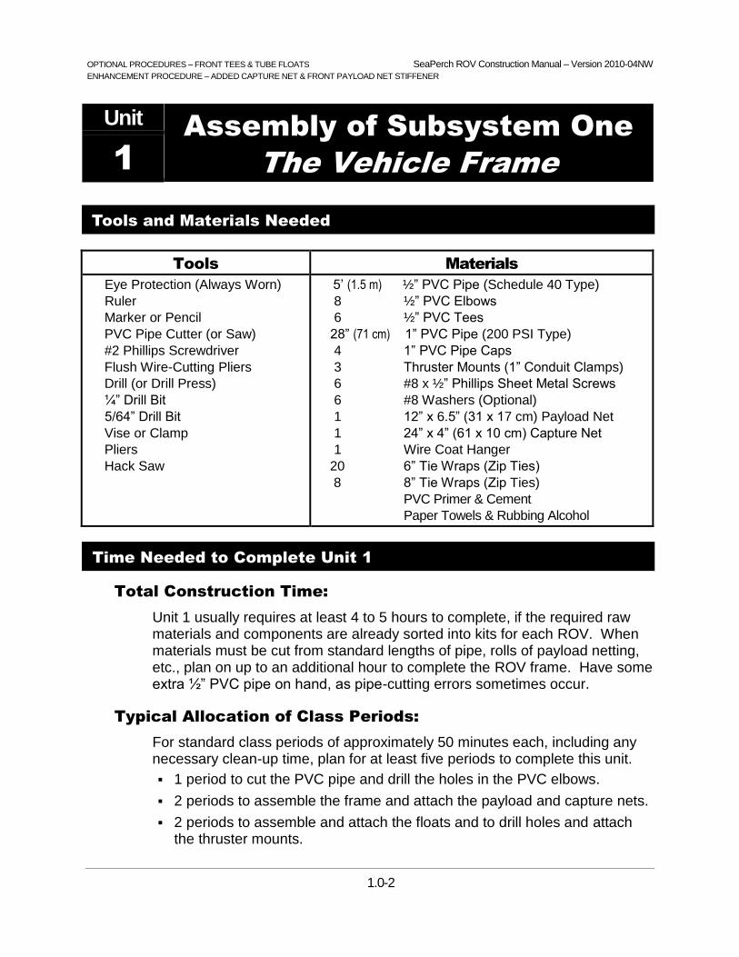
1.0-1
SeaPerch Program Office
The Society of Naval Architects and Marine Engineers
601 Pavonia Avenue
Jersey City, New Jersey 07306
Version 2010-04NW
Unit 1
SeaPerch
Remotely Operated Vehicle (ROV)
Assembly of Subsystem One
The Vehicle Frame
August 2010
The SeaPerch educational program was created by Harry Bohm and Vickie Jensen and published in their 1997 book "Build Your Own Underwater Robot and Other Wet Projects." The initial curriculum was developed by the Massachusetts Institute of Technology, and this version of the SeaPerch Construction Manual was provided under the Office of Naval Research National Naval Responsibility for Naval Engineering (NNRNE) Outreach initiative.

OPTIONAL PROCEDURES – FRONT TEES & TUBE FLOATS SeaPerch ROV Construction Manual – Version 2010-04NW
ENHANCEMENT PROCEDURE – ADDED CAPTURE NET & FRONT PAYLOAD NET STIFFENER
1.0-2
Unit Assembly of Subsystem One
The Vehicle Frame 1
Tools and Materials Needed
Tools Materials
Eye Protection (Always Worn)
Ruler
Marker or Pencil
PVC Pipe Cutter (or Saw)
#2 Phillips Screwdriver
Flush Wire-Cutting Pliers
Drill (or Drill Press)
¼” Drill Bit
5/64” Drill Bit
Vise or Clamp
Pliers
Hack Saw
5’ (1.5 m) ½” PVC Pipe (Schedule 40 Type)
8 ½” PVC Elbows
6 ½” PVC Tees
28” (71 cm) 1” PVC Pipe (200 PSI Type)
4 1” PVC Pipe Caps
3 Thruster Mounts (1” Conduit Clamps)
6 #8 x ½” Phillips Sheet Metal Screws
6 #8 Washers (Optional)
1 12” x 6.5” (31 x 17 cm) Payload Net
1 24” x 4” (61 x 10 cm) Capture Net
1 Wire Coat Hanger
20 6” Tie Wraps (Zip Ties)
8 8” Tie Wraps (Zip Ties)
PVC Primer & Cement
Paper Towels & Rubbing Alcohol
Time Needed to Complete Unit 1
Total Construction Time:
Unit 1 usually requires at least 4 to 5 hours to complete, if the required raw materials and components are already sorted into kits for each ROV. When materials must be cut from standard lengths of pipe, rolls of payload netting, etc., plan on up to an additional hour to complete the ROV frame. Have some extra ½” PVC pipe on hand, as pipe-cutting errors sometimes occur.
Typical Allocation of Class Periods:
For standard class periods of approximately 50 minutes each, including any necessary clean-up time, plan for at least five periods to complete this unit.
1 period to cut the PVC pipe and drill the holes in the PVC elbows.
2 periods to assemble the frame and attach the payload and capture nets.
2 periods to assemble and attach the floats and to drill holes and attach the thruster mounts.


OPTIONAL PROCEDURE 1.1 – FRONT TEES & PVC TUBE FLOATS SeaPerch ROV Construction Manual – Version 2010-04NW
1.1-1
Procedure 1.1 – Cut the Frame Parts
Tools:
Ruler
Marker (or Pencil)
PVC Pipe Cutter (or Saw)
Materials:
5’ (1.5 m) ½” PVC Pipe
Figure 1.1-1: PVC Pipe Cutter and Cut PVC Pipe
Sections, with Elbows and Tees
Pipe Cutting Tips:
PVC pipe can be cut in many ways, each of which has its own considerations:
Ratchet Style Pipe Cutters are the easiest and safest option. To open the cutter, pull the handles FAR apart. Then click them closed through the pipe by pumping the handles together and apart.
Non-ratchet Pipe Cutters are a cheaper alternative, but more difficult to use. Place the pipe in the cutter, push down LIGHTLY, and turn the cutter around the pipe slowly, applying light pressure, until it cuts through all the way. As with all pipe cutters, proceed slowly, giving the cutter time to do its work.
Hack Saws and other hand saws can cut through PVC, but are the most labor intensive option.
Band Saws are large pieces of shop equipment, and they can be very dangerous. Make sure to get
your teacher’s permission and supervision before using one.
Construction Steps:
1. From a cleanly-cut end of a length of ½” pipe, measure and cut the pieces listed below. Cut the longest pieces first, in case a mistake is made (smaller pieces may be cut from a longer piece that is accidentally cut too short). You will find the old adage, “measure twice; cut just once,” to be the best advice here. Try to cut straight, so that the ends of each piece are square with the sides, but don’t worry if they are not perfect.
Two pieces – 6½” (16.5 cm) long Four pieces – 4¾” (12.1 cm) long
Two pieces – 4½” (11.4 cm) long Two pieces – 4” (10.2 cm) long
Two pieces – 2½” (6.4 cm) long Four pieces – 1½” (3.8 cm) long
2. Write the length on each piece to keep track of cuts and to identify them later.


SeaPerch ROV Construction Manual – Version 2010-04NW
1.2-1
Procedure 1.2 – Drill the Drain Holes
Tools:
Hand Drill or Drill Press
1/4” Drill Bit
Vise or Clamp
Materials:
8 ½" PVC Elbows
Figure 1.2-1: Drain Hole Drilled in a PVC Elbow
NOTE: Drain holes are needed in the PVC elbows in order to let air escape and allow water to fill the frame when you put your SeaPerch ROV into the water and also for the water to drain when you take the SeaPerch out. Preventing air from being trapped within the frame will enable the vehicle to have consistent, repeatable buoyancy.
Drill Safety Reminders:
Drills can be dangerous pieces of equipment, but they are not difficult to operate properly. Always get your teacher’s permission and supervision before using a drill or other power tool. Always wear safety glasses when building your SeaPerch ROV (and when using any hand or power tool).
It is good practice to secure the object you are drilling in a vise or clamp before drilling. This keeps it steady, prevents it from spinning and hurting your hand if the drill should bind, and keeps your fingers away from the sharp drill bit while drilling. Be aware of what is behind the object you are drilling, to avoid extra holes in table tops or in other undesired places!
If you do not have a vise or clamp available, push the elbow onto one end of a long (5” or more) piece of PVC pipe, and hold the pipe while drilling the hole. DO NOT drill the elbow while holding it in your hand!
Construction Steps:
1. Inspect the PVC elbows to see if they have ¼” holes drilled in them (such as from a previous use). If they all have ¼” holes, skip to Procedure 1.3.
2. Secure a PVC elbow in a vise or clamp.
3. Place the ¼" drill bit in the drill (or drill press), and drill a hole in the corner of the elbow. Drilling from the interior of the elbow outward works best, as the bit can easily slip off of the rounded exterior of the elbow.
4. Repeat Steps 2 and 3 for other PVC elbows that don’t have the ¼” holes.


OPTIONAL PROCEDURE 1.3 – FRONT TEES & PVC TUBE FLOATS SeaPerch ROV Construction Manual – Version 2010-04NW
1.3-1
Figure 1.3-2: Frame Assembly
Procedure 1.3 – Assemble the Vehicle Frame
Tools:
None
Materials:
16 Cut Pieces of Pipe from Procedure 1.1
8 ½” PVC Elbows with Holes Drilled from Procedure 1.2
6 ½” PVC Tees
Figure 1.3-1: Assembled Vehicle Frame
Construction Steps:
1. Assemble the frame using the PVC parts as shown in Figure 1.3-2 below. Do not glue any of the connections. Orient the elbows that are near the top of the vehicle such that their holes point more upward than downward, to let air escape when the ROV is placed in the water. Orient those at the bottom such that their holes point more downward, to let the water flood in and out easily.


OPTIONAL PROCEDURE 1.4A – PVC TUBE FLOATS SeaPerch ROV Construction Manual – Version 2010-04NW
1.4A-1
Procedure 1.4A – Assemble the PVC Tube Floats
Tools:
PVC Pipe Cutter (or Saw)
Materials:
28” (71 cm) 1” PVC Pipe (200 PSI)
4 1” PVC Pipe Caps
PVC Primer
PVC Cement
Paper Towels
Figure 1.4A-1: PVC Flotation Tube Made from
1” PVC Pipe and PVC Pipe Caps
Construction Steps:
1. Cut two pieces of 1” PVC Pipe, exactly 14” (35.5 cm) each. Measure and cut carefully so that the completed flotation tubes will have the correct buoyancy.
2. Work in a WELL-VENTILATED area (outdoors or under a vent hood), with several layers of paper towel or newspaper to protect the work surface and floor area from stains. Apply a VERY SMALL amount of the purple PVC primer to each end of the two pipes, to about 1 inch from each end, as indicated in Figure 1.4A-2, being very careful not to drip the primer onto your clothes or other objects that could get stained. Similarly, apply the primer around the inside surface of each of the four end caps. The primer cleans the PVC and softens it in preparation for cementing the pieces together. Immediately close the primer container.
Figure 1.4A-2 Applying PVC Primer and Cement to Ends of Floatation Pipes

OPTIONAL PROCEDURE 1.4A – PVC TUBE FLOATS SeaPerch ROV Construction Manual – Version 2010-04NW
1.4A-2
3. Again, in a well-ventilated area and over the protected floor or table top, quickly apply a thin layer of PVC cement all of the way around one end of one of the 1” PVC pipes and one of the end caps. Glue just one end cap at a time. Immediately after applying the adhesive, push the end cap onto the pipe, twist it about a quarter turn, and hold it firmly in place for 30 seconds. Put the cap back on the adhesive container as soon as possible, to minimize the escape of vapors and to prevent the contents from drying out. Remove any excess glue from the outside of the pipe using a paper towel; discard the towel.
4. Repeat step 3 for the other end of the pipe, and then for each end of the other pipe, one end at a time. After all four end caps have been glued onto the pipes, discard the paper that was used to protect the table top and floor. When completed, each floatation tube should look like the one shown in Figure 1.4A-1.
Procedure 1.4A – Continued

OPTIONAL PROCEDURE 1.4B – FRONT TEES & PVC TUBE FLOATS SeaPerch ROV Construction Manual – Version 2010-04NW
1.4B-1
Procedure 1.4B – Install the Floats and Tighten the Frame
Tools:
Pliers
Flush Wire-Cutting Pliers
#2 Phillips Screwdriver (Optional)
Materials:
2 14” (36 cm) 1” PVC Floatation Tubes
Assembled Vehicle Frame
8 8” Tie Wraps (Zip Ties)
Figure 1.4B-1: Tube Floats Installed on Frame
Frame Rigidity Tip:
If you place the vehicle on a firm, flat surface and push down hard from all sides, or use the handle of a screwdriver to tap hard on the elbows, in each direction, you will be able to squeeze all the frame sections together tightly. This will help the frame hold its intended shape and make it easier to handle. Do this from time to time, or whenever any frame sections appear to be getting loose. Unless you are building a larger frame, or have a PVC component that remains loose, it is not necessary to glue or screw the joints.
Construction Steps:
1. Push all parts of your vehicle frame together HARD, so that no pipe sections are loose, and the vehicle holds its shape well.
2. Attach the two 1” PVC floatation tubes to the two top (6.5”) pipe sections of the frame using four 8-inch tie wraps on each tube, as shown in Figure 1.4B-1.
3. To tighten the tie wraps, turn the tubes at an angle relative to the top pipe, move the tie wraps to the center of the pipe and tighten them using pliers (not needle-nose pliers, which might bend or break), and then redistribute the tie wraps, re-straighten the tubes, and push them down over the top elbows. The extra width of the elbows will further tighten the ties and hold the tubes firmly in place.
4. Cut off the excess lengths of the tie wraps using flush wire-cutting pliers.


SeaPerch ROV Construction Manual – Version 2010-04NW
1.5-1
Procedure 1.5 – Attach the Thruster Mounts
Tools:
Marker (or Pencil)
Drill
5/64” Drill Bit
#2 Phillips Screwdriver
Materials:
Vehicle Frame
3 Thruster Mounts
6 #8 x ½” Phillips-Head Sheet Metal Screws
6 #8 Washers (Optional)
Figure 1.5-1: Thruster Mount Placement
Thruster Mounting Tips:
For now, don’t worry about where, around the circumference of the pipe sections, you attach the three thrusters’ mounts. Since we do not glue the joints in the PVC frame, we can change the angles of the mounts later by simply turning the pipe in its joints using a pair of pliers. It is easier to drill and attach the thruster mounts on the back (outside) of the frame… we’ll adjust them later.
This is a good time to think about how the angle of the thrusters affects the performance of the ROV. What angles will get you the best forward and backward thrust? What angles will get you the best turning ability? What is the best compromise for your mission needs?
Construction Steps:
1. Hold a thruster mount against the frame in the three locations shown in Figure 1.5-1, and, using a marker or pencil, mark the vehicle frame through the holes in the thruster mounts. Centering the mounts between the joints on the pipe is more important than placing them at a specific angle around the pipe (they can easily be turned later).
2. Using the 5/64” drill bit, drill holes through the six marks on the frame.
3. Using #8 screws and washers (washers are optional if the heads on your screws are large enough that they will not pass through the holes in the thruster mounts, and if the thruster mounts are metal or hard plastic). LOOSELY attach the thruster mounts to the frame. DO NOT over-tighten the screws and strip the holes in the PVC!! You will be removing the mounts later anyway to install the thrusters in them.


ENHANCEMENT PROCEDURE 1.6 – ADDED CAPTURE NET & FRONT PAYLOAD NET STIFFENER SeaPerch ROV Construction Manual – Version 2010-04NW
1.6-1
Procedure 1.6 – Attach the Payload Net
Tools:
Scissors
Pliers
Flush Wire-Cutting Pliers
Hack Saw
Materials:
Assembled Vehicle Frame
12” x 6.5” (31 x 17 cm) Payload Net
24” x 4” (61 x 10 cm) Capture Net
Wire Coat Hanger
20 6” Tie Wraps (Zip Ties)
Figure 1.6-1: Payload and Capture Nets and
Payload Net Stiffener Attached to Frame
ROV Painting Tip:
If you wish to paint your vehicle’s frame, do so before attaching the nets, and be sure to use waterproof paint. Also confirm that all vehicle pipe sections and fittings are as tight as possible and that the frame is squared-up before painting, as the parts may be difficult to move after the paint has dried. Painting the ROV should be avoided if parts such as PVC tees and elbows will later be “recycled” for use on another SeaPerch ROV.
Construction Steps:
1. Check the frame to ensure that all pipe sections and fittings are pressed tightly together and that the frame’s shape is as shown in Figure 1.6-1.
2. Place the payload net underneath the vehicle frame and trim it to size with scissors if necessary. Leave as little net as possible extending beyond the edges of the frame. The net is often a bit curved from being stored on a roll; make sure that it is placed under the frame with the concave side facing up.
3. Attach the payload net to the frame using about eight 6” tie wraps (also known as “cable ties” or “zip ties”). Pull them tight using pliers (NOT thin needle-nose pliers, as their tips may bend or even break when twisted!). Make sure the net is tight and flat on the bottom of the ROV, and that the front edge of the net is even with the front vertical pipes, NOT with the front of the PVC Tees.

ENHANCEMENT PROCEDURE 1.6 – ADDED CAPTURE NET & FRONT PAYLOAD NET STIFFENER SeaPerch ROV Construction Manual – Version 2010-04NW
1.6-2
4. Trim off the ends of the tie wraps using flush wire-cutting pliers (not scissors, which can leave very sharp ends that can easily scratch skin) as shown in Figure 1.6-2.
Figure 1.6-2: Payload Net Being Attached to the Bottom of Frame
5. Wrap one end of the “capture” net around the left front vertical post and attach it with tie wraps in two places; be sure to pass the tie wraps through the net mesh on both sides of the post as shown In Figure 1.6-3. Pull them tight, using pliers.
Figure 1.6-3: Capture Net Attached to the Left Front Vertical Post of Frame
6. Pass the capture net toward the rear of the vehicle frame, across and back up along the right side. Attach the net to the other front post as above. Then secure the sides of the capture net to the two vertical posts for the up / down thruster mount, with one tie wrap in the center of each. The capture net should be secured as shown in Figure 1.6-1.
Procedure 1.6 – Continued

ENHANCEMENT PROCEDURE 1.6 – ADDED CAPTURE NET & FRONT PAYLOAD NET STIFFENER SeaPerch ROV Construction Manual – Version 2010-04NW
1.6-3
7. Using a hack saw or other metal cutting tool, cut an 11-inch (28 cm) length of wire from an ordinary wire coat hanger. Simply scoring around the wire with the saw or cutter will allow the stiff wire to break cleanly when bent back and forth a few times using pliers. Bend up 2” (5.1 cm) of each end of the wire at 90o angles, into the shape shown in Figure 1.6-4.
Figure 1.6-4: Wire Stiffener for Payload Net
8. Attach the stiffener to the front of the payload net using six 6” wire ties, one on each side and four along the payload net, as shown in Figure 1.6-5.
Figure 1.6-5: Wire Stiffener Attached to Frame and Payload Net
9. Trim off all tie wrap ends with “flush” type wire cutter (to avoid leaving sharp tie wrap edges that can scratch you while handling the vehicle).
Congratulations! You have completed the frame for your SeaPerch ROV!
Procedure 1.6 – Continued
The Payload Net should be EVEN with the front vertical pipes, NOT with the front openings of the PVC Tees. This will simplify attachment of the wire net stiffener to the pipes.

2.0-1
SeaPerch Program Office
The Society of Naval Architects and Marine Engineers
601 Pavonia Avenue
Jersey City, New Jersey 07306
Version 2010-04NW
Unit 2
SeaPerch
Remotely Operated Vehicle (ROV)
Assembly of Subsystem Two
The Thrusters
August 2010
The SeaPerch educational program was created by Harry Bohm and Vickie Jensen and published in their 1997 book "Build Your Own Underwater Robot and Other Wet Projects." The initial curriculum was developed by the Massachusetts Institute of Technology, and this version of the SeaPerch Construction Manual was provided under the Office of Naval Research National Naval Responsibility for Naval Engineering (NNRNE) Outreach initiative.


OPTIONAL PROCEDURES – FILM CANISTERS, ALTERNATE MOTOR 1, & NON-ADHESIVE PROPELLER MOUNTING SeaPerch ROV Construction Manual – Version 2010-04NW
2.0-2
Unit Assembly of Subsystem Two
The Thrusters 2
Tools and Materials Needed
Tools Materials
Eye Protection (Always Worn)
Hand Drill or Drill Press
5/64” Drill Bit
1¼” Drill Bit (Forstner Preferred)
Small Electric Skillet
Metal Cup for Melting Wax
Pliers
Wire Stripper
Flush Wire-Cutting Pliers
Locking Long-Nose Pliers
Permanent Ink Marking Pen
Ruler and Scissors
Soldering Iron and Solder
#2 Phillips Screwdriver
Fine Sandpaper or Steel Wool
~40’ (12 m) Tether Cable (CAT 3, 5, 5e, or 6)
3 Plastic Vials or Film Canisters, with Caps
3 12 Volt DC motors
3 Propellers
3 3/8” Long Pieces of 1/8” Styrene Tubing
~½ Wax Bowl Ring, and Petroleum Jelly
1” (2.5 cm) Butyl Rubber Tape
24” (61 cm) #22 Stranded Hook-Up Wire, Red
24” (61 cm) #22 Stranded Hook-Up Wire, Black
1 12 Volt Battery
1 8” (20 cm) or Longer Wood Block (2x4”, “2x6”, or “4x4”)
Electrical Tape
Rubbing Alcohol, Water, Paper Towels
5 6” or 8" Tie Wraps (Zip Ties)
Time Needed to Complete Unit 2
Total Construction Time:
Unit 2 usually requires at least 6 to 7 hours to complete. More time should be allowed for if potting thrusters for a large number of ROVs.
Typical Allocation of Class Periods:
For standard class periods of approximately 50 minutes each, including any necessary clean-up time, plan for at least seven periods to complete this unit.
2 periods to test, mark, and wrap the motors for potting.
2 periods to solder wires to the motors and prepare thruster housings.
1 period to pot the motors (several periods for a large number of ROVs).
2 periods to mount the propellers onto the motor shafts (more for many ROVs, with shared tools) and attach the thrusters and tether cable.


SeaPerch ROV Construction Manual – Version 2010-04NW
2.1-1
Procedure 2.1 – Build a Motor Potting Holder (If Not Provided)
Tools:
Drill (or Drill Press)
¼” Drill Bit
1-3/8” Flat Drill Bit* (Or a “Forstner” Bit for a Flat-Bottomed Hole)
Permanent Ink Marker
Ruler
*Use a 1¼” Bit if Using Standard 35mm Film Canisters for the Thruster Housings
Materials:
1 Block of Wood, Such as a “2 x 4” (or “4 x 4”) at Least 8” (~20 cm) Long
Figure 2.1-1: Typical Hole Spacing for a Potting Holder
NOTE: A potting holder of some type is useful in order to securely hold the thruster housings in place during the motor-potting process, both while the melted wax is being poured and afterward, while it is hardening. Although a cardboard box or other raised surface, with holes at least ½” (13 cm) deep to accommodate the motor shafts, will suffice, a simple wooden holder is easy to build, is reusable, and provides more stable support for the thruster housings than a cardboard stand.
If a motor-potting holder is not already available, one can be quickly constructed by following the procedure below. The holes may be placed in any configuration convenient for placing / removing the thruster housings. If a potting holder of some type is already available, skip to Procedure 2.2.
Construction Steps:
1. Mark at least three drilling locations in the top of the wood block, as shown in Figure 2.1-1. (If a longer block is used, additional sets of three holes may be added, spaced similarly, for potting multiple sets of thruster motors.)
2. Using a 1-3/8” bit*, drill holes at least ½” (1.3 cm) deep for the thruster housings at the locations marked on the block. Drill the holes as nearly perpendicular to the surface as you can, and be careful to not drill all of the way through the block.
3. If central holes deep enough to accommodate the thruster motor shafts (which will protrude about ½" beyond the bottoms of the thruster housings) were not created by the drill bit in the step above, use a ¼” drill bit to drill a hole about 5/8” (1.6 cm) deep precisely in the center of each of the holes in the block.


OPTIONAL PROCEDURE – QUICK-DISCONNECT BATTERY CONNECTORS SeaPerch ROV Construction Manual – Version 2010-04NW
& AN ALTERNATE MOTOR TEST
2.2-1
Procedure 2.2 – Test the Motors and Mark Their Terminals’ Polarity
Tools:
Permanent Ink Marker
Materials:
3 12 Volt DC Motors
2 24” #22 Hook-Up Wire, Red and Black
1 12 Volt Battery (Confirm that It is Charged to at least 12 Volts)
Electrical Tape
Figure 2.2-1: Examples of Two Potential Thruster Motors
WARNING - TO AVOID ELECTRIC SHOCK AND POTENTIAL BURNS:
- DO NOT touch exposed wires when making connections to battery terminals.
- DO NOT touch the battery terminals with ANY metal object, especially tools!
- DO NOT CONNECT WIRE OR METAL FROM ONE BATTERY TERMINAL TO THE OTHER!
NOTE: Small 12-volt DC motors of various types are available for SeaPerch kits, such as those shown in Figure 2.2-1. Some may come with wire leads already attached. In that case, the wires must be removed prior to testing the motors and assembling the thrusters. Some motor shells may have more holes to cover than others. Some have two flat sides, and others are cylindrical. Motor shafts can have different lengths and diameters. Propellers and shaft couplers must be selected to be compatible with the motor shafts. Some motor shafts may require a different coupler size or a small bushing, sometimes with a little drilling, to properly attach the propellers.
It is necessary to mark the polarity of the motor “terminals” (electrical connections), even if polarity is already marked on the motors, as you will not be able to see such markings after you prepare the motors for potting by wrapping their shells with electrical tape.
Construction Steps:
1. Gather the red and black 24” (61 cm) hook-up wires to use as a pair of test wires (these are temporary; they will be used later to make the power cord and your control box in Unit 3) and some electrical tape.

OPTIONAL PROCEDURE – QUICK-DISCONNECT BATTERY CONNECTORS SeaPerch ROV Construction Manual – Version 2010-04NW
& AN ALTERNATE MOTOR TEST
2.2-2
2. Strip about 3/8” (1 cm) of insulation from both ends of the black hook-up wire, without cutting the copper strands inside.
3. Repeat Step 2 with the red hook-up wire.
4. If the motors have any wire leads soldered to their terminals, use a de-soldering tool (such as a vacuum solder remover or a solder-wicking braid) to remove the wires and any excess solder from the terminals.
5. Cut about 1” (2.5 cm) of electrical tape, and place it temporarily onto the shaft of each motor, wrapping it around the shaft with the end extending out like a flag, to help you see the motor’s spin direction when it is energized.
6. Connect the red and black wires to the two terminals on one of the motors (twist them through or around the terminals) and hold them temporarily in place with small pieces of electrical tape (the polarity does not matter).
7. Connect the other end of the black wire to the negative battery terminal, holding it in place with a small piece of electrical tape.
8. Briefly touch the loose end of the red wire to the positive terminal of the battery a few times, and observe which direction the flag on the motor shaft turns when looking into the front (long shaft end) of the motor. The shaft should spin rapidly. If it doesn’t, re-check the wire connections. If they are solid and the motor still doesn’t spin, or spins slowly, get a replacement motor.
If the shaft spins counter-clockwise, the polarity of the wires from the battery is the same as the polarity of the motor terminals (positive battery wire going to the positive terminal of the motor, and negative battery wire going to the negative terminal of the motor). This is the correct polarity for the SeaPerch ROV thrusters, so mark the motor terminal that is connected to the black wire to show that it is the “negative” terminal by using a black marker pen to color one side of that terminal black..
If the shaft spins clockwise, the polarity of the motor terminals does not match those of the battery. Mark the motor terminal connected to the red wire “negative” by coloring one side of that terminal black, as above.
9. Disconnect the black wire from the battery and both wires from the motor, and remove the tape flag from the motor shaft. Clean any tape residue from the shaft using a small piece of paper towel moistened with alcohol.
10. Repeat Steps 6 through 9 for the other two motors, but leave the test wires connected to the last motor tested, as it will be used again in Procedure 2.4.
Procedure 2.2 – Continued

OPTIONAL PROCEDURE 2.3 – ALTERNATE MOTOR 1 SeaPerch ROV Construction Manual – Version 2010-04NW
2.3-1
Procedure 2.3 – Seal the Motors So That Wax Cannot Get Inside
Tools:
Scissors
Materials:
3 12 Volt DC Motors
Electrical Tape
Figure 2.3-1: A Motor Sealed with Electrical Tape
NOTE: The purpose of sealing the motors, by wrapping them with electrical tape, as shown in Figure 2.3-1, is to keep the molten wax out of any holes in the motor shells during the thruster waterproofing process. Therefore, EVERY hole in the motor shells must be sealed (except the center area of the two ends where the shaft protrudes from the motor shell), and folds in the tape where wax could pass through must be avoided. The care with which this is done will help determine whether your thrusters will work and how long they will last.
Some motors used for SeaPerch ROVs may be larger than others. To ensure good coverage of the tape and minimize its thickness, so that the motors will still fit easily into the thruster housings (plastic vials or film canisters) with enough room for the waterproofing wax to flow around them, it is important to perform the wrapping process very carefully to minimize the overall diameter of each wrapped motor.
Construction Steps:
1. Make sure the markings placed earlier on the negative terminals of each of the motors have not rubbed off. It is important that you can identify the polarity of the terminals after covering the motors in tape. If the markings are not visible, repeat Procedure 2.2.
2. Study Steps 3 through 5 on the next two pages before beginning the tape-wrapping process. In those steps you will need to make sure that ALL holes are sealed, but ensure that the motors are still thin enough to easily slide into the thruster housings with enough room for melted wax to flow around the motors. A common problem to avoid is having the tape around the sides of the motors be thicker near the motor ends than it is for the rest of the motors' sides. Prevent this by cutting the pieces of tape that cover the motor ends so that they are flush with the sides as shown in the pictures, and having the edges of the side tapes slightly overlap onto the motor ends (rather than having the end tapes fold over onto the sides of the motors, increasing the thickness there).

OPTIONAL PROCEDURE 2.3 – ALTERNATE MOTOR 1 SeaPerch ROV Construction Manual – Version 2010-04NW
2.3-2
Figure 2.3-2: Tape Wrapping Process for the “Terminal” End of a Motor
Figure 2.3-3: Tape Wrapping Process for the “Shaft” End of a Motor
3. Cover both ends of the motor first with several short pieces of tape, and then cut around the motor ends using scissors to remove excess tape (cut at a tilt toward the motor to remove all tape that extends past the edge of the shell) using the process below.
On the terminal end, gently push each terminal through a piece of electrical tape, instead of trying to tape around the terminals. Use several pieces of tape to fully cover the end of the motor, allowing them to extend past the side of the motor shell. Carefully place each piece up along the side of the motor shaft boss (usually a raised flange area around the rear end of the shaft, in the center of the motor). Do not cover the rear tip of the motor shaft if it is exposed (it is on most motors), which could make the motor run slowly. Cutting two small slits in the edge of the tape, just at the sides of the boss, will allow the tape to fit snugly and flat around the boss area.
After the tape pieces have been placed all around the end of the motor, cut off all tape that extends past the edge of the motor shell, leaving the end completely covered, except for the boss area. Figure 2.3-2 shows the taping process for the terminal end of the motor.
On the front (shaft) end of the motor, again place multiple pieces of tape right up to the edge of the shaft bearing. Cut them flush at the edge of the motor as before. Figure 2.3-3 shows the taping process for the shaft end of the motor.
Procedure 2.3 – Continued

OPTIONAL PROCEDURE 2.3 – ALTERNATE MOTOR 1 SeaPerch ROV Construction Manual – Version 2010-04NW
2.3-3
Figure 2.3-4: Final Tape Wrapping Process for the Motors
4. Wrap a longer piece of tape around the sides of the motor. Start at one end with the edge of the tape extending about 1/16” (~2 mm) past the end of the motor, so that it can be folded down to form a good seal. Tape only a single layer around the motor, overlapping each piece only about 1/8” (3 mm) at its ends. Cut about six small slits around the curved edge of the tape that extends past the end of the motor, to aid in folding it down without wrinkles. Then fold it over the end as smoothly as possible. Figure 2.3-4 shows the final taping process for both ends of the motor.
5. Similarly, at the other end of the motor, place the edge of the tape to about 1/16” (~2 mm) past the end, wrap it around the motor, overlapping slightly as before, and then use about six small cuts around the curved edge to help make a tight seal when you fold the tape over that end.
6. Repeat Steps 3 through 5 for the other two motors.
7. Make sure that ALL holes in the motors are sealed well by pressing, rubbing, and squeezing the tape with your fingers over the entire surface of each motor shell.
Procedure 2.3 – Continued


OPTIONAL PROCEDURE 2.4 – FILM CANISTERS & 0.078” MOTOR SHAFTS SeaPerch ROV Construction Manual – Version 2010-04NW
2.4-1
Procedure 2.4 – Drill Holes in the Thruster Housings
Tools:
Drill or Drill Press
5/64” Drill Bit (See the Note Below for an Alternate Size)
12-Volt DC Motor with Test Wires Connected (from Procedure 2.2)
12 Volt Battery
Materials:
3 Film Canisters with Caps
Electrical Tape
Figure 2.4-1: Drilled Thruster Housing (Film Canister)
NOTE: The standard motors typically used with SeaPerch ROVs have a 0.091” shaft diameter, which matches well with the 3/32” holes drilled in the thruster housings (plastic vials or film canisters) to form a good waterproof seal. However, this optional procedure uses a different motor with a smaller, 0.078” shaft diameter. If you are instead using the standard SeaPerch motor with a shaft diameter of 0.091”, you should substitute a 3/32” drill bit in the procedure steps below that call for a 5/64” drill bit, so that the motor shafts will not be too tight for the holes drilled in the thruster housings.
Drill Safety Reminder:
Always get your teacher’s permission before using a drill or other power tool. Check to verify that you are still wearing your safety glasses. Secure the object that you are drilling in a vise or clamp before drilling. Do not drill while holding the object in your hand!
Construction Steps:
1. Using the 5/64” drill bit, drill a hole in the center of each of the three film canister caps. The holes in the caps are where the motor wires pass through, so high precision in hole placement is not essential.
2. Again using the 5/64” drill bit, carefully drill a hole in the exact center of the bottom of each thruster housing (see Figure 2.4-1) as follows. This hole is where the motor shaft passes through; it forms the shaft seal, so it is VERY IMPORTANT that these holes are drilled with great care. First, scrape any plastic lumps off of the center of the housing bottom with your fingernail or a small tool. Then carefully and slowly drill the hole straight into the very CENTER of the thruster housing. Pull the drill straight out to avoid enlarging the hole.

OPTIONAL PROCEDURE 2.4 – FILM CANISTERS & 0.078” MOTOR SHAFTS SeaPerch ROV Construction Manual – Version 2010-04NW
2.4-2
3. Carefully remove any plastic burrs from the hole in the bottom of the thruster housing, which may be left after the drilling process. When using the standard plastic vials, made of a rather soft material, some burrs usually remain in or around the holes after drilling. Burrs may also remain when using 35mm film canisters. It is essential to remove these burrs, as they can make it difficult to get the motor shaft to pass through the hole during the waterproofing process. To clear plastic burrs, remove the 5/64” drill bit from the drill and pass it by hand through the hole, from both directions, a number of times. As the drill bit shaft at the non-cutting end of the bit starts to emerge from the hole, cut or scrape off any burrs that come through with that solid part of the bit. Repeat this process until the hole is completely clear.
4. Polish the holes that you drilled in the bottoms of the thruster housings to the perfect size using the shaft of a running motor, as follows. Locate the motor and test wires that were used in Procedure 2.2, and connect the test leads to the battery (the polarity does not matter) using small pieces of electrical tape. Carefully push the spinning shaft of the motor into the hole and hold it there for a few seconds, until the motor spins freely without slowing down. Do not hold it there too long, or at an angle, as you might melt the plastic and overly enlarge the hole, making the shaft too loose. If that should happen, obtain a replacement film canister and repeat this procedure.
5. After polishing is completed for all three thruster housings, disconnect the test leads from the battery and remove the test wires from the motor. Set the test wires aside for use later, in Unit 3.
Procedure 2.4 – Continued

SeaPerch ROV Construction Manual – Version 2010-04NW
2.5-1
Tips on Soldering – Safety and Techniques
Soldering Safety Reminders:
Eye Protection: Always wear safety glasses or goggles when soldering or near someone who is soldering.
Solder Hazards: Some solder contains lead, which is poisonous. Never put it in your mouth, and wash your hands after working with it. Solder also contains a chemical flux to aid the soldering process. This causes smoke when soldering. Avoid breathing the fumes.
Don’t Get Burned: Soldering irons are obviously hot, so care must be taken when handling them. However, care must also be taken when not handling them. Make sure that the hot soldering iron is placed securely in a holder or stand when not in use so that it cannot burn you, its own cord, or anything or anyone else in the work area. Always allow the soldering iron to cool completely before maintaining or changing the tip, or returning it to its storage location.
Soldering Technique Tips:
If you have not soldered before, ask your teacher to show you how, and practice on some pieces of scrap wire.
Working With Stranded Wire and Small Terminals: For best results when using stranded wire, always twist the many wire strands together immediately after you strip off the insulation, so that they don’t fray and break off (or touch another connection). Then poke the wire through the hole in the terminal on a motor or a switch, twist it back around the terminal, and squeeze it with needle-nose pliers to make a good mechanical connection. It is important to have a solid connection before soldering, both for good heat transfer throughout the connection while soldering and to create a strong solder joint.
Care for Soldering Irons: Always clean the heated soldering iron tip (by briefly wiping it on a moist sponge pad) immediately before (and after) soldering, and “re-tin” the tip with a little fresh solder just before moving to the connection to be soldered. After soldering, always quickly clean (wipe on the damp sponge) and re-tin (apply some fresh solder) the soldering iron tip. This is essential to keep the tip in good shape for soldering the next connection.
Soldering: Besides protecting the tip from oxidation, applying a little solder to the tip of the soldering iron helps to transfer heat to the junction being soldered. Apply heat with the side of the soldering iron tip (not the point, which has very small surface area, so it can’t conduct much heat) for a few seconds to get the connection up to solder-melting temperature. Be careful not to get it so hot that you melt any surrounding plastic, or the wire insulation. (Overheating a small toggle switch can actually melt some of its internal components, causing it to fail! – So try to work quickly on each terminal, but wait 30 seconds or so before soldering another terminal.)
Once the parts are up to temperature, melt some solder onto the connection; not just onto the soldering iron tip. As the solder melts, it should flow into the connection. You will usually need to feed about a centimeter of thin solder into a typical connection (don’t use too much and make the solder joint too big!). After just a second or so, it should flow freely in between the wire strands and over the terminal when the terminal is hot enough. Immediately remove the solder, but hold the soldering iron on the connection for just a second or so longer to make sure that all solder has attained its full melting temperature, and then remove the soldering iron. Try not to move the connection at all until the solder cools and hardens (this takes just a few seconds). If you move the wire before the solder has cooled, the solder will tend to crystallize and make a poor electrical connection.
Keeping Solder Tangle-Free: Although solder frequently comes on a large spool, it is often provided as a smaller coil, either in a box or a tube: If your solder comes as a small coil, be sure to keep it inside the container, only pulling out a few inches of solder at a time as it is needed. This will keep the coil from getting tangled and becoming very difficult to use. It is a good practice to secure the top of a plastic tube of solder using a small piece of electrical tape, so that the solder coil cannot accidentally fall out and get tangled. If you are issued just a short length of solder at a time, such as from a large spool, coil it around a pen or pencil to help keep it from getting lost or tangled.


OPTIONAL PROCEDURE 2.5 – ALTERNATE MOTOR 1 SeaPerch ROV Construction Manual – Version 2010-04NW
2.5-2
Figure 2.5-2: Tether Cable’s Color-Coded Wire Pairs
Procedure 2.5 – Connect the Tether Cable Wires to the Motors
Tools:
Ruler and Scissors
Soldering Iron and Solder
Scissors or CAT 3/5/6 Cable Stripper
Materials:
3 Motors Sealed with Tape
3 Thruster Housings and Caps with Holes Drilled (from Procedure 2.4)
CAT 3, 5, or 6 Tether Cable
Figure 2.5-1: Tether Cable Wires Soldered to a Motor
NOTE: Each motor must be connected to one of the color-coded pairs of wires in the tether cable, as shown in Figure 2.5-1. The CAT 3, CAT 5, or CAT 6 cable types have four wire pairs inside. Three of them will be used for the standard SeaPerch ROV.
Construction Steps:
1. On one end of the tether cable, strip off about 15” (38 cm) of the outer sheath, being very careful not to nick any of the inner wires. This can most easily be done with a cable stripping tool designed specifically for CAT 3/5/6 type cable. If using scissors, use extreme care not to cut the insulation on the inner wires (using a knife is not recommended.)
2. Separate the four wire pairs in the stripped section, as shown in Figure 2.5-2 (in some tether cables, the wires may not be twisted into pairs). The brown pair is not used in the basic SeaPerch, and can be left hanging for now (do not cut this pair off, as it could be used later for an accessory item, such as a sensor, light, or manipulator).
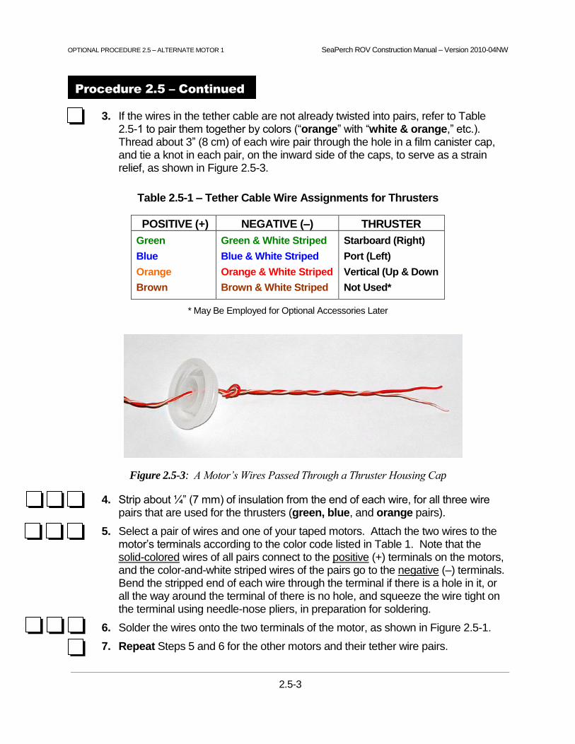
OPTIONAL PROCEDURE 2.5 – ALTERNATE MOTOR 1 SeaPerch ROV Construction Manual – Version 2010-04NW
2.5-3
3. If the wires in the tether cable are not already twisted into pairs, refer to Table 2.5-1 to pair them together by colors (“orange” with “white & orange,” etc.). Thread about 3” (8 cm) of each wire pair through the hole in a film canister cap, and tie a knot in each pair, on the inward side of the caps, to serve as a strain relief, as shown in Figure 2.5-3.
Table 2.5-1 – Tether Cable Wire Assignments for Thrusters
POSITIVE (+) NEGATIVE (–) THRUSTER
Green
Blue
Orange
Brown
Green & White Striped
Blue & White Striped
Orange & White Striped
Brown & White Striped
Starboard (Right)
Port (Left)
Vertical (Up & Down
Not Used*
* May Be Employed for Optional Accessories Later
Figure 2.5-3: A Motor’s Wires Passed Through a Thruster Housing Cap
4. Strip about ¼” (7 mm) of insulation from the end of each wire, for all three wire pairs that are used for the thrusters (green, blue, and orange pairs).
5. Select a pair of wires and one of your taped motors. Attach the two wires to the motor’s terminals according to the color code listed in Table 1. Note that the solid-colored wires of all pairs connect to the positive (+) terminals on the motors, and the color-and-white striped wires of the pairs go to the negative (–) terminals. Bend the stripped end of each wire through the terminal if there is a hole in it, or all the way around the terminal of there is no hole, and squeeze the wire tight on the terminal using needle-nose pliers, in preparation for soldering.
6. Solder the wires onto the two terminals of the motor, as shown in Figure 2.5-1.
7. Repeat Steps 5 and 6 for the other motors and their tether wire pairs.
Procedure 2.5 – Continued

SeaPerch ROV Construction Manual – Version 2010-04NW
2.6-1
Tips on Wax Melting – Safety and Techniques
Wax Melting Safety Reminders:
Eye Protection: Always wear safety glasses or goggles when working with potting wax.
Wax Handling: Bowl ring wax is made from petrolatum – basically the same type of material that, when more refined, becomes common petroleum jelly. It is safe to handle when cooled, but quite sticky, and difficult to remove if it solidifies on clothing. After handling bowl ring wax, wash your hands with very warm water and soap. Do not ingest the wax.
Don’t Get Burned: Bowl ring wax usually melts at a rather low 150 degrees Fahrenheit (F). The wax-melting approach used for SeaPerch ROVs is to melt the wax in a water bath, usually employing an electric skillet to heat the water (and wax). It is important NOT to let the water evaporate (keep adding water to maintain it at about ½” to 1” deep); otherwise, the wax can get VERY hot. Although its flash point is over 500 degrees F, the manufacturers usually recommend not exceeding 200 degrees F. Obviously, if the wax is allowed to get too hot, serious skin burns are possible; more sensitive skin or large quantities of hot wax may cause burns. In case of a burn, quickly rinse the area with LOTS of cold water and seek medical attention.
Don’t Have a Melt-Down: Too-hot wax, such as from using a hot plate without a water bath, has been shown to actually melt the thruster housings! For this reason, and the safety reasons noted above, use of a thermometer for the wax cup(s) is recommended. If a thermometer is not available, the best advice is to keep the water bath below the boiling point, and adjust the skillet temperature to low or medium, so that the wax just reaches its melting point, or a little higher, about 160 degrees F. The goal is for the wax to be hot enough that it will not harden immediately when poured into the thruster housings, but cool enough to avoid burn hazards.
Wax Melting Technique Tips:
1. To facilitate cleanup, put a drop cloth on the work bench, on the floor below it, and on the wall behind it. When installing caps, stand back to avoid getting wax on you or your (or others’) clothes.
2. Start the wax melting early, at least an hour before class time on motor-potting days.
3. Put small weights (such as lead sinkers) in your wax-melting cup(s), to prevent floating in the water.
4. Try to find metal cups with insulated handles that can hang over the side of the electric skillet or other water-bath heating device. This makes handling and pouring much easier than using tongs or gloves on a hot cup.
5. One wax ring will pot about six thrusters, but plan on some spillage; have extra wax on hand!
6. Should wax run short, spilled wax can be scraped up from the potting holder, table top, or even the outside of the cooling thruster housings and returned to the cup(s) to be re-melted.
Example of a Student’s Safety Glasses Saving the Day!
Watch Out for Squirting Wax: Wax can squirt quite a distance when the caps are pressed onto the thruster housings if the task is done very quickly (wax can jet out of the hole in the cap). Wearing an apron and gloves (latex, nitrile, etc.) during the motor potting process is recommended. Holding a paper towel over the cap as it is pressed on will help to prevent wax from squirting beyond the area of the housing. The inside-seal type housings (some film canisters) tend to squirt wax farther than the outside seal types, but either can be a squirting hazard. The picture to the right says it all; wear that eye protection!


OPTIONAL PROCEDURE 2.6A – FILM CANISTERS & ALTERNATE MOTOR 1 SeaPerch ROV Construction Manual – Version 2010-04NW
2.6-2
Figure 2.6-2: Drill Bit Used to Clear a
Motor Shaft Hole in a Thruster Housing
CLOGGED HOLECLOGGED HOLE
DRILL BIT
PASSED THROUGH
HOLE FROM INSIDE TO CLEAR
DRILL BIT
PASSED THROUGH
HOLE FROM INSIDE TO CLEAR
CLOGGED HOLECLOGGED HOLE
DRILL BIT
PASSED THROUGH
HOLE FROM INSIDE TO CLEAR
DRILL BIT
PASSED THROUGH
HOLE FROM INSIDE TO CLEAR
Procedure 2.6 – Pot (Waterproof) the Motors with Wax
Tools:
Metal Cup(s)
Electric Skillet
Potting Holder
Scissors
Apron / Gloves (Optional)
Materials:
3 Motors Sealed with Tape
3 Film Canisters and Caps with Holes Drilled (from Procedure 2.4)
Wax Bowl Ring (~½ Ring Needed Per ROV)
Electrical Tape
Petroleum Jelly
Water and Paper Towels
Figure 2.6-1: Motor Waterproofed by Potting in Wax
NOTE: Each motor will be potted into its thruster housing using melted wax, as shown in Figure 2.6-1. Wearing an apron and using protective gloves is recommended during the potting process. Review the wax-melting tips on page 2.6-1 before proceeding.
Construction Steps:
1. Check the shaft hole in each thruster housing to ensure that it is clear of any plastic burrs. Dry-fit a motor’s shaft, from the outside of each housing, to ensure that it fits into the hole, but is not too tight. A shaft fits properly when the motor will slowly fall out when the housing is held with the motor below it. If the hole is obstructed or the shaft is too tight, simply pass a 5/64” drill bit straight through the hole, from the inside of the housing, a few times (without twisting it) as needed to correct the problem. See Figure 2.6-2.

OPTIONAL PROCEDURE 2.6A – FILM CANISTERS & ALTERNATE MOTOR 1 SeaPerch ROV Construction Manual – Version 2010-04NW
2.6-3
Figure 2.6-4: Petroleum Jelly Placed at the Base of a Motor’s Shaft
Figure 2.6-3: Wax Melted in Cup
in an Electric Skillet with Water to
Help Regulate the Temperature
2. Your teacher will probably have already melted wax for your use, using a set-up similar to that shown in Figure 2.6-3. If not, see the wax melting tips on page 2.6-1.
3. Check to see that everyone who is near the wax potting area has put on EYE PROTECTION before anyone begins to work with the hot wax.
4. Dip the ends (1/2 inch) of the brown wire pair in the melted wax to waterproof them.
5. Place the three thruster housings into the potting holder prepared in Procedure 2.1, or other appropriate stand that will allow the thruster housings to sit level for wax cooling while they have the motor shafts protruding from their bottoms.
6. Just before starting the motor-potting process, hold the motors tightly in your closed hand for a minute or so, to warm them up a bit. This will help to prevent rapid cooling of the wax and give you a little more time to settle each motor into position at the bottom of its thruster housing.
7. Place a small dab of petroleum jelly at the base of the motor’s shaft as shown in Figure 2.6-4. This is recommended to help keep water from getting into the motor while in use.
8. Pick up one of the thruster housings and carefully insert a motor so that just the tip of the motor’s shaft protrudes from the hole in the bottom. Support the shaft’s tip with a finger to keep the motor from settling all the way into the bottom of the housing, as shown in Figures 2.6-5 and 2.6-6.
9. Carefully lift the cup of molten wax from the heated water (if it has no handle, use pliers), and, while continuing to support the shaft tip, pour about ¼” (7 mm) of wax (not more!) into the thruster housing, along the side of the motor, as shown in Figure 2.6-7. Then remove the finger from the tip of the shaft and gently settle the motor down into the bottom of the thruster housing. The wax will push part of the way up around the sides of the motor, but it should not move all of the way to the top of the motor, or above it. See Figures 2.6-8 and 2.6-9. Carefully place the thruster housing into the potting holder to allow the wax to solidify before performing the additional wax pours.
Procedure 2.6 – Continued

OPTIONAL PROCEDURE 2.6A – FILM CANISTERS & ALTERNATE MOTOR 1 SeaPerch ROV Construction Manual – Version 2010-04NW
2.6-4
Figure 2.6-6: Motor Shaft Tip
Supported for
Initial Wax Pour
Figure 2.6-8: Settling Motor into
Melted Wax at
Bottom of Housing
Figure 2.6-9: Wax Moved Part
Way Up Around
Motor
Figure 2.6-5: Motor Shaft Tip
Inserted into Hole
in Housing
Figure 2.6-7: Pouring Initial
¼” of Melted
Wax into Housing
Figure 2.6-11: Wax
Filled to ½” from the Top
of the Thruster Housing
Figure 2.6-10: Placing
Petroleum Jelly on Rear
Tips of Motor Shafts
10. Repeat Steps 5 through 8 for the other two motors.
11. Let the wax cool and harden for several minutes. One end of each motor is now sealed in the wax, so be careful not to push on the motor shafts and break the seals. Once all three of your housings have a motor in them, and have cooled, you will fill them the rest of the way with wax, in two steps.
12. Place a dab of petroleum jelly on the rear tip of each motor’s shaft, as shown in Figure 2.6.10. Do this for all three motors now, as the step is easy to accidentally skip later.
13. Again carefully lifting the hot container of wax, fill one thruster housing with wax up to about ½” (13 mm) below the top, as shown in Figure 2.6-11. Pour the wax so that it fills in all the air spaces around the motor. Lift your container and look at it from the side to see if you have any air bubbles. Quickly try to get any bubbles out while the wax is still liquid by gently tilting and squeezing the housing if needed.
14. Return the housing to the potting holder to allow the wax to solidify, and repeat Step 13 for the other two motors.
Procedure 2.6 – Continued
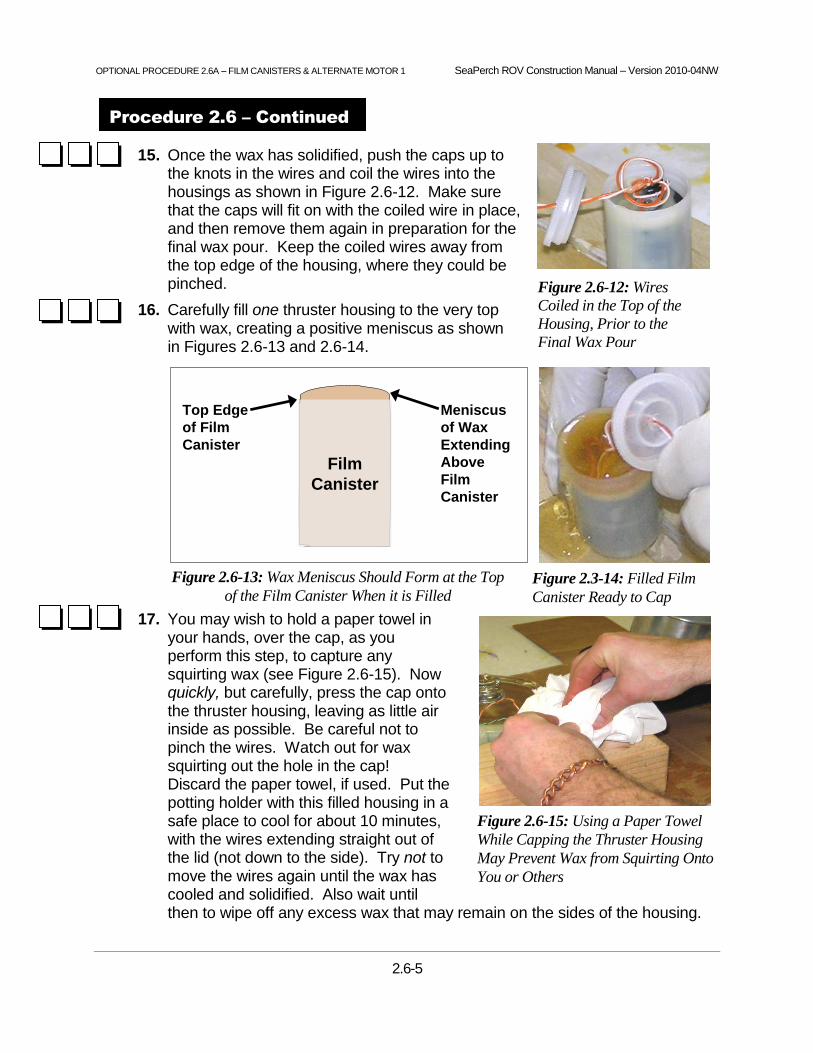
OPTIONAL PROCEDURE 2.6A – FILM CANISTERS & ALTERNATE MOTOR 1 SeaPerch ROV Construction Manual – Version 2010-04NW
2.6-5
Film
Canister
Top Edge
of Film
Canister
Meniscus
of Wax
Extending
Above
Film
Canister
Figure 2.3-14: Filled Film
Canister Ready to Cap
Figure 2.6-13: Wax Meniscus Should Form at the Top
of the Film Canister When it is Filled
Figure 2.6-12: Wires
Coiled in the Top of the
Housing, Prior to the
Final Wax Pour
Figure 2.6-15: Using a Paper Towel
While Capping the Thruster Housing
May Prevent Wax from Squirting Onto
You or Others
15. Once the wax has solidified, push the caps up to the knots in the wires and coil the wires into the housings as shown in Figure 2.6-12. Make sure that the caps will fit on with the coiled wire in place, and then remove them again in preparation for the final wax pour. Keep the coiled wires away from the top edge of the housing, where they could be pinched.
16. Carefully fill one thruster housing to the very top with wax, creating a positive meniscus as shown in Figures 2.6-13 and 2.6-14.
17. You may wish to hold a paper towel in your hands, over the cap, as you perform this step, to capture any squirting wax (see Figure 2.6-15). Now quickly, but carefully, press the cap onto the thruster housing, leaving as little air inside as possible. Be careful not to pinch the wires. Watch out for wax squirting out the hole in the cap! Discard the paper towel, if used. Put the potting holder with this filled housing in a safe place to cool for about 10 minutes, with the wires extending straight out of the lid (not down to the side). Try not to move the wires again until the wax has cooled and solidified. Also wait until then to wipe off any excess wax that may remain on the sides of the housing.
Procedure 2.6 – Continued

OPTIONAL PROCEDURE 2.6A – FILM CANISTERS & ALTERNATE MOTOR 1 SeaPerch ROV Construction Manual – Version 2010-04NW
2.6-6
Figure 2.6-16: Three Motors
Potted into Thruster Housings
18. Repeat Steps 15 and 16 for the other two motors. The potted motors should look like those in Figure 2.6-16 when they have been completed, after cooling. Handle the wires and potted motors very carefully throughout the remaining construction steps in order to minimize the chance of damage to the shaft or tether wire sealing areas.
19. On the loose end of the tether cable (that does not have the thrusters installed), strip off about 4” (10 cm) of the outer sheath, being very careful not to nick any of the inner wires. This can most easily be done with a cable stripper designed for CAT 3/5/6 type cable. If using scissors, use extreme care not to cut the insulation on the inner wires. (Using a knife is not recommended.)
20. Separate the wires pairs, untwist them for about 1 inch, and strip ¼” of insulation off all wires except for the brown / brown-white striped pair.
21. One at a time, test each thruster by momentarily touching the two wires from its color-coded wire pair to the two terminals of a 12 volt battery (the polarity does not matter).
The motor shaft should spin rapidly, indicating that the thruster is good.
If it does not spin, or spins slowly, gently twist it in both directions by hand or, if it seems stuck, use pliers to turn the shaft, and repeat the above test with the battery.
If it still does not work, inspect the wires for nicks that may have broken a wire. If a wire has been broken, it can be repaired by stripping about ¼” of insulation from the broken ends and splicing them back together (twist and solder them, and cover the connection with electrical tape).
If the thruster still does not work, it will need to be replaced by obtaining another thruster housing and motor, cutting the thruster wire as close as possible to the non-working thruster housing, and repeating procedures 2.2 through 2.6 for the new thruster. Alternately, the non-working thruster can be disassembled to see if a wire may have broken away from one of the electrical terminals on the motor. If that is the reason for the failure (rather than wax having somehow entered the motor shell), the wax can be removed from the back area of the housing to allow the connection to be repaired, and then the wax can be replaced. However, starting with a new thruster may be easier.
Test any new or repaired thrusters as above to make sure that they spin properly.
Procedure 2.6 – Continued


OPTIONAL PROCEDURE 2.7 – NO-ADHESIVE PROPELLER MOUNTING SeaPerch ROV Construction Manual – Version 2010-04NW
2.7-1
Procedure 2.7 – Mount the Propellers Onto the Motors’ Shafts
Tools:
5/64” Drill Bit
Sandpaper (or Steel Wool)
Locking Thin-Nosed Pliers
Materials:
3 Potted Motors
3 Propellers
3 3/8 inch (10 mm) Long, 1/8 inch (3.2 mm) Diam., Styrene Plastic Bushings
Paper Towels
Rubbing Alcohol
Figure 2.7-1: Propeller Mounted on a Motor’s Shaft
NOTE: Various propeller types may be used on SeaPerch ROVs. This vehicle will use small boat (underwater) propellers. They fit onto the shafts of the thruster motors, as shown in Figure 2.7-1. A 1/8” diameter plastic bushing will be used to match the size of the hole in the propeller to the diameter of the motor shaft. Due to the tight fit of the bushing and propeller, no adhesive is needed for the propeller to be held onto the shaft.
Construction Steps:
1. Wipe the shafts of each of the three motors using a paper towel and rubbing alcohol to remove any tape residue, excess wax, or petroleum jelly that may be left after the potting process.
2. Use a small piece of sandpaper (or steel wool) to roughen the surface of each of the motor shafts. Then wipe them again with alcohol and a clean paper towel (not the one used to remove wax above).
3. Use the cutting end of a 5/64” drill bit, twisting it by hand (do not use a drill motor) slowly back and forth, to gently ream out the inside of the three plastic bushings. Ream them from both ends. The drill bit should just emerge from the opposite end of the bushing when it is reamed sufficiently. STOP reaming when the bit first emerges so as not to overly enlarge the inside of the bushing.
IMPORTANT: Some pieces of styrene plastic bushing material may have a large enough inside diameter to be used without reaming (Step 3). If the inside diameter of the bushing is enlarged too much, the propeller may later slip and spin slowly in use, or even fall off, so it is essential that the bushings be very tight on the motor shafts. SKIP TO STEP 4 AND 5 NOW to try pushing a bushing onto a motor shaft without reaming it first. If it slides on (while being pushed with very firm pressure), continue to Step 6. IF THE BUSHING IS TOO TIGHT TO FIT ON, PERFORM STEP 3 BELOW and then continue.

OPTIONAL PROCEDURE 2.7 – NO-ADHESIVE PROPELLER MOUNTING SeaPerch ROV Construction Manual – Version 2010-04NW
2.7-2
Figure 2.7-3: Installing a Plastic Bushing
4. Tightly clamp the tip of the locking thin-nosed pliers to the motor shaft as shown in Figure 2.7-2. Re-adjust the pliers as needed to clamp on tightly, and place just the tip of the pliers on the shaft, as close to the face of the thruster housing as possible. Use only the clamped pliers to hold the thruster while applying pressure in the following steps. Do not hold or press on the thruster housing at all, as that may damage the wax seal for the motor's shaft.
Figure 2.7-2: Placement of Locking Thin-Nosed Pliers, for Propeller Mounting
5. Press a plastic bushing onto one of the motor shafts, held steady in the grip of the locking thin-nosed pliers, as shown in Figure 2.7-3. It should take a few seconds of very firm pressure to slide it on. If it is too small to go onto the shaft, ream it out slightly more using the 5/64” drill bit and try again. If it is too loose (easy to pull off), repeat Step 3 to make a replacement bushing.
6. Examine a propeller, and note that one side has a slot (groove) in it. This is the side that must face toward the thruster housing when the propeller is installed.
7. While still holding the thruster by the pliers clamped to its shaft, and NOT holding or pressing on the thruster housing at all, firmly press the propeller onto the motor shaft, with the slotted side placed nearest the thruster housing, as shown in Figure 2.7-4.
8. Repeat Steps 4 through 7 for each of the other two thrusters and propellers.
Figure 2.7-4: Propeller and Bushing
Mounted on a Motor Shaft
Procedure 2.7 – Continued

OPTIONAL PROCEDURE 2.8 – FILM CANISTERS & NO-ADHESIVE PROPELLERS SeaPerch ROV Construction Manual – Version 2010-04NW
2.8-1
Procedure 2.8 – Mount the Thrusters Onto the Vehicle Frame
Tools:
#2 Phillips Screwdriver
Pliers
Materials:
3 Assembled Thrusters
Assembled Frame
Electrical Tape
Figure 2.8-1: Thrusters Mounted on ROV Frame
NOTES: The thruster housings should be positioned within the thruster mounts such that the back end of each motor (estimate where it is inside the thruster if you can’t see it) is placed right under the thruster mount. The mounts should not be clamped over the very back of the thruster housings, where there is only wax, nor over the center of the motors, where they might squeeze the motor casings. Placing them over the back end of the motors will best resist the pressure of the tightened thruster mounts.
The tightness of the thrusters in their mounts depends upon the size of the thruster housings as well as how far apart the mounting holes were drilled. If, after tightening a thruster into its mount, it is still too loose, remove it and put a few wraps of electrical tape around the thruster housing, just at the point where it will be clamped under the mount, and then reinstall the thruster. For standard 35mm film canisters, about 8 wraps of electrical tape will usually be the right amount for a snug fit.
Construction Steps:
1. Loosen, or remove, the thruster mounts using a #2 Phillips screwdriver.
2. Place the thrusters in the mounts according to Table 2.8-1. Mount the vertical thruster with its propeller pointing upward, and orient the rear thrusters so that the propellers are not pointed so far outward that they become the outermost part of the vehicle (they could be damaged by contact with other objects).
Table 2.8-1 – Thrusters Identification for Placement on Vehicle Frame
WIRE PAIR COLORS THRUSTER
Green / Green & White Striped
Blue / Blue & White Striped
Orange / Orange & White Striped
Starboard (Right)
Port (Left)
Vertical
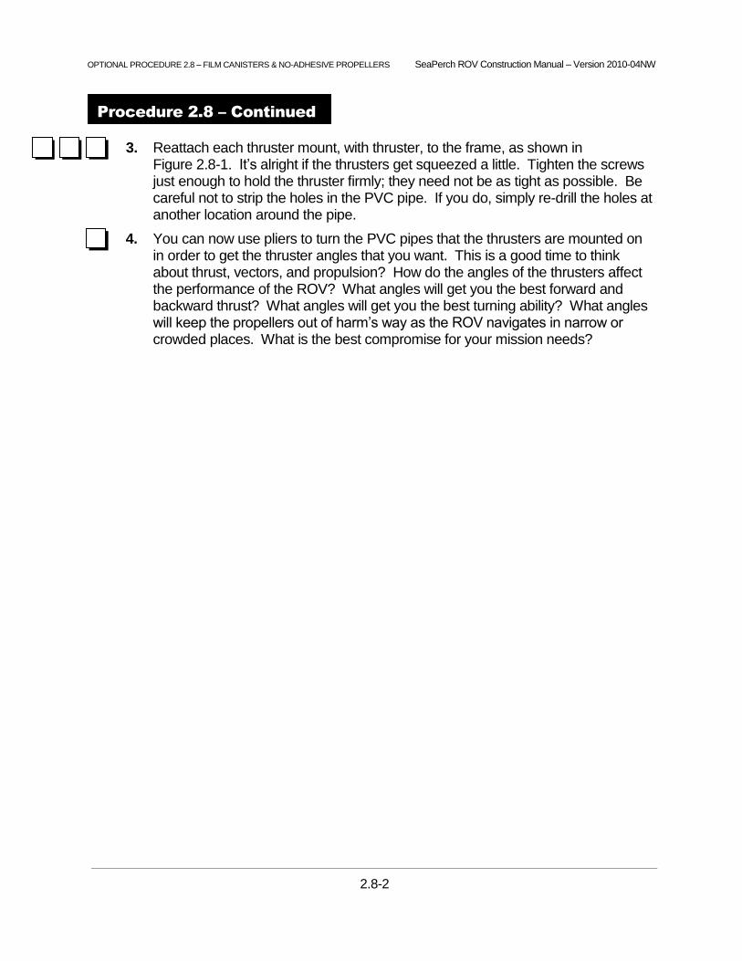
OPTIONAL PROCEDURE 2.8 – FILM CANISTERS & NO-ADHESIVE PROPELLERS SeaPerch ROV Construction Manual – Version 2010-04NW
2.8-2
3. Reattach each thruster mount, with thruster, to the frame, as shown in Figure 2.8-1. It’s alright if the thrusters get squeezed a little. Tighten the screws just enough to hold the thruster firmly; they need not be as tight as possible. Be careful not to strip the holes in the PVC pipe. If you do, simply re-drill the holes at another location around the pipe.
4. You can now use pliers to turn the PVC pipes that the thrusters are mounted on in order to get the thruster angles that you want. This is a good time to think about thrust, vectors, and propulsion? How do the angles of the thrusters affect the performance of the ROV? What angles will get you the best forward and backward thrust? What angles will get you the best turning ability? What angles will keep the propellers out of harm’s way as the ROV navigates in narrow or crowded places. What is the best compromise for your mission needs?
Procedure 2.8 – Continued

SeaPerch ROV Construction Manual – Version 2010-04NW
2.9-1
Procedure 2.9 – Waterproof and Mount the Tether Cable
Tools:
#2 Phillips Screwdriver
Pliers
Flush Wire-Cutting Pliers
Materials:
Completed Frame with Thrusters Mounted
1” (2.5 cm) Butyl Rubber Tape
Electrical Tape
5 6” or 8" Tie Wraps
Figure 2.9-1: Tether Cable Tied in a Strain Relief Loop
and Pointing Straight Back from the Center of the ROV
Construction Steps:
1. Locate the point near the thruster end of the tether cable where the four thruster wire pairs emerge from the cable sheath, and bring it out a bit away from the vehicle frame so you can waterproof that opening using butyl rubber tape.
2. Locate in your kit (or cut from a roll) a 1” (2.5 cm) piece of butyl rubber tape.
3. Stretch the tape to about twice its relaxed length, then wind it among and around the four wire pairs where they emerge from the cable's outer sheath and press it over the sheath opening such that it extends at least ½” on each side of the opening, as shown in Figure 2.9-2. Knead and work it in between the wires well, so that it seals both around and between the wires and forms a smooth seal over the sheath opening, preventing water from getting into the tether cable.
4. Wrap electrical tape over the butyl rubber tape to keep it from sticking to anything.
Figure 2.9-2. Butyl Rubber Tape Wrap to Waterproof Tether Cable Sheath Opening

SeaPerch ROV Construction Manual – Version 2010-04NW
2.9-2
5. After waterproofing the tether cable, make a loose knot loop in the cable and attach it to the vehicle frame and the payload net with tie wraps in at least two places, as shown in Figure 2.9-1. This “strain relief” loop is intended to prevent any pulling on the tether cable from pulling on the thruster wires.
6. Install two crossed tie wraps over the tether cable where it passes over the center of the pipe at the rear of the ROV, as shown in Figures 2.9-1 and 2.9-3. This is important to keep the tether cable pointing straight back from the ROV so that its drag in the water does not tend to pull the ROV more to one side than the other, making it more difficult to turn the ROV in one direction compared to the other.
7. Pull all tie wraps tight with pliers, and then use the flush wire-cutting pliers to trim the ends flush. Coil the brown wire pair out of the way and tie-wrap it to the payload net; it may be needed later for accessories or for a thruster wire repair.
This completes assembly of your SeaPerch ROV Thrusters!
Figure 2.9-3. Crossed Wire Ties Keep the Tether Centered on the Rear of the ROV
Procedure 2.9 – Continued

3.0-1
SeaPerch Program Office
The Society of Naval Architects and Marine Engineers
601 Pavonia Avenue
Jersey City, New Jersey 07306
Version 2010-04NW
Unit 3
SeaPerch
Remotely Operated Vehicle (ROV)
Assembly of Subsystem Three
The Control Box
August 2010
The SeaPerch educational program was created by Harry Bohm and Vickie Jensen and published in their 1997 book "Build Your Own Underwater Robot and Other Wet Projects." The initial curriculum was developed by the Massachusetts Institute of Technology, and this version of the SeaPerch Construction Manual was provided under the Office of Naval Research National Naval Responsibility for Naval Engineering (NNRNE) Outreach initiative.

OPTIONAL PROCEDURES – THREE TOGGLE SWITCHES SeaPerch ROV Construction Manual – Version 2010-04NW
3.0-2
Unit Assembly of Subsystem Three
The Control Box 3
Tools and Materials Needed
Tools Materials
Eye Protection (Always Worn)
Hand Drill or Drill Press
¼” Drill Bit
Pliers
Wire Stripper
Flush Wire-Cutting Pliers
Marking Pen (or Pencil)
Ruler
Scissors
Soldering Iron and Solder
#2 Phillips Screwdriver
Vise or Clamp
Completed Vehicle Frame with Thrusters Installed
1 Control Box
6’ (~2 m) #18 Speaker Wire (Or Lamp Cord)
24” (61 cm) #22 Stranded Hook-Up Wire, Red
24” (61 cm) #22 Stranded Hook-Up Wire, Black
2 Quick-Disconnect Terminals
1 Fuse Holder and 10 Amp Slow-Blow Fuse
1 12 Volt Battery
1 Double-Pole, Double-Throw (DPDT), Center-Off, Toggle Switch (Non-Momentary Type Preferred)
2 Double-Pole, Double-Throw (DPDT), Center-Off, Toggle Switches (Momentary Type Preferred)
Electrical tape
Time Needed to Complete Unit 3
Total Construction Time:
Unit 3 usually requires about 7 hours to complete. More time should be allowed if the class is building a large number of ROVs.
Typical Allocation of Class Periods:
For standard class periods of approximately 50 minutes each, including any necessary clean-up time, plan for at least seven periods to complete this unit.
1 period to gather parts and prepare the control box (ergonomic design).
2 periods to make the power cable.
3 periods (often more) to wire the toggle switches.
1 period to finish the control box.

OPTIONAL PROCEDURES – THREE TOGGLE SWITCHES SeaPerch ROV Construction Manual – Version 2010-04NW
3.0-3
SeaPerch Electrical Circuit Diagram
In this unit, you will build the control box for your SeaPerch ROV. Below is a circuit diagram (or “schematic”) which shows all the electrical connections that will be made. This diagram is a technical representation to show the components and how they are connected, but is not drawn to scale, and it leaves out everything but the wires and electrical components. You can always refer back to this diagram to understand how and why the wiring should work. The individual procedures have their own circuit diagrams, which are simply parts of this complete diagram. They also have wiring diagrams, which will help you understand what the wiring should actually look like.
Figure 3.0-1: SeaPerch ROV Circuit Diagram
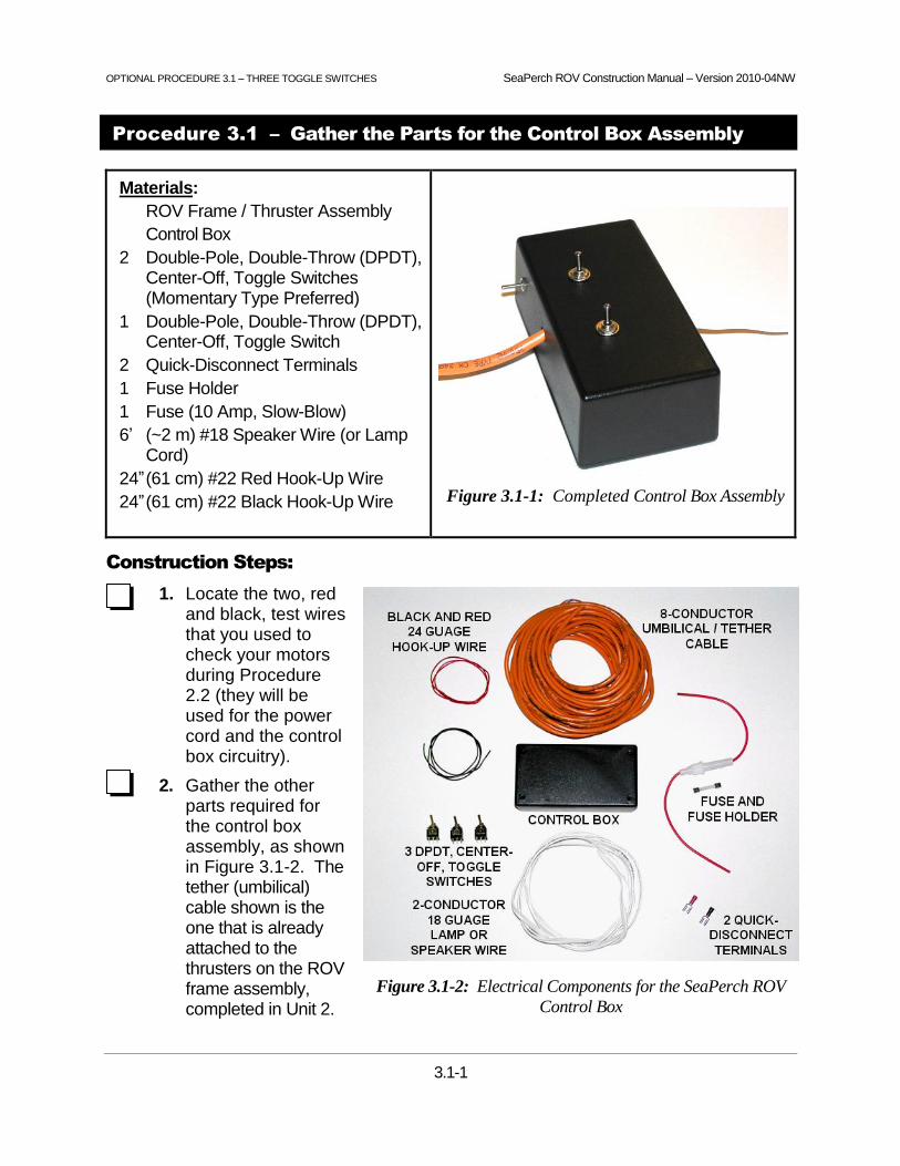
OPTIONAL PROCEDURE 3.1 – THREE TOGGLE SWITCHES SeaPerch ROV Construction Manual – Version 2010-04NW
3.1-1
Figure 3.1-2: Electrical Components for the SeaPerch ROV
Control Box
Procedure 3.1 – Gather the Parts for the Control Box Assembly
Materials:
ROV Frame / Thruster Assembly
Control Box
2 Double-Pole, Double-Throw (DPDT), Center-Off, Toggle Switches (Momentary Type Preferred)
1 Double-Pole, Double-Throw (DPDT), Center-Off, Toggle Switch
2 Quick-Disconnect Terminals
1 Fuse Holder
1 Fuse (10 Amp, Slow-Blow)
6’ (~2 m) #18 Speaker Wire (or Lamp Cord)
24” (61 cm) #22 Red Hook-Up Wire
24” (61 cm) #22 Black Hook-Up Wire
Figure 3.1-1: Completed Control Box Assembly
Construction Steps:
1. Locate the two, red and black, test wires that you used to check your motors during Procedure 2.2 (they will be used for the power cord and the control box circuitry).
2. Gather the other parts required for the control box assembly, as shown in Figure 3.1-2. The tether (umbilical) cable shown is the one that is already attached to the thrusters on the ROV frame assembly, completed in Unit 2.


OPTIONAL PROCEDURE 3.2 – THREE TOGGLE SWITCHES SeaPerch ROV Construction Manual – Version 2010-04NW
3.2-1
Figure 3.2-2: Typical Control Box Hole Locations
Procedure 3.2 – Prepare the Control Box
Tools:
#2 Phillips Screwdriver
Drill (or Drill Press)
¼” Drill Bit
Marker (or Pencil)
Ruler
Vise or Clamp
Materials:
Control Box
Electrical Tape
Figure 3.2-1: Typical Control Box Before Assembly
Construction Steps:
1. Locate the control box, shown in Figure 3.2-1. Be careful not to lose the small lid screws during the assembly process.
2. Using the marker, or a pencil, mark the locations of the holes on the control box, as shown in Figure 3.2-2. There should be one hole in the back for the power cord to come in, one in the center of the front for the tether cable to go out, one on the far right (or left) side of the front for the vertical thruster control switch, and two on top (note: this is not the box’s lid, which will become the bottom of the control box) for the horizontal thruster control switches. Plan the layout carefully so that the switches (and their wires) don’t interfere with each other or with internal parts of the box.
OPTIONAL PROCEDURE 3.2 – THREE TOGGLE SWITCHES SeaPerch ROV Construction Manual – Version 2010-04NW
3.2-2
3. Check the diameters of the threaded mounting shafts of the switches. If any require a mounting hole smaller or larger than the usual ¼” holes called for in these instructions, you may need to use a different drill bit.
4. Secure the control box in a vise or clamp (but not too tightly), and drill holes in the locations marked using a ¼” (or other appropriate size) drill bit. Don’t drill while holding the box in your hand! After drilling, clear the holes of any burrs or loose plastic debris from the drilling process.
Procedure 3.2 – Continued

OPTIONAL PROCEDURE 3.3 – THREE TOGGLE SWITCHES SeaPerch ROV Construction Manual – Version 2010-04NW
3.3-1
Figure 3.3-2: Power Cord Wiring Diagram
Quick
Disconnect
Terminal on
Positive
Battery Tab
Quick
Disconnect
Terminal on
Negative
Battery Tab
+– Quick
Disconnect
Terminal on
Positive
Battery Tab
Quick
Disconnect
Terminal on
Negative
Battery Tab
+–
Procedure 3.3 – Assemble the Power Cord
Tools:
Soldering Iron and Solder
Flush Wire-Cutting Pliers
Wire Strippers
#2 Phillips Screwdriver
Scissors
Pliers
Materials:
6’ #18 Speaker Wire or Lamp Cord
2 Quick-Disconnect Terminals
Fuse Holder
24” (61 cm) Red #22 Hook-Up Wire
24” (61 cm) Black #22 Hook-Up Wire
1 DPDT, Center-Off, Toggle Switch
2 DPDT, Center-Off, Toggle Switches (Momentary-Contact Preferred)
Electrical Tape
Figure 3.3-1: Completed Power Cord
Assembly Installed in the Control Box
NOTE: In this step you will build the power cord for your SeaPerch ROV, as shown in Figure 3.3-1. A wiring diagram of the power cord is show in Figure 3.3-2.
Construction Steps:
1. Cut the #22 red and black wires into three equal-length pieces (three black and three red). If any of your pieces will be less than 5” (13 cm), ask your teacher for extra wire.
2. Strip just ¼” (6 mm) of insulation from one end of each piece of wire and about ½” (13 mm) from their other ends. Twist the inner wires (strands) on both ends of each wire to prevent fraying or breaking.

OPTIONAL PROCEDURE 3.3 – THREE TOGGLE SWITCHES SeaPerch ROV Construction Manual – Version 2010-04NW
3.3-2
3. Gather the ½” stripped ends of the three red wires and twist them all together, as shown in Figure 3.3-3.
4. Do the same with the three black wires. These spliced wire bundles will distribute power in your control box.
5. Find the power cord wire (#18 speaker wire or lamp cord), and determine which
of its two conductors will be positive and which will be negative. To do this, note that each conductor has its own insulation, and that the two are attached to each other with a thin web of insulation material. Usually the insulation on one conductor is ribbed (like corduroy), and the other is smooth. Sometimes, one conductor's insulation is instead marked with white or black stripes, printed information, or other polarity indicators. For some power cords, the insulation is clear but one conductor is silver and the other is copper. For this project, we will call the ribbed, marked, or copper side the positive (+) side, and the smooth, unmarked, or silver side the negative (–) side.
6. On each end of the power cord wire, carefully separate the two conductors for about 1” (2.5 cm). This is best done by snipping the thin web of plastic between the wires with a small pair of scissors, or a small pair of wire cutters. Be careful not to nick the insulation on either of the individual conductors.
7. On one end of the power cord wire, leave the separated section only 1” (2.5 cm) long. On the other end, pull or cut the two conductors apart for about 14” (35 cm). On the end of the wire that you just separated, find the positive (ribbed or marked) side, and cut off 13” (33 cm) of that conductor. This section will be replaced with the fuse holder, as shown in Figure 3.3-1.
8. Strip 1/2” (13 mm) of insulation off both of the fuse holder wires. The fuse holder does not have a positive and negative side; it will work either way.
9. Strip 1/2” (13 mm) of insulation off of all four ends of the power cord wire. Twist the strands together on the ends of each conductor to prevent fraying and breaking.
Procedure 3.3 – Continued
Figure 3.3-3: Spliced Power Wire Bundles

OPTIONAL PROCEDURE 3.3 – THREE TOGGLE SWITCHES SeaPerch ROV Construction Manual – Version 2010-04NW
3.3-3
10. Attach the fuse holder wire to the positive (ribbed / marked / copper) side of the power cord wire, where you previously cut off the 13” (33 cm) piece. Twist the wires tightly together (in-line, as shown in Figure 3.3-4), solder the connection, and cover it with electrical tape.
11. Slide the “+” quick-disconnect terminal onto the loose end of the fuse holder wire, and crimp it firmly using a crimping tool or pliers. You may solder this connection if it appears to be loose after crimping; however, try not to overheat the terminal’s colored, identifying insulation.
12. Slide the “–” quick-disconnect terminal onto the negative side of the power cord, and crimp it (and optionally solder it) as above. Use a black permanent marking pen to color the insulator (usually pink) of this terminal black, indicating negative polarity. At this point, the end of your power cable should look like Figure 3.3-5..
13. Pass the loose end of the power cable (no fuse holder) through the hole in the back of your control box, from the outside. Tie a strain-relief knot about 6” (15 cm) up the cord on the inside of the control box, as shown in Figures 3.3-1 and 3.3-6.
Figure 3.3-4: Battery End of the Power Cord During Assembly
Figure 3.3-5: Completed Battery End of the Power Cord
Procedure 3.3 – Continued

OPTIONAL PROCEDURE 3.3 – THREE TOGGLE SWITCHES SeaPerch ROV Construction Manual – Version 2010-04NW
3.3-4
14. Take the spliced bundle of three red “+” wires, and twist the bundled end onto the wire from the positive (ribbed / marked / copper) side of the speaker wire. Take the spliced bundle of three black “–” wires and twist the bundled end onto the wire from the negative (smooth / unmarked / silver) side of the power cord. Solder the two connections, and cover them each, separately, with electrical tape, as shown in Figure 3.3-7. Figure 3.3-1 shows the completed power cord assembly installed in the control box.
Figure 3.3-6: Power Cord Strain-Relief Knot in Control Box
Figure 3.3-7: Wire Bundles Soldered to Control Box End of the Power Cord
~6” Length, Beyond Knot
Procedure 3.3 – Continued

OPTIONAL PROCEDURE 3.3 – THREE TOGGLE SWITCHES SeaPerch ROV Construction Manual – Version 2010-04NW
3.3-5
NOTE: In order to stabilize the switches during the wiring process, when a bench vise is not available, the control box may be used as a temporary switch holder, by mounting the switches “inside-out,” as shown in Figure 3.3-8. The following steps in Procedure 3.3 are optional, but they will help you to complete the wiring quickly and easily and help to keep the wiring well organized, which will simplify any later repair work, if needed.
Figure 3.3-8: Control Box Used as a Temporary Switch Wiring Fixture
15. Remove the mounting hardware from each of the switches, taking care not to misplace the small nuts and washers.
16. Temporarily install the two horizontal thrusters’ toggle switches (momentary contact type, if available) in the top of the control box, and the vertical thruster’s toggle switch (usually a non-momentary contact type) in the front, all in their intended locations but with the switch bodies on the outside of the box. Secure the switches with just one of their respective mounting nuts, placed snugly on the inside of the box. Use pliers (standard type, not needle-nose pliers) to tighten the nuts enough to prevent the switches from spinning in their mounting holes as the box is handled and during soldering activities (having stable switches is important for easy soldering).
17. Place the remaining switch-mounting hardware items onto the adhesive side of a piece of electrical tape, and then stick the tape onto the side of the control box, to keep the small parts from getting misplaced during the wiring process.
Procedure 3.3 – Continued


OPTIONAL PROCEDURE 3.4 – THREE TOGGLE SWITCHES SeaPerch ROV Construction Manual – Version 2010-04NW
3.4-1
Procedure 3.4 – Wire the Vertical Thruster Control Switch
Tools:
Soldering Iron and Solder
Small Needle-Nose Pliers
Flush Wire-Cutting Pliers
Wire Strippers
Vise or Clamp
Materials:
Control Box with Assembled Power Cord
Tether Cable (Loose End)
1 DPDT, Center-Off (Non-Momentary) Toggle Switch
Figure 3.4-1: Vertical Thruster Toggle Switch with
Tether Cable and Power Wires Connected
Switch Soldering Tips:
When soldering the switches, be very careful to avoid shorting out the many wires which end up in close proximity at the backs of the switches. Always check the wiring for correctness before soldering; although possible, it is not easy to make corrections later. When connecting wires to switch terminals, make sure that the individual wire strands are well twisted together, to avoid having frayed strands that may short out against other wires or terminals. Solder quickly, so that the wires do not get too hot and melt their insulation (or parts inside the switch!). Waiting about a half minute before soldering another terminal on the same switch will allow the switch to cool down. Keep the stripped part of the wires short (~1/4”). Bend the wires through switch terminals carefully and squeeze them into place with needle-nose pliers. Make a good mechanical connection before you solder. Use just a little solder. Using too much solder can cause the excess to stick out and touch other connections. Always wear safety glasses when soldering!
Construction Steps:
1. Review Figures 3.4-1, 3.4-2, and 3.4-3 to understand the wiring and functions of the vertical thruster control (“up / down” toggle switch).
2. Push the loose end of the tether cable (after first grouping the loose wire pairs into a small bundle) through the hole into the front of the control box, entering from the outside. Tie a strain-relief knot about 11” (28 cm) from the ends of the wires, inside the box. Don’t pull the knot too tight (about ¾” diameter is fine.) IMPORTANT: This step can be rather easy to accidentally skip; be sure to do it before wiring the switch connections!
3. Strip additional sheath from the tether cable to expose about 9” (23 cm) of the wire pairs, being very careful not to nick the insulation on the inner wires.

OPTIONAL PROCEDURE 3.4 – THREE TOGGLE SWITCHES SeaPerch ROV Construction Manual – Version 2010-04NW
3.4-2
Procedure 3.4 – Continued
Figure 3.4-2: Vertical Thruster Control Circuit Diagram
Figure 3.4-3: Vertical Thruster Wiring Diagram
“Crisscross” Wires Used to Reverse Polarity

OPTIONAL PROCEDURE 3.4 – THREE TOGGLE SWITCHES SeaPerch ROV Construction Manual – Version 2010-04NW
3.4-3
4. Separate the four twisted wire pairs (if the wires do not come already twisted into pairs, you should twist the matching colored wires together).
5. Refer to Figures 3.4-1 and 3.4-2 and examine the vertical toggle switch. Note that there are six terminals, three on each side. (Each side operates like a separate “single-pole, double-throw” (SPDT) toggle switch, but the two sides are “thrown” at the same time when you flip the switch.) You will be attaching the “+” and “–” power wires to the center terminals of the switch, and attaching the motor wires (from the tether cable) to the bottom two terminals (you can select either end of the switch to be the “bottom”). When the switch is thrown to make connections between the center two terminals and the bottom terminals, the motor will run to apply thrust in the “down” direction. In order to reverse the polarity (and thus the direction of the thruster), you will also install two “crisscross” wires from the two terminals on the bottom end of the switch to the two on the top end (crossing them to reverse the polarity). Thus, when the switch is thrown to make the opposite connections, the motor will run in the other direction, applying “upward” thrust.
6. A short length of the tether cable wires will be used to make the crisscross wires for the toggle switches. Unwrap the tether wires, and cut 2” (5 cm) from ends of the orange, green, and blue pairs. Do not cut the brown wire pair; it may be needed for a future use.
7. You will be connecting the orange pair (the orange and the white & orange striped wires) for the vertical control switch, so set the blue and green pairs aside for now. Separate the orange crisscross wire pair and strip 1/8” to 1/4" (3-6 mm) of insulation off of each end of both wires.
8. Secure the vertical toggle switch (or the whole control box if it is being used as a switch wiring fixture, which can also be taped down on a tabletop for stability) in a clamp or a vise so that it will be held in a stable position while you connect and solder the wires.
9. Pick any one of the three red (+) wires from your power cord (inside the control box), and insert it through the left center terminal on the toggle switch, being careful to have all of the small strands of wire pass through the hole in the terminal. Then bend the strands around the terminal and squeeze them tight using needle-nose pliers, to make a good mechanical connection, in preparation for soldering.
10. Similarly, insert one of the black (–) power wires into the right center terminal on the toggle switch, and again bend and squeeze the wire tightly to the terminal.
11. Once you have attached both wires to the switch, STOP and ask your teacher or an adult classroom assistant to check your connections, as it’s much easier to make corrections before you solder.
Procedure 3.4 – Continued

OPTIONAL PROCEDURE 3.4 – THREE TOGGLE SWITCHES SeaPerch ROV Construction Manual – Version 2010-04NW
3.4-4
12. Using a well-heated soldering iron, with a clean, freshly “tinned” tip, solder just the red-wire (left, center) terminal on the switch, being careful not to use too much solder (use just enough to flow over the connection) or to overheat the switch (which could melt internal components, permanently damaging the switch). For this and all other soldered connections, also be careful not to create any solder bridges between the terminals, and make sure to snip off any frayed pieces of wire sticking out toward other terminals on the switch.
13. Wait at least 30 seconds for the switch to cool, and then solder the black-wire (right, center) terminal on the switch.
14. Connect one end of the 2” (5 cm) white & orange striped crisscross wire to the top left terminal of the switch, bending it around the terminal as before, and similarly connect the other end of the wire to the bottom right terminal. Do not solder them yet.
15. Connect one end of the orange crisscross wire to the top right terminal of the switch, and connect the other end to the bottom left terminal. Do not solder them yet.
16. Check to make sure that all four connections are tight and that the wires are out of the way of the other terminals, and then solder only the top two connections, allowing about 30 seconds between soldering operations. Figure 3.4-4 shows how these two connections should look at this point in the process.
Figure 3.4-4: Power and “Crisscross” Connections on a DPDT Toggle Switch
17. Find the orange wire pair from the tether cable and untwist its wires for about 1" (2.5 cm). Strip 1/8” to 1/4" (3 to 6 mm) of insulation off the end of both the orange wire and the white & orange striped wire. Be careful not to nick the wires (which could cause them to break off later).
POWER WIRES
SOLDERED ONTO
CENTER TWO
TERMINALS
CRISSCROSS WIRES
SOLDERED ONTO “TOP
TWO” TERMINALS
ONLY, AS SHOWN IN
FIGURE 3.4-3
BOTTOM TWO
WIRES NOT SOLDERED YET
Procedure 3.4 – Continued

OPTIONAL PROCEDURE 3.4 – THREE TOGGLE SWITCHES SeaPerch ROV Construction Manual – Version 2010-04NW
3.4-5
18. Insert the orange wire from the tether cable into the bottom left terminal on the toggle switch (on the side that has the red wire on the center terminal), adding it to the orange wire already in place on that terminal, as shown in Figure 3.4-3. Bend and squeeze the wire to the terminal as before. Make sure that no other terminal is touched by the orange wires. When you have the two wires firmly attached to this terminal, STOP and ask your teacher or an adult classroom assistant to check your wiring before you solder the connection.
19. Solder the two wires on the bottom left terminal.
20. Insert the white & orange striped wire from the tether cable into the bottom right terminal (the one that already has a white & orange wire), again bending, squeezing it to the terminal, and checking the connection. Solder the two wires on this terminal.
21. Check all terminals on the switch to make sure that there are no stray wire strands or solder bridges between the terminals. The wired switch should look similar to the one shown in Figure 3.4-1.
22. Remove the switch (or control box) from the clamp or vise. If the switch was mounted on the outside of the control box (to use it as a switch wiring fixture), remove its nut from the inside of the box, and remove the switch from the box.
23. Carefully install the switch in its mounting hole from the inside of the control box, orienting it so that the wires from the tether cable are nearest the open bottom of the box. Install the lock washer and tighten the nut so that the switch will not easily rotate in the box.
24. Route the wires neatly along the inside of the box, out of the way of the locations for the other switches (yet to be wired and installed). The result should appear similar to Figure 3.4-5.
Figure 3.4-5: Vertical Thruster Switch Wired and Installed in the Control Box
Procedure 3.4 – Continued

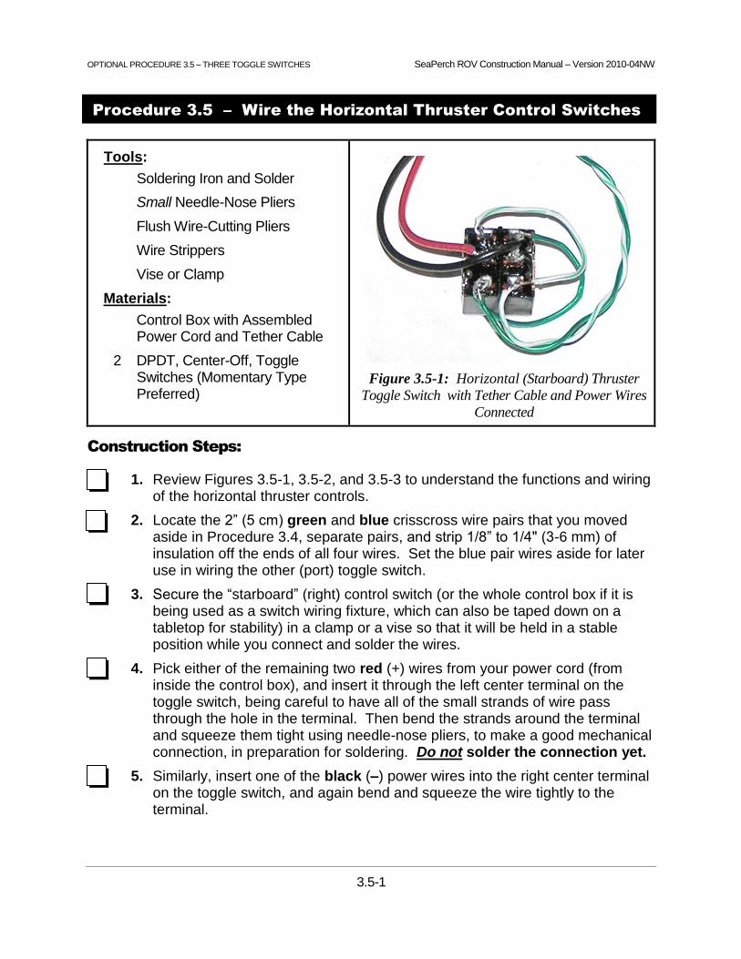
OPTIONAL PROCEDURE 3.5 – THREE TOGGLE SWITCHES SeaPerch ROV Construction Manual – Version 2010-04NW
3.5-1
Procedure 3.5 – Wire the Horizontal Thruster Control Switches
Tools:
Soldering Iron and Solder
Small Needle-Nose Pliers
Flush Wire-Cutting Pliers
Wire Strippers
Vise or Clamp
Materials:
Control Box with Assembled Power Cord and Tether Cable
2 DPDT, Center-Off, Toggle Switches (Momentary Type Preferred)
Figure 3.5-1: Horizontal (Starboard) Thruster
Toggle Switch with Tether Cable and Power Wires
Connected
Construction Steps:
1. Review Figures 3.5-1, 3.5-2, and 3.5-3 to understand the functions and wiring of the horizontal thruster controls.
2. Locate the 2” (5 cm) green and blue crisscross wire pairs that you moved aside in Procedure 3.4, separate pairs, and strip 1/8” to 1/4" (3-6 mm) of insulation off the ends of all four wires. Set the blue pair wires aside for later use in wiring the other (port) toggle switch.
3. Secure the “starboard” (right) control switch (or the whole control box if it is being used as a switch wiring fixture, which can also be taped down on a tabletop for stability) in a clamp or a vise so that it will be held in a stable position while you connect and solder the wires.
4. Pick either of the remaining two red (+) wires from your power cord (from inside the control box), and insert it through the left center terminal on the toggle switch, being careful to have all of the small strands of wire pass through the hole in the terminal. Then bend the strands around the terminal and squeeze them tight using needle-nose pliers, to make a good mechanical connection, in preparation for soldering. Do not solder the connection yet.
5. Similarly, insert one of the black (–) power wires into the right center terminal on the toggle switch, and again bend and squeeze the wire tightly to the terminal.

OPTIONAL PROCEDURE 3.5 – THREE TOGGLE SWITCHES SeaPerch ROV Construction Manual – Version 2010-04NW
3.5-2
Figure 3.5-2: Horizontal Thruster Control Circuit Diagram
Figure 3.5-3: Horizontal Thruster Control Toggle Switch Wiring Diagram
Procedure 3.5 – Continued

OPTIONAL PROCEDURE 3.5 – THREE TOGGLE SWITCHES SeaPerch ROV Construction Manual – Version 2010-04NW
3.5-3
6. Using a well-heated soldering iron, with a clean, freshly “tinned” tip, solder just the red-wire (left, center) terminal on the switch, being careful not to use too much solder (use just enough to flow over the connection) or to overheat the switch (which could melt internal components, permanently damaging the switch). For this and all other soldered connections, also be careful not to create any solder bridges between the terminals, and make sure to snip off any frayed pieces of wire sticking out toward other terminals on the switch.
7. Wait at least 30 seconds for the switch to cool, and then solder the black-wire (right, center) terminal on the switch.
8. Connect one end of the 2” (5 cm) green & white striped crisscross wire to the top left terminal of the switch, bending it around the terminal as before, and similarly connect the other end of the wire to the bottom right terminal. Do not solder the connections yet.
9. Connect one end of the green crisscross wire to the top right terminal of the switch, and connect the other end to the bottom left terminal. Do not solder the connections yet.
10. Check to make sure that all four connections are tight and that the wires are out of the way of the other terminals, and then solder only the top two connections, allowing about 30 seconds between soldering operations.
11. Take the tether cable’s green wire pair and untwist it for about 1” (2.5 cm). Strip 1/8” to 1/4" (3 to 6 mm) of insulation off the ends of both the green wire and the white & green striped wire. Be careful not to nick the wires (which could cause them to break off later).
12. Insert the green wire into the bottom left terminal on the toggle switch (on the side that has the red wire on the center terminal), adding it to the green wire already in place on that terminal, as shown in Figures 3.5-1 and 3.5-3. Bend and squeeze the wire to the terminal as before. Make sure that no other terminal is touched by the green pair wires.
13. Solder the two wires on the bottom left terminal.
14. Insert the white & green striped wire from the tether cable into the bottom right terminal (the one that already has a white & green striped wire connected), again bending, squeezing it to the terminal, and checking the connection. Solder the two wires on this terminal.
15. Check all terminals on the switch to make sure that there are no stray wire strands or solder bridges between the terminals. The wired switch should look similar to the one shown in Figure 3.5-1.
Procedure 3.5 – Continued

OPTIONAL PROCEDURE 3.5 – THREE TOGGLE SWITCHES SeaPerch ROV Construction Manual – Version 2010-04NW
3.5-4
16. Insert the remaining red (+) wire from your power cord through the left center terminal on the “port” (left) toggle switch, again being careful to have all of the small strands of wire pass through the hole in the terminal. Bend the strands around the terminal and squeeze them tight using needle-nose pliers as before, to make a good mechanical connection, in preparation for soldering.
17. Insert the remaining black (–) power wire into the right center terminal on the toggle switch, and again bend and squeeze the wire tightly to the terminal.
18. Using a well-heated soldering iron, with a clean, freshly “tinned” tip, solder just the red-wire (left, center) terminal on the switch.
19. Wait at least 30 seconds for the switch to cool, and then solder the black-wire (right, center) terminal on the switch.
20. Locate the 2” (~5 cm) pieces of wire from the blue wire pair that you cut and set aside earlier, for the crisscross wires for this toggle switch.
21. Connect one end of the white & blue striped crisscross wire to the top left terminal of the switch, bending it around the terminal as before, and similarly connect the other end of the wire to the bottom right terminal. Do not solder them yet.
22. Connect one end of the blue crisscross wire to the top right terminal of the switch, and connect the other end to the bottom left terminal. Do not solder them yet.
23. Check to make sure that all four connections are tight and that the wires are out of the way of the other terminals, and then solder only the top two connections, allowing about 30 seconds between soldering operations.
24. Now take the blue pair from the umbilical / tether cable and untwist the pair for about 1” (2.5 cm). Strip 1/8” to 1/4" (3 to 6 mm) of insulation off the end of both the blue wire and the white & blue striped wire. Again, be careful not to nick the wires.
25. Insert the blue wire into the bottom left terminal on the toggle switch, adding it to the blue wire already in place on that terminal, as shown in Figure 3.5-3. Bend and squeeze the wire to the terminal as before.
26. Solder the two wires on the bottom left terminal.
27. Insert the white & blue striped wire into the bottom right terminal (the one that already has a white & blue wire), again bending, squeezing it to the terminal, and checking the connection. Solder the two wires on this terminal.
Procedure 3.5 – Continued

OPTIONAL PROCEDURE 3.5 – THREE TOGGLE SWITCHES SeaPerch ROV Construction Manual – Version 2010-04NW
3.5-5
28. Check all terminals on the switch to make sure that there are no stray wire strands or solder bridges between the terminals. The wired switch should look like the other horizontal thruster switch, similar to the one shown in Figure 3.5-1 (but with blue-pair wire colors). If using the control box as a switch wiring fixture, the completed switches should look similar to those shown in Figure 3.5-4.
Figure 3.5-4: Completed Wiring for the Horizontal Thruster Control Switches
Procedure 3.5 – Continued


OPTIONAL PROCEDURE 3.6 – THREE TOGGLE SWITCHES SeaPerch ROV Construction Manual – Version 2010-04NW
3.6-1
Procedure 3.6 – Finish the Control Box
Tools:
Pliers
#2 Phillips Screwdriver
Materials:
Control Box with Wired Switches
Control Box Cover
4 Control Box Cover Screws
Switch Mounting Hardware
Figure 3.6-1: Completed Control Box
Construction Steps:
1. If the control box was used as a temporary switch wiring fixture, carefully remove the switches that are mounted on the outside of the box.
2. Place the toggle switches in their intended holes inside the control box, as shown in Figure 3.6-1. Orient them such that the ends with the tether wires connected are nearest the back (power cable side) of the box. Turn them until straight and parallel, install the lock-washers and nuts, and carefully tighten them into place with pliers (needle-nose pliers do not work well for this). Make sure that the toggle switches are mounted tightly so that they will not twist during use.
3. Route the wires neatly in the box as shown in Figure 3.6-2. You will find that re-adjusting the strain relief knots on the power cord and tether cable to push excess cable back out of the box will help you to fit the wiring inside more neatly.
Figure 3.6-2: Control Box with All Switches Installed and Wires Routed Neatly

OPTIONAL PROCEDURE 3.6 – THREE TOGGLE SWITCHES SeaPerch ROV Construction Manual – Version 2010-04NW
3.6-2
4. Ask the teacher or an adult volunteer to check the wiring, and then screw the cover onto the control box using the Phillips screwdriver and the screws provided.
5. Place the fuse in the fuse holder, if it is not already in place, but do not connect the battery until the testing in the following section has been completed.
A completed ROV system is shown in Figure 3.6-3.
CONGRATULATIONS, you have finished the construction of your SeaPerch ROV!
Now it’s time to get it ballasted and tested!
Figure 3.6-3: Completed SeaPerch ROV System, Ready for Testing and Ballasting
Procedure 3.6 – Continued

SeaPerch ROV Construction Manual – Version 2010-04NW
T-1
Testing and Ballasting the ROV
Time Needed to Complete Testing and Ballasting of the ROV
Combined Testing and Ballasting Time:
Initial electrical testing usually requires much less than 1 hour, unless the vehicle does not function properly, in which case several hours may be required to resolve the problem(s). Ballasting experimentation and mounting of the final ballast weights usually requires about 1 to 2 hours. With large numbers of ROVs, more time should be allowed if in-water test space and troubleshooting resources are limited.
Typical Allocation of Class Periods:
For standard class periods of approximately 50 minutes each, including any necessary clean-up time, plan for at least four periods to test the ROVs and ready them for in-water use.
1 period to perform initial electrical tests, check the operation of the thrusters and control box, and make minor adjustments.
2 periods to review buoyancy concepts (conducting a hands-on “buoyancy lab” session is recommended), determine the amount of ballast needed, and install the weights.
1 class period for troubleshooting and problem solving, which is usually needed for at least a few ROVs per class.
Initial Electrical Testing
Testing Before Connecting the Battery:
Conducting a few quick short-circuit tests before connecting the ROV to the battery can prevent a blown fuse, should there be an undetected problem with the ROV’s wiring. The following tests are recommended.
Open-Switch Test:
Connect an ohmmeter (multi-meter) or continuity tester across the two power cord wires, where the battery would normally be connected. With all switches in the “off” position, there should be no continuity indicated, and an ohmmeter should read infinite resistance. If there is a continuity indication or if any less than infinite resistance is measured, there is a short circuit somewhere in the wiring, likely in the control box. Solve this problem before connecting to the battery, or the fuse will likely blow.

SeaPerch ROV Construction Manual – Version 2010-04NW
T-2
Closed-Switch Tests:
With the continuity tester or meter connected, close each switch, one at a time, to check for continuity through the thrusters. A typical thruster has some electrical resistance, but little enough to allow a continuity tester to indicate continuity. An ohmmeter should show a relatively low resistance, typically from about 10 to 50 ohms. Conduct this test for each pushbutton switch (if used) and for the two “on” throw positions of each toggle switch. If the resistance reads near zero on an ohmmeter, that indicates either a shorted thruster or another short-circuit wiring problem in the control box or tether cable. Solve the problem before connecting power to the ROV.
Testing for Proper Thruster Operation:
After passing the tests above, it is time to connect the ROV to its battery. Connect the two power leads (the alligator clips or the quick-disconnect terminals) to the appropriate positive and negative terminals of the battery. Then, close each switch, one at a time, for each pushbutton switch (if used) and for each throw direction of the toggle switches. The propellers should spin counter-clockwise (looking into the end of the shaft) when the controls are switched to the “forward” position for the horizontal thrusters and for the “down” position of the vertical thruster. If any thruster spins in the wrong direction or does not spin properly, see Appendix A, “Troubleshooting Your SeaPerch ROV” for some common solutions. Students should try to solve the problems on their own before using that aid, at least until running out of ideas!
Ballasting and Trimming the ROV
Understanding Neutral Buoyancy:
ROVs work best when they are nearly neutrally buoyant, with a slight positive buoyancy to enable them to slowly return to the surface should they fail. An ROV is neutrally buoyant in water when the force exerted by its total buoyancy (due to the vehicle’s own buoyancy plus any added flotation materials) pulling it toward the surface is the same as its total weight (due to the vehicle’s own materials plus any added ballast materials) pulling it down by gravity. By being neutrally buoyant, not tending to sink or rise, the ROV can move through the water based only upon the power applied from its thrusters. However, the total mass of the vehicle compared to the power of its thrusters is also an important consideration. Even a massive ROV that has lots of flotation matched with lots of ballast can still be neutrally buoyant, but that large mass may also be difficult to move using the relatively small thrusters employed for SeaPerch ROVs.
The general goal for adding flotation and ballasting is to keep the ROV reasonably nimble and responsive to its thrusters, whether moving about horizontally or lifting a payload vertically. Minimizing the ROV’s total mass as well as its in-water drag, which is addressed in the next section, will help in meeting this goal.

SeaPerch ROV Construction Manual – Version 2010-04NW
T-3
The buoyancy of an object is dependent upon the type of water that it is in. An object floats when it weighs less than the water that it displaces. Denser water will make a given object relatively lighter, so it floats more easily. Thus, objects have more buoyancy in saltwater than in fresh water. Saltwater density can change with depth as well. Therefore, the ballast may need to be adjusted for different ROV operating locations and depths.
Participating in a “buoyancy lab” class session (with hands-on experimentation to better understand buoyancy, the effects of flotation and ballast materials, and neutral buoyancy in particular) can be helpful prior to attempting to ballast and trim a SeaPerch ROV.
Ballast and Trim Considerations for SeaPerch ROVs:
The standard cylindrical foam floats or fixed-buoyancy net floats that are often used for SeaPerch ROVs have a significant amount of buoyancy that must be counteracted by adding quite a bit of ballast weight to the ROV, typically up to about ten ounces or more for a basic ROV without sensors or other accessories. Other types of floats bring different ballast needs, but all SeaPerch ROVs must have some added ballast in order to achieve neutral buoyancy. Note that when using foam floats, their physical size will often decrease with increasing depth (over about five feet of depth), due to increasing water pressure; this results in reduced displacement and thus reduced buoyancy at depth. For example, when the ROV sent to the bottom at the deep portion of a swimming pool (often 12 feet or more in depth), it may no longer be able to return to the surface easily. For this reason, it is best to have the ROV ballasted to be more positively buoyant while at the surface when using foam floats. This will also enable the foam-float-equipped ROV to more easily bring payloads to the surface.
Trim refers to adjustments to the ballast and flotation of the vehicle to make it level in the water. The ballast and flotation materials should be placed around the vehicle in such a way that it is not tilted much side-to-side or front-to-rear. Being level in the water will enable the vehicle to pick things up off the sea (or pool) floor as well as turn left and right without also changing depth. Standard SeaPerch floats are in fixed positions on the ROV, so proper trim is best achieved by minor adjustments to ballast placement, after neutral buoyancy is attained. For ROVs with PVC tube floats, front to back trim may be adjusted by sliding the floats forward or backward, but ballast adjustments are still needed for side-to-side trim.
Students should experiment with different types of ballast materials, but always using items that can be placed in water without damaging them (or the water). Certain types of metals rust or corrode easily in water (fresh water, pool water, or salt water), so ballast materials should be chosen wisely. Also, for ballast to do its job well, it should not move around, which can change the ROV’s trim and even its dynamics as it accelerates and decelerates. Therefore, bags of materials (which can also create excess drag) and suspended weights are not good choices for ballast.

SeaPerch ROV Construction Manual – Version 2010-04NW
T-4
Ballast items can be attached to the ROV in various ways, such as using tape, tie wraps, or fasteners such as screws or clamps. The weights can be attached to the frame or to the payload net; however, it is best to keep the front center area of the net clear to enable the ROV to pick up items without interference.
Students should also consider how the tether cable affects ballasting and trim, for different operating depths. At deep depths, or if a camera cable is paired with the standard ROV tether cable, added floatation may be needed on the cable to enable the ROV to surface.
Initial In-Water Testing in the Classroom, Lab, or Pool
Buoyancy Check:
A quick check for positive buoyancy can be made by pushing the ROV to the bottom of a tank or even a large bucket (making sure to get all of the air out of the pipes) and letting go. A properly ballasted ROV should very slowly rise to the surface. Most initially pop up like a cork. If it just sits on the bottom, it’s time to re-evaluate ballast already installed and/or check the floats to make sure that they have not leaked. Students should iteratively adjust ballast and recheck their ROVs until near-neutral buoyancy is achieved.
Trim Check:
After attaining neutral buoyancy, it is helpful to quickly check that the ROV sits level in the water. Simply hold it at a depth somewhere between the surface and the bottom, let go, and observe it for a moment, before it floats to the surface. If the trim needs adjustment, this is the time to do it, usually by redistributing the ballast weight. If movable floats are used, they can also be adjusted slightly, moved toward the front or back of the ROV to adjust its trim.
Thruster and Control Test:
Beyond getting the SeaPerch ROV properly ballasted and trimmed, the in-water test provides an opportunity to make sure that its thrusters can drive it straight and predictably, that it can dive and surface, and that the controls work reliably. This can be accomplished in a swimming pool, a small water tank, such as a water trough, or even in a bathtub. By placing the ROV on the surface at one end of the tank or tub, there should be enough running distance to observe whether it will run in a generally straight line when both horizontal thrusters are switched on in the forward direction at the same time.
Similarly, a foot or two of depth is sufficient to determine whether the ROV can pull itself from the surface to the bottom and back. The goal of the initial test is to identify any thruster speed or mounting angle problems before testing in open water. Plus, the test gives the builder a great feeling of accomplishment (the ROV really works!).

SeaPerch ROV Construction Manual – Version 2010-04NW
T-5
Tether Cable Check:
Prior to operational use, all ROVs should be checked for proper tether cable attachment. If the ROV would not drive straight in the test above, an improperly attached tether cable could be the reason. Tie wraps crossed in an “X” over the tether cable in the center of the lower rear pipe section usually indicates proper attachment, to keep the vehicle-end of the tether cable pointing straight back from the ROV. The strain relief loop’s attachment should also be checked in this process.
Propeller Check:
Before operating the ROV in water, always conduct a simple test to make sure that the propellers won't easily detach from the thrusters' motor shafts. Whether they were installed using the standard adhesive process or using an optional method from the supplement, give each propeller a gentle tug - not so hard as to try to pull it off of the motor's shaft, but with enough force to make sure that it does not come off easily. If it does, repeat Procedure 2.7.
Thruster Angle Adjustment:
As noted in Unit 1, the angles at which the horizontal thrusters are mounted will affect the thrust, stability, and maneuverability of the ROV. Students should experiment with different thruster angles to find a configuration that provides both good forward thrust and good turning ability. The angles are easily changed by twisting the pipes on which the thrusters are mounted.
Battery Charging:
Make sure that the battery is fully charged before taking the ROV out for an operation. The battery should also be recharged immediately after use, as lead-acid batteries will last much longer if they are not left discharged.
Post-Test Cleaning:
Always make sure to rinse your SeaPerch ROV thoroughly with fresh water when you have finished operating it in a swimming pool (or a natural marine environment). Pay special attention to the motor shafts, as they are often the first places to rust. Clean all seaweed or other foreign materials off of the vehicle, particularly the motor shafts, and rinse it well with fresh water. Spraying the shaft area of each thruster with a protective agent such as WD-40 after each use will help to lengthen the operating life of the vehicle.
The SeaPerch program website at http://www.seaperch.org contains valuable information and educational resources. Additional information is also maintained at the MIT Sea Grant website, http://seaperch.orgweb.mit.edu/seagrant/edu/seaperch.
Enjoy Using Your SeaPerch ROV!


SeaPerch ROV Construction Manual – Version 2010-04NW
U-1
Using the SeaPerch ROV
Safety Precautions
Safety is an essential consideration when working around water. Besides the risk of ROV operators falling into the water, electrical safety precautions should be observed. All ROV operators (controller and tether manager) as well as water-side observers should exercise caution and stay aware of the movement of others while near the edge of the pool, dock, or other water-side location. Even simple inattention to what is going on in the area while focused on operating an ROV can lead to unexpected “dips.” Wearing a personal flotation device is recommended if operating the ROV from a pier that extends into deep water or from a boat (as is often required by law).
Even though the ROVs operate on low voltage direct current, it is a good idea for people handling the ROVs’ electrical controls, batteries, and related systems to keep their body parts out of the water. Keeping the water surface free of disturbance also makes the ROVs and their maneuvers much easier to see.
Batteries are heavy, and if one is pulled off a tabletop by a tug on the ROV’s power cord, it can cause an injury (such as if it is dropped on a foot), as well as damage to the battery. Be careful in placement of the battery; consider keeping it on the ground or pool deck.
Environments Suitable for Using a SeaPerch ROV
SeaPerch ROVs can be used in fresh water or saltwater, in man-made pools or natural marine environments. However, ballasting as well as post-operation cleaning requirements are different for the two types of environments.
Due to the differing water densities, adjustments to the total ballast, and thus often to ROV’s trim, are usually needed when moving from one environment to the other.
After operations in either pool water or saltwater, the ROV should always be rinsed thoroughly with fresh water; however, use in natural marine environments may require biologic material or sediment to be removed as well, even from inside the ROV’s pipes.
SeaPerch ROV Construction Manual – Version 2010-04NW
U-2
Driving the ROV
Vertical Motion (Diving and Surfacing). A properly operating SeaPerch ROV should be able to submerge or return to the surface under its own power, and a submerged ROV should slowly return to the surface when the thrusters are off. When operating at deep depths, the weight of the standard tether cable, if not compensated by floatation materials, can make it difficult for the ROV to return to the surface. In that case, re-ballasting with a bit more positive buoyancy can help.
Horizontal Motion (Underway Maneuvering). The ROV should move directly forward when both horizontal thrusters are energized. It should be able to move toward the port (left) or starboard (right) with nearly equal power when the tether cable is straight behind the vehicle. Should the tether cable be tending far to the right or left, due to the position of the ROV relative to the operator, it may seem to move better in one direction than the other. It should turn and move forward somewhat when only one thruster is energized in the forward direction, and turn faster with less forward motion when the other thruster is simultaneously energized in the opposite (reverse) direction. When both thrusters are energized in reverse, the ROV should move backward; however, the tether cable (then being pushed instead of pulled) can more noticeably affect ROV dynamics when it is operated in reverse. When underway at deep depths, the drag of the tether cable can also affect ROV performance. Sometimes the horizontal thrusters simply run at different speeds. This can obviously affect the way the ROV moves forward as well as its ability to turn. If the difference is significant, changing a thruster (by cutting the wires and splicing in and mounting a spare thruster) is relatively easy and can greatly improve ROV performance. SeaPerch thrusters are fairly powerful for their size, and they can even seem almost too powerful at times, such as when delicate maneuvers are needed. Using “momentary contact” toggle switches, which quickly return to the off position automatically when not being engaged, can be helpful in making minor adjustments to the ROV’s position. With ROVs, precision maneuverability is a more important factor than maximum speed. In fact, an ROV that can dart about too quickly may have a more difficult time performing some types of underwater work.
Mounting-Angle Effects of Horizontal Thrusters. The angles at which the ROV’s horizontal thrusters are installed, relative to the centerline of the vehicle, can affect both forward motion and turning capability. The ROV frame creates drag in the water, so its thrusters (if not placed at the ROV’s center of mass, or thrusting directly toward that point) will cause the vehicle to rotate about that center of mass. The effect of a thruster can be quite different depending upon where it is placed on the ROV and at what angle it is pointed. The ROV’s motion will be the result of the combination of the forces from all three thrusters, so it usually won’t “drive” much like a wheeled vehicle does on the ground. Operators should experiment with their ROV and try different angles for the horizontal thrusters as needed in order to achieve predictable maneuvering capabilities.

SeaPerch ROV Construction Manual – Version 2010-04NW
U-3
Courteous and Careful Driving. When multiple ROVs are in the water together, the importance of paying attention to ROV movements increases, particularly when non-momentary switches are used for the horizontal thrusters (which can make it easy to leave thrusters energized longer than desired). An ROV can travel significant distances, possibly into the path of another, in just a few seconds, so good attentiveness is essential when they are underway. An ROV should never be allowed to run into another ROV (“bumper-cars” fashion), which could damage the propellers or other vehicle parts. Operators should always pay close attention to the locations of their tether cables, to avoid getting them tangled with the tethers of other ROVs. Similarly, when moving through openings or around obstacles, the ROV’s operator and tether manager should plan for the fact that they will usually need to bring the ROV back out the way it went in.
Post-Run Cleaning and Maintenance of the ROV System
Post-Run Cleaning. The ROV should always be rinsed thoroughly with fresh water after use. Pool water as well as saltwater can be corrosive to thrusters and other metal parts. Biologic or other materials picked up in natural marine environments can be damaging and difficult to clean off later if left to dry on the ROV. In addition to rinsing the vehicle and cleaning off any debris, it is helpful to submerge it in a tub of fresh water and run the thrusters for a few moments, to better clear corrosive materials from the motor shafts. Immediately treating the shaft areas with a protective material such as WD-40 spray and allowing the vehicles to dry before storage is recommended. Even if the ROV will be disassembled to have its parts reutilized for future ROVs, having clean parts that are free from corrosive materials and contaminants is important. In such cases, the used thrusters can provide valuable spares, so they should be cleaned carefully.
Battery Maintenance. The lead acid batteries normally used with SeaPerch ROVs should be kept in a fully-charged condition for maximum service life. Always recharge the batteries with the recommended charger and charging method soon after use, and then keep them “float” charged if possible while in storage, with a charger designed for that purpose. This is particularly important when they won’t be used again for many months. The batteries can last for a number of years if maintained properly.


SeaPerch ROV Construction Manual – Version 2010-04NW
A-1
APPENDIX A
Troubleshooting Your SeaPerch ROV
Things to Try Before Re-Wiring the ROV or Changing ROV Parts
Solving Directional Control Problems:
Sometimes SeaPerch controls are found to be reversed, such as the port switch controlling the starboard thruster. Often one or more thrusters operate in the reverse direction from that intended. Before resorting to re-wiring anything, consider the following simple solutions.
Port and Starboard Switches Operate the Wrong Horizontal Thrutsers. Simply swap the horizontal thrusters by loosening their mounts and trading them (port for starboard) or swap the switch positions in the control box.
Horizontal Thruster Runs in Opposite the Direction Intended. Loosen that thruster’s switch, rotate it 180 degrees, and re-tighten it.
The Vertical Thruster Runs in Opposite the Direction Intended. Swap the mounting hole positions of the two pushbutton switches (or, if a toggle switch is used instead, rotate it 180 degrees in its mounting hole), or re-mount the thruster upside down in the thruster mount (but be careful that it will not interfere with any payload being handled by the ROV).
The ROV Always Seems to Turn More Easily to the Left or Right. Check to see that the tether cable is mounted on the ROV in the center of the pipe on the rear of the vehicle, and that the crossed tie wraps are in place to keep the vehicle-end of the tether cable pointing straight back from the ROV. Also, check to see that the horizontal thrusters are both running at about the same speed. If a thruster is not working or is running slow, it can easily be replaced with a spare by cutting the thruster’s wire pair about 4” from the thruster and splicing on a good spare thruster.
The ROV is Very Slow in Diving. First check to see if any air is trapped within the pipes. Then check the ballast to confirm that none of it has fallen off. Re-ballast for neutral buoyancy if necessary.
The ROV is Very Slow in Surfacing. Check to see if the payload being handled by the ROV is too heavy. Also, make sure that the floats have not taken on water. Note that a significant problem can occur when using foam-type floats. If such an ROV works fine in shallow water but does not surface easily from deep water, the problem is likely caused by the foam floats compressing due to increased water pressure at the deep depth. This results in less water displacement by the floats, thus less buoyancy.
*
*
*

SeaPerch ROV Construction Manual – Version 2010-04NW
A-2
Solving Thruster Operational Problems:
Initial Operational Problems. Sometimes SeaPerch thrusters do not work properly due to problems in the waterproofing process. Frequently, a thruster seems to be frozen when first energized after the potting process, and then it works fine after simply being spun a few revolutions by hand (or using pliers if the shaft won’t turn by hand), possibly freeing up the shaft from being stuck on the wax seal or due to foreign material in the seal area. Always try hand-spinning the thruster before replacing it.
Wax Intrusion Problems. If wax leaks into a motor, it usually does not work at all, but sometimes such motors work intermittently, possibly with some wax on brushes or other internal parts. Turning the thruster shaft back and forth while repeatedly energizing the thruster for about one second at a time can sometimes get a thruster working.
Failed Thrusters. If a thruster simply won’t run, or runs slowly, it should be replaced with a spare thruster. Always have a few spare thrusters (and plenty of fuses) available to support in-water ROV operations.
Thrusters that Don’t Run After Post-Operation Storage. If the thrusters are not rinsed and protected properly after in-water use, they may not operate when tried some time later. This might be due to rust or corrosion in the shaft seal area or water leaks into the motor. Later cleaning and lubrication of the thrusters might bring them back to service, but the best way to avoid this problem is to always follow the cleaning recommendations after in-water ROV use.
Note: If you modify the ROV's wiring or the placement or orientation of switches within the control box to achieve proper operation, you should put a note inside the control box to leave a record of the change or non-standard configuration, to minimize confusion should you or others need to repair or modify the ROV in the future.
*